EP4438482A1 - Methodology for height measurement in pneumatic deicer boots - Google Patents
Methodology for height measurement in pneumatic deicer boots Download PDFInfo
- Publication number
- EP4438482A1 EP4438482A1 EP24165679.2A EP24165679A EP4438482A1 EP 4438482 A1 EP4438482 A1 EP 4438482A1 EP 24165679 A EP24165679 A EP 24165679A EP 4438482 A1 EP4438482 A1 EP 4438482A1
- Authority
- EP
- European Patent Office
- Prior art keywords
- pneumatic deicer
- pneumatic
- height
- strip
- aircraft
- Prior art date
- Legal status (The legal status is an assumption and is not a legal conclusion. Google has not performed a legal analysis and makes no representation as to the accuracy of the status listed.)
- Granted
Links
Images



Classifications
-
- G—PHYSICS
- G06—COMPUTING OR CALCULATING; COUNTING
- G06T—IMAGE DATA PROCESSING OR GENERATION, IN GENERAL
- G06T7/00—Image analysis
- G06T7/0002—Inspection of images, e.g. flaw detection
-
- B—PERFORMING OPERATIONS; TRANSPORTING
- B64—AIRCRAFT; AVIATION; COSMONAUTICS
- B64D—EQUIPMENT FOR FITTING IN OR TO AIRCRAFT; FLIGHT SUITS; PARACHUTES; ARRANGEMENT OR MOUNTING OF POWER PLANTS OR PROPULSION TRANSMISSIONS IN AIRCRAFT
- B64D45/00—Aircraft indicators or protectors not otherwise provided for
-
- G—PHYSICS
- G06—COMPUTING OR CALCULATING; COUNTING
- G06T—IMAGE DATA PROCESSING OR GENERATION, IN GENERAL
- G06T7/00—Image analysis
- G06T7/60—Analysis of geometric attributes
-
- B—PERFORMING OPERATIONS; TRANSPORTING
- B64—AIRCRAFT; AVIATION; COSMONAUTICS
- B64D—EQUIPMENT FOR FITTING IN OR TO AIRCRAFT; FLIGHT SUITS; PARACHUTES; ARRANGEMENT OR MOUNTING OF POWER PLANTS OR PROPULSION TRANSMISSIONS IN AIRCRAFT
- B64D15/00—De-icing or preventing icing on exterior surfaces of aircraft
- B64D15/16—De-icing or preventing icing on exterior surfaces of aircraft by mechanical means, e.g. pulsating mats or shoes attached to, or built into, surface
- B64D15/166—De-icing or preventing icing on exterior surfaces of aircraft by mechanical means, e.g. pulsating mats or shoes attached to, or built into, surface using pneumatic boots
-
- B—PERFORMING OPERATIONS; TRANSPORTING
- B64—AIRCRAFT; AVIATION; COSMONAUTICS
- B64D—EQUIPMENT FOR FITTING IN OR TO AIRCRAFT; FLIGHT SUITS; PARACHUTES; ARRANGEMENT OR MOUNTING OF POWER PLANTS OR PROPULSION TRANSMISSIONS IN AIRCRAFT
- B64D45/00—Aircraft indicators or protectors not otherwise provided for
- B64D2045/0085—Devices for aircraft health monitoring, e.g. monitoring flutter or vibration
Definitions
- the present disclosure relates to methodologies for height measurement in pneumatic deicer boots for aircraft, and related models, systems and methods of use.
- pneumatic deicing boots are a category of ice protection systems installed on aircraft surfaces to facilitate mechanical deicing of accumulated ice on aircraft wings, propellers, wing tips, etc.
- Deicing boots are commonly installed on the aircraft wings leading edges and control surfaces (e.g., horizontal, and vertical stabilizer), propellers, wing tips, etc. These are the areas which favor ice to accumulate, and any contamination can severely affect the aircraft's performance increasing drag, and at times can become catastrophic.
- the deicer Due to continuous use of pneumatic deicers on an aircraft under icing conditions, the deicer can fail abruptly during operation. This can lead to, depending on the extent of the failure, an area of the pneumatic deicer becoming inefficient to expel accumulated ice on the control surface of an aircraft where such pneumatic deicers are mounted. This can turn catastrophic if the failure occurs in larger portions of the pneumatic deicer. Hence, early detection of the failure is desired.
- the present disclosure provides for methodologies for height measurement in pneumatic deicer boots for aircraft, and related models, systems and methods of use. More particularly, the present disclosure provides for methods, models, systems and applications to detect the life or failure of pneumatic deicer boots for aircraft.
- the present disclosure provides for a method for detecting life or failure of pneumatic deicer boots including positioning a colored strip on a pneumatic deicer boot, and installing the pneumatic deicer boot on an aircraft, detecting variation of a width of the colored strip via a camera at pre-determined time intervals, plotting and correlating the width of the colored strip against an inflation or deflation height of a tube of the pneumatic deicer boot utilizing a pre-tested graph to determine the height of inflation or deflation of the tube at the pre-determined time intervals, and utilizing the height of inflation or deflation of the tube at the pre-determined time intervals to detect the life or failure of pneumatic deicer boot.
- the camera is positioned inside the aircraft.
- the colored strip includes a first color and the pneumatic deicer boot includes a second color that is different than the first color.
- the pneumatic deicer boot is positioned on a wing of the aircraft.
- the colored strip is positioned on a stitched line or area of the tube.
- the colored strip includes a glued strip and/or comprises paint.
- determining the height of inflation or deflation of the tube at the pre-determined time intervals comprises contactless inflation or deflation height measurement.
- the camera is a high definition camera.
- the colored strip includes a plurality of colors.
- the pneumatic deicer boot includes a stretchable fabric and a non-stretchable fabric.
- the present disclosure provides for a pneumatic deicer boot assembly including a colored strip positioned on a pneumatic deicer boot, the pneumatic deicer boot installed on an aircraft, a camera positioned on the aircraft, the camera configured to detect variation of a width of the colored strip at pre-determined time intervals, and where variation of the width of the colored strip at the pre-determined time intervals operates to determine a height of inflation or deflation of a tube of the pneumatic deicer boot at the pre-determined time intervals to detect the life or failure of the pneumatic deicer boot.
- the camera is positioned inside the aircraft.
- the colored strip includes a first color and the pneumatic deicer boot includes a second color that is different than the first color.
- the pneumatic deicer boot is positioned on a wing of the aircraft.
- the colored strip is positioned on a stitched line or area of the tube.
- the colored strip includes a glued strip and/or comprises paint.
- determining the height of inflation or deflation of the tube at the pre-determined time intervals comprises contactless inflation or deflation height measurement.
- the camera is a high definition camera.
- the colored strip includes a plurality of colors.
- the pneumatic deicer boot includes a stretchable fabric and a non-stretchable fabric.
- the example embodiments disclosed herein are illustrative of methods for detecting life or failure of pneumatic deicer boots for aircraft, and systems of the present disclosure and applications/techniques thereof. It should be understood, however, that the disclosed embodiments are merely examples of the present disclosure, which may be embodied in various forms. Therefore, details disclosed herein with reference to example methods and associated processes/techniques of fabrication/assembly and use are not to be interpreted as limiting, but merely as the basis for teaching one skilled in the art how to make and use the methods, systems and assemblies of the present disclosure.
- the present disclosure provides for methodologies for height measurement in pneumatic deicer boots for aircraft, and related models, systems and methods of use. More particularly, the present disclosure provides for methods, models, systems and applications to detect the life or failure of pneumatic deicer boots for aircraft.
- pneumatic deicer boots can be made of two types of coated fabrics, a stretchable fabric and a non-stretchable fabric.
- the stretchable fabric stretches at regular intervals based on the pneumatic deicer design.
- pneumatic deicer boots In operation or service, two extreme cases/conditions can be observed in pneumatic deicer boots - an inflated condition and a deflated condition.
- the inflated condition is when the air is filled in the pneumatic deicer and the tubes are blown to the maximum extent. This is the case when ice gets broken from the surface of the deicer boot.
- the deflated condition is when vacuum is created in the tubes of the pneumatic deicer boot.
- the functional capability of the deicer boot depends on the height of inflation and deflation of the pneumatic deicer tubes. Knowing the height helps one to understand the air pressure in the deicer tubes and therefore the real time performance capability of the deicer boot.
- the present disclosure provides a method of measuring the height of inflation and deflation in a pneumatic deicer boot using image processing of a contrast colored deicer.
- An example method or process can be achieved by image processing using a camera which is focused on the aircraft wing or the like, and with the contrast colored pneumatic deicers on the aircraft.
- the stitched lines or areas of the pneumatic deicer tubes can be colored with a contrasting color strip or paint.
- the change in the thickness of this strip is with respect to the air pressure in the respective deicer tubes and is captured by the camera, and using a programming language the correlation between the strip thickness and the height of inflation and/or deflation is derived.
- the inflated and/or deflated tube height is measured based on pre-test data.
- the color of the strip and the rest of the deicer surface should be of different colors.
- the hardware based color models mainly used are: RGB (red, green, blue), CMYK (cyan, magenta, yellow, black), and HSI (hue, saturation, intensity).
- RGB (red, green, blue) color system is used mainly in color monitors and video cameras.
- the contrast is defined as the difference between the highest and lowest intensity value of the image.
- the contrast between the stitched edge of the pneumatic deicer and the tubes can be done using glued strips or paint or another manufacturing process.
- the deicer tube height measurement works on the principle that when the deicer inflates the contrast colored strip on the edges of the tube or the stitched lines of the deicers changes its form or becomes thinner in the image captured by a camera. Similarly when the deicer deflates the contrast colored strip on the edges of the tube or the stitched lines of the deicers changes its form or becomes thicker in the image captured by a camera.
- This difference in the two images - the fully inflated image and the fully deflated image of the pneumatic deicer can be compared to measure the height of inflation and/or deflation that occurred using image processing techniques.
- FIG. 1 is a top view of an example aircraft 10 having a pneumatic deicer boot 14 of the present disclosure.
- the pneumatic deicer boot 14 includes a contrast colored strip or area 16 (e.g., contrast strips/paint 16), with the pneumatic deicer boot 14 installed on the aircraft.
- a contrast colored strip or area 16 e.g., contrast strips/paint 16
- At least one stitched line or stitched area 16 of at least one pneumatic deicer tube 18 of deicer boot 14 can be colored with a contrasting color strip or paint 16.
- the change in the thickness of this strip/area 16 is with respect to the air pressure in the deicer tubes 18 and is captured by a camera 12, and using a programming language the correlation between the strip/area 16 thickness and the height of inflation and/or deflation is derived.
- the inflated and/or deflated tubes 18 height is measured based on pre-test data.
- the color of the strip 16 and the rest of the deicer 14 surface should be of different colors.
- the contrast colored strip 16 on the edges of the tubes 18 or the stitched lines of the deicer 14 changes its form or becomes thinner in the image captured by the camera 12.
- the deicer 14 deflates changes its form or becomes thicker in the image captured by the camera 12.
- the difference in the two images can be compared to measure the height of inflation and/or deflation that occurred using image processing techniques.
- a camera 12 e.g., high definition camera 12
- the captured images can be sent in real time to a processor or the like.
- the variation in strip thickness or width is measured in the images.
- the thickness or width of the strip 16 can be plotted against the inflation or deflation height of the respective tube 18 in a pre-tested graph which acts as the baseline values (See FIG. 6 ). Through correlation, the height of inflation or deflation of each respective tube 18 is measured.
- the above mentioned technique can also be used to measure the height of the deicer tube 18 during inflation by correlating the strip 16 thickness or width with the tube 18 height.
- the distance or width W 1 and W 2 between the edges A, B of the strip 16 during inflation and deflation conditions of the deicer 14 can be measured.
- the distance or height Hi, H 2 for the centers P, Q of the two tubes 18 under consideration from surface S, R during inflation and deflation conditions of the deicer 14 can be measured.
- the distance or width W 1 and W 2 between the edges A, B of the strip 16 are noted at regular time intervals (in milliseconds), simultaneously the height Hi, H 2 of inflation and deflation is measured with the help of linear variable differential transformer (LVDT), laser height sensor or any other accurate means.
- LVDT linear variable differential transformer
- the distance or width W 1 and W 2 between the edges A, B of the strip 16 and the height Hi, H 2 of inflation and deflation of the deicer tube 18 are correlated. This method can be repeated for better calibration.
- the tube heights H 1 and H 2 and the distance or width W 1 and W 2 between the edges A, B of the strip 16 at regular time intervals are plotted, and the height Hi, H 2 at a given distance or width W 1 and W 2 between the edges A, B of the strip 16 can be interpolated as shown in FIG. 6 .
- the distances or widths W 1 and W 2 between the edges A, B of the strip 16 (and distances C to O and D to O) change in value with the change in heights H 1 and H 2 during inflation and deflation states.
- the present disclosure provides for a new method of using image processing and contrast colored strips 16 in pneumatic deicer boots 14 for height measurement of the pneumatic deicer tubes 18 for detecting life or failure of pneumatic deicer boots 14 for aircraft 10.
- ranges disclosed herein are inclusive of the endpoints, and the endpoints are independently combinable with each other (e.g., ranges of "up to 25 wt.%, or, more specifically, 5 wt.% to 20 wt.%", is inclusive of the endpoints and all intermediate values of the ranges of "5 wt.% to 25 wt.%,” etc.).
- “Combinations” is inclusive of blends, mixtures, alloys, reaction products, and the like.
- the terms “first,” “second,” and the like, do not denote any order, quantity, or importance, but rather are used to distinguish one element from another.
Landscapes
- Engineering & Computer Science (AREA)
- Physics & Mathematics (AREA)
- Computer Vision & Pattern Recognition (AREA)
- General Physics & Mathematics (AREA)
- Theoretical Computer Science (AREA)
- Aviation & Aerospace Engineering (AREA)
- Geometry (AREA)
- Quality & Reliability (AREA)
- Mechanical Engineering (AREA)
- Length Measuring Devices By Optical Means (AREA)
Abstract
Description
- This application claims the benefit of
Indian Application No. 202311022607 filed March 28, 2023 - The present disclosure relates to methodologies for height measurement in pneumatic deicer boots for aircraft, and related models, systems and methods of use.
- In general, pneumatic deicing boots are a category of ice protection systems installed on aircraft surfaces to facilitate mechanical deicing of accumulated ice on aircraft wings, propellers, wing tips, etc. Deicing boots are commonly installed on the aircraft wings leading edges and control surfaces (e.g., horizontal, and vertical stabilizer), propellers, wing tips, etc. These are the areas which favor ice to accumulate, and any contamination can severely affect the aircraft's performance increasing drag, and at times can become catastrophic.
- Due to continuous use of pneumatic deicers on an aircraft under icing conditions, the deicer can fail abruptly during operation. This can lead to, depending on the extent of the failure, an area of the pneumatic deicer becoming inefficient to expel accumulated ice on the control surface of an aircraft where such pneumatic deicers are mounted. This can turn catastrophic if the failure occurs in larger portions of the pneumatic deicer. Hence, early detection of the failure is desired.
- The present disclosure provides for methodologies for height measurement in pneumatic deicer boots for aircraft, and related models, systems and methods of use. More particularly, the present disclosure provides for methods, models, systems and applications to detect the life or failure of pneumatic deicer boots for aircraft.
- The present disclosure provides for a method for detecting life or failure of pneumatic deicer boots including positioning a colored strip on a pneumatic deicer boot, and installing the pneumatic deicer boot on an aircraft, detecting variation of a width of the colored strip via a camera at pre-determined time intervals, plotting and correlating the width of the colored strip against an inflation or deflation height of a tube of the pneumatic deicer boot utilizing a pre-tested graph to determine the height of inflation or deflation of the tube at the pre-determined time intervals, and utilizing the height of inflation or deflation of the tube at the pre-determined time intervals to detect the life or failure of pneumatic deicer boot.
- In addition to one or more of the features described, or as an alternative to any of the foregoing embodiments, the camera is positioned inside the aircraft.
- In addition to one or more of the features described, or as an alternative to any of the foregoing embodiments, the colored strip includes a first color and the pneumatic deicer boot includes a second color that is different than the first color.
- In addition to one or more of the features described, or as an alternative to any of the foregoing embodiments, the pneumatic deicer boot is positioned on a wing of the aircraft.
- In addition to one or more of the features described, or as an alternative to any of the foregoing embodiments, the colored strip is positioned on a stitched line or area of the tube.
- In addition to one or more of the features described, or as an alternative to any of the foregoing embodiments, the colored strip includes a glued strip and/or comprises paint.
- In addition to one or more of the features described, or as an alternative to any of the foregoing embodiments, where determining the height of inflation or deflation of the tube at the pre-determined time intervals comprises contactless inflation or deflation height measurement.
- In addition to one or more of the features described, or as an alternative to any of the foregoing embodiments, the camera is a high definition camera.
- In addition to one or more of the features described, or as an alternative to any of the foregoing embodiments, the colored strip includes a plurality of colors.
- In addition to one or more of the features described, or as an alternative to any of the foregoing embodiments, the pneumatic deicer boot includes a stretchable fabric and a non-stretchable fabric.
- The present disclosure provides for a pneumatic deicer boot assembly including a colored strip positioned on a pneumatic deicer boot, the pneumatic deicer boot installed on an aircraft, a camera positioned on the aircraft, the camera configured to detect variation of a width of the colored strip at pre-determined time intervals, and where variation of the width of the colored strip at the pre-determined time intervals operates to determine a height of inflation or deflation of a tube of the pneumatic deicer boot at the pre-determined time intervals to detect the life or failure of the pneumatic deicer boot.
- In addition to one or more of the features described, or as an alternative to any of the foregoing embodiments, the camera is positioned inside the aircraft.
- In addition to one or more of the features described, or as an alternative to any of the foregoing embodiments, the colored strip includes a first color and the pneumatic deicer boot includes a second color that is different than the first color.
- In addition to one or more of the features described, or as an alternative to any of the foregoing embodiments, the pneumatic deicer boot is positioned on a wing of the aircraft.
- In addition to one or more of the features described, or as an alternative to any of the foregoing embodiments, the colored strip is positioned on a stitched line or area of the tube.
- In addition to one or more of the features described, or as an alternative to any of the foregoing embodiments, the colored strip includes a glued strip and/or comprises paint.
- In addition to one or more of the features described, or as an alternative to any of the foregoing embodiments, where determining the height of inflation or deflation of the tube at the pre-determined time intervals comprises contactless inflation or deflation height measurement.
- In addition to one or more of the features described, or as an alternative to any of the foregoing embodiments, the camera is a high definition camera.
- In addition to one or more of the features described, or as an alternative to any of the foregoing embodiments, the colored strip includes a plurality of colors.
- In addition to one or more of the features described, or as an alternative to any of the foregoing embodiments, the pneumatic deicer boot includes a stretchable fabric and a non-stretchable fabric.
- The above described and other features are exemplified by the following figures and detailed description.
- Any combination or permutation of embodiments is envisioned. Additional features, functions and applications of the disclosed systems, assemblies and methods of the present disclosure will be apparent from the description which follows, particularly when read in conjunction with the appended figures. All references listed in this disclosure are hereby incorporated by reference in their entireties.
- The following figures are example embodiments wherein the like elements are numbered alike.
- Features and aspects of embodiments are described below with reference to the accompanying drawings, in which elements are not necessarily depicted to scale.
- Example embodiments of the present disclosure are further described with reference to the appended figures. It is to be noted that the various features, steps, and combinations of features/steps described below and illustrated in the figures can be arranged and organized differently to result in embodiments which are still within the scope of the present disclosure. To assist those of ordinary skill in the art in making and using the disclosed systems, assemblies and methods, reference is made to the appended figures, wherein:
-
FIG. 1 is a top view of an example aircraft having a pneumatic deicer boot of the present disclosure; -
FIG. 2 is a partial top view of an example pneumatic deicer boot of the present disclosure, the pneumatic deicer boot in the deflated position; -
FIG. 3 is a partial top view of an example pneumatic deicer boot of the present disclosure, the pneumatic deicer boot in the inflated position; -
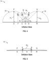
FIG. 4 is a height detection calculation schematic for an example pneumatic deicer boot of the present disclosure, the pneumatic deicer boot in the inflated position; -
FIG. 5 is a height detection calculation schematic for an example pneumatic deicer boot of the present disclosure, the pneumatic deicer boot in the deflated position; and -
FIG. 6 is a height detection correlation plot for an example pneumatic deicer boot of the present disclosure. - The example embodiments disclosed herein are illustrative of methods for detecting life or failure of pneumatic deicer boots for aircraft, and systems of the present disclosure and applications/techniques thereof. It should be understood, however, that the disclosed embodiments are merely examples of the present disclosure, which may be embodied in various forms. Therefore, details disclosed herein with reference to example methods and associated processes/techniques of fabrication/assembly and use are not to be interpreted as limiting, but merely as the basis for teaching one skilled in the art how to make and use the methods, systems and assemblies of the present disclosure.
- The present disclosure provides for methodologies for height measurement in pneumatic deicer boots for aircraft, and related models, systems and methods of use. More particularly, the present disclosure provides for methods, models, systems and applications to detect the life or failure of pneumatic deicer boots for aircraft.
- Current practice provides that pneumatic deicer boots can be made of two types of coated fabrics, a stretchable fabric and a non-stretchable fabric. The stretchable fabric stretches at regular intervals based on the pneumatic deicer design.
- In operation or service, two extreme cases/conditions can be observed in pneumatic deicer boots - an inflated condition and a deflated condition. The inflated condition is when the air is filled in the pneumatic deicer and the tubes are blown to the maximum extent. This is the case when ice gets broken from the surface of the deicer boot.
- The deflated condition is when vacuum is created in the tubes of the pneumatic deicer boot. The functional capability of the deicer boot depends on the height of inflation and deflation of the pneumatic deicer tubes. Knowing the height helps one to understand the air pressure in the deicer tubes and therefore the real time performance capability of the deicer boot.
- The present disclosure provides a method of measuring the height of inflation and deflation in a pneumatic deicer boot using image processing of a contrast colored deicer.
- An example method or process can be achieved by image processing using a camera which is focused on the aircraft wing or the like, and with the contrast colored pneumatic deicers on the aircraft. The stitched lines or areas of the pneumatic deicer tubes can be colored with a contrasting color strip or paint. The change in the thickness of this strip is with respect to the air pressure in the respective deicer tubes and is captured by the camera, and using a programming language the correlation between the strip thickness and the height of inflation and/or deflation is derived. The inflated and/or deflated tube height is measured based on pre-test data.
- For easy detection of the difference in the strip thickness, the color of the strip and the rest of the deicer surface should be of different colors. In image processing, the hardware based color models mainly used are: RGB (red, green, blue), CMYK (cyan, magenta, yellow, black), and HSI (hue, saturation, intensity). The RGB (red, green, blue) color system is used mainly in color monitors and video cameras. The contrast is defined as the difference between the highest and lowest intensity value of the image. The contrast between the stitched edge of the pneumatic deicer and the tubes can be done using glued strips or paint or another manufacturing process.
- The deicer tube height measurement works on the principle that when the deicer inflates the contrast colored strip on the edges of the tube or the stitched lines of the deicers changes its form or becomes thinner in the image captured by a camera. Similarly when the deicer deflates the contrast colored strip on the edges of the tube or the stitched lines of the deicers changes its form or becomes thicker in the image captured by a camera.
- This difference in the two images - the fully inflated image and the fully deflated image of the pneumatic deicer can be compared to measure the height of inflation and/or deflation that occurred using image processing techniques.
-
FIG. 1 is a top view of anexample aircraft 10 having apneumatic deicer boot 14 of the present disclosure. - The
pneumatic deicer boot 14 includes a contrast colored strip or area 16 (e.g., contrast strips/paint 16), with thepneumatic deicer boot 14 installed on the aircraft. - At least one stitched line or stitched
area 16 of at least onepneumatic deicer tube 18 ofdeicer boot 14 can be colored with a contrasting color strip orpaint 16. The change in the thickness of this strip/area 16 is with respect to the air pressure in thedeicer tubes 18 and is captured by acamera 12, and using a programming language the correlation between the strip/area 16 thickness and the height of inflation and/or deflation is derived. The inflated and/or deflatedtubes 18 height is measured based on pre-test data. - As noted and for easy detection of the difference in the
strip 16 thickness, the color of thestrip 16 and the rest of thedeicer 14 surface should be of different colors. When thedeicer 14 inflates, the contrast coloredstrip 16 on the edges of thetubes 18 or the stitched lines of thedeicer 14 changes its form or becomes thinner in the image captured by thecamera 12. Similarly, when thedeicer 14 deflates the contrast coloredstrip 16 on the edges of thetubes 18 or the stitched lines of thedeicer 14 changes its form or becomes thicker in the image captured by thecamera 12. As discussed further below, the difference in the two images (the fully inflated image and the fully deflated image of the pneumatic deicer 14) can be compared to measure the height of inflation and/or deflation that occurred using image processing techniques. - As noted, a camera 12 (e.g., high definition camera 12) can be focused on the
deicer 14 such that the variation in the form or width of thestrip 16 is detected. The captured images can be sent in real time to a processor or the like. Using a program, the variation in strip thickness or width is measured in the images. The thickness or width of thestrip 16 can be plotted against the inflation or deflation height of therespective tube 18 in a pre-tested graph which acts as the baseline values (SeeFIG. 6 ). Through correlation, the height of inflation or deflation of eachrespective tube 18 is measured. - The above mentioned technique can also be used to measure the height of the
deicer tube 18 during inflation by correlating thestrip 16 thickness or width with thetube 18 height. - Referring now to
FIGS. 4 and 5 , the distance or width W1 and W2 between the edges A, B of thestrip 16 during inflation and deflation conditions of thedeicer 14 can be measured. - As shown in
FIGS. 4 and 5 , the distance or height Hi, H2 for the centers P, Q of the twotubes 18 under consideration from surface S, R during inflation and deflation conditions of thedeicer 14 can be measured. The distance or width W1 and W2 between the edges A, B of thestrip 16 are noted at regular time intervals (in milliseconds), simultaneously the height Hi, H2 of inflation and deflation is measured with the help of linear variable differential transformer (LVDT), laser height sensor or any other accurate means. The distance or width W1 and W2 between the edges A, B of thestrip 16 and the height Hi, H2 of inflation and deflation of thedeicer tube 18 are correlated. This method can be repeated for better calibration. - The tube heights H1 and H2 and the distance or width W1 and W2 between the edges A, B of the
strip 16 at regular time intervals are plotted, and the height Hi, H2 at a given distance or width W1 and W2 between the edges A, B of thestrip 16 can be interpolated as shown inFIG. 6 . The distances or widths W1 and W2 between the edges A, B of the strip 16 (and distances C to O and D to O) change in value with the change in heights H1 and H2 during inflation and deflation states. - Failure is detected in the
pneumatic deicer boot 14 when there is no inflation or the inflation height is not adequate for thedeicer 14 to break the ice. InFIG. 6 , when there is a sudden drop in the height to zero or to a non-acceptable height for deicing, there will also be a sudden drop in the width of thestrip 16. With this indication, thedeicer boot 14 needs to be inspected, repaired, and/or replaced. Hence preventive maintenance of thepneumatic deicer 14 is possible with this method, system and assembly. - As such, the present disclosure provides for a new method of using image processing and contrast colored strips 16 in pneumatic deicer boots 14 for height measurement of the
pneumatic deicer tubes 18 for detecting life or failure of pneumatic deicer boots 14 foraircraft 10. - There are many benefits of the assemblies, systems and methods of the present disclosure, including, without limitation less space and less equipment required for life prediction of
pneumatic de-icers 14; can be used in testing activity; low capital required for full scale manufacturing; contactless inflation or deflation height measurement;camera 12 can be placed or positioned inside theaircraft 10 hence less prone to failure to external environmental conditions; preventive maintenance can be carried out; can be integrated with Internet of Things (IOT) systems; data collected can be used for data analytics; and/or provides opportunity to develop proprietary products. - While particular embodiments have been described, alternatives, modifications, variations, improvements, and substantial equivalents that are or may be presently unforeseen may arise to applicants or others skilled in the art. Accordingly, the appended claims as filed and as they may be amended are intended to embrace all such alternatives, modifications variations, improvements, and substantial equivalents.
- The ranges disclosed herein are inclusive of the endpoints, and the endpoints are independently combinable with each other (e.g., ranges of "up to 25 wt.%, or, more specifically, 5 wt.% to 20 wt.%", is inclusive of the endpoints and all intermediate values of the ranges of "5 wt.% to 25 wt.%," etc.). "Combinations" is inclusive of blends, mixtures, alloys, reaction products, and the like. The terms "first," "second," and the like, do not denote any order, quantity, or importance, but rather are used to distinguish one element from another. The terms "a" and "an" and "the" do not denote a limitation of quantity and are to be construed to cover both the singular and the plural, unless otherwise indicated herein or clearly contradicted by context. "Or" means "and/or" unless clearly stated otherwise. Reference throughout the specification to "some embodiments", "an embodiment", and so forth, means that a particular element described in connection with the embodiment is included in at least one embodiment described herein, and may or may not be present in other embodiments. In addition, it is to be understood that the described elements may be combined in any suitable manner in the various embodiments. A "combination thereof' is open and includes any combination comprising at least one of the listed components or properties optionally together with a like or equivalent component or property not listed.
- Unless defined otherwise, technical and scientific terms used herein have the same meaning as is commonly understood by one of skill in the art to which this application belongs. All cited patents, patent applications, and other references are incorporated herein by reference in their entirety. However, if a term in the present application contradicts or conflicts with a term in the incorporated reference, the term from the present application takes precedence over the conflicting term from the incorporated reference.
- Although the assemblies, systems and methods of the present disclosure have been described with reference to example embodiments thereof, the present disclosure is not limited to such example embodiments and/or implementations. Rather, the assemblies, systems and methods of the present disclosure are susceptible to many implementations and applications, as will be readily apparent to persons skilled in the art from the disclosure hereof. The present disclosure expressly encompasses such modifications, enhancements and/or variations of the disclosed embodiments. Since many changes could be made in the above construction and many widely different embodiments of this disclosure could be made without departing from the scope thereof, it is intended that all matter contained in the drawings and specification shall be interpreted as illustrative and not in a limiting sense. Additional modifications, changes, and substitutions are intended in the foregoing disclosure. Accordingly, it is appropriate that the appended claims be construed broadly and in a manner consistent with the scope of the disclosure.
Claims (15)
- A method for detecting life or failure of pneumatic deicer boots comprising:positioning a colored strip (16) on a pneumatic deicer boot (14), and installing the pneumatic deicer boot (14) on an aircraft;detecting variation of a width of the colored strip (16) via a camera (12) at pre-determined time intervals;plotting and correlating the width of the colored strip (16) against an inflation or deflation height of a tube of the pneumatic deicer boot (14) utilizing a pre-tested graph to determine the height of inflation or deflation of the tube at the pre-determined time intervals; andutilizing the height of inflation or deflation of the tube at the pre-determined time intervals to detect the life or failure of pneumatic deicer boot (14).
- The method of claim 1, wherein the camera (12) is positioned inside the aircraft.
- The method of any preceding claim, wherein the colored strip (16) includes a first color and the pneumatic deicer boot (14) includes a second color that is different than the first color.
- The method of any preceding claim, wherein the pneumatic deicer boot (14) is positioned on a wing of the aircraft.
- The method of any preceding claim, wherein the colored strip (16) is positioned on a stitched line or area of the tube, and/or wherein the colored strip (16) includes a glued strip (16) and/or comprises paint.
- The method of any preceding claim, wherein determining the height of inflation or deflation of the tube at the pre-determined time intervals comprises contactless inflation or deflation height measurement.
- The method of any preceding claim, wherein the camera (12) is a high definition camera (12), and/or wherein the colored strip (16) includes a plurality of colors.
- The method of any preceding claim, wherein the pneumatic deicer boot (14) includes a stretchable fabric and a non-stretchable fabric.
- A pneumatic deicer boot assembly comprising:a colored strip (16) positioned on a pneumatic deicer boot (14), the pneumatic deicer boot (14) installed on an aircraft;a camera (12) positioned on the aircraft, the camera (12) configured to detect variation of a width of the colored strip (16) at pre-determined time intervals;wherein variation of the width of the colored strip (16) at the pre-determined time intervals operates to determine a height of inflation or deflation of a tube of the pneumatic deicer boot (14) at the pre-determined time intervals to detect the life or failure of the pneumatic deicer boot (14).
- The assembly of claim 9, wherein the camera (12) is positioned inside the aircraft, or wherein the colored strip (16) is positioned on a stitched line or area of the tube.
- The assembly of claim 9 or 10, wherein the colored strip (16) includes a first color and the pneumatic deicer boot (14) includes a second color that is different than the first color.
- The assembly of any of claims 9 to 11, wherein the pneumatic deicer boot (14) is positioned on a wing of the aircraft.
- The assembly of any of claims 9 to 12, wherein the colored strip (16) includes a glued strip (16) and/or comprises paint and/or wherein the colored strip (16) includes a plurality of colors.
- The assembly of any of claims 9 to 13, wherein determining the height of inflation or deflation of the tube at the pre-determined time intervals comprises contactless inflation or deflation height measurement.
- The assembly of any of claims 9 to 14, wherein the camera (12) is a high definition camera (12), and/or wherein the pneumatic deicer boot (14) includes a stretchable fabric and a non-stretchable fabric.
Applications Claiming Priority (1)
| Application Number | Priority Date | Filing Date | Title |
|---|---|---|---|
| IN202311022607 | 2023-03-28 |
Publications (2)
| Publication Number | Publication Date |
|---|---|
| EP4438482A1 true EP4438482A1 (en) | 2024-10-02 |
| EP4438482B1 EP4438482B1 (en) | 2026-03-18 |
Family
ID=90468711
Family Applications (1)
| Application Number | Title | Priority Date | Filing Date |
|---|---|---|---|
| EP24165679.2A Active EP4438482B1 (en) | 2023-03-28 | 2024-03-22 | Methodology for height measurement in pneumatic deicer boots |
Country Status (2)
| Country | Link |
|---|---|
| US (1) | US12205262B2 (en) |
| EP (1) | EP4438482B1 (en) |
Citations (4)
| Publication number | Priority date | Publication date | Assignee | Title |
|---|---|---|---|---|
| US20160009400A1 (en) * | 2013-02-28 | 2016-01-14 | Gkn Aerospace Services Limited | Ice protection system |
| EP3415435A1 (en) * | 2017-06-16 | 2018-12-19 | Goodrich Corporation | Improved tube type pneumatic deicers |
| US20190016467A1 (en) * | 2017-07-14 | 2019-01-17 | Goodrich Corporation | Pneumatic deicer with sensors |
| EP3050804B1 (en) * | 2015-01-27 | 2019-03-06 | Goodrich Corporation | Health monitoring of a pneumatic deicer |
Family Cites Families (11)
| Publication number | Priority date | Publication date | Assignee | Title |
|---|---|---|---|---|
| US3720388A (en) * | 1970-03-06 | 1973-03-13 | Airborne Mfg Co | Method of and apparatus for controlling a deicer boot system |
| US4690353A (en) * | 1985-05-31 | 1987-09-01 | The United States Of America As Represented By The Administrator Of The National Aeronautics And Space Administration | Electro-expulsive separation system |
| FR2749562B1 (en) * | 1996-06-11 | 1998-08-07 | Eurocopter France | DEVICE FOR DEFROSTING AN EXTERNAL WALL OF A VEHICLE |
| GB2355243A (en) | 1999-10-13 | 2001-04-18 | Robert Cameron Bolam | Pneumatic de-icing system |
| US6736611B2 (en) | 2000-10-23 | 2004-05-18 | Goodrich Corporation | Aircraft fluid delivery device |
| CN101430195B (en) | 2008-12-19 | 2010-08-18 | 华北电力大学 | A Method of Calculating the Icing Thickness of Transmission Lines Using Video Image Processing Technology |
| WO2012000384A1 (en) | 2010-07-02 | 2012-01-05 | 中国商用飞机有限责任公司 | Detecting device for detecting icing by image and detecting method thereof |
| CN103196380B (en) | 2013-03-20 | 2016-06-08 | 北京国网富达科技发展有限责任公司 | Transmission line of electricity image collecting device and electric power line ice-covering thickness detection system |
| CN105514904A (en) | 2015-12-17 | 2016-04-20 | 无锡桑尼安科技有限公司 | Automatic deicing robot based on image detection |
| CN106649598A (en) | 2016-11-22 | 2017-05-10 | 云南电网有限责任公司电力科学研究院 | Detection method for icing thickness of power transmission line |
| CN106595551B (en) | 2016-12-13 | 2019-01-04 | 武汉大学 | Ice covering thickness detection method in powerline ice-covering image based on deep learning |
-
2023
- 2023-05-25 US US18/323,642 patent/US12205262B2/en active Active
-
2024
- 2024-03-22 EP EP24165679.2A patent/EP4438482B1/en active Active
Patent Citations (4)
| Publication number | Priority date | Publication date | Assignee | Title |
|---|---|---|---|---|
| US20160009400A1 (en) * | 2013-02-28 | 2016-01-14 | Gkn Aerospace Services Limited | Ice protection system |
| EP3050804B1 (en) * | 2015-01-27 | 2019-03-06 | Goodrich Corporation | Health monitoring of a pneumatic deicer |
| EP3415435A1 (en) * | 2017-06-16 | 2018-12-19 | Goodrich Corporation | Improved tube type pneumatic deicers |
| US20190016467A1 (en) * | 2017-07-14 | 2019-01-17 | Goodrich Corporation | Pneumatic deicer with sensors |
Also Published As
| Publication number | Publication date |
|---|---|
| US12205262B2 (en) | 2025-01-21 |
| US20240331123A1 (en) | 2024-10-03 |
| EP4438482B1 (en) | 2026-03-18 |
Similar Documents
| Publication | Publication Date | Title |
|---|---|---|
| EP3428067B1 (en) | Pneumatic deicer with sensors | |
| US8973428B2 (en) | Method and device for measuring a part in a turbine engine | |
| CN104931007B (en) | Method and device for automatically estimating parameters relating to the flight of an aircraft | |
| CN111351516A (en) | Sensor fault detection and identification using residual fault pattern recognition | |
| US6982655B2 (en) | Method and indicator for displaying information showing the airspeed tolerance margins for an aircraft | |
| US12205262B2 (en) | Methodology for height measurement in pneumatic deicer boots | |
| US20120074932A1 (en) | Nondestructive inspection of a structure in an aircraft | |
| US20240159162A1 (en) | System and method of using a tool assembly | |
| US11713692B2 (en) | Real time engine inlet barrier filter condition monitor | |
| EP3501990B1 (en) | Quantitative blockage analysis of a grid in icing conditions | |
| CN110087913A (en) | Method for determining the wear condition of aero tyre | |
| US20140338441A1 (en) | Apparatus and methods for the launch and recovery of craft from and to a host ship | |
| US20200189553A1 (en) | Method and system for monitoring the state of a brake of an aircraft | |
| CN109153443A (en) | The management method of aircraft tire and the managing device of aircraft tire | |
| EP3173890A1 (en) | Fault detection methods and systems | |
| US20090125168A1 (en) | Takeoff and landing performance indicator for fixed wing aircraft | |
| EP3584170B1 (en) | Cover for an exterior aircraft light, exterior aircraft light, and method of determining a wear state of a lens cover structure | |
| US10126175B2 (en) | Long wave infrared sensing for turbomachine | |
| EP3153815B1 (en) | Measuring device | |
| KR101808390B1 (en) | Method for machine fault diagnosis | |
| US8903680B2 (en) | Apparatus and method for evaluating layers in a multi-layer structure | |
| CN215375135U (en) | Auxiliary tool for hole inspection of turbine blade of aircraft engine | |
| CA3025555A1 (en) | System and method for automatically detecting leak noise in an aircraft | |
| US11835179B2 (en) | Systems and methods for monitoring evacuation assembly charge cylinders | |
| CN114206726A (en) | Monitoring method, computer program product, related monitoring system and aircraft |
Legal Events
| Date | Code | Title | Description |
|---|---|---|---|
| PUAI | Public reference made under article 153(3) epc to a published international application that has entered the european phase |
Free format text: ORIGINAL CODE: 0009012 |
|
| STAA | Information on the status of an ep patent application or granted ep patent |
Free format text: STATUS: THE APPLICATION HAS BEEN PUBLISHED |
|
| AK | Designated contracting states |
Kind code of ref document: A1 Designated state(s): AL AT BE BG CH CY CZ DE DK EE ES FI FR GB GR HR HU IE IS IT LI LT LU LV MC ME MK MT NL NO PL PT RO RS SE SI SK SM TR |
|
| STAA | Information on the status of an ep patent application or granted ep patent |
Free format text: STATUS: REQUEST FOR EXAMINATION WAS MADE |
|
| 17P | Request for examination filed |
Effective date: 20250402 |
|
| GRAP | Despatch of communication of intention to grant a patent |
Free format text: ORIGINAL CODE: EPIDOSNIGR1 |
|
| STAA | Information on the status of an ep patent application or granted ep patent |
Free format text: STATUS: GRANT OF PATENT IS INTENDED |
|
| INTG | Intention to grant announced |
Effective date: 20251006 |
|
| GRAS | Grant fee paid |
Free format text: ORIGINAL CODE: EPIDOSNIGR3 |
|
| GRAA | (expected) grant |
Free format text: ORIGINAL CODE: 0009210 |
|
| STAA | Information on the status of an ep patent application or granted ep patent |
Free format text: STATUS: THE PATENT HAS BEEN GRANTED |
|
| AK | Designated contracting states |
Kind code of ref document: B1 Designated state(s): AL AT BE BG CH CY CZ DE DK EE ES FI FR GB GR HR HU IE IS IT LI LT LU LV MC ME MK MT NL NO PL PT RO RS SE SI SK SM TR |
|
| REG | Reference to a national code |
Ref country code: CH Ref legal event code: F10 Free format text: ST27 STATUS EVENT CODE: U-0-0-F10-F00 (AS PROVIDED BY THE NATIONAL OFFICE) Effective date: 20260318 Ref country code: GB Ref legal event code: FG4D |
|
| REG | Reference to a national code |
Ref country code: DE Ref legal event code: R096 Ref document number: 602024003193 Country of ref document: DE |
|
| REG | Reference to a national code |
Ref country code: IE Ref legal event code: FG4D |
|
| PGFP | Annual fee paid to national office [announced via postgrant information from national office to epo] |
Ref country code: AT Payment date: 20260414 Year of fee payment: 3 |