EP4438477A1 - Passenger seat with self-stowing portable electronic device holder - Google Patents
Passenger seat with self-stowing portable electronic device holder Download PDFInfo
- Publication number
- EP4438477A1 EP4438477A1 EP24166475.4A EP24166475A EP4438477A1 EP 4438477 A1 EP4438477 A1 EP 4438477A1 EP 24166475 A EP24166475 A EP 24166475A EP 4438477 A1 EP4438477 A1 EP 4438477A1
- Authority
- EP
- European Patent Office
- Prior art keywords
- backstop
- shelf
- recess
- tray table
- seat back
- Prior art date
- Legal status (The legal status is an assumption and is not a legal conclusion. Google has not performed a legal analysis and makes no representation as to the accuracy of the status listed.)
- Pending
Links
Images



Classifications
-
- B—PERFORMING OPERATIONS; TRANSPORTING
- B64—AIRCRAFT; AVIATION; COSMONAUTICS
- B64D—EQUIPMENT FOR FITTING IN OR TO AIRCRAFT; FLIGHT SUITS; PARACHUTES; ARRANGEMENT OR MOUNTING OF POWER PLANTS OR PROPULSION TRANSMISSIONS IN AIRCRAFT
- B64D11/00—Passenger or crew accommodation; Flight-deck installations not otherwise provided for
- B64D11/0015—Arrangements for entertainment or communications, e.g. radio, television
- B64D11/00152—Seat back fixtures for removable monitors, e.g. tablet computers
-
- B—PERFORMING OPERATIONS; TRANSPORTING
- B64—AIRCRAFT; AVIATION; COSMONAUTICS
- B64D—EQUIPMENT FOR FITTING IN OR TO AIRCRAFT; FLIGHT SUITS; PARACHUTES; ARRANGEMENT OR MOUNTING OF POWER PLANTS OR PROPULSION TRANSMISSIONS IN AIRCRAFT
- B64D11/00—Passenger or crew accommodation; Flight-deck installations not otherwise provided for
- B64D11/06—Arrangements of seats, or adaptations or details specially adapted for aircraft seats
- B64D11/0602—Seat modules, i.e. seat systems including furniture separate from the seat itself
- B64D11/0605—Seat modules, i.e. seat systems including furniture separate from the seat itself including tables or desks
Definitions
- the present disclosure relates generally to passenger seat amenities, and more particularly, to a portable electronic device (PED) holder configured to deploy from a position behind a stowed tray table, wherein, in use, moving the tray table to a stowed position causes the PED holder to self-stow in a recess formed in the seat back.
- PED portable electronic device
- PEDs Portable electronic devices
- PEDs Portable electronic devices
- economy seating classes including seat back tray tables
- PED holders may be integrated into the seat back or built into the tray table.
- Current tray able solutions consume tabletop space, whereas current seat back solutions do not maintain a desirable viewing angle throughout the range of motion of the seat back.
- neither current solution type coordinates PED holder stowing with the stowing motion of the tray table.
- the present disclosure provides a passenger seat including a seat back, a shroud positioned on a back of the seat back, a recess formed in the shroud, and a tray table configured to stow against the shroud, deploy away from the shroud, and cover the recess when the tray table is fully stowed.
- the passenger seat further includes a portable electronic device holder (PED) including a backstop pivotally attached along a top edge thereof to the seat back and configured to rotate between a stowed position in the recess and a deployed position outside of the recess, and a shelf pivotally attached along one edge thereof to a bottom edge of the backstop.
- PED portable electronic device holder
- an angle formed between the backstop and a vertical axis is no greater than about negative 45 degrees.
- the shelf is oriented substantially horizontal.
- the backstop is pivotally attached to the seat back by at least one friction hinge
- the shelf is pivotally attached to the backstop by at least one friction hinge
- a portion of the at least one friction hinge pivotally attaching the backstop to the seat back is integrally formed with the backstop
- a portion of the at least one friction hinge pivotally attaching the shelf to the backstop is integrally formed with the shelf
- a portion of the at least one friction hinge pivotally attaching the shelf to the backstop is integrally formed with the backstop.
- the at least one friction hinge pivotally attaching the backstop to the seat back defines an upper pivot point located within the recess or above the recess and concealed from view behind a portion of the shroud.
- the shelf when the tray table and the PED are fully deployed, the shelf is spaced apart above the tray table.
- the shelf includes a raised lip formed along a free edge of the shelf, a handle formed along a middle portion of the raised lip, and a plurality of transverse ridges formed along a top surface of the shelf.
- the PED holder is not available for use when the tray table is fully stowed.
- the passenger seat further includes a tray table latch positioned above the recess and a video monitor positioned above the tray table latch.
- a length of the backstop substantially corresponds to a height of the recess, and a length of the shelf is less than a length of the backstop.
- the present disclosure provides a PED holder configured to be installed in a recess formed in seat back of a passenger seat, the recess located behind a stowed tray table associated with the seat back.
- the PED holder includes a backstop configured to be pivotally attached along a top edge thereof to the seat back, the backstop configured to rotate between a stowed position in the recess and a deployed position outside of the recess, and a shelf pivotally attached along one edge thereof to a bottom edge of the backstop.
- an angle formed between the backstop and a vertical axis is no greater than about negative 45 degrees.
- the shelf is fully deployed, the shelf is oriented substantially horizontal.
- stowing movement of the tray table is configured to cause the shelf to rotate against the backstop and the backstop to rotate into the recess.
- the present disclosure provides an assembly configured to be installed on a back of a passenger seat, the passenger seat including a tray table configured to cover the assembly when the tray table is in a stowed condition.
- the assembly includes a shroud configured to be affixed to the passenger seat, the shroud defining a recess.
- the assembly further includes a portable electronic device holder (PED) including a backstop pivotally attached along a top edge thereof to the shroud, for example through a bracket, the backstop configured to rotate between a stowed position in the recess and a deployed position outside of the recess, and a shelf pivotally attached along one edge thereof to a bottom edge of the backstop.
- PED portable electronic device holder
- an angle formed between the backstop and a vertical axis is no greater than about negative 45 degrees.
- the shelf is oriented substantially horizontal.
- stowing the tray table is configured to cause the shelf to rotate against the backstop and the backstop to rotate into the recess.
- inventive concepts disclosed herein are not limited in their application to the details of construction and the arrangement of the components or steps or methodologies set forth in the following description or illustrated in the drawings.
- inventive concepts disclosed herein may be practiced without these specific details.
- well-known features may not be described in detail to avoid unnecessarily complicating the present disclosure.
- inventive concepts disclosed herein are capable of other embodiments or of being practiced or carried out in various ways. Also, it is to be understood that the phraseology and terminology employed herein is for the purpose of description and should not be regarded as limiting.
- a letter following a reference numeral is intended to reference an embodiment of the feature or element that may be similar, but not necessarily identical, to a previously described element or feature bearing the same reference numeral (e.g., 1, 1a, 1b).
- Such shorthand notations are used for purposes of convenience only, and should not be construed to limit the inventive concepts disclosed herein in any way unless expressly stated to the contrary.
- "or" refers to an inclusive or and not to an exclusive or.
- a condition A or B is satisfied by any one of the following: A is true (or present) and B is false (or not present), A is false (or not present) and B is true (or present), and both A and B are true (or present).
- use of the "a” or “an” are employed to describe elements and components of embodiments of the present inventive concepts. This is done merely for convenience and to give a general sense of the inventive concepts, and "a” and “an” are intended to include one or at least one and the singular also includes the plural unless it is obvious that it is meant otherwise.
- any reference to “one embodiment” or “some embodiments” means that a particular element, feature, structure, or characteristic described in connection with the embodiment is included in at least one embodiment of the inventive concepts disclosed herein.
- the appearances of the phrase “in some embodiments” in various places in the specification are not necessarily all referring to the same embodiment, and embodiments of the inventive concepts disclosed may include one or more of the features expressly described or inherently present herein, or any combination or sub-combination of two or more such features, along with any other features which may not necessarily be expressly described or inherently present in the present disclosure.
- the present disclosure provides provisions for accommodating personal electronic devices in an aircraft.
- the present disclosure provides a passenger seat equipped with a tray table configured to stow against a seat back, and a PED holder positioned in the seat back behind the tray table when in the tray table is stowed.
- the tray table is deployed to reveal the PED holder, and the PED holder is separately deployed as needed.
- the stowing motion of the tray table causes the tray table to engage the fully deployed PED holder, thereby causing the PED holder to rotate into a closed or folded position with a recess formed in the seat back. Friction hinges maintain a positional relationship of the PED holder relative to the seat back and between components of the PED holder itself.
- a PED holder assembly is configured to be installed on a seat back.
- FIG. 1 illustrates a passenger seat 100 according to an embodiment of the present disclosure.
- the passenger seat 100 includes a seat back 102 that may be configured to rotate between an upright position for taxi, takeoff, and landing (TTOL) and a reclined position during flight.
- a tray table 104 affixed to or associated with the passenger seat 100 is configured to rotate between a stowed position against the back of the seat back 102 and a deployed position apart from the seat back 102 in which the tray table 104 is oriented substantially horizontal.
- the tray table 104 may include mechanisms for one or more of tabletop expansion, and forward, aft, and lateral adjustment.
- the tray table 104 is supported by a frame 106 affixed to a pair of support arms 108.
- the support arms 108 may be affixed to the seat frame such that seat back recline does not affect the tray table position.
- the passenger seat 100 further includes a latch 110 configured to engage the tray table 104 to maintain the stowed position of the tray table, and a video monitor 112 positioned above the latch 110.
- the back of the passenger seat 100 may be substantially covered by a shroud 114 provided in one or more sections.
- a first section 116 may correspond to the upper portion of the seat back 102 and accommodate the latch 110 and the video monitor 112
- a second section 118 may correspond to the middle portion of the seat back 102 and accommodate the PED holder as discussed below.
- the shroud 114 may include additional sections, for instance a lower section forming a literature pocket.
- the shroud second section 118 accommodates the PED holder 120.
- the tray table 104 is dimensioned and positioned such that, when the tray table 104 is fully stowed flush against the seat back 102, the tray table 104 covers the PED holder 120. As such, the PED holder 120 is not available for use when the tray table 104 is stowed during TTOL and otherwise.
- the tray table 104 is rotated to the deployed position as shown in FIG. 1 , the PED holder 120 is visible to the passenger and available for use. Deploying the tray table 104 does not cause the PED holder 120 to deploy.
- the shroud second section 118 forms a recess 122 dimensioned to accommodate the PED holder 120 in a stowed condition.
- the recess 122 includes a top, a bottom, lateral sides, and a back.
- the front of the recess 122 is open to receive the PED holder 120.
- the PED holder 120 may be positioned flush with the surrounding portions of the shroud second section 118.
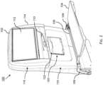
- FIG. 2 illustrates the PED holder 120 in a deployed condition, for instance a fully deployed condition.
- the PED holder 120 generally includes a backstop 124 pivotally attached along a top edge thereof to the seat back 102.
- the PED holder 120 may attached to the shroud second section 118, such as by a bracket.
- the PED holder 120 further includes a shelf 126 pivotally attached along one edge thereof to a bottom edge of the backstop 124.
- the backstop 124 is pivotally attached to the seat back 102 such that a bottom edge of the backstop is configured to rotate between a stowed position within the recess 122 and a deployed position outside of the recess 122.
- the shelf 126 is pivotally attached to the backstop 124 such that the shelf 126 is configured to rotate between a stowed position against the backstop 124 and a deployed position apart from the backstop 124 in which the shelf 26 is oriented substantially horizontal.
- a mechanical stop associated with the hinged connections of the backstop 124 and shelf 126 operates to limit rotation of the respective components. When fully deployed, the shelf 126 is positioned above and spaced apart from the underlying tray table 104.
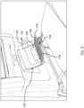
- FIG. 3 illustrates the PED holder 120 in use holding various sized PEDs, for instance smartphones 128 and tablets 130 of various sizes.
- the shelf 126 supports the PED from below and the PED leans against the backstop 124.
- the shelf 126 includes a raised lip 132 formed along a free edge thereof (i.e., the forward edge) for preventing the supported bottom of the device from falling off the shelf 126, a handle 134 formed along a middle portion of the raised lip 132 for deploying the PED holder 120 and manipulating the shelf 126, and at least one transverse ridge 136 formed on the top surface of the shelf 126 for maintain stable angular positions of the supported device.
- a particular transverse ridge 136 can be used to constrain the bottom of the PED, and the handle 134 can be used to grip the shelf 126.
- FIG. 4 illustrates an assembly including a shroud 118 and a PED holder 120 affixed to the shroud 118.
- the shroud occupies a middle portion of a seat back and defines a recess for accommodating the PED holder 120.
- the backstop 124 is pivotally attached to the seat back 102 or to the shroud 118 by at least one friction hinge 138, and the shelf 126 is pivotally attached to the backstop 124 by at least one friction hinge 140.
- a portion of the at least one friction hinge 138 pivotally attaching the backstop 124 to the seat back 102 may be integrally formed with the backstop 124.
- a portion of the at least one friction hinge 140 pivotally attaching the shelf 126 to the backstop 124 may be integrally formed with the shelf 126, and another portion of the at least one friction hinge 140 pivotally attaching the shelf 126 to the backstop 124 may be integrally formed with the backstop 124.
- the at least one friction hinge 138 pivotally attaching the backstop 124 to the shroud 118 defines an upper pivot point 142 located within the recess 122 or above the recess 122 and concealed from view behind a portion of the shroud 118.
- FIG. 5 illustrates the PED holder in a deployed condition in which the backstop 124 is rotated away from the recess 122 and the shelf 126 is rotated downward toward horizontal.
- the friction hinges 138, 140 allow the backstop 124 to be positioned at a predetermined angle relative to the seat back 102 and the shelf 126 to be positioned at a predetermined angle, within their angular range, relative to the backstop 124.
- the friction hinges 138, 140 operate to resist unintentional movements and require a predetermined amount of force to overcome the hinge resistance.
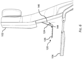
- FIG. 6 illustrates the relative positions of the backstop 124 and the shelf 126 in their fully deployed positions.
- an angle 144 formed between the backstop 124 and a vertical axis 146 is no greater than about negative 45 degrees, and the shelf 126 is oriented substantially horizontal.
- the backstop 124 is positioned such that the backstop 124 does not prevent the tray table 104 from being rotated toward its stowed condition, and instead engagement of the rotating tray table 104 with the deployed backstop 124 and/or shelf 126 causes the shelf 126 to rotate toward the backstop 126 and the pair to rotate toward the recess with continued stowing motion of the tray table 104.
- the PED holder 120 is self-closing in that the closing motion can be coordinated with the stowing motion of the tray table 104.
- the PED holder 120 can also be closed manually while the tray table 104 remains deployed.
Landscapes
- Engineering & Computer Science (AREA)
- Aviation & Aerospace Engineering (AREA)
- Chair Legs, Seat Parts, And Backrests (AREA)
- Passenger Equipment (AREA)
Abstract
Description
- The present disclosure relates generally to passenger seat amenities, and more particularly, to a portable electronic device (PED) holder configured to deploy from a position behind a stowed tray table, wherein, in use, moving the tray table to a stowed position causes the PED holder to self-stow in a recess formed in the seat back.
- Portable electronic devices (PEDs) such as tablets and smartphones are commonly used on aircraft. In economy seating classes including seat back tray tables, PED holders may be integrated into the seat back or built into the tray table. Current tray able solutions consume tabletop space, whereas current seat back solutions do not maintain a desirable viewing angle throughout the range of motion of the seat back. In addition, neither current solution type coordinates PED holder stowing with the stowing motion of the tray table.
- Therefore, it would be desirable to provide a PED holder solution for a passenger seat that is intuitive to operate, accommodates seat back recline, and does not interfere with use of the tray table.
- In a first aspect, the present disclosure provides a passenger seat including a seat back, a shroud positioned on a back of the seat back, a recess formed in the shroud, and a tray table configured to stow against the shroud, deploy away from the shroud, and cover the recess when the tray table is fully stowed. The passenger seat further includes a portable electronic device holder (PED) including a backstop pivotally attached along a top edge thereof to the seat back and configured to rotate between a stowed position in the recess and a deployed position outside of the recess, and a shelf pivotally attached along one edge thereof to a bottom edge of the backstop. When the backstop is fully deployed, an angle formed between the backstop and a vertical axis is no greater than about negative 45 degrees. When the shelf is fully deployed, the shelf is oriented substantially horizontal. When the tray table, the backstop, and the shelf are each fully deployed, stowing the tray table causes the shelf to rotate against the backstop and the backstop to rotate into the recess.
- In some embodiments, the backstop is pivotally attached to the seat back by at least one friction hinge, and the shelf is pivotally attached to the backstop by at least one friction hinge.
- In some embodiments, a portion of the at least one friction hinge pivotally attaching the backstop to the seat back is integrally formed with the backstop, a portion of the at least one friction hinge pivotally attaching the shelf to the backstop is integrally formed with the shelf, and a portion of the at least one friction hinge pivotally attaching the shelf to the backstop is integrally formed with the backstop.
- In some embodiments, the at least one friction hinge pivotally attaching the backstop to the seat back defines an upper pivot point located within the recess or above the recess and concealed from view behind a portion of the shroud.
- In some embodiments, when the tray table and the PED are fully deployed, the shelf is spaced apart above the tray table.
- In some embodiments, the shelf includes a raised lip formed along a free edge of the shelf, a handle formed along a middle portion of the raised lip, and a plurality of transverse ridges formed along a top surface of the shelf.
- In some embodiments, the PED holder is not available for use when the tray table is fully stowed.
- In some embodiments, the passenger seat further includes a tray table latch positioned above the recess and a video monitor positioned above the tray table latch.
- In some embodiments, a length of the backstop substantially corresponds to a height of the recess, and a length of the shelf is less than a length of the backstop.
- In another aspect, the present disclosure provides a PED holder configured to be installed in a recess formed in seat back of a passenger seat, the recess located behind a stowed tray table associated with the seat back. The PED holder includes a backstop configured to be pivotally attached along a top edge thereof to the seat back, the backstop configured to rotate between a stowed position in the recess and a deployed position outside of the recess, and a shelf pivotally attached along one edge thereof to a bottom edge of the backstop. When the backstop is fully deployed, an angle formed between the backstop and a vertical axis is no greater than about negative 45 degrees. When the shelf is fully deployed, the shelf is oriented substantially horizontal. When the tray table, the backstop, and the shelf are each fully deployed, stowing movement of the tray table is configured to cause the shelf to rotate against the backstop and the backstop to rotate into the recess.
- In a further aspect, the present disclosure provides an assembly configured to be installed on a back of a passenger seat, the passenger seat including a tray table configured to cover the assembly when the tray table is in a stowed condition. The assembly includes a shroud configured to be affixed to the passenger seat, the shroud defining a recess. The assembly further includes a portable electronic device holder (PED) including a backstop pivotally attached along a top edge thereof to the shroud, for example through a bracket, the backstop configured to rotate between a stowed position in the recess and a deployed position outside of the recess, and a shelf pivotally attached along one edge thereof to a bottom edge of the backstop. When the backstop is fully deployed, an angle formed between the backstop and a vertical axis is no greater than about negative 45 degrees. When the shelf is fully deployed, the shelf is oriented substantially horizontal. When the tray table, the backstop, and the shelf are each fully deployed, stowing the tray table is configured to cause the shelf to rotate against the backstop and the backstop to rotate into the recess.
- The detailed description is described with reference to the accompanying figures. The use of the same reference numbers in different instances in the description and the figures may indicate similar or identical items. Various embodiments or examples ("examples") of the disclosure are disclosed in the following detailed description and the accompanying drawings. The drawings are not necessarily to scale. In general, operations of disclosed processes may be performed in an arbitrary order, unless otherwise provided in the claims. In the drawings:
-
FIG. 1 is an isometric view of a passenger seat including a PED holder according to an embodiment of the present disclosure, showing the PED holder in a stowed condition; -
FIG. 2 is an isometric view of the passenger seat ofFIG. 1 , showing the PED holder in a deployed condition; -
FIG. 3 is a detailed view of the passenger seat ofFIG. 1 , showing the PED holder in use holding different PEDs; -
FIG. 4 is a perspective view of a PED holder assembly, according to an embodiment of the present disclosure, showing the PED holder in a stowed condition; -
FIG. 5 is a perspective view of a passenger seat showing the assembly ofFIG. 4 affixed to the passenger seat; and -
FIG. 6 is a side view of the passenger seat ofFIG. 1 , showing the tray table deployed, the PED holder deployed, and the respective angles of the backstop and the shelf when deployed. - Before explaining embodiments of the inventive concepts disclosed herein in detail, it is to be understood that the inventive concepts disclosed herein are not limited in their application to the details of construction and the arrangement of the components or steps or methodologies set forth in the following description or illustrated in the drawings. In the following detailed description of embodiments of the present disclosure, numerous specific details are set forth in order to provide a more thorough understanding of the inventive concepts. However, it will be apparent to one of ordinary skill in the art having the benefit of the present disclosure that the inventive concepts disclosed herein may be practiced without these specific details. In other instances, well-known features may not be described in detail to avoid unnecessarily complicating the present disclosure. The inventive concepts disclosed herein are capable of other embodiments or of being practiced or carried out in various ways. Also, it is to be understood that the phraseology and terminology employed herein is for the purpose of description and should not be regarded as limiting.
- As used herein, where applicable, a letter following a reference numeral is intended to reference an embodiment of the feature or element that may be similar, but not necessarily identical, to a previously described element or feature bearing the same reference numeral (e.g., 1, 1a, 1b). Such shorthand notations are used for purposes of convenience only, and should not be construed to limit the inventive concepts disclosed herein in any way unless expressly stated to the contrary. Further, unless expressly stated to the contrary, "or" refers to an inclusive or and not to an exclusive or. For example, a condition A or B is satisfied by any one of the following: A is true (or present) and B is false (or not present), A is false (or not present) and B is true (or present), and both A and B are true (or present). In addition, use of the "a" or "an" are employed to describe elements and components of embodiments of the present inventive concepts. This is done merely for convenience and to give a general sense of the inventive concepts, and "a" and "an" are intended to include one or at least one and the singular also includes the plural unless it is obvious that it is meant otherwise.
- Finally, as used herein any reference to "one embodiment" or "some embodiments" means that a particular element, feature, structure, or characteristic described in connection with the embodiment is included in at least one embodiment of the inventive concepts disclosed herein. The appearances of the phrase "in some embodiments" in various places in the specification are not necessarily all referring to the same embodiment, and embodiments of the inventive concepts disclosed may include one or more of the features expressly described or inherently present herein, or any combination or sub-combination of two or more such features, along with any other features which may not necessarily be expressly described or inherently present in the present disclosure.
- Broadly, the present disclosure provides provisions for accommodating personal electronic devices in an aircraft. In a particular implementation, the present disclosure provides a passenger seat equipped with a tray table configured to stow against a seat back, and a PED holder positioned in the seat back behind the tray table when in the tray table is stowed. In use, the tray table is deployed to reveal the PED holder, and the PED holder is separately deployed as needed. In use, the stowing motion of the tray table causes the tray table to engage the fully deployed PED holder, thereby causing the PED holder to rotate into a closed or folded position with a recess formed in the seat back. Friction hinges maintain a positional relationship of the PED holder relative to the seat back and between components of the PED holder itself. In a further aspect, a PED holder assembly is configured to be installed on a seat back.
-
FIG. 1 illustrates apassenger seat 100 according to an embodiment of the present disclosure. Thepassenger seat 100 includes a seat back 102 that may be configured to rotate between an upright position for taxi, takeoff, and landing (TTOL) and a reclined position during flight. A tray table 104 affixed to or associated with thepassenger seat 100 is configured to rotate between a stowed position against the back of the seat back 102 and a deployed position apart from the seat back 102 in which the tray table 104 is oriented substantially horizontal. The tray table 104 may include mechanisms for one or more of tabletop expansion, and forward, aft, and lateral adjustment. In a non-limiting example, the tray table 104 is supported by aframe 106 affixed to a pair ofsupport arms 108. Thesupport arms 108 may be affixed to the seat frame such that seat back recline does not affect the tray table position. - The
passenger seat 100 further includes alatch 110 configured to engage the tray table 104 to maintain the stowed position of the tray table, and avideo monitor 112 positioned above thelatch 110. The back of thepassenger seat 100 may be substantially covered by ashroud 114 provided in one or more sections. For example, afirst section 116 may correspond to the upper portion of the seat back 102 and accommodate thelatch 110 and thevideo monitor 112, while asecond section 118 may correspond to the middle portion of the seat back 102 and accommodate the PED holder as discussed below. Theshroud 114 may include additional sections, for instance a lower section forming a literature pocket. - In a middle portion of the seat back 102, the shroud
second section 118 accommodates thePED holder 120. The tray table 104 is dimensioned and positioned such that, when the tray table 104 is fully stowed flush against the seat back 102, the tray table 104 covers thePED holder 120. As such, thePED holder 120 is not available for use when the tray table 104 is stowed during TTOL and otherwise. When the tray table 104 is rotated to the deployed position as shown inFIG. 1 , thePED holder 120 is visible to the passenger and available for use. Deploying the tray table 104 does not cause thePED holder 120 to deploy. - The shroud
second section 118 forms arecess 122 dimensioned to accommodate thePED holder 120 in a stowed condition. Therecess 122 includes a top, a bottom, lateral sides, and a back. The front of therecess 122 is open to receive thePED holder 120. When fully stowed, thePED holder 120 may be positioned flush with the surrounding portions of the shroudsecond section 118. -
FIG. 2 illustrates thePED holder 120 in a deployed condition, for instance a fully deployed condition. ThePED holder 120 generally includes abackstop 124 pivotally attached along a top edge thereof to the seat back 102. In some embodiments, thePED holder 120 may attached to the shroudsecond section 118, such as by a bracket. ThePED holder 120 further includes ashelf 126 pivotally attached along one edge thereof to a bottom edge of thebackstop 124. Thebackstop 124 is pivotally attached to the seat back 102 such that a bottom edge of the backstop is configured to rotate between a stowed position within therecess 122 and a deployed position outside of therecess 122. Theshelf 126 is pivotally attached to thebackstop 124 such that theshelf 126 is configured to rotate between a stowed position against thebackstop 124 and a deployed position apart from thebackstop 124 in which the shelf 26 is oriented substantially horizontal. In some embodiments, a mechanical stop associated with the hinged connections of thebackstop 124 andshelf 126 operates to limit rotation of the respective components. When fully deployed, theshelf 126 is positioned above and spaced apart from the underlying tray table 104. -
FIG. 3 illustrates thePED holder 120 in use holding various sized PEDs, forinstance smartphones 128 andtablets 130 of various sizes. In use, theshelf 126 supports the PED from below and the PED leans against thebackstop 124. In some embodiments, theshelf 126 includes a raisedlip 132 formed along a free edge thereof (i.e., the forward edge) for preventing the supported bottom of the device from falling off theshelf 126, ahandle 134 formed along a middle portion of the raisedlip 132 for deploying thePED holder 120 and manipulating theshelf 126, and at least onetransverse ridge 136 formed on the top surface of theshelf 126 for maintain stable angular positions of the supported device. In use, a particulartransverse ridge 136 can be used to constrain the bottom of the PED, and thehandle 134 can be used to grip theshelf 126. -
FIG. 4 illustrates an assembly including ashroud 118 and aPED holder 120 affixed to theshroud 118. In some embodiments, the shroud occupies a middle portion of a seat back and defines a recess for accommodating thePED holder 120. In some embodiments, thebackstop 124 is pivotally attached to the seat back 102 or to theshroud 118 by at least onefriction hinge 138, and theshelf 126 is pivotally attached to thebackstop 124 by at least onefriction hinge 140. In some embodiments, a portion of the at least onefriction hinge 138 pivotally attaching thebackstop 124 to the seat back 102 may be integrally formed with thebackstop 124. In some embodiments, a portion of the at least onefriction hinge 140 pivotally attaching theshelf 126 to thebackstop 124 may be integrally formed with theshelf 126, and another portion of the at least onefriction hinge 140 pivotally attaching theshelf 126 to thebackstop 124 may be integrally formed with thebackstop 124. The at least onefriction hinge 138 pivotally attaching thebackstop 124 to theshroud 118 defines anupper pivot point 142 located within therecess 122 or above therecess 122 and concealed from view behind a portion of theshroud 118. -
FIG. 5 illustrates the PED holder in a deployed condition in which thebackstop 124 is rotated away from therecess 122 and theshelf 126 is rotated downward toward horizontal. In use, the friction hinges 138, 140 allow thebackstop 124 to be positioned at a predetermined angle relative to the seat back 102 and theshelf 126 to be positioned at a predetermined angle, within their angular range, relative to thebackstop 124. The friction hinges 138, 140 operate to resist unintentional movements and require a predetermined amount of force to overcome the hinge resistance. -
FIG. 6 illustrates the relative positions of thebackstop 124 and theshelf 126 in their fully deployed positions. When fully deployed, anangle 144 formed between thebackstop 124 and avertical axis 146 is no greater than about negative 45 degrees, and theshelf 126 is oriented substantially horizontal. By limiting the angle to such a maximum negative angle, thebackstop 124 is positioned such that thebackstop 124 does not prevent the tray table 104 from being rotated toward its stowed condition, and instead engagement of the rotating tray table 104 with the deployedbackstop 124 and/orshelf 126 causes theshelf 126 to rotate toward thebackstop 126 and the pair to rotate toward the recess with continued stowing motion of the tray table 104. Thus, thePED holder 120 is self-closing in that the closing motion can be coordinated with the stowing motion of the tray table 104. ThePED holder 120 can also be closed manually while the tray table 104 remains deployed.
Claims (15)
- A passenger seat (100), comprising:a seat back (102);a shroud (114) positioned on a back of the seat back;a recess (122) formed in the shroud;a tray table (104) configured to stow against the shroud, deploy away from the shroud, and cover the recess when the tray table is fully stowed; anda portable electronic device (PED) holder (120), comprising:a backstop (124) pivotally attached along a top edge thereof to the seat back, the backstop configured to rotate between a stowed position in the recess and a deployed position outside of the recess; anda shelf (126) pivotally attached along one edge thereof to a bottom edge of the backstop;wherein, when the backstop (124) is fully deployed, an angle formed between the backstop and a vertical axis is no greater than about negative 45 degrees; andwherein, when the shelf (126) is fully deployed, the shelf is oriented substantially horizontal;wherein, when the tray table (104), the backstop (124), and the shelf (126) are each fully deployed, stowing the tray table causes the shelf to rotate against the backstop and the backstop to rotate into the recess.
- The passenger seat (100) according to claim 1, wherein:the backstop (124) is pivotally attached to the seat back by at least one friction hinge (138); andthe shelf (126) is pivotally attached to the backstop by at least one friction hinge (140), and preferably wherein:a portion of the at least one friction hinge (138) pivotally attaching the backstop (124) to the seat back (102) is integrally formed with the backstop;a portion of the at least one friction hinge (140) pivotally attaching the shelf (126) to the backstop is integrally formed with the shelf; anda portion of the at least one friction hinge (140) pivotally attaching the shelf to the backstop is integrally formed with the backstop.
- The passenger seat (100) according to any preceding claim, wherein the at least one friction hinge (138) pivotally attaching the backstop (124) to the seat back (102) defines an upper pivot point located within the recess (122), or above the recess concealed from view behind a portion of the shroud (114).
- The passenger seat (100) according to any preceding claim, wherein, when the tray table (104) and the PED (120) are fully deployed, the shelf (126) is spaced apart above the tray table.
- The passenger seat (100) according to any preceding claim, wherein the shelf (126) comprises:a raised lip (132) formed along a free edge of the shelf;a handle (134) formed along a middle portion of the raised lip; anda plurality of transverse ridges (136) formed along a top surface of the shelf.
- The passenger seat (100) according to any preceding claim, wherein the PED holder (120) is not available for use when the tray table is fully stowed.
- The passenger seat (100) according to any preceding claim, further comprising a tray table latch (110) positioned above the recess and a video monitor (112) positioned above the tray table latch.
- The passenger seat (100) according to any preceding claim, wherein:a length of the backstop (124) substantially corresponds to a height of the recess (122); anda length of the shelf (126) is less than a length of the backstop.
- A portable electronic device (PED) holder (120) configured to be installed in a recess (122) formed in a seat back (102), the recess located behind a tray table (104) of the seat back when the tray table is in a stowed position, the PED holder (120) comprising:a backstop (124) configured to be pivotally attached along a top edge thereof to the seat back, the backstop configured to rotate between a stowed position in the recess and a deployed position outside of the recess; anda shelf (126) pivotally attached along one edge thereof to a bottom edge of the backstop;wherein, when the backstop (124) is fully deployed, an angle formed between the backstop and a vertical axis is no greater than about negative 45 degrees; andwherein, when the shelf (126) is fully deployed, the shelf is oriented substantially horizontal;wherein, when the tray table (104), the backstop (124), and the shelf (126) are each fully deployed, stowing movement of the tray table is configured to cause the shelf to rotate against the backstop and the backstop to rotate into the recess.
- The PED holder (120) according to claim 9, wherein:the backstop (124) includes at least one friction hinge (138) along a top edge thereof configured to attach to the seat back; andthe shelf (126) is pivotally attached to the backstop by at least one friction hinge (140), and preferably wherein:a portion of the at least one friction hinge (138) for pivotally attaching the backstop (124) to the seat back (102) is integrally formed with the backstop;a portion of the at least one friction hinge (140) pivotally attaching the shelf (126) to the backstop is integrally formed with the shelf; anda portion of the at least one friction hinge (140) pivotally attaching the shelf to the backstop is integrally formed with the backstop.
- The PED holder (120) according to claim 9 or 10, wherein the at least one friction hinge (138) for pivotally attaching the backstop (124) to the seat back (102) defines an upper pivot point to be located within the recess or above the recess (122) and concealed from view behind a portion of the seat back.
- The PED holder (120) according to any of claims 9-11, wherein, when the PED holder is fully deployed, the shelf (126) is configured to be spaced apart above the tray table (104); and/or
wherein the shelf (126) comprises:a raised lip (132) formed along a free edge of the shelf;a handle (134) formed along a middle portion of the raised lip; anda plurality of transverse ridges (136) formed along a top surface of the shelf; and/orwherein the PED holder is not available for use when the tray table (104) is fully stowed. - An assembly configured to be installed on a back of a passenger seat (100), the passenger seat including a tray table (104) configured to cover the assembly when the tray table is in a stowed position, the assembly comprising:a shroud (114) configured to be affixed to the passenger seat, the shroud defining a recess (122); anda portable electronic device holder (PED) (120), comprising:a backstop (124) pivotally attached along a top edge thereof to the shroud, the backstop configured to rotate between a stowed position in the recess and a deployed position outside of the recess; anda shelf (126) pivotally attached along one edge thereof to a bottom edge of the backstop;wherein, when the backstop (124) is fully deployed, an angle formed between the backstop and a vertical axis is no greater than about negative 45 degrees; andwherein, when the shelf (126) is fully deployed, the shelf is oriented substantially horizontal;wherein, when the tray table (104), the backstop (124), and the shelf (126) are each fully deployed, stowing the tray table is configured to cause the shelf to rotate against the backstop and the backstop to rotate into the recess.
- The assembly according to claim 13, wherein:the backstop (124) is pivotally attached to the shroud (114) by at least one friction hinge (138); andthe shelf (126) is pivotally attached to the backstop (124) by at least one friction hinge (140), and preferably wherein:a portion of the at least one friction hinge (138) pivotally attaching the backstop (124) to the shroud (114) is integrally formed with the backstop;a portion of the at least one friction hinge (140) pivotally attaching the shelf (126) to the backstop is integrally formed with the shelf; anda portion of the at least one friction hinge (140) pivotally attaching the shelf to the backstop is integrally formed with the backstop.
- The assembly according to claim 13 or 14, wherein the shelf comprises:a raised lip (132) formed along a free edge of the shelf;a handle (134) formed along a middle portion of the raised lip; anda plurality of transverse ridges (136) formed along a top surface of the shelf.
Applications Claiming Priority (1)
| Application Number | Priority Date | Filing Date | Title |
|---|---|---|---|
| US18/128,813 US12479579B2 (en) | 2023-03-30 | 2023-03-30 | Passenger seat with self-stowing portable electronic device holder |
Publications (1)
| Publication Number | Publication Date |
|---|---|
| EP4438477A1 true EP4438477A1 (en) | 2024-10-02 |
Family
ID=90482021
Family Applications (1)
| Application Number | Title | Priority Date | Filing Date |
|---|---|---|---|
| EP24166475.4A Pending EP4438477A1 (en) | 2023-03-30 | 2024-03-26 | Passenger seat with self-stowing portable electronic device holder |
Country Status (2)
| Country | Link |
|---|---|
| US (1) | US12479579B2 (en) |
| EP (1) | EP4438477A1 (en) |
Citations (4)
| Publication number | Priority date | Publication date | Assignee | Title |
|---|---|---|---|---|
| WO2018057117A1 (en) * | 2016-09-26 | 2018-03-29 | Zodiac Seats Us Llc | Amenities panel for passenger seat for holding passenger belongings and devices |
| EP3666650A1 (en) * | 2018-12-12 | 2020-06-17 | Rockwell Collins, Inc. | Deployable portable electronic device holder for aircraft seat |
| WO2021141577A1 (en) * | 2020-01-08 | 2021-07-15 | Safran Seats Usa Llc | Modular folding shelf for personal devices |
| US20220396215A1 (en) * | 2019-10-31 | 2022-12-15 | Safran Seats Usa Llc | Tape holder for portable electronic device |
Family Cites Families (25)
| Publication number | Priority date | Publication date | Assignee | Title |
|---|---|---|---|---|
| DK153986C (en) * | 1985-09-30 | 1989-02-06 | Per Mueller | TABLE FOR FITTING AT THE BACK OF A CHAIR SMOKE |
| DE19945554C2 (en) * | 1999-09-23 | 2003-01-02 | Faurecia Autositze Gmbh & Co | Motor vehicle seat with storage |
| US7500716B2 (en) * | 2002-06-14 | 2009-03-10 | The Boeing Company | Multi-function tray table |
| GB2430769A (en) * | 2004-09-28 | 2007-04-04 | Pranil Ram | Keyboard and display apparatus for passengers in a vehicle |
| US20060214479A1 (en) * | 2005-03-24 | 2006-09-28 | Jeffrey Dwire | Adjustable seat back cover/tray assembly |
| WO2007123615A1 (en) * | 2006-03-27 | 2007-11-01 | Weber Aircraft Lp | Tray tables principally for use in passenger vehicles |
| JP5444693B2 (en) * | 2008-11-10 | 2014-03-19 | トヨタ紡織株式会社 | Vehicle seat |
| US8259437B2 (en) * | 2010-03-08 | 2012-09-04 | Empire Technology Development Llc | Adjustable display screen for a portable computing device |
| US8934063B2 (en) * | 2011-03-18 | 2015-01-13 | Skycast Solutions Inc. | In-flight entertainment system |
| US9403596B2 (en) * | 2011-10-13 | 2016-08-02 | SmartTray International, LLC | Tray table with rotatable inner tray and adjustable retention assembly |
| TW201410509A (en) * | 2012-09-14 | 2014-03-16 | Superalloy Ind Co Ltd | Seatback dining table device |
| TR201910601T4 (en) * | 2012-12-21 | 2019-08-21 | Recaro Aircraft Seating Gmbh & Co Kg | Aircraft seat holding device. |
| SG2013052030A (en) * | 2013-07-04 | 2015-02-27 | Singapore Tech Aerospace Ltd | A seatback for a passenger seat |
| US20150108798A1 (en) * | 2013-07-26 | 2015-04-23 | Aerocents, Llc | Seat-mounted supports for personal electronic devices, and associated systems and methods |
| US20160143435A1 (en) * | 2014-11-26 | 2016-05-26 | Winverts, Inc. | Travel bookstand |
| US9764841B2 (en) * | 2015-03-04 | 2017-09-19 | Robin C. Ferris | Multi-position adjustable support assembly suspended from an elevated horizontal edge for securing such as a book, smartphone or tablet style computer |
| CN107646012B (en) * | 2015-03-24 | 2020-05-22 | Be航空公司 | Seat back personal electronic device holder |
| CN107531327B (en) * | 2015-04-13 | 2021-03-05 | 祖迪雅克座椅法国公司 | Portable device holder for an aircraft seat |
| US10029793B2 (en) | 2015-06-04 | 2018-07-24 | B/E Aerospace, Inc. | Deployable seatback holder for portable electronic devices |
| CN107813768A (en) * | 2016-09-14 | 2018-03-20 | 福特环球技术公司 | Electronic installation retainer |
| EP3841016B1 (en) * | 2018-08-24 | 2025-10-08 | Safran Seats USA LLC | Secondary personal item support |
| CN112969611B (en) * | 2018-11-01 | 2023-12-26 | 赛峰座椅公司 | Seating with auxiliary tray table |
| WO2021086386A1 (en) * | 2019-10-31 | 2021-05-06 | Safran Seats Usa Llc | Adjustable device holder |
| US11873102B2 (en) * | 2022-04-11 | 2024-01-16 | B/E Aerospace, Inc. | Implementations of deployable seatback pockets |
| US12134472B2 (en) * | 2023-03-17 | 2024-11-05 | B/E Aerospace, Inc. | System including stowable tablet holder apparatus |
-
2023
- 2023-03-30 US US18/128,813 patent/US12479579B2/en active Active
-
2024
- 2024-03-26 EP EP24166475.4A patent/EP4438477A1/en active Pending
Patent Citations (4)
| Publication number | Priority date | Publication date | Assignee | Title |
|---|---|---|---|---|
| WO2018057117A1 (en) * | 2016-09-26 | 2018-03-29 | Zodiac Seats Us Llc | Amenities panel for passenger seat for holding passenger belongings and devices |
| EP3666650A1 (en) * | 2018-12-12 | 2020-06-17 | Rockwell Collins, Inc. | Deployable portable electronic device holder for aircraft seat |
| US20220396215A1 (en) * | 2019-10-31 | 2022-12-15 | Safran Seats Usa Llc | Tape holder for portable electronic device |
| WO2021141577A1 (en) * | 2020-01-08 | 2021-07-15 | Safran Seats Usa Llc | Modular folding shelf for personal devices |
Also Published As
| Publication number | Publication date |
|---|---|
| US12479579B2 (en) | 2025-11-25 |
| US20240327000A1 (en) | 2024-10-03 |
Similar Documents
| Publication | Publication Date | Title |
|---|---|---|
| US10137991B2 (en) | Tray table deployable from lower seatback area | |
| EP3303133B1 (en) | Deployable seatback holder for portable electronic devices | |
| US9820568B2 (en) | Integral tray table personal electronic device holder and tray table | |
| US10273009B2 (en) | Tray table with personal entertainment device holder | |
| EP2799338B1 (en) | Configurable tray table | |
| US11299276B2 (en) | Seat system with stowable tray | |
| US20180116391A1 (en) | Table For Aircraft Interiors | |
| US20220234739A1 (en) | Portable electronic device holder for seat | |
| US20180281968A1 (en) | Aircraft tray table drawer | |
| EP3841016B1 (en) | Secondary personal item support | |
| WO2017147620A1 (en) | Tray table with adjustable media support surface | |
| US12377982B2 (en) | Aircraft seat design with mountable food tray | |
| US12479579B2 (en) | Passenger seat with self-stowing portable electronic device holder | |
| US12172581B2 (en) | Deployable personal entertainment device holder | |
| EP4353595A1 (en) | Console mounted tray table with helical pivot | |
| US12134472B2 (en) | System including stowable tablet holder apparatus | |
| US12441473B2 (en) | System including stowable cupholder apparatus | |
| EP4582342A1 (en) | Meal table with rotational lifting assistance | |
| EP4335746B1 (en) | System including stowable cupholder apparatus | |
| US20260109463A1 (en) | Set of expandable surface trays, in particular for an aircraft seat | |
| US12473089B2 (en) | Portable electronic device holder with socket and rotating partial-cylinder | |
| US20250340299A1 (en) | Bezel assembly with deployable friction hinged shelf |
Legal Events
| Date | Code | Title | Description |
|---|---|---|---|
| PUAI | Public reference made under article 153(3) epc to a published international application that has entered the european phase |
Free format text: ORIGINAL CODE: 0009012 |
|
| STAA | Information on the status of an ep patent application or granted ep patent |
Free format text: STATUS: THE APPLICATION HAS BEEN PUBLISHED |
|
| AK | Designated contracting states |
Kind code of ref document: A1 Designated state(s): AL AT BE BG CH CY CZ DE DK EE ES FI FR GB GR HR HU IE IS IT LI LT LU LV MC ME MK MT NL NO PL PT RO RS SE SI SK SM TR |
|
| STAA | Information on the status of an ep patent application or granted ep patent |
Free format text: STATUS: REQUEST FOR EXAMINATION WAS MADE |
|
| 17P | Request for examination filed |
Effective date: 20250324 |
|
| STAA | Information on the status of an ep patent application or granted ep patent |
Free format text: STATUS: EXAMINATION IS IN PROGRESS |
|
| 17Q | First examination report despatched |
Effective date: 20251112 |