EP4438470A1 - Method and apparatus for generating hydraulic power in an aircraft - Google Patents
Method and apparatus for generating hydraulic power in an aircraft Download PDFInfo
- Publication number
- EP4438470A1 EP4438470A1 EP23165763.6A EP23165763A EP4438470A1 EP 4438470 A1 EP4438470 A1 EP 4438470A1 EP 23165763 A EP23165763 A EP 23165763A EP 4438470 A1 EP4438470 A1 EP 4438470A1
- Authority
- EP
- European Patent Office
- Prior art keywords
- hydraulic
- mpu2
- mpu1
- electrical power
- motor pump
- Prior art date
- Legal status (The legal status is an assumption and is not a legal conclusion. Google has not performed a legal analysis and makes no representation as to the accuracy of the status listed.)
- Pending
Links
Images


Classifications
-
- F—MECHANICAL ENGINEERING; LIGHTING; HEATING; WEAPONS; BLASTING
- F15—FLUID-PRESSURE ACTUATORS; HYDRAULICS OR PNEUMATICS IN GENERAL
- F15B—SYSTEMS ACTING BY MEANS OF FLUIDS IN GENERAL; FLUID-PRESSURE ACTUATORS, e.g. SERVOMOTORS; DETAILS OF FLUID-PRESSURE SYSTEMS, NOT OTHERWISE PROVIDED FOR
- F15B11/00—Servomotor systems without provision for follow-up action; Circuits therefor
- F15B11/16—Servomotor systems without provision for follow-up action; Circuits therefor with two or more servomotors
- F15B11/161—Servomotor systems without provision for follow-up action; Circuits therefor with two or more servomotors with sensing of servomotor demand or load
-
- F—MECHANICAL ENGINEERING; LIGHTING; HEATING; WEAPONS; BLASTING
- F15—FLUID-PRESSURE ACTUATORS; HYDRAULICS OR PNEUMATICS IN GENERAL
- F15B—SYSTEMS ACTING BY MEANS OF FLUIDS IN GENERAL; FLUID-PRESSURE ACTUATORS, e.g. SERVOMOTORS; DETAILS OF FLUID-PRESSURE SYSTEMS, NOT OTHERWISE PROVIDED FOR
- F15B11/00—Servomotor systems without provision for follow-up action; Circuits therefor
- F15B11/16—Servomotor systems without provision for follow-up action; Circuits therefor with two or more servomotors
- F15B11/17—Servomotor systems without provision for follow-up action; Circuits therefor with two or more servomotors using two or more pumps
-
- B—PERFORMING OPERATIONS; TRANSPORTING
- B64—AIRCRAFT; AVIATION; COSMONAUTICS
- B64C—AEROPLANES; HELICOPTERS
- B64C13/00—Control systems or transmitting systems for actuating flying-control surfaces, lift-increasing flaps, air brakes, or spoilers
- B64C13/24—Transmitting means
- B64C13/38—Transmitting means with power amplification
- B64C13/40—Transmitting means with power amplification using fluid pressure
- B64C13/42—Transmitting means with power amplification using fluid pressure having duplication or stand-by provisions
-
- B—PERFORMING OPERATIONS; TRANSPORTING
- B64—AIRCRAFT; AVIATION; COSMONAUTICS
- B64D—EQUIPMENT FOR FITTING IN OR TO AIRCRAFT; FLIGHT SUITS; PARACHUTES; ARRANGEMENT OR MOUNTING OF POWER PLANTS OR PROPULSION TRANSMISSIONS IN AIRCRAFT
- B64D41/00—Power installations for auxiliary purposes
-
- F—MECHANICAL ENGINEERING; LIGHTING; HEATING; WEAPONS; BLASTING
- F04—POSITIVE - DISPLACEMENT MACHINES FOR LIQUIDS; PUMPS FOR LIQUIDS OR ELASTIC FLUIDS
- F04B—POSITIVE-DISPLACEMENT MACHINES FOR LIQUIDS; PUMPS
- F04B17/00—Pumps characterised by combination with, or adaptation to, specific driving engines or motors
- F04B17/03—Pumps characterised by combination with, or adaptation to, specific driving engines or motors driven by electric motors
-
- F—MECHANICAL ENGINEERING; LIGHTING; HEATING; WEAPONS; BLASTING
- F04—POSITIVE - DISPLACEMENT MACHINES FOR LIQUIDS; PUMPS FOR LIQUIDS OR ELASTIC FLUIDS
- F04B—POSITIVE-DISPLACEMENT MACHINES FOR LIQUIDS; PUMPS
- F04B23/00—Pumping installations or systems
- F04B23/04—Combinations of two or more pumps
-
- F—MECHANICAL ENGINEERING; LIGHTING; HEATING; WEAPONS; BLASTING
- F04—POSITIVE - DISPLACEMENT MACHINES FOR LIQUIDS; PUMPS FOR LIQUIDS OR ELASTIC FLUIDS
- F04B—POSITIVE-DISPLACEMENT MACHINES FOR LIQUIDS; PUMPS
- F04B49/00—Control, e.g. of pump delivery, or pump pressure of, or safety measures for, machines, pumps, or pumping installations, not otherwise provided for, or of interest apart from, groups F04B1/00 - F04B47/00
- F04B49/007—Installations or systems with two or more pumps or pump cylinders, wherein the flow-path through the stages can be changed, e.g. from series to parallel
-
- F—MECHANICAL ENGINEERING; LIGHTING; HEATING; WEAPONS; BLASTING
- F04—POSITIVE - DISPLACEMENT MACHINES FOR LIQUIDS; PUMPS FOR LIQUIDS OR ELASTIC FLUIDS
- F04B—POSITIVE-DISPLACEMENT MACHINES FOR LIQUIDS; PUMPS
- F04B49/00—Control, e.g. of pump delivery, or pump pressure of, or safety measures for, machines, pumps, or pumping installations, not otherwise provided for, or of interest apart from, groups F04B1/00 - F04B47/00
- F04B49/06—Control using electricity
-
- F—MECHANICAL ENGINEERING; LIGHTING; HEATING; WEAPONS; BLASTING
- F15—FLUID-PRESSURE ACTUATORS; HYDRAULICS OR PNEUMATICS IN GENERAL
- F15B—SYSTEMS ACTING BY MEANS OF FLUIDS IN GENERAL; FLUID-PRESSURE ACTUATORS, e.g. SERVOMOTORS; DETAILS OF FLUID-PRESSURE SYSTEMS, NOT OTHERWISE PROVIDED FOR
- F15B13/00—Details of servomotor systems ; Valves for servomotor systems
- F15B13/02—Fluid distribution or supply devices characterised by their adaptation to the control of servomotors
- F15B13/06—Fluid distribution or supply devices characterised by their adaptation to the control of servomotors for use with two or more servomotors
-
- F—MECHANICAL ENGINEERING; LIGHTING; HEATING; WEAPONS; BLASTING
- F15—FLUID-PRESSURE ACTUATORS; HYDRAULICS OR PNEUMATICS IN GENERAL
- F15B—SYSTEMS ACTING BY MEANS OF FLUIDS IN GENERAL; FLUID-PRESSURE ACTUATORS, e.g. SERVOMOTORS; DETAILS OF FLUID-PRESSURE SYSTEMS, NOT OTHERWISE PROVIDED FOR
- F15B21/00—Common features of fluid actuator systems; Fluid-pressure actuator systems or details thereof, not covered by any other group of this subclass
- F15B21/02—Servomotor systems with program control derived from a store or timing device; Control devices therefor
-
- B—PERFORMING OPERATIONS; TRANSPORTING
- B64—AIRCRAFT; AVIATION; COSMONAUTICS
- B64D—EQUIPMENT FOR FITTING IN OR TO AIRCRAFT; FLIGHT SUITS; PARACHUTES; ARRANGEMENT OR MOUNTING OF POWER PLANTS OR PROPULSION TRANSMISSIONS IN AIRCRAFT
- B64D45/00—Aircraft indicators or protectors not otherwise provided for
- B64D2045/0085—Devices for aircraft health monitoring, e.g. monitoring flutter or vibration
-
- B—PERFORMING OPERATIONS; TRANSPORTING
- B64—AIRCRAFT; AVIATION; COSMONAUTICS
- B64D—EQUIPMENT FOR FITTING IN OR TO AIRCRAFT; FLIGHT SUITS; PARACHUTES; ARRANGEMENT OR MOUNTING OF POWER PLANTS OR PROPULSION TRANSMISSIONS IN AIRCRAFT
- B64D2221/00—Electric power distribution systems onboard aircraft
-
- F—MECHANICAL ENGINEERING; LIGHTING; HEATING; WEAPONS; BLASTING
- F04—POSITIVE - DISPLACEMENT MACHINES FOR LIQUIDS; PUMPS FOR LIQUIDS OR ELASTIC FLUIDS
- F04B—POSITIVE-DISPLACEMENT MACHINES FOR LIQUIDS; PUMPS
- F04B2203/00—Motor parameters
- F04B2203/02—Motor parameters of rotating electric motors
-
- F—MECHANICAL ENGINEERING; LIGHTING; HEATING; WEAPONS; BLASTING
- F04—POSITIVE - DISPLACEMENT MACHINES FOR LIQUIDS; PUMPS FOR LIQUIDS OR ELASTIC FLUIDS
- F04B—POSITIVE-DISPLACEMENT MACHINES FOR LIQUIDS; PUMPS
- F04B2203/00—Motor parameters
- F04B2203/02—Motor parameters of rotating electric motors
- F04B2203/0208—Power
-
- F—MECHANICAL ENGINEERING; LIGHTING; HEATING; WEAPONS; BLASTING
- F15—FLUID-PRESSURE ACTUATORS; HYDRAULICS OR PNEUMATICS IN GENERAL
- F15B—SYSTEMS ACTING BY MEANS OF FLUIDS IN GENERAL; FLUID-PRESSURE ACTUATORS, e.g. SERVOMOTORS; DETAILS OF FLUID-PRESSURE SYSTEMS, NOT OTHERWISE PROVIDED FOR
- F15B20/00—Safety arrangements for fluid actuator systems; Applications of safety devices in fluid actuator systems; Emergency measures for fluid actuator systems
- F15B20/004—Fluid pressure supply failure
-
- F—MECHANICAL ENGINEERING; LIGHTING; HEATING; WEAPONS; BLASTING
- F15—FLUID-PRESSURE ACTUATORS; HYDRAULICS OR PNEUMATICS IN GENERAL
- F15B—SYSTEMS ACTING BY MEANS OF FLUIDS IN GENERAL; FLUID-PRESSURE ACTUATORS, e.g. SERVOMOTORS; DETAILS OF FLUID-PRESSURE SYSTEMS, NOT OTHERWISE PROVIDED FOR
- F15B2211/00—Circuits for servomotor systems
- F15B2211/20—Fluid pressure source, e.g. accumulator or variable axial piston pump
- F15B2211/205—Systems with pumps
-
- F—MECHANICAL ENGINEERING; LIGHTING; HEATING; WEAPONS; BLASTING
- F15—FLUID-PRESSURE ACTUATORS; HYDRAULICS OR PNEUMATICS IN GENERAL
- F15B—SYSTEMS ACTING BY MEANS OF FLUIDS IN GENERAL; FLUID-PRESSURE ACTUATORS, e.g. SERVOMOTORS; DETAILS OF FLUID-PRESSURE SYSTEMS, NOT OTHERWISE PROVIDED FOR
- F15B2211/00—Circuits for servomotor systems
- F15B2211/20—Fluid pressure source, e.g. accumulator or variable axial piston pump
- F15B2211/205—Systems with pumps
- F15B2211/20507—Type of prime mover
- F15B2211/20515—Electric motor
-
- F—MECHANICAL ENGINEERING; LIGHTING; HEATING; WEAPONS; BLASTING
- F15—FLUID-PRESSURE ACTUATORS; HYDRAULICS OR PNEUMATICS IN GENERAL
- F15B—SYSTEMS ACTING BY MEANS OF FLUIDS IN GENERAL; FLUID-PRESSURE ACTUATORS, e.g. SERVOMOTORS; DETAILS OF FLUID-PRESSURE SYSTEMS, NOT OTHERWISE PROVIDED FOR
- F15B2211/00—Circuits for servomotor systems
- F15B2211/20—Fluid pressure source, e.g. accumulator or variable axial piston pump
- F15B2211/205—Systems with pumps
- F15B2211/20576—Systems with pumps with multiple pumps
-
- F—MECHANICAL ENGINEERING; LIGHTING; HEATING; WEAPONS; BLASTING
- F15—FLUID-PRESSURE ACTUATORS; HYDRAULICS OR PNEUMATICS IN GENERAL
- F15B—SYSTEMS ACTING BY MEANS OF FLUIDS IN GENERAL; FLUID-PRESSURE ACTUATORS, e.g. SERVOMOTORS; DETAILS OF FLUID-PRESSURE SYSTEMS, NOT OTHERWISE PROVIDED FOR
- F15B2211/00—Circuits for servomotor systems
- F15B2211/60—Circuit components or control therefor
- F15B2211/63—Electronic controllers
- F15B2211/6303—Electronic controllers using input signals
- F15B2211/633—Electronic controllers using input signals representing a state of the prime mover, e.g. torque or rotational speed
-
- F—MECHANICAL ENGINEERING; LIGHTING; HEATING; WEAPONS; BLASTING
- F15—FLUID-PRESSURE ACTUATORS; HYDRAULICS OR PNEUMATICS IN GENERAL
- F15B—SYSTEMS ACTING BY MEANS OF FLUIDS IN GENERAL; FLUID-PRESSURE ACTUATORS, e.g. SERVOMOTORS; DETAILS OF FLUID-PRESSURE SYSTEMS, NOT OTHERWISE PROVIDED FOR
- F15B2211/00—Circuits for servomotor systems
- F15B2211/60—Circuit components or control therefor
- F15B2211/665—Methods of control using electronic components
- F15B2211/6651—Control of the prime mover, e.g. control of the output torque or rotational speed
-
- F—MECHANICAL ENGINEERING; LIGHTING; HEATING; WEAPONS; BLASTING
- F15—FLUID-PRESSURE ACTUATORS; HYDRAULICS OR PNEUMATICS IN GENERAL
- F15B—SYSTEMS ACTING BY MEANS OF FLUIDS IN GENERAL; FLUID-PRESSURE ACTUATORS, e.g. SERVOMOTORS; DETAILS OF FLUID-PRESSURE SYSTEMS, NOT OTHERWISE PROVIDED FOR
- F15B2211/00—Circuits for servomotor systems
- F15B2211/80—Other types of control related to particular problems or conditions
- F15B2211/875—Control measures for coping with failures
- F15B2211/8757—Control measures for coping with failures using redundant components or assemblies
Definitions
- the invention relates to a hydraulic power generation apparatus for hydraulically powering at least one consumer of a hydraulic system of an aircraft. Further the invention relates to a method for operating a hydraulic system of an aircraft including controlling generation of hydraulic power. Still further, the invention relates to an aircraft having such a hydraulic system.
- An object of the invention is to increase availability and reliability of hydraulic power generated in an aircraft from electric energy.
- the invention provides a hydraulic power generation apparatus according to claim 1. Further, the invention provides a method and an aircraft as indicated in the further independent claims.
- the invention provides according to one aspect thereof a hydraulic power generation apparatus for hydraulically powering at least one consumer of a hydraulic system of an aircraft, comprising:
- the hydraulic power generation control is configured to set the load factors depending from a previous load condition of the first and second power source and/or of the first and second motor pump.
- the hydraulic power generation control is configured to set the load factors such that, in a first operation interval, the first motor pump has a higher load as the second motor pump and, in a subsequent second operation interval, the first motor pump has a lower load as the second motor pump.
- the hydraulic power generation control is configured to inform the at least one consumer about an actual available maximum power and to request the at least one consumer to limit the demand accordingly.
- the hydraulic power generation control is configured to conduct the control such that the first and second power motors are used alternatively.
- the hydraulic power generation control is configured to allow a boost mode of the at least one consumer depending from the actual available power, and to control the first and second motor such that a power over a nominal power is generated in reply to a boost demand.
- the invention provides a method of operating an hydraulic system of an aircraft, wherein the hydraulic system comprises
- the load factors are set in step b) depending from at least one or several of:
- step b) comprises:
- the method comprises the further step: limiting demands or allowing higher demands from the at least one consumer in response to the determined actual available electrical power of the first and second power sources.
- the first and second power motors are used alternatively in subsequent operation intervals.
- the invention provides an aircraft, comprising a hydraulic system having at least one consumer and a hydraulic power generation apparatus according to any of the aforementioned embodiments.
- the invention relates to the field of hydraulic fluid systems.
- Preferred uses of embodiments of the invention are future aircraft projects that utilise hydraulic system(s) with hydraulic power packs (HPPs) and/or electro-hydraulic systems.
- HPPs hydraulic power packs
- electro-hydraulic systems are future aircraft projects that utilise hydraulic system(s) with hydraulic power packs (HPPs) and/or electro-hydraulic systems.
- Preferred embodiments of the invention relate to an aircraft hydraulic power pack active power shifting.
- the hydraulic power generating apparatus is a hydraulic power pack for an aircraft.
- a hydraulic power pack normally includes one or two or more motor pump units (MPUs).
- MPUs motor pump units
- Conventional hydraulic power packs may be powered electrically by an electrical power source.
- Embodiments of the invention include a hydraulic power pack (HPP) that has at least two motor pump units and is powered electrically by at least two electric power sources.
- the HPP is powering hydraulically a system comprising or consisting of one or more consumers.
- embodiments of the invention relate to HPP(s) with two or more motor pump units and supplied by more than one electric power source.
- the electric power source comprises of or several units of the group consisting of a battery, a battery pack, a mechanically driven generator, a fuel cell, a solar panel, an energy harvester, an array of super caps, and a photoelectric cell array.
- An advantage of the preferred embodiments of the invention is that in case of loss or limited available electric power the intended function of the hydraulic consumer(s) can be maintained at full performance or with limited performance. Loss of the hydraulic system is thereby prevented.
- the electric loads in the power network can be balanced considering individual generator load situations across the aircraft. This can prevent generator overloads or bundle loads according to needs.
- hydraulic output load control systems i.e. consumer controls
- hydraulic output load control systems can be requested to arrange themselves in such a way (e.g. by shedding of non-essential operations and reduction or staggering/sequencing of the remaining operations) that a required target (demand) is not exceeded.
- Usage of preferred embodiments reduce wear of the hydraulic power generation drives and will therefore increase availability and reliability as the hydraulic load on the drive-chain (i.e. Motor-Pump-Unit including Motor Control Electronic) is reduced - e.g., the Motor-Pump Units can be used in alternating sequence (e.g. one per flight).
- Most preferred embodiments refer to HPP(s) with two or more Motor-Pump Units and supplied by more than one electric power sources.
- Preferred embodiments include means having the following functionality: The means is based on
- Short term consumer demands greater than 100% of the nominal demand can be allocated to the hydraulic power consumers provided the available electrical power is sufficient.
- the MPU can be operated in a "boost mode" for such a short term scenario.
- Some embodiments of the preferred method comprise at least one, several or all of the following features/steps:
- the nominal hydraulic system pressure in case of low electric power supply can be reduced/ adapted to allow high flow (i.e. high actuator deflection rates)/ low pressure/force conditions. This feature can be used also for low load conditions, such as pre-flight check of flight control actuators on ground.
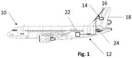
- Fig. 1 shows an aircraft 10 comprising a hydraulic system 12.
- the hydraulic system 12 comprises at least one consumer 14, such as a hydraulic actor 16 for driving movement of a component 18 of the aircraft 10. It is clear that the hydraulic system 12 may comprise several consumers 14, e.g. a plurality of actors 16 for driving different movements of one or several components 18. Each consumer 14 may be controlled by a hydraulic consumer control 20. Further, the hydraulic system 12 comprises at least one hydraulic power generating apparatus 22 for providing the at least one consumer 14 with hydraulic power. The at least one consumer 14 is connected to the hydraulic power generating apparatus 22 via hydraulic lines 24.
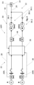
- Figs. 2 to 4 show block diagrams of the hydraulic system 12 including the hydraulic power generating apparatus 22.
- the hydraulic power generating apparatus 22 may be an electro-hydraulic system or a hydraulic power pack HPP.
- the hydraulic power generating apparatus 22 comprises a first electrical power source A and a first electrically driven motor pump MPU1 electrically powered by the first electrical power source A,
- the hydraulic power generating apparatus 22 may comprise more than two motor pump units and/or more than two electrical power sources.
- the electrical power sources A, B may comprise a generator G for converting mechanical energy into electricity and/or any other sources of electrical energy such a battery, PV cells, fuel cells, super caps, energy harvester, ...
- the hydraulic power generating apparatus 22 comprises a E-power determining device 28 for determining the actual available electrical power APA of the first electrical power source A and for determining the actual available electrical power APB of the second electrical power source B.
- the hydraulic power generation control 26 receives the information from the actual available electrical powers ABA; APB from the E-power determining device 28.
- the hydraulic system 12 comprises a hydraulic load sensing device 30 for sensing the actual hydraulic load 32 of the hydraulic system 10.
- the actual hydraulic load 32 may be sensed individually for each consumer 14 or total for the load at the output of the HPP, for example at the supply hydraulic line 24.
- Each motor pump MPU1, MPU2 comprises an electric motor M and a hydraulic pump P driven by the motor M. Further, the motor pump unit constituting the respective motor pumps MPU1, MPU2 may comprise a motor control 44 (especially with a frequency converter) controlling the electric motor M.
- the first motor pump MPU1 with its motor control 44 constitutes a first drive chain 36-1
- the second motor pump MPU2 with its motor control 44 constitutes a second drive chain 36-2.
- the outputs 38-1, 38-2 of the first and second drive chains 36-1, 36-2 are both connected to the hydraulic supply line 24 for supplying the at least one consumer 14 with hydraulic power.
- the hydraulic power generation control 26 receives the information about the actual hydraulic load 32 and the hydraulic power demand 33 of the at least one consumer 14 from the hydraulic load sensing device 30.
- the hydraulic power generation control 26 is configured to control the motor pumps MPU1, MPU2.
- the hydraulic power generation control 26 comprises a decision logic to determine a load factor UPA, UPB for each of the motor pumps and to supply the motor pumps MPU1, MPU2 with electric power in accordance with the determined load factors UPA, UPB.
- the load factor UPA, UPB for each motor pump is determined depending from the actual available power APA, APB of each of the electric sources A, B, from the hydraulic load 32 and the demand 33, and from status and conditions of the motor pumps MPU1, MPU2, especially previous load conditions and the load history thereof.
- the hydraulic power generation control 26 comprises a control logic configured to shift power from one of the drive chains 36-1 with low available power to a drive chain 36-2 with sufficient available power.
- Possible exemplary operation scenarios of the hydraulic system 12 and the hydraulic power generating apparatus 22 are indicated in the following tables 1 and 2.
- the electrical power sources A, B both supply enough electrical power for operating the at least one consumer 14.
- the electrical power sources A, B may be redundant power sources.
- Table 2 shows an abnormal or emergency operation, for example where one of the power sources A, B is not able to supply full energy or is even unavailable or where special demands arise.
- the available powers APA, APB, the load factors UPA, UPB and demands 33 are given in percent of their nominal values.
- Table 1 - Normal operation e.g.
- Fig. 2 shows the hydraulic system 12 in case 1.
- the hydraulic power generating control 26 sets the load factor UPA for the first motor pump MPU1 to 20%, and the load factor UPB for the second motor pump MPU2 to 80%.
- the power is shifted more to the second motor pump MPU2. This is especially advantageous, when the first motor pump MPU1 had a higher load or longer operation time before.
- the power may also be shifted equally (case 2 and case 4).
- the motor pumps MPU1, MPU2 may also be used in an alternating manner, e.g. the first motor pump MPU1 is used in a first flight, and the second motor pump MPU2 is used in a following second flight. This is indicated in case 3.
- Fig. 3 shows the hydraulic system in case 7.
- the first electrical power source A is reduced and has an actual available power APA of 20%.
- the hydraulic power generation control 26 shifts a large part of the power to the second motor pump MPU2.
- the hydraulic power generating control 26 is connected to hydraulic consumer controls 20 in order to request a limiting of the overall target 40, here for example 70%.
- the hydraulic consumer controls 20 are configured such that they limit accordingly the maximum overall demand to 70%. This may be done by shedding non-essential operations and reduction or staggering or sequencing of the remaining operations.
- Fig. 4 shows the hydraulic system 12 in case 8.
- the hydraulic power generating control 26 receives a very high demand 33 from the hydraulic consumer controls 20 - indicated as boost request 42.
- boost request 42 Such a short-term consumer demand 33 greater than 100% of the nominal demand can be allocated to the hydraulic consumers 14 provided that the available electrical power APA, APB is sufficient.
- the motor pumps MPU1, MPU2 operate in a boost mode for such a short time scenario.
- a hydraulic power generation apparatus (22) for hydraulically powering at least one consumer (14) of a hydraulic system (12) of an aircraft (10) comprising:
- the hydraulic power generation control 26 may be implemented in software or hardware, on existing electronic control units, e.g. those of the motor controls, or on additional electronic control units.
Landscapes
- Engineering & Computer Science (AREA)
- Mechanical Engineering (AREA)
- General Engineering & Computer Science (AREA)
- Physics & Mathematics (AREA)
- Fluid Mechanics (AREA)
- Aviation & Aerospace Engineering (AREA)
- Automation & Control Theory (AREA)
- Chemical & Material Sciences (AREA)
- Analytical Chemistry (AREA)
- Fluid-Pressure Circuits (AREA)
Abstract
a first electrical power source (A) and a first electrically driven motor pump (MPU1) electrically powered by the first electrical power source (A),
a second electrical power source (B) and a second electrically driven motor pump (MPU2) electrically powered by the second electrical power source (B),
and a hydraulic power generation control (26) which controls a supply of electrical energy from the first and second electrical power sources (A, B) to the first and second motor pumps (MPU1, MPU2). The invention proposes to determine the actual available electrical power (APA, APB) of each of the first and second electrical power sources (A, B) and to set a load factor (UPA, UPB) of each motor pump (MPU1, MPU2) in order to share a load to generate hydraulic power demanded from the at least one consumer (14) between the first and second motor pumps (MPU1, MPU2), wherein each load factor is set depending from the actual available electrical power (APA, APB).
Description
- The invention relates to a hydraulic power generation apparatus for hydraulically powering at least one consumer of a hydraulic system of an aircraft. Further the invention relates to a method for operating a hydraulic system of an aircraft including controlling generation of hydraulic power. Still further, the invention relates to an aircraft having such a hydraulic system.
- An object of the invention is to increase availability and reliability of hydraulic power generated in an aircraft from electric energy.
- For achieving such object, the invention provides a hydraulic power generation apparatus according to
claim 1. Further, the invention provides a method and an aircraft as indicated in the further independent claims. - Advantageous embodiments are subject-matters of the dependent claims.
- The invention provides according to one aspect thereof a hydraulic power generation apparatus for hydraulically powering at least one consumer of a hydraulic system of an aircraft, comprising:
- a first electrical power source and a first electrically driven motor pump electrically powered by the first electrical power source,
- a second electrical power source and a second electrically driven motor pump electrically powered by the second electrical power source,
- and a hydraulic power generation control which controls a supply of electrical energy from the first and second electrical power sources to the first and second motor pumps,
- wherein the hydraulic power generation control is configured to determine the actual available electrical power of each of the first and second electrical power sources and to set a load factor of each motor pump in order to share a load to generate hydraulic power demanded from the at least one consumer between the first and second motor pumps, wherein each load factor is set depending from the actual available electrical power.
- Preferably, the hydraulic power generation control is configured to set the load factors depending from a previous load condition of the first and second power source and/or of the first and second motor pump.
- Preferably, the hydraulic power generation control is configured to set the load factors such that, in a first operation interval, the first motor pump has a higher load as the second motor pump and, in a subsequent second operation interval, the first motor pump has a lower load as the second motor pump.
- Preferably, the hydraulic power generation control is configured to inform the at least one consumer about an actual available maximum power and to request the at least one consumer to limit the demand accordingly.
- Preferably, the hydraulic power generation control is configured to conduct the control such that the first and second power motors are used alternatively.
- Preferably, the hydraulic power generation control is configured to allow a boost mode of the at least one consumer depending from the actual available power, and to control the first and second motor such that a power over a nominal power is generated in reply to a boost demand.
- According to a further aspect, the invention provides a method of operating an hydraulic system of an aircraft, wherein the hydraulic system comprises
- a first electrical power source and a first electrically driven motor pump electrically powered by the first electrical power source,
- a second electrical power source and a second electrically driven motor pump electrically powered by the second electrical power source, and at least one consumer to be powered hydraulically, the method comprising the steps:
- a) determining the actual available electrical power of each of the first and second electrical power sources and
- b) setting a load factor of each motor pump in order to share a load to generate hydraulic power demanded from the at least one consumer between the first and second motor pumps, wherein each load factor is set depending from the actual available electrical power.
- Preferably, the load factors are set in step b) depending from at least one or several of:
- b1) a previous load condition of the first and second pump motors,
- b2) a previous load condition of the first and second power sources, and
- b3) power demand of the at least one consumer.
- Preferably, step b) comprises:
- b4) setting the load factors such that, in a first operation interval, the first motor pump has a higher load as the second motor pump and, in a subsequent second operation interval, the first motor pump has a lower load as the second motor pump.
- Preferably, the method comprises the further step:
limiting demands or allowing higher demands from the at least one consumer in response to the determined actual available electrical power of the first and second power sources. - Preferably, the first and second power motors are used alternatively in subsequent operation intervals.
- According to another aspect, the invention provides an aircraft, comprising a hydraulic system having at least one consumer and a hydraulic power generation apparatus according to any of the aforementioned embodiments.
- The invention relates to the field of hydraulic fluid systems. Preferred uses of embodiments of the invention are future aircraft projects that utilise hydraulic system(s) with hydraulic power packs (HPPs) and/or electro-hydraulic systems.
- Preferred embodiments of the invention relate to an aircraft hydraulic power pack active power shifting.
- Preferably, the hydraulic power generating apparatus is a hydraulic power pack for an aircraft. A hydraulic power pack normally includes one or two or more motor pump units (MPUs). Conventional hydraulic power packs may be powered electrically by an electrical power source. Embodiments of the invention include a hydraulic power pack (HPP) that has at least two motor pump units and is powered electrically by at least two electric power sources. The HPP is powering hydraulically a system comprising or consisting of one or more consumers. Hence, embodiments of the invention relate to HPP(s) with two or more motor pump units and supplied by more than one electric power source.
- The electric power source comprises of or several units of the group consisting of a battery, a battery pack, a mechanically driven generator, a fuel cell, a solar panel, an energy harvester, an array of super caps, and a photoelectric cell array.
- An advantage of the preferred embodiments of the invention is that in case of loss or limited available electric power the intended function of the hydraulic consumer(s) can be maintained at full performance or with limited performance. Loss of the hydraulic system is thereby prevented.
- In preferred embodiments, the electric loads in the power network can be balanced considering individual generator load situations across the aircraft. This can prevent generator overloads or bundle loads according to needs.
- In some embodiments, hydraulic output load control systems (i.e. consumer controls) can be requested to arrange themselves in such a way (e.g. by shedding of non-essential operations and reduction or staggering/sequencing of the remaining operations) that a required target (demand) is not exceeded.
- Usage of preferred embodiments reduce wear of the hydraulic power generation drives and will therefore increase availability and reliability as the hydraulic load on the drive-chain (i.e. Motor-Pump-Unit including Motor Control Electronic) is reduced - e.g., the Motor-Pump Units can be used in alternating sequence (e.g. one per flight).
- Most preferred embodiments refer to HPP(s) with two or more Motor-Pump Units and supplied by more than one electric power sources.
- Preferred embodiments include means having the following functionality:
The means is based on - 1) a determining unit sensing of available electrical power of each electrical source (in realtime).
- 2) a decision logic determining a load factor of each individual drive-chain (i.e. Motor-Pump-Unit including Motor Control Electronic). The load factor represents a means to allocate available power to a given drive chain in respect to its rated power.
- 3) a control logic shifting power from a drive-chain with low available power to a drive-chain with sufficient available power. "Shifting" thereby means not only an "on/off"- characteristic but an adapted power load ratio (example: 20% power at
MPU - 4) preferably, existing Motor Control Electronics is used and relevant criteria/parameter from the electrical network (e.g.available power at power source) is added.
- In some embodiments, the following function can be implemented additionally: Short term consumer demands greater than 100% of the nominal demand can be allocated to the hydraulic power consumers provided the available electrical power is sufficient. The MPU can be operated in a "boost mode" for such a short term scenario.
- Some embodiments of the preferred method comprise at least one, several or all of the following features/steps:
- 1) The following parameters will be recorded/evaluated in realtime/continuous:
- Available power in electric power network
- power demand in hydraulic system
- adaptations of power transfer from electrical available power through the electro-hydraulic drive chain to hydraulic power consumers (demands).
- 2) In adapted/calculated intervals: Status/Condition of MPU/MCE will be taken into account - balance wear/lifecycle,
e.g. MPU 1 is run inflight 1, MPU 2 is run in flight 2. In case of emergency the inactive MPU can be used in addition. - In some embodiments, in case of low electric power supply the nominal hydraulic system pressure can be reduced/ adapted to allow high flow (i.e. high actuator deflection rates)/ low pressure/force conditions. This feature can be used also for low load conditions, such as pre-flight check of flight control actuators on ground.
- Embodiments of the invention are explained below referring to the accompanying drawings in which:
- Fig. 1
- is a schematical side view of an aircraft comprising a hydraulic system with at least one consumer and a hydraulic power generating apparatus;
- Fig. 2
- is a block diagram schematically illustrating the hydraulic system and the hydraulic power generating apparatus during a possible operation mode in a normal operation;
- Fig. 3
- is a block diagram schematically illustrating the hydraulic system and the hydraulic power generating apparatus during a possible operation mode in an abnormal operation;
- Fig. 4
- is a block diagram schematically illustrating the hydraulic system and the hydraulic power generating apparatus during a possible boost mode operation.
-
Fig. 1 shows anaircraft 10 comprising ahydraulic system 12. Thehydraulic system 12 comprises at least oneconsumer 14, such as ahydraulic actor 16 for driving movement of acomponent 18 of theaircraft 10. It is clear that thehydraulic system 12 may compriseseveral consumers 14, e.g. a plurality ofactors 16 for driving different movements of one orseveral components 18. Eachconsumer 14 may be controlled by ahydraulic consumer control 20. Further, thehydraulic system 12 comprises at least one hydraulicpower generating apparatus 22 for providing the at least oneconsumer 14 with hydraulic power. The at least oneconsumer 14 is connected to the hydraulicpower generating apparatus 22 viahydraulic lines 24. -
Figs. 2 to 4 show block diagrams of thehydraulic system 12 including the hydraulicpower generating apparatus 22. The hydraulicpower generating apparatus 22 may be an electro-hydraulic system or a hydraulic power pack HPP. - According to the embodiments shown the hydraulic
power generating apparatus 22 comprises a first electrical power source A and a first electrically driven motor pump MPU1 electrically powered by the first electrical power source A, - a second electrical power source B and a second electrically driven motor pump MPU2 electrically powered by the second electrical power source B,
- and a hydraulic
power generation control 26 which controls a supply of electrical energy from the first and second electrical power sources A, B to the first and second motor pumps MPU1, MPU2. - Although not shown, the hydraulic
power generating apparatus 22 may comprise more than two motor pump units and/or more than two electrical power sources. - The electrical power sources A, B may comprise a generator G for converting mechanical energy into electricity and/or any other sources of electrical energy such a battery, PV cells, fuel cells, super caps, energy harvester, ...
- Further, the hydraulic
power generating apparatus 22 comprises a E-power determiningdevice 28 for determining the actual available electrical power APA of the first electrical power source A and for determining the actual available electrical power APB of the second electrical power source B. The hydraulicpower generation control 26 receives the information from the actual available electrical powers ABA; APB from theE-power determining device 28. - Further, the
hydraulic system 12 comprises a hydraulicload sensing device 30 for sensing the actualhydraulic load 32 of thehydraulic system 10. The actualhydraulic load 32 may be sensed individually for eachconsumer 14 or total for the load at the output of the HPP, for example at the supplyhydraulic line 24. - Each motor pump MPU1, MPU2 comprises an electric motor M and a hydraulic pump P driven by the motor M. Further, the motor pump unit constituting the respective motor pumps MPU1, MPU2 may comprise a motor control 44 (especially with a frequency converter) controlling the electric motor M. The first motor pump MPU1 with its
motor control 44 constitutes a first drive chain 36-1, and the second motor pump MPU2 with itsmotor control 44 constitutes a second drive chain 36-2. The outputs 38-1, 38-2 of the first and second drive chains 36-1, 36-2 are both connected to thehydraulic supply line 24 for supplying the at least oneconsumer 14 with hydraulic power. - The hydraulic
power generation control 26 receives the information about the actualhydraulic load 32 and thehydraulic power demand 33 of the at least oneconsumer 14 from the hydraulicload sensing device 30. The hydraulicpower generation control 26 is configured to control the motor pumps MPU1, MPU2. - In order to control the motor pumps MPU1, MPU2, the hydraulic
power generation control 26 comprises a decision logic to determine a load factor UPA, UPB for each of the motor pumps and to supply the motor pumps MPU1, MPU2 with electric power in accordance with the determined load factors UPA, UPB. - The load factor UPA, UPB for each motor pump is determined depending from the actual available power APA, APB of each of the electric sources A, B, from the
hydraulic load 32 and thedemand 33, and from status and conditions of the motor pumps MPU1, MPU2, especially previous load conditions and the load history thereof. - The hydraulic
power generation control 26 comprises a control logic configured to shift power from one of the drive chains 36-1 with low available power to a drive chain 36-2 with sufficient available power. - Possible exemplary operation scenarios of the
hydraulic system 12 and the hydraulicpower generating apparatus 22 are indicated in the following tables 1 and 2. In a normal operation, as shown in the table 1, the electrical power sources A, B, both supply enough electrical power for operating the at least oneconsumer 14. The electrical power sources A, B may be redundant power sources. Table 2 shows an abnormal or emergency operation, for example where one of the power sources A, B is not able to supply full energy or is even unavailable or where special demands arise. The available powers APA, APB, the load factors UPA, UPB and demands 33 are given in percent of their nominal values.Table 1 - Normal operation, e.g. (%) APA/APB UPA/ UPB Demand case 1 100/100 20/80 100 shared asymmetrically, full demand case 2 100/100 50/50 100 shared equally, full demand case 3 100/100 0/50 50 single source (e.g. alternating) case 4 100/100 25/25 50 shared equally, low demand Table 2 - Abnormal/Emergency operation, e.g. (%) APA/APB UPA/UPB Demand case 5 50/100 30/70 100 source A reduced, full demand case 6 0/100 0/100 100 source A unavailable, full demand case 7 20/50 20/50 70* both sources reduced, demand limited case 8 100/100 70/60 130** both sources available, very high demand (boost) * consumer system controls are requested to reduce overall power demands (e.g. shed, sequence, reduce)
"consumer system controls request a power boost (e.g. during specific manoeuvre) -
Fig. 2 shows thehydraulic system 12 incase 1. The hydraulicpower generating control 26 sets the load factor UPA for the first motor pump MPU1 to 20%, and the load factor UPB for the second motor pump MPU2 to 80%. Hence, the power is shifted more to the second motor pump MPU2. This is especially advantageous, when the first motor pump MPU1 had a higher load or longer operation time before. The power may also be shifted equally (case 2 and case 4). The motor pumps MPU1, MPU2 may also be used in an alternating manner, e.g. the first motor pump MPU1 is used in a first flight, and the second motor pump MPU2 is used in a following second flight. This is indicated in case 3. -
Fig. 3 shows the hydraulic system in case 7. In this example, the first electrical power source A is reduced and has an actual available power APA of 20%. The hydraulicpower generation control 26 shifts a large part of the power to the second motor pump MPU2. - The hydraulic
power generating control 26 is connected to hydraulic consumer controls 20 in order to request a limiting of theoverall target 40, here for example 70%. The hydraulic consumer controls 20 are configured such that they limit accordingly the maximum overall demand to 70%. This may be done by shedding non-essential operations and reduction or staggering or sequencing of the remaining operations. -
Fig. 4 shows thehydraulic system 12 in case 8. The hydraulicpower generating control 26 receives a veryhigh demand 33 from the hydraulic consumer controls 20 - indicated asboost request 42. Such a short-term consumer demand 33 greater than 100% of the nominal demand can be allocated to thehydraulic consumers 14 provided that the available electrical power APA, APB is sufficient. In such case, the motor pumps MPU1, MPU2 operate in a boost mode for such a short time scenario. - Accordingly, a hydraulic power generation apparatus (22) for hydraulically powering at least one consumer (14) of a hydraulic system (12) of an aircraft (10) has been described, comprising:
- a first electrical power source (A) and a first electrically driven motor pump (MPU1) electrically powered by the first electrical power source (A),
- a second electrical power source (B) and a second electrically driven motor pump (MPU2) electrically powered by the second electrical power source (B),
- and a hydraulic power generation control (26) which controls a supply of electrical energy from the first and second electrical power sources (A, B) to the first and second motor pumps (MPU1, MPU2),
- wherein the hydraulic power generation control (26) is configured to determine the actual available electrical power (APA, APB) of each of the first and second electrical power sources (A, B) and to set a load factor (UPA, UPB) of each motor pump (MPU1, MPU2) in order to share a load to generate hydraulic power demanded from the at least one consumer (14) between the first and second motor pumps (MPU1, MPU2), wherein each load factor is set depending from the actual available electrical power (APA, APB).
- The hydraulic
power generation control 26 may be implemented in software or hardware, on existing electronic control units, e.g. those of the motor controls, or on additional electronic control units. - Further, a method of operating a hydraulic system (12) of an aircraft (10) has been described, the hydraulic system (12) comprising
- a first electrical power source (A) and a first electrically driven motor pump (MPU1) electrically powered by the first electrical power source (A),
- a second electrical power source (B) and a second electrically driven motor pump (MPU2) electrically powered by the second electrical power source (B), and at least one consumer (14) to be powered hydraulically, the method comprising the steps:
- a) determining the actual available electrical power (APA, APB) of each of the first and second electrical power sources (A, B) and
- b) setting a load factor (UPA, UPB) of each motor pump (MPU1, MPU2) in order to share a load to generate hydraulic power demanded from the at least one consumer (14) between the first and second motor pumps (MPU1, MPU2), wherein each load factor (UPA, UPB) is set depending from the actual available electrical power (APA, APB).
-
- 10
- aircraft
- 12
- hydraulic system
- 14
- consumer
- 16
- actor
- 18
- com ponent
- 20
- hydraulic consumer control
- 22
- hydraulic power generating apparatus
- 24
- hydraulic line
- 26
- hydraulic power generation control
- 28
- E-power determining device
- 30
- hydraulic load sensing device
- 32
- hydraulic load
- 33
- hydraulic power demand
- 36-1
- first drive chain
- 36-2
- second drive chain
- 38-1
- output first drive chain
- 38-2
- output second drive chain
- 40
- limited overall target
- 42
- boost request
- 44
- motor control
- A
- first electrical power source
- APA
- actual available power of the first electrical power source
- APB
- actual available power of the second electrical power source
- B
- second electrical power source
- G
- generator
- HPP
- hydraulic power pack
- M
- (electric) motor
- MPU1
- first motor pump
- MPU2
- second motor pump
- P
- pump
- UPA
- load factor for first motor pump
- UPB
- load factor for second motor pump
Claims (12)
- Hydraulic power generation apparatus (22) for hydraulically powering at least one consumer (14) of a hydraulic system (12) of an aircraft (10), comprising:a first electrical power source (A) and a first electrically driven motor pump (MPU1) electrically powered by the first electrical power source (A),a second electrical power source (B) and a second electrically driven motor pump (MPU2) electrically powered by the second electrical power source (B),and a hydraulic power generation control (26) which controls a supply of electrical energy from the first and second electrical power sources (A, B) to the first and second motor pumps (MPU1, MPU2),wherein the hydraulic power generation control (26) is configured to determine the actual available electrical power (APA, APB) of each of the first and second electrical power sources (A, B) and to set a load factor (UPA, UPB) of each motor pump (MPU1, MPU2) in order to share a load to generate hydraulic power demanded from the at least one consumer (14) between the first and second motor pumps (MPU1, MPU2), wherein each load factor is set depending from the actual available electrical power (APA, APB).
- Hydraulic power generation apparatus (22) according to claim 1, characterized in that the hydraulic power generation control (26) is configured to set the load factors (APA, APB) in response to a previous load condition2.1 of the first and second power source (A, B) and/or2.2 of the first and second motor pump (MPU1, MPU2).
- Hydraulic power generation apparatus (22) according to any of the preceding claims, characterized in that the hydraulic power generation control (26) is configured to set the load factors (UPA, UPB) such that, in a first operation interval, the first motor pump (MPU1) has a higher load as the second motor pump (MPU2) and, in a subsequent second operation interval, the first motor pump (MPU1) has a lower load as the second motor pump (MPU2).
- Hydraulic power generation apparatus (22) according to any of the preceding claims, characterized in that hydraulic power generation control (26) is configured to inform the at least one consumer (14) about an actual available maximum power and to request the at least one consumer (14) to limit the overall demand accordingly.
- Hydraulic power generation apparatus (22) according to any of the preceding claims, characterized in that the hydraulic power generation control (26) is configured to conduct the control such that the first and second power motors (MPU1, MPU2) are used alternatively.
- Hydraulic power generation apparatus (22) according to any of the preceding claims, characterized in that the hydraulic power generation control (26) is configured to allow a boost mode of the at least one consumer (14) depending from the actual available power, and to control the first and second motor (MPU1, MPU2) such that an overall hydraulic power over a nominal overall hydraulic power is generated in reply to a boost demand.
- Method of operating a hydraulic system (12) of an aircraft (10), the hydraulic system (12) comprisinga first electrical power source (A) and a first electrically driven motor pump (MPU1) electrically powered by the first electrical power source (A),a second electrical power source (B) and a second electrically driven motor pump (MPU2) electrically powered by the second electrical power source (B), andat least one consumer (14) to be powered hydraulically, the method comprising the steps:a) determining the actual available electrical power (APA, APB) of each of the first and second electrical power sources (A, B) andb) setting a load factor (UPA, UPB) of each motor pump (MPU1, MPU2) in order to share a load to generate hydraulic power demanded from the at least one consumer (14) between the first and second motor pumps (MPU1, MPU2), wherein each load factor (UPA, UPB) is set depending from the actual available electrical power (APA, APB).
- Method according to claim 7, characterized in that the load factors (UPA, UPB) are set in step b) depending from at least one or several of:b1) a previous load condition of the first and second pump motors (MPU1, MPU2),b2) a previous load condition of the first and second power sources (A, B), andb3) power demand (33) of the at least one consumer (14).
- Method according to claim 7 or 8, characterized in that step b) comprises:
b4) setting the load factors (UPA, UPB) such that, in a first operation interval, the first motor pump (MPU1) has a higher load as the second motor pump (MPU2) and, in a subsequent second operation interval, the first motor pump (MPU1) has a lower load as the second motor pump (MPU2). - Method according to any of the claims 7 to 9, characterized by limiting demands or allowing higher demands from the at least one consumer (14) in response to the determined actual available electrical power (APA, APB) of the first and second power sources (A, B).
- Method according to any of the claims 7 to 10, wherein the first and second motor pumps (MPU1, MPU2) are used alternatively in subsequent operation intervals.
- Aircraft (10), comprising a hydraulic system (12) having at least one consumer (14) and a hydraulic power generation apparatus (22) according to any of the claims 1 to 6.
Priority Applications (3)
| Application Number | Priority Date | Filing Date | Title |
|---|---|---|---|
| EP23165763.6A EP4438470A1 (en) | 2023-03-31 | 2023-03-31 | Method and apparatus for generating hydraulic power in an aircraft |
| CN202410364658.4A CN118728776A (en) | 2023-03-31 | 2024-03-28 | Hydraulic power generation device, method of operating a hydraulic system, and aircraft including a hydraulic system |
| US18/622,719 US12392360B2 (en) | 2023-03-31 | 2024-03-29 | Method and apparatus for generating hydraulic power in an aircraft |
Applications Claiming Priority (1)
| Application Number | Priority Date | Filing Date | Title |
|---|---|---|---|
| EP23165763.6A EP4438470A1 (en) | 2023-03-31 | 2023-03-31 | Method and apparatus for generating hydraulic power in an aircraft |
Publications (1)
| Publication Number | Publication Date |
|---|---|
| EP4438470A1 true EP4438470A1 (en) | 2024-10-02 |
Family
ID=86226745
Family Applications (1)
| Application Number | Title | Priority Date | Filing Date |
|---|---|---|---|
| EP23165763.6A Pending EP4438470A1 (en) | 2023-03-31 | 2023-03-31 | Method and apparatus for generating hydraulic power in an aircraft |
Country Status (3)
| Country | Link |
|---|---|
| US (1) | US12392360B2 (en) |
| EP (1) | EP4438470A1 (en) |
| CN (1) | CN118728776A (en) |
Citations (3)
| Publication number | Priority date | Publication date | Assignee | Title |
|---|---|---|---|---|
| US20140151501A1 (en) * | 2012-12-04 | 2014-06-05 | Sumitomo Precision Products Co., Ltd. | Electro hydrostatic actuator system for retracting/extending landing gear |
| US20220169367A1 (en) * | 2020-11-30 | 2022-06-02 | Eaton Intelligent Power Limited | Redundant hydraulic power pack architecture for aircraft main landing gear system |
| EP4105120A1 (en) * | 2020-03-17 | 2022-12-21 | Sumitomo Precision Products Co., Ltd. | Eha system for lifting/lowering landing gear |
Family Cites Families (8)
| Publication number | Priority date | Publication date | Assignee | Title |
|---|---|---|---|---|
| JP3862256B2 (en) * | 2000-05-19 | 2006-12-27 | 株式会社小松製作所 | Hybrid machine with hydraulic drive |
| DE60141137D1 (en) * | 2000-05-23 | 2010-03-11 | Kobelco Constr Machinery Ltd | CONSTRUCTION MACHINE |
| JP3969068B2 (en) * | 2001-11-21 | 2007-08-29 | コベルコ建機株式会社 | Actuator drive device for hybrid work machine |
| DE102009019564A1 (en) * | 2009-05-02 | 2010-11-11 | Voith Patent Gmbh | Pumping method for providing predetermined total flow rate of hydraulic fluid by selectable total pressure, involves operating main supply pump by speed regulating electrical main drive |
| DE102011108535A1 (en) * | 2011-07-26 | 2013-01-31 | Airbus Operations Gmbh | Hydraulic motor-pump assembly and hydraulic system for a vehicle |
| CA3005441C (en) * | 2015-11-17 | 2023-09-26 | Transocean Innovation Labs Ltd | Reliability assessable systems for actuating hydraulically actuated devices and related methods |
| JP6596458B2 (en) * | 2017-03-13 | 2019-10-23 | 株式会社日立建機ティエラ | Hydraulic drive device for electric hydraulic work machine |
| US20220098832A1 (en) * | 2020-09-28 | 2022-03-31 | Artisan Vehicle Systems, Inc. | Redundant Dual Pump Hydraulic System and Method for Electric Mining Machine |
-
2023
- 2023-03-31 EP EP23165763.6A patent/EP4438470A1/en active Pending
-
2024
- 2024-03-28 CN CN202410364658.4A patent/CN118728776A/en active Pending
- 2024-03-29 US US18/622,719 patent/US12392360B2/en active Active
Patent Citations (3)
| Publication number | Priority date | Publication date | Assignee | Title |
|---|---|---|---|---|
| US20140151501A1 (en) * | 2012-12-04 | 2014-06-05 | Sumitomo Precision Products Co., Ltd. | Electro hydrostatic actuator system for retracting/extending landing gear |
| EP4105120A1 (en) * | 2020-03-17 | 2022-12-21 | Sumitomo Precision Products Co., Ltd. | Eha system for lifting/lowering landing gear |
| US20220169367A1 (en) * | 2020-11-30 | 2022-06-02 | Eaton Intelligent Power Limited | Redundant hydraulic power pack architecture for aircraft main landing gear system |
Also Published As
| Publication number | Publication date |
|---|---|
| US20240328436A1 (en) | 2024-10-03 |
| US12392360B2 (en) | 2025-08-19 |
| CN118728776A (en) | 2024-10-01 |
Similar Documents
| Publication | Publication Date | Title |
|---|---|---|
| US10787271B2 (en) | System for redundant supply of kinetic energy to drive system of aircraft | |
| EP4044396A1 (en) | Failsafe battery storage system | |
| US10090676B2 (en) | Aircraft DC power distribution systems and methods | |
| US7513742B2 (en) | Pitch drive system for a wind turbine | |
| KR101171160B1 (en) | Hybrid power supply device and method of controlling hybrid power supply device | |
| US11381089B2 (en) | Electric power system and a method and equipment for controlling the same | |
| EP3495272B1 (en) | Power system architecture for aircraft with electrical actuation | |
| US8263276B1 (en) | Startup power control in a fuel cell system | |
| US8872392B1 (en) | Fuel cell control system | |
| US20130181687A1 (en) | Fault tolerant electric drive system | |
| CN111404399B (en) | power supply system | |
| CN105048886A (en) | Systems and methods for the control and operation of a parallel motor controller architecture | |
| JP2011025799A (en) | Power feeding system and electric propulsion ship | |
| US11322267B2 (en) | Fault tolerant turbine speed control system | |
| KR20180090673A (en) | Hybrid energy storage system | |
| EP4148253A1 (en) | Redundant electrically driven fuel and oil pumping system for gas turbine with bidirectional pump motor | |
| US20110018354A1 (en) | Power System And Control Method Thereof | |
| US12392360B2 (en) | Method and apparatus for generating hydraulic power in an aircraft | |
| EP2432097A2 (en) | Uninterruptible power supply system | |
| JP2009255637A (en) | Marine vessel propulsion system | |
| EP3459154B1 (en) | Power supply for an isolated network | |
| CN114278488B (en) | A hydraulic power generation system for wave energy power generation device | |
| KR102351597B1 (en) | Operating method of isolating shaft generator for additional system power supply | |
| US11394323B2 (en) | Generator control systems and methods | |
| JP4521259B2 (en) | Marine inverter device |
Legal Events
| Date | Code | Title | Description |
|---|---|---|---|
| PUAI | Public reference made under article 153(3) epc to a published international application that has entered the european phase |
Free format text: ORIGINAL CODE: 0009012 |
|
| STAA | Information on the status of an ep patent application or granted ep patent |
Free format text: STATUS: THE APPLICATION HAS BEEN PUBLISHED |
|
| AK | Designated contracting states |
Kind code of ref document: A1 Designated state(s): AL AT BE BG CH CY CZ DE DK EE ES FI FR GB GR HR HU IE IS IT LI LT LU LV MC ME MK MT NL NO PL PT RO RS SE SI SK SM TR |
|
| STAA | Information on the status of an ep patent application or granted ep patent |
Free format text: STATUS: REQUEST FOR EXAMINATION WAS MADE |
|
| 17P | Request for examination filed |
Effective date: 20250402 |
|
| STAA | Information on the status of an ep patent application or granted ep patent |
Free format text: STATUS: EXAMINATION IS IN PROGRESS |
|
| 17Q | First examination report despatched |
Effective date: 20250808 |
|
| GRAP | Despatch of communication of intention to grant a patent |
Free format text: ORIGINAL CODE: EPIDOSNIGR1 |
|
| STAA | Information on the status of an ep patent application or granted ep patent |
Free format text: STATUS: GRANT OF PATENT IS INTENDED |
|
| RIC1 | Information provided on ipc code assigned before grant |
Ipc: B64C 13/42 20060101AFI20260324BHEP Ipc: F04B 23/04 20060101ALI20260324BHEP Ipc: F04B 49/06 20060101ALI20260324BHEP Ipc: F15B 11/17 20060101ALI20260324BHEP Ipc: F04B 49/00 20060101ALI20260324BHEP Ipc: F04B 49/20 20060101ALI20260324BHEP Ipc: F04B 17/03 20060101ALI20260324BHEP Ipc: F15B 20/00 20060101ALN20260324BHEP Ipc: B64D 45/00 20060101ALN20260324BHEP |