EP4438445A1 - Car with under-door side members - Google Patents
Car with under-door side members Download PDFInfo
- Publication number
- EP4438445A1 EP4438445A1 EP24165415.1A EP24165415A EP4438445A1 EP 4438445 A1 EP4438445 A1 EP 4438445A1 EP 24165415 A EP24165415 A EP 24165415A EP 4438445 A1 EP4438445 A1 EP 4438445A1
- Authority
- EP
- European Patent Office
- Prior art keywords
- under
- door side
- side member
- car
- car according
- Prior art date
- Legal status (The legal status is an assumption and is not a legal conclusion. Google has not performed a legal analysis and makes no representation as to the accuracy of the status listed.)
- Pending
Links
Images


Classifications
-
- B—PERFORMING OPERATIONS; TRANSPORTING
- B62—LAND VEHICLES FOR TRAVELLING OTHERWISE THAN ON RAILS
- B62D—MOTOR VEHICLES; TRAILERS
- B62D21/00—Understructures, i.e. chassis frame on which a vehicle body may be mounted
- B62D21/02—Understructures, i.e. chassis frame on which a vehicle body may be mounted comprising longitudinally or transversely arranged frame members
-
- B—PERFORMING OPERATIONS; TRANSPORTING
- B62—LAND VEHICLES FOR TRAVELLING OTHERWISE THAN ON RAILS
- B62D—MOTOR VEHICLES; TRAILERS
- B62D25/00—Superstructure or monocoque structure sub-units; Parts or details thereof not otherwise provided for
- B62D25/02—Side panels
- B62D25/025—Side sills thereof
-
- B—PERFORMING OPERATIONS; TRANSPORTING
- B60—VEHICLES IN GENERAL
- B60K—ARRANGEMENT OR MOUNTING OF PROPULSION UNITS OR OF TRANSMISSIONS IN VEHICLES; ARRANGEMENT OR MOUNTING OF PLURAL DIVERSE PRIME-MOVERS IN VEHICLES; AUXILIARY DRIVES FOR VEHICLES; INSTRUMENTATION OR DASHBOARDS FOR VEHICLES; ARRANGEMENTS IN CONNECTION WITH COOLING, AIR INTAKE, GAS EXHAUST OR FUEL SUPPLY OF PROPULSION UNITS IN VEHICLES
- B60K1/00—Arrangement or mounting of electrical propulsion units
- B60K1/04—Arrangement or mounting of electrical propulsion units of the electric storage means for propulsion
-
- B—PERFORMING OPERATIONS; TRANSPORTING
- B60—VEHICLES IN GENERAL
- B60K—ARRANGEMENT OR MOUNTING OF PROPULSION UNITS OR OF TRANSMISSIONS IN VEHICLES; ARRANGEMENT OR MOUNTING OF PLURAL DIVERSE PRIME-MOVERS IN VEHICLES; AUXILIARY DRIVES FOR VEHICLES; INSTRUMENTATION OR DASHBOARDS FOR VEHICLES; ARRANGEMENTS IN CONNECTION WITH COOLING, AIR INTAKE, GAS EXHAUST OR FUEL SUPPLY OF PROPULSION UNITS IN VEHICLES
- B60K11/00—Arrangement in connection with cooling of propulsion units
- B60K11/02—Arrangement in connection with cooling of propulsion units with liquid cooling
-
- B—PERFORMING OPERATIONS; TRANSPORTING
- B60—VEHICLES IN GENERAL
- B60R—VEHICLES, VEHICLE FITTINGS, OR VEHICLE PARTS, NOT OTHERWISE PROVIDED FOR
- B60R16/00—Electric or fluid circuits specially adapted for vehicles and not otherwise provided for; Arrangement of elements of electric or fluid circuits specially adapted for vehicles and not otherwise provided for
- B60R16/02—Electric or fluid circuits specially adapted for vehicles and not otherwise provided for; Arrangement of elements of electric or fluid circuits specially adapted for vehicles and not otherwise provided for electric constitutive elements
- B60R16/0207—Wire harnesses
- B60R16/0215—Protecting, fastening and routing means therefor
-
- B—PERFORMING OPERATIONS; TRANSPORTING
- B60—VEHICLES IN GENERAL
- B60R—VEHICLES, VEHICLE FITTINGS, OR VEHICLE PARTS, NOT OTHERWISE PROVIDED FOR
- B60R16/00—Electric or fluid circuits specially adapted for vehicles and not otherwise provided for; Arrangement of elements of electric or fluid circuits specially adapted for vehicles and not otherwise provided for
- B60R16/08—Electric or fluid circuits specially adapted for vehicles and not otherwise provided for; Arrangement of elements of electric or fluid circuits specially adapted for vehicles and not otherwise provided for fluid
-
- B—PERFORMING OPERATIONS; TRANSPORTING
- B60—VEHICLES IN GENERAL
- B60H—ARRANGEMENTS OF HEATING, COOLING, VENTILATING OR OTHER AIR-TREATING DEVICES SPECIALLY ADAPTED FOR PASSENGER OR GOODS SPACES OF VEHICLES
- B60H1/00—Heating, cooling or ventilating devices
- B60H1/00507—Details, e.g. mounting arrangements, desaeration devices
- B60H1/00557—Details of ducts or cables
- B60H1/00564—Details of ducts or cables of air ducts
-
- B—PERFORMING OPERATIONS; TRANSPORTING
- B60—VEHICLES IN GENERAL
- B60K—ARRANGEMENT OR MOUNTING OF PROPULSION UNITS OR OF TRANSMISSIONS IN VEHICLES; ARRANGEMENT OR MOUNTING OF PLURAL DIVERSE PRIME-MOVERS IN VEHICLES; AUXILIARY DRIVES FOR VEHICLES; INSTRUMENTATION OR DASHBOARDS FOR VEHICLES; ARRANGEMENTS IN CONNECTION WITH COOLING, AIR INTAKE, GAS EXHAUST OR FUEL SUPPLY OF PROPULSION UNITS IN VEHICLES
- B60K13/00—Arrangement in connection with combustion air intake or gas exhaust of propulsion units
- B60K13/06—Arrangement in connection with combustion air intake or gas exhaust of propulsion units using structural parts of the vehicle as ducts, e.g. frame parts
-
- B—PERFORMING OPERATIONS; TRANSPORTING
- B60—VEHICLES IN GENERAL
- B60K—ARRANGEMENT OR MOUNTING OF PROPULSION UNITS OR OF TRANSMISSIONS IN VEHICLES; ARRANGEMENT OR MOUNTING OF PLURAL DIVERSE PRIME-MOVERS IN VEHICLES; AUXILIARY DRIVES FOR VEHICLES; INSTRUMENTATION OR DASHBOARDS FOR VEHICLES; ARRANGEMENTS IN CONNECTION WITH COOLING, AIR INTAKE, GAS EXHAUST OR FUEL SUPPLY OF PROPULSION UNITS IN VEHICLES
- B60K1/00—Arrangement or mounting of electrical propulsion units
- B60K1/04—Arrangement or mounting of electrical propulsion units of the electric storage means for propulsion
- B60K2001/0405—Arrangement or mounting of electrical propulsion units of the electric storage means for propulsion characterised by their position
- B60K2001/0438—Arrangement under the floor
-
- B—PERFORMING OPERATIONS; TRANSPORTING
- B60—VEHICLES IN GENERAL
- B60Y—INDEXING SCHEME RELATING TO ASPECTS CROSS-CUTTING VEHICLE TECHNOLOGY
- B60Y2410/00—Constructional features of vehicle sub-units
- B60Y2410/115—Electric wiring; Electric connectors
Definitions
- the present invention relates to a car.
- the present invention relates to a car of the type comprising a support frame defining at least part of a lower floor of the car; a passenger compartment mounted on the support frame and protruding upwards from the lower floor; and a power engine for moving the car.
- the passenger compartment is provided with two access doors associated with respective under-door side members, which are commonly known by the term "sills", and define part of the support frame of the car.
- Each under-door side member extends under a relative access door, and is defined by a tubular section bar with an elongated shape normally having a quadrilateral, in particular square or rectangular, cross-section.
- the car further comprises a plurality of electrical wirings and a plurality of supply ducts of operating fluids mounted inside the passenger compartment.
- the known cars of the type described above have some drawbacks mainly deriving from the fact that the electrical wirings and the supply ducts are either mounted on the outside of, and along, the under-door side members thus reducing the space available inside the passenger compartment or are mounted on the inside of, and along, the under-door side members thus requiring relatively long and complex interventions by the qualified personnel.
- the object of the present invention is to provide a car which is exempt from the drawbacks described above and which is simple and cost-effective to manufacture.
- reference number 1 indicates, as a whole, a car, in particular a sports car, comprising a support frame 2 defining at least part of a lower floor 3 of the car 1, and a passenger compartment 4 mounted on the frame 2 and protruding upwards from the floor 3.
- the car 1 further comprises a power engine 5 of known type, which is mounted in the centre of a rear zone 6 of the frame 2, in particular parallel to a travel direction 7 of the car 1, and is connected in a known manner to two rear driving wheels 8 of the car 1.
- a power engine 5 of known type which is mounted in the centre of a rear zone 6 of the frame 2, in particular parallel to a travel direction 7 of the car 1, and is connected in a known manner to two rear driving wheels 8 of the car 1.
- the passenger compartment 4 is provided with two access doors 9, each of which extends above an under-door side member 10 with an elongated shape defining part of the frame 2.
- the side member 10 comprises a metal section bar 11, which is longitudinally delimited by two end faces 12, and is further laterally delimited by an outer surface 13.
- the side member 10 is provided with at least one longitudinal recess 14, which opens outwards in the area of the surface 13 for housing, on the inside, at least one electrical wiring 15 and/or at least one supply duct 16 for an operating fluid, for example for an air-conditioning system, for a braking system, for a cooling system of the car 1.
- the car 1 further comprises a power supply battery 17, which is fixed to the floor 3, and is thus rigidly connected to the side members 10 for guaranteeing a relatively high torsional stiffness to the assembly defined by the side members 10 and by the battery 17.
- the battery 17 is delimited, in this case, by two curved side faces 18, which face the corresponding side members 10, and have a bending that is complementary to the bending of the side members 10.
- each side member 10 is eliminated and replaced by a side member 19 comprising a metal section bar 20, which is longitudinally delimited by two end faces 21, and is further laterally delimited by an outer surface 22.
- the side member 19 comprises a first portion 23 having a quadrilateral cross-section, and a T-shaped second portion 24 protruding downwards from the portion 23.
- the portion 24 defines two longitudinal recesses 25, which open outwards in the area of the surface 22 for housing, on the inside, at least one electrical wiring 15 and/or at least one supply duct 16 for an operating fluid.
- the electrical wirings 15 and the supply ducts 16 are housed inside the recesses 14, 25 in a relatively simple manner and without occupying further space inside the passenger compartment 4.
Landscapes
- Engineering & Computer Science (AREA)
- Mechanical Engineering (AREA)
- Chemical & Material Sciences (AREA)
- Combustion & Propulsion (AREA)
- Transportation (AREA)
- Body Structure For Vehicles (AREA)
Abstract
Description
- This patent application claims priority from
Italian patent application no. 102023000005904 filed on March 28, 2023 - The present invention relates to a car.
- In particular, the present invention relates to a car of the type comprising a support frame defining at least part of a lower floor of the car; a passenger compartment mounted on the support frame and protruding upwards from the lower floor; and a power engine for moving the car.
- The passenger compartment is provided with two access doors associated with respective under-door side members, which are commonly known by the term "sills", and define part of the support frame of the car.
- Each under-door side member extends under a relative access door, and is defined by a tubular section bar with an elongated shape normally having a quadrilateral, in particular square or rectangular, cross-section.
- The car further comprises a plurality of electrical wirings and a plurality of supply ducts of operating fluids mounted inside the passenger compartment.
- The known cars of the type described above have some drawbacks mainly deriving from the fact that the electrical wirings and the supply ducts are either mounted on the outside of, and along, the under-door side members thus reducing the space available inside the passenger compartment or are mounted on the inside of, and along, the under-door side members thus requiring relatively long and complex interventions by the qualified personnel.
- The object of the present invention is to provide a car which is exempt from the drawbacks described above and which is simple and cost-effective to manufacture.
- According to the present invention, a car is provided as claimed in the appended claims.
- The present invention will now be described with reference to the accompanying drawings, which illustrate a non-limiting example embodiment thereof, wherein:
-
Figure 1 is a schematic perspective view, with parts removed for clarity, of a preferred embodiment of the car of the present invention; -
Figure 2 is a schematic perspective view, with parts removed for clarity, of a detail of the car ofFigure 1 ; and -
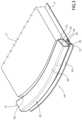
Figure 3 is a schematic perspective view, with parts removed for clarity, of a variation of the detail ofFigure 2 . - With reference to
Figures 1 and2 , reference number 1 indicates, as a whole, a car, in particular a sports car, comprising asupport frame 2 defining at least part of alower floor 3 of the car 1, and apassenger compartment 4 mounted on theframe 2 and protruding upwards from thefloor 3. - The car 1 further comprises a
power engine 5 of known type, which is mounted in the centre of arear zone 6 of theframe 2, in particular parallel to atravel direction 7 of the car 1, and is connected in a known manner to tworear driving wheels 8 of the car 1. - The
passenger compartment 4 is provided with twoaccess doors 9, each of which extends above an under-door side member 10 with an elongated shape defining part of theframe 2. - The
side member 10 comprises ametal section bar 11, which is longitudinally delimited by twoend faces 12, and is further laterally delimited by anouter surface 13. - The
side member 10 is provided with at least one longitudinal recess 14, which opens outwards in the area of thesurface 13 for housing, on the inside, at least oneelectrical wiring 15 and/or at least onesupply duct 16 for an operating fluid, for example for an air-conditioning system, for a braking system, for a cooling system of the car 1. - In this case:
- the recesses 14 further open outwards in the area of the
faces 12; - the
side member 10 is provided with two longitudinal recesses 14, of which one (in the following indicated by 14a) faces therecess 14a of the other side member 14 and the other one (in the following indicated by 14b) is opposite therecess 14a; - the
side member 10 has a curved shape with a concavity facing theother side member 10; and - the
section bar 11 of eachside member 10 is an H-shaped IPE beam. - The car 1 further comprises a
power supply battery 17, which is fixed to thefloor 3, and is thus rigidly connected to theside members 10 for guaranteeing a relatively high torsional stiffness to the assembly defined by theside members 10 and by thebattery 17. - The
battery 17 is delimited, in this case, by two curved side faces 18, which face thecorresponding side members 10, and have a bending that is complementary to the bending of theside members 10. - The variation illustrated in
Figure 3 differs from what is illustrated in the previous figures for the sole fact that, in said variation, eachside member 10 is eliminated and replaced by aside member 19 comprising a metal section bar 20, which is longitudinally delimited by twoend faces 21, and is further laterally delimited by anouter surface 22. - The
side member 19 comprises afirst portion 23 having a quadrilateral cross-section, and a T-shapedsecond portion 24 protruding downwards from theportion 23. - The
portion 24 defines twolongitudinal recesses 25, which open outwards in the area of thesurface 22 for housing, on the inside, at least oneelectrical wiring 15 and/or at least onesupply duct 16 for an operating fluid. - In this case:
- the
recesses 25 further open outwards in the area of thefaces 21; and - the
side member 19 has a curved shape with a concavity facing theother side member 19. - Since the
longitudinal recesses 14, 25 are open outwards in the area of theouter surfaces respective section bars 11, 20, theelectrical wirings 15 and thesupply ducts 16 are housed inside therecesses 14, 25 in a relatively simple manner and without occupying further space inside thepassenger compartment 4.
Claims (10)
- A car comprising a passenger compartment (4); two access doors (9) to access the passenger compartment (4); and a support frame (2), which defines a lower floor (3) of the car and comprises, in turn, two under-door side members (10; 19), each mounted under a relative access door (9) and comprising a section bar (11; 20) with an elongated shape, which is longitudinally delimited by two end faces (12; 21) and is laterally delimited by an outer surface (13; 22); and characterized in that at least one under-door side member (10; 19) comprises at least one longitudinal recess (14; 25), which opens outwards in the area of said outer surface (13; 22) and houses, on the inside, at least one electrical wiring (15) and/or at least one supply duct (16) for an operating fluid.
- The car according to claim 1, wherein each under-door side member (10; 19) comprises at least one longitudinal recess (14; 25).
- The car according to claim 1 or 2, wherein each longitudinal recess (14; 25) extends between the end faces (12; 21) of the section bar (11; 20) of the relative under-door side member (10; 19).
- The car according to any one of the preceding claims, wherein each under-door side member (10; 19) comprises a first longitudinal recess (14; 25) facing the first longitudinal recess (14; 25) of the other under-door side member (10; 19).
- The car according to claim 4, wherein each under-door side member (10; 19) comprises a second longitudinal recess (14; 25) opposite the relative first longitudinal recess (14; 25).
- The car according to any one of the preceding claims, wherein the section bar (11; 20) of each under-door side member (10; 19) has the shape of an IPE beam.
- The car according to any one of the preceding claims and further comprising a power supply battery (17) mounted between the two under-door side members (10; 19).
- The car according to claim 7, wherein the power supply battery (17) and the under-door side members (10; 19) are rigidly connected to one another.
- The car according to claim 7 or 8, wherein each under-door side member (10; 19) has a curved shape with a concavity facing the other under-door side member (10; 19) and the power supply battery (17) is delimited by two side faces (18) facing the under-door side members (10; 19) and having a bending that is complementary to the bending of the under-door side members (10; 19).
- The car according to any one of the preceding claims, wherein each longitudinal recess (14; 25) has a depth that is such as to house, on the inside, at least one electrical wiring (15) and/or at least one supply duct (16) for an operating fluid.
Applications Claiming Priority (1)
| Application Number | Priority Date | Filing Date | Title |
|---|---|---|---|
| IT102023000005904A IT202300005904A1 (en) | 2023-03-28 | 2023-03-28 | CAR WITH DOOR SIDES |
Publications (1)
| Publication Number | Publication Date |
|---|---|
| EP4438445A1 true EP4438445A1 (en) | 2024-10-02 |
Family
ID=86732623
Family Applications (1)
| Application Number | Title | Priority Date | Filing Date |
|---|---|---|---|
| EP24165415.1A Pending EP4438445A1 (en) | 2023-03-28 | 2024-03-22 | Car with under-door side members |
Country Status (4)
| Country | Link |
|---|---|
| US (1) | US20240326915A1 (en) |
| EP (1) | EP4438445A1 (en) |
| CN (1) | CN118722871A (en) |
| IT (1) | IT202300005904A1 (en) |
Citations (4)
| Publication number | Priority date | Publication date | Assignee | Title |
|---|---|---|---|---|
| KR100228094B1 (en) * | 1995-12-31 | 1999-11-01 | 정몽규 | Side seal full length wiring modular structure |
| US20170253271A1 (en) * | 2014-09-29 | 2017-09-07 | Matteo Bertezzolo | Adjustable chassis for a motor vehicle |
| CN111688819A (en) * | 2020-05-20 | 2020-09-22 | 浙江零跑科技有限公司 | Threshold structure of electric motor car |
| FR3110517A1 (en) * | 2020-05-25 | 2021-11-26 | Psa Automobiles Sa | MOTOR VEHICLE WITH ELECTRICAL HARNESS INTEGRATED IN A SIDE SKIRT |
Family Cites Families (5)
| Publication number | Priority date | Publication date | Assignee | Title |
|---|---|---|---|---|
| US1654033A (en) * | 1926-10-18 | 1927-12-27 | Lucius L Bishop | Luggage carrier |
| US11208044B2 (en) * | 2013-11-01 | 2021-12-28 | Lund Motion Products, Inc. | Remotely controlled vehicle step and lighting systems |
| US10814790B2 (en) * | 2018-06-26 | 2020-10-27 | Ford Global Technologies, Llc | Running board with roof access step and method |
| US10518727B1 (en) * | 2018-09-28 | 2019-12-31 | GM Global Technology Operations LLC | Step assembly for energy absorption |
| US11639135B2 (en) * | 2021-03-26 | 2023-05-02 | Toyota Motor Engineering & Manufacturing North America, Inc. | Vehicle rock slider with removable cover |
-
2023
- 2023-03-28 IT IT102023000005904A patent/IT202300005904A1/en unknown
-
2024
- 2024-03-22 US US18/614,073 patent/US20240326915A1/en active Pending
- 2024-03-22 EP EP24165415.1A patent/EP4438445A1/en active Pending
- 2024-03-26 CN CN202410350835.3A patent/CN118722871A/en active Pending
Patent Citations (4)
| Publication number | Priority date | Publication date | Assignee | Title |
|---|---|---|---|---|
| KR100228094B1 (en) * | 1995-12-31 | 1999-11-01 | 정몽규 | Side seal full length wiring modular structure |
| US20170253271A1 (en) * | 2014-09-29 | 2017-09-07 | Matteo Bertezzolo | Adjustable chassis for a motor vehicle |
| CN111688819A (en) * | 2020-05-20 | 2020-09-22 | 浙江零跑科技有限公司 | Threshold structure of electric motor car |
| FR3110517A1 (en) * | 2020-05-25 | 2021-11-26 | Psa Automobiles Sa | MOTOR VEHICLE WITH ELECTRICAL HARNESS INTEGRATED IN A SIDE SKIRT |
Also Published As
| Publication number | Publication date |
|---|---|
| CN118722871A (en) | 2024-10-01 |
| IT202300005904A1 (en) | 2024-09-28 |
| US20240326915A1 (en) | 2024-10-03 |
Similar Documents
| Publication | Publication Date | Title |
|---|---|---|
| US11097787B2 (en) | Lower vehicle-body structure | |
| CN109263455B (en) | front body structure | |
| US5464266A (en) | Motor vehicle with a stiff floor structure | |
| EP3536583B1 (en) | Vehicle | |
| US8973979B2 (en) | Bodywork | |
| US8029045B2 (en) | Crossbeam for a motor vehicle | |
| US20120153682A1 (en) | Single Piece Vehicle Rocker Panel | |
| US20110109122A1 (en) | Crash management system, and a method of making same | |
| WO2022192706A1 (en) | Multi-beam side frame assembly | |
| CN113135154A (en) | Vehicle structure | |
| CN103562055B (en) | Body of a motor car and its application | |
| CN104108429A (en) | Tunnel arrangement for a floor assembly of a vehicle body, and a floor assembly | |
| CN111824266B (en) | Side sill assembly for a motor vehicle | |
| EP0679564A1 (en) | A motor vehicle structure and a method for assembling a vehicle having this structure | |
| US20240075987A1 (en) | Vehicle front rail | |
| KR20220082488A (en) | Body of vehicle | |
| EP4438445A1 (en) | Car with under-door side members | |
| DE102019113701A1 (en) | Motor vehicle with an electric drive and a body-integrated storage cell assembly | |
| EP0678441B1 (en) | Equipment for assembling a plurality of subframes for motor cars | |
| US11760286B2 (en) | Bumper crossmember, and vehicle rear arrangement with bumper crossmember | |
| US20220111917A1 (en) | Modular vehicle body and method for manufacturing modular vehicle body | |
| WO2018188220A1 (en) | Vehicle body front floor assembly and electric vehicle | |
| CN212022569U (en) | Energy absorption box and car | |
| JP2021115964A (en) | Vehicle frame and vehicle | |
| EP4574494A1 (en) | Car with battery integrated in the under-door side members |
Legal Events
| Date | Code | Title | Description |
|---|---|---|---|
| PUAI | Public reference made under article 153(3) epc to a published international application that has entered the european phase |
Free format text: ORIGINAL CODE: 0009012 |
|
| STAA | Information on the status of an ep patent application or granted ep patent |
Free format text: STATUS: THE APPLICATION HAS BEEN PUBLISHED |
|
| AK | Designated contracting states |
Kind code of ref document: A1 Designated state(s): AL AT BE BG CH CY CZ DE DK EE ES FI FR GB GR HR HU IE IS IT LI LT LU LV MC ME MK MT NL NO PL PT RO RS SE SI SK SM TR |
|
| STAA | Information on the status of an ep patent application or granted ep patent |
Free format text: STATUS: REQUEST FOR EXAMINATION WAS MADE |
|
| 17P | Request for examination filed |
Effective date: 20250226 |
|
| GRAP | Despatch of communication of intention to grant a patent |
Free format text: ORIGINAL CODE: EPIDOSNIGR1 |
|
| STAA | Information on the status of an ep patent application or granted ep patent |
Free format text: STATUS: GRANT OF PATENT IS INTENDED |
|
| INTG | Intention to grant announced |
Effective date: 20260120 |