EP4438442A1 - Gear and steering device - Google Patents
Gear and steering device Download PDFInfo
- Publication number
- EP4438442A1 EP4438442A1 EP21965651.9A EP21965651A EP4438442A1 EP 4438442 A1 EP4438442 A1 EP 4438442A1 EP 21965651 A EP21965651 A EP 21965651A EP 4438442 A1 EP4438442 A1 EP 4438442A1
- Authority
- EP
- European Patent Office
- Prior art keywords
- gear
- circumferential direction
- installation location
- sleeve
- ribs
- Prior art date
- Legal status (The legal status is an assumption and is not a legal conclusion. Google has not performed a legal analysis and makes no representation as to the accuracy of the status listed.)
- Pending
Links
Images



Classifications
-
- F—MECHANICAL ENGINEERING; LIGHTING; HEATING; WEAPONS; BLASTING
- F16—ENGINEERING ELEMENTS AND UNITS; GENERAL MEASURES FOR PRODUCING AND MAINTAINING EFFECTIVE FUNCTIONING OF MACHINES OR INSTALLATIONS; THERMAL INSULATION IN GENERAL
- F16H—GEARING
- F16H55/00—Elements with teeth or friction surfaces for conveying motion; Worms, pulleys or sheaves for gearing mechanisms
- F16H55/02—Toothed members; Worms
- F16H55/06—Use of materials; Use of treatments of toothed members or worms to affect their intrinsic material properties
-
- B—PERFORMING OPERATIONS; TRANSPORTING
- B62—LAND VEHICLES FOR TRAVELLING OTHERWISE THAN ON RAILS
- B62D—MOTOR VEHICLES; TRAILERS
- B62D5/00—Power-assisted or power-driven steering
- B62D5/04—Power-assisted or power-driven steering electrical, e.g. using an electric servo-motor connected to, or forming part of, the steering gear
- B62D5/0442—Conversion of rotational into longitudinal movement
- B62D5/0454—Worm gears
-
- F—MECHANICAL ENGINEERING; LIGHTING; HEATING; WEAPONS; BLASTING
- F16—ENGINEERING ELEMENTS AND UNITS; GENERAL MEASURES FOR PRODUCING AND MAINTAINING EFFECTIVE FUNCTIONING OF MACHINES OR INSTALLATIONS; THERMAL INSULATION IN GENERAL
- F16H—GEARING
- F16H55/00—Elements with teeth or friction surfaces for conveying motion; Worms, pulleys or sheaves for gearing mechanisms
- F16H55/02—Toothed members; Worms
- F16H55/17—Toothed wheels
-
- F—MECHANICAL ENGINEERING; LIGHTING; HEATING; WEAPONS; BLASTING
- F16—ENGINEERING ELEMENTS AND UNITS; GENERAL MEASURES FOR PRODUCING AND MAINTAINING EFFECTIVE FUNCTIONING OF MACHINES OR INSTALLATIONS; THERMAL INSULATION IN GENERAL
- F16H—GEARING
- F16H55/00—Elements with teeth or friction surfaces for conveying motion; Worms, pulleys or sheaves for gearing mechanisms
- F16H55/02—Toothed members; Worms
- F16H55/22—Toothed members; Worms for transmissions with crossing shafts, especially worms, worm-gears
-
- B—PERFORMING OPERATIONS; TRANSPORTING
- B62—LAND VEHICLES FOR TRAVELLING OTHERWISE THAN ON RAILS
- B62D—MOTOR VEHICLES; TRAILERS
- B62D5/00—Power-assisted or power-driven steering
- B62D5/04—Power-assisted or power-driven steering electrical, e.g. using an electric servo-motor connected to, or forming part of, the steering gear
- B62D5/0409—Electric motor acting on the steering column
-
- F—MECHANICAL ENGINEERING; LIGHTING; HEATING; WEAPONS; BLASTING
- F16—ENGINEERING ELEMENTS AND UNITS; GENERAL MEASURES FOR PRODUCING AND MAINTAINING EFFECTIVE FUNCTIONING OF MACHINES OR INSTALLATIONS; THERMAL INSULATION IN GENERAL
- F16H—GEARING
- F16H55/00—Elements with teeth or friction surfaces for conveying motion; Worms, pulleys or sheaves for gearing mechanisms
- F16H55/02—Toothed members; Worms
- F16H55/06—Use of materials; Use of treatments of toothed members or worms to affect their intrinsic material properties
- F16H2055/065—Moulded gears, e.g. inserts therefor
Definitions
- the present invention relates to a gear and a steering system.
- a speed reducer for an automotive steering system including a worm and a gear serving as a worm wheel that meshes with the worm.
- a gear serving as a worm wheel that meshes with the worm.
- a disc-shaped resin sleeve and a resin toothing that covers the entire outer peripheral portion of the sleeve and has a plurality of gear teeth are integrally molded (see, for example, Patent Document 1).
- Patent Document 1 Japanese Unexamined Patent Application Publication No. 2017-82860 ( JP 2017-82860 A )
- a sleeve made of a reinforced resin material is first molded, and then a toothing is molded from a non-reinforced resin material with the sleeve inserted. At this time, it is necessary to increase the holding pressure in the mold in order to increase the accuracy of the gear teeth.
- the sleeve may be heated by the molten resin, the rigidity of the sleeve may decrease, and part of the sleeve may slightly be deformed due to thermal contraction. This deformation results in a decrease in gear accuracy (mesh runout).
- An object of the present invention is to suppress a decrease in gear accuracy.
- a gear according to one aspect of the present invention includes a resin sleeve having a disc shape, and a resin toothing that covers an outer peripheral portion of the sleeve and includes a plurality of gear teeth arranged at equal intervals in a circumferential direction.
- the sleeve includes a plurality of protrusions arranged on an outer peripheral surface at equal intervals in the circumferential direction, and a plurality of ribs arranged at equal intervals in the circumferential direction at positions on a radially inner side of the protrusions.
- a first installation location count of the protrusions in the circumferential direction and a second installation location count of the ribs in the circumferential direction are equal to each other and are integral multiples of a third installation location count of the gear teeth in the circumferential direction.
- a steering system includes an electric motor to be driven based on steering of a steering member, and a speed reducer including the above gear and configured to reduce a speed of output rotation of the electric motor by the gear and transmit the output rotation to a steering mechanism.
- an axial direction of a gear is defined as a Y-axis direction.
- the X-axis direction is a direction perpendicular to the Y-axis direction
- a Z-axis direction is a direction perpendicular to both the Y-axis direction and the X-axis direction.
- a positive X-axis direction indicates a side in an arrow direction of the X-axis
- a negative X-axis direction indicates a side opposite to the positive X-axis direction.
- the Y-axis direction and the Z-axis direction is defined as a Y-axis direction.
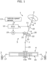
- FIG. 1 is a schematic diagram of a steering system 1 according to the embodiment.
- the steering system 1 is an electric power steering system that includes a steering mechanism 6 and a steering operation mechanism 4 and turns steered wheels 3 based on a driver's steering (steering operation) on a steering wheel 2 (steering member).
- the steering mechanism 6 includes an assist mechanism 5 that assists the driver's steering operation.
- the steering mechanism 6 includes an input shaft 8, an output shaft 9, an intermediate shaft 7, and a pinion shaft 15.
- the input shaft 8 is connected to the steering wheel 2.
- the output shaft 9 is connected to the input shaft 8 via a torsion bar 10.
- the intermediate shaft 7 is connected to the pinion shaft 15 including a pinion 15a via a universal joint.
- the steering operation mechanism 4 includes a rack shaft 16 and tie rods 17.
- the rack shaft 16 includes a rack 16a meshing with the pinion 15a.
- the tie rod 17 has one end connected to the rack shaft 16 and the other end connected to the steered wheel 3.
- the pinion shaft 15 rotates via the input shaft 8, the output shaft 9, and the intermediate shaft 7.
- the rotation of the pinion shaft 15 is converted by the steering operation mechanism 4 into reciprocating motion of the rack shaft 16 in the axial direction.
- the reciprocating motion of the rack shaft 16 in the axial direction changes the steered angles of the steered wheels 3.
- the assist mechanism 5 includes a torque sensor 11, an ECU (Electronic Control Unit) 12, an electric motor 19, and a speed reducer 20.
- the speed reducer 20 includes a worm 21, a gear 22 structured as a worm wheel meshing with the worm 21, and a housing 23 that houses the worm 21 and the gear 22.
- the worm 21 is connected to a rotary shaft (not shown) of the electric motor 19.
- the gear 22 is connected to the output shaft 9 so as to be rotatable together with the output shaft 9.
- the torque sensor 11 detects the amount of torsion between the input shaft 8 and the output shaft 9.
- the ECU 12 determines an assist torque based on a steering torque T obtained from the amount of torsion detected by the torque sensor 11, a vehicle speed V detected by a vehicle speed sensor 13, etc.
- the drive of the electric motor 19 is controlled by the ECU 12.
- the electric motor 19 driven in this manner based on the steering of the steering wheel 2 transmits output rotation to the worm 21 to rotate the worm 21 .
- the gear 22 meshing with the worm 21 rotates at a lower speed than that of the worm 21, and the gear 22 and the output shaft 9 rotate together.
- the speed reducer 20 reduces the speed of the output rotation of the electric motor 19 by using the gear 22 and transmits it to the output shaft 9 of the steering mechanism 6 as an assist torque.
- the driver's steering operation on the steering wheel 2 is assisted.
- FIG. 2 is a perspective view of the gear 22 according to the embodiment that is viewed from a front side.
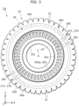
- FIG. 3 is a plan view of the front side of the gear 22 according to the embodiment.
- FIG. 4 is a plan view of a rear side of the gear 22 according to the embodiment.
- the outline of a sleeve 26 of the gear 22 is shown by a dashed line.
- the gear 22 has a disc shape.
- the Y-axis direction is the axial direction of the gear 22, and may also be a thickness direction of the gear 22.
- a central axis C of the gear 22 extends in the Y-axis direction through the center of a circle of the gear 22.
- a negative Y-axis direction is the front side of the gear 22, and a positive Y-axis direction is the rear side of the gear 22.
- the gear 22 has a circular through hole 221 extending through the center of the circle along the Y-axis direction.
- the output shaft 9 is press-fitted to the through hole 221, and therefore the gear 22 is connected to the output shaft 9 so as to be rotatable together with the output shaft 9.
- a plurality of gear teeth 31 meshing with the worm 21 is formed on the entire outer peripheral surface of the gear 22 and arranged at equal intervals in a circumferential direction of the gear 22.
- the installation location of each gear tooth 31 in the circumferential direction will be referred to as "third installation location".
- the third installation locations are arranged at equal intervals in the circumferential direction.
- the present embodiment illustrates a case where the total count of third installation locations (third installation location count N) is 41. It is only necessary that one gear tooth 31 be provided at each third installation location. However, two or more gear teeth 31 may be arranged in the axial direction (Y-axis direction) at one third installation location.
- the clearance between adjacent gear teeth 31 has a shape of a groove obtained by cutting out the outer peripheral portion of the gear 22 in the Y-axis direction.
- the gear 22 includes a collar 24, a toothing 25, and the sleeve 26.
- the collar 24 is a cylindrical metal member having a central axis that coincides with the central axis C.
- the through hole 221 of the gear 22 is defined by the inner peripheral surface of the collar 24.
- the toothing 25 is a resin member made of, for example, a non-reinforced resin and serving as the plurality of gear teeth 31.
- the toothing 25 has an annular shape and continuously covers an entire outer peripheral portion 262 of the sleeve 26.
- the plurality of gear teeth 31 is formed on the outer peripheral surface of the toothing 25.
- the sleeve 26 is a member coaxially fitted onto the collar 24.
- the sleeve 26 has a disc shape and is a resin member made entirely of a resin. More specifically, the sleeve 26 is made of a reinforced resin mixed with, for example, glass fiber.
- the sleeve 26 integrally includes an inner peripheral portion 261 positioned at the innermost side in a radial direction, the outer peripheral portion 262 portioned at the outermost side in the radial direction, and a connecting portion 263 that is disposed between the inner peripheral portion 261 and the outer peripheral portion 262 and connects the inner peripheral portion 261 and the outer peripheral portion 262.
- the inner peripheral portion 261 has an annular shape with a central axis that coincides with the central axis C.
- the collar 24 is fitted to the inner peripheral surface of the inner peripheral portion 261.
- the outer peripheral portion 262 has an annular shape and is disposed coaxially with the inner peripheral portion 261.
- a plurality of protrusions 264 that protrudes radially outward is formed on the outer peripheral surface of the outer peripheral portion 262 and arranged at equal intervals in the circumferential direction of the outer peripheral portion 262.
- the plurality of protrusions 264 is shown by dashed lines.
- a space between a pair of adj acent protrusions 264 will be referred to as "recess 265". Therefore, a plurality of recesses 265 is provided on the outer peripheral surface of the outer peripheral portion 262.
- the plurality of recesses 265 is arranged at equal intervals in the circumferential direction of the outer peripheral portion 262.
- first installation location The installation location of each protrusion 264 in the circumferential direction will be referred to as "first installation location".
- the first installation locations are arranged at equal intervals in the circumferential direction.
- the present embodiment illustrates a case where the total count of first installation locations (first installation location count L) is 41. It is only necessary that one protrusion 264 be provided at each first installation location. However, two or more protrusions 264 may be arranged in the axial direction (Y-axis direction) at one first installation location.
- the connecting portion 263 is an annular portion disposed between the inner peripheral portion 261 and the outer peripheral portion 262 so as to continuously connect the inner peripheral portion 261 and the outer peripheral portion 262 over the entire circumference.
- a plurality of ribs 270 is arranged in the connecting portion 263 at equal intervals in the circumferential direction. Since the connecting portion 263 is a portion on a radially inner side of the outer peripheral portion 262, the plurality of ribs 270 is disposed on a radially inner side of the plurality of protrusions 264.
- a plurality of first ribs 271 that is part of the plurality of ribs 270 is arranged at equal intervals in the circumferential direction on a first principal surface 263a on the front side of the connecting portion 263.
- a space between the plurality of first ribs 271 in the circumferential direction is a first hole 281. That is, the plurality of first ribs 271 and the plurality of first holes 281 are arranged alternately in the circumferential direction.
- the first holes 281 have the same shape in a plan view (as viewed in the Y-axis direction), and are long holes that are elongated in the radial direction.
- a plurality of second ribs 272 that is part of the plurality of ribs 270 is arranged at equal intervals in the circumferential direction on a second principal surface 263b on the rear side of the connecting portion 263.
- a space between the plurality of second ribs 272 in the circumferential direction is a second hole 282. That is, the plurality of second ribs 272 and the plurality of second holes 282 are arranged alternately in the circumferential direction.
- the second hole 282 and the first hole 281 are lightening holes for reducing the weight of the sleeve 26.
- the second holes 282 have the same shape as the first holes 281 in a plan view (as viewed in the Y-axis direction). Each second hole 282 is disposed at a position corresponding to each first hole 281. Therefore, each second rib 272 has the same shape as each first rib 271 and is disposed at a position corresponding to each first rib 271. That is, the corresponding first rib 271 and the corresponding second rib 272 are installed at the same installation location. This installation location will be referred to as "second installation location”. The second installation locations are arranged at equal intervals in the circumferential direction. It is only necessary that one set of the first rib 271 and the second rib 272 be provided at each second installation location.
- the present embodiment illustrates a case where the total count of second installation locations (second installation location count M) is 41. That is, the first installation location count L, the second installation location count M, and the third installation location count N are equal to each other.
- a mold is filled with a molten resin serving as the toothing 25 while the sleeve 26 molded first is disposed in the mold.
- the rigidity of the sleeve 26 may decrease due to heat from the molten resin and holding pressure in the mold, and some portions may slightly be deformed. Since the first installation location count L and the second installation location count M are equal to each other and a constant holding pressure is applied in the mold, the slightly deformed portions can be generated at synchronized positions in the circumferential direction for the protrusions 264 and the ribs 270.
- the slightly deformed portions of the sleeve 26 and the gear teeth 31 are present at synchronized positions in the circumferential direction. Therefore, even if each gear tooth 31 is also slightly deformed due to each slightly deformed portion of the sleeve 26, the deformed portion of each gear tooth 31 is also generated substantially at the same position. If a different portion is deformed in each gear tooth 31, a fluctuation in a period different from the meshing period may occur or undulations may occur in the rotation period. When the deformed portion of each gear tooth 31 is substantially at the same position as in the present embodiment, such troubles can be reduced.
- each recess 265 and each rib 270 each first rib 271 and each second rib 272 in the sleeve 26
- each first rib 271 and each second rib 272 have the same shape and are disposed at mutually corresponding positions. Therefore, description will be given taking the first rib 271 as an example and description of the second rib 272 will be omitted.
- the positional relationship between one recess 265 and one first rib 271 will be described as an example, and the same applies to the positional relationships between the other recesses 265 and the other first ribs 271.
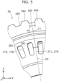
- FIG. 5 is a partial front view of part of the sleeve 26 according to the embodiment that is viewed from the front side.
- a central line C1 of the recess 265 in the circumferential direction coincides with a central line C2 of the first rib 271 in the circumferential direction (shown by a long dashed double-short dashed line).
- the central line C1 is a line that bisects a width H1 of the recess 265 in the circumferential direction, and is a straight line passing through the central axis C.
- the central line C2 is a line that bisects a width H2 of the first rib 271 in the circumferential direction, and is a straight line passing through the central axis C.
- the rigidity of each first rib 271 in the radial direction can be made as uniform as possible.
- the width H2 of the first rib 271 in the circumferential direction is preferably larger than the width H1 of the recess 265 in the circumferential direction. In this case, the rigidity of the first rib 271 in the circumferential direction can be increased. The same applies to each second rib 272.
- FIG. 6 is a partial sectional view of part of the toothing 25 and the sleeve 26 according to the embodiment that are viewed in the X-axis direction.
- FIG. 6 shows the positional relationship between one set of the first hole 281 and the second hole 282 and one gear tooth 31 corresponding to the set, and the same applies to the positional relationships between the other sets of the first hole 281 and the second hole 282 and the other gear teeth 31 corresponding to the other sets. As shown in FIG.
- a central line C3 between the first hole 281 and the second hole 282 as a set in the axial direction (Y-axis direction) (shown by a long dashed double-short dashed line) coincides with a central line C4 of the gear tooth 31 in the axial direction (shown by a long dashed short dashed line).
- the central line C3 is a line that bisects a length H3 in the Y-axis direction between the bottom of the first hole 281 and the bottom of the second hole 282, and is a straight line parallel to the Z-axis direction.
- the central line C4 is a line that bisects a length H4 of the gear tooth 31 in the Y-axis direction, and is a straight line parallel to the Z-axis direction.
- the first installation location count L, the second installation location count M, and the third installation location count N are equal to each other. Therefore, each portion of the sleeve 26 slightly deformed during the manufacturing and each gear tooth 31 are present at synchronized positions in the circumferential direction. Thus, even if each gear tooth 31 is also slightly deformed due to each slightly deformed portion of the sleeve 26, the deformed portion of each gear tooth 31 can also be generated substantially at the same position. Accordingly, the fluctuation in a period different from the meshing period and the undulations in the rotation period can be suppressed. As a result, a decrease in the accuracy of the gear 22 can be suppressed.
- the above embodiment illustrates the case where the first installation location count L and the second installation location count M are equal to the third installation location count N.
- the first installation location count L and the second installation location count M be equal to each other and be integral multiples of the third installation location count N.
- Q is an integer of N
- the deformed portion of each gear tooth 31 due to each slightly deformed portion of the sleeve 26 can be generated at a position that is close to some extent. That is, the decrease in the accuracy of the gear can be suppressed in this case as well.
- the above embodiment illustrates the case where the central line C1 of the recess 265 coincides with the central line C2 of the rib 270. However, it is only necessary that the central line C1 of the recess 265 be within the width of the rib 270 in the circumferential direction. In this case as well, the rigidity of each rib 270 in the radial direction can be made uniform to some extent.
- the above embodiment illustrates the case where the central line C3 between the first hole 281 and the second hole 282 in the axial direction coincides with the central line C4 of the gear tooth 31.
- the central line C4 of the gear tooth 31 be present between the first hole 281 and the second hole 282 in the axial direction.
- the tilting of the first rib 271 and the second rib 272 in the axial direction can be suppressed to some extent.
- first hole 281 and the second hole 282 as a set each have a bottomed shape.
- first hole 281 and the second hole 282 as a set may extend through their bottoms in the axial direction.
- the weight of the gear 22 can further be reduced.
- the above embodiment illustrates the case where the plurality of first ribs 271 is provided on the first principal surface 263a of the connecting portion 263 and the plurality of second ribs 272 is provided on the second principal surface 263b.
- the plurality of ribs may be provided only on one of the first principal surface and the second principal surface in the connecting portion.
- the above embodiment illustrates the case where the output shaft 9 is press-fitted to the through hole 221 of the collar 24 of the gear 22 to connect the gear 22 to the output shaft 9 so that the gear 22 is rotatable together with the output shaft 9.
- serrations may be provided on the inner peripheral surface of the collar and the outer peripheral surface of the output shaft, and the collar and the output shaft may be fitted with the serrations.
- the collar may be omitted from the gear.
- the sleeve is connected directly to the output shaft.
- the present invention also includes forms obtained by applying various modifications conceivable by those skilled in the art to the embodiment, or forms realized by arbitrarily combining the components and functions in the embodiment and modifications without departing from the spirit of the present invention.
- the present invention is applicable to a gear to be used in a speed reducer.
- outer peripheral portion 263 ... connecting portion, 263a ... first principal surface, 263b ... second principal surface, 264 ... protrusion, 265 ... recess, 270 ... rib, 271 ... first rib, 272 ... second rib, 281 ... first hole, 282 ... second hole, C ... central axis, C1, C2, C3, C4 ... central line, H1, H2 ... width, H3, H4 ... length, T ... steering torque, V ... vehicle speed
Landscapes
- Engineering & Computer Science (AREA)
- General Engineering & Computer Science (AREA)
- Mechanical Engineering (AREA)
- Chemical & Material Sciences (AREA)
- Combustion & Propulsion (AREA)
- Transportation (AREA)
- Physics & Mathematics (AREA)
- Electromagnetism (AREA)
- Thermal Sciences (AREA)
- Power Steering Mechanism (AREA)
- Gears, Cams (AREA)
Abstract
Description
- The present invention relates to a gear and a steering system.
- For example, there is known a speed reducer for an automotive steering system, including a worm and a gear serving as a worm wheel that meshes with the worm. In such a gear, a disc-shaped resin sleeve and a resin toothing that covers the entire outer peripheral portion of the sleeve and has a plurality of gear teeth are integrally molded (see, for example, Patent Document 1).
- Patent Document 1:
Japanese Unexamined Patent Application Publication No. 2017-82860 JP 2017-82860 A - When manufacturing a gear, a sleeve made of a reinforced resin material is first molded, and then a toothing is molded from a non-reinforced resin material with the sleeve inserted. At this time, it is necessary to increase the holding pressure in the mold in order to increase the accuracy of the gear teeth. When an attempt is made to increase the holding pressure, however, the sleeve may be heated by the molten resin, the rigidity of the sleeve may decrease, and part of the sleeve may slightly be deformed due to thermal contraction. This deformation results in a decrease in gear accuracy (mesh runout).
- An object of the present invention is to suppress a decrease in gear accuracy.
- In order to solve the above problem, a gear according to one aspect of the present invention includes a resin sleeve having a disc shape, and a resin toothing that covers an outer peripheral portion of the sleeve and includes a plurality of gear teeth arranged at equal intervals in a circumferential direction. The sleeve includes a plurality of protrusions arranged on an outer peripheral surface at equal intervals in the circumferential direction, and a plurality of ribs arranged at equal intervals in the circumferential direction at positions on a radially inner side of the protrusions. A first installation location count of the protrusions in the circumferential direction and a second installation location count of the ribs in the circumferential direction are equal to each other and are integral multiples of a third installation location count of the gear teeth in the circumferential direction.
- A steering system according to one aspect of the present invention includes an electric motor to be driven based on steering of a steering member, and a speed reducer including the above gear and configured to reduce a speed of output rotation of the electric motor by the gear and transmit the output rotation to a steering mechanism.
- According to the present invention, it is possible to suppress the decrease in the gear accuracy.
-
- [
FIG. 1] FIG. 1 is a schematic diagram of a steering system according to an embodiment. - [
FIG. 2] FIG. 2 is a perspective view of a gear according to the embodiment that is viewed from a front side. - [
FIG. 3] FIG. 3 is a plan view of the front side of the gear according to the embodiment. - [
FIG. 4] FIG. 4 is a plan view of a rear side of the gear according to the embodiment. - [
FIG. 5] FIG. 5 is a partial front view of part of a sleeve according to the embodiment that is viewed from the front side. - [
FIG. 6] FIG. 6 is a partial sectional view of part of a toothing and the sleeve according to the embodiment that are viewed in an X-axis direction. - An embodiment will be described in detail below with reference to the drawings. The embodiment described below illustrates an inclusive or specific example. Numerical values, shapes, materials, components, and disposition positions and connection forms of the components illustrated in the following embodiment are examples, and do not limit the present invention. Among the components in the following embodiment, components that are not described in the independent claims showing the broadest concepts will be described as optional components.
- The drawings are schematic drawings in which objects are emphasized, omitted, or adjusted in terms of their proportions as appropriate to demonstrate the present invention. Therefore, shapes, positional relationships, and proportions may differ from actual shapes, positional relationships, and proportions.
- In the following description and drawings, an axial direction of a gear is defined as a Y-axis direction. The X-axis direction is a direction perpendicular to the Y-axis direction, and a Z-axis direction is a direction perpendicular to both the Y-axis direction and the X-axis direction. In the following description, for example, a positive X-axis direction indicates a side in an arrow direction of the X-axis, and a negative X-axis direction indicates a side opposite to the positive X-axis direction. The same applies to the Y-axis direction and the Z-axis direction. Terms such as "parallel", "orthogonal", and "coincident" that indicate relative directions, postures, or positions include cases where the orientations, postures, or positions are not strictly the same. For example, description "two straight lines are coincident" means not only that the two straight lines are coincident completely but also that they are substantially coincident, that is, includes a difference of about several percent.
-
FIG. 1 is a schematic diagram of asteering system 1 according to the embodiment. As shown inFIG. 1 , thesteering system 1 is an electric power steering system that includes asteering mechanism 6 and asteering operation mechanism 4 and turns steeredwheels 3 based on a driver's steering (steering operation) on a steering wheel 2 (steering member). Thesteering mechanism 6 includes anassist mechanism 5 that assists the driver's steering operation. - The
steering mechanism 6 includes aninput shaft 8, anoutput shaft 9, anintermediate shaft 7, and apinion shaft 15. Theinput shaft 8 is connected to thesteering wheel 2. Theoutput shaft 9 is connected to theinput shaft 8 via atorsion bar 10. Theintermediate shaft 7 is connected to thepinion shaft 15 including apinion 15a via a universal joint. - The
steering operation mechanism 4 includes arack shaft 16 andtie rods 17. Therack shaft 16 includes arack 16a meshing with thepinion 15a. Thetie rod 17 has one end connected to therack shaft 16 and the other end connected to the steeredwheel 3. - When the
steering wheel 2 rotates in response to the driver's operation on thesteering wheel 2, thepinion shaft 15 rotates via theinput shaft 8, theoutput shaft 9, and theintermediate shaft 7. The rotation of thepinion shaft 15 is converted by thesteering operation mechanism 4 into reciprocating motion of therack shaft 16 in the axial direction. The reciprocating motion of therack shaft 16 in the axial direction changes the steered angles of the steeredwheels 3. - The
assist mechanism 5 includes atorque sensor 11, an ECU (Electronic Control Unit) 12, anelectric motor 19, and aspeed reducer 20. Thespeed reducer 20 includes aworm 21, agear 22 structured as a worm wheel meshing with theworm 21, and ahousing 23 that houses theworm 21 and thegear 22. Theworm 21 is connected to a rotary shaft (not shown) of theelectric motor 19. Thegear 22 is connected to theoutput shaft 9 so as to be rotatable together with theoutput shaft 9. - When the
steering wheel 2 rotates along with the driver's steering, thetorque sensor 11 detects the amount of torsion between theinput shaft 8 and theoutput shaft 9. TheECU 12 determines an assist torque based on a steering torque T obtained from the amount of torsion detected by thetorque sensor 11, a vehicle speed V detected by avehicle speed sensor 13, etc. The drive of theelectric motor 19 is controlled by theECU 12. Theelectric motor 19 driven in this manner based on the steering of thesteering wheel 2 transmits output rotation to theworm 21 to rotate theworm 21 . Then, thegear 22 meshing with theworm 21 rotates at a lower speed than that of theworm 21, and thegear 22 and theoutput shaft 9 rotate together. In this manner, thespeed reducer 20 reduces the speed of the output rotation of theelectric motor 19 by using thegear 22 and transmits it to theoutput shaft 9 of thesteering mechanism 6 as an assist torque. Thus, the driver's steering operation on thesteering wheel 2 is assisted. - Next, the
gear 22 will be described in detail.FIG. 2 is a perspective view of thegear 22 according to the embodiment that is viewed from a front side.FIG. 3 is a plan view of the front side of thegear 22 according to the embodiment.FIG. 4 is a plan view of a rear side of thegear 22 according to the embodiment. InFIGS. 3 and4 , the outline of asleeve 26 of thegear 22 is shown by a dashed line. - As shown in
FIGS. 2 to 4 , thegear 22 has a disc shape. As described above, the Y-axis direction is the axial direction of thegear 22, and may also be a thickness direction of thegear 22. A central axis C of thegear 22 extends in the Y-axis direction through the center of a circle of thegear 22. A negative Y-axis direction is the front side of thegear 22, and a positive Y-axis direction is the rear side of thegear 22. - The
gear 22 has a circular throughhole 221 extending through the center of the circle along the Y-axis direction. Theoutput shaft 9 is press-fitted to the throughhole 221, and therefore thegear 22 is connected to theoutput shaft 9 so as to be rotatable together with theoutput shaft 9. A plurality ofgear teeth 31 meshing with theworm 21 is formed on the entire outer peripheral surface of thegear 22 and arranged at equal intervals in a circumferential direction of thegear 22. The installation location of eachgear tooth 31 in the circumferential direction will be referred to as "third installation location". The third installation locations are arranged at equal intervals in the circumferential direction. The present embodiment illustrates a case where the total count of third installation locations (third installation location count N) is 41. It is only necessary that onegear tooth 31 be provided at each third installation location. However, two ormore gear teeth 31 may be arranged in the axial direction (Y-axis direction) at one third installation location. - The clearance between
adjacent gear teeth 31 has a shape of a groove obtained by cutting out the outer peripheral portion of thegear 22 in the Y-axis direction. When theworm 21 rotates with thegear teeth 31 meshing with theworm 21, thegear 22 rotates in the circumferential direction. - The
gear 22 includes acollar 24, atoothing 25, and thesleeve 26. Thecollar 24 is a cylindrical metal member having a central axis that coincides with the central axis C. The throughhole 221 of thegear 22 is defined by the inner peripheral surface of thecollar 24. Thetoothing 25 is a resin member made of, for example, a non-reinforced resin and serving as the plurality ofgear teeth 31. Thetoothing 25 has an annular shape and continuously covers an entire outerperipheral portion 262 of thesleeve 26. The plurality ofgear teeth 31 is formed on the outer peripheral surface of thetoothing 25. - The
sleeve 26 is a member coaxially fitted onto thecollar 24. Thesleeve 26 has a disc shape and is a resin member made entirely of a resin. More specifically, thesleeve 26 is made of a reinforced resin mixed with, for example, glass fiber. - The
sleeve 26 integrally includes an innerperipheral portion 261 positioned at the innermost side in a radial direction, the outerperipheral portion 262 portioned at the outermost side in the radial direction, and a connectingportion 263 that is disposed between the innerperipheral portion 261 and the outerperipheral portion 262 and connects the innerperipheral portion 261 and the outerperipheral portion 262. - The inner
peripheral portion 261 has an annular shape with a central axis that coincides with the central axis C. Thecollar 24 is fitted to the inner peripheral surface of the innerperipheral portion 261. The outerperipheral portion 262 has an annular shape and is disposed coaxially with the innerperipheral portion 261. A plurality ofprotrusions 264 that protrudes radially outward is formed on the outer peripheral surface of the outerperipheral portion 262 and arranged at equal intervals in the circumferential direction of the outerperipheral portion 262. InFIGS. 3 and4 , the plurality ofprotrusions 264 is shown by dashed lines. A space between a pair of adj acent protrusions 264 will be referred to as "recess 265". Therefore, a plurality ofrecesses 265 is provided on the outer peripheral surface of the outerperipheral portion 262. The plurality ofrecesses 265 is arranged at equal intervals in the circumferential direction of the outerperipheral portion 262. - The installation location of each
protrusion 264 in the circumferential direction will be referred to as "first installation location". The first installation locations are arranged at equal intervals in the circumferential direction. The present embodiment illustrates a case where the total count of first installation locations (first installation location count L) is 41. It is only necessary that oneprotrusion 264 be provided at each first installation location. However, two ormore protrusions 264 may be arranged in the axial direction (Y-axis direction) at one first installation location. - The connecting
portion 263 is an annular portion disposed between the innerperipheral portion 261 and the outerperipheral portion 262 so as to continuously connect the innerperipheral portion 261 and the outerperipheral portion 262 over the entire circumference. A plurality ofribs 270 is arranged in the connectingportion 263 at equal intervals in the circumferential direction. Since the connectingportion 263 is a portion on a radially inner side of the outerperipheral portion 262, the plurality ofribs 270 is disposed on a radially inner side of the plurality ofprotrusions 264. - Specifically, as shown in
FIG. 3 , a plurality of first ribs 271 that is part of the plurality ofribs 270 is arranged at equal intervals in the circumferential direction on a firstprincipal surface 263a on the front side of the connectingportion 263. A space between the plurality of first ribs 271 in the circumferential direction is afirst hole 281. That is, the plurality of first ribs 271 and the plurality offirst holes 281 are arranged alternately in the circumferential direction. Thefirst holes 281 have the same shape in a plan view (as viewed in the Y-axis direction), and are long holes that are elongated in the radial direction. - As shown in
FIG. 4 , a plurality of second ribs 272 that is part of the plurality ofribs 270 is arranged at equal intervals in the circumferential direction on a secondprincipal surface 263b on the rear side of the connectingportion 263. A space between the plurality of second ribs 272 in the circumferential direction is asecond hole 282. That is, the plurality of second ribs 272 and the plurality ofsecond holes 282 are arranged alternately in the circumferential direction. Thesecond hole 282 and thefirst hole 281 are lightening holes for reducing the weight of thesleeve 26. - The
second holes 282 have the same shape as thefirst holes 281 in a plan view (as viewed in the Y-axis direction). Eachsecond hole 282 is disposed at a position corresponding to eachfirst hole 281. Therefore, each second rib 272 has the same shape as each first rib 271 and is disposed at a position corresponding to each first rib 271. That is, the corresponding first rib 271 and the corresponding second rib 272 are installed at the same installation location. This installation location will be referred to as "second installation location". The second installation locations are arranged at equal intervals in the circumferential direction. It is only necessary that one set of the first rib 271 and the second rib 272 be provided at each second installation location. The present embodiment illustrates a case where the total count of second installation locations (second installation location count M) is 41. That is, the first installation location count L, the second installation location count M, and the third installation location count N are equal to each other. - During manufacturing, a mold is filled with a molten resin serving as the
toothing 25 while thesleeve 26 molded first is disposed in the mold. At this time, the rigidity of thesleeve 26 may decrease due to heat from the molten resin and holding pressure in the mold, and some portions may slightly be deformed. Since the first installation location count L and the second installation location count M are equal to each other and a constant holding pressure is applied in the mold, the slightly deformed portions can be generated at synchronized positions in the circumferential direction for theprotrusions 264 and theribs 270. Since the third installation location count N of thegear teeth 31 in thetoothing 25 is equal to the first installation location count L and the second installation location count M, the slightly deformed portions of thesleeve 26 and thegear teeth 31 are present at synchronized positions in the circumferential direction. Therefore, even if eachgear tooth 31 is also slightly deformed due to each slightly deformed portion of thesleeve 26, the deformed portion of eachgear tooth 31 is also generated substantially at the same position. If a different portion is deformed in eachgear tooth 31, a fluctuation in a period different from the meshing period may occur or undulations may occur in the rotation period. When the deformed portion of eachgear tooth 31 is substantially at the same position as in the present embodiment, such troubles can be reduced. - Next, the positional relationship between each
recess 265 and each rib 270 (each first rib 271 and each second rib 272) in thesleeve 26 will be described. As described above, each first rib 271 and each second rib 272 have the same shape and are disposed at mutually corresponding positions. Therefore, description will be given taking the first rib 271 as an example and description of the second rib 272 will be omitted. The positional relationship between onerecess 265 and one first rib 271 will be described as an example, and the same applies to the positional relationships between theother recesses 265 and the other first ribs 271. -
FIG. 5 is a partial front view of part of thesleeve 26 according to the embodiment that is viewed from the front side. As shown inFIG. 5 , a central line C1 of therecess 265 in the circumferential direction (shown by a long dashed short dashed line) coincides with a central line C2 of the first rib 271 in the circumferential direction (shown by a long dashed double-short dashed line). Specifically, the central line C1 is a line that bisects a width H1 of therecess 265 in the circumferential direction, and is a straight line passing through the central axis C. Similarly, the central line C2 is a line that bisects a width H2 of the first rib 271 in the circumferential direction, and is a straight line passing through the central axis C. Thus, the rigidity of each first rib 271 in the radial direction can be made as uniform as possible. The same applies to each second rib 272. - The width H2 of the first rib 271 in the circumferential direction is preferably larger than the width H1 of the
recess 265 in the circumferential direction. In this case, the rigidity of the first rib 271 in the circumferential direction can be increased. The same applies to each second rib 272. - Next, the positional relationship between the
toothing 25 and thesleeve 26 will be described.FIG. 6 is a partial sectional view of part of thetoothing 25 and thesleeve 26 according to the embodiment that are viewed in the X-axis direction.FIG. 6 shows the positional relationship between one set of thefirst hole 281 and thesecond hole 282 and onegear tooth 31 corresponding to the set, and the same applies to the positional relationships between the other sets of thefirst hole 281 and thesecond hole 282 and theother gear teeth 31 corresponding to the other sets. As shown inFIG. 6 , a central line C3 between thefirst hole 281 and thesecond hole 282 as a set in the axial direction (Y-axis direction) (shown by a long dashed double-short dashed line) coincides with a central line C4 of thegear tooth 31 in the axial direction (shown by a long dashed short dashed line). Specifically, the central line C3 is a line that bisects a length H3 in the Y-axis direction between the bottom of thefirst hole 281 and the bottom of thesecond hole 282, and is a straight line parallel to the Z-axis direction. Similarly, the central line C4 is a line that bisects a length H4 of thegear tooth 31 in the Y-axis direction, and is a straight line parallel to the Z-axis direction. Thus, tilting of the first rib 271 and the second rib 272 in the axial direction can be minimized. - As described above, in the gear according to the present embodiment, the first installation location count L, the second installation location count M, and the third installation location count N are equal to each other. Therefore, each portion of the
sleeve 26 slightly deformed during the manufacturing and eachgear tooth 31 are present at synchronized positions in the circumferential direction. Thus, even if eachgear tooth 31 is also slightly deformed due to each slightly deformed portion of thesleeve 26, the deformed portion of eachgear tooth 31 can also be generated substantially at the same position. Accordingly, the fluctuation in a period different from the meshing period and the undulations in the rotation period can be suppressed. As a result, a decrease in the accuracy of thegear 22 can be suppressed. - Since the central line C1 of the
recess 265 in the circumferential direction coincides with the central line C2 of the rib 270 (first rib 271, second rib 272) in the circumferential direction, the rigidity of eachrib 270 in the radial direction can be made as uniform as possible. Therefore, the number of slightly deformed portions of thesleeve 26 can be reduced. Thus, the decrease in the accuracy of thegear 22 can further be suppressed. - Since the central line C3 between the
first hole 281 and thesecond hole 282 in the axial direction coincides with the central line C4 of thegear tooth 31 in the axial direction, the tilting of the first rib 271 and the second rib 272 in the axial direction can be minimized. Therefore, the undulations in the rotation period can be suppressed. Thus, the decrease in the accuracy of thegear 22 can further be suppressed. - In the
gear 22 used in thesteering system 1, the decrease in the accuracy is suppressed as described above. Therefore, the operation of thesteering system 1 can be stabilized. - Although the gear and the steering system according to the present invention have been described above based on the above embodiment, the present invention is not limited to the above embodiment.
- For example, the above embodiment illustrates the case where the first installation location count L and the second installation location count M are equal to the third installation location count N. However, it is only necessary that the first installation location count L and the second installation location count M be equal to each other and be integral multiples of the third installation location count N. For example, even if each of the first installation location count L and the second installation location count M is Q times (Q is an integer of N) or more as large as the third installation location count N, the deformed portion of each
gear tooth 31 due to each slightly deformed portion of thesleeve 26 can be generated at a position that is close to some extent. That is, the decrease in the accuracy of the gear can be suppressed in this case as well. - The above embodiment illustrates the case where the central line C1 of the
recess 265 coincides with the central line C2 of therib 270. However, it is only necessary that the central line C1 of therecess 265 be within the width of therib 270 in the circumferential direction. In this case as well, the rigidity of eachrib 270 in the radial direction can be made uniform to some extent. - The above embodiment illustrates the case where the central line C3 between the
first hole 281 and thesecond hole 282 in the axial direction coincides with the central line C4 of thegear tooth 31. However, it is only necessary that the central line C4 of thegear tooth 31 be present between thefirst hole 281 and thesecond hole 282 in the axial direction. In this case as well, the tilting of the first rib 271 and the second rib 272 in the axial direction can be suppressed to some extent. - The above embodiment illustrates the case where the
first hole 281 and thesecond hole 282 as a set each have a bottomed shape. However, thefirst hole 281 and thesecond hole 282 as a set may extend through their bottoms in the axial direction. Thus, the weight of thegear 22 can further be reduced. - The above embodiment illustrates the case where the plurality of first ribs 271 is provided on the first
principal surface 263a of the connectingportion 263 and the plurality of second ribs 272 is provided on the secondprincipal surface 263b. However, the plurality of ribs may be provided only on one of the first principal surface and the second principal surface in the connecting portion. - The above embodiment illustrates the case where the
output shaft 9 is press-fitted to the throughhole 221 of thecollar 24 of thegear 22 to connect thegear 22 to theoutput shaft 9 so that thegear 22 is rotatable together with theoutput shaft 9. However, serrations may be provided on the inner peripheral surface of the collar and the outer peripheral surface of the output shaft, and the collar and the output shaft may be fitted with the serrations. The collar may be omitted from the gear. In this case, the sleeve is connected directly to the output shaft. - The present invention also includes forms obtained by applying various modifications conceivable by those skilled in the art to the embodiment, or forms realized by arbitrarily combining the components and functions in the embodiment and modifications without departing from the spirit of the present invention.
- The present invention is applicable to a gear to be used in a speed reducer.
- 1 ... steering system, 2 ... steering wheel, 3 ... steered wheel, 4 ... steering operation mechanism, 5 ... assist mechanism, 6 ... steering mechanism, 7 ... intermediate shaft, 8 ... input shaft, 9 ... output shaft, 10 ... torsion bar, 11 ... torque sensor, 12 ... ECU, 13 ... vehicle speed sensor, 15 ... pinion shaft, 15a ... pinion, 16 ... rack shaft, 16a ... rack, 17 ... tie rod, 19 ... electric motor, 20 ... speed reducer, 21 ... worm, 22 ... gear, 23 ... housing, 24 ... collar, 25 ... toothing, 26 ... sleeve, 31 ... gear tooth, 221 ... through hole, 261 ... inner peripheral portion, 262 ... outer peripheral portion, 263 ... connecting portion, 263a ... first principal surface, 263b ... second principal surface, 264 ... protrusion, 265 ... recess, 270 ... rib, 271 ... first rib, 272 ... second rib, 281 ... first hole, 282 ... second hole, C ... central axis, C1, C2, C3, C4 ... central line, H1, H2 ... width, H3, H4 ... length, T ... steering torque, V ... vehicle speed
Claims (7)
- A gear comprising:a resin sleeve having a disc shape; anda resin toothing that covers an outer peripheral portion of the sleeve and includes a plurality of gear teeth arranged at equal intervals in a circumferential direction, wherein:the sleeve includesa plurality of protrusions arranged on an outer peripheral surface at equal intervals in the circumferential direction, anda plurality of ribs arranged at equal intervals in the circumferential direction at positions on a radially inner side of the protrusions; anda first installation location count of the protrusions in the circumferential direction and a second installation location count of the ribs in the circumferential direction are equal to each other and are integral multiples of a third installation location count of the gear teeth in the circumferential direction.
- The gear according to claim 1, wherein the first installation location count and the second installation location count are equal to the third installation location count.
- The gear according to claim 1 or 2, wherein a central line in the circumferential direction on a recess present between the plurality of protrusions in the circumferential direction is within a width of the rib in the circumferential direction.
- The gear according to claim 3, wherein the central line of the recess in the circumferential direction coincides with a central line of the rib in the circumferential direction.
- The gear according to any one of claims 1 to 4, wherein:the plurality of ribs includes a plurality of first ribs provided on one principal surface of the sleeve, and a plurality of second ribs provided on the other principal surface of the sleeve; anda central line of the gear tooth in an axial direction is present at a position in the axial direction between a first hole that is present between the plurality of first ribs in the circumferential direction and a second hole that is present between the plurality of second ribs in the circumferential direction.
- The gear according to claim 5, wherein a central line between the first hole and the second hole in the axial direction coincides with the central line of the gear tooth in the axial direction.
- A steering system comprising:an electric motor to be driven based on steering of a steering member; anda speed reducer including the gear according to any one of claims 1 to 6 and configured to reduce a speed of output rotation of the electric motor by the gear and transmit the output rotation to a steering mechanism.
Applications Claiming Priority (1)
| Application Number | Priority Date | Filing Date | Title |
|---|---|---|---|
| PCT/JP2021/043359 WO2023095279A1 (en) | 2021-11-26 | 2021-11-26 | Gear and steering device |
Publications (2)
| Publication Number | Publication Date |
|---|---|
| EP4438442A1 true EP4438442A1 (en) | 2024-10-02 |
| EP4438442A4 EP4438442A4 (en) | 2024-11-27 |
Family
ID=86539244
Family Applications (1)
| Application Number | Title | Priority Date | Filing Date |
|---|---|---|---|
| EP21965651.9A Pending EP4438442A4 (en) | 2021-11-26 | 2021-11-26 | Gear and steering device |
Country Status (5)
| Country | Link |
|---|---|
| US (1) | US20240400128A1 (en) |
| EP (1) | EP4438442A4 (en) |
| JP (1) | JP7662052B2 (en) |
| CN (1) | CN118284758A (en) |
| WO (1) | WO2023095279A1 (en) |
Families Citing this family (1)
| Publication number | Priority date | Publication date | Assignee | Title |
|---|---|---|---|---|
| US20260126105A1 (en) * | 2024-11-01 | 2026-05-07 | Jtekt Corporation | Power transmission resin gear and method of producing power transmission resin gear |
Family Cites Families (8)
| Publication number | Priority date | Publication date | Assignee | Title |
|---|---|---|---|---|
| JP2001304379A (en) * | 2000-04-20 | 2001-10-31 | Unisia Jecs Corp | Synthetic resin gear and manufacturing method thereof |
| JP2001336611A (en) * | 2000-05-25 | 2001-12-07 | Enplas Corp | Mold gear |
| JP4104318B2 (en) * | 2001-11-01 | 2008-06-18 | タイガースポリマー株式会社 | Synthetic resin gear |
| JP5765571B2 (en) * | 2011-09-13 | 2015-08-19 | 株式会社ジェイテクト | Worm wheel |
| DE102012102775B4 (en) * | 2012-03-30 | 2020-10-22 | Robert Bosch Gmbh | Helical gear for an electromechanical steering device |
| DE102014104284A1 (en) * | 2014-03-27 | 2015-10-01 | Robert Bosch Automotive Steering Gmbh | GEAR |
| JP2017082860A (en) * | 2015-10-26 | 2017-05-18 | 株式会社ジェイテクト | Gear and steering device |
| KR101799213B1 (en) * | 2016-10-27 | 2017-11-17 | 주식회사 만도 | Worm wheel-resin for electronic power steering and Worm wheel manufactured by the same |
-
2021
- 2021-11-26 CN CN202180104407.7A patent/CN118284758A/en active Pending
- 2021-11-26 US US18/707,759 patent/US20240400128A1/en active Pending
- 2021-11-26 EP EP21965651.9A patent/EP4438442A4/en active Pending
- 2021-11-26 WO PCT/JP2021/043359 patent/WO2023095279A1/en not_active Ceased
- 2021-11-26 JP JP2023563440A patent/JP7662052B2/en active Active
Also Published As
| Publication number | Publication date |
|---|---|
| EP4438442A4 (en) | 2024-11-27 |
| US20240400128A1 (en) | 2024-12-05 |
| CN118284758A (en) | 2024-07-02 |
| JPWO2023095279A1 (en) | 2023-06-01 |
| WO2023095279A1 (en) | 2023-06-01 |
| JP7662052B2 (en) | 2025-04-15 |
Similar Documents
| Publication | Publication Date | Title |
|---|---|---|
| US8272473B2 (en) | Active steering control system | |
| EP2431634B1 (en) | Worm drive | |
| EP1207095B1 (en) | Electric power steering apparatus and method of manufacturing gear used therefor | |
| EP2202130B1 (en) | Steering device for vehicle | |
| EP1857347B1 (en) | Steering apparatus for vehicle | |
| EP3088278B1 (en) | Worm reduction gear and steering system | |
| EP2966318B1 (en) | Worm speed reducer and method for manufacturing worm wheel included in worm speed reducer | |
| US10315694B2 (en) | Torque sensor module, steering angle sensing device, and stator manufacturing method | |
| EP2762385A1 (en) | Electric assist device | |
| EP1977951A2 (en) | Vehicle steering system | |
| US20090000120A1 (en) | Worm gear unit and method of producing same | |
| EP3441645B1 (en) | Worm reducer | |
| WO2008050862A1 (en) | Electric power steering device | |
| EP1810911B1 (en) | Electric power steering apparatus | |
| US20170072992A1 (en) | Steering shaft for a motor vehicle steering system | |
| US20240400128A1 (en) | Gear and steering system | |
| US20230366436A1 (en) | Assembly of gear and rotating shaft, and assembly method therefor | |
| JP4997488B2 (en) | Compound gear and electric power steering device | |
| JP5123025B2 (en) | Universal joint yoke, universal joint and vehicle steering device | |
| JP2009171736A (en) | Electric motor | |
| JP4093022B2 (en) | Electric power steering device | |
| JP2024045301A (en) | Steering Assistance Device | |
| EP3095673A1 (en) | Worm reduction gear and steering system | |
| EP3674581A1 (en) | Gear unit | |
| US20240271689A1 (en) | Gear and steering device |
Legal Events
| Date | Code | Title | Description |
|---|---|---|---|
| STAA | Information on the status of an ep patent application or granted ep patent |
Free format text: STATUS: THE INTERNATIONAL PUBLICATION HAS BEEN MADE |
|
| PUAI | Public reference made under article 153(3) epc to a published international application that has entered the european phase |
Free format text: ORIGINAL CODE: 0009012 |
|
| STAA | Information on the status of an ep patent application or granted ep patent |
Free format text: STATUS: REQUEST FOR EXAMINATION WAS MADE |
|
| 17P | Request for examination filed |
Effective date: 20240517 |
|
| AK | Designated contracting states |
Kind code of ref document: A1 Designated state(s): AL AT BE BG CH CY CZ DE DK EE ES FI FR GB GR HR HU IE IS IT LI LT LU LV MC MK MT NL NO PL PT RO RS SE SI SK SM TR |
|
| A4 | Supplementary search report drawn up and despatched |
Effective date: 20241024 |
|
| RIC1 | Information provided on ipc code assigned before grant |
Ipc: F16H 55/22 20060101ALI20241018BHEP Ipc: F16H 55/17 20060101ALI20241018BHEP Ipc: F16H 55/06 20060101ALI20241018BHEP Ipc: B62D 5/04 20060101AFI20241018BHEP |
|
| DAV | Request for validation of the european patent (deleted) | ||
| DAX | Request for extension of the european patent (deleted) | ||
| STAA | Information on the status of an ep patent application or granted ep patent |
Free format text: STATUS: EXAMINATION IS IN PROGRESS |
|
| 17Q | First examination report despatched |
Effective date: 20250416 |
|
| GRAP | Despatch of communication of intention to grant a patent |
Free format text: ORIGINAL CODE: EPIDOSNIGR1 |
|
| STAA | Information on the status of an ep patent application or granted ep patent |
Free format text: STATUS: GRANT OF PATENT IS INTENDED |
|
| INTG | Intention to grant announced |
Effective date: 20260217 |