EP4438418A1 - Side air-bag - Google Patents
Side air-bag Download PDFInfo
- Publication number
- EP4438418A1 EP4438418A1 EP23165626.5A EP23165626A EP4438418A1 EP 4438418 A1 EP4438418 A1 EP 4438418A1 EP 23165626 A EP23165626 A EP 23165626A EP 4438418 A1 EP4438418 A1 EP 4438418A1
- Authority
- EP
- European Patent Office
- Prior art keywords
- bag
- air
- fabric
- layer
- vehicle
- Prior art date
- Legal status (The legal status is an assumption and is not a legal conclusion. Google has not performed a legal analysis and makes no representation as to the accuracy of the status listed.)
- Pending
Links
Images


Classifications
-
- B—PERFORMING OPERATIONS; TRANSPORTING
- B60—VEHICLES IN GENERAL
- B60R—VEHICLES, VEHICLE FITTINGS, OR VEHICLE PARTS, NOT OTHERWISE PROVIDED FOR
- B60R21/00—Arrangements or fittings on vehicles for protecting or preventing injuries to occupants or pedestrians in case of accidents or other traffic risks
- B60R21/02—Occupant safety arrangements or fittings, e.g. crash pads
- B60R21/16—Inflatable occupant restraints or confinements designed to inflate upon impact or impending impact, e.g. air bags
- B60R21/23—Inflatable members
- B60R21/237—Inflatable members characterised by the way they are folded
-
- B—PERFORMING OPERATIONS; TRANSPORTING
- B60—VEHICLES IN GENERAL
- B60R—VEHICLES, VEHICLE FITTINGS, OR VEHICLE PARTS, NOT OTHERWISE PROVIDED FOR
- B60R21/00—Arrangements or fittings on vehicles for protecting or preventing injuries to occupants or pedestrians in case of accidents or other traffic risks
- B60R21/02—Occupant safety arrangements or fittings, e.g. crash pads
- B60R21/16—Inflatable occupant restraints or confinements designed to inflate upon impact or impending impact, e.g. air bags
- B60R21/20—Arrangements for storing inflatable members in their non-use or deflated condition; Arrangement or mounting of air bag modules or components
- B60R21/21—Arrangements for storing inflatable members in their non-use or deflated condition; Arrangement or mounting of air bag modules or components in vehicle side panels, e.g. doors
-
- B—PERFORMING OPERATIONS; TRANSPORTING
- B60—VEHICLES IN GENERAL
- B60R—VEHICLES, VEHICLE FITTINGS, OR VEHICLE PARTS, NOT OTHERWISE PROVIDED FOR
- B60R21/00—Arrangements or fittings on vehicles for protecting or preventing injuries to occupants or pedestrians in case of accidents or other traffic risks
- B60R21/02—Occupant safety arrangements or fittings, e.g. crash pads
- B60R21/16—Inflatable occupant restraints or confinements designed to inflate upon impact or impending impact, e.g. air bags
- B60R21/23—Inflatable members
- B60R21/231—Inflatable members characterised by their shape, construction or spatial configuration
- B60R21/23138—Inflatable members characterised by their shape, construction or spatial configuration specially adapted for side protection
- B60R2021/23146—Inflatable members characterised by their shape, construction or spatial configuration specially adapted for side protection seat mounted
Definitions
- the present invention relates to a side air-bag for a motor vehicle.
- the present invention more particularly relates to a side air-bag to protect an occupant of a vehicle in the event of a crash situation.
- a side air-bag is a type of safety device that is mounted within a vehicle to protect an occupant of the vehicle in the event of a crash situation.
- a side air-bag is particularly beneficial in protecting an occupant of a vehicle in the event that the vehicle is involved in a side impact.
- Figure 1 of the accompanying drawings shows a front view of an occupant 1 of a vehicle and a conventional side air-bag 2 in an inflated configuration, after having been deployed.
- Figure 2 shows a top view of the occupant 1 and the air-bag 2 of Figure 1 .
- the inflated air-bag 2 is positioned between a door 3 of the vehicle and the occupant 1.
- the air-bag 2 acts as a cushion that restricts movement of the occupant 1 relative to the door 3.
- the air-bag 2 dissipates kinetic energy of the occupant 1 to minimise the risk of the occupant 1 striking the door 3 and being injured during the crash situation.
- a problem with side air-bags such as the air-bag 2 shown in Figures 1 and 2 , is that the air-bag 2 typically does not contact the torso of the occupant 1 sufficiently. This can lead to high forces being exerted by the inflated air-bag 2 on an arm 4 and/or a shoulder 5 of the occupant 1, which can in turn cause injury to the arm 4 or shoulder 5.
- the conventional air-bag 2 can also lead to injury of the ribs of the occupant 1 due to the air-bag 2 transmitting a force that pushes the arm 4 of the occupant 1 against the ribs of the occupant 1.
- the present invention provides a side air-bag as claimed in claim 1 and a side air-bag module as claimed in claim 10.
- the present invention also provides preferred embodiments as claimed in the dependent claims.
- the air-bag of some examples of this disclosure fills the space between the door of a vehicle and the torso of an occupant of the vehicle fully, thereby stabilising and minimising movement of the occupant of the vehicle during a crash situation.
- the air-bag of some examples of this disclosure rotates the arm of an occupant during deployment which leads to more inboard positioning of the inflated air-bag relative to a conventional side air-bag. This further inboard positioning further enhances the protection to the vehicle occupant as compared with a conventional side air-bag.
- the air-bag of some examples of this disclosure can be configured easily to inflate in a desired manner for a particular vehicle type by changing the number of pleats and/or the position of the pleats in the air-bag. Such flexibility is not possible with standard conventional side air-bags that are not folded with pleats.
- the air-bag of some examples of this disclosure is provided with at least one pleat that unfolds as the air-bag inflates to increase the volume of the air-bag and fully fill the space on one side of an occupant of a vehicle.
- the air-bag of some examples of this disclosure avoids the need to add additional fabric and seams to increase the volume of the air-bag, which would otherwise increase the weight and packing size of the air-bag.
- a side air-bag 6 of an example of this disclosure comprises a first layer of fabric 7 and a second layer of fabric 8.
- the first and second layers of fabric 7, 8 are formed integrally with one another and folded along an axis of a fold line 9 so that the layers of fabric 7, 8 are superimposed on one another.
- the first and second layers of fabric 7, 8 are initially separate but joined to on another during the manufacturing process.
- the first and second layers of fabric 7, 8 are elongate in the sense that the first and second layers of fabric 7, 8 have a length which extends between a first end 10 and a second end 11 of the first layer of fabric 7 or between a first end 12 and a second end 13 of the second layer of fabric 8.
- the first ends 10, 12 are positioned at the top of the air-bag 6 and the second ends 11, 13 are positioned at the bottom of the air-bag 6 when the air-bag 6 is inflated within a vehicle.
- the second layer of fabric 8 is superimposed on the first layer of fabric 7 to form a chamber 14 between a section 15 of the first layer of fabric 7 and a section 16 of the second layer of fabric 8, as shown in Figure 6 of the accompanying drawings.
- the air-bag 6 is provided with a gas inlet aperture 17 which, in this example, is positioned at the fold line 9 between the first and second layers of fabric 7, 8.
- the air-bag 6 is provided with a mounting aperture 18 in the vicinity of the gas inlet aperture 17 to receive a mounting element to mount a gas generator to the air-bag 6.
- the mounting aperture 18 is omitted.
- the first layer of fabric 7 is folded with at least one first elongate pleat 19.
- the first elongate pleat 19 is formed from a first fold 20 and a second fold 21, which together form a Z-fold in the first layer of fabric 7.
- the first layer of fabric 7 is folded with at least one first elongate pleat having a fold shape that is different from a Z-fold.
- the second layer of fabric 8 is folded with at least one second elongate pleat 22.
- the second elongate pleat 22 is formed from a first fold 23 and a second fold 24, which together form a Z-fold in the second layer of fabric 8.
- the second layer of fabric 8 is folded with at least one second elongate pleat having a fold shape that is different from a Z-fold.
- the first and second elongate pleats 19, 22 reduce the overall width of the first and second layers of fabric 7, 8 so that the first and second layers of fabric 7, 8 are the same or similar width to one another, as shown in Figures 3 and 4 . Therefore, when the first and second elongate pleats 19, 22 are folded, the first layer of fabric 7 sits generally flat when superimposed on the second layer of fabric 8.
- the first and second layers of fabric 7, 8 are superimposed on one another and the first and second layers of fabric 7, 8 are stitched together along a seam 25 that extends at least partly around periphery of the first layer of fabric 7 and the second layer of fabric 8.
- the seam 25 provides a gas tight or substantially gas tight seal that minimises or prevents gas from leaking out from the air-bag 6 upon inflation.
- the first elongate pleat 19 has a first end 26 and a second end 27.
- the first end 26 of the first elongate pleat 19 is positioned at the first end 10 of the first layer of fabric 7.
- the second end 27 of the first elongate pleat 19 intersects with an outer edge 28 of the first layer of fabric 7 which is remote from the fold line 9.
- the first elongate pleat 19 is at an oblique angle relative to the axis of the fold line 9.
- the first elongate pleat 19 extends across part of the width of the first layer of fabric 7 and divides the first layer of fabric 7 into a first area 29 and a second area 30, with the first area 29 being larger than the second area 30.
- the second elongate pleat 22 has a first end 31 and a second end 32.
- the first end 31 of the second elongate pleat 22 is positioned at the first end 12 of the second layer of fabric 8.
- the second end 32 of the second elongate pleat 22 intersects with an outer edge 33 of the second layer of fabric 8 which is remote from the fold line 9.
- the second elongate pleat 22 is at an oblique angle relative to the axis of the fold line 9.
- the second elongate pleat 22 extends across part of the width of the second layer of fabric 8 and divides the second layer of fabric 7 into a first area 34 and a second area 35, with the first area 34 being larger than the second area 35.
- first layer of fabric 7 and the second layer of fabric 8 are substantially symmetrical or symmetrical in shape about the axis of the fold line 9.
- first and second elongate pleats 19, 22 are positioned symmetrically about the axis of the fold line 9.
- the chamber 14 is at a first volume and the air-bag 6 is in a first configuration.
- the air-bag 6 is in the first configuration when the air-bag 6 is not inflated, for instance when the air-bag 6 is folded and packed within an enclosure.
- the first and second elongate pleats 19, 22 enable a second portion of the air-bag 6 to expand to a greater width than a first portion of the air-bag 6 as the air-bag 6 inflates and transitions between the first configuration and a second configuration.
- the first portion of the air-bag 6 is formed at least partly by the first area 29 of the first layer of fabric 7 and the first area 34 of the second layer of fabric 8.
- the second portion of the air-bag 6 is formed at least partly by the second area 30 of the first layer of fabric 7 and the second area 35 of the second layer of fabric 8.
- the air-bag 6 expands to at least partly fill a space adjacent to the torso of the occupant 1, as shown in Figure 10 and 11 .
- the second portion of the air-bag 6 expands to present an activation surface 36 which exerts a biassing force on the underside of the arm 4 of the occupant 1.
- the biassing force rotates and lifts the arm 4 of the occupant 1 and the air-bag 6 inflates to fill the space adjacent the torso of the occupant 1.
- the air-bag is free to contact the torso of the occupant 1 and provide a cushion between the torso of the occupant and the door 3 of the vehicle.
- the inflated air-bag 6 is positioned symmetrically beneath the arm 4 of the occupant 1. The inflated air-bag 6 therefore has improved inboard positioning compared with a conventional side air-bag.
- the lifting effect moves the arm 4 of the occupant 1 out of the way so that the arm 4 is not pressed against the ribs of the occupant 1 by the inflated air-bag 6 due to forces arising during a crash situation. This also minimises transverse forces exerted on the arm 4 of the occupant 1 by the inflated air-bag 6 during a crash situation that might strain and injure the shoulder 5 of the occupant 1.
- the arm 4 of the occupant 1 is instead moved out of the way by the inflating air-bag 6 to enable the air-bag 6 to contact the torso of the occupant 1.
- the expansion of the air-bag 6 from the first volume to the second, greater, volume ensures that the air-bag 6 fills the space between the torso of the occupant 1 and the door 3 of the vehicle. This provides improved stabilisation that minimises movement of the occupant 1 relative to the door 3 and helps minimise injury to the occupant 1 during a crash situation.
- a first, or top, end of the air-bag 6 has a greater thickness than a second, or bottom, end of the air-bag 6 due to the unfolded pleats 19, 22 being positioned closer to the first, or top, end than the second, or bottom, end of the air-bag 6.
- the greater thickness of the first, or top, end of the air-bag 6 is appropriate to fill the space between the torso of the occupant 1 and the door 3 of the vehicle, as shown in Figure 10 .
- the narrower thickness second, or bottom, end of the air-bag 6 is appropriate to fill the smaller space between the leg of the occupant 1 and the door 3, which further stabilises the air-bag in position between the occupant 1 and the door 3.
- first elongate pleat 19 and one second elongate pleat 22 there is one first elongate pleat 19 and one second elongate pleat 22.
- at least one of the first layer of fabric 7 and the second layer of fabric 8 are provided with a plurality of spaced apart elongate pleats. The number of pleats may be selected to achieve a desired shape of the air-bag upon inflation to provide an appropriate restraint for an occupant of a vehicle.
- an air-bag of another example of this disclosure is a farside air-bag to be inflated centrally within a vehicle between two seats.
- the farside air-bag is of the same configuration and comprises the same elements as the other air-bags described above to ensure that the air-bag lifts the arms of occupants on one or both sides of the air-bag.
- the farside air-bag contacts the torso of occupants seated on either side of the air-bag to reduce the risk of injury as a result of the occupants striking one another during a crash situation.
- an air-bag of the type described above comprises an insert or gas diffuser that is coupled to the air-bag adjacent to the gas inlet opening 17.
- the insert is configured to be mounted to a gas generator.
- a side air-bag module comprises an enclosure, a gas generator and an air-bag of one of the examples described above.
- the gas generator is mounted to an insert that is coupled to the air-bag and the air-bag is folded and received within the enclosure.
- the enclosure is a flexible wrap but in other examples the enclosure is a rigid plastic housing.
- the configuration of the air-bag with at least one first pleat and at least one second pleat reduces the packing space required for the air-bag compared with a conventional air-bag that incorporates additional fabric to enlarge the volume of the inflated air-bag.
- Providing additional fabric to enlarge an air-bag also typically requires there to be additional seams, which further enlarge the packing size of the air-bag. Removing the need for such additional fabric and additional seams helps minimise the packing size and hence minimise the overall size of the enclosure of the air-bag module.
- the invention may also broadly consist in the parts, elements, steps, examples and/or features referred to or indicated in the specification individually or collectively in any and all combinations of two or more said parts, elements, steps, examples and/or features.
- one or more features in any of the embodiments described herein may be combined with one or more features from any other embodiment(s) described herein.
Landscapes
- Engineering & Computer Science (AREA)
- Mechanical Engineering (AREA)
- Air Bags (AREA)
Abstract
Description
- The present invention relates to a side air-bag for a motor vehicle. The present invention more particularly relates to a side air-bag to protect an occupant of a vehicle in the event of a crash situation.
- A side air-bag is a type of safety device that is mounted within a vehicle to protect an occupant of the vehicle in the event of a crash situation. A side air-bag is particularly beneficial in protecting an occupant of a vehicle in the event that the vehicle is involved in a side impact.
-
Figure 1 of the accompanying drawings shows a front view of anoccupant 1 of a vehicle and a conventional side air-bag 2 in an inflated configuration, after having been deployed.Figure 2 shows a top view of theoccupant 1 and the air-bag 2 ofFigure 1 . The inflated air-bag 2 is positioned between adoor 3 of the vehicle and theoccupant 1. The air-bag 2 acts as a cushion that restricts movement of theoccupant 1 relative to thedoor 3. The air-bag 2 dissipates kinetic energy of theoccupant 1 to minimise the risk of theoccupant 1 striking thedoor 3 and being injured during the crash situation. - A problem with side air-bags, such as the air-
bag 2 shown inFigures 1 and 2 , is that the air-bag 2 typically does not contact the torso of theoccupant 1 sufficiently. This can lead to high forces being exerted by the inflated air-bag 2 on anarm 4 and/or ashoulder 5 of theoccupant 1, which can in turn cause injury to thearm 4 orshoulder 5. The conventional air-bag 2 can also lead to injury of the ribs of theoccupant 1 due to the air-bag 2 transmitting a force that pushes thearm 4 of theoccupant 1 against the ribs of theoccupant 1. - There is a need for an improved side air-bag that alleviates at least some of the problems outlined herein.
- The present invention provides a side air-bag as claimed in
claim 1 and a side air-bag module as claimed inclaim 10. The present invention also provides preferred embodiments as claimed in the dependent claims. - The air-bag of some examples of this disclosure fills the space between the door of a vehicle and the torso of an occupant of the vehicle fully, thereby stabilising and minimising movement of the occupant of the vehicle during a crash situation.
- The air-bag of some examples of this disclosure rotates the arm of an occupant during deployment which leads to more inboard positioning of the inflated air-bag relative to a conventional side air-bag. This further inboard positioning further enhances the protection to the vehicle occupant as compared with a conventional side air-bag.
- The air-bag of some examples of this disclosure can be configured easily to inflate in a desired manner for a particular vehicle type by changing the number of pleats and/or the position of the pleats in the air-bag. Such flexibility is not possible with standard conventional side air-bags that are not folded with pleats.
- The air-bag of some examples of this disclosure is provided with at least one pleat that unfolds as the air-bag inflates to increase the volume of the air-bag and fully fill the space on one side of an occupant of a vehicle.
- The air-bag of some examples of this disclosure avoids the need to add additional fabric and seams to increase the volume of the air-bag, which would otherwise increase the weight and packing size of the air-bag.
- In order that the present disclosure may be more readily understood, preferable embodiments thereof will now be described, by way of example only, with reference to the accompanying drawings, in which:
-
FIGURE 1 is a diagrammatic front view of a conventional side air-bag inflated within a vehicle; -
FIGURE 2 is a diagrammatic top view of the conventional side air-bag shown inFigure 1 ; -
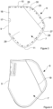
FIGURE 3 is a diagrammatic side view of an air-bag of an example of this disclosure; -
FIGURE 4 is a further diagrammatic side view of the air-bag ofFigure 3 ; -
FIGURE 5 is a further diagrammatic side view of the air-bag ofFigure 3 ; -
FIGURE 6 is a diagrammatic top cross-sectional view along an axis A-A of the air-bag shown inFigure 5 ; -
FIGURE 7 is a diagrammatic side view of the air-bag ofFigure 3 at an intermediate stage of manufacture; -
FIGURE 8 is a diagrammatic top cross-sectional view of the air-bag ofFigure 3 after the air-bag has been inflated; -
FIGURE 9 is a diagrammatic perspective view of the air-bag ofFigure 3 after the air-bag has been inflated; -
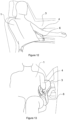
FIGURE 10 is a diagrammatic front view of the air-bag ofFigure 3 after having been inflated within a vehicle; -
FIGURE 11 is a diagrammatic top view of the air-bag ofFigure 3 after having been inflated within a vehicle; -
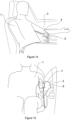
FIGURE 12 is a diagrammatic perspective view of the air-bag ofFigure 3 at an intermediate stage of inflation of the air-bag in a vehicle; -
FIGURE 13 is a diagrammatic front view corresponding toFigure 12 ; -
FIGURE 14 is a diagrammatic perspective view of the air-bag ofFigure 3 at a later stage of inflation of the air-bag in a vehicle; -
FIGURE 15 is a diagrammatic front view corresponding toFigure 14 ; -
FIGURE 16 is a diagrammatic perspective view of the air-bag ofFigure 3 fully inflated in a vehicle; and -
FIGURE 17 is a diagrammatic front view corresponding toFigure 16 ; - Referring now to
Figures 3 to 7 of the accompanying drawings, a side air-bag 6 of an example of this disclosure comprises a first layer offabric 7 and a second layer offabric 8. In this example, the first and second layers offabric fold line 9 so that the layers offabric fabric - The first and second layers of
fabric fabric first end 10 and asecond end 11 of the first layer offabric 7 or between afirst end 12 and asecond end 13 of the second layer offabric 8. In normal use, thefirst ends bag 6 and thesecond ends bag 6 when the air-bag 6 is inflated within a vehicle. - The second layer of
fabric 8 is superimposed on the first layer offabric 7 to form achamber 14 between asection 15 of the first layer offabric 7 and asection 16 of the second layer offabric 8, as shown inFigure 6 of the accompanying drawings. - The air-
bag 6 is provided with agas inlet aperture 17 which, in this example, is positioned at thefold line 9 between the first and second layers offabric bag 6 is provided with amounting aperture 18 in the vicinity of thegas inlet aperture 17 to receive a mounting element to mount a gas generator to the air-bag 6. However, in other examples, themounting aperture 18 is omitted. - The first layer of
fabric 7 is folded with at least one firstelongate pleat 19. In this example, the firstelongate pleat 19 is formed from afirst fold 20 and asecond fold 21, which together form a Z-fold in the first layer offabric 7. In other examples of this disclosure the first layer offabric 7 is folded with at least one first elongate pleat having a fold shape that is different from a Z-fold. - The second layer of
fabric 8 is folded with at least one secondelongate pleat 22. In this example, the secondelongate pleat 22 is formed from afirst fold 23 and asecond fold 24, which together form a Z-fold in the second layer offabric 8. In other examples of this disclosure the second layer offabric 8 is folded with at least one second elongate pleat having a fold shape that is different from a Z-fold. - The first and second
elongate pleats fabric fabric Figures 3 and 4 . Therefore, when the first and secondelongate pleats fabric 7 sits generally flat when superimposed on the second layer offabric 8. - During manufacture of the air-
bag 6, the first and second layers offabric fabric seam 25 that extends at least partly around periphery of the first layer offabric 7 and the second layer offabric 8. Theseam 25 provides a gas tight or substantially gas tight seal that minimises or prevents gas from leaking out from the air-bag 6 upon inflation. - In this example, the first
elongate pleat 19 has afirst end 26 and asecond end 27. Thefirst end 26 of the firstelongate pleat 19 is positioned at thefirst end 10 of the first layer offabric 7. Thesecond end 27 of the firstelongate pleat 19 intersects with anouter edge 28 of the first layer offabric 7 which is remote from thefold line 9. The firstelongate pleat 19 is at an oblique angle relative to the axis of thefold line 9. The firstelongate pleat 19 extends across part of the width of the first layer offabric 7 and divides the first layer offabric 7 into afirst area 29 and asecond area 30, with thefirst area 29 being larger than thesecond area 30. - In this example, the second
elongate pleat 22 has afirst end 31 and asecond end 32. Thefirst end 31 of the secondelongate pleat 22 is positioned at thefirst end 12 of the second layer offabric 8. Thesecond end 32 of the secondelongate pleat 22 intersects with anouter edge 33 of the second layer offabric 8 which is remote from thefold line 9. The secondelongate pleat 22 is at an oblique angle relative to the axis of thefold line 9. The secondelongate pleat 22 extends across part of the width of the second layer offabric 8 and divides the second layer offabric 7 into afirst area 34 and asecond area 35, with thefirst area 34 being larger than thesecond area 35. - In this example, the first layer of
fabric 7 and the second layer offabric 8 are substantially symmetrical or symmetrical in shape about the axis of thefold line 9. In this example, the first and secondelongate pleats fold line 9. - When the first layer of
fabric 7 is folded with the firstelongate pleat 19 and the second layer offabric 8 is folded with the secondelongate pleat 22, thechamber 14 is at a first volume and the air-bag 6 is in a first configuration. The air-bag 6 is in the first configuration when the air-bag 6 is not inflated, for instance when the air-bag 6 is folded and packed within an enclosure. - As will be described in more detail below, the first and second
elongate pleats bag 6 to expand to a greater width than a first portion of the air-bag 6 as the air-bag 6 inflates and transitions between the first configuration and a second configuration. The first portion of the air-bag 6 is formed at least partly by thefirst area 29 of the first layer offabric 7 and thefirst area 34 of the second layer offabric 8. The second portion of the air-bag 6 is formed at least partly by thesecond area 30 of the first layer offabric 7 and thesecond area 35 of the second layer offabric 8. - Referring now to
Figures 8 to 11 of the accompanying drawings, when a gas is introduced into thechamber 14 to inflate the air-bag 6, forces exerted by the gas on the first and second layers offabric section 15 of the first layer offabric 7 apart from thesection 16 of the second layer offabric 8. The forces exerted by the gas on the first and second layers offabric elongate pleats chamber 14 to expand to a second volume which is greater than the first volume to cause the air-bag 6 to transition from the first configuration to the second configuration. - During the transition between the first configuration and the second configuration as the air-
bag 6 inflates, the air-bag 6 expands to at least partly fill a space adjacent to the torso of theoccupant 1, as shown inFigure 10 and 11 . As the air-bag 6 inflates and thepleats bag 6 expands to present anactivation surface 36 which exerts a biassing force on the underside of thearm 4 of theoccupant 1. The biassing force rotates and lifts thearm 4 of theoccupant 1 and the air-bag 6 inflates to fill the space adjacent the torso of theoccupant 1. Once thearm 4 of theoccupant 1 has been lifted, the air-bag is free to contact the torso of theoccupant 1 and provide a cushion between the torso of the occupant and thedoor 3 of the vehicle. In this example, the inflated air-bag 6 is positioned symmetrically beneath thearm 4 of theoccupant 1. The inflated air-bag 6 therefore has improved inboard positioning compared with a conventional side air-bag. - The lifting effect on the
arm 4 of theoccupant 1, due at least partly to the increased width of the air-bag arising from the unfolding pleats 19, 22, minimises the risk of injury to the ribs andshoulder 5 of theoccupant 1. The lifting effect moves thearm 4 of theoccupant 1 out of the way so that thearm 4 is not pressed against the ribs of theoccupant 1 by the inflated air-bag 6 due to forces arising during a crash situation. This also minimises transverse forces exerted on thearm 4 of theoccupant 1 by the inflated air-bag 6 during a crash situation that might strain and injure theshoulder 5 of theoccupant 1. Thearm 4 of theoccupant 1 is instead moved out of the way by the inflating air-bag 6 to enable the air-bag 6 to contact the torso of theoccupant 1. The expansion of the air-bag 6 from the first volume to the second, greater, volume ensures that the air-bag 6 fills the space between the torso of theoccupant 1 and thedoor 3 of the vehicle. This provides improved stabilisation that minimises movement of theoccupant 1 relative to thedoor 3 and helps minimise injury to theoccupant 1 during a crash situation. - In this example, when the air-
bag 6 is fully inflated a first, or top, end of the air-bag 6 has a greater thickness than a second, or bottom, end of the air-bag 6 due to the unfolded pleats 19, 22 being positioned closer to the first, or top, end than the second, or bottom, end of the air-bag 6. The greater thickness of the first, or top, end of the air-bag 6 is appropriate to fill the space between the torso of theoccupant 1 and thedoor 3 of the vehicle, as shown inFigure 10 . The narrower thickness second, or bottom, end of the air-bag 6 is appropriate to fill the smaller space between the leg of theoccupant 1 and thedoor 3, which further stabilises the air-bag in position between theoccupant 1 and thedoor 3. - Referring now to
Figures 12-17 of the accompanying drawings, the effect of the air-bag 6 rotating and lifting thearm 4 of theoccupant 1 as the air-bag 6 inflates is shown at 10.33 ms (Figures 12 and 13 ), 13.00 ms (Figures 14 and 15 ) and 24.67 ms (Figures 16 and 17 ) from the time at which inflation of the air-bag 6 commences. Once the air-bag 6 has been fully inflated, as shown inFigures 16 and 17 , thearm 4 of theoccupant 1 has been rotated by around 90 degrees and the inflated air-bag 6 fills the space between the torso of theoccupant 1 and thedoor 3 of the vehicle. - In the examples described above, there is one first
elongate pleat 19 and one secondelongate pleat 22. However, in other examples of this disclosure, at least one of the first layer offabric 7 and the second layer offabric 8 are provided with a plurality of spaced apart elongate pleats. The number of pleats may be selected to achieve a desired shape of the air-bag upon inflation to provide an appropriate restraint for an occupant of a vehicle. - While the air-bags of the examples described above are nearside air-bags, to be inflated between an occupant of a vehicle and the door or side wall of a vehicle, an air-bag of another example of this disclosure is a farside air-bag to be inflated centrally within a vehicle between two seats. The farside air-bag is of the same configuration and comprises the same elements as the other air-bags described above to ensure that the air-bag lifts the arms of occupants on one or both sides of the air-bag. The farside air-bag contacts the torso of occupants seated on either side of the air-bag to reduce the risk of injury as a result of the occupants striking one another during a crash situation.
- In another example of this disclosure, an air-bag of the type described above comprises an insert or gas diffuser that is coupled to the air-bag adjacent to the
gas inlet opening 17. The insert is configured to be mounted to a gas generator. - In a further example of this disclosure, a side air-bag module comprises an enclosure, a gas generator and an air-bag of one of the examples described above. The gas generator is mounted to an insert that is coupled to the air-bag and the air-bag is folded and received within the enclosure. In some examples, the enclosure is a flexible wrap but in other examples the enclosure is a rigid plastic housing.
- The configuration of the air-bag with at least one first pleat and at least one second pleat reduces the packing space required for the air-bag compared with a conventional air-bag that incorporates additional fabric to enlarge the volume of the inflated air-bag. Providing additional fabric to enlarge an air-bag also typically requires there to be additional seams, which further enlarge the packing size of the air-bag. Removing the need for such additional fabric and additional seams helps minimise the packing size and hence minimise the overall size of the enclosure of the air-bag module. Furthermore, it is easier to manufacture the air-bag of examples of this disclosure with the pleats compared with other air-bags that require additional fabric to be sewn to the main body of the air-bag to enlarge the volume of the air-bag.
- When used in this specification and claims, the terms "comprises" and "comprising" and variations thereof mean that the specified features, steps or integers are included. The terms are not to be interpreted to exclude the presence of other features, steps or components.
- The invention may also broadly consist in the parts, elements, steps, examples and/or features referred to or indicated in the specification individually or collectively in any and all combinations of two or more said parts, elements, steps, examples and/or features. In particular, one or more features in any of the embodiments described herein may be combined with one or more features from any other embodiment(s) described herein.
- Protection may be sought for any features disclosed in any one or more published documents referenced herein in combination with the present disclosure.
- Although certain example embodiments of the invention have been described, the scope of the appended claims is not intended to be limited solely to these embodiments. The claims are to be construed literally, purposively, and/or to encompass equivalents.
- Representative features are set out in the following clauses, which stand alone or may be combined, in any combination, with one or more features disclosed in the text and/or drawings of the specification.
- 1. A side air-bag for a motor vehicle, the air-bag comprising:
- a first layer of fabric; and
- a second layer of fabric, the second layer of fabric being superimposed on the first layer of fabric to form a chamber between a section of the first layer of fabric and a section of the second layer of fabric, the air-bag being configured to transition between a first configuration and a second configuration upon inflation of the air-bag, wherein:
- in the first configuration, the first layer of fabric is folded with at least one first elongate pleat and the second layer of fabric is folded with at least one second elongate pleat and the chamber is at a first volume; and
- in the second configuration, each pleat in the first and second layers of fabric is unfolded to allow the chamber to expand to a second volume, wherein the second volume is greater than the first volume, such that upon inflation of the air-bag within a vehicle, the air-bag transitions between the first configuration and the second configuration to at least partly fill a space adjacent to the torso of an occupant of the vehicle.
- 2. The air-bag of
clause 1, wherein when the air-bag is in the first configuration, the first layer of fabric is folded with a first plurality of elongate pleats that are spaced apart from one another and the second layer of fabric is folded with a second plurality of elongate pleats that are spaced apart from one another. - 3. The air-bag of
clause 1 orclause 2, wherein the first layer of fabric and the second layer of fabric are formed integrally with one another and folded to superimpose the first layer of fabric on the second layer of fabric, and wherein the first layer of fabric is stitched to the second layer of fabric along a seam which extends at least partly around the periphery of the first layer of fabric and the second layer of fabric. - 4. The air-bag of any one of the preceding clauses, wherein the first layer of fabric and the second layer of fabric are symmetrical in shape about an axis; and
the first and second pleats are positioned symmetrically about the axis. - 5. The air-bag any one of the preceding clauses, wherein the chamber comprises a first portion and a second portion, and wherein when the air-bag is inflated and in the second configuration, the second portion has a greater width than the first portion.
- 6. The air-bag of any one of the preceding clauses, wherein the air-bag is configured to be mounted in a vehicle so that, when the air-bag is inflated and in the second configuration, the air-bag is positioned between the torso of the occupant of the vehicle and a side of the vehicle.
- 7. The air-bag of any one of the preceding clauses, wherein the air-bag is configured to be mounted in a vehicle so that, as the air-bag transitions from the first configuration to the second configuration, the inflating air-bag is centrally positioned under an arm of the occupant of the vehicle.
- 8. The air-bag of any one of the preceding clauses, wherein the air-bag is configured to be mounted in a vehicle so that, upon inflation, the inflated air-bag is positioned between two seats of the vehicle.
- 9. The air-bag of any one of the preceding clauses, wherein the air-bag is provided with a gas inlet aperture and an insert coupled to the air-bag adjacent to the gas inlet aperture, the insert being configured to be mounted to a gas generator.
- 10. A side air-bag module comprising:
- an enclosure;
- a gas generator; and
- the air-bag of
clause 9, wherein the gas generator is mounted to the insert and the air-bag is folded and received within the enclosure.
Claims (10)
- A side air-bag for a motor vehicle, the air-bag comprising:a first layer of fabric; anda second layer of fabric, the second layer of fabric being superimposed on the first layer of fabric to form a chamber between a section of the first layer of fabric and a section of the second layer of fabric, the air-bag being configured to transition between a first configuration and a second configuration upon inflation of the air-bag, wherein:in the first configuration, the first layer of fabric is folded with at least one first elongate pleat and the second layer of fabric is folded with at least one second elongate pleat and the chamber is at a first volume; andin the second configuration, each pleat in the first and second layers of fabric is unfolded to allow the chamber to expand to a second volume, wherein the second volume is greater than the first volume, such that upon inflation of the air-bag within a vehicle, the air-bag transitions between the first configuration and the second configuration to at least partly fill a space adjacent to the torso of an occupant of the vehicle.
- The air-bag of claim 1, wherein when the air-bag is in the first configuration, the first layer of fabric is folded with a first plurality of elongate pleats that are spaced apart from one another and the second layer of fabric is folded with a second plurality of elongate pleats that are spaced apart from one another.
- The air-bag of claim 1 or claim 2, wherein the first layer of fabric and the second layer of fabric are formed integrally with one another and folded to superimpose the first layer of fabric on the second layer of fabric, and wherein the first layer of fabric is stitched to the second layer of fabric along a seam which extends at least partly around the periphery of the first layer of fabric and the second layer of fabric.
- The air-bag of any one of the preceding claims, wherein the first layer of fabric and the second layer of fabric are symmetrical in shape about an axis; and
the first and second pleats are positioned symmetrically about the axis. - The air-bag any one of the preceding claims, wherein the chamber comprises a first portion and a second portion, and wherein when the air-bag is inflated and in the second configuration, the second portion has a greater width than the first portion.
- The air-bag of any one of the preceding claims, wherein the air-bag is configured to be mounted in a vehicle so that, when the air-bag is inflated and in the second configuration, the air-bag is positioned between the torso of the occupant of the vehicle and a side of the vehicle.
- The air-bag of any one of the preceding claims, wherein the air-bag is configured to be mounted in a vehicle so that, as the air-bag transitions from the first configuration to the second configuration, the inflating air-bag is centrally positioned under an arm of the occupant of the vehicle.
- The air-bag of any one of the preceding claims, wherein the air-bag is configured to be mounted in a vehicle so that, upon inflation, the inflated air-bag is positioned between two seats of the vehicle.
- The air-bag of any one of the preceding claims, wherein the air-bag is provided with a gas inlet aperture and an insert coupled to the air-bag adjacent to the gas inlet aperture, the insert being configured to be mounted to a gas generator.
- A side air-bag module comprising:an enclosure;a gas generator; andthe air-bag of claim 9, wherein the gas generator is mounted to the insert and the air-bag is folded and received within the enclosure.
Priority Applications (1)
| Application Number | Priority Date | Filing Date | Title |
|---|---|---|---|
| EP23165626.5A EP4438418A1 (en) | 2023-03-30 | 2023-03-30 | Side air-bag |
Applications Claiming Priority (1)
| Application Number | Priority Date | Filing Date | Title |
|---|---|---|---|
| EP23165626.5A EP4438418A1 (en) | 2023-03-30 | 2023-03-30 | Side air-bag |
Publications (1)
| Publication Number | Publication Date |
|---|---|
| EP4438418A1 true EP4438418A1 (en) | 2024-10-02 |
Family
ID=85791937
Family Applications (1)
| Application Number | Title | Priority Date | Filing Date |
|---|---|---|---|
| EP23165626.5A Pending EP4438418A1 (en) | 2023-03-30 | 2023-03-30 | Side air-bag |
Country Status (1)
| Country | Link |
|---|---|
| EP (1) | EP4438418A1 (en) |
Citations (3)
| Publication number | Priority date | Publication date | Assignee | Title |
|---|---|---|---|---|
| US20120013107A1 (en) * | 2010-07-14 | 2012-01-19 | Autoliv Asp, Inc. | Inflatable airbag assemblies with arm-manipulating side airbags |
| US20160368449A1 (en) * | 2013-07-03 | 2016-12-22 | Toyota Jidosha Kabushiki Kaisha | Side airbag device for vehicle |
| US20220355756A1 (en) * | 2019-06-20 | 2022-11-10 | Ashimori Industry Co., Ltd. | Side airbag device |
-
2023
- 2023-03-30 EP EP23165626.5A patent/EP4438418A1/en active Pending
Patent Citations (3)
| Publication number | Priority date | Publication date | Assignee | Title |
|---|---|---|---|---|
| US20120013107A1 (en) * | 2010-07-14 | 2012-01-19 | Autoliv Asp, Inc. | Inflatable airbag assemblies with arm-manipulating side airbags |
| US20160368449A1 (en) * | 2013-07-03 | 2016-12-22 | Toyota Jidosha Kabushiki Kaisha | Side airbag device for vehicle |
| US20220355756A1 (en) * | 2019-06-20 | 2022-11-10 | Ashimori Industry Co., Ltd. | Side airbag device |
Similar Documents
| Publication | Publication Date | Title |
|---|---|---|
| KR102491286B1 (en) | vehicle seat | |
| US8047564B2 (en) | Airbag | |
| US10583799B2 (en) | Overhead inflatable airbag assembly | |
| US8328229B2 (en) | Airbag module | |
| US7770925B2 (en) | Airbag protection flap | |
| CN110293929B (en) | Airbag device | |
| US20170158160A1 (en) | Airbag and airbag apparatus | |
| CN111315619B (en) | Side airbag with accordion-like pelvic folds | |
| CN115362087B (en) | Occupant protection device | |
| WO2005070730A1 (en) | Fabric knee airbac for high internal pressures | |
| WO2019026538A1 (en) | Occupant protection device | |
| WO2015028780A1 (en) | A method of packaging an air-bag | |
| US6918868B2 (en) | Inflatable restraint system for an air bag | |
| JP2025000977A (en) | Side air bag device | |
| US10723307B2 (en) | Airbag module | |
| EP4438418A1 (en) | Side air-bag | |
| US6331015B1 (en) | Air bag fold and method | |
| CN115214518A (en) | Distal balloon device | |
| JPH10175497A (en) | Side airbag device | |
| US12202429B2 (en) | Airbag device | |
| EP2353948B1 (en) | Airbag device | |
| JP7458359B2 (en) | Vehicle side airbag device | |
| EP4360962A1 (en) | Side air-bag | |
| JP7404151B2 (en) | side airbag device | |
| JP4909556B2 (en) | Airbag |
Legal Events
| Date | Code | Title | Description |
|---|---|---|---|
| PUAI | Public reference made under article 153(3) epc to a published international application that has entered the european phase |
Free format text: ORIGINAL CODE: 0009012 |
|
| STAA | Information on the status of an ep patent application or granted ep patent |
Free format text: STATUS: THE APPLICATION HAS BEEN PUBLISHED |
|
| AK | Designated contracting states |
Kind code of ref document: A1 Designated state(s): AL AT BE BG CH CY CZ DE DK EE ES FI FR GB GR HR HU IE IS IT LI LT LU LV MC ME MK MT NL NO PL PT RO RS SE SI SK SM TR |
|
| STAA | Information on the status of an ep patent application or granted ep patent |
Free format text: STATUS: REQUEST FOR EXAMINATION WAS MADE |
|
| 17P | Request for examination filed |
Effective date: 20250328 |
|
| STAA | Information on the status of an ep patent application or granted ep patent |
Free format text: STATUS: EXAMINATION IS IN PROGRESS |
|
| 17Q | First examination report despatched |
Effective date: 20250806 |
|
| GRAP | Despatch of communication of intention to grant a patent |
Free format text: ORIGINAL CODE: EPIDOSNIGR1 |
|
| STAA | Information on the status of an ep patent application or granted ep patent |
Free format text: STATUS: GRANT OF PATENT IS INTENDED |
|
| INTG | Intention to grant announced |
Effective date: 20260327 |