EP4438415A2 - Trailer sensor communications system - Google Patents
Trailer sensor communications system Download PDFInfo
- Publication number
- EP4438415A2 EP4438415A2 EP24185169.0A EP24185169A EP4438415A2 EP 4438415 A2 EP4438415 A2 EP 4438415A2 EP 24185169 A EP24185169 A EP 24185169A EP 4438415 A2 EP4438415 A2 EP 4438415A2
- Authority
- EP
- European Patent Office
- Prior art keywords
- trailer
- processor
- sensor
- filter
- signal
- Prior art date
- Legal status (The legal status is an assumption and is not a legal conclusion. Google has not performed a legal analysis and makes no representation as to the accuracy of the status listed.)
- Granted
Links
Images


Classifications
-
- B—PERFORMING OPERATIONS; TRANSPORTING
- B60—VEHICLES IN GENERAL
- B60R—VEHICLES, VEHICLE FITTINGS, OR VEHICLE PARTS, NOT OTHERWISE PROVIDED FOR
- B60R16/00—Electric or fluid circuits specially adapted for vehicles and not otherwise provided for; Arrangement of elements of electric or fluid circuits specially adapted for vehicles and not otherwise provided for
- B60R16/02—Electric or fluid circuits specially adapted for vehicles and not otherwise provided for; Arrangement of elements of electric or fluid circuits specially adapted for vehicles and not otherwise provided for electric constitutive elements
- B60R16/023—Electric or fluid circuits specially adapted for vehicles and not otherwise provided for; Arrangement of elements of electric or fluid circuits specially adapted for vehicles and not otherwise provided for electric constitutive elements for transmission of signals between vehicle parts or subsystems
-
- B—PERFORMING OPERATIONS; TRANSPORTING
- B60—VEHICLES IN GENERAL
- B60D—VEHICLE CONNECTIONS
- B60D1/00—Traction couplings; Hitches; Draw-gear; Towing devices
- B60D1/58—Auxiliary devices
- B60D1/62—Auxiliary devices involving supply lines, electric circuits or the like
-
- B—PERFORMING OPERATIONS; TRANSPORTING
- B60—VEHICLES IN GENERAL
- B60R—VEHICLES, VEHICLE FITTINGS, OR VEHICLE PARTS, NOT OTHERWISE PROVIDED FOR
- B60R1/00—Optical viewing arrangements; Real-time viewing arrangements for drivers or passengers using optical image capturing systems, e.g. cameras or video systems specially adapted for use in or on vehicles
- B60R1/20—Real-time viewing arrangements for drivers or passengers using optical image capturing systems, e.g. cameras or video systems specially adapted for use in or on vehicles
- B60R1/22—Real-time viewing arrangements for drivers or passengers using optical image capturing systems, e.g. cameras or video systems specially adapted for use in or on vehicles for viewing an area outside the vehicle, e.g. the exterior of the vehicle
-
- H—ELECTRICITY
- H04—ELECTRIC COMMUNICATION TECHNIQUE
- H04N—PICTORIAL COMMUNICATION, e.g. TELEVISION
- H04N23/00—Cameras or camera modules comprising electronic image sensors; Control thereof
- H04N23/80—Camera processing pipelines; Components thereof
- H04N23/81—Camera processing pipelines; Components thereof for suppressing or minimising disturbance in the image signal generation
-
- H—ELECTRICITY
- H04—ELECTRIC COMMUNICATION TECHNIQUE
- H04N—PICTORIAL COMMUNICATION, e.g. TELEVISION
- H04N25/00—Circuitry of solid-state image sensors [SSIS]; Control thereof
- H04N25/60—Noise processing, e.g. detecting, correcting, reducing or removing noise
- H04N25/617—Noise processing, e.g. detecting, correcting, reducing or removing noise for reducing electromagnetic interference, e.g. clocking noise
-
- B—PERFORMING OPERATIONS; TRANSPORTING
- B60—VEHICLES IN GENERAL
- B60R—VEHICLES, VEHICLE FITTINGS, OR VEHICLE PARTS, NOT OTHERWISE PROVIDED FOR
- B60R2300/00—Details of viewing arrangements using cameras and displays, specially adapted for use in a vehicle
- B60R2300/10—Details of viewing arrangements using cameras and displays, specially adapted for use in a vehicle characterised by the type of camera system used
- B60R2300/105—Details of viewing arrangements using cameras and displays, specially adapted for use in a vehicle characterised by the type of camera system used using multiple cameras
-
- B—PERFORMING OPERATIONS; TRANSPORTING
- B60—VEHICLES IN GENERAL
- B60R—VEHICLES, VEHICLE FITTINGS, OR VEHICLE PARTS, NOT OTHERWISE PROVIDED FOR
- B60R2300/00—Details of viewing arrangements using cameras and displays, specially adapted for use in a vehicle
- B60R2300/80—Details of viewing arrangements using cameras and displays, specially adapted for use in a vehicle characterised by the intended use of the viewing arrangement
- B60R2300/802—Details of viewing arrangements using cameras and displays, specially adapted for use in a vehicle characterised by the intended use of the viewing arrangement for monitoring and displaying vehicle exterior blind spot views
Definitions
- This disclosure relates to a sensor communications system for use in a commercial truck, and in particular to a system for providing communications between a sensor such as a trailer-mounted camera, and a camera monitoring system (CMS).
- CMS camera monitoring system
- Mirror replacement systems and camera systems for supplementing mirror views, are utilized in commercial vehicles to enhance the ability of a vehicle operator to see a surrounding environment.
- Camera monitoring systems utilize one or more cameras to provide an enhanced field of view to a vehicle operator.
- the mirror replacement systems cover a larger field of view than a conventional mirror, or include views that are not fully obtainable via a conventional mirror.
- the area behind the trailer is a typical blind spot in a conventional mirror system. It is desirable to provide the operator visibility at the rear of the trailer.
- a vehicle communications system according to the present invention is defined by appended claim 1. Further embodiments of the invention are defined by the appended claims.
- a camera monitoring system for a vehicle including a tractor and trailer includes a trailer that has trailer components that are responsive to at least one control signal and a wiring harness that is in communication with the trailer components and has a connector that is configured to communicate with a tractor.
- the wiring harness is configured to carry the at least one control signal to the trailer components.
- the system further includes a sensor that is provided on the trailer and is configured to generate a sensor signal.
- the system further includes a processor that is interconnected between the sensor and the wiring harness. The processor is configured to transform the sensor signal for transmission over the wiring harness with the at least one control signal using common wires within the wiring harness.
- the system further includes a filter that is interconnected between the processor and at least one of the trailer components and is configured to filter noise from the at least one control signal.
- the trailer components include at least one of a marker light, a brake light, a tail light, a turn signal, and an anti-lock braking system component.
- Each of the trailer components are configured to receive one of the at least one control signal.
- the common wires are provided by unshielded wires.
- the common wires carry the at least one control signal and the sensor signal.
- the common wires include a power wire for one of the trailer components and a ground wire in the wiring harness.
- the at least one control signal and the sensor signal are configured to be transmitted over the common wires.
- a chipset includes the processor and an encoder.
- the encoder is configured to embed the sensor signal into the at least one control signal.
- the system includes additional electrical devices.
- the sensor and the additional electrical devices are connected to multiple inputs of the processor.
- the chipset includes a multiplexer that is configured to combine the multiple inputs to provide the sensor signal as an output of the sensor and electrical devices.
- the processor includes an input.
- the sensor is connected to the input by an ethernet cable.
- the senor is at least one of a camera, a radar, a lidar, an infrared sensor and an ultrasonic sensor.
- the senor is a camera
- the sensor signal is transmitted by the processor over the common wires at a speed of at least 15Mb/s.
- the system includes a camera mirror system for a vehicle that includes a tractor having a vehicle cab, a camera system mounted to the tractor and has fields of view of at least one of Class II and Class IV views, at least one display that is arranged in the vehicle cab and is in communication with the camera system and is configured to display the fields of view, and a controller that is in communication with the camera system and the at least one display.
- the sensor signal is configured to be transmitted to the controller.
- the senor is a camera that is configured to provide the sensor signal to the at least one display.
- the sensor signal is an uncompressed signal with a latency of less than 200 ms.
- the processor is a second processor and the filter is a second filter.
- the tractor has a first processor that is connected to a first filter by unshield twisted pair of wires.
- the first filter is connected to the common wires.
- the first processor is configured to receive the sensor signal via the first filter and transmit the sensor signal to controller.
- the first processor includes a decoder and a demultiplexer that is configured to isolate the sensor signal from the at least one control signal.
- the decoder is provided by at least one of hardware and software.
- At least one of the first and second processors are configured to perform pulse amplitude modulation to reduce noise in the control signal over the common wires.
- one of the trailer components is a light housing that includes at least one of a marker light, a tail light, a brake light and a turn signal.
- the sensor is provided in the light housing.
- one of the trailer components is a light housing and includes at least one of a marker light, a tail light, a brake light and a turn signal.
- An array of IR LEDs are provided in the light housing, and the sensor is a camera.
- the camera is provided in the light housing.
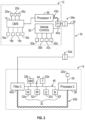
- FIG. 1A and 1B A schematic view of a commercial vehicle 10 is illustrated in Figures 1A and 1B .
- the vehicle 10 includes a vehicle cab or tractor 12 for pulling a trailer 14. Although a commercial truck is contemplated in this disclosure, the disclosed system may also be applied to other types of vehicles.
- the vehicle 10 incorporates a camera monitoring system (CMS) 15 ( Fig. 2 ) that has driver and passenger side camera arms 16a, 16b mounted to the outside of the vehicle cab 12. If desired, the camera arms 16a, 16b may include conventional mirrors integrated with them as well, although the CMS 15 can be used to entirely replace mirrors.
- each side can include multiple camera arms 16, with each arm 16 housing one or more cameras and/or mirrors.
- CMS camera monitoring system
- Each of the camera arms 16a, 16b includes a base that is secured to, for example, the cab 12.
- a pivoting arm is supported by the base and may articulate relative thereto.
- At least one rearward facing camera 20a, 20b is arranged respectively within the camera arms 16a, 16b, e.g., the pivoting arms.
- the exterior cameras 20a, 20b respectively provide an exterior field of view FOV EX1 , FOV EX2 that each include at least one of the Class II and Class IV views ( Fig. 1B ) or similar views, which are legal prescribed views in the commercial trucking industry.
- the Class II view on a given side of the vehicle 10 is a subset of the Class IV view of the same side of the vehicle 10.
- Multiple cameras also may be used in each camera arm 16a, 16b to provide these views, if desired.
- Each arm 16a, 16b may also provide a housing that encloses electronics that are configured to provide various features of the CMS 15.
- First and second video displays 18a, 18b are arranged on each of the driver and passenger sides within the vehicle cab 12 on or near the A-pillars 19a, 19b to display Class II and Class IV views on its respective side of the vehicle 10, which provide rear facing side views along the vehicle 10 that are captured by the exterior cameras 20a, 20b.
- a camera housing 16c and camera 20c may be arranged at or near the front of the vehicle 10 to provide those views ( Fig. 1B ).
- a third display 18c arranged within the cab 12 near the top center of the windshield can be used to display the Class V and Class VI views, which are toward the front of the vehicle 10, to the driver.
- camera housings can be disposed at the sides and rear of the vehicle 10 to provide fields of view including some or all of the Class VIII zones of the vehicle 10.
- the third display 18c can include one or more frames displaying the Class VIII views.
- additional displays can be added near the first, second and third displays 18a, 18b, 18c and provide a display dedicated to providing a Class VIII view.
- the area behind the trailer 14 is a common blind spot for any vehicle, but particularly for commercial trucks. So, it is desirable to provide the operator some awareness of unseen objects at the rear of the trailer using a sensor, such as a camera 20d, as illustrated in Figure 1B .
- a sensor such as a camera 20d
- Challenges to using a camera at the rear of a trailer 14 is the long run of wires that might be used to transmit a video signal to the display in the cab. Dedicated wiring would add significant cost to the system. Additionally, the images must be transmitted with minimal to no latency so objects are displayed in real time.
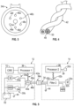
- the trailer 14 includes trailer components 32, such as a marker light 32a, an anti-lock braking system component 32b, a turn signal (right, 32c; left, 32d), a tail light 32e, and a brake light 32f.
- trailer components 32a-32f are responsive to a control signal from one or more vehicle controls 30, e.g., switches 30a-30d.
- the trailer components 32 on the trailer 14 are connected to the tractor 12 by a typical wiring harness 34.
- a standard 7-pin jumper cable 35 interconnects the tractor 12 and trailer 14 at connectors 34a, 34b, which are of a typical configuration (e.g., Fig. 3 ).
- the disclosed system can be used with the existing ubiquitous trailer wiring harnesses and electrical connectors in the industry.
- ground wires 44 there are various ground wires 44 in the system, only some of which are shown.
- Wires within a common wiring harness 34 are unshielded copper wire, typically multiple copper wire strands covered in a polymer insulation.
- a common ground 44 is provided, and control signals for the marker light 32a, the anti-lock braking system component 32b, the turn signal (right, 32c; left, 32d), the tail light 32e, and the brake light 32f are respectively sent over power wires 46a-46f.
- the camera 20d has an image capture unit that generates a sensor signal that must be sent at a high transmission rate.
- the disclosed system accomplishes this transmission without the need for dedicated wiring running from the rear of the trailer 14 all the way to the tractor 12, which greatly simplifies installation and reduces cost. Desired sensor signal transmission is achieved over the very same power wires on the trailer 14 used to transmit control signals to the trailer components 32.
- the tractor 12 has a first processor 36 that transmits the received sensor signal to the CMS 15 for display to the operator.
- a second processor 38 is arranged on the trailer 14 and interconnected between the sensor 20d and the wiring harness 34.
- the second processor 38 is configured to transform the sensor signal for transmission over the wiring harness 34 with the control signal using wires that are common with the wiring harness wires used to carry control signals to the trailer components 32.
- several of the existing wires e.g., a power wire and a ground wire, have a dual purpose: carrying a control signal and the sensor signal.
- An example chipset that may be used is available as VA6000 from Valens Semiconductor Ltd., although it should be understood that other processors can be used and fall within the scope of the disclosed system.
- Another example chipset is the DCB1M available from Yamar Electronics Ltd.
- first and second filters 40a, 40b are used at the signal tap locations, for example, respectively in the tractor and trailer wiring harness to filter out noise prior to transmission to the processors.
- Each of the filters 40a, 40b are connected to its respective first and second processor 36, 38 by an unshielded twisted pair of wires 42a, 42b (shown as "42" in Fig. 4 ).
- the twisted wire pairs are unshielded copper wire, typically multiple copper wire strands 48 covered in a polymer insulation 50, as shown in Figure 4 .
- the second processor 38 includes an input, and the camera 20d is connected to the input by a high-speed transmission cable 39, such as an ethernet cable.
- the second processor 38 may be provided by a chipset that includes a processor and an encoder, which is configured to embed the sensor signal into the control signal for transmission along the power wire(s) to the first processor 36. Additional electrical devices may be connected to multiple inputs, if provided on the processor. The other inputs may accommodate, for example, IRLEDs associated with the camera 20d.
- the chipset may include a multiplexer configured to combine the inputs to provide the sensor signal as an output of the sensor along with outputs from the electrical devices.
- the first processor 36 includes a decoder and a demultiplexer, which can be provided on the same chipset or separately, that are configured to isolate the sensor signal from the control signal.
- the decoder is provided by at least one of hardware and software.
- At least one of the first and second processors 36, 38 are configured to perform pulse amplitude modulation to reduce noise in the control signal over the common power wires.
- the second processor 38 is configured to receive the sensor signal from the camera 20d and transmit the sensor signal to CMS controller 15.
- the second processor 38 embeds the sensor signal with the control signal on the power wires for the trailer components 32, such as over ABS and marker light power wires 46a, 48b.
- This combined sensor/control signal is transmitted along the trailer wiring harness 34 to the second filter 40b to filter any noise from the trailer components.
- the second filter 40b is placed at a location and on power lines where the noise can be more easily filtered and to reduce the length of wires between the second filter 40 and the second processor 38.
- the combined sensor/control signal is transmitted to the tractor 14 to a point "downstream" from vehicle component switches 54a, 54b to the first processor 36, where the sensor signal is decoded and transmitted to the CMS controller 15 for display.
- Each or both of the sensor signal and/or control signal may also be transmitted bi-directionally, if desired.
- the vehicle component switches 54a, 54b e.g., trailer marker light switch and brake pedal
- a power source 52 such as the vehicle's battery to selectively supply voltage, i.e., the control signal, to the trailer component.
- the first filter 40a must be located on the same pair of power transmission lines as the second filter 40b. The first filter 40 filters noise from the power wires to isolate the image signal sent from the second processor 38.
- the senor is described above as a camera 20d, it should be understood that other sensors may also be used in addition to or instead of a camera, such as a radar sensor, a lidar sensor, an infrared sensor and an ultrasonic sensor.
- a camera it is desirable to transmit the sensor signal between the first and second processors 36, 38 and on to the CMS 15 over the common wires at a speed of at least 15Mb/s. Compressing the sensor signal could result in undesired latency.
- the disclosed system is capable of achieving the desired transmission rate, without compression, with the minimal latency needed in a CMS system, i.e., less than 200 ms.
- a light housing 60 (e.g., a marker light, a tail light, a brake light and a turn signal) has the sensor 64, such as a camera 20d, provided in the housing 60.
- the lights 62 may be provided by LEDs 62 or incandescent bulbs for emitting visible light.
- An array of IR LEDs 66 powered by wires 146e may also be provided in the housing 66 if night vision is desired for the camera.
- the light housing 60 is sealed by a lens 68, which may cover the sensor as well. If desired, a separate lens 70 may be used over the sensor 64 and integrated with the lens 68, depending upon the application.
- the light housing 160 in Figure 6A uses a lens 168 and with no IR LEDs.
- the controller in the CMS can be used to implement the various functionality disclosed in this application.
- the controller may include one or more discrete units.
- the first processor 36 can be incorporated into the CMS controller or separate, but the second processor 38 will be separate from the first processor 36 as the second processor resides on the trailer 14.
- a portion of the controller may be provided in the vehicle, while another portion of the controller may be located elsewhere.
- such a computing device can include a processor, memory, and one or more input and/or output (I/O) device interface(s) that are communicatively coupled via a local interface.
- the local interface can include, for example but not limited to, one or more buses and/or other wired or wireless connections.
- the local interface may have additional elements, which are omitted for simplicity, such as controllers, buffers (caches), drivers, repeaters, and receivers to enable communications. Further, the local interface may include address, control, and/or data connections to enable appropriate communications among the aforementioned components.
- the controller may be a hardware device for executing software, particularly software stored in memory.
- the controller can be a custom made or commercially available processor, a central processing unit (CPU), an auxiliary processor among several processors associated with the controller, a semiconductor-based microprocessor (in the form of a microchip or chip set) or generally any device for executing software instructions.
- the memory can include any one or combination of volatile memory elements (e.g., random access memory (RAM, such as DRAM, SRAM, SDRAM, VRAM, etc.)) and/or nonvolatile memory elements (e.g., ROM, hard drive, tape, CD-ROM, etc.). Moreover, the memory may incorporate electronic, magnetic, optical, and/or other types of storage media. The memory can also have a distributed architecture, where various components are situated remotely from one another, but can be accessed by the processor.
- volatile memory elements e.g., random access memory (RAM, such as DRAM, SRAM, SDRAM, VRAM, etc.
- nonvolatile memory elements e.g., ROM, hard drive, tape, CD-ROM, etc.
- the memory can also have a distributed architecture, where various components are situated remotely from one another, but can be accessed by the processor.
- the software in the memory may include one or more separate programs, each of which includes an ordered listing of executable instructions for implementing logical functions.
- a system component embodied as software may also be construed as a source program, executable program (object code), script, or any other entity comprising a set of instructions to be performed.
- the program is translated via a compiler, assembler, interpreter, or the like, which may or may not be included within the memory.
- the disclosed input and output devices that may be coupled to system I/O interface(s) may include input devices, for example but not limited to, a keyboard, mouse, scanner, microphone, camera, mobile device, proximity device, etc. Further, the output devices, for example but not limited to, a display, macroclimate device, microclimate device, etc. Finally, the input and output devices may further include devices that communicate both as inputs and outputs, for instance but not limited to, a modulator/demodulator (modem; for accessing another device, system, or network), a radio frequency (RF) or other transceiver, a telephonic interface, a bridge, a router, etc.
- modem for accessing another device, system, or network
- RF radio frequency
- the processor can be configured to execute software stored within the memory, to communicate data to and from the memory, and to generally control operations of the computing device pursuant to the software.
- Software in memory in whole or in part, is read by the processor, perhaps buffered within the processor, and then executed.
Landscapes
- Engineering & Computer Science (AREA)
- Multimedia (AREA)
- Mechanical Engineering (AREA)
- Signal Processing (AREA)
- Physics & Mathematics (AREA)
- Electromagnetism (AREA)
- Transportation (AREA)
- Closed-Circuit Television Systems (AREA)
- Arrangements For Transmission Of Measured Signals (AREA)
- Fittings On The Vehicle Exterior For Carrying Loads, And Devices For Holding Or Mounting Articles (AREA)
Abstract
Description
- This disclosure relates to a sensor communications system for use in a commercial truck, and in particular to a system for providing communications between a sensor such as a trailer-mounted camera, and a camera monitoring system (CMS).
- Mirror replacement systems, and camera systems for supplementing mirror views, are utilized in commercial vehicles to enhance the ability of a vehicle operator to see a surrounding environment. Camera monitoring systems (CMS) utilize one or more cameras to provide an enhanced field of view to a vehicle operator. In some examples, the mirror replacement systems cover a larger field of view than a conventional mirror, or include views that are not fully obtainable via a conventional mirror.
- The area behind the trailer is a typical blind spot in a conventional mirror system. It is desirable to provide the operator visibility at the rear of the trailer.
- A vehicle communications system according to the present invention is defined by appended
claim 1. Further embodiments of the invention are defined by the appended claims. - In one example, a camera monitoring system for a vehicle including a tractor and trailer includes a trailer that has trailer components that are responsive to at least one control signal and a wiring harness that is in communication with the trailer components and has a connector that is configured to communicate with a tractor. The wiring harness is configured to carry the at least one control signal to the trailer components. The system further includes a sensor that is provided on the trailer and is configured to generate a sensor signal. The system further includes a processor that is interconnected between the sensor and the wiring harness. The processor is configured to transform the sensor signal for transmission over the wiring harness with the at least one control signal using common wires within the wiring harness. The system further includes a filter that is interconnected between the processor and at least one of the trailer components and is configured to filter noise from the at least one control signal.
- In a further example, the trailer components include at least one of a marker light, a brake light, a tail light, a turn signal, and an anti-lock braking system component. Each of the trailer components are configured to receive one of the at least one control signal.
- In a further example, the noise is generated by the trailer components.
- In a example, the common wires are provided by unshielded wires. The common wires carry the at least one control signal and the sensor signal.
- In a example, the common wires include a power wire for one of the trailer components and a ground wire in the wiring harness. The at least one control signal and the sensor signal are configured to be transmitted over the common wires.
- In a further example, a chipset includes the processor and an encoder. The encoder is configured to embed the sensor signal into the at least one control signal.
- In a further example, the system includes additional electrical devices. The sensor and the additional electrical devices are connected to multiple inputs of the processor. The chipset includes a multiplexer that is configured to combine the multiple inputs to provide the sensor signal as an output of the sensor and electrical devices.
- In a further example, the processor includes an input. The sensor is connected to the input by an ethernet cable.
- In a further example, the sensor is at least one of a camera, a radar, a lidar, an infrared sensor and an ultrasonic sensor.
- In a further example, the sensor is a camera, and the sensor signal is transmitted by the processor over the common wires at a speed of at least 15Mb/s.
- In a further example, the system includes a camera mirror system for a vehicle that includes a tractor having a vehicle cab, a camera system mounted to the tractor and has fields of view of at least one of Class II and Class IV views, at least one display that is arranged in the vehicle cab and is in communication with the camera system and is configured to display the fields of view, and a controller that is in communication with the camera system and the at least one display. The sensor signal is configured to be transmitted to the controller.
- In a further example, the sensor is a camera that is configured to provide the sensor signal to the at least one display.
- In a further example, the sensor signal is an uncompressed signal with a latency of less than 200 ms.
- In a further example, the processor is a second processor and the filter is a second filter. The tractor has a first processor that is connected to a first filter by unshield twisted pair of wires. The first filter is connected to the common wires. The first processor is configured to receive the sensor signal via the first filter and transmit the sensor signal to controller.
- In a example, the first processor includes a decoder and a demultiplexer that is configured to isolate the sensor signal from the at least one control signal.
- In a example, the decoder is provided by at least one of hardware and software.
- In a further example, at least one of the first and second processors are configured to perform pulse amplitude modulation to reduce noise in the control signal over the common wires.
- In a example, one of the trailer components is a light housing that includes at least one of a marker light, a tail light, a brake light and a turn signal. The sensor is provided in the light housing.
- In a example, one of the trailer components is a light housing and includes at least one of a marker light, a tail light, a brake light and a turn signal. An array of IR LEDs are provided in the light housing, and the sensor is a camera.
- In a further example, the camera is provided in the light housing.
- The disclosure can be further understood by reference to the following detailed description when considered in connection with the accompanying drawings wherein:
-
Figure 1A is a schematic front view of a commercial truck with a camera monitoring system (CMS) used to provide at least Class II and Class IV views. -
Figure 1B is a schematic top elevational view of a commercial truck with a camera mirror system providing Class II, Class IV, Class V and Class VI views. -
Figure 2 is a schematic of a trailer camera communications system. -
Figure 3 is an end view of a trailer wiring harness connector. -
Figure 4 depicts an unshielded twisted wire pair used to connect a processor and a filter in a trailer wiring harness. -
Figure 5 is a schematic of an example implementation of the trailer camera communications system. -
Figures 6A and 6B are examples of a sensor integrated into trailer light housings. - The embodiments, examples and alternatives of the preceding paragraphs, the claims, or the following description and drawings, including any of their various aspects or respective individual features, may be taken independently or in any combination. Features described in connection with one embodiment are applicable to all embodiments, unless such features are incompatible.
- A schematic view of a
commercial vehicle 10 is illustrated inFigures 1A and1B . Thevehicle 10 includes a vehicle cab ortractor 12 for pulling atrailer 14. Although a commercial truck is contemplated in this disclosure, the disclosed system may also be applied to other types of vehicles. Thevehicle 10 incorporates a camera monitoring system (CMS) 15 (Fig. 2 ) that has driver and passengerside camera arms vehicle cab 12. If desired, thecamera arms CMS 15 can be used to entirely replace mirrors. In additional examples, each side can include multiple camera arms 16, with each arm 16 housing one or more cameras and/or mirrors. - Each of the
camera arms cab 12. A pivoting arm is supported by the base and may articulate relative thereto. At least one rearward facingcamera camera arms exterior cameras Fig. 1B ) or similar views, which are legal prescribed views in the commercial trucking industry. The Class II view on a given side of thevehicle 10 is a subset of the Class IV view of the same side of thevehicle 10. Multiple cameras also may be used in eachcamera arm arm CMS 15. - First and
second video displays vehicle cab 12 on or near the A-pillars 19a, 19b to display Class II and Class IV views on its respective side of thevehicle 10, which provide rear facing side views along thevehicle 10 that are captured by theexterior cameras - If video of Class V and Class VI views are also desired, a
camera housing 16c andcamera 20c may be arranged at or near the front of thevehicle 10 to provide those views (Fig. 1B ). Athird display 18c arranged within thecab 12 near the top center of the windshield can be used to display the Class V and Class VI views, which are toward the front of thevehicle 10, to the driver. - If video of Class VIII views is desired, camera housings can be disposed at the sides and rear of the
vehicle 10 to provide fields of view including some or all of the Class VIII zones of thevehicle 10. In such examples, thethird display 18c can include one or more frames displaying the Class VIII views. Alternatively, additional displays can be added near the first, second andthird displays - It should be understood that more or fewer displays can be used than schematically illustrated, and the displayed images from more than one camera may be combined on a single display, or an image from a particular field of view may be provided on a separate, discrete display from another image.
- The area behind the
trailer 14 is a common blind spot for any vehicle, but particularly for commercial trucks. So, it is desirable to provide the operator some awareness of unseen objects at the rear of the trailer using a sensor, such as acamera 20d, as illustrated inFigure 1B . Challenges to using a camera at the rear of atrailer 14 is the long run of wires that might be used to transmit a video signal to the display in the cab. Dedicated wiring would add significant cost to the system. Additionally, the images must be transmitted with minimal to no latency so objects are displayed in real time. - Referring to
Figure 2 , thetrailer 14 includestrailer components 32, such as amarker light 32a, an anti-lockbraking system component 32b, a turn signal (right, 32c; left, 32d), atail light 32e, and abrake light 32f. Each of thetrailer components 32a-32f (collectively, trailer components 32) are responsive to a control signal from one or more vehicle controls 30, e.g., switches 30a-30d. Thetrailer components 32 on thetrailer 14 are connected to thetractor 12 by atypical wiring harness 34. As an example, a standard 7-pin jumper cable 35 interconnects thetractor 12 andtrailer 14 atconnectors Fig. 3 ). As a result, the disclosed system can be used with the existing ubiquitous trailer wiring harnesses and electrical connectors in the industry. - There are
various ground wires 44 in the system, only some of which are shown. Wires within acommon wiring harness 34 are unshielded copper wire, typically multiple copper wire strands covered in a polymer insulation. For a standard 7-pin arrangement, shown inFigure 3 , acommon ground 44 is provided, and control signals for themarker light 32a, the anti-lockbraking system component 32b, the turn signal (right, 32c; left, 32d), thetail light 32e, and thebrake light 32f are respectively sent overpower wires 46a-46f. - The
camera 20d has an image capture unit that generates a sensor signal that must be sent at a high transmission rate. The disclosed system accomplishes this transmission without the need for dedicated wiring running from the rear of thetrailer 14 all the way to thetractor 12, which greatly simplifies installation and reduces cost. Desired sensor signal transmission is achieved over the very same power wires on thetrailer 14 used to transmit control signals to thetrailer components 32. - The
tractor 12 has afirst processor 36 that transmits the received sensor signal to theCMS 15 for display to the operator. Asecond processor 38 is arranged on thetrailer 14 and interconnected between thesensor 20d and thewiring harness 34. Thesecond processor 38 is configured to transform the sensor signal for transmission over thewiring harness 34 with the control signal using wires that are common with the wiring harness wires used to carry control signals to thetrailer components 32. Said another way, several of the existing wires, e.g., a power wire and a ground wire, have a dual purpose: carrying a control signal and the sensor signal. An example chipset that may be used is available as VA6000 from Valens Semiconductor Ltd., although it should be understood that other processors can be used and fall within the scope of the disclosed system. Another example chipset is the DCB1M available from Yamar Electronics Ltd. - Noise is generated by the
trailer components 32, such that a usable image signal may not be provided to the first andsecond processors second filters filters second processor wires Fig. 4 ). The twisted wire pairs are unshielded copper wire, typically multiplecopper wire strands 48 covered in apolymer insulation 50, as shown inFigure 4 . - The
second processor 38 includes an input, and thecamera 20d is connected to the input by a high-speed transmission cable 39, such as an ethernet cable. Thesecond processor 38 may be provided by a chipset that includes a processor and an encoder, which is configured to embed the sensor signal into the control signal for transmission along the power wire(s) to thefirst processor 36. Additional electrical devices may be connected to multiple inputs, if provided on the processor. The other inputs may accommodate, for example, IRLEDs associated with thecamera 20d. The chipset may include a multiplexer configured to combine the inputs to provide the sensor signal as an output of the sensor along with outputs from the electrical devices. - The
first processor 36 includes a decoder and a demultiplexer, which can be provided on the same chipset or separately, that are configured to isolate the sensor signal from the control signal. The decoder is provided by at least one of hardware and software. - At least one of the first and
second processors - In operation, with reference to
Figure 5 , thesecond processor 38 is configured to receive the sensor signal from thecamera 20d and transmit the sensor signal toCMS controller 15. Thesecond processor 38 embeds the sensor signal with the control signal on the power wires for thetrailer components 32, such as over ABS and markerlight power wires 46a, 48b. This combined sensor/control signal is transmitted along thetrailer wiring harness 34 to thesecond filter 40b to filter any noise from the trailer components. Ideally, thesecond filter 40b is placed at a location and on power lines where the noise can be more easily filtered and to reduce the length of wires between the second filter 40 and thesecond processor 38. - The combined sensor/control signal is transmitted to the
tractor 14 to a point "downstream" fromvehicle component switches first processor 36, where the sensor signal is decoded and transmitted to theCMS controller 15 for display. Each or both of the sensor signal and/or control signal may also be transmitted bi-directionally, if desired. Thevehicle component switches power source 52, such as the vehicle's battery to selectively supply voltage, i.e., the control signal, to the trailer component. Thefirst filter 40a must be located on the same pair of power transmission lines as thesecond filter 40b. The first filter 40 filters noise from the power wires to isolate the image signal sent from thesecond processor 38. - Although the sensor is described above as a
camera 20d, it should be understood that other sensors may also be used in addition to or instead of a camera, such as a radar sensor, a lidar sensor, an infrared sensor and an ultrasonic sensor. In the case of a camera, it is desirable to transmit the sensor signal between the first andsecond processors CMS 15 over the common wires at a speed of at least 15Mb/s. Compressing the sensor signal could result in undesired latency. The disclosed system is capable of achieving the desired transmission rate, without compression, with the minimal latency needed in a CMS system, i.e., less than 200 ms. - To provide further efficiencies, the sensor can be integrated into a light housing on the
trailer 14, as shown inFigures 6A and 6B . Referring toFigure 6B , a light housing 60 (e.g., a marker light, a tail light, a brake light and a turn signal) has thesensor 64, such as acamera 20d, provided in thehousing 60. Thelights 62 may be provided byLEDs 62 or incandescent bulbs for emitting visible light. An array ofIR LEDs 66 powered bywires 146e may also be provided in thehousing 66 if night vision is desired for the camera. Thelight housing 60 is sealed by alens 68, which may cover the sensor as well. If desired, aseparate lens 70 may be used over thesensor 64 and integrated with thelens 68, depending upon the application. Thelight housing 160 inFigure 6A uses alens 168 and with no IR LEDs. - Incorporating IR LEDs, and optionally a camera, into a ubiquitous taillight assembly would obviate the need for any specialized mounting brackets or hardware when adding night vision or another view at the rear of the trailer.
- The controller in the CMS can be used to implement the various functionality disclosed in this application. The controller may include one or more discrete units. The
first processor 36 can be incorporated into the CMS controller or separate, but thesecond processor 38 will be separate from thefirst processor 36 as the second processor resides on thetrailer 14. Moreover, a portion of the controller may be provided in the vehicle, while another portion of the controller may be located elsewhere. In terms of hardware architecture, such a computing device can include a processor, memory, and one or more input and/or output (I/O) device interface(s) that are communicatively coupled via a local interface. The local interface can include, for example but not limited to, one or more buses and/or other wired or wireless connections. The local interface may have additional elements, which are omitted for simplicity, such as controllers, buffers (caches), drivers, repeaters, and receivers to enable communications. Further, the local interface may include address, control, and/or data connections to enable appropriate communications among the aforementioned components. - The controller may be a hardware device for executing software, particularly software stored in memory. The controller can be a custom made or commercially available processor, a central processing unit (CPU), an auxiliary processor among several processors associated with the controller, a semiconductor-based microprocessor (in the form of a microchip or chip set) or generally any device for executing software instructions.
- The memory can include any one or combination of volatile memory elements (e.g., random access memory (RAM, such as DRAM, SRAM, SDRAM, VRAM, etc.)) and/or nonvolatile memory elements (e.g., ROM, hard drive, tape, CD-ROM, etc.). Moreover, the memory may incorporate electronic, magnetic, optical, and/or other types of storage media. The memory can also have a distributed architecture, where various components are situated remotely from one another, but can be accessed by the processor.
- The software in the memory may include one or more separate programs, each of which includes an ordered listing of executable instructions for implementing logical functions. A system component embodied as software may also be construed as a source program, executable program (object code), script, or any other entity comprising a set of instructions to be performed. When constructed as a source program, the program is translated via a compiler, assembler, interpreter, or the like, which may or may not be included within the memory.
- The disclosed input and output devices that may be coupled to system I/O interface(s) may include input devices, for example but not limited to, a keyboard, mouse, scanner, microphone, camera, mobile device, proximity device, etc. Further, the output devices, for example but not limited to, a display, macroclimate device, microclimate device, etc. Finally, the input and output devices may further include devices that communicate both as inputs and outputs, for instance but not limited to, a modulator/demodulator (modem; for accessing another device, system, or network), a radio frequency (RF) or other transceiver, a telephonic interface, a bridge, a router, etc.
- When the controller is in operation, the processor can be configured to execute software stored within the memory, to communicate data to and from the memory, and to generally control operations of the computing device pursuant to the software. Software in memory, in whole or in part, is read by the processor, perhaps buffered within the processor, and then executed.
- It should also be understood that although a particular component arrangement is disclosed in the illustrated embodiment, other arrangements will benefit herefrom. Although particular step sequences are shown, described, and claimed, it should be understood that steps may be performed in any order, separated or combined unless otherwise indicated and will still benefit from the present invention.
- Although the different examples have specific components shown in the illustrations, embodiments of this invention are not limited to those particular combinations. It is possible to use some of the components or features from one of the examples in combination with features or components from another one of the examples.
- Although an example embodiment has been disclosed, a worker of ordinary skill in this art would recognize that certain modifications would come within the scope of the claims. For that reason, the following claims should be studied to determine their true scope and content.
Claims (13)
- A vehicle communications system (15) including a tractor (12) and a trailer (14), comprising:a first processor (36) connected to a first filter (40a) and configured to be provided on a tractor (12), the first filter (40a) is configured to receive at least one control signal from at least one vehicle control (30) and communicate the at least one control signal to at least one trailer component (32);a second processor (38) connected to a second filter (40b) and configured to be provided on a trailer (14), the second filter (40b) interconnected between the second processor (38) and the at least one trailer component (32);a sensor (20d) connected to the second processor (38) and configured to be provided on the trailer (14) and to generate a sensor signal; anda wiring harness (34) configured to be in communication with the first filter (40a) and the at least one vehicle control (30) on the tractor (12) and with the second filter (40b) and the at least one trailer component (32) on the trailer (14), the wiring harness (34) having common wires that are configured to carry the at least one control signal from the first filter (40a) to the at least one trailer component (32) via the second filter (40b), and the common wires configured to carry the sensor signal transformed by the second processor (38) from the second filter (40b) to the first processor (36) via the first filter (40a).
- The system (15) of claim 1, wherein the at least one vehicle control (30) includes multiple switches (30a, 30b, 30c, 30d) configured to be connected to multiple trailer components (32a, 32b, 32c, 32d, 32e, 32f) of the at least one trailer component (32), and the at least one trailer components (32) include at least one of a marker light (32a), a brake light (32f), a tail light (32e), a turn signal (32c, 32d), and an anti-lock braking system (32b) component, each of the at least one trailer components (32) configured to receive one of the at least one control signal.
- The system (15) of claims 1 or 2, wherein the wiring harness (34) includes a 7-pin cable interconnecting the tractor (12) and the trailer (14), wherein the at least one control signal and the sensor signal are configured to be communicated over the 7-pin cable, the 7-pin cable including the common wires which correspond to a pair of power transmission lines connected to one of the at least one trailer components (32).
- The system (15) of any preceding claim, wherein the sensor (20d) is at least one of a camera, a radar, a lidar, an infrared sensor and an ultrasonic sensor.
- The system (15) of claim 4, wherein the sensor (20d) is a camera, and the sensor signal is a video signal transmitted by the second processor (38) over the common wires at a speed of at least 15Mb/s.
- The system (15) of any preceding claim, wherein the second processor (38) includes a chipset including at least one processor and an encoder, the encoder configured to embed the sensor signal into the at least one control signals.
- The system (15) of claim 6, comprising additional electrical devices, the sensor and the additional electrical devices connected to multiple inputs of the second processor (38), the chipset includes a multiplexer configured to combine the multiple inputs to provide the sensor signal as an output of the sensor (20d) and electrical devices.
- The system (15) of any preceding claim, wherein the first processor (36) includes a decoder and a demultiplexer configured to isolate the sensor signal from the at least one control signal.
- The system (15) of claim 8, wherein the decoder is provided by at least one of hardware and software.
- The system (15) of any preceding claim, wherein at least one of the first and second processors (36, 38) are configured to perform pulse amplitude modulation to reduce noise in the control signal over the common wires.
- The system (15) of any preceding claim, wherein the common wires include a twisted pair of wires (42).
- The system of claim 11, wherein the twisted pair of wires (42) are unshielded wires.
- The system (15) of any preceding claim, comprising a camera mirror system for a vehicle including:a camera system (15) having multiple rear-facing fields of view (FOVEX1, FOVEX2);multiple displays (18) in communication with the camera system (15) and configured to display the multiple rear-facing fields of view (FOVEX1, FOVEX2); anda controller in communication with the camera system (15) and the multiple displays (18), the sensor signal configured to be transmitted to the controller, wherein the sensor is a camera (20d) configured to provide the sensor signal to at least one of the multiple displays (18), wherein the sensor signal is a signal with a latency of less than 200 ms.
Applications Claiming Priority (3)
| Application Number | Priority Date | Filing Date | Title |
|---|---|---|---|
| US202163213938P | 2021-06-23 | 2021-06-23 | |
| PCT/US2022/034710 WO2022271940A1 (en) | 2021-06-23 | 2022-06-23 | Trailer camera communications system |
| EP22744061.7A EP4359264B1 (en) | 2021-06-23 | 2022-06-23 | Trailer camera communications system |
Related Parent Applications (2)
| Application Number | Title | Priority Date | Filing Date |
|---|---|---|---|
| EP22744061.7A Division EP4359264B1 (en) | 2021-06-23 | 2022-06-23 | Trailer camera communications system |
| EP22744061.7A Division-Into EP4359264B1 (en) | 2021-06-23 | 2022-06-23 | Trailer camera communications system |
Publications (3)
| Publication Number | Publication Date |
|---|---|
| EP4438415A2 true EP4438415A2 (en) | 2024-10-02 |
| EP4438415A3 EP4438415A3 (en) | 2024-10-30 |
| EP4438415B1 EP4438415B1 (en) | 2026-01-14 |
Family
ID=82608522
Family Applications (2)
| Application Number | Title | Priority Date | Filing Date |
|---|---|---|---|
| EP24185169.0A Active EP4438415B1 (en) | 2021-06-23 | 2022-06-23 | Trailer sensor communications system |
| EP22744061.7A Active EP4359264B1 (en) | 2021-06-23 | 2022-06-23 | Trailer camera communications system |
Family Applications After (1)
| Application Number | Title | Priority Date | Filing Date |
|---|---|---|---|
| EP22744061.7A Active EP4359264B1 (en) | 2021-06-23 | 2022-06-23 | Trailer camera communications system |
Country Status (6)
| Country | Link |
|---|---|
| US (2) | US11993113B2 (en) |
| EP (2) | EP4438415B1 (en) |
| JP (1) | JP2024524225A (en) |
| CN (1) | CN117545665A (en) |
| BR (1) | BR112023026120A2 (en) |
| WO (1) | WO2022271940A1 (en) |
Families Citing this family (4)
| Publication number | Priority date | Publication date | Assignee | Title |
|---|---|---|---|---|
| WO2022271940A1 (en) * | 2021-06-23 | 2022-12-29 | Stoneridge Electronics Ab | Trailer camera communications system |
| WO2024184424A1 (en) * | 2023-03-08 | 2024-09-12 | Stoneridge Electronics Ab | Camera monitor system with trailer reverse park assist having graphical overlay |
| WO2025133231A1 (en) * | 2023-12-21 | 2025-06-26 | Stoneridge Electronics Ab | Trailer communication system |
| WO2025181385A1 (en) * | 2024-03-01 | 2025-09-04 | Stoneridge Electronics Ab | Camera monitor system with real-time trailer status hmi |
Family Cites Families (15)
| Publication number | Priority date | Publication date | Assignee | Title |
|---|---|---|---|---|
| US20210309194A1 (en) * | 2012-10-30 | 2021-10-07 | Curt Manufacturing, Llc | Trailer management system |
| US9499109B2 (en) * | 2015-01-27 | 2016-11-22 | Peterson Manufacturing Company | Trailer communication system |
| US20170240125A1 (en) * | 2016-02-19 | 2017-08-24 | GM Global Technology Operations LLC | System for communicating between vehicle and trailer and method of using the same |
| US10427266B2 (en) * | 2016-07-28 | 2019-10-01 | Snap-On Incorporated | Method, system, and apparatus for providing notification pertaining to actionable condition of electrical shop tool |
| US20180372875A1 (en) | 2017-06-27 | 2018-12-27 | Uber Technologies, Inc. | Sensor configuration for an autonomous semi-truck |
| US11364885B2 (en) * | 2018-01-18 | 2022-06-21 | Vieletech Inc. | Smart trailer controller |
| US10854023B1 (en) * | 2018-02-26 | 2020-12-01 | Lytx, Inc. | Tractor-trailer data link for a semi-truck |
| WO2020112528A1 (en) * | 2018-11-29 | 2020-06-04 | Grote Industries, Inc. | Adapter for selecting lamp function in a truck trailer |
| US10926594B2 (en) * | 2019-04-29 | 2021-02-23 | Grote Industries, Inc. | Cable system for a truck trailer |
| US11225194B2 (en) * | 2019-05-16 | 2022-01-18 | Stoneridge Electronics Ab | Camera mirror system vehicle integration |
| US20210162922A1 (en) * | 2019-12-02 | 2021-06-03 | Ficosa North America Corporation | Vehicle imaging system |
| US11685394B2 (en) * | 2020-07-29 | 2023-06-27 | Stoneridge Electronics, AB | System and method for notifying a vehicle occupant about a severity and location of potential vehicle threats |
| WO2022271940A1 (en) * | 2021-06-23 | 2022-12-29 | Stoneridge Electronics Ab | Trailer camera communications system |
| US12115918B2 (en) * | 2022-01-31 | 2024-10-15 | Magna Mirrors Of America, Inc. | Vehicular trailering assist system with auxiliary side trailer cameras |
| US12360148B2 (en) * | 2022-04-14 | 2025-07-15 | Ford Global Technologies, Llc | Embedded vehicle trailer circuit tester |
-
2022
- 2022-06-23 WO PCT/US2022/034710 patent/WO2022271940A1/en not_active Ceased
- 2022-06-23 CN CN202280044858.0A patent/CN117545665A/en active Pending
- 2022-06-23 EP EP24185169.0A patent/EP4438415B1/en active Active
- 2022-06-23 JP JP2023578946A patent/JP2024524225A/en active Pending
- 2022-06-23 US US18/282,349 patent/US11993113B2/en active Active
- 2022-06-23 BR BR112023026120A patent/BR112023026120A2/en unknown
- 2022-06-23 EP EP22744061.7A patent/EP4359264B1/en active Active
-
2024
- 2024-05-24 US US18/673,415 patent/US20240308285A1/en active Pending
Also Published As
| Publication number | Publication date |
|---|---|
| WO2022271940A1 (en) | 2022-12-29 |
| JP2024524225A (en) | 2024-07-05 |
| EP4438415B1 (en) | 2026-01-14 |
| EP4359264A1 (en) | 2024-05-01 |
| US11993113B2 (en) | 2024-05-28 |
| EP4359264B1 (en) | 2024-12-04 |
| BR112023026120A2 (en) | 2024-03-05 |
| EP4438415A3 (en) | 2024-10-30 |
| US20240308285A1 (en) | 2024-09-19 |
| US20240034114A1 (en) | 2024-02-01 |
| CN117545665A (en) | 2024-02-09 |
Similar Documents
| Publication | Publication Date | Title |
|---|---|---|
| EP4438415B1 (en) | Trailer sensor communications system | |
| US20240190348A1 (en) | Trailer camera display system | |
| US12184013B2 (en) | Rear camera system for a vehicle with a trailer | |
| CN102416900B (en) | Rear view device for a motor vehicle | |
| JP3641663B2 (en) | Communication system for in-vehicle equipment | |
| US9751452B2 (en) | Method and apparatus for installing and operating an auxiliary lighting system using a vehicle light plug | |
| US11019298B2 (en) | Method of integrating cameras in vehicles, corresponding system, circuit, kit and vehicle | |
| US12479358B2 (en) | Overhead console accessory system with shared controls, cameras, and lighting | |
| US9346394B1 (en) | Method and apparatus for installing and operating an auxiliary lighting system using a vehicle light plug | |
| US9278645B1 (en) | Method and apparatus for installing and operating an auxiliary lighting system using a trailer plug | |
| JP2006521043A6 (en) | Monitoring and automatic equipment control system | |
| JP2006521043A (en) | Monitoring and automatic equipment control system | |
| US20070182820A1 (en) | Hitch-Mounted Safety Detection System for Automobiles | |
| CN105517844A (en) | A rearview assembly of a vehicle for displaying images | |
| JP2024524225A5 (en) | ||
| US20240286447A1 (en) | Trailer communication system | |
| WO2023001732A1 (en) | Camera device for a vehicle and vehicle | |
| CN115339404A (en) | Vehicle-mounted communication system, vehicle and vehicle-mounted communication processing method | |
| WO2025133231A1 (en) | Trailer communication system | |
| US7543097B2 (en) | Flexible wiring system for electronic apparatus | |
| CN108297791B (en) | Camera system and mirror replacement system | |
| CN116118624A (en) | Automatic IR LED control for camera monitoring system | |
| CN218006393U (en) | Circuit structure for realizing vehicle-mounted video perception centralized processing | |
| CN119408609A (en) | Vehicle reverse driving method, device, equipment, storage medium and program product | |
| KR20110040563A (en) | Vehicle digital cluster system based on MOTS network and its method |
Legal Events
| Date | Code | Title | Description |
|---|---|---|---|
| PUAI | Public reference made under article 153(3) epc to a published international application that has entered the european phase |
Free format text: ORIGINAL CODE: 0009012 |
|
| STAA | Information on the status of an ep patent application or granted ep patent |
Free format text: STATUS: THE APPLICATION HAS BEEN PUBLISHED |
|
| PUAL | Search report despatched |
Free format text: ORIGINAL CODE: 0009013 |
|
| AC | Divisional application: reference to earlier application |
Ref document number: 4359264 Country of ref document: EP Kind code of ref document: P |
|
| AK | Designated contracting states |
Kind code of ref document: A2 Designated state(s): AL AT BE BG CH CY CZ DE DK EE ES FI FR GB GR HR HU IE IS IT LI LT LU LV MC MK MT NL NO PL PT RO RS SE SI SK SM TR |
|
| AK | Designated contracting states |
Kind code of ref document: A3 Designated state(s): AL AT BE BG CH CY CZ DE DK EE ES FI FR GB GR HR HU IE IS IT LI LT LU LV MC MK MT NL NO PL PT RO RS SE SI SK SM TR |
|
| RIC1 | Information provided on ipc code assigned before grant |
Ipc: B60R 16/023 20060101AFI20240924BHEP |
|
| STAA | Information on the status of an ep patent application or granted ep patent |
Free format text: STATUS: REQUEST FOR EXAMINATION WAS MADE |
|
| 17P | Request for examination filed |
Effective date: 20241127 |
|
| RBV | Designated contracting states (corrected) |
Designated state(s): AL AT BE BG CH CY CZ DE DK EE ES FI FR GB GR HR HU IE IS IT LI LT LU LV MC MK MT NL NO PL PT RO RS SE SI SK SM TR |
|
| GRAP | Despatch of communication of intention to grant a patent |
Free format text: ORIGINAL CODE: EPIDOSNIGR1 |
|
| STAA | Information on the status of an ep patent application or granted ep patent |
Free format text: STATUS: GRANT OF PATENT IS INTENDED |
|
| INTG | Intention to grant announced |
Effective date: 20250129 |
|
| GRAS | Grant fee paid |
Free format text: ORIGINAL CODE: EPIDOSNIGR3 |
|
| GRAA | (expected) grant |
Free format text: ORIGINAL CODE: 0009210 |
|
| STAA | Information on the status of an ep patent application or granted ep patent |
Free format text: STATUS: THE PATENT HAS BEEN GRANTED |
|
| AC | Divisional application: reference to earlier application |
Ref document number: 4359264 Country of ref document: EP Kind code of ref document: P |
|
| AK | Designated contracting states |
Kind code of ref document: B1 Designated state(s): AL AT BE BG CH CY CZ DE DK EE ES FI FR GB GR HR HU IE IS IT LI LT LU LV MC MK MT NL NO PL PT RO RS SE SI SK SM TR |
|
| REG | Reference to a national code |
Ref country code: CH Ref legal event code: F10 Free format text: ST27 STATUS EVENT CODE: U-0-0-F10-F00 (AS PROVIDED BY THE NATIONAL OFFICE) Effective date: 20260114 Ref country code: GB Ref legal event code: FG4D |
|
| REG | Reference to a national code |
Ref country code: DE Ref legal event code: R096 Ref document number: 602022028683 Country of ref document: DE |
|
| REG | Reference to a national code |
Ref country code: IE Ref legal event code: FG4D |