EP4438396A1 - Heating circuit of power battery, and electric vehicle - Google Patents
Heating circuit of power battery, and electric vehicle Download PDFInfo
- Publication number
- EP4438396A1 EP4438396A1 EP22923499.2A EP22923499A EP4438396A1 EP 4438396 A1 EP4438396 A1 EP 4438396A1 EP 22923499 A EP22923499 A EP 22923499A EP 4438396 A1 EP4438396 A1 EP 4438396A1
- Authority
- EP
- European Patent Office
- Prior art keywords
- battery core
- core group
- real
- controller
- battery
- Prior art date
- Legal status (The legal status is an assumption and is not a legal conclusion. Google has not performed a legal analysis and makes no representation as to the accuracy of the status listed.)
- Pending
Links
Images



Classifications
-
- H—ELECTRICITY
- H01—ELECTRIC ELEMENTS
- H01M—PROCESSES OR MEANS, e.g. BATTERIES, FOR THE DIRECT CONVERSION OF CHEMICAL ENERGY INTO ELECTRICAL ENERGY
- H01M10/00—Secondary cells; Manufacture thereof
- H01M10/60—Heating or cooling; Temperature control
- H01M10/65—Means for temperature control structurally associated with the cells
- H01M10/657—Means for temperature control structurally associated with the cells by electric or electromagnetic means
- H01M10/6571—Resistive heaters
-
- B—PERFORMING OPERATIONS; TRANSPORTING
- B60—VEHICLES IN GENERAL
- B60L—PROPULSION OF ELECTRICALLY-PROPELLED VEHICLES; SUPPLYING ELECTRIC POWER FOR AUXILIARY EQUIPMENT OF ELECTRICALLY-PROPELLED VEHICLES; ELECTRODYNAMIC BRAKE SYSTEMS FOR VEHICLES IN GENERAL; MAGNETIC SUSPENSION OR LEVITATION FOR VEHICLES; MONITORING OPERATING VARIABLES OF ELECTRICALLY-PROPELLED VEHICLES; ELECTRIC SAFETY DEVICES FOR ELECTRICALLY-PROPELLED VEHICLES
- B60L58/00—Methods or circuit arrangements for monitoring or controlling batteries or fuel cells, specially adapted for electric vehicles
- B60L58/10—Methods or circuit arrangements for monitoring or controlling batteries or fuel cells, specially adapted for electric vehicles for monitoring or controlling batteries
- B60L58/24—Methods or circuit arrangements for monitoring or controlling batteries or fuel cells, specially adapted for electric vehicles for monitoring or controlling batteries for controlling the temperature of batteries
- B60L58/27—Methods or circuit arrangements for monitoring or controlling batteries or fuel cells, specially adapted for electric vehicles for monitoring or controlling batteries for controlling the temperature of batteries by heating
-
- B—PERFORMING OPERATIONS; TRANSPORTING
- B60—VEHICLES IN GENERAL
- B60L—PROPULSION OF ELECTRICALLY-PROPELLED VEHICLES; SUPPLYING ELECTRIC POWER FOR AUXILIARY EQUIPMENT OF ELECTRICALLY-PROPELLED VEHICLES; ELECTRODYNAMIC BRAKE SYSTEMS FOR VEHICLES IN GENERAL; MAGNETIC SUSPENSION OR LEVITATION FOR VEHICLES; MONITORING OPERATING VARIABLES OF ELECTRICALLY-PROPELLED VEHICLES; ELECTRIC SAFETY DEVICES FOR ELECTRICALLY-PROPELLED VEHICLES
- B60L15/00—Methods, circuits, or devices for controlling the traction-motor speed of electrically-propelled vehicles
- B60L15/02—Methods, circuits, or devices for controlling the traction-motor speed of electrically-propelled vehicles characterised by the form of the current used in the control circuit
-
- B—PERFORMING OPERATIONS; TRANSPORTING
- B60—VEHICLES IN GENERAL
- B60L—PROPULSION OF ELECTRICALLY-PROPELLED VEHICLES; SUPPLYING ELECTRIC POWER FOR AUXILIARY EQUIPMENT OF ELECTRICALLY-PROPELLED VEHICLES; ELECTRODYNAMIC BRAKE SYSTEMS FOR VEHICLES IN GENERAL; MAGNETIC SUSPENSION OR LEVITATION FOR VEHICLES; MONITORING OPERATING VARIABLES OF ELECTRICALLY-PROPELLED VEHICLES; ELECTRIC SAFETY DEVICES FOR ELECTRICALLY-PROPELLED VEHICLES
- B60L58/00—Methods or circuit arrangements for monitoring or controlling batteries or fuel cells, specially adapted for electric vehicles
- B60L58/10—Methods or circuit arrangements for monitoring or controlling batteries or fuel cells, specially adapted for electric vehicles for monitoring or controlling batteries
- B60L58/18—Methods or circuit arrangements for monitoring or controlling batteries or fuel cells, specially adapted for electric vehicles for monitoring or controlling batteries of two or more battery modules
-
- H—ELECTRICITY
- H01—ELECTRIC ELEMENTS
- H01M—PROCESSES OR MEANS, e.g. BATTERIES, FOR THE DIRECT CONVERSION OF CHEMICAL ENERGY INTO ELECTRICAL ENERGY
- H01M10/00—Secondary cells; Manufacture thereof
- H01M10/60—Heating or cooling; Temperature control
- H01M10/61—Types of temperature control
- H01M10/615—Heating or keeping warm
-
- H—ELECTRICITY
- H01—ELECTRIC ELEMENTS
- H01M—PROCESSES OR MEANS, e.g. BATTERIES, FOR THE DIRECT CONVERSION OF CHEMICAL ENERGY INTO ELECTRICAL ENERGY
- H01M10/00—Secondary cells; Manufacture thereof
- H01M10/60—Heating or cooling; Temperature control
- H01M10/62—Heating or cooling; Temperature control specially adapted for specific applications
- H01M10/625—Vehicles
-
- H—ELECTRICITY
- H01—ELECTRIC ELEMENTS
- H01M—PROCESSES OR MEANS, e.g. BATTERIES, FOR THE DIRECT CONVERSION OF CHEMICAL ENERGY INTO ELECTRICAL ENERGY
- H01M10/00—Secondary cells; Manufacture thereof
- H01M10/60—Heating or cooling; Temperature control
- H01M10/63—Control systems
- H01M10/637—Control systems characterised by the use of reversible temperature-sensitive devices, e.g. NTC, PTC or bimetal devices; characterised by control of the internal current flowing through the cells, e.g. by switching
-
- H—ELECTRICITY
- H01—ELECTRIC ELEMENTS
- H01M—PROCESSES OR MEANS, e.g. BATTERIES, FOR THE DIRECT CONVERSION OF CHEMICAL ENERGY INTO ELECTRICAL ENERGY
- H01M10/00—Secondary cells; Manufacture thereof
- H01M10/60—Heating or cooling; Temperature control
- H01M10/65—Means for temperature control structurally associated with the cells
- H01M10/657—Means for temperature control structurally associated with the cells by electric or electromagnetic means
-
- H—ELECTRICITY
- H02—GENERATION; CONVERSION OR DISTRIBUTION OF ELECTRIC POWER
- H02J—ELECTRIC POWER NETWORKS; CIRCUIT ARRANGEMENTS OR SYSTEMS FOR SUPPLYING OR DISTRIBUTING ELECTRIC POWER; SYSTEMS FOR STORING ELECTRIC ENERGY
- H02J7/00—Circuit arrangements for charging or discharging batteries or for supplying loads from batteries
- H02J7/50—Circuit arrangements for charging or discharging batteries or for supplying loads from batteries acting upon multiple batteries simultaneously or sequentially
-
- B—PERFORMING OPERATIONS; TRANSPORTING
- B60—VEHICLES IN GENERAL
- B60L—PROPULSION OF ELECTRICALLY-PROPELLED VEHICLES; SUPPLYING ELECTRIC POWER FOR AUXILIARY EQUIPMENT OF ELECTRICALLY-PROPELLED VEHICLES; ELECTRODYNAMIC BRAKE SYSTEMS FOR VEHICLES IN GENERAL; MAGNETIC SUSPENSION OR LEVITATION FOR VEHICLES; MONITORING OPERATING VARIABLES OF ELECTRICALLY-PROPELLED VEHICLES; ELECTRIC SAFETY DEVICES FOR ELECTRICALLY-PROPELLED VEHICLES
- B60L2240/00—Control parameters of input or output; Target parameters
- B60L2240/40—Drive Train control parameters
- B60L2240/54—Drive Train control parameters related to batteries
- B60L2240/545—Temperature
-
- H—ELECTRICITY
- H01—ELECTRIC ELEMENTS
- H01M—PROCESSES OR MEANS, e.g. BATTERIES, FOR THE DIRECT CONVERSION OF CHEMICAL ENERGY INTO ELECTRICAL ENERGY
- H01M2220/00—Batteries for particular applications
- H01M2220/20—Batteries in motive systems, e.g. vehicle, ship, plane
-
- Y—GENERAL TAGGING OF NEW TECHNOLOGICAL DEVELOPMENTS; GENERAL TAGGING OF CROSS-SECTIONAL TECHNOLOGIES SPANNING OVER SEVERAL SECTIONS OF THE IPC; TECHNICAL SUBJECTS COVERED BY FORMER USPC CROSS-REFERENCE ART COLLECTIONS [XRACs] AND DIGESTS
- Y02—TECHNOLOGIES OR APPLICATIONS FOR MITIGATION OR ADAPTATION AGAINST CLIMATE CHANGE
- Y02E—REDUCTION OF GREENHOUSE GAS [GHG] EMISSIONS, RELATED TO ENERGY GENERATION, TRANSMISSION OR DISTRIBUTION
- Y02E60/00—Enabling technologies; Technologies with a potential or indirect contribution to GHG emissions mitigation
- Y02E60/10—Energy storage using batteries
Definitions
- the present disclosure relates to the vehicle technologies, and more specifically, to a heating circuit of a power battery and an electric vehicle.
- Embodiments of the present disclosure provide a heating circuit of a power battery, to improve heating performance.
- a heating circuit of a power battery includes a first battery core group and a second battery core group connected in series.
- the heating circuit of the power battery includes an inverter, an alternating current motor, and a first controller.
- a neutral point of the alternating current motor is connected to a first connection point, and the first connection point is a connection point between the first battery core group and the second battery core group.
- the first controller is configured to input a driving signal to the inverter to control the inverter to alternately connect the first battery core group and the second battery core group to the alternating current motor, to cause the first battery core group and the second battery core group to alternately charge each other.
- a switch is connected in series between the neutral point of the alternating current motor and the first connection point.
- the heating circuit further includes a second controller, and the second controller is configured to control an on-off state of the switch.
- a protection circuit is connected in series between the neutral point of the alternating current motor and the first connection point.
- the first controller is further configured to adjust the driving signal, to cause a current intensity average value of the first battery core group to be in a range from 1C to 5C and a current intensity average value of the second battery core group to be in a range from 1C to 5C within a first time period, and the first time period is 60s.
- the first controller is further configured to adjust the driving signal, to cause a quantity of times that a real-time current of the first battery core group is switched from a positive cycle to a negative cycle to be in a range from 1 to 1000 times and a quantity of times that a real-time current of the second battery core group is switched from a positive cycle to a negative cycle to be in a range from 1 to 1000 times within 1s.
- the first controller is further configured to adjust the driving signal, to cause a quantity of times that a real-time current of the first battery core group is switched from a positive cycle to a negative cycle to be in a range from 1 to 100 times and a quantity of times that a real-time current of the second battery core group is switched from a positive cycle to a negative cycle to be in a range from 1 to 100 times within 1s.
- the first controller is further configured to adjust the driving signal, to cause a quantity of times that a real-time current of the first battery core group is switched from a positive cycle to a negative cycle to be 10 times and a quantity of times that a real-time current of the second battery core group is switched from a positive cycle to a negative cycle to be 10 times within 1s.
- the first controller is further configured to adjust the driving signal, to cause a magnitude of a real-time current of the first battery core group to be the same as a magnitude of a real-time current of the second battery core group.
- the first controller is further configured to adjust the driving signal, to cause a target ratio to be greater than or equal to 0.3.
- the target ratio is a ratio of a first value to a second value, the first value is a smaller one of a real-time current absolute value of the first battery core group and a real-time current absolute value of the second battery core group, and the second value is a larger one of the real-time current absolute value of the first battery core group and the real-time current absolute value of the second battery core group.
- the first controller when being configured to adjust the driving signal, is configured to adjust a duty cycle and/or a frequency of the driving signal.
- an electric vehicle includes a power battery and the heating circuit according to any one in the first aspect.
- a circuit is added based on an original circuit topology structure of the electric vehicle.
- the circuit is from the neutral point of the alternating current motor to the connection point between the first battery core group and the second battery core group, and heating performance can be improved as a whole by using the heating circuit.
- an inverter In an electric vehicle, an inverter is connected between a power battery and an alternating current motor. One of main functions of the inverter is to convert a direct current outputted by the power battery into an alternating current to drive the alternating current motor to rotate, so as to drive a wheel end to rotate.
- a power battery heating solution in the embodiments of the present disclosure utilizes a circuit topology structure between the power battery, the inverter, and the alternating current motor. The following describes, with reference to FIG. 1 and FIG. 2 , a heating circuit of a power battery provided in the embodiments of the present disclosure.
- the power battery includes a first battery core group 1 and a second battery core group 2 connected in series.
- the heating circuit includes an inverter 3, an alternating current motor 4, and a first controller 6.
- the alternating current motor 4 is star-connected. Three tail ends of three phase coils (a coil A, a coil B, and a coil C) are connected together as a common end. The common end is a neutral point P2.
- the neutral point P2 of the alternating current motor 4 is connected to a first connection point P1.
- the first connection point P1 is a connection point between the first battery core group 1 and the second battery core group 2.
- a battery pack includes the first battery core group and the second battery core group. The battery pack provides a main positive port, a main negative port, and a third port lead out of the first connection point P1 to the outside.
- the first connection point P1 is connected to the neutral point P2 of the alternating current motor 4 through the third port.
- the first battery core group 1 and the second battery core group 2 are different battery packs.
- the first controller is configured to input a driving signal to the inverter 3 to control the inverter 3 to alternately conduct the first battery core group 1 and the second battery core group 2 to the alternating current motor 4, to cause the first battery core group and the second battery core group to alternately charge each other.
- the inverter 3 includes an insulated gate bipolar transistor (IGBT) transistor T1, an IGBT transistor T2, an IGBT transistor T3, an IGBT transistor T4, an IGBT transistor T5, and an IGBT transistor T6.
- the IGBT transistors T1 to T6 constitute three bridge arms.
- An IGBT is a composite voltage-driven power semiconductor device including a bipolar junction transistor (BJT) and a Metal-Oxide-Semiconductor Field Effect Transistor(MOSFET), and has advantages of a high input impedance of a metal-oxide-semiconductor field-effect transistor (MOSFET) and a low conduction voltage drop of a giant transistor (GTR).
- BJT bipolar junction transistor
- MOSFET Metal-Oxide-Semiconductor Field Effect Transistor
- each IGBT transistor is further connected in anti-parallel with a diode.
- the diode can protect the circuit.
- the IGBT transistors T1 to T6 may be respectively replaced with MOS transistors.
- the IGBT transistor may output current signals of different frequencies and amplitudes in real time according to a frequency and a cycle of the driving signal.
- the driving signal outputted by the first controller is a pulse width modulation (PWM) driving signal, that is, a pulse wave signal with a variable duty cycle.
- PWM pulse width modulation
- the first controller outputs six driving signals Q1 to Q6.
- the driving signal Q1 is applied to the IGBT transistor T1
- the driving signal Q2 is applied to the IGBT transistor T2
- the driving signal Q3 is applied to the IGBT transistor T3
- the driving signal Q4 is applied to the IGBT transistor T4
- the driving signal Q5 is applied to the IGBT transistor T5
- the driving signal Q6 is applied to the IGBT transistor T6.
- the first controller alternately closes circuits from the first battery core group 1 and the second battery core group 2 to the alternating current motor 4 by applying the driving signals Q1 to Q6 to the IGBT transistors T1 to T6, to cause the first battery core group 1 and the second battery core group 2 to alternately charge each other.
- the first battery core group 1 discharges
- the inverter 3 converts a direct current outputted by the first battery core group 1 into an alternating current and inputs the alternating current to the alternating current motor 4, and the alternating current motor 4 stores electric energy in a coil to charge the second battery core group 2.
- the second battery core group 2 discharges, the inverter 3 converts a direct current outputted by the second battery core group 2 into an alternating current and inputs the alternating current to the alternating current motor 4, and the alternating current motor 4 stores the electric energy in the coil to charge the first battery core group 1.
- the first battery core group and the second battery core group alternately charge each other.
- a switch 5 is connected in series between the neutral point P2 of the alternating current motor and the first connection point P1.
- the heating circuit further includes a second controller 7.
- the second controller is configured to control an on-off state of the switch 5, so that the switch 5 is turned on when the power battery needs to be heated and is turned off when the power battery does not need to be heated, to ensure safety of a vehicle and the power battery.
- the second controller controls the switch 5 to be turned off in a traveling state of an electric vehicle, to ensure safety of traveling of the vehicle.
- a protection circuit 8 for example, a fuse, is connected in series between the neutral point P2 of the alternating current motor and the first connection point P1, to improve safety of the battery heating process.
- a battery capacity of the first battery core group is the same as a battery capacity of the second battery core group.
- the arrangement of the first battery core group and the second battery core group having the same battery capacity facilitates simplification of a control logic algorithm and selection of related components of the heating circuit.
- a circuit is added based on an original circuit topology structure of the electric vehicle.
- the circuit is from the neutral point of the alternating current motor to the connection point between the first battery core group and the second battery core group.
- a change to an original circuit is small, and the solution is simple and easy to implement.
- a frequency and a magnitude of a charge/discharge current that is, an excitation current
- the heating circuit provided in the embodiments of the present disclosure enables a degree of limitation on the excitation current to be relatively small, making it possible to heat a battery with a relatively large excitation current. For example, if a limitation of a single coil of a motor on the excitation current is considered, assuming that an allowed maximum current value passing the single coil of the motor is 100 units, according to the heating circuit provided in the embodiments of the present disclosure, three coils simultaneously store energy and discharge, so that an upper limit of the excitation current may be 300 units.
- FIG. 4 shows a capacity retention rate of lithium iron phosphate with a ternary battery under a self-heating condition.
- the inventor finds through a large quantity of experiments that, at a temperature of -20°C, the power battery is heated by using an excitation current of 1C, and a capacity retention rate is 99.0% to 99.94% after the power battery is heated for a preset quantity of times. In other words, a battery capacity is only 99.0% to 99.94% of an original battery capacity after the power battery is heated for the preset quantity of times.
- 1C is a current intensity when the battery fully discharges for one hour.
- the preset quantity of times is 200.
- the power battery is heated by using an excitation current of 2C, an excitation current of 3C, and an excitation current of 4C separately, and a frequency of the excitation current is set to vary from 1 Hz to 1000 Hz. It can be learned that a temperature rise rate is relatively high in a low frequency stage, and especially in an interval of 1 Hz to 100 Hz, the temperature rise rate of the battery is relatively high.
- FIG. 5 to FIG. 8 are schematic diagrams of decomposition of a battery impedance spectroscopy of a power battery in different SOCs under the action of excitation currents of different frequencies.
- a state of charge (SOC) is the remaining charge in the battery and is usually expressed as a percentage, that is, a percentage of the remaining quantity of electricity of the battery to a total capacity.
- a horizontal axis is a periodicity length of an excitation current in units of seconds, a reciprocal thereof is a frequency of the excitation current, and the frequency gradually decreases from left to right in a direction of the horizontal axis.
- a vertical axis is distribution of an impedance over time in units of ohms per second. It can be learned from FIG. 5 to FIG.
- the first controller obtains a battery status (a temperature, a quantity of electricity, a voltage) and a magnitude and a frequency of a charge/discharge current that are monitored by a vehicle measurement system, and dynamically adjusts the frequency or the current magnitude of the excitation current in real time according to a preset policy.
- a battery status a temperature, a quantity of electricity, a voltage
- a magnitude and a frequency of a charge/discharge current that are monitored by a vehicle measurement system
- a real-time current of the first battery core group 1 is denoted as I A
- a real-time current of the second battery core group 2 is denoted as I B .
- That I A flows out of a positive electrode of the first battery core group 1 is denoted as a positive cycle
- that I A flows into the positive electrode of the first battery core group 1 is denoted as a negative cycle
- That I B flows out of a positive electrode of the second battery core group 2 is denoted as a positive cycle
- I B flows into the positive electrode of the second battery core group 2 is denoted as a negative cycle.
- the first controller is further configured to adjust the driving signal, to cause a current intensity average value of the first battery core group to be in a range from 1C to 5C and a current intensity average value of the second battery core group to be in a range from 1C to 5C within a first time period, and the first time period is 60s.
- the current intensity average value of the first battery core group is in the range from 1C to 5C
- the current intensity average value of the second battery core group is in the range from 1C to 5C.
- C is a rate of a magnitude of the charge/discharge current of the battery, and 1C represents a current intensity when the battery fully discharges for one hour.
- 1C CA/3600s
- CA is a rated capacity of the first battery core group in units of ampere hours.
- CB is a rated capacity of the second battery core group in units of ampere hours.
- I effA is the current intensity average value of the first battery core group 1 within the first time period
- I effB is the current intensity average value of the second battery core group 2 within the first time period
- the excitation current is controlled to be in a range from 1C to 5C, so that heating efficiency can be ensured, and the adverse impact on the battery capacity is controlled within a relatively small range.
- over-charge or over-discharge occurring on a battery core in the low temperature environment can be further avoided, thereby ensuring safety of the battery core.
- the first controller is further configured to adjust the driving signal, to cause a quantity of times that a real-time current of the first battery core group is switched from a positive cycle to a negative cycle to be in a range from 1 to 1000 times and a quantity of times that a real-time current of the second battery core group is switched from a positive cycle to a negative cycle to be in a range from 1 to 1000 times within 1s.
- a quantity of times that a real-time current of a battery core group is switched from the positive cycle to the negative cycle is in the range from 1 to 1000 times within a time length of at least 1s.
- the first controller is further configured to adjust the driving signal, to cause a quantity of times that a real-time current of the first battery core group is switched from a positive cycle to a negative cycle to be in a range from 5 to 1000 times and a quantity of times that a real-time current of the second battery core group is switched from a positive cycle to a negative cycle to be in a range from 5 to 1000 times within 1s.
- a quantity of times that a real-time current of a battery core group is switched from the positive cycle to the negative cycle is in the range from 5 to 1000 times within a time length of at least 1s.
- the first controller is further configured to adjust the driving signal, to cause a quantity of times that a real-time current of the first battery core group is switched from a positive cycle to a negative cycle to be in a range from 1 to 100 times and a quantity of times that a real-time current of the second battery core group is switched from a positive cycle to a negative cycle to be in a range from 1 to 100 times within 1s.
- a quantity of times that a real-time current of a battery core group is switched from the positive cycle to the negative cycle is in the range from 1 to 100 times within a time length of at least 1s.
- the first controller is further configured to adjust the driving signal, to cause a quantity of times that a real-time current of the first battery core group is switched from a positive cycle to a negative cycle to be in a range from 5 to 100 times and a quantity of times that a real-time current of the second battery core group is switched from a positive cycle to a negative cycle to be in a range from 5 to 100 times within 1s.
- a quantity of times that a real-time current of a battery core group is switched from the positive cycle to the negative cycle is in the range from 5 to 100 times within a time length of at least 1s.
- the first controller is further configured to adjust the driving signal, to cause a quantity of times that a real-time current of the first battery core group is switched from a positive cycle to a negative cycle to be 10 times and a quantity of times that a real-time current of the second battery core group is switched from a positive cycle to a negative cycle to be 10 times within 1s.
- a quantity of times that a real-time current of a battery core group is switched from the positive cycle to the negative cycle is 10 times within a time length of at least 1s.
- a range of a safety frequency of the excitation current is set to 1 Hz or more, that is, a lower limit of the frequency of the excitation current is 1 Hz.
- an upper limit of the frequency of the excitation current is set to 1000 Hz. In the embodiments of the present disclosure, several ranges are preferably selected from a range from 1 Hz to 1000 Hz.
- the quantity of times that the real-time current of the battery core group is switched from the positive cycle to the negative cycle within unit time is set in the foregoing manner, so that the heating efficiency can be taken into account, impact of heating on the battery life can be reduced, and a risk in a heating process can be reduced.
- the first controller is further configured to adjust the driving signal, to cause a magnitude of a real-time current of the first battery core group to be the same as a magnitude of a real-time current of the second battery core group. That is, in a heating process, within at least a period of time,
- " is a symbol of an absolute value.
- the magnitude of the real-time current of the first battery core group is the same as the magnitude of the real-time current of the second battery core group, which facilitates simplification of a control logic algorithm and selection of related components of the heating circuit and can reduce costs.
- the first controller is further configured to adjust the driving signal, to cause a target ratio to be greater than or equal to 0.3.
- the target ratio is a ratio of a first value to a second value, the first value is a smaller one of a real-time current absolute value of the first battery core group and a real-time current absolute value of the second battery core group, and the second value is a larger one of the real-time current absolute value of the first battery core group and the real-time current absolute value of the second battery core group.
- the magnitude of the real-time current of the first battery core group and the magnitude of the real-time current of the second battery core group may be different based on the heating circuit provided in the embodiments of the present disclosure.
- the ratio of the smaller one of the real-time current absolute value of the first battery core group and the real-time current absolute value of the second battery core group to the larger one of the real-time current absolute value of the first battery core group and the real-time current absolute value of the second battery core group is controlled to be 0.3 or more, so that the magnitude of the real-time current of the first battery core group and the magnitude of the real-time current of the second battery core group do not differ excessively. In this way, heating of the power battery can also be relatively well implemented, and is relatively easy to implement technically.
- the foregoing policies may be implemented in superposition without conflict, to achieve a better effect.
- the first controller may adjust a duty cycle and/or a frequency of the driving signal, to implement the foregoing control policies. For example, the first controller adjusts the duty cycle of the driving signal, to adjust the magnitude of the excitation current. For example, the first controller adjusts the frequency of the driving signal, to control a quantity of times that the excitation current is switched from the positive cycle to the negative cycle within a period of time.
- a first controller in an embodiment of the present disclosure may include a processor, a memory, and programs or instructions stored in the memory and runnable on the processor, where the programs or the instructions are executed by the processor to implement the heating control policy according to any one of the foregoing embodiments.
- An embodiment of the present disclosure provides a vehicle, including a power battery and the heating circuit of the power battery according to any one of the foregoing embodiments.
- the embodiments of this specification may be a system, a method, and/or a computer program product.
- the computer program product may include a computer-readable storage medium, having computer instructions used for causing the processor to implement the aspects of the embodiments of this specification stored therein.
- the computer-readable storage medium may be a physical device that can retain and store computer instructions used by a computer instruction-executing device.
- the computer-readable storage medium may be, for example, but is not limited to, an electrical storage device, a magnetic storage device, an optical storage device, an electromagnetic storage device, a semiconductor storage device, or any appropriate combination of the above.
- the computer-readable storage medium includes a portable computer disk, a hard disk, a random access memory (RAM), a read-only memory (ROM), an erasable programmable read-only memory (EPROM or flash memory), a static random access memory (SRAM), a portable compact disk read-only memory (CD-ROM), a digital versatile disk (DVD), a memory stick, a floppy disk, a mechanical coding device such as a punched card or protrusion in a groove in which computer instructions are stored, and any appropriate combination of the above.
- RAM random access memory
- ROM read-only memory
- EPROM or flash memory erasable programmable read-only memory
- SRAM static random access memory
- CD-ROM compact disk read-only memory
- DVD digital versatile disk
- memory stick a floppy disk
- mechanical coding device such as a punched card or protrusion in a groove in which computer instructions are stored, and any appropriate combination of the above.
- the computer-readable storage medium as used here is not explained as a transient signal itself, such as a radio wave or other electromagnetic waves propagated freely, an electromagnetic wave propagated through a waveguide or other transmission media (e.g., a light pulse propagated through an optical fiber cable), or an electrical signal transmitted over a wire.
- a transient signal such as a radio wave or other electromagnetic waves propagated freely, an electromagnetic wave propagated through a waveguide or other transmission media (e.g., a light pulse propagated through an optical fiber cable), or an electrical signal transmitted over a wire.
- the computer instructions described herein may be downloaded to various computing/processing devices from the computer-readable storage medium or may be downloaded to an external computer or an external storage device through a network such as an Internet, a local area network, a wide area network, and/or a wireless network.
- the network may include copper transmission cables, optical fiber transmission fibers, wireless transmission, routers, firewalls, switches, gateway computers, and/or edge servers.
- a network adapter card or network interface in each computing/processing device receives computer instructions from the network and forwards the computer instructions for storage in a computer-readable storage medium in each computing/processing device.
- each box in a flowchart or a block diagram may represent a module, a program segment or a part of computer instruction.
- the module, the program segment or the part of computer instruction includes one or more executable computer instructions used for implementing specified logic functions.
- functions annotated in boxes may alternatively occur in a sequence different from that annotated in an accompanying drawing. For example, actually two continuous boxes shown in succession may be performed basically in parallel, and sometimes the two boxes may be performed in a reverse sequence. This is determined by a related function.
- Each box in a block diagram and/or a flowchart and a combination of boxes in the block diagram and/or the flowchart may be implemented by using a dedicated hardware-based system configured to perform a specified function or action, or may be implemented by using a combination of dedicated hardware and a computer instruction. It is well known to a person skilled in the art that an implementation in hardware, an implementation in software, and an implementation in a combination of software and hardware are equivalent.
Landscapes
- Engineering & Computer Science (AREA)
- Power Engineering (AREA)
- Manufacturing & Machinery (AREA)
- General Chemical & Material Sciences (AREA)
- Electrochemistry (AREA)
- Chemical Kinetics & Catalysis (AREA)
- Chemical & Material Sciences (AREA)
- Transportation (AREA)
- Mechanical Engineering (AREA)
- Life Sciences & Earth Sciences (AREA)
- Sustainable Energy (AREA)
- Sustainable Development (AREA)
- Electromagnetism (AREA)
- Physics & Mathematics (AREA)
- Automation & Control Theory (AREA)
- Electric Propulsion And Braking For Vehicles (AREA)
- Charge And Discharge Circuits For Batteries Or The Like (AREA)
- Secondary Cells (AREA)
Abstract
Description
- The present disclosure claims priority to
Chinese Patent Application No. 202210112694.2, filed on January 29, 2022 - The present disclosure relates to the vehicle technologies, and more specifically, to a heating circuit of a power battery and an electric vehicle.
- With the development of vehicle technologies, vehicles using power batteries as power sources have become increasingly popular. Characteristics of the power batteries are significantly affected by an ambient temperature. Particularly, in a low temperature environment, energy and power characteristics of lithium ion power batteries are severely attenuated. Therefore, the batteries need to be heated in the low temperature environment. How to improve heating performance of a heating method in which self-heating of a battery core is realized using an excitation current has become a critical issue.
- Embodiments of the present disclosure provide a heating circuit of a power battery, to improve heating performance.
- According to a first aspect of the present disclosure, a heating circuit of a power battery is provided. The power battery includes a first battery core group and a second battery core group connected in series. The heating circuit of the power battery includes an inverter, an alternating current motor, and a first controller. A neutral point of the alternating current motor is connected to a first connection point, and the first connection point is a connection point between the first battery core group and the second battery core group. The first controller is configured to input a driving signal to the inverter to control the inverter to alternately connect the first battery core group and the second battery core group to the alternating current motor, to cause the first battery core group and the second battery core group to alternately charge each other.
- In an embodiment, a switch is connected in series between the neutral point of the alternating current motor and the first connection point. The heating circuit further includes a second controller, and the second controller is configured to control an on-off state of the switch.
- In an embodiment, a protection circuit is connected in series between the neutral point of the alternating current motor and the first connection point.
- In an embodiment, a battery capacity of the first battery core group is the same as a battery capacity of the second battery core group.
- In an embodiment, the first controller is further configured to adjust the driving signal, to cause a current intensity average value of the first battery core group to be in a range from 1C to 5C and a current intensity average value of the second battery core group to be in a range from 1C to 5C within a first time period, and the first time period is 60s.
- In an embodiment, the first controller is further configured to adjust the driving signal, to cause a quantity of times that a real-time current of the first battery core group is switched from a positive cycle to a negative cycle to be in a range from 1 to 1000 times and a quantity of times that a real-time current of the second battery core group is switched from a positive cycle to a negative cycle to be in a range from 1 to 1000 times within 1s.
- In an embodiment, the first controller is further configured to adjust the driving signal, to cause a quantity of times that a real-time current of the first battery core group is switched from a positive cycle to a negative cycle to be in a range from 1 to 100 times and a quantity of times that a real-time current of the second battery core group is switched from a positive cycle to a negative cycle to be in a range from 1 to 100 times within 1s.
- In an embodiment, the first controller is further configured to adjust the driving signal, to cause a quantity of times that a real-time current of the first battery core group is switched from a positive cycle to a negative cycle to be 10 times and a quantity of times that a real-time current of the second battery core group is switched from a positive cycle to a negative cycle to be 10 times within 1s.
- In an embodiment, the first controller is further configured to adjust the driving signal, to cause a magnitude of a real-time current of the first battery core group to be the same as a magnitude of a real-time current of the second battery core group.
- In an embodiment, the first controller is further configured to adjust the driving signal, to cause a target ratio to be greater than or equal to 0.3. The target ratio is a ratio of a first value to a second value, the first value is a smaller one of a real-time current absolute value of the first battery core group and a real-time current absolute value of the second battery core group, and the second value is a larger one of the real-time current absolute value of the first battery core group and the real-time current absolute value of the second battery core group.
- In an embodiment, when being configured to adjust the driving signal, the first controller is configured to adjust a duty cycle and/or a frequency of the driving signal.
- According to a second aspect of the present disclosure, an electric vehicle is provided. The electric vehicle includes a power battery and the heating circuit according to any one in the first aspect.
- According to the heating circuit of the power battery and the electric vehicle provided in the embodiments of the present disclosure, a circuit is added based on an original circuit topology structure of the electric vehicle. The circuit is from the neutral point of the alternating current motor to the connection point between the first battery core group and the second battery core group, and heating performance can be improved as a whole by using the heating circuit.
- Through detailed description of exemplary embodiments of this specification with reference to the accompanying drawings, features, and advantages of the embodiments of this specification will become clear.
- The accompanying drawings, which are incorporated into this specification and constitute a part of this specification, illustrate embodiments of this specification and, together with this specification, serve to explain the principles of the embodiments of this specification.
-
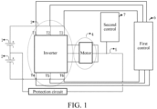
FIG. 1 is a block diagram of a heating circuit of a power battery according to an embodiment of the present disclosure; -
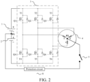
FIG. 2 is a specific circuit diagram of a heating circuit of a power battery according to an embodiment of the present disclosure; -
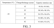
FIG. 3 is a schematic diagram of impact of a magnitude of an excitation current on a power battery capacity; -
FIG. 4 is a schematic diagram of impact of a frequency of an excitation current on a temperature rise rate; and -
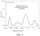
FIG. 5 to FIG. 8 are schematic diagrams of decomposition of an impedance spectroscopy of a power battery in different SOCs under the action of excitation currents of different frequencies. - The following describes in detail various exemplary embodiments of this specification with reference to the accompanying drawings.
- In fact, the following descriptions of at least one exemplary embodiment are merely illustrative, and in no way constitute any limitation on the embodiments of this specification and application or use of this specification.
- It should be noted that: similar reference signs or letters in the accompanying drawings indicate similar items. Therefore, once an item is defined in one accompanying drawing, the item does not need to be further discussed in the subsequent accompanying drawings.
- In an electric vehicle, an inverter is connected between a power battery and an alternating current motor. One of main functions of the inverter is to convert a direct current outputted by the power battery into an alternating current to drive the alternating current motor to rotate, so as to drive a wheel end to rotate. A power battery heating solution in the embodiments of the present disclosure utilizes a circuit topology structure between the power battery, the inverter, and the alternating current motor. The following describes, with reference to
FIG. 1 andFIG. 2 , a heating circuit of a power battery provided in the embodiments of the present disclosure. - The power battery includes a first
battery core group 1 and a secondbattery core group 2 connected in series. The heating circuit includes an inverter 3, an alternatingcurrent motor 4, and afirst controller 6. - The alternating
current motor 4 is star-connected. Three tail ends of three phase coils (a coil A, a coil B, and a coil C) are connected together as a common end. The common end is a neutral point P2. The neutral point P2 of the alternatingcurrent motor 4 is connected to a first connection point P1. The first connection point P1 is a connection point between the firstbattery core group 1 and the secondbattery core group 2. In an example, a battery pack includes the first battery core group and the second battery core group. The battery pack provides a main positive port, a main negative port, and a third port lead out of the first connection point P1 to the outside. The first connection point P1 is connected to the neutral point P2 of the alternatingcurrent motor 4 through the third port. In another example, the firstbattery core group 1 and the secondbattery core group 2 are different battery packs. - The first controller is configured to input a driving signal to the inverter 3 to control the inverter 3 to alternately conduct the first
battery core group 1 and the secondbattery core group 2 to the alternatingcurrent motor 4, to cause the first battery core group and the second battery core group to alternately charge each other. - In an example, referring to
FIG. 1 andFIG. 2 , the inverter 3 includes an insulated gate bipolar transistor (IGBT) transistor T1, an IGBT transistor T2, an IGBT transistor T3, an IGBT transistor T4, an IGBT transistor T5, and an IGBT transistor T6. The IGBT transistors T1 to T6 constitute three bridge arms. An IGBT is a composite voltage-driven power semiconductor device including a bipolar junction transistor (BJT) and a Metal-Oxide-Semiconductor Field Effect Transistor(MOSFET), and has advantages of a high input impedance of a metal-oxide-semiconductor field-effect transistor (MOSFET) and a low conduction voltage drop of a giant transistor (GTR). Referring toFIG. 2 , in the inverter 3, each IGBT transistor is further connected in anti-parallel with a diode. The diode can protect the circuit. In another embodiment, the IGBT transistors T1 to T6 may be respectively replaced with MOS transistors. - In an embodiment of the present disclosure, the IGBT transistor may output current signals of different frequencies and amplitudes in real time according to a frequency and a cycle of the driving signal. In an example, the driving signal outputted by the first controller is a pulse width modulation (PWM) driving signal, that is, a pulse wave signal with a variable duty cycle.
- In an embodiment of the present disclosure, referring to
FIG. 2 , the first controller outputs six driving signals Q1 to Q6. The driving signal Q1 is applied to the IGBT transistor T1, the driving signal Q2 is applied to the IGBT transistor T2, the driving signal Q3 is applied to the IGBT transistor T3, the driving signal Q4 is applied to the IGBT transistor T4, the driving signal Q5 is applied to the IGBT transistor T5, and the driving signal Q6 is applied to the IGBT transistor T6. The first controller alternately closes circuits from the firstbattery core group 1 and the secondbattery core group 2 to the alternatingcurrent motor 4 by applying the driving signals Q1 to Q6 to the IGBT transistors T1 to T6, to cause the firstbattery core group 1 and the secondbattery core group 2 to alternately charge each other. In an example, the firstbattery core group 1 discharges, the inverter 3 converts a direct current outputted by the firstbattery core group 1 into an alternating current and inputs the alternating current to the alternatingcurrent motor 4, and the alternatingcurrent motor 4 stores electric energy in a coil to charge the secondbattery core group 2. Then, the secondbattery core group 2 discharges, the inverter 3 converts a direct current outputted by the secondbattery core group 2 into an alternating current and inputs the alternating current to the alternatingcurrent motor 4, and the alternatingcurrent motor 4 stores the electric energy in the coil to charge the firstbattery core group 1. Through cyclical repetition of this process, the first battery core group and the second battery core group alternately charge each other. - In an example, a
switch 5 is connected in series between the neutral point P2 of the alternating current motor and the first connection point P1. The heating circuit further includes asecond controller 7. The second controller is configured to control an on-off state of theswitch 5, so that theswitch 5 is turned on when the power battery needs to be heated and is turned off when the power battery does not need to be heated, to ensure safety of a vehicle and the power battery. For example, the second controller controls theswitch 5 to be turned off in a traveling state of an electric vehicle, to ensure safety of traveling of the vehicle. - In an example, a
protection circuit 8, for example, a fuse, is connected in series between the neutral point P2 of the alternating current motor and the first connection point P1, to improve safety of the battery heating process. - In an example, a battery capacity of the first battery core group is the same as a battery capacity of the second battery core group. The arrangement of the first battery core group and the second battery core group having the same battery capacity facilitates simplification of a control logic algorithm and selection of related components of the heating circuit.
- According to the heating circuit of the power battery provided in the embodiments of the present disclosure, a circuit is added based on an original circuit topology structure of the electric vehicle. The circuit is from the neutral point of the alternating current motor to the connection point between the first battery core group and the second battery core group. A change to an original circuit is small, and the solution is simple and easy to implement.
- During heating of the power battery, a frequency and a magnitude of a charge/discharge current, that is, an excitation current, are limited by the related components. The heating circuit provided in the embodiments of the present disclosure enables a degree of limitation on the excitation current to be relatively small, making it possible to heat a battery with a relatively large excitation current. For example, if a limitation of a single coil of a motor on the excitation current is considered, assuming that an allowed maximum current value passing the single coil of the motor is 100 units, according to the heating circuit provided in the embodiments of the present disclosure, three coils simultaneously store energy and discharge, so that an upper limit of the excitation current may be 300 units.
- During heating of the power battery, control of the excitation current is extremely critical. Under the action of the relatively large excitation current, a temperature rise rate of the power battery is relatively fast.
FIG. 4 shows a capacity retention rate of lithium iron phosphate with a ternary battery under a self-heating condition. The inventor finds through a large quantity of experiments that, at a temperature of -20°C, the power battery is heated by using an excitation current of 1C, and a capacity retention rate is 99.0% to 99.94% after the power battery is heated for a preset quantity of times. In other words, a battery capacity is only 99.0% to 99.94% of an original battery capacity after the power battery is heated for the preset quantity of times. 1C is a current intensity when the battery fully discharges for one hour. The preset quantity of times is 200. For a case in which the power battery is heated by using a charge/discharge current of 2C to 5C, reference may also be made toFIG. 4 . In other words, as the excitation current increases, adverse impact on the battery capacity also increases. - The inventor finds through a large quantity of experiments that, an excessively high frequency of the excitation current affects heating efficiency, causing a temperature of the battery to rise slowly. This is due to inherent electrochemical characteristics of the battery. An impedance of the battery is larger under a low frequency current oscillation, and therefore a temperature rise effect is higher. However, during heating in a low temperature environment, low frequency excitation may lead to reduction of battery life and may even cause lithium precipitation. Referring to
FIG. 3 , the power battery is heated by using an excitation current of 2C, an excitation current of 3C, and an excitation current of 4C separately, and a frequency of the excitation current is set to vary from 1 Hz to 1000 Hz. It can be learned that a temperature rise rate is relatively high in a low frequency stage, and especially in an interval of 1 Hz to 100 Hz, the temperature rise rate of the battery is relatively high. -
FIG. 5 to FIG. 8 are schematic diagrams of decomposition of a battery impedance spectroscopy of a power battery in different SOCs under the action of excitation currents of different frequencies. A state of charge (SOC) is the remaining charge in the battery and is usually expressed as a percentage, that is, a percentage of the remaining quantity of electricity of the battery to a total capacity. A horizontal axis is a periodicity length of an excitation current in units of seconds, a reciprocal thereof is a frequency of the excitation current, and the frequency gradually decreases from left to right in a direction of the horizontal axis. A vertical axis is distribution of an impedance over time in units of ohms per second. It can be learned fromFIG. 5 to FIG. 8 that, in different SOCs, when a periodicity of the excitation current is in an interval of 0.01s to 0.1s (a frequency is in a range from 10 Hz to 100 Hz), there is an extremely large peak in the distribution of the impedance over time. It can be learned fromFIG. 5 to FIG. 8 that, in different SOCs, when the periodicity of the excitation current exceeds 1s (the frequency is less than 1 Hz), a relatively high lithium precipitation risk occurs. - In an embodiment of the present disclosure, the first controller obtains a battery status (a temperature, a quantity of electricity, a voltage) and a magnitude and a frequency of a charge/discharge current that are monitored by a vehicle measurement system, and dynamically adjusts the frequency or the current magnitude of the excitation current in real time according to a preset policy. The following describes a manner of controlling the excitation current, that is, the charge/discharge current, in this embodiment.
- In an embodiment of the present disclosure, a real-time current of the first
battery core group 1 is denoted as IA, and a real-time current of the secondbattery core group 2 is denoted as IB. That IA flows out of a positive electrode of the firstbattery core group 1 is denoted as a positive cycle, and that IA flows into the positive electrode of the firstbattery core group 1 is denoted as a negative cycle. That IB flows out of a positive electrode of the secondbattery core group 2 is denoted as a positive cycle, and that IB flows into the positive electrode of the secondbattery core group 2 is denoted as a negative cycle. - Policy 1: The first controller is further configured to adjust the driving signal, to cause a current intensity average value of the first battery core group to be in a range from 1C to 5C and a current intensity average value of the second battery core group to be in a range from 1C to 5C within a first time period, and the first time period is 60s. In other words, during heating of the power battery, within a time length of at least 60s, the current intensity average value of the first battery core group is in the range from 1C to 5C, and the current intensity average value of the second battery core group is in the range from 1C to 5C.
- A current intensity average value of a battery core group may be calculated through the following formula:

- Herein, "C" is a rate of a magnitude of the charge/discharge current of the battery, and 1C represents a current intensity when the battery fully discharges for one hour. For the first battery core group, 1C=CA/3600s, and CA is a rated capacity of the first battery core group in units of ampere hours. For the second battery core group, 1C=CB/3600s, and CB is a rated capacity of the second battery core group in units of ampere hours. In other words,


- IeffA is the current intensity average value of the first
battery core group 1 within the first time period, and IeffB is the current intensity average value of the secondbattery core group 2 within the first time period. - In the embodiments of the present disclosure, the excitation current is controlled to be in a range from 1C to 5C, so that heating efficiency can be ensured, and the adverse impact on the battery capacity is controlled within a relatively small range. In addition, over-charge or over-discharge occurring on a battery core in the low temperature environment can be further avoided, thereby ensuring safety of the battery core.
- In an example, the first controller is further configured to adjust the driving signal, to cause a quantity of times that a real-time current of the first battery core group is switched from a positive cycle to a negative cycle to be in a range from 1 to 1000 times and a quantity of times that a real-time current of the second battery core group is switched from a positive cycle to a negative cycle to be in a range from 1 to 1000 times within 1s. In other words, during heating of the power battery, a quantity of times that a real-time current of a battery core group is switched from the positive cycle to the negative cycle is in the range from 1 to 1000 times within a time length of at least 1s.
- In an example, the first controller is further configured to adjust the driving signal, to cause a quantity of times that a real-time current of the first battery core group is switched from a positive cycle to a negative cycle to be in a range from 5 to 1000 times and a quantity of times that a real-time current of the second battery core group is switched from a positive cycle to a negative cycle to be in a range from 5 to 1000 times within 1s. In other words, during heating of the power battery, a quantity of times that a real-time current of a battery core group is switched from the positive cycle to the negative cycle is in the range from 5 to 1000 times within a time length of at least 1s.
- In an example, the first controller is further configured to adjust the driving signal, to cause a quantity of times that a real-time current of the first battery core group is switched from a positive cycle to a negative cycle to be in a range from 1 to 100 times and a quantity of times that a real-time current of the second battery core group is switched from a positive cycle to a negative cycle to be in a range from 1 to 100 times within 1s. In other words, during heating of the power battery, a quantity of times that a real-time current of a battery core group is switched from the positive cycle to the negative cycle is in the range from 1 to 100 times within a time length of at least 1s.
- In an example, the first controller is further configured to adjust the driving signal, to cause a quantity of times that a real-time current of the first battery core group is switched from a positive cycle to a negative cycle to be in a range from 5 to 100 times and a quantity of times that a real-time current of the second battery core group is switched from a positive cycle to a negative cycle to be in a range from 5 to 100 times within 1s. In other words, during heating of the power battery, a quantity of times that a real-time current of a battery core group is switched from the positive cycle to the negative cycle is in the range from 5 to 100 times within a time length of at least 1s.
- In an example, the first controller is further configured to adjust the driving signal, to cause a quantity of times that a real-time current of the first battery core group is switched from a positive cycle to a negative cycle to be 10 times and a quantity of times that a real-time current of the second battery core group is switched from a positive cycle to a negative cycle to be 10 times within 1s. In other words, during heating of the power battery, a quantity of times that a real-time current of a battery core group is switched from the positive cycle to the negative cycle is 10 times within a time length of at least 1s.
- With reference to the content shown in
FIG. 4 andFIG. 5 toFIG. 8 , considering the adverse impact on the battery life and the lithium precipitation risk occurring on the excitation current in an excessively low frequency, in the embodiments of the present disclosure, a range of a safety frequency of the excitation current is set to 1 Hz or more, that is, a lower limit of the frequency of the excitation current is 1 Hz. Considering the heating efficiency, an upper limit of the frequency of the excitation current is set to 1000 Hz. In the embodiments of the present disclosure, several ranges are preferably selected from a range from 1 Hz to 1000 Hz. The quantity of times that the real-time current of the battery core group is switched from the positive cycle to the negative cycle within unit time is set in the foregoing manner, so that the heating efficiency can be taken into account, impact of heating on the battery life can be reduced, and a risk in a heating process can be reduced. - Policy 3: The first controller is further configured to adjust the driving signal, to cause a magnitude of a real-time current of the first battery core group to be the same as a magnitude of a real-time current of the second battery core group. That is, in a heating process, within at least a period of time, |IA|=|IB|. "| |"is a symbol of an absolute value.
- The magnitude of the real-time current of the first battery core group is the same as the magnitude of the real-time current of the second battery core group, which facilitates simplification of a control logic algorithm and selection of related components of the heating circuit and can reduce costs.
- The first controller is further configured to adjust the driving signal, to cause a target ratio to be greater than or equal to 0.3. The target ratio is a ratio of a first value to a second value, the first value is a smaller one of a real-time current absolute value of the first battery core group and a real-time current absolute value of the second battery core group, and the second value is a larger one of the real-time current absolute value of the first battery core group and the real-time current absolute value of the second battery core group.
- It can be learned from the
policy 4 that, the magnitude of the real-time current of the first battery core group and the magnitude of the real-time current of the second battery core group may be different based on the heating circuit provided in the embodiments of the present disclosure. The ratio of the smaller one of the real-time current absolute value of the first battery core group and the real-time current absolute value of the second battery core group to the larger one of the real-time current absolute value of the first battery core group and the real-time current absolute value of the second battery core group is controlled to be 0.3 or more, so that the magnitude of the real-time current of the first battery core group and the magnitude of the real-time current of the second battery core group do not differ excessively. In this way, heating of the power battery can also be relatively well implemented, and is relatively easy to implement technically. - In the embodiments of the present disclosure, the foregoing policies may be implemented in superposition without conflict, to achieve a better effect.
- In an embodiment of the present disclosure, the first controller may adjust a duty cycle and/or a frequency of the driving signal, to implement the foregoing control policies. For example, the first controller adjusts the duty cycle of the driving signal, to adjust the magnitude of the excitation current. For example, the first controller adjusts the frequency of the driving signal, to control a quantity of times that the excitation current is switched from the positive cycle to the negative cycle within a period of time.
- In the embodiments of the present disclosure, through the foregoing policies, temperature rise efficiency and safety in a self-heating process are taken into account, the power battery can be heated efficiently without causing an excessively large damage to the battery life, and safety of the battery is ensured.
- A first controller in an embodiment of the present disclosure may include a processor, a memory, and programs or instructions stored in the memory and runnable on the processor, where the programs or the instructions are executed by the processor to implement the heating control policy according to any one of the foregoing embodiments.
- An embodiment of the present disclosure provides a vehicle, including a power battery and the heating circuit of the power battery according to any one of the foregoing embodiments.
- The embodiments of the present disclosure are all described in a progressive manner. For same or similar parts in the embodiments, reference may be made to these embodiments. Each embodiment focuses on a difference from other embodiments. For the electric vehicle embodiments, reference may be made to partial description in the method embodiments.
- Specific embodiments of this specification are described above. Other embodiments fall within the scope of the appended claims. In some cases, the actions or steps recorded in the claims may be performed in sequences different from those in the embodiments and an expected result may still be achieved. In addition, the processes depicted in the accompanying drawings are not necessarily performed in the specific order or successively to achieve an expected result. In some implementations, multitasking and parallel processing may be feasible or beneficial.
- The embodiments of this specification may be a system, a method, and/or a computer program product. The computer program product may include a computer-readable storage medium, having computer instructions used for causing the processor to implement the aspects of the embodiments of this specification stored therein.
- The computer-readable storage medium may be a physical device that can retain and store computer instructions used by a computer instruction-executing device. The computer-readable storage medium may be, for example, but is not limited to, an electrical storage device, a magnetic storage device, an optical storage device, an electromagnetic storage device, a semiconductor storage device, or any appropriate combination of the above. In a more specific example (a non-exhaustive list), the computer-readable storage medium includes a portable computer disk, a hard disk, a random access memory (RAM), a read-only memory (ROM), an erasable programmable read-only memory (EPROM or flash memory), a static random access memory (SRAM), a portable compact disk read-only memory (CD-ROM), a digital versatile disk (DVD), a memory stick, a floppy disk, a mechanical coding device such as a punched card or protrusion in a groove in which computer instructions are stored, and any appropriate combination of the above. The computer-readable storage medium as used here is not explained as a transient signal itself, such as a radio wave or other electromagnetic waves propagated freely, an electromagnetic wave propagated through a waveguide or other transmission media (e.g., a light pulse propagated through an optical fiber cable), or an electrical signal transmitted over a wire.
- The computer instructions described herein may be downloaded to various computing/processing devices from the computer-readable storage medium or may be downloaded to an external computer or an external storage device through a network such as an Internet, a local area network, a wide area network, and/or a wireless network. The network may include copper transmission cables, optical fiber transmission fibers, wireless transmission, routers, firewalls, switches, gateway computers, and/or edge servers. A network adapter card or network interface in each computing/processing device receives computer instructions from the network and forwards the computer instructions for storage in a computer-readable storage medium in each computing/processing device.
- The flowcharts and block diagrams in the accompanying drawings illustrate architectures, functions, and operations that may be implemented for systems, methods and computer program products according to a plurality of embodiments of this specification. In this regard, each box in a flowchart or a block diagram may represent a module, a program segment or a part of computer instruction. The module, the program segment or the part of computer instruction includes one or more executable computer instructions used for implementing specified logic functions. In some implementations used as substitutes, functions annotated in boxes may alternatively occur in a sequence different from that annotated in an accompanying drawing. For example, actually two continuous boxes shown in succession may be performed basically in parallel, and sometimes the two boxes may be performed in a reverse sequence. This is determined by a related function. Each box in a block diagram and/or a flowchart and a combination of boxes in the block diagram and/or the flowchart may be implemented by using a dedicated hardware-based system configured to perform a specified function or action, or may be implemented by using a combination of dedicated hardware and a computer instruction. It is well known to a person skilled in the art that an implementation in hardware, an implementation in software, and an implementation in a combination of software and hardware are equivalent.
- The embodiments of this specification are described above, and the foregoing descriptions are exemplary but not exhaustive and are not limited to the disclosed embodiments. Without departing from the scope of the described embodiments, many modifications and variations are apparent to a person of ordinary skill in the technical field. The selected terms used herein is intended to best explain the principles of the embodiments, practical applications, or improvements of technologies in the market, or to enable other persons of ordinary skill in the technical field to understand the embodiments disclosed herein.
Claims (20)
- A heating circuit of a power battery, wherein the power battery comprises a first battery core group (1) and a second battery core group (2) connected in series, the heating circuit comprising an inverter (3), an alternating current motor (4), and a first controller (6);a neutral point (P2) of the alternating current motor (4) being connected to a first connection point (P1), the first connection point (P1) being a connection point between the first battery core group (1) and the second battery core group (2); andthe first controller (6) being configured to input a driving signal to the inverter (3) to control the inverter (3) to alternately connect the first battery core group (1) and the second battery core group (2) to the alternating current motor (4), to cause the first battery core group (1) and the second battery core group (2) to alternately charge each other.
- The heating circuit according to claim 1, wherein a switch (5) is connected in series between the neutral point (P2) of the alternating current motor (4) and the first connection point (P1), the heating circuit further comprising a second controller, the second controller being configured to control an on-off state of the switch.
- The heating circuit according to claim 1 or 2, wherein a protection circuit (8) is connected in series between the neutral point (P2) of the alternating current motor (4) and the first connection point (P1).
- The heating circuit according to any one of claims 1 to 3, wherein a battery capacity of the first battery core group (1) is the same as a battery capacity of the second battery core group (2).
- The heating circuit according to any one of claims 1 to 4, wherein the first controller (6) is further configured to adjust the driving signal, to cause a current intensity average value of the first battery core group (1) to be in a range from 1C to 5C and a current intensity average value of the second battery core group (2) to be in a range from 1C to 5C within a first time period, and the first time period is 60s.
- The heating circuit according to any one of claims 1 to 5, wherein the first controller (6) is further configured to adjust the driving signal, to cause a quantity of times that a real-time current of the first battery core group (1) is switched from a positive cycle to a negative cycle to be in a range from 1 to 1000 times and a quantity of times that a real-time current of the second battery core group (2) is switched from a positive cycle to a negative cycle to be in a range from 1 to 1000 times within 1s.
- The heating circuit according to any one of claims 1 to 5, wherein the first controller (6) is further configured to adjust the driving signal, to cause a quantity of times that a real-time current of the first battery core group (1) is switched from a positive cycle to a negative cycle to be in a range from 1 to 100 times and a quantity of times that a real-time current of the second battery core group (2) is switched from a positive cycle to a negative cycle to be in a range from 1 to 100 times within 1s.
- The heating circuit according to any one of claims 1 to 5, wherein the first controller (6) is further configured to adjust the driving signal, to cause a quantity of times that a real-time current of the first battery core group (1) is switched from a positive cycle to a negative cycle to be 10 times and a quantity of times that a real-time current of the second battery core group (2) is switched from a positive cycle to a negative cycle to be 10 times within 1s.
- The heating circuit according to any one of claims 1 to 5, wherein the first controller (6) is further configured to adjust the driving signal, to cause a magnitude of a real-time current of the first battery core group (1) to be the same as a magnitude of a real-time current of the second battery core group (2).
- The heating circuit according to any one of claims 1 to 5, wherein the first controller (6) is further configured to adjust the driving signal, to cause a target ratio to be greater than or equal to 0.3, the target ratio being a ratio of a first value to a second value, the first value being a smaller one of a real-time current absolute value of the first battery core group (1) and a real-time current absolute value of the second battery core group (2), and the second value being a larger one of the real-time current absolute value of the first battery core group (1) and the real-time current absolute value of the second battery core group (2).
- The heating circuit according to any one of claims 5 to 10, wherein when being configured to adjust the driving signal, the first controller (6) is configured to adjust a duty cycle and/or a frequency of the driving signal.
- An electric vehicle, comprising a power battery and a heating circuit,the power battery comprising a first battery core group (1) and a second battery core group (2) connected in series, and the heating circuit comprising an inverter (3), an alternating current motor (4), and a first controller (6);a neutral point (P2) of the alternating current motor (4) being connected to a first connection point (P1), the first connection point (P1) being a connection point between the first battery core group (1) and the second battery core group (2); andthe first controller (6) being configured to input a driving signal to the inverter (3) to control the inverter to alternately connect the first battery core group (1) and the second battery core group (2) to the alternating current motor (4), to cause the first battery core group (1) and the second battery core group (2) to alternately charge each other.
- The electric vehicle according to claim 12, wherein a switch (5) is connected in series between the neutral point (P2) of the alternating current motor (4) and the first connection point (P1), the heating circuit further comprises a second controller, and the second controller is configured to control an on-off state of the switch.
- The electric vehicle according to claim 12 or 13, wherein a protection circuit (8) is connected in series between the neutral point (P2) of the alternating current motor (4) and the first connection point (P1).
- The electric vehicle according to any one of claims 12 to 14, wherein the first controller (6) is further configured to adjust the driving signal, to cause a current intensity average value of the first battery core group (1) to be in a range from 1C to 5C and a current intensity average value of the second battery core group (2) to be in a range from 1C to 5C within a first time period, and the first time period is 60s.
- The electric vehicle according to any one of claims 12 to 14, wherein the first controller (6) is further configured to adjust the driving signal, to cause a quantity of times that a real-time current of the first battery core group (1) is switched from a positive cycle to a negative cycle to be in a range from 1 to 1000 times and a quantity of times that a real-time current of the second battery core group (2) is switched from a positive cycle to a negative cycle to be in a range from 1 to 1000 times within 1s.
- The electric vehicle according to any one of claims 12 to 14, wherein the first controller (6) is further configured to adjust the driving signal, to cause a quantity of times that a real-time current of the first battery core group (1) is switched from a positive cycle to a negative cycle to be in a range from 1 to 100 times and a quantity of times that a real-time current of the second battery core group (2) is switched from a positive cycle to a negative cycle to be in a range from 1 to 100 times within 1s.
- The electric vehicle according to any one of claims 12 to 14, wherein the first controller (6) is further configured to adjust the driving signal, to cause a quantity of times that a real-time current of the first battery core group (1) is switched from a positive cycle to a negative cycle to be 10 times and a quantity of times that a real-time current of the second battery core group (2) is switched from a positive cycle to a negative cycle to be 10 times within 1s.
- The electric vehicle according to any one of claims 12 to 14, wherein the first controller (6) is further configured to adjust the driving signal, to cause a magnitude of a real-time current of the first battery core group (1) to be the same as a magnitude of a real-time current of the second battery core group (2).
- The electric vehicle according to any one of claims 12 to 14, wherein the first controller (6) is further configured to adjust the driving signal, to cause a target ratio to be greater than or equal to 0.3, the target ratio being a ratio of a first value to a second value, the first value being a smaller one of a real-time current absolute value of the first battery core group (1) and a real-time current absolute value of the second battery core group (2), and the second value being a larger one of the real-time current absolute value of the first battery core group (1) and the real-time current absolute value of the second battery core group (2).
Applications Claiming Priority (2)
| Application Number | Priority Date | Filing Date | Title |
|---|---|---|---|
| CN202210112694.2A CN116552335B (en) | 2022-01-29 | 2022-01-29 | Heating circuit of power battery and electric vehicle |
| PCT/CN2022/137555 WO2023142709A1 (en) | 2022-01-29 | 2022-12-08 | Heating circuit of power battery, and electric vehicle |
Publications (2)
| Publication Number | Publication Date |
|---|---|
| EP4438396A1 true EP4438396A1 (en) | 2024-10-02 |
| EP4438396A4 EP4438396A4 (en) | 2025-03-19 |
Family
ID=87470359
Family Applications (1)
| Application Number | Title | Priority Date | Filing Date |
|---|---|---|---|
| EP22923499.2A Pending EP4438396A4 (en) | 2022-01-29 | 2022-12-08 | POWER BATTERY HEATING CIRCUIT, AND ELECTRIC VEHICLE |
Country Status (7)
| Country | Link |
|---|---|
| US (1) | US20240351477A1 (en) |
| EP (1) | EP4438396A4 (en) |
| JP (1) | JP2025503861A (en) |
| KR (1) | KR20240112350A (en) |
| CN (1) | CN116552335B (en) |
| CA (1) | CA3243221A1 (en) |
| WO (1) | WO2023142709A1 (en) |
Families Citing this family (2)
| Publication number | Priority date | Publication date | Assignee | Title |
|---|---|---|---|---|
| CN117002326B (en) * | 2022-04-29 | 2024-10-11 | 比亚迪股份有限公司 | Battery heating system and electric vehicle |
| CN119519017A (en) * | 2023-08-25 | 2025-02-25 | 比亚迪股份有限公司 | Battery charging circuit and electric vehicle |
Family Cites Families (16)
| Publication number | Priority date | Publication date | Assignee | Title |
|---|---|---|---|---|
| US9209644B2 (en) * | 2010-07-30 | 2015-12-08 | Byd Company Limited | Circuits and methods for heating batteries in series using resonance components in series |
| JP5865736B2 (en) * | 2012-03-05 | 2016-02-17 | 株式会社日本自動車部品総合研究所 | Power converter |
| CN105762434B (en) * | 2016-05-16 | 2018-12-07 | 北京理工大学 | A kind of power-supply system and vehicle with self heating function |
| JP7041567B2 (en) * | 2018-03-27 | 2022-03-24 | 株式会社Subaru | Vehicle power supply |
| CN111355435B (en) * | 2018-12-21 | 2022-04-15 | 比亚迪股份有限公司 | Motor control circuit, vehicle and heating method thereof |
| JP7370223B2 (en) * | 2019-01-24 | 2023-10-27 | 株式会社Soken | power converter |
| CN109995102B (en) * | 2019-03-01 | 2022-04-01 | 中国第一汽车股份有限公司 | Power battery equalization system for electric automobile and control method |
| CN110015202B (en) * | 2019-03-28 | 2021-01-22 | 清华大学 | Electric automobile battery heating method |
| CN110116653B (en) * | 2019-04-19 | 2024-02-09 | 清华大学 | Driving system and driving circuit of electric automobile and heating method of battery of electric automobile |
| CN110962692B (en) * | 2019-06-24 | 2020-12-11 | 宁德时代新能源科技股份有限公司 | Battery pack heating system and control method thereof |
| JP7232747B2 (en) * | 2019-12-10 | 2023-03-03 | 株式会社Soken | power converter |
| CN113733986A (en) * | 2020-05-29 | 2021-12-03 | 比亚迪股份有限公司 | Battery self-heating device, control method thereof and vehicle |
| KR20220006271A (en) * | 2020-07-08 | 2022-01-17 | 현대자동차주식회사 | System and method for increasing temperature of battery |
| CN112103595A (en) * | 2020-08-31 | 2020-12-18 | 上海交通大学 | Vehicle power battery preheating device and control method thereof |
| CN114566740B (en) * | 2022-04-28 | 2022-08-09 | 比亚迪股份有限公司 | Heating systems for power batteries and electric vehicles |
| CN216980690U (en) * | 2022-04-28 | 2022-07-15 | 比亚迪股份有限公司 | Heating systems for power batteries and electric vehicles |
-
2022
- 2022-01-29 CN CN202210112694.2A patent/CN116552335B/en active Active
- 2022-12-08 JP JP2024539456A patent/JP2025503861A/en active Pending
- 2022-12-08 KR KR1020247021753A patent/KR20240112350A/en active Pending
- 2022-12-08 CA CA3243221A patent/CA3243221A1/en active Pending
- 2022-12-08 EP EP22923499.2A patent/EP4438396A4/en active Pending
- 2022-12-08 WO PCT/CN2022/137555 patent/WO2023142709A1/en not_active Ceased
-
2024
- 2024-06-28 US US18/759,652 patent/US20240351477A1/en active Pending
Also Published As
| Publication number | Publication date |
|---|---|
| JP2025503861A (en) | 2025-02-06 |
| WO2023142709A1 (en) | 2023-08-03 |
| CN116552335B (en) | 2024-10-11 |
| CA3243221A1 (en) | 2025-04-10 |
| EP4438396A4 (en) | 2025-03-19 |
| KR20240112350A (en) | 2024-07-18 |
| CN116552335A (en) | 2023-08-08 |
| US20240351477A1 (en) | 2024-10-24 |
Similar Documents
| Publication | Publication Date | Title |
|---|---|---|
| US20240351477A1 (en) | Heating circuit of power battery and electric vehicle | |
| JP7844800B2 (en) | Heating system for heating power batteries, and electric vehicles | |
| US20230327596A1 (en) | Power conversion apparatus | |
| CN114889494B (en) | Battery heating device and car | |
| US10193192B2 (en) | Structure for modulating the voltage of a battery and the active equilibration thereof | |
| US10836264B2 (en) | Drive system | |
| CN113745703B (en) | Heating methods and devices for power batteries and vehicles | |
| KR102254782B1 (en) | Charging apparatus | |
| EP3412493B1 (en) | Electric motor drive apparatus and electric automobile | |
| US20250242723A1 (en) | Battery self-heating system, electrical device, and vehicle | |
| TW202120351A (en) | Battery system for a motor vehicle, method for operating a battery system, and motor vehicle | |
| Liu et al. | Amplitude–frequency decoupled heater and integrated strategies for automotive batteries based on inverter and motor | |
| KR20240172214A (en) | Battery self-heating control method and system, and electric vehicle | |
| CN118618148A (en) | Battery heating control method and related equipment | |
| Pan et al. | A novel discharging control strategy for modular multilevel converter submodules without using external circuit | |
| Pirooz et al. | Battery voltage equalisation using single‐phase cascaded H‐bridge converters | |
| CN115195534A (en) | Battery heating circuit, battery heating method and electric vehicle | |
| US12630056B2 (en) | Battery self-heating control method and system, and electric vehicle | |
| Bagheri et al. | Efficiency Improvment of Toyota Prius Power Train Using a 3Level NPC and Selected Harmonic Elimination Technique | |
| Chindamani et al. | Power Balancing in Four-Wheel Drive EV Using Carrier-Based PWM | |
| Hasegawa et al. | Battery Internal-Heating Method via SW Mode Switching of the Drive Inverter During Electric Vehicle Stoppage | |
| US20180342960A1 (en) | Power converter | |
| Delhotal | Observer-based fault detection and isolation for motor drive inverters | |
| US20250293532A1 (en) | Method for selecting an inductor and a pair of fet switches for an active battery cell equalization circuit | |
| Hasegawa et al. | Characteristics of Battery-Internal-Heating Method Involving Dq-Axis Current Pulsation in Permanent Magnet Synchronous Motors During Electric Vehicle Operation |
Legal Events
| Date | Code | Title | Description |
|---|---|---|---|
| STAA | Information on the status of an ep patent application or granted ep patent |
Free format text: STATUS: THE INTERNATIONAL PUBLICATION HAS BEEN MADE |
|
| PUAI | Public reference made under article 153(3) epc to a published international application that has entered the european phase |
Free format text: ORIGINAL CODE: 0009012 |
|
| STAA | Information on the status of an ep patent application or granted ep patent |
Free format text: STATUS: REQUEST FOR EXAMINATION WAS MADE |
|
| 17P | Request for examination filed |
Effective date: 20240628 |
|
| AK | Designated contracting states |
Kind code of ref document: A1 Designated state(s): AL AT BE BG CH CY CZ DE DK EE ES FI FR GB GR HR HU IE IS IT LI LT LU LV MC ME MK MT NL NO PL PT RO RS SE SI SK SM TR |
|
| A4 | Supplementary search report drawn up and despatched |
Effective date: 20250217 |
|
| RIC1 | Information provided on ipc code assigned before grant |
Ipc: H01M 10/6571 20140101ALI20250211BHEP Ipc: B60L 58/27 20190101AFI20250211BHEP |
|
| DAV | Request for validation of the european patent (deleted) | ||
| DAX | Request for extension of the european patent (deleted) |