EP4438384A1 - Method and system for controlling electric mobility - Google Patents
Method and system for controlling electric mobility Download PDFInfo
- Publication number
- EP4438384A1 EP4438384A1 EP23185909.1A EP23185909A EP4438384A1 EP 4438384 A1 EP4438384 A1 EP 4438384A1 EP 23185909 A EP23185909 A EP 23185909A EP 4438384 A1 EP4438384 A1 EP 4438384A1
- Authority
- EP
- European Patent Office
- Prior art keywords
- electric mobility
- state
- started
- electric
- mobility
- Prior art date
- Legal status (The legal status is an assumption and is not a legal conclusion. Google has not performed a legal analysis and makes no representation as to the accuracy of the status listed.)
- Pending
Links
Images


Classifications
-
- B—PERFORMING OPERATIONS; TRANSPORTING
- B62—LAND VEHICLES FOR TRAVELLING OTHERWISE THAN ON RAILS
- B62M—RIDER PROPULSION OF WHEELED VEHICLES OR SLEDGES; POWERED PROPULSION OF SLEDGES OR SINGLE-TRACK CYCLES; TRANSMISSIONS SPECIALLY ADAPTED FOR SUCH VEHICLES
- B62M6/00—Rider propulsion of wheeled vehicles with additional source of power, e.g. combustion engine or electric motor
- B62M6/40—Rider propelled cycles with auxiliary electric motor
- B62M6/45—Control or actuating devices therefor
-
- B—PERFORMING OPERATIONS; TRANSPORTING
- B60—VEHICLES IN GENERAL
- B60L—PROPULSION OF ELECTRICALLY-PROPELLED VEHICLES; SUPPLYING ELECTRIC POWER FOR AUXILIARY EQUIPMENT OF ELECTRICALLY-PROPELLED VEHICLES; ELECTRODYNAMIC BRAKE SYSTEMS FOR VEHICLES IN GENERAL; MAGNETIC SUSPENSION OR LEVITATION FOR VEHICLES; MONITORING OPERATING VARIABLES OF ELECTRICALLY-PROPELLED VEHICLES; ELECTRIC SAFETY DEVICES FOR ELECTRICALLY-PROPELLED VEHICLES
- B60L50/00—Electric propulsion with power supplied within the vehicle
- B60L50/20—Electric propulsion with power supplied within the vehicle using propulsion power generated by humans or animals
-
- B—PERFORMING OPERATIONS; TRANSPORTING
- B62—LAND VEHICLES FOR TRAVELLING OTHERWISE THAN ON RAILS
- B62M—RIDER PROPULSION OF WHEELED VEHICLES OR SLEDGES; POWERED PROPULSION OF SLEDGES OR SINGLE-TRACK CYCLES; TRANSMISSIONS SPECIALLY ADAPTED FOR SUCH VEHICLES
- B62M6/00—Rider propulsion of wheeled vehicles with additional source of power, e.g. combustion engine or electric motor
- B62M6/40—Rider propelled cycles with auxiliary electric motor
- B62M6/45—Control or actuating devices therefor
- B62M6/50—Control or actuating devices therefor characterised by detectors or sensors, or arrangement thereof
-
- B—PERFORMING OPERATIONS; TRANSPORTING
- B60—VEHICLES IN GENERAL
- B60L—PROPULSION OF ELECTRICALLY-PROPELLED VEHICLES; SUPPLYING ELECTRIC POWER FOR AUXILIARY EQUIPMENT OF ELECTRICALLY-PROPELLED VEHICLES; ELECTRODYNAMIC BRAKE SYSTEMS FOR VEHICLES IN GENERAL; MAGNETIC SUSPENSION OR LEVITATION FOR VEHICLES; MONITORING OPERATING VARIABLES OF ELECTRICALLY-PROPELLED VEHICLES; ELECTRIC SAFETY DEVICES FOR ELECTRICALLY-PROPELLED VEHICLES
- B60L15/00—Methods, circuits, or devices for controlling the traction-motor speed of electrically-propelled vehicles
- B60L15/20—Methods, circuits, or devices for controlling the traction-motor speed of electrically-propelled vehicles for control of the vehicle or its driving motor to achieve a desired performance, e.g. speed, torque, programmed variation of speed
- B60L15/2072—Methods, circuits, or devices for controlling the traction-motor speed of electrically-propelled vehicles for control of the vehicle or its driving motor to achieve a desired performance, e.g. speed, torque, programmed variation of speed for drive off
- B60L15/2081—Methods, circuits, or devices for controlling the traction-motor speed of electrically-propelled vehicles for control of the vehicle or its driving motor to achieve a desired performance, e.g. speed, torque, programmed variation of speed for drive off for drive off on a slope
-
- B—PERFORMING OPERATIONS; TRANSPORTING
- B62—LAND VEHICLES FOR TRAVELLING OTHERWISE THAN ON RAILS
- B62J—CYCLE SADDLES OR SEATS; AUXILIARY DEVICES OR ACCESSORIES SPECIALLY ADAPTED TO CYCLES AND NOT OTHERWISE PROVIDED FOR, e.g. ARTICLE CARRIERS OR CYCLE PROTECTORS
- B62J45/00—Electrical equipment arrangements specially adapted for use as accessories on cycles, not otherwise provided for
- B62J45/40—Sensor arrangements; Mounting thereof
- B62J45/41—Sensor arrangements; Mounting thereof characterised by the type of sensor
-
- H—ELECTRICITY
- H02—GENERATION; CONVERSION OR DISTRIBUTION OF ELECTRIC POWER
- H02K—DYNAMO-ELECTRIC MACHINES
- H02K7/00—Arrangements for handling mechanical energy structurally associated with dynamo-electric machines, e.g. structural association with mechanical driving motors or auxiliary dynamo-electric machines
- H02K7/18—Structural association of electric generators with mechanical driving motors, e.g. with turbines
- H02K7/1807—Rotary generators
- H02K7/1846—Rotary generators structurally associated with wheels or associated parts
-
- B—PERFORMING OPERATIONS; TRANSPORTING
- B60—VEHICLES IN GENERAL
- B60L—PROPULSION OF ELECTRICALLY-PROPELLED VEHICLES; SUPPLYING ELECTRIC POWER FOR AUXILIARY EQUIPMENT OF ELECTRICALLY-PROPELLED VEHICLES; ELECTRODYNAMIC BRAKE SYSTEMS FOR VEHICLES IN GENERAL; MAGNETIC SUSPENSION OR LEVITATION FOR VEHICLES; MONITORING OPERATING VARIABLES OF ELECTRICALLY-PROPELLED VEHICLES; ELECTRIC SAFETY DEVICES FOR ELECTRICALLY-PROPELLED VEHICLES
- B60L2200/00—Type of vehicles
- B60L2200/12—Bikes
-
- B—PERFORMING OPERATIONS; TRANSPORTING
- B60—VEHICLES IN GENERAL
- B60L—PROPULSION OF ELECTRICALLY-PROPELLED VEHICLES; SUPPLYING ELECTRIC POWER FOR AUXILIARY EQUIPMENT OF ELECTRICALLY-PROPELLED VEHICLES; ELECTRODYNAMIC BRAKE SYSTEMS FOR VEHICLES IN GENERAL; MAGNETIC SUSPENSION OR LEVITATION FOR VEHICLES; MONITORING OPERATING VARIABLES OF ELECTRICALLY-PROPELLED VEHICLES; ELECTRIC SAFETY DEVICES FOR ELECTRICALLY-PROPELLED VEHICLES
- B60L2200/00—Type of vehicles
- B60L2200/14—Vehicles with one wheel only
-
- B—PERFORMING OPERATIONS; TRANSPORTING
- B60—VEHICLES IN GENERAL
- B60L—PROPULSION OF ELECTRICALLY-PROPELLED VEHICLES; SUPPLYING ELECTRIC POWER FOR AUXILIARY EQUIPMENT OF ELECTRICALLY-PROPELLED VEHICLES; ELECTRODYNAMIC BRAKE SYSTEMS FOR VEHICLES IN GENERAL; MAGNETIC SUSPENSION OR LEVITATION FOR VEHICLES; MONITORING OPERATING VARIABLES OF ELECTRICALLY-PROPELLED VEHICLES; ELECTRIC SAFETY DEVICES FOR ELECTRICALLY-PROPELLED VEHICLES
- B60L2200/00—Type of vehicles
- B60L2200/16—Single-axle vehicles
-
- B—PERFORMING OPERATIONS; TRANSPORTING
- B60—VEHICLES IN GENERAL
- B60L—PROPULSION OF ELECTRICALLY-PROPELLED VEHICLES; SUPPLYING ELECTRIC POWER FOR AUXILIARY EQUIPMENT OF ELECTRICALLY-PROPELLED VEHICLES; ELECTRODYNAMIC BRAKE SYSTEMS FOR VEHICLES IN GENERAL; MAGNETIC SUSPENSION OR LEVITATION FOR VEHICLES; MONITORING OPERATING VARIABLES OF ELECTRICALLY-PROPELLED VEHICLES; ELECTRIC SAFETY DEVICES FOR ELECTRICALLY-PROPELLED VEHICLES
- B60L2200/00—Type of vehicles
- B60L2200/22—Microcars, e.g. golf cars
-
- B—PERFORMING OPERATIONS; TRANSPORTING
- B60—VEHICLES IN GENERAL
- B60L—PROPULSION OF ELECTRICALLY-PROPELLED VEHICLES; SUPPLYING ELECTRIC POWER FOR AUXILIARY EQUIPMENT OF ELECTRICALLY-PROPELLED VEHICLES; ELECTRODYNAMIC BRAKE SYSTEMS FOR VEHICLES IN GENERAL; MAGNETIC SUSPENSION OR LEVITATION FOR VEHICLES; MONITORING OPERATING VARIABLES OF ELECTRICALLY-PROPELLED VEHICLES; ELECTRIC SAFETY DEVICES FOR ELECTRICALLY-PROPELLED VEHICLES
- B60L2200/00—Type of vehicles
- B60L2200/24—Personal mobility vehicles
-
- B—PERFORMING OPERATIONS; TRANSPORTING
- B60—VEHICLES IN GENERAL
- B60L—PROPULSION OF ELECTRICALLY-PROPELLED VEHICLES; SUPPLYING ELECTRIC POWER FOR AUXILIARY EQUIPMENT OF ELECTRICALLY-PROPELLED VEHICLES; ELECTRODYNAMIC BRAKE SYSTEMS FOR VEHICLES IN GENERAL; MAGNETIC SUSPENSION OR LEVITATION FOR VEHICLES; MONITORING OPERATING VARIABLES OF ELECTRICALLY-PROPELLED VEHICLES; ELECTRIC SAFETY DEVICES FOR ELECTRICALLY-PROPELLED VEHICLES
- B60L2250/00—Driver interactions
- B60L2250/24—Driver interactions by lever actuation
-
- B—PERFORMING OPERATIONS; TRANSPORTING
- B62—LAND VEHICLES FOR TRAVELLING OTHERWISE THAN ON RAILS
- B62K—CYCLES; CYCLE FRAMES; CYCLE STEERING DEVICES; RIDER-OPERATED TERMINAL CONTROLS SPECIALLY ADAPTED FOR CYCLES; CYCLE AXLE SUSPENSIONS; CYCLE SIDECARS, FORECARS, OR THE LIKE
- B62K23/00—Rider-operated controls specially adapted for cycles, i.e. means for initiating control operations, e.g. levers, grips
- B62K23/02—Rider-operated controls specially adapted for cycles, i.e. means for initiating control operations, e.g. levers, grips hand actuated
-
- B—PERFORMING OPERATIONS; TRANSPORTING
- B62—LAND VEHICLES FOR TRAVELLING OTHERWISE THAN ON RAILS
- B62L—BRAKES SPECIALLY ADAPTED FOR CYCLES
- B62L3/00—Brake-actuating mechanisms; Arrangements thereof
-
- H—ELECTRICITY
- H02—GENERATION; CONVERSION OR DISTRIBUTION OF ELECTRIC POWER
- H02P—CONTROL OR REGULATION OF ELECTRIC MOTORS, ELECTRIC GENERATORS OR DYNAMO-ELECTRIC CONVERTERS; CONTROLLING TRANSFORMERS, REACTORS OR CHOKE COILS
- H02P1/00—Arrangements for starting electric motors or dynamo-electric converters
- H02P1/16—Arrangements for starting electric motors or dynamo-electric converters for starting dynamo-electric motors or dynamo-electric converters
Definitions
- the present disclosure generally relates to a method and system for controlling or driving an electric mobility. More specifically, the present disclosure relates to a method and system for controlling or driving an electric mobility that can check or confirm user's intention to start the electric mobility and control the electric mobility to start only if the user has the intention to start the electric mobility.
- An electric mobility such as an electric transport, an electric bicycle or an electric cargo (e-cargo), assists a person, or drives the electric mobility by driving a motor with electricity.
- a PAS (Pedal Assistance System) type method uses the power of a motor to assist a person stepping on a pedal to drive the wheels, and a throttle type method drives the wheels only with the power of the motor by pulling a handle.
- PAS/throttle type electric mobility that supports both the PAS type method and the throttle type method.
- a driving control method of an electric mobility may comprise: a brake operation determination step of determining whether a brake is operated in a stationary state in which the electric mobility is stopped; a brake operation state conversion step of converting the electric mobility into a brake operation state if it is determined that the brake is operated in the brake operation determination step; a brake release determination step of determining whether the brake is released in the brake operation state; and a standby state conversion step of converting the electric mobility into a standby state in which the electric mobility can be started if it is determined that the brake is released in the brake release determination step.
- the driving control method may further comprise a stationary state conversion step of controlling the electric mobility to be converted into the stationary state if a predetermined time has elapsed without starting the electric mobility in the standby state.
- the driving control method may further comprise a driving state conversion step of converting the electric mobility into a driving state in which a motor is being driven if a pedal or a throttle mounted at the electric mobility is operated before a predetermined time elapses in the standby state.
- the electric mobility may be converted into the brake operation state.
- the predetermined time may be set within a range from 5 seconds to 10 seconds.
- the electric mobility may be converted into the standby state.
- the electric mobility may not be started even if the pedal or the throttle mounted at the electric mobility is operated.
- a driving control method of an electric mobility comprises: a start button operation determination step of determining whether a start button installed at the electric mobility is operated in a stationary state in which the electric mobility is stopped; and a standby state conversion step of converting the electric mobility into a standby state in which the electric mobility can be started if it is determined that the start button is operated in the start button operation determination step.
- start button may be located on an interface installed at the electric mobility.
- a driving system of an electric mobility comprises: a generator configured to generate voltage by driving a pedal or operating a throttle; a motor mounted at at least one of front and rear wheels of the electric mobility to provide rotational force to a wheel; and a controller configured to control the driving system, wherein the controller comprises: a starting intention determination unit configured to determine a user's intention to start in a stationary state in which the electric mobility is stopped; and a standby state conversion unit configured to convert the electric mobility into a standby state in which the electric mobility can be started if it is determined that there is the user's intention to start in the starting intention determination unit.
- the starting intention determination unit may determine whether a brake installed at the electric mobility is operated and then released, and determine that there is the user's intention to start if it is determined that the brake is released after being operated.
- the starting intention determination unit may determine whether a start button installed at the electric mobility is operated, and determine that there is the user's intention to start if it is determined that the start button is operated.
- the control unit may further comprise a stationary state conversion unit configured to determine whether a predetermined time has elapsed without starting the electric mobility in the standby state, and to convert the electric mobility into the stationary state if the predetermined time has elapsed.
- the control unit may further comprise a driving state conversion unit configured to determine whether a pedal or a throttle mounted at the electric mobility has been operated before a predetermined time elapses in the standby state, and to convert the electric mobility into a driving state in which the motor is being driven if the pedal or the throttle has been operated.
- a driving state conversion unit configured to determine whether a pedal or a throttle mounted at the electric mobility has been operated before a predetermined time elapses in the standby state, and to convert the electric mobility into a driving state in which the motor is being driven if the pedal or the throttle has been operated.
- start button may be located on an interface installed at the electric mobility.
- Various embodiments of the present disclosure generally relate to a driving control method of an electric mobility and a driving system of the electric mobility.
- FIG. 1 is a perspective view for schematically illustrating an electric mobility according to an embodiment of the present disclosure.
- An electric bicycle 1 shown in FIG. 1 as an example of an electric mobility may include a frame 10, a generator 20, a motor 30, and a controller 40.
- a saddle 11 connected to the frame 10 may be provided for a user to board, and front and rear wheels 12 and 13 may be provided respectively at the front part and the rear part of the frame 10.
- the motor 30 may be provided on at least one of the front wheel 12 and the rear wheel 13, and in the example of FIG. 1 , a configuration that the motor 30 provided on the rear wheel 13 provides rotational force to the rear wheel 13 is disclosed.
- Pedals 21 are rotatably installed at both sides of the generator 20, and the rotational force of the pedal 21 may be converted into electrical energy in the generator 20 and the electrical energy may be charged in a battery provided in the frame 10.
- a handlebar 14 for steering the electric bicycle 1 is provided at an upper and front part of the frame 10. Further, handles 15 provided at ends of the handlebar 14, brakes 16 for decelerating or stopping the electric bicycle 1 and a throttle 17 for driving the motor 30 may be provided.
- FIG. 2 is a block diagram for illustrating a system for controlling an electric mobility according to an embodiment of the present disclosure.
- the system may include, for example, a generator 20, a motor 30, a controller 40, a pedal sensor unit 50, a throttle sensor unit 60, and a motor sensor unit 70.
- the pedal sensor unit 50 may be configured to detect the position and/or speed of the pedal 21, the throttle sensor unit 60 detects the manipulation or operation of the throttle 17, and the motor sensor unit 70 detects the position and/or speed of the motor 30. Based on the detection of the pedal sensor unit 50, the throttle sensor unit 60, and the motor sensor unit 70, the controller 40 may be configured to control the load of the generator 20 and the speed of the motor 30.
- the electric bicycle 1 may be started in a situation where the user has no intention of starting the electric bicycle 1.
- Some embodiments or the present disclosure may solve the above-mentioned problems by providing a method and system for controlling an electric mobility that can be started only in a safe situation that a user has intention to start the electric mobility by checking the user's intention to start the electric mobility.
- FIG. 3 is a flowchart illustrating a method for controlling an electric mobility according to an embodiment of the present disclosure.
- the method for controlling the electric mobility may include a brake operation determination step S200 of determining whether a brake of the electric mobility is operated in a stationary state S100 in which the electric mobility is stopped.
- the stationary state S100 may be, for example, but not limited to, a state in which a motor of the electric mobility is not driven, and in this stationary state, the electric mobility (drive motor) cannot be started or initiated even if a pedal or a throttle is moved.
- start may mean start of driving or actuating the motor of the electric mobility. Therefore, if a user manually drags and moves an electric bicycle, although the wheels may rotate and the electric bicycle may move, since the motor is not being driven, it is not regarded as 'start' but regarded as the 'stationary state'.
- a brake operation state conversion step S300 of converting the state of the electric mobility into the brake operation state (a brake ON state) may be performed.
- a brake release determination step S400 of determining whether the user has released the brake while the brake is operating may be performed.
- a standby state conversion step S500 of converting the state of the electric mobility into the standby state in which the electric mobility can be started may be performed.
- the electric mobility can be started by operating the pedal or the throttle.
- step S600 it is determined whether the electric mobility in the standby state is started by operating the pedal or the throttle mounted or included at the electric mobility before a predetermined time elapses. If the electric mobility is started before the predetermined time elapses ('YES in step S600'), the state of the electric mobility is converted into a driving state S700 in which the motor is being driven or actuated.
- the state of the electric mobility may be controlled to return to the stationary state S100 in which the electric mobility cannot be started. This is to prevent the electric mobility from starting unintentionally in a situation where the time has passed after the brake is operated and then released, or the intention to start the electric mobility does not exist anymore.
- the predetermined time at step S600 may be set to be within a range of, for example, but not limited to, from about 5 seconds to about 10 seconds. If the predetermined time is set to be too short, it may cause inconvenience to the user, and if the predetermined time at step S600 is set to be too long, the possibility of accidentally operating the pedal or the throttle in a state where there is no intention to start the electric mobility may increase. Therefore, it is preferable to set the time to about 5 seconds or more and about 10 seconds or less.
- the state of the electric mobility may be converted into the brake ON state, and then if the brake is released, the state of the electric mobility may be converted into the standby state again.
- the standby state may be maintained by repeating the apply and release of the brake.
- the electric mobility since the motor of the electric mobility is being actuated or driven in the driving state initiated or converted by operating the pedal or the throttle in the standby state, the electric mobility may be accelerated or decelerated by manipulating or accelerating the pedal or operating the brake.
- a step S800 it is determined whether the motor of the electric mobility is stopped after decelerating the electric mobility by the operation of the brake, and if it is determined that the motor is stopped ('YES' in step S800), the state of the electric mobility may be converted into the standby state.
- the standby state is a state in which the electric mobility can be started
- the motor of the electric mobility can be driven again if the user operates the pedal or the throttle within the predetermined time.
- the electric mobility may return to the stationary state as described above if the predetermined time elapses.
- the method for controlling the electric mobility as described above can clearly confirm whether a user (e.g. a driver) has the intention to start the electric mobility by operating and releasing the brake, and may convert the state of the electric mobility into the standby state in which the motor can be driven only if the user has the intention to start the electric mobility. Accordingly, a remarkable effect can be accomplished in that safe use of the mobility becomes possible.
- a user e.g. a driver
- FIG. 4A is a block diagram for schematically illustrating a system of controlling an electric mobility according to an embodiment of the present disclosure
- FIG. 4B is a block diagram for illustrating in detail a system of controlling an electric mobility according to an embodiment of the present disclosure.
- a system 100 for driving or controlling the electric mobility may include a generator 120 configured to generate voltage in response to the user's manipulation or operation of a pedal or a throttle, a motor 130 configured to be driven by a current applied thereto, and a controller 140 configured to control the system 100.
- the controller 140 may include a starting intention determination unit 141 configured to determine the user's intention to start the electric mobility, a standby state conversion unit 142 configured to convert the state of the electric mobility into the standby state, a stationary state conversion unit 143 configured to convert the state of the electric mobility into the stationary state, and a driving state conversion unit 144 configured to convert the state of the electric mobility into the driving state in which the motor of the electric mobility is being driven.
- a starting intention determination unit 141 configured to determine the user's intention to start the electric mobility
- a standby state conversion unit 142 configured to convert the state of the electric mobility into the standby state
- a stationary state conversion unit 143 configured to convert the state of the electric mobility into the stationary state
- a driving state conversion unit 144 configured to convert the state of the electric mobility into the driving state in which the motor of the electric mobility is being driven.
- the system 100 may allow the electric mobility to be started only if the user has the intention to start the electric mobility.
- the stationary state conversion unit 143 may convert the state of the electric mobility into the stationary state.
- the driving state conversion unit 144 may convert the state of the electric mobility into the driving state. Accordingly, the system 100 can effectively change the state of the electric mobility even if the user's intention to start the electric mobility is changed in the standby state.
- a system for controlling an electric mobility may include a pedal sensor unit 150 configured to detect the position and/or speed of the pedal, a throttle sensor unit 160 configured to detect the operation of the throttle, a motor sensor unit 170 configured to detect the position and/or speed of the motor, and a brake sensor unit 180 configured to detect the apply or operation and the release of the brake.
- the system for controlling the electric mobility may include either of the pedal sensor unit 150 and the throttle sensor unit 160.
- the system can be set such that the electric mobility cannot be started (e.g. the motor of the electric mobility cannot be driven) even if the pedal or the throttle is manipulated or operated.
- the controller 140 may receive the brake operation signal and then receive the brake release signal from the brake sensor unit 180, and the starting intention determination unit 141 may determine that the user has intention to start the electric mobility.
- the standby state conversion unit 142 may convert the state of the electric mobility into the standby state. Then, if the operation signal of the pedal or the throttle is received from the pedal sensor unit 150 or the throttle sensor unit 160 within the predetermined time, the driving state conversion unit 144 may determine the operation of the pedal or the throttle and convert the state of the electric mobility into the driving state in which the motor of the electric mobility is being driven.
- the stationary state conversion unit 143 may convert the state of the electric mobility back to the stationary state.
- the electric mobility can be driven only if the brake sensor unit 180 receives signals of applying/operating and releasing the brake, and thus, the motor of the electric mobility can be driven after confirming the user's intention to start the electric mobility. Accordingly, it is possible to prevent dangerous situations from occurring.
- FIG. 5 is a flowchart illustrating a method for controlling an electric mobility according to another embodiment of the present disclosure.
- the method for controlling the electric mobility may include a start button operation determination step S210 of determining whether a start button installed at the electric mobility is operated or not in the stationary state S110 in which the electric mobility cannot be started.
- a standby state conversion step S310 in which the state of the electric mobility is converted into the standby state in which the electric mobility can be started is performed.
- the electric mobility can be started by operating the pedal or the throttle. That is, at step S410, it is determined whether the electric mobility is started by operating the pedal or the throttle mounted at the electric mobility before the elapse of the predetermined time in the standby state S310 . If the electric mobility is started before the elapse of the predetermined time ('YES' in S410), the state of the electric mobility may be converted into the driving state S510 in which the motor of the electric mobility is being driven.
- the electric mobility can be controlled to return to the stationary state S110 in which the electric mobility cannot be started.
- This is for controlling the electric mobility to return to the stationary state after the predetermined time has elapsed, in order to prevent the electric mobility from starting unintentionally in a situation where a certain time has passed after the start button is manipulated or operated and the user has no intention to start the electric mobility any more.
- the predetermined time may be set within a range of from about 5 seconds to about 10 seconds, although not required.
- the standby state may be continuously maintained by repeatedly operating the start button.
- the electric mobility Since the motor of the electric mobility is being actuated or driven in the driving state initiated or converted by operating the pedal or the throttle in the standby state, the electric mobility can be accelerated or decelerated by manipulating or accelerating the pedal or operating the brake.
- step S610 it is determined whether the motor of the electric mobility is stopped by decelerating the electric mobility or operating or applying the brake. If the motor of the electric mobility is stopped ('YES' in S610), the state of the electric mobility may be converted into the standby state.
- the standby state is a state in which the electric mobility can be started, if the user operates the pedal or the throttle within the predetermined time, the motor of the electric mobility can be driven again. However, if the predetermined time has elapsed without operating the pedal or the throttle, the electric mobility returns to the stationary state as described above.
- the state of the electric mobility can be converted into the standby state by the operation of the start button instead of operating and releasing the brake. Accordingly, the state the electric mobility can be converted into a state in which the electric mobility can be started by checking or confirming the user's intention to start the electric mobility in a simpler way.
- the start button at a location where it is difficult for the user to manipulate or operate it by mistake (for example, on an interface (Human Machine Interface; HMI) installed at the electric mobility), the user's intention to start the electric mobility can be more reliably confirmed. Accordingly, the possibility of occurrence of dangerous situations may be further reduced.
- HMI Human Machine Interface
- FIG. 6 is a block diagram for illustrating a system for controlling an electric mobility according to another embodiment of the present disclosure.
- the system for controlling the electric mobility may include a generator 120 configured to generate voltage in response to the manipulation or operation of a pedal or a throttle, a motor 130 configured to be driven by current applied thereto, and a controller 140 configured to control the system.
- the controller 140 may include a starting intention determination unit 141 configured to determine the user's intention to start the electric mobility, a standby state conversion unit 142 configured to convert the state of the electric mobility into the standby state, a stationary state conversion unit 143 configured to convert the state of the electric mobility into the stationary state, and a driving state conversion unit 144 configured to convert the state of the electric mobility into the driving state in which the motor of the electric mobility is being driven.
- a starting intention determination unit 141 configured to determine the user's intention to start the electric mobility
- a standby state conversion unit 142 configured to convert the state of the electric mobility into the standby state
- a stationary state conversion unit 143 configured to convert the state of the electric mobility into the stationary state
- a driving state conversion unit 144 configured to convert the state of the electric mobility into the driving state in which the motor of the electric mobility is being driven.
- the system controlling the electric mobility may include a pedal sensor unit 150 configured to detect the position and/or speed of the pedal, a throttle sensor unit 160 configured to detect the operation of the throttle, a motor sensor unit 170 configured to detect the position and/or speed of the motor, a brake sensor unit 180 configured to detect the apply or operation, or release of the brake, and a start button sensor unit 190 configured to detect the manipulation or operation of the start button.
- a pedal sensor unit 150 configured to detect the position and/or speed of the pedal
- a throttle sensor unit 160 configured to detect the operation of the throttle
- a motor sensor unit 170 configured to detect the position and/or speed of the motor
- a brake sensor unit 180 configured to detect the apply or operation, or release of the brake
- a start button sensor unit 190 configured to detect the manipulation or operation of the start button.
- the driving system of the present disclosure may include either one of the pedal sensor unit 150 and the throttle sensor unit 160.
- the controller 140 may receive a start button operation signal from the start button sensor unit 190, and in response to the button operation signal, the starting intention determination unit 141 may determine whether a user has intention to start the electric mobility.
- the standby state conversion unit 142 may convert the state of the electric mobility into the standby state. Then, if an operation signal of the pedal or the throttle is received from the pedal sensor unit 150 or the throttle sensor unit 160 within the predetermined time, the driving state conversion unit 144 may determine that the pedal or the throttle is manipulated or operated and convert the state of the electric mobility into the driving state in which the motor of the electric mobility is being driven.
- the stationary state conversion unit 143 may convert the state of the electric mobility into the stationary state.
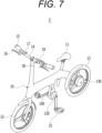
- FIG. 7 is a perspective view schematically illustrating an electric mobility according to another embodiment of the present disclosure.
- the electric mobility 1' may include a frame 10, a generator 120, a motor 130, and a controller 140.
- the generator 120 may comprise, for example, but not limited to, a power circuit for generating or providing power
- the controller 140 may comprise, for example, but not limited to, a processor or controller, or any suitable circuitry and/or electronic components, such as a microprocessor.
- a saddle 11 connected to the frame 10 may be provided for the user to board, and front and rear wheels 12 and 13 may be respectively provided at the front and rear parts of the frame 10.
- a configuration in which the motor 130 is provided on the rear wheel 13 is illustrated, but it is not limited thereto, and the motor 130 may be provided on at least one of the front wheel 12 or the rear wheel 13.
- Pedals 21 may be rotatably mounted on both sides of the generator 120, and the rotational force of the pedal 21 may be converted into electrical energy in the generator 120 and the electrical energy can be charged in a battery provided in the frame 10.
- a handlebar 14 for steering the electric mobility 1' may be provided at an upper part of the front part of the frame 10.
- the handlebar 14 may include handles 15 provided at ends of the handlebar 14, brakes 16 for decelerating or stopping the electric bicycle 1', and a throttle 17 for driving the motor 130.
- an interface (HMI) 18 may be installed at the handlebar 14, and a start button 19 may be provided on the interface 18.
- the start button 19 may be a touch-type button capable of being touched on a display.
- the start button 19 may be implemented as a mechanical push button.
- the controller 140 may determine whether the start button 19 is manipulated or operated in the stationary state. If it is determined that the start button 19 is manipulated or operated, the controller 140 may confirm that a user has intention to start the electric mobility and control the electric mobility to be in the standby state in which the electric mobility can be started.
- the controller 140 may control the electric mobility to be in the driving state in which the motor 130 is being driven.
- the controller 140 may control the electric mobility to be in the stationary state so that the electric mobility 1' cannot start.
- start button 19 may be installed on the interface 18 installed at a predetermined distance from the handle 15 on the handlebar 14. In this way, by installing the start button at the predetermined distance from the handlebar 14, it is possible to effectively prevent the user from accidentally operating the start button, and accordingly, it is possible to more reliably confirm the user's intention to start the electric mobility.
- an e-mobility such as an electric transport, an electric bicycle or an electric cargo (e-Cargo)
- an user's intention e.g. a driver's intention
Landscapes
- Engineering & Computer Science (AREA)
- Mechanical Engineering (AREA)
- Chemical & Material Sciences (AREA)
- Combustion & Propulsion (AREA)
- Transportation (AREA)
- Power Engineering (AREA)
- Electric Propulsion And Braking For Vehicles (AREA)
Abstract
A method and system for controlling an electric mobility are provided. The method and system may determine whether a brake is operated in a stationary state in which the electric mobility is stopped; convert the state of the electric mobility from the stationary state into a brake operation state if it is determined that the brake is operated in the stationary state; determine whether the brake is released in the brake operation state; and convert the state of the electric mobility from the brake operation state into a standby state in which the mobility can be started if it is determined that the brake is released in the brake operation state.
Description
- This application claims the benefit of and priority to
Korean Patent Application No. 2023-0042704 filed on March 31, 2023 - The present disclosure generally relates to a method and system for controlling or driving an electric mobility. More specifically, the present disclosure relates to a method and system for controlling or driving an electric mobility that can check or confirm user's intention to start the electric mobility and control the electric mobility to start only if the user has the intention to start the electric mobility.
- An electric mobility, such as an electric transport, an electric bicycle or an electric cargo (e-cargo), assists a person, or drives the electric mobility by driving a motor with electricity. A PAS (Pedal Assistance System) type method uses the power of a motor to assist a person stepping on a pedal to drive the wheels, and a throttle type method drives the wheels only with the power of the motor by pulling a handle. In addition, there is also a PAS/throttle type electric mobility that supports both the PAS type method and the throttle type method.
- According to some embodiments of the present disclosure, a driving control method of an electric mobility may comprise: a brake operation determination step of determining whether a brake is operated in a stationary state in which the electric mobility is stopped; a brake operation state conversion step of converting the electric mobility into a brake operation state if it is determined that the brake is operated in the brake operation determination step; a brake release determination step of determining whether the brake is released in the brake operation state; and a standby state conversion step of converting the electric mobility into a standby state in which the electric mobility can be started if it is determined that the brake is released in the brake release determination step.
- The driving control method may further comprise a stationary state conversion step of controlling the electric mobility to be converted into the stationary state if a predetermined time has elapsed without starting the electric mobility in the standby state.
- The driving control method may further comprise a driving state conversion step of converting the electric mobility into a driving state in which a motor is being driven if a pedal or a throttle mounted at the electric mobility is operated before a predetermined time elapses in the standby state.
- Further, if the brake is operated again in the standby state, the electric mobility may be converted into the brake operation state.
- Further, the predetermined time may be set within a range from 5 seconds to 10 seconds.
- Further, in the driving state, if the electric mobility is decelerated and the motor is stopped, the electric mobility may be converted into the standby state.
- Further, in the stationary state, the electric mobility may not be started even if the pedal or the throttle mounted at the electric mobility is operated.
- A driving control method of an electric mobility according to another embodiment of the present disclosure comprises: a start button operation determination step of determining whether a start button installed at the electric mobility is operated in a stationary state in which the electric mobility is stopped; and a standby state conversion step of converting the electric mobility into a standby state in which the electric mobility can be started if it is determined that the start button is operated in the start button operation determination step.
- Further, the start button may be located on an interface installed at the electric mobility.
- A driving system of an electric mobility according to embodiments of the present disclosure comprises: a generator configured to generate voltage by driving a pedal or operating a throttle; a motor mounted at at least one of front and rear wheels of the electric mobility to provide rotational force to a wheel; and a controller configured to control the driving system, wherein the controller comprises: a starting intention determination unit configured to determine a user's intention to start in a stationary state in which the electric mobility is stopped; and a standby state conversion unit configured to convert the electric mobility into a standby state in which the electric mobility can be started if it is determined that there is the user's intention to start in the starting intention determination unit.
- Further, the starting intention determination unit may determine whether a brake installed at the electric mobility is operated and then released, and determine that there is the user's intention to start if it is determined that the brake is released after being operated.
- Further, the starting intention determination unit may determine whether a start button installed at the electric mobility is operated, and determine that there is the user's intention to start if it is determined that the start button is operated.
- The control unit may further comprise a stationary state conversion unit configured to determine whether a predetermined time has elapsed without starting the electric mobility in the standby state, and to convert the electric mobility into the stationary state if the predetermined time has elapsed.
- The control unit may further comprise a driving state conversion unit configured to determine whether a pedal or a throttle mounted at the electric mobility has been operated before a predetermined time elapses in the standby state, and to convert the electric mobility into a driving state in which the motor is being driven if the pedal or the throttle has been operated.
- Further, the start button may be located on an interface installed at the electric mobility.
- The above-described means for solving the problem is only exemplary and should not be construed as limiting the present disclosure. In addition to the exemplary embodiments described above, additional embodiments may exist in the drawings and the following detailed description.
- According to certain embodiments of the present disclosure, it is possible to provide a method and system for controlling an electric mobility that enables safe driving by controlling the electric mobility to be started (e.g. initiate to drive a motor) only if the user has an intention to start the electric mobility.
- In addition, according to some embodiments of the present disclosure, it is possible to provide a method and system for controlling an electric mobility with improved safety by allowing the electric mobility to be started only if the user has an intention to start.
- However, the effects obtainable from the present disclosure are not limited to the effects described above, and other effects may exist.
-
-
FIG. 1 is a perspective view for schematically showing an electric mobility according to an embodiment of the present disclosure. -
FIG. 2 is a block diagram of a system for controlling an electric mobility according to an embodiment of the present disclosure. -
FIG. 3 is a flowchart for illustrating a method for controlling an electric mobility according to an embodiment of the present disclosure. -
FIG. 4A is a block diagram for schematically illustrating a system for an electric mobility according to an embodiment of the present disclosure, andFIG. 4B is a block diagram for illustrating in detail a system for controlling an electric mobility according to an embodiment of the present disclosure. -
FIG. 5 is a flowchart for illustrating a method for controlling an electric mobility according to another embodiment of the present disclosure. -
FIG. 6 is a block diagram for specifically illustrating a system for controlling an electric mobility according to another embodiment of the present disclosure. -
FIG. 7 is a perspective view for schematically illustrating an electric mobility according to another embodiment of the present disclosure. - Hereinafter, with reference to the accompanying drawings, embodiments of the present disclosure will be described in detail so that those skilled in the art can easily practice the embodiments. However, the present disclosure may be implemented in many different forms and is not limited to the embodiments described herein. In addition, in order to clearly describe the present disclosure in the drawings, parts irrelevant to the description are omitted, and similar reference numerals are attached to similar parts throughout the present disclosure.
- Throughout the present disclosure, if a part is said to be "connected" to another part, it is not only "directly connected", but also "electrically connected" with another element in between, including cases where they are "indirectly connected".
- Throughout the present disclosure, if one member is said to be located "on", "above", "under", or "below" the other member, this includes not only the case of being in contact with the other member, but also the case that another member is positioned between the two members.
- Throughout the present disclosure, if a part "includes" a certain component, it does not mean excluding other components, and it does mean that it may further include other components, unless otherwise stated.
- Various embodiments of the present disclosure generally relate to a driving control method of an electric mobility and a driving system of the electric mobility.
-
FIG. 1 is a perspective view for schematically illustrating an electric mobility according to an embodiment of the present disclosure. - An
electric bicycle 1 shown inFIG. 1 as an example of an electric mobility may include aframe 10, agenerator 20, amotor 30, and acontroller 40. - In addition, a
saddle 11 connected to theframe 10 may be provided for a user to board, and front andrear wheels frame 10. Themotor 30 may be provided on at least one of thefront wheel 12 and therear wheel 13, and in the example ofFIG. 1 , a configuration that themotor 30 provided on therear wheel 13 provides rotational force to therear wheel 13 is disclosed. - Pedals 21 are rotatably installed at both sides of the
generator 20, and the rotational force of thepedal 21 may be converted into electrical energy in thegenerator 20 and the electrical energy may be charged in a battery provided in theframe 10. - In addition, a
handlebar 14 for steering theelectric bicycle 1 is provided at an upper and front part of theframe 10. Further,handles 15 provided at ends of thehandlebar 14,brakes 16 for decelerating or stopping theelectric bicycle 1 and athrottle 17 for driving themotor 30 may be provided. -
FIG. 2 is a block diagram for illustrating a system for controlling an electric mobility according to an embodiment of the present disclosure. The system may include, for example, agenerator 20, amotor 30, acontroller 40, apedal sensor unit 50, athrottle sensor unit 60, and amotor sensor unit 70. - The
pedal sensor unit 50 may be configured to detect the position and/or speed of thepedal 21, thethrottle sensor unit 60 detects the manipulation or operation of thethrottle 17, and themotor sensor unit 70 detects the position and/or speed of themotor 30. Based on the detection of thepedal sensor unit 50, thethrottle sensor unit 60, and themotor sensor unit 70, thecontroller 40 may be configured to control the load of thegenerator 20 and the speed of themotor 30. - On the other hand, if the user is around the electric bicycle in a stationary state in which the motor of the
electric bicycle 1 cannot be actuated or driven, or if the user accidentally moves thepedal 21 or thethrottle 17, since the load of thegenerator 20 and the speed of themotor 30 are controlled based on the movement of thepedal 21 or thethrottle 17, theelectric bicycle 1 may be started in a situation where the user has no intention of starting theelectric bicycle 1. - In this case, there may be a risk of injury to the user of the
electric bicycle 1, and a collision with another person may also occur. In this respect, in using an electric mobility such as theelectric bicycle 1, there may be a need for controlling the electric mobility to be started only when the user has the intention to start the electric mobility in order to ensure the safety. - Some embodiments or the present disclosure may solve the above-mentioned problems by providing a method and system for controlling an electric mobility that can be started only in a safe situation that a user has intention to start the electric mobility by checking the user's intention to start the electric mobility.
-
FIG. 3 is a flowchart illustrating a method for controlling an electric mobility according to an embodiment of the present disclosure. - Referring to
FIG. 3 , the method for controlling the electric mobility according to the embodiment of the present disclosure may include a brake operation determination step S200 of determining whether a brake of the electric mobility is operated in a stationary state S100 in which the electric mobility is stopped. - The stationary state S100 may be, for example, but not limited to, a state in which a motor of the electric mobility is not driven, and in this stationary state, the electric mobility (drive motor) cannot be started or initiated even if a pedal or a throttle is moved.
- Meanwhile, in the present disclosure, "start" may mean start of driving or actuating the motor of the electric mobility. Therefore, if a user manually drags and moves an electric bicycle, although the wheels may rotate and the electric bicycle may move, since the motor is not being driven, it is not regarded as 'start' but regarded as the 'stationary state'.
- If it is determined that the brake is applied or operated in the brake operation determination step S200 ('YES' in step S200), a brake operation state conversion step S300 of converting the state of the electric mobility into the brake operation state (a brake ON state) may be performed.
- Subsequently, a brake release determination step S400 of determining whether the user has released the brake while the brake is operating may be performed.
- If it is determined that the brake is released in the brake release determination step S400 ('YES' in S400), a standby state conversion step S500 of converting the state of the electric mobility into the standby state in which the electric mobility can be started may be performed.
- In the standby state, the electric mobility can be started by operating the pedal or the throttle. At step S600, it is determined whether the electric mobility in the standby state is started by operating the pedal or the throttle mounted or included at the electric mobility before a predetermined time elapses. If the electric mobility is started before the predetermined time elapses ('YES in step S600'), the state of the electric mobility is converted into a driving state S700 in which the motor is being driven or actuated.
- However, if the predetermined time has elapsed without starting the electric mobility in the standby state ('NO' in step S600), the state of the electric mobility may be controlled to return to the stationary state S100 in which the electric mobility cannot be started. This is to prevent the electric mobility from starting unintentionally in a situation where the time has passed after the brake is operated and then released, or the intention to start the electric mobility does not exist anymore.
- Here, the predetermined time at step S600 may be set to be within a range of, for example, but not limited to, from about 5 seconds to about 10 seconds. If the predetermined time is set to be too short, it may cause inconvenience to the user, and if the predetermined time at step S600 is set to be too long, the possibility of accidentally operating the pedal or the throttle in a state where there is no intention to start the electric mobility may increase. Therefore, it is preferable to set the time to about 5 seconds or more and about 10 seconds or less.
- On the other hand, if the brake is operated in the standby state, the state of the electric mobility may be converted into the brake ON state, and then if the brake is released, the state of the electric mobility may be converted into the standby state again.
- Since the predetermined time is compared with time elapsed from when the brake is released so that the state of the electric mobility is converted into the standby state, the standby state may be maintained by repeating the apply and release of the brake.
- On the other hand, since the motor of the electric mobility is being actuated or driven in the driving state initiated or converted by operating the pedal or the throttle in the standby state, the electric mobility may be accelerated or decelerated by manipulating or accelerating the pedal or operating the brake.
- A step S800, it is determined whether the motor of the electric mobility is stopped after decelerating the electric mobility by the operation of the brake, and if it is determined that the motor is stopped ('YES' in step S800), the state of the electric mobility may be converted into the standby state.
- Because the standby state is a state in which the electric mobility can be started, the motor of the electric mobility can be driven again if the user operates the pedal or the throttle within the predetermined time. However, the electric mobility may return to the stationary state as described above if the predetermined time elapses.
- The method for controlling the electric mobility as described above can clearly confirm whether a user (e.g. a driver) has the intention to start the electric mobility by operating and releasing the brake, and may convert the state of the electric mobility into the standby state in which the motor can be driven only if the user has the intention to start the electric mobility. Accordingly, a remarkable effect can be accomplished in that safe use of the mobility becomes possible.
-
FIG. 4A is a block diagram for schematically illustrating a system of controlling an electric mobility according to an embodiment of the present disclosure, andFIG. 4B is a block diagram for illustrating in detail a system of controlling an electric mobility according to an embodiment of the present disclosure. - Referring to
FIG. 4A , asystem 100 for driving or controlling the electric mobility according to the embodiment of the present disclosure may include agenerator 120 configured to generate voltage in response to the user's manipulation or operation of a pedal or a throttle, amotor 130 configured to be driven by a current applied thereto, and acontroller 140 configured to control thesystem 100. - Here, the
controller 140 may include a startingintention determination unit 141 configured to determine the user's intention to start the electric mobility, a standbystate conversion unit 142 configured to convert the state of the electric mobility into the standby state, a stationarystate conversion unit 143 configured to convert the state of the electric mobility into the stationary state, and a drivingstate conversion unit 144 configured to convert the state of the electric mobility into the driving state in which the motor of the electric mobility is being driven. - According to an embodiment of the present disclosure, by converting the state of the electric mobility into the standby state in which the start of the electric mobility can be performed in the standby
state conversion unit 142 after determining and confirming the user's intention to start the electric mobility in the startingintention determination unit 141, thesystem 100 may allow the electric mobility to be started only if the user has the intention to start the electric mobility. - In addition, it may be determined whether a predetermined time has elapsed without starting the electric mobility in the standby state. If the predetermined time has elapsed without starting the electric mobility in the standby state, the stationary
state conversion unit 143 may convert the state of the electric mobility into the stationary state. Further, if the pedal or the throttle is operated or manipulated before the predetermined time elapses, the drivingstate conversion unit 144 may convert the state of the electric mobility into the driving state. Accordingly, thesystem 100 can effectively change the state of the electric mobility even if the user's intention to start the electric mobility is changed in the standby state. - Referring to
FIG. 4B in more detail, a system for controlling an electric mobility according to an embodiment of the present disclosure may include apedal sensor unit 150 configured to detect the position and/or speed of the pedal, athrottle sensor unit 160 configured to detect the operation of the throttle, amotor sensor unit 170 configured to detect the position and/or speed of the motor, and abrake sensor unit 180 configured to detect the apply or operation and the release of the brake. - In this regard, since only one of the pedal and the throttle may be provided depending on the electric mobility, the system for controlling the electric mobility according to an embodiment of the present disclosure may include either of the
pedal sensor unit 150 and thethrottle sensor unit 160. - On the other hand, as described above, if the electric mobility is in the stationary state, the system can be set such that the electric mobility cannot be started (e.g. the motor of the electric mobility cannot be driven) even if the pedal or the throttle is manipulated or operated.
- If the user operates the brake to enter the brake ON state and then releases the brake, the
controller 140 may receive the brake operation signal and then receive the brake release signal from thebrake sensor unit 180, and the startingintention determination unit 141 may determine that the user has intention to start the electric mobility. - On the other hand, if it is determined that the user has the intention to start the electric mobility in the starting
intention determination unit 141, the standbystate conversion unit 142 may convert the state of the electric mobility into the standby state. Then, if the operation signal of the pedal or the throttle is received from thepedal sensor unit 150 or thethrottle sensor unit 160 within the predetermined time, the drivingstate conversion unit 144 may determine the operation of the pedal or the throttle and convert the state of the electric mobility into the driving state in which the motor of the electric mobility is being driven. - On the other hand, if the operation signal of the pedal or the throttle is not received within the predetermined time, the stationary
state conversion unit 143 may convert the state of the electric mobility back to the stationary state. - According to this configuration, the electric mobility can be driven only if the
brake sensor unit 180 receives signals of applying/operating and releasing the brake, and thus, the motor of the electric mobility can be driven after confirming the user's intention to start the electric mobility. Accordingly, it is possible to prevent dangerous situations from occurring. -
FIG. 5 is a flowchart illustrating a method for controlling an electric mobility according to another embodiment of the present disclosure. - Referring to
FIG. 5 , the method for controlling the electric mobility according to another embodiment of the present disclosure may include a start button operation determination step S210 of determining whether a start button installed at the electric mobility is operated or not in the stationary state S110 in which the electric mobility cannot be started. - In the stationary state S110 in which the electric mobility cannot be started, the motor of the electric mobility cannot be driven even if the pedal or the throttle is operated.
- Thereafter, it is determined whether the start button is manipulated or operated in the start button operation determination step S210. If it is determined that the start button is manipulated or operated ('YES' in S210), a standby state conversion step S310 in which the state of the electric mobility is converted into the standby state in which the electric mobility can be started is performed.
- In this standby state, the electric mobility can be started by operating the pedal or the throttle. That is, at step S410, it is determined whether the electric mobility is started by operating the pedal or the throttle mounted at the electric mobility before the elapse of the predetermined time in the standby state S310 . If the electric mobility is started before the elapse of the predetermined time ('YES' in S410), the state of the electric mobility may be converted into the driving state S510 in which the motor of the electric mobility is being driven.
- However, if the predetermined time has elapsed without starting the electric mobility in the standby state ('NO' in S410), the electric mobility can be controlled to return to the stationary state S110 in which the electric mobility cannot be started. This is for controlling the electric mobility to return to the stationary state after the predetermined time has elapsed, in order to prevent the electric mobility from starting unintentionally in a situation where a certain time has passed after the start button is manipulated or operated and the user has no intention to start the electric mobility any more.
- The predetermined time may be set within a range of from about 5 seconds to about 10 seconds, although not required.
- On the other hand, if the start button is manipulated or operated again in the standby state, it is determined whether the predetermined time has elapsed from the time that the start button was operated. Accordingly, the standby state may be continuously maintained by repeatedly operating the start button.
- Since the motor of the electric mobility is being actuated or driven in the driving state initiated or converted by operating the pedal or the throttle in the standby state, the electric mobility can be accelerated or decelerated by manipulating or accelerating the pedal or operating the brake.
- At step S610, it is determined whether the motor of the electric mobility is stopped by decelerating the electric mobility or operating or applying the brake. If the motor of the electric mobility is stopped ('YES' in S610), the state of the electric mobility may be converted into the standby state.
- Since the standby state is a state in which the electric mobility can be started, if the user operates the pedal or the throttle within the predetermined time, the motor of the electric mobility can be driven again. However, if the predetermined time has elapsed without operating the pedal or the throttle, the electric mobility returns to the stationary state as described above.
- According to another embodiment of the present disclosure, the state of the electric mobility can be converted into the standby state by the operation of the start button instead of operating and releasing the brake. Accordingly, the state the electric mobility can be converted into a state in which the electric mobility can be started by checking or confirming the user's intention to start the electric mobility in a simpler way.
- In addition, by locating the start button at a location where it is difficult for the user to manipulate or operate it by mistake (for example, on an interface (Human Machine Interface; HMI) installed at the electric mobility), the user's intention to start the electric mobility can be more reliably confirmed. Accordingly, the possibility of occurrence of dangerous situations may be further reduced.
-
FIG. 6 is a block diagram for illustrating a system for controlling an electric mobility according to another embodiment of the present disclosure. - The system for controlling the electric mobility according to another embodiment of the present disclosure may include a
generator 120 configured to generate voltage in response to the manipulation or operation of a pedal or a throttle, amotor 130 configured to be driven by current applied thereto, and acontroller 140 configured to control the system. - Here, the
controller 140 may include a startingintention determination unit 141 configured to determine the user's intention to start the electric mobility, a standbystate conversion unit 142 configured to convert the state of the electric mobility into the standby state, a stationarystate conversion unit 143 configured to convert the state of the electric mobility into the stationary state, and a drivingstate conversion unit 144 configured to convert the state of the electric mobility into the driving state in which the motor of the electric mobility is being driven. - In addition, the system controlling the electric mobility according to another embodiment of the present disclosure may include a
pedal sensor unit 150 configured to detect the position and/or speed of the pedal, athrottle sensor unit 160 configured to detect the operation of the throttle, amotor sensor unit 170 configured to detect the position and/or speed of the motor, abrake sensor unit 180 configured to detect the apply or operation, or release of the brake, and a startbutton sensor unit 190 configured to detect the manipulation or operation of the start button. - As described above, since some electric mobilities may include either one of the pedal and the throttle, the driving system of the present disclosure may include either one of the
pedal sensor unit 150 and thethrottle sensor unit 160. - If the start button is manipulated or operated in a stationary state in which the electric mobility cannot be started, the
controller 140 may receive a start button operation signal from the startbutton sensor unit 190, and in response to the button operation signal, the startingintention determination unit 141 may determine whether a user has intention to start the electric mobility. - On the other hand, if it is determined that the user has the intention to start the electric mobility in the staring
intention determination unit 141, the standbystate conversion unit 142 may convert the state of the electric mobility into the standby state. Then, if an operation signal of the pedal or the throttle is received from thepedal sensor unit 150 or thethrottle sensor unit 160 within the predetermined time, the drivingstate conversion unit 144 may determine that the pedal or the throttle is manipulated or operated and convert the state of the electric mobility into the driving state in which the motor of the electric mobility is being driven. - On the other hand, if the operation signal of the pedal or the throttle is not received within the predetermined time, the stationary
state conversion unit 143 may convert the state of the electric mobility into the stationary state. - According to this configuration, by enabling to drive the electric mobility only if the start button operation signal is received from the start
button sensor unit 190, so that the motor of the electric mobility can be actuated or driven after confirming the user's intention, it is possible to effectively prevent the dangerous situations from occurring. -
FIG. 7 is a perspective view schematically illustrating an electric mobility according to another embodiment of the present disclosure. - Referring to
FIG. 7 , the electric mobility 1' according to another embodiment of the present disclosure may include aframe 10, agenerator 120, amotor 130, and acontroller 140. Thegenerator 120 may comprise, for example, but not limited to, a power circuit for generating or providing power, and thecontroller 140 may comprise, for example, but not limited to, a processor or controller, or any suitable circuitry and/or electronic components, such as a microprocessor. - In addition, a
saddle 11 connected to theframe 10 may be provided for the user to board, and front andrear wheels frame 10. In the exemplary embodiment of the present disclosure ofFIG. 7 , a configuration in which themotor 130 is provided on therear wheel 13 is illustrated, but it is not limited thereto, and themotor 130 may be provided on at least one of thefront wheel 12 or therear wheel 13. -
Pedals 21 may be rotatably mounted on both sides of thegenerator 120, and the rotational force of the pedal 21 may be converted into electrical energy in thegenerator 120 and the electrical energy can be charged in a battery provided in theframe 10. - In addition, a
handlebar 14 for steering the electric mobility 1' may be provided at an upper part of the front part of theframe 10. Thehandlebar 14 may includehandles 15 provided at ends of thehandlebar 14,brakes 16 for decelerating or stopping the electric bicycle 1', and athrottle 17 for driving themotor 130. - Meanwhile, an interface (HMI) 18 may be installed at the
handlebar 14, and astart button 19 may be provided on theinterface 18. Specifically, thestart button 19 may be a touch-type button capable of being touched on a display. However, thestart button 19 may be implemented as a mechanical push button. - The
controller 140 may determine whether thestart button 19 is manipulated or operated in the stationary state. If it is determined that thestart button 19 is manipulated or operated, thecontroller 140 may confirm that a user has intention to start the electric mobility and control the electric mobility to be in the standby state in which the electric mobility can be started. - In addition, if the
controller 140 determines that the pedal 21 or thethrottle 17 has been manipulated or operated within the predetermined time (e.g., from 5 to 10 seconds) in the standby state, the controller may control the electric mobility to be in the driving state in which themotor 130 is being driven. - On the other hand, if the pedal or the throttle is not manipulated or operated within the predetermined time, the
controller 140 may control the electric mobility to be in the stationary state so that the electric mobility 1' cannot start. - In addition, the
start button 19 may be installed on theinterface 18 installed at a predetermined distance from thehandle 15 on thehandlebar 14. In this way, by installing the start button at the predetermined distance from thehandlebar 14, it is possible to effectively prevent the user from accidentally operating the start button, and accordingly, it is possible to more reliably confirm the user's intention to start the electric mobility. - According to some embodiments of the present disclosure, in an e-mobility such as an electric transport, an electric bicycle or an electric cargo (e-Cargo), by checking an user's intention (e.g. a driver's intention) to start the electric mobility once again by determining whether the brake is operated and then released or whether the start button is operated, it is possible to provide a method and a system that can prevent unintentional start of the electric mobility and enable safe departure.
- In addition, according to certain embodiments of the present disclosure, by determining whether the pedal or the throttle is manipulated or operated within a predetermined time in a standby state in which the electric mobility can be started and by converting the state of the electric mobility into a driving state or a stationary state based on the determination result, it is possible to provide a method and a system that can improve the user's safety and convenience at the same time.
- The above description of the present disclosure is for illustrative purposes, and those skilled in the art may understand that it can be easily modified into other specific forms without changing the technical spirit or essential features of the present disclosure. Therefore, the embodiments described above should be understood as illustrative in all respects and not limiting. For example, each component described as a single type may be implemented in a distributed manner, and similarly, components described as distributed may be implemented in a combined form.
- The scope of the present disclosure is indicated by the following claims rather than the above detailed description, and all changes or modifications derived from the meaning and scope of the claims and equivalent concepts should be interpreted to be included in the scope of the present disclosure.
-
- 100: Driving system
- 120: Generator
- 130: Motor
- 140: Controller
- 141: Starting intention determination unit
- 142: Standby state conversion unit
- 143: Stationary state conversion unit
- 144: Driving state conversion unit
- 150: Pedal sensor unit
- 160: Throttle sensor unit
- 170: Motor sensor unit
- 180: Brake sensor unit
- 190: Start button sensor unit
Claims (15)
- A method for controlling an electric mobility, the method comprising:determining whether a brake is operated in a stationary state in which the electric mobility is prevented from being started;if it is determined that the brake is operated in the stationary state, converting a state of the electric mobility from the stationary state into a brake operation state in which the brake is operated;determining whether the brake is released in the brake operation state in which the brake is operated; andif it is determined that the brake is released in the brake operation state in which the brake is operated, converting the state of the electric mobility from the brake operation state into a standby state in which the electric mobility is allowed to be started.
- The method of claim 1, further comprising if a predetermined time has elapsed without starting the electric mobility in the standby state in which the electric mobility is allowed to be started, controlling the electric mobility to be converted from the standby state, in which the electric mobility is allowed to be started, into the stationary state, in which the electric mobility is prevented from being started.
- The method of claim 1, further comprising, if a pedal or a throttle included in the electric mobility is operated before a predetermined time elapses in the standby state, converting the state of the electric mobility from the standby state, in which the electric mobility is allowed to be started, into a driving state, in which a motor comprised in the electric mobility is being driven.
- The method of claim 1, further comprising, if the brake is operated in the standby state in which the electric mobility is allowed to be started, converting the state of the electric mobility from the standby state into the brake operation state in which the brake is operated.
- The method of claim 2 or claim 3, wherein the predetermined time is set within a range from 5 seconds to 10 seconds.
- The method of claim 3, further comprising, if the electric mobility is decelerated and the motor comprised in the electric mobility is stopped in the driving state in which the motor is driven, converting the state of the electric mobility from the driving state, in which the motor is driven, into the standby state, in which the electric mobility is allowed to be started.
- The method of any one of claims 1 to 4, wherein, in the stationary state, the electric mobility is not started even if a pedal or a throttle included in the electric mobility is operated.
- A method for controlling an electric mobility, the method comprising:determining whether a start button associated with the electric mobility is operated in a stationary state in which the electric mobility is prevented from being started; andif it is determined that the start button is operated in the stationary state, converting the state of the electric mobility from the stationary state, in which the electric mobility is prevented from being started, into a standby state in which the electric mobility is allowed to be started.
- The method of claim 8, further comprising, if a predetermined time has elapsed without starting the electric mobility in the standby state in which the electric mobility is allowed to be started, converting the state of the electric mobility from the standby state, in which the electric mobility is allowed to be started, into the stationary state, in which the electric mobility is prevented from being started.
- The method of claim 8, further comprising, if a pedal or a throttle included in the electric mobility is operated before a predetermined time elapses in the standby state in which the electric mobility is allowed to be started, converting the state of the electric mobility from the standby state, in which the electric mobility is allowed to be started, into a driving state, in which a motor comprised in the electric mobility is being driven.
- The method of claim 9 or claim 10, wherein the predetermined time is set within a range from 5 seconds to 10 seconds.
- The method of claim 10, further comprising, if the electric mobility is decelerated and the motor included in the electric mobility is stopped in the driving state in which the motor is driven, converting the state of the electric mobility from the driving state, in which the motor is driven, into the standby state, in which the electric mobility is allowed to be started.
- The method of any one of claims 8 to 10, wherein, in the stationary state, the electric mobility is not started even if a pedal or a throttle included in the electric mobility is operated.
- The method of any one of claims 8 to 10, wherein the start button is provided on a user interface associated with the electric mobility.
- A system for controlling an electric mobility, the system comprising:a generator configured to generate voltage in response to operation of a pedal or a throttle;a motor operably connected to at least one of wheels of the electric mobility; anda controller configured to:determine whether a user has intention to start the electric mobility in a stationary state in which the electric mobility is prevented to be started, andif it is determined that the user has the intention to start the electric mobility in the stationary state, convert a state of the electric mobility from the stationary state, in which the electric mobility is prevented to be started, into a standby state, in which the electric mobility is allowed to be started.
Applications Claiming Priority (1)
| Application Number | Priority Date | Filing Date | Title |
|---|---|---|---|
| KR1020230042704A KR20240147154A (en) | 2023-03-31 | 2023-03-31 | Driving control method and driving system of electric mobility |
Publications (1)
| Publication Number | Publication Date |
|---|---|
| EP4438384A1 true EP4438384A1 (en) | 2024-10-02 |
Family
ID=87377821
Family Applications (1)
| Application Number | Title | Priority Date | Filing Date |
|---|---|---|---|
| EP23185909.1A Pending EP4438384A1 (en) | 2023-03-31 | 2023-07-17 | Method and system for controlling electric mobility |
Country Status (3)
| Country | Link |
|---|---|
| US (1) | US12466516B2 (en) |
| EP (1) | EP4438384A1 (en) |
| KR (1) | KR20240147154A (en) |
Citations (2)
| Publication number | Priority date | Publication date | Assignee | Title |
|---|---|---|---|---|
| US20130274983A1 (en) * | 2010-12-28 | 2013-10-17 | Kawasaki Jukogyo Kabushiki Kaisha | Acceleration Control System in Electric Vehicle |
| CN203438868U (en) * | 2013-05-17 | 2014-02-19 | 游仁贵 | Control device for preventing accidental motor start during push travel of electric bicycle |
Family Cites Families (7)
| Publication number | Priority date | Publication date | Assignee | Title |
|---|---|---|---|---|
| JP2000050418A (en) | 1998-07-24 | 2000-02-18 | Yamaha Motor Co Ltd | Self-propelled electric bicycle |
| JP6885843B2 (en) | 2017-10-24 | 2021-06-16 | 株式会社シマノ | Brake system |
| KR102884624B1 (en) * | 2020-06-23 | 2025-11-11 | 현대자동차주식회사 | Method for controlling manual drive mode of autonomous driving vehicle with foldable pedal apparatus |
| JP7530576B2 (en) * | 2021-01-28 | 2024-08-08 | スズキ株式会社 | Small electric vehicle |
| KR20220140085A (en) * | 2021-04-08 | 2022-10-18 | 현대자동차주식회사 | Operation control method of foldable pedal apparatus |
| JP7767207B2 (en) * | 2022-03-29 | 2025-11-11 | 本田技研工業株式会社 | Motorcycle driving assistance system |
| KR20230151591A (en) * | 2022-04-25 | 2023-11-02 | 현대자동차주식회사 | Power management device and vehicle |
-
2023
- 2023-03-31 KR KR1020230042704A patent/KR20240147154A/en active Pending
- 2023-07-07 US US18/219,567 patent/US12466516B2/en active Active
- 2023-07-17 EP EP23185909.1A patent/EP4438384A1/en active Pending
Patent Citations (2)
| Publication number | Priority date | Publication date | Assignee | Title |
|---|---|---|---|---|
| US20130274983A1 (en) * | 2010-12-28 | 2013-10-17 | Kawasaki Jukogyo Kabushiki Kaisha | Acceleration Control System in Electric Vehicle |
| CN203438868U (en) * | 2013-05-17 | 2014-02-19 | 游仁贵 | Control device for preventing accidental motor start during push travel of electric bicycle |
Non-Patent Citations (1)
| Title |
|---|
| APACHE: "USER MANUAL FOR E-BIKES", 20 August 2020 (2020-08-20), XP093112801, Retrieved from the Internet <URL:https://greatebike.eu/uploads/assets/files/AP-User-Manual-eBikes-EN-2021-Web.pdf> [retrieved on 20231215] * |
Also Published As
| Publication number | Publication date |
|---|---|
| US20240326951A1 (en) | 2024-10-03 |
| US12466516B2 (en) | 2025-11-11 |
| KR20240147154A (en) | 2024-10-08 |
Similar Documents
| Publication | Publication Date | Title |
|---|---|---|
| US9121487B2 (en) | Pilot interface for aircraft electric taxi system | |
| KR101081863B1 (en) | Narrow space slow moving operational device for vehicle and operation method thereof | |
| CN112740893A (en) | Riding type mower | |
| JP2014221086A (en) | Walking assist vehicle | |
| EP4438384A1 (en) | Method and system for controlling electric mobility | |
| JP2011031706A (en) | Traveling vehicle with assist motor | |
| JPH07215263A (en) | Electric bicycle | |
| JPH10324290A (en) | Electric bicycle | |
| JPH10167161A (en) | Electric bicycle | |
| JPH0787623A (en) | Electric vehicle control device | |
| JP2001025101A (en) | Safety controller of electric vehicle | |
| JP2004142703A (en) | Electric assist bicycle | |
| KR102491668B1 (en) | Control method for personal mobility by using multi-function pedal | |
| JP2514617Y2 (en) | Battery car travel controller | |
| JP3756070B2 (en) | Forklift brake device | |
| US12304443B2 (en) | Driving assistance device | |
| JP6219736B2 (en) | Operation device for vehicles for disabled and healthy people | |
| JPH10164705A (en) | Small electric car | |
| JPH09284917A (en) | Drive control device for electric vehicle | |
| JPH10234786A (en) | Electric wheelchair | |
| JP7770169B2 (en) | Control device for electrically assisted vehicle and electrically assisted vehicle | |
| JP2007069778A (en) | Controller of operating device and controlling method | |
| JP3289029B2 (en) | Forklift travel prohibition control | |
| KR20040107680A (en) | parking brake control apparatus | |
| JPH07172799A (en) | Reach operation regulator of reach fork-lift truck |
Legal Events
| Date | Code | Title | Description |
|---|---|---|---|
| PUAI | Public reference made under article 153(3) epc to a published international application that has entered the european phase |
Free format text: ORIGINAL CODE: 0009012 |
|
| STAA | Information on the status of an ep patent application or granted ep patent |
Free format text: STATUS: REQUEST FOR EXAMINATION WAS MADE |
|
| 17P | Request for examination filed |
Effective date: 20230717 |
|
| AK | Designated contracting states |
Kind code of ref document: A1 Designated state(s): AL AT BE BG CH CY CZ DE DK EE ES FI FR GB GR HR HU IE IS IT LI LT LU LV MC ME MK MT NL NO PL PT RO RS SE SI SK SM TR |