EP4438369A1 - Motor vehicle with an improved arrangement of fuel tanks - Google Patents
Motor vehicle with an improved arrangement of fuel tanks Download PDFInfo
- Publication number
- EP4438369A1 EP4438369A1 EP24165416.9A EP24165416A EP4438369A1 EP 4438369 A1 EP4438369 A1 EP 4438369A1 EP 24165416 A EP24165416 A EP 24165416A EP 4438369 A1 EP4438369 A1 EP 4438369A1
- Authority
- EP
- European Patent Office
- Prior art keywords
- motor vehicle
- tank
- internal combustion
- combustion engine
- axis
- Prior art date
- Legal status (The legal status is an assumption and is not a legal conclusion. Google has not performed a legal analysis and makes no representation as to the accuracy of the status listed.)
- Granted
Links
Images





Classifications
-
- B—PERFORMING OPERATIONS; TRANSPORTING
- B60—VEHICLES IN GENERAL
- B60K—ARRANGEMENT OR MOUNTING OF PROPULSION UNITS OR OF TRANSMISSIONS IN VEHICLES; ARRANGEMENT OR MOUNTING OF PLURAL DIVERSE PRIME-MOVERS IN VEHICLES; AUXILIARY DRIVES FOR VEHICLES; INSTRUMENTATION OR DASHBOARDS FOR VEHICLES; ARRANGEMENTS IN CONNECTION WITH COOLING, AIR INTAKE, GAS EXHAUST OR FUEL SUPPLY OF PROPULSION UNITS IN VEHICLES
- B60K15/00—Arrangement in connection with fuel supply of combustion engines or other fuel consuming energy converters, e.g. fuel cells; Mounting or construction of fuel tanks
- B60K15/03—Fuel tanks
- B60K15/063—Arrangement of tanks
-
- B—PERFORMING OPERATIONS; TRANSPORTING
- B60—VEHICLES IN GENERAL
- B60K—ARRANGEMENT OR MOUNTING OF PROPULSION UNITS OR OF TRANSMISSIONS IN VEHICLES; ARRANGEMENT OR MOUNTING OF PLURAL DIVERSE PRIME-MOVERS IN VEHICLES; AUXILIARY DRIVES FOR VEHICLES; INSTRUMENTATION OR DASHBOARDS FOR VEHICLES; ARRANGEMENTS IN CONNECTION WITH COOLING, AIR INTAKE, GAS EXHAUST OR FUEL SUPPLY OF PROPULSION UNITS IN VEHICLES
- B60K13/00—Arrangement in connection with combustion air intake or gas exhaust of propulsion units
- B60K13/04—Arrangement in connection with combustion air intake or gas exhaust of propulsion units concerning exhaust
-
- B—PERFORMING OPERATIONS; TRANSPORTING
- B60—VEHICLES IN GENERAL
- B60K—ARRANGEMENT OR MOUNTING OF PROPULSION UNITS OR OF TRANSMISSIONS IN VEHICLES; ARRANGEMENT OR MOUNTING OF PLURAL DIVERSE PRIME-MOVERS IN VEHICLES; AUXILIARY DRIVES FOR VEHICLES; INSTRUMENTATION OR DASHBOARDS FOR VEHICLES; ARRANGEMENTS IN CONNECTION WITH COOLING, AIR INTAKE, GAS EXHAUST OR FUEL SUPPLY OF PROPULSION UNITS IN VEHICLES
- B60K15/00—Arrangement in connection with fuel supply of combustion engines or other fuel consuming energy converters, e.g. fuel cells; Mounting or construction of fuel tanks
- B60K15/03—Fuel tanks
- B60K15/073—Tank construction specially adapted to the vehicle
-
- B—PERFORMING OPERATIONS; TRANSPORTING
- B60—VEHICLES IN GENERAL
- B60K—ARRANGEMENT OR MOUNTING OF PROPULSION UNITS OR OF TRANSMISSIONS IN VEHICLES; ARRANGEMENT OR MOUNTING OF PLURAL DIVERSE PRIME-MOVERS IN VEHICLES; AUXILIARY DRIVES FOR VEHICLES; INSTRUMENTATION OR DASHBOARDS FOR VEHICLES; ARRANGEMENTS IN CONNECTION WITH COOLING, AIR INTAKE, GAS EXHAUST OR FUEL SUPPLY OF PROPULSION UNITS IN VEHICLES
- B60K5/00—Arrangement or mounting of internal-combustion or jet-propulsion units
- B60K5/04—Arrangement or mounting of internal-combustion or jet-propulsion units with the engine main axis, e.g. crankshaft axis, transversely to the longitudinal centre line of the vehicle
-
- F—MECHANICAL ENGINEERING; LIGHTING; HEATING; WEAPONS; BLASTING
- F02—COMBUSTION ENGINES; HOT-GAS OR COMBUSTION-PRODUCT ENGINE PLANTS
- F02M—SUPPLYING COMBUSTION ENGINES IN GENERAL WITH COMBUSTIBLE MIXTURES OR CONSTITUENTS THEREOF
- F02M37/00—Apparatus or systems for feeding liquid fuel from storage containers to carburettors or fuel-injection apparatus; Arrangements for purifying liquid fuel specially adapted for, or arranged on, internal-combustion engines
- F02M37/0076—Details of the fuel feeding system related to the fuel tank
- F02M37/0088—Multiple separate fuel tanks or tanks being at least partially partitioned
-
- B—PERFORMING OPERATIONS; TRANSPORTING
- B60—VEHICLES IN GENERAL
- B60K—ARRANGEMENT OR MOUNTING OF PROPULSION UNITS OR OF TRANSMISSIONS IN VEHICLES; ARRANGEMENT OR MOUNTING OF PLURAL DIVERSE PRIME-MOVERS IN VEHICLES; AUXILIARY DRIVES FOR VEHICLES; INSTRUMENTATION OR DASHBOARDS FOR VEHICLES; ARRANGEMENTS IN CONNECTION WITH COOLING, AIR INTAKE, GAS EXHAUST OR FUEL SUPPLY OF PROPULSION UNITS IN VEHICLES
- B60K5/00—Arrangement or mounting of internal-combustion or jet-propulsion units
- B60K2005/003—Arrangement or mounting of internal-combustion or jet-propulsion units the internal combustion or jet propulsion unit is arranged between the front and the rear axle
-
- B—PERFORMING OPERATIONS; TRANSPORTING
- B60—VEHICLES IN GENERAL
- B60K—ARRANGEMENT OR MOUNTING OF PROPULSION UNITS OR OF TRANSMISSIONS IN VEHICLES; ARRANGEMENT OR MOUNTING OF PLURAL DIVERSE PRIME-MOVERS IN VEHICLES; AUXILIARY DRIVES FOR VEHICLES; INSTRUMENTATION OR DASHBOARDS FOR VEHICLES; ARRANGEMENTS IN CONNECTION WITH COOLING, AIR INTAKE, GAS EXHAUST OR FUEL SUPPLY OF PROPULSION UNITS IN VEHICLES
- B60K15/00—Arrangement in connection with fuel supply of combustion engines or other fuel consuming energy converters, e.g. fuel cells; Mounting or construction of fuel tanks
- B60K15/03—Fuel tanks
- B60K2015/03118—Multiple tanks, i.e. two or more separate tanks
-
- B—PERFORMING OPERATIONS; TRANSPORTING
- B60—VEHICLES IN GENERAL
- B60K—ARRANGEMENT OR MOUNTING OF PROPULSION UNITS OR OF TRANSMISSIONS IN VEHICLES; ARRANGEMENT OR MOUNTING OF PLURAL DIVERSE PRIME-MOVERS IN VEHICLES; AUXILIARY DRIVES FOR VEHICLES; INSTRUMENTATION OR DASHBOARDS FOR VEHICLES; ARRANGEMENTS IN CONNECTION WITH COOLING, AIR INTAKE, GAS EXHAUST OR FUEL SUPPLY OF PROPULSION UNITS IN VEHICLES
- B60K15/00—Arrangement in connection with fuel supply of combustion engines or other fuel consuming energy converters, e.g. fuel cells; Mounting or construction of fuel tanks
- B60K15/03—Fuel tanks
- B60K2015/03118—Multiple tanks, i.e. two or more separate tanks
- B60K2015/03138—Pumping means between the compartments
-
- B—PERFORMING OPERATIONS; TRANSPORTING
- B60—VEHICLES IN GENERAL
- B60K—ARRANGEMENT OR MOUNTING OF PROPULSION UNITS OR OF TRANSMISSIONS IN VEHICLES; ARRANGEMENT OR MOUNTING OF PLURAL DIVERSE PRIME-MOVERS IN VEHICLES; AUXILIARY DRIVES FOR VEHICLES; INSTRUMENTATION OR DASHBOARDS FOR VEHICLES; ARRANGEMENTS IN CONNECTION WITH COOLING, AIR INTAKE, GAS EXHAUST OR FUEL SUPPLY OF PROPULSION UNITS IN VEHICLES
- B60K15/00—Arrangement in connection with fuel supply of combustion engines or other fuel consuming energy converters, e.g. fuel cells; Mounting or construction of fuel tanks
- B60K15/03—Fuel tanks
- B60K2015/03118—Multiple tanks, i.e. two or more separate tanks
- B60K2015/03144—Fluid connections between the tanks
-
- B—PERFORMING OPERATIONS; TRANSPORTING
- B60—VEHICLES IN GENERAL
- B60K—ARRANGEMENT OR MOUNTING OF PROPULSION UNITS OR OF TRANSMISSIONS IN VEHICLES; ARRANGEMENT OR MOUNTING OF PLURAL DIVERSE PRIME-MOVERS IN VEHICLES; AUXILIARY DRIVES FOR VEHICLES; INSTRUMENTATION OR DASHBOARDS FOR VEHICLES; ARRANGEMENTS IN CONNECTION WITH COOLING, AIR INTAKE, GAS EXHAUST OR FUEL SUPPLY OF PROPULSION UNITS IN VEHICLES
- B60K15/00—Arrangement in connection with fuel supply of combustion engines or other fuel consuming energy converters, e.g. fuel cells; Mounting or construction of fuel tanks
- B60K15/03—Fuel tanks
- B60K15/063—Arrangement of tanks
- B60K2015/0638—Arrangement of tanks the fuel tank is arranged in the rear of the vehicle
-
- B—PERFORMING OPERATIONS; TRANSPORTING
- B60—VEHICLES IN GENERAL
- B60Y—INDEXING SCHEME RELATING TO ASPECTS CROSS-CUTTING VEHICLE TECHNOLOGY
- B60Y2200/00—Type of vehicle
- B60Y2200/10—Road Vehicles
- B60Y2200/11—Passenger cars; Automobiles
- B60Y2200/114—Racing vehicles, e.g. Formula one, Karts
Definitions
- the invention relates to a motor vehicle equipped with an internal combustion engine, as well as a particular arrangement of tanks for containing the fuel for feeding the engine.
- the motor vehicle market is constantly looking for technical improvements with the aim of increasing performance, driving pleasure, efficiency, etc., for example.
- the devices to be placed in the available volumes determined by the chassis include at least the gearbox, the tanks, the intake system, the exhaust system, the distribution system, in addition to the engine itself, as well as preferably the engine supercharging devices.
- the object of the invention is to meet the above need, preferably in a simple and reliable way.
- the reference number 1 is used to indicate, as a whole, a motor vehicle equipped with two rear wheels 2, in particular driving wheels, receiving torque from an internal combustion engine 3.
- Figure 1 shows a Cartesian system of axes X, Y and Z, respectively coinciding with a roll axis, a pitch axis, and a yaw axis of the motor vehicle 1.
- the axis X coincides with the direction of travel of the motor vehicle 1;
- the axis Y is horizontal and orthogonal to the axis X;
- the axis Z is orthogonal to the axes X, Y.
- the engine 3 is connected to the wheels 2 via a transmission apparatus comprising a gearbox 4 and a differential of a known type, not shown.
- the motor vehicle 1 further comprises a body 5, which in turn includes a chassis 6 and a bodywork 7 carried by the chassis 6 and defining, among other things, the outer surfaces of the motor vehicle 1.
- the motor vehicle 1 also comprises a bottom 8 having a surface facing, in use, the road travelled by the motor vehicle 1.
- the engine 3 could be fuelled by different types of fuel, including, for example, petrol, diesel, synthetic fuel, etc., provided that the fuel is preferably normally in the liquid state.
- the term normally refers to ambient temperature and pressure conditions.
- the motor vehicle 1 also comprises two tanks 10 arranged on the respective sides of the engine 3, in particular in front of the engine 3 or at a front end of the engine 3.
- anterior, posterior, front, back, rear, etc. refer to the direction of travel of the motor vehicle 1 during use.
- the internal combustion engine 3 is arranged between the tanks 10 according to the pitch axis of the motor vehicle 1. More particularly, the internal combustion engine 3 is arranged directly between the tanks 10 according to the pitch axis. In other words, according to the pitch axis, no other components are interposed between the internal combustion engine 3 and the tanks 10.
- the tanks 10 are carried by the chassis 6 in a fixed position relative thereto.
- At least one of the tanks 10 has at least one section basically triangular or trapezoidal in shape according to a horizontal plane, more precisely including the roll axis or the direction of travel of the motor vehicle 1, i.e., a plane orthogonal to the yaw axis of the motor vehicle 1.
- the term basically herein implies a shape that technically resembles the rigorous one despite having, for example, rounded vertices, connected edges, slightly curved portions in place of one or more edges, small irregular sections at portions of one or more edges, localized recesses, and the like.
- the shape of the section referred to above is tapered, in greater detail, toward the rear of the motor vehicle 1.
- both tanks 10 have respective sections tapered according to a plane of section orthogonal to the yaw axis; in greater detail, the sections are tapered toward the rear of the motor vehicle 1.
- the chassis 6 has a portion, in particular a rear portion, forming a cell 6b, which in turn defines a compartment accommodating the engine 3, i.e., an engine compartment of the motor vehicle 1.
- the cell 6b has a basically trapezoidal shape in that it comprises beams 6c, which form a reticulation or framework extending basically in two planes orthogonal to the roll axis, the planes practically forming the bases of the trapezoidal shape, and on two ideal surfaces practically forming the sides of the trapezoidal shape.
- the smaller base of the trapezoidal shape is posterior to the larger base.
- the ideal surfaces or sides are preferably curved and with concavities towards the outside of the motor vehicle 1.
- the concavities have respective areas of maximum recess towards the roll axis at the rear wheels 2.
- the body 5 forms respective lateral aerodynamic channels 12 between the sides of the cell 6b and the rear wheels 2.
- the sides tend to converge towards the roll axis, thus forming the lateral aerodynamic channels 12 between the sides and the rear wheels 2.
- the sides could also be flat, for example.
- the body 5 is tapered or the sides are tapered towards the rear, thus forming the lateral aerodynamic channels 12.
- the cell 6b has an upper reticular structure 6d in a plane orthogonal to a yaw axis of the motor vehicle 1 or a vertical axis.
- the upper reticular structure 6d delimits the engine compartment at the top and comprises two cross members 11 parallel to the pitch axis and two beams 13 extending on the sides of the cell 6b in such a way as to basically form a trapezium with the beams 11.
- the upper reticular structure 6d comprises two oblique beams 14, which diverge from an intermediate area of one of the cross members 11, in particular from the most anterior one, ending at respective vertices formed by the intersections of the beams 13 with the other of the cross members 11.
- the oblique beams 14 delimit three triangular areas corresponding to three portions of the engine compartment respectively delimited at the top by the three triangular areas.
- the three portions of the engine compartment have triangular shapes or more precisely prismatic shapes with triangular bases.
- the central one houses the engine 3, whereas the remaining ones house the tanks 10, respectively.
- the tanks 10 completely occupy at least the corresponding two triangular areas and preferably the entire two portions of the engine compartment.
- the tanks 10 preferably have the same or a similar width according to the pitch axis and the same or a similar depth according to the roll axis.
- the tanks 10 have different heights according to the yaw axis.
- the higher one will be indicated as the first tank, whereas the other one will be indicated as the second tank.
- the first tank has or defines an inner volume comprising a portion 10a having a height equal to or greater than that of the inner volume 10b of the second tank; moreover, the inner volume of the first tank comprises a portion 10c below the portion 10a and directly communicating with the portion 10a.
- the tanks 10 have respective upper ends having the same height or height level, whereas the first tank has a lower end having a height or height level lower than that of a lower end of the second tank.
- the boundary between the portions 10a, 10c is arranged at the same height level or at the same height, according to the yaw axis, as that of the bottom of the second tank or of its inner volume 10b.
- the second tank extends above the portion 10c, that is, in an area having a height or height level higher than that of the portion 10c.
- the portion 10c defines a "nurse" for the first tank.
- the tanks 10 communicate with each other; the motor vehicle 1 comprises a pipe 15 which connects the tanks 10.
- the pipe 15 has two open ends at the portion 10a and the inner volume 10b, respectively, of the second tank. In other words, the ends of the pipe 15 communicate directly with the first portion 10a and the inner volume 10b, respectively.
- the pipe 15 has an axis, which can extend entirely in a plane orthogonal to the yaw axis.
- each of the two end sections of the pipe 15 may be slightly inclined downwards in relation to the plane orthogonal to the yaw axis.
- the term slightly refers to an inclination less than 20°, preferably less than 10°.
- the axis of the pipe 15 may have an intermediate section extending in the plane orthogonal to the yaw axis.
- the inclined ends or terminal sections of the pipe 15 extend directly from the intermediate section to the respective tanks 10.
- the pipe 15 could comprise an intermediate section having a rectilinear axis parallel to the pitch axis.
- the intermediate section is arranged anteriorly to the tanks 10, according to the direction of travel of the motor vehicle 1.
- Figure 8 shows a section of the first tank according to a plane of section orthogonal to the pitch axis.
- the end of the pipe 15 visible in Figure 8 ends with a contour 16, the projection of which on the section plane is oblique relative to the plane orthogonal to the yaw axis and points downwards.
- the end of the pipe 15 ends with a mouth opening pointing to the bottom of the first tank, i.e., pointing to the portion 10c or downwards, although the opening communicates directly with the portion 10a.
- the motor vehicle 1 comprises one or more pumps 17 to draw fuel from the tanks 10 and feed the fuel to the engine 3, for example through a known supply line, not shown.
- all the pumps 17 are arranged within the portion 10c, and more precisely at the bottom of the portion 10c, i.e. of the first tank.
- the portion 10c is externally delimited by a portion or shell 20 of the first tank.
- the portion 10a is delimited by another portion or shell 20c of the first tank.
- the portion 20 comprises an end 20b projecting forwardly or towards the front of the motor vehicle 1 relative to the rest of the portion 20 according to the roll axis.
- the end 20b projects forwardly or towards the front of the motor vehicle 1 relative to the portion 20c, according to the roll axis.
- the end 20b comprises a lower wall 21 forming part of the bottom of the first tank, and an upper wall 22 facing the lower wall 21.
- the upper wall 22 projects cantilevered along the roll axis relative to a wall 23 extending upwards.
- the wall 23 could be part of the end 20b, but not necessarily; the wall 23 is more generally part of the first tank and could delimit an area of the portion 10a instead of or in addition to an area of the portion 10c.
- the upper wall 22 has an opening for inspecting one of the pumps 17 arranged immediately below said opening.
- the wall 23 has another opening for inspecting another of the pumps 17 arranged in an area of the portion 10c not directly delimited by the end 20b, i.e., inside the rest of the portion 20 relative to the end 20b, i.e., immediately below the portion 10a.
- the first tank comprises lids 24, 25 that close the openings in the walls 22, 23 for inspecting the pumps 17, but that can be opened manually if required.
- the volume delimited by the end 20b and thus forming part of the portion 10c is arranged in an advanced position relative to the portion 10a, with reference to the direction of travel of the motor vehicle 1.
- the pumps 17, in particular those that can be inspected through the openings in the walls 22, 23, are preferably aligned according to the roll axis and placed, in particular, at the bottom of the first tank or portion 10c.
- all the pumps 17 are aligned along a single straight axis parallel to the roll axis.
- the motor vehicle 1 comprises one or more floats 26 and respective detection devices 27 configured to determine the position of the floats 26.
- all the floats 26 are arranged within the first tank.
- the motor vehicle 1 has no pumps and/or floats inside the second tank.
- the second tank contains no pumps and/or floats therein.
- the second tank does not contain any type of device therein, i.e., it is adapted to only and exclusively contain fuel, in addition to, of course, the air normally present in the environment.
- the internal combustion engine 3 comprises a crankcase 117 within which a plurality of cylinders 118 are located.
- the cylinders 118 are arranged in line, i.e., aligned along a straight axis, specifically parallel or more precisely coincident with the roll axis, as this solution allows the transversal dimensions of the engine 3 to be reduced and thus, among other things, allows more space for the tanks 10.
- this solution allows the transversal dimensions of the engine 3 to be reduced and thus, among other things, allows more space for the tanks 10.
- Each cylinder 118 has a respective combustion chamber and a respective piston 119 mechanically connected to a drive shaft 120 (by means of a respective connecting rod) to transmit the force generated by combustion to the drive shaft 120.
- a cylinder head 121 is coupled (connected) to the crankcase 117 and forms the crown of the cylinders 118 (i.e., the upper closure of the cylinders 118 with the so-called "flame plate").
- a single cylinder head 121 is provided, whereas in the case of a "V" layout of the cylinders 118, two twin cylinder heads 121 are provided for the two banks of cylinders 118.
- crankcase 117 and the cylinder head 121 constitutes the engine block of the internal combustion engine 3.
- the internal combustion engine 3 is arranged (oriented) longitudinally, i.e., the drive shaft 120 is arranged (oriented) longitudinally, i.e., parallel to the roll axis, as this solution allows the transversal dimensions of the internal combustion engine 3 to be reduced and therefore, among other things, allows more space for the tanks 10.
- the internal combustion engine 3 is arranged (oriented) transversely, i.e., with the drive shaft 120 oriented parallel to the pitch axis.
- the internal combustion engine 3 is arranged in a central and/or rear position according to the roll axis, i.e., the internal combustion engine 3 is arranged behind a passenger compartment (not shown) of the motor vehicle 1 and is located between the passenger compartment and the rear wheels 2 (the central arrangement as shown in the attached figures) or beyond the rear wheels 2 (the rear arrangement, not shown).
- the internal combustion engine 3 is arranged in a central position according to the pitch axis, i.e., along the roll axis.
- Each cylinder 118 comprises two intake valves controlled by a camshaft 123 which receives motion from the drive shaft 120 via a belt transmission 124 ( Figure 10 ); as an alternative to the belt transmission 124, a different type of transmission could be used, for example a chain transmission or a gear transmission. Furthermore, each cylinder 118 comprises two exhaust valves controlled by a camshaft 126 which receives motion from the drive shaft 120 via the belt transmission 124.
- the intake valves, the exhaust valves and the corresponding control means, known per se and comprising return springs and the camshafts 123, 126, are housed in the cylinder head 121.
- Each cylinder 118 further comprises (at least) one injector 127 (schematically shown) configured to inject fuel into the cylinder 118 cyclically.
- the injector 127 is fed by the pumps 17 via the aforementioned supply line.
- the injection of fuel into the cylinder 118 may be direct but also partially or completely indirect, without any loss of generality.
- each cylinder 118 comprises at least one ignition device or spark plug, not shown, adapted to be cyclically activated to trigger the ignition of a mixture of air (comburent) and fuel present in the combustion chamber, in particular at the end of the compression stroke.
- the internal combustion engine 3 is oriented vertically, with the drive shaft 120 arranged higher than the cylinders 118.
- the internal combustion engine 3 is arranged "upside down” compared to the traditional arrangement whereby the cylinders 118 are at the top and the drive shaft 120 is at the bottom.
- the cylinder head 121 which forms the crown of the cylinders 118, is arranged below the crankcase 117 and represents the lowest part of the internal combustion engine 3.
- the cylinder head 121 faces, in use, the road travelled by the motor vehicle 1.
- the motor vehicle 1 comprises an intake assembly 29 configured to draw air from the outside environment and convey it into the cylinders 118 of the internal combustion engine 3 (the entry of the air into the cylinders 118 is regulated by the intake valves mentioned above).
- the intake assembly 29 comprises an intake manifold communicating with all the cylinders 118; preferably, the entry of the air into the intake manifold is regulated by a throttle valve.
- the motor vehicle 1 comprises an exhaust assembly 32 configured to discharge exhaust gases from the cylinders 118 of the internal combustion engine 3 into the external environment.
- the exhaust assembly 32 comprises (at least) one exhaust gas treatment device 33, for example comprising a known catalyst, not shown.
- the intake assembly 29 comprises two intake lines 34, in particular arranged on the two sides of the motor vehicle 1.
- the lines 34 comprise respective ends defined by corresponding air intakes 35, in particular obtained through the bodywork 7.
- Each line 34 preferably comprises an air filter 36 at the respective air intake 35 to filter the air drawn through said air intake 35.
- Each intake line 34 further comprises a compressor device 37 configured to increase the air pressure, with the aim of increasing the volumetric efficiency of the cylinders 118.
- each intake line 34 Downstream of the related compressor device 37, each intake line 34 comprises a corresponding intercooler 39.
- the intake lines 34 end downstream of the intercoolers 39 into a single intake duct 40, particularly just above the internal combustion engine 3.
- the intake duct 40 is connected to or communicates with the intake manifold 30.
- the intake duct 40 is not essential, so the intake lines 34 could have ended directly into the intake manifold.
- the intercoolers 39 could have been arranged in series.
- the intake lines 34 would end at the compressor devices 37, whereas the intake duct 40 would connect both outlets for the compressed air of the compressor devices 37 to the intake manifold via the intercoolers 39 arranged in series.
- the compressor devices 37 are arranged between the intercoolers 39 according to the pitch axis; in other words, the intercoolers 39 are on the respective sides of a compression assembly defined by the compressor devices 37.
- one of or both the intercoolers 39 are of the air/liquid, especially air/water, type.
- the intercoolers 39 may be smaller in size than corresponding air/air intercoolers. Therefore, since the intercoolers 39 are arranged on the sides of the compression assembly defined by the compressor devices 37, the overall dimensions of the intercoolers 39 and the compressor devices 37 according to the pitch axis are minimized. This allows the chassis 6 to be tapered at the rear of the motor vehicle 1 to a maximum extent and thus the aerodynamic channels 12 to be formed effectively.
- the exhaust assembly 32 comprises an exhaust duct 41 which is arranged to receive the exhaust gases from the cylinders 118 of the internal combustion engine 3.
- the exhaust duct 41 is connected to the cylinders 118 by respective channels originating from the cylinders 118 and ending into an inlet of the exhaust duct 41.
- the exhaust duct 41 comprises one or more exhaust gas treatment devices 33 arranged in series.
- the exhaust duct 41 Downstream of the exhaust gas treatment devices 33, the exhaust duct 41 preferably ends with a single pipe leading into an outlet port 46. According to other embodiments, not shown, the exhaust duct 33 may end with several pipes leading into respective outlet ports 46.
- all the occurring outlet ports 46 are arranged on one of the sides of the cell 6b of the chassis 6.
- the outlet port 46 is arranged asymmetrically on only one side of the motor vehicle 1 and is located between a rear wheel 2 and a front wheel 2b on the same side of the motor vehicle 1.
- the outlet port 46 is obtained through a side of the bodywork 7.
- the gearbox 4 is aligned with the internal combustion engine 3 according to the roll axis and is arranged behind the internal combustion engine 3.
- the gearbox 4 is aligned with an upper portion of the engine block (crankcase 117 and cylinder head 121) of the internal combustion engine 3.
- the gearbox 4 is aligned with the upper part of the crankcase 117.
- the gearbox 4 comprises at least one primary shaft (not shown) connected to the drive shaft 120 via a known transmission, not shown, for example comprising gears, and/or a dual-mass flywheel, and/or the like.
- the gearbox 4 comprises an outer casing 73, which is tapered toward the rear so that the height of the casing 73 decreases progressively from the front to the rear.
- a front wall of the casing 73 extends in height more than a rear wall of the casing 73.
- the casing 73 at the bottom has a bottom wall 74 which is inclined in relation to the roll axis due to the tapered shape of the casing 73.
- the intercoolers 39 are arranged on the respective sides of the gearbox 4 (i.e., on the sides of the casing 37 of the gearbox 4).
- the intercoolers 39 are preferably arranged above the gearbox 4 (i.e., above the casing 37 of the gearbox 4). More precisely, at least one portion of the intercoolers 39 is arranged above or at a higher level than that of the gearbox 4 or its casing 37, but it is not necessary that the intercoolers 39 are entirely above the gearbox 4 or its casing 37, although they may be so according to some embodiments, not shown.
- the compression assembly comprising the two compressor devices 37, in particular twin or equal compressor devices, is arranged behind (at the rear of) the engine block (consisting of the crankcase 117 and the cylinder head 121) of the internal combustion engine 3.
- the compression assembly is arranged higher than the engine block of the internal combustion engine 3.
- at least one portion of the compression assembly or more specifically at least two respective portions of the compressor devices 37 are arranged above or at a higher level than that of the engine block of the internal combustion engine 3.
- the compression assembly is arranged higher than the gearbox 4 or its casing 73.
- at least one portion of the compression assembly or more specifically at least two respective portions of the compressor devices 37 are arranged above or at a higher level than that of the gearbox 7 or its casing 73.
- the compression assembly or a portion thereof is arranged directly above the gearbox 7 or its casing 73.
- the intercoolers 39 are arranged higher than the engine block of the internal combustion engine 3 and are located behind the engine block of the internal combustion engine 3.
- the compressor devices 37 comprise or are defined by two compressors, e.g., twin (identical) compressors.
- the two compressors are preferably turbomachines, more preferably centrifugal compressors.
- the compressor devices 37 are aligned with each other along the pitch axis, i.e., side-by-side and at the same height.
- the compressor devices 37 are preferably powered by the internal combustion engine 3 or more precisely by the rotation of the drive shaft 120.
- the motor vehicle 1 comprises a transmission, more particularly of the gear type with a clutch, configured to selectively transmit (specifically when the clutch is engaged) at least part of the power delivered by the engine 3 or the rotation of the drive shaft 120 to both compressor devices 37, thus powering them.
- the latter transmission comprises the primary shaft of the gearbox 4.
- the compressor devices 37 receive power from the primary shaft of the gearbox 4.
- the transmission comprises the gearbox 4 or a portion thereof, such that the rotation of the drive shaft 120 is transmitted to the compressor devices 37 in a reduced manner via one of the gears or transmission ratios of the gearbox 4.
- the motor vehicle 1 does not have turbochargers configured to supercharge the internal combustion engine 3.
- the compressor devices 37 are not powered by turbines driven by the exhaust gases of the internal combustion engine 3.
- the exhaust assembly 32 is at least partially housed within a compartment obtained below the second tank, as best visible in Figure 9 .
- the compartment in which the exhaust assembly 32 is at least partially housed is arranged at the same height as the portion 10c, more particularly on the opposite side of the internal combustion engine 3.
- the motor vehicle 1 comprises a rear aerodynamic puller 75, which faces, in use, the road travelled by the motor vehicle 1, starts at a rear wall of the engine block (consisting of the crankcase 117 and the cylinder head 121) of the internal combustion engine 3, and is arranged below the gearbox 4 (i.e., below the casing 73).
- the wall 74 of the casing 73 has the same inclination as the rear aerodynamic puller 75.
- the wall 74 reproduces the shape of the rear aerodynamic puller 75 and has the same inclination.
- the rear aerodynamic puller 75 makes use of all the space available under the gearbox 4 (i.e., under the casing 73).
- the puller 75 is inclined in relation to the horizontal plane along which the bottom 8 extends.
- the arrangement of the tanks 10 in relation to the internal combustion engine 3 together with the basically triangular shape of the tanks 10 allows considerable space saving with associated advantages in the freedom of positioning the other devices auxiliary to the operation of the internal combustion engine 3.
- the reduced height of the second of the tanks 10 frees a compartment immediately below the same second tank; the compartment can advantageously be used for housing one or more auxiliary devices.
- the exhaust assembly 32 is at least partially housed in the compartment.
- the exhaust assembly 32 extends laterally until it ends at the outlet port 46, without occupying spaces in the rear area of the motor vehicle 1.
- portion 10c provides a fuel storage area that always remains with a minimum amount of fuel, so that the pumps 17 can always feed the internal combustion engine 3.
- the pipe 15 allows effective communication between the tanks 10 according to the principle of communicating vessels. In this way, the overall storage capacity of the tanks 10 is optimal.
- each of the devices depicted schematically in the figures is independent of the other details and is specifically designed to solve specific technical problems in isolation from the other details.
- the number of components described and illustrated may be different. In particular, this applies to all the duplicate components, i.e., twin, or identical components. In fact, all the components mentioned with a number of two or more can be replaced by a single related component. In other words, the number can be reduced to one.
Landscapes
- Engineering & Computer Science (AREA)
- Chemical & Material Sciences (AREA)
- Combustion & Propulsion (AREA)
- Mechanical Engineering (AREA)
- Transportation (AREA)
- Life Sciences & Earth Sciences (AREA)
- Sustainable Development (AREA)
- Sustainable Energy (AREA)
- General Engineering & Computer Science (AREA)
- Cooling, Air Intake And Gas Exhaust, And Fuel Tank Arrangements In Propulsion Units (AREA)
Abstract
Description
- This patent application claims priority from
Italian patent application no. 102023000005862 filed on March 28, 2023 - The invention relates to a motor vehicle equipped with an internal combustion engine, as well as a particular arrangement of tanks for containing the fuel for feeding the engine.
- The motor vehicle market is constantly looking for technical improvements with the aim of increasing performance, driving pleasure, efficiency, etc., for example.
- In addition, technical improvements can also or only be directed at reducing weight, overall dimensions, and costs.
- One of the main or most sought-after improvement aspects is that of the overall improvement of the aerodynamics of motor vehicles.
- In order to achieve these types of improvements, car manufacturers usually try to redesign the chassis and bodywork.
- On the other hand, the possibilities of modifying the shape and construction of the chassis often clash with the needs of a correct and efficient distribution of the overall dimensions, with particular reference to the devices necessary for the operation of the motor vehicle's engine.
- In the case where the engine is an internal combustion engine, the devices to be placed in the available volumes determined by the chassis include at least the gearbox, the tanks, the intake system, the exhaust system, the distribution system, in addition to the engine itself, as well as preferably the engine supercharging devices.
- In this context, there is a need to design a motor vehicle improved from an aerodynamic point of view, in particular to identify an adequate configuration of the devices auxiliary to the operation of the engine.
- The object of the invention is to meet the above need, preferably in a simple and reliable way.
- The object is achieved by means of a motor vehicle, as defined in claim 1.
- The dependent claims define particular embodiments of the invention.
- To better understand the invention, one embodiment thereof is described hereinafter by way of non-limiting example and with reference to the accompanying drawings, wherein:
-
Figure 1 is a perspective view of a motor vehicle according to the invention, -
Figure 2 is a perspective view, on an enlarged scale, of a rear portion of the motor vehicle inFigure 1 , -
Figure 3 is a perspective view from the rear of the rear portion shown inFigure 2 , -
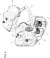
Figure 4 is a perspective view, on a further enlarged scale, of a tank assembly of the motor vehicle 1, with at least one portion shown as a cutaway, -
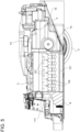
Figure 5 is a side view of the rear portion shown inFigure 2 , -
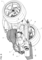
Figure 6 is a perspective view from below of the rear portion shown inFigure 2 , -
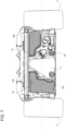
Figure 7 is a front view of the rear portion shown inFigure 2 , with parts removed to show the arrangement of the tank assembly, -
Figure 8 is a side section of the tank assembly, -
Figure 9 is a perspective view, with parts removed for clarity, showing a detail underneath the tank assembly, and -
Figure 10 is a schematic perspective view of components of an internal combustion engine of the motor vehicle inFigure 1 . - In
Figure 1 , the reference number 1 is used to indicate, as a whole, a motor vehicle equipped with tworear wheels 2, in particular driving wheels, receiving torque from aninternal combustion engine 3. -
Figure 1 shows a Cartesian system of axes X, Y and Z, respectively coinciding with a roll axis, a pitch axis, and a yaw axis of the motor vehicle 1. The axis X coincides with the direction of travel of the motor vehicle 1; the axis Y is horizontal and orthogonal to the axis X; the axis Z is orthogonal to the axes X, Y. - The
engine 3 is connected to thewheels 2 via a transmission apparatus comprising agearbox 4 and a differential of a known type, not shown. - The motor vehicle 1 further comprises a
body 5, which in turn includes achassis 6 and abodywork 7 carried by thechassis 6 and defining, among other things, the outer surfaces of the motor vehicle 1. - The motor vehicle 1 also comprises a
bottom 8 having a surface facing, in use, the road travelled by the motor vehicle 1. - The
engine 3 could be fuelled by different types of fuel, including, for example, petrol, diesel, synthetic fuel, etc., provided that the fuel is preferably normally in the liquid state. For clarity, the term normally refers to ambient temperature and pressure conditions. - In order to contain the fuel, the motor vehicle 1 also comprises two
tanks 10 arranged on the respective sides of theengine 3, in particular in front of theengine 3 or at a front end of theengine 3. - For clarity, terms like anterior, posterior, front, back, rear, etc., refer to the direction of travel of the motor vehicle 1 during use.
- Therefore, the
internal combustion engine 3 is arranged between thetanks 10 according to the pitch axis of the motor vehicle 1. More particularly, theinternal combustion engine 3 is arranged directly between thetanks 10 according to the pitch axis. In other words, according to the pitch axis, no other components are interposed between theinternal combustion engine 3 and thetanks 10. - The
tanks 10 are carried by thechassis 6 in a fixed position relative thereto. - Preferably, at least one of the
tanks 10 has at least one section basically triangular or trapezoidal in shape according to a horizontal plane, more precisely including the roll axis or the direction of travel of the motor vehicle 1, i.e., a plane orthogonal to the yaw axis of the motor vehicle 1. - As can be derived from the drawings, for example, the term basically herein implies a shape that technically resembles the rigorous one despite having, for example, rounded vertices, connected edges, slightly curved portions in place of one or more edges, small irregular sections at portions of one or more edges, localized recesses, and the like.
- The shape of the section referred to above is tapered, in greater detail, toward the rear of the motor vehicle 1.
- Preferably, both
tanks 10 have respective sections tapered according to a plane of section orthogonal to the yaw axis; in greater detail, the sections are tapered toward the rear of the motor vehicle 1. - Specifically, the
chassis 6 has a portion, in particular a rear portion, forming acell 6b, which in turn defines a compartment accommodating theengine 3, i.e., an engine compartment of the motor vehicle 1. - The
cell 6b has a basically trapezoidal shape in that it comprisesbeams 6c, which form a reticulation or framework extending basically in two planes orthogonal to the roll axis, the planes practically forming the bases of the trapezoidal shape, and on two ideal surfaces practically forming the sides of the trapezoidal shape. - The smaller base of the trapezoidal shape is posterior to the larger base.
- The ideal surfaces or sides are preferably curved and with concavities towards the outside of the motor vehicle 1.
- The concavities have respective areas of maximum recess towards the roll axis at the
rear wheels 2. - In this way, the
body 5 forms respective lateralaerodynamic channels 12 between the sides of thecell 6b and therear wheels 2. - More generally, the sides tend to converge towards the roll axis, thus forming the lateral
aerodynamic channels 12 between the sides and therear wheels 2. - In fact, the sides could also be flat, for example.
- In other words, the
body 5 is tapered or the sides are tapered towards the rear, thus forming the lateralaerodynamic channels 12. - Specifically, the
cell 6b has an upperreticular structure 6d in a plane orthogonal to a yaw axis of the motor vehicle 1 or a vertical axis. - The upper
reticular structure 6d delimits the engine compartment at the top and comprises twocross members 11 parallel to the pitch axis and twobeams 13 extending on the sides of thecell 6b in such a way as to basically form a trapezium with thebeams 11. - In addition, the upper
reticular structure 6d comprises twooblique beams 14, which diverge from an intermediate area of one of thecross members 11, in particular from the most anterior one, ending at respective vertices formed by the intersections of thebeams 13 with the other of thecross members 11. - In this way, the
oblique beams 14 delimit three triangular areas corresponding to three portions of the engine compartment respectively delimited at the top by the three triangular areas. The three portions of the engine compartment have triangular shapes or more precisely prismatic shapes with triangular bases. - Of the three portions of the engine compartment, the central one houses the
engine 3, whereas the remaining ones house thetanks 10, respectively. - In particular, the
tanks 10 completely occupy at least the corresponding two triangular areas and preferably the entire two portions of the engine compartment. - The
tanks 10 preferably have the same or a similar width according to the pitch axis and the same or a similar depth according to the roll axis. - In addition, the
tanks 10 have different heights according to the yaw axis. - Therefore, of the
tanks 10, the higher one will be indicated as the first tank, whereas the other one will be indicated as the second tank. - The first tank has or defines an inner volume comprising a
portion 10a having a height equal to or greater than that of theinner volume 10b of the second tank; moreover, the inner volume of the first tank comprises aportion 10c below theportion 10a and directly communicating with theportion 10a. - In other words, the
tanks 10 have respective upper ends having the same height or height level, whereas the first tank has a lower end having a height or height level lower than that of a lower end of the second tank. - In other words, still, the boundary between the
portions inner volume 10b. - In other words, still, the second tank extends above the
portion 10c, that is, in an area having a height or height level higher than that of theportion 10c. - In practice, the
portion 10c defines a "nurse" for the first tank. - The
tanks 10 communicate with each other; the motor vehicle 1 comprises apipe 15 which connects thetanks 10. - The
pipe 15 has two open ends at theportion 10a and theinner volume 10b, respectively, of the second tank. In other words, the ends of thepipe 15 communicate directly with thefirst portion 10a and theinner volume 10b, respectively. - The
pipe 15 has an axis, which can extend entirely in a plane orthogonal to the yaw axis. - Alternatively, each of the two end sections of the
pipe 15 may be slightly inclined downwards in relation to the plane orthogonal to the yaw axis. Here, the term slightly refers to an inclination less than 20°, preferably less than 10°. - In the latter case, the axis of the
pipe 15 may have an intermediate section extending in the plane orthogonal to the yaw axis. For example, the inclined ends or terminal sections of thepipe 15 extend directly from the intermediate section to therespective tanks 10. - In general, the
pipe 15 could comprise an intermediate section having a rectilinear axis parallel to the pitch axis. Specifically, the intermediate section is arranged anteriorly to thetanks 10, according to the direction of travel of the motor vehicle 1. -
Figure 8 shows a section of the first tank according to a plane of section orthogonal to the pitch axis. The end of thepipe 15 visible inFigure 8 ends with acontour 16, the projection of which on the section plane is oblique relative to the plane orthogonal to the yaw axis and points downwards. - In other words, the end of the
pipe 15 ends with a mouth opening pointing to the bottom of the first tank, i.e., pointing to theportion 10c or downwards, although the opening communicates directly with theportion 10a. - The motor vehicle 1 comprises one or
more pumps 17 to draw fuel from thetanks 10 and feed the fuel to theengine 3, for example through a known supply line, not shown. - Preferably, all the
pumps 17 are arranged within theportion 10c, and more precisely at the bottom of theportion 10c, i.e. of the first tank. - As shown in
Figure 8 , theportion 10c is externally delimited by a portion orshell 20 of the first tank. Similarly, theportion 10a is delimited by another portion orshell 20c of the first tank. - In turn, the
portion 20 comprises anend 20b projecting forwardly or towards the front of the motor vehicle 1 relative to the rest of theportion 20 according to the roll axis. - Therefore, the
end 20b projects forwardly or towards the front of the motor vehicle 1 relative to theportion 20c, according to the roll axis. - The
end 20b comprises alower wall 21 forming part of the bottom of the first tank, and anupper wall 22 facing thelower wall 21. - The
upper wall 22 projects cantilevered along the roll axis relative to awall 23 extending upwards. Thewall 23 could be part of theend 20b, but not necessarily; thewall 23 is more generally part of the first tank and could delimit an area of theportion 10a instead of or in addition to an area of theportion 10c. - Preferably, the
upper wall 22 has an opening for inspecting one of thepumps 17 arranged immediately below said opening. - Regardless of the presence or absence of the aforementioned opening, the
wall 23 has another opening for inspecting another of thepumps 17 arranged in an area of theportion 10c not directly delimited by theend 20b, i.e., inside the rest of theportion 20 relative to theend 20b, i.e., immediately below theportion 10a. - The first tank comprises
lids walls pumps 17, but that can be opened manually if required. - The volume delimited by the
end 20b and thus forming part of theportion 10c is arranged in an advanced position relative to theportion 10a, with reference to the direction of travel of the motor vehicle 1. - The
pumps 17, in particular those that can be inspected through the openings in thewalls portion 10c. - More particularly, all the
pumps 17 are aligned along a single straight axis parallel to the roll axis. - Within the first tank, specifically, the motor vehicle 1 comprises one or
more floats 26 andrespective detection devices 27 configured to determine the position of thefloats 26. - The function and construction characteristics of the
floats 26 and therelated detection devices 27 are known per se and will therefore not be described in detail. - Preferably, all the
floats 26 are arranged within the first tank. - Therefore, the motor vehicle 1 has no pumps and/or floats inside the second tank. In other words, the second tank contains no pumps and/or floats therein.
- More particularly, the second tank does not contain any type of device therein, i.e., it is adapted to only and exclusively contain fuel, in addition to, of course, the air normally present in the environment.
- As shown in
Figure 5 , theinternal combustion engine 3 comprises acrankcase 117 within which a plurality ofcylinders 118 are located. - Preferably but not necessarily, the
cylinders 118 are arranged in line, i.e., aligned along a straight axis, specifically parallel or more precisely coincident with the roll axis, as this solution allows the transversal dimensions of theengine 3 to be reduced and thus, among other things, allows more space for thetanks 10. In the embodiment shown in the attached figures there are sixcylinders 118 in line, but obviously the number and layout of thecylinders 118 may be different. - Each
cylinder 118 has a respective combustion chamber and arespective piston 119 mechanically connected to a drive shaft 120 (by means of a respective connecting rod) to transmit the force generated by combustion to thedrive shaft 120. Acylinder head 121 is coupled (connected) to thecrankcase 117 and forms the crown of the cylinders 118 (i.e., the upper closure of thecylinders 118 with the so-called "flame plate"). In the case of an in-line layout of thecylinders 118, asingle cylinder head 121 is provided, whereas in the case of a "V" layout of thecylinders 118, twotwin cylinder heads 121 are provided for the two banks ofcylinders 118. - The assembly of the
crankcase 117 and thecylinder head 121 constitutes the engine block of theinternal combustion engine 3. - In the embodiment shown in the attached figures, the
internal combustion engine 3 is arranged (oriented) longitudinally, i.e., thedrive shaft 120 is arranged (oriented) longitudinally, i.e., parallel to the roll axis, as this solution allows the transversal dimensions of theinternal combustion engine 3 to be reduced and therefore, among other things, allows more space for thetanks 10. According to other embodiments, not shown, theinternal combustion engine 3 is arranged (oriented) transversely, i.e., with thedrive shaft 120 oriented parallel to the pitch axis. - In the embodiment shown in the attached figures, the
internal combustion engine 3 is arranged in a central and/or rear position according to the roll axis, i.e., theinternal combustion engine 3 is arranged behind a passenger compartment (not shown) of the motor vehicle 1 and is located between the passenger compartment and the rear wheels 2 (the central arrangement as shown in the attached figures) or beyond the rear wheels 2 (the rear arrangement, not shown). - Furthermore, in the embodiment shown in the attached figures, the
internal combustion engine 3 is arranged in a central position according to the pitch axis, i.e., along the roll axis. - Each
cylinder 118 comprises two intake valves controlled by acamshaft 123 which receives motion from thedrive shaft 120 via a belt transmission 124 (Figure 10 ); as an alternative to thebelt transmission 124, a different type of transmission could be used, for example a chain transmission or a gear transmission. Furthermore, eachcylinder 118 comprises two exhaust valves controlled by acamshaft 126 which receives motion from thedrive shaft 120 via thebelt transmission 124. The intake valves, the exhaust valves and the corresponding control means, known per se and comprising return springs and thecamshafts cylinder head 121. - Each
cylinder 118 further comprises (at least) one injector 127 (schematically shown) configured to inject fuel into thecylinder 118 cyclically. - The
injector 127 is fed by thepumps 17 via the aforementioned supply line. - The injection of fuel into the
cylinder 118 may be direct but also partially or completely indirect, without any loss of generality. - In addition, each
cylinder 118 comprises at least one ignition device or spark plug, not shown, adapted to be cyclically activated to trigger the ignition of a mixture of air (comburent) and fuel present in the combustion chamber, in particular at the end of the compression stroke. - As shown in the attached figures, the
internal combustion engine 3 is oriented vertically, with thedrive shaft 120 arranged higher than thecylinders 118. In other words, theinternal combustion engine 3 is arranged "upside down" compared to the traditional arrangement whereby thecylinders 118 are at the top and thedrive shaft 120 is at the bottom. Accordingly, thecylinder head 121, which forms the crown of thecylinders 118, is arranged below thecrankcase 117 and represents the lowest part of theinternal combustion engine 3. - In other words, the
cylinder head 121 faces, in use, the road travelled by the motor vehicle 1. - The motor vehicle 1 comprises an
intake assembly 29 configured to draw air from the outside environment and convey it into thecylinders 118 of the internal combustion engine 3 (the entry of the air into thecylinders 118 is regulated by the intake valves mentioned above). - The
intake assembly 29 comprises an intake manifold communicating with all thecylinders 118; preferably, the entry of the air into the intake manifold is regulated by a throttle valve. - In addition, the motor vehicle 1 comprises an
exhaust assembly 32 configured to discharge exhaust gases from thecylinders 118 of theinternal combustion engine 3 into the external environment. - Among other things, the
exhaust assembly 32 comprises (at least) one exhaustgas treatment device 33, for example comprising a known catalyst, not shown. - As shown in
Figures 2 and3 , theintake assembly 29 comprises twointake lines 34, in particular arranged on the two sides of the motor vehicle 1. - The
lines 34 comprise respective ends defined by corresponding air intakes 35, in particular obtained through thebodywork 7. - Each
line 34 preferably comprises anair filter 36 at therespective air intake 35 to filter the air drawn through saidair intake 35. - Each
intake line 34 further comprises acompressor device 37 configured to increase the air pressure, with the aim of increasing the volumetric efficiency of thecylinders 118. - Downstream of the
related compressor device 37, eachintake line 34 comprises a correspondingintercooler 39. - In addition, the
intake lines 34 end downstream of theintercoolers 39 into asingle intake duct 40, particularly just above theinternal combustion engine 3. - In turn, the
intake duct 40 is connected to or communicates with the intake manifold 30. - The
intake duct 40 is not essential, so theintake lines 34 could have ended directly into the intake manifold. - Alternatively, rather than in parallel as in the embodiment just described, the
intercoolers 39 could have been arranged in series. In this case, theintake lines 34 would end at thecompressor devices 37, whereas theintake duct 40 would connect both outlets for the compressed air of thecompressor devices 37 to the intake manifold via theintercoolers 39 arranged in series. - Preferably, the
compressor devices 37 are arranged between theintercoolers 39 according to the pitch axis; in other words, theintercoolers 39 are on the respective sides of a compression assembly defined by thecompressor devices 37. - According to a preferred embodiment, one of or both the
intercoolers 39 are of the air/liquid, especially air/water, type. - In this way, the
intercoolers 39 may be smaller in size than corresponding air/air intercoolers. Therefore, since theintercoolers 39 are arranged on the sides of the compression assembly defined by thecompressor devices 37, the overall dimensions of theintercoolers 39 and thecompressor devices 37 according to the pitch axis are minimized. This allows thechassis 6 to be tapered at the rear of the motor vehicle 1 to a maximum extent and thus theaerodynamic channels 12 to be formed effectively. - As shown in
Figure 9 , theexhaust assembly 32 comprises anexhaust duct 41 which is arranged to receive the exhaust gases from thecylinders 118 of theinternal combustion engine 3. - The
exhaust duct 41 is connected to thecylinders 118 by respective channels originating from thecylinders 118 and ending into an inlet of theexhaust duct 41. - The
exhaust duct 41 comprises one or more exhaustgas treatment devices 33 arranged in series. - Downstream of the exhaust
gas treatment devices 33, theexhaust duct 41 preferably ends with a single pipe leading into anoutlet port 46. According to other embodiments, not shown, theexhaust duct 33 may end with several pipes leading intorespective outlet ports 46. - Preferably, all the occurring
outlet ports 46 are arranged on one of the sides of thecell 6b of thechassis 6. - In other words, the
outlet port 46 is arranged asymmetrically on only one side of the motor vehicle 1 and is located between arear wheel 2 and afront wheel 2b on the same side of the motor vehicle 1. - In particular, the
outlet port 46 is obtained through a side of thebodywork 7. - Preferably, the
gearbox 4 is aligned with theinternal combustion engine 3 according to the roll axis and is arranged behind theinternal combustion engine 3. In particular, thegearbox 4 is aligned with an upper portion of the engine block (crankcase 117 and cylinder head 121) of theinternal combustion engine 3. In other words, thegearbox 4 is aligned with the upper part of thecrankcase 117. - More particularly, the
gearbox 4 comprises at least one primary shaft (not shown) connected to thedrive shaft 120 via a known transmission, not shown, for example comprising gears, and/or a dual-mass flywheel, and/or the like. - The
gearbox 4 comprises anouter casing 73, which is tapered toward the rear so that the height of thecasing 73 decreases progressively from the front to the rear. In other words, a front wall of thecasing 73 extends in height more than a rear wall of thecasing 73. - In particular, the
casing 73 at the bottom has abottom wall 74 which is inclined in relation to the roll axis due to the tapered shape of thecasing 73. - In addition, as can be seen in
Figure 3 , theintercoolers 39 are arranged on the respective sides of the gearbox 4 (i.e., on the sides of thecasing 37 of the gearbox 4). - Furthermore, the
intercoolers 39 are preferably arranged above the gearbox 4 (i.e., above thecasing 37 of the gearbox 4). More precisely, at least one portion of theintercoolers 39 is arranged above or at a higher level than that of thegearbox 4 or itscasing 37, but it is not necessary that theintercoolers 39 are entirely above thegearbox 4 or itscasing 37, although they may be so according to some embodiments, not shown. - According to the embodiment shown herein, the compression assembly comprising the two
compressor devices 37, in particular twin or equal compressor devices, is arranged behind (at the rear of) the engine block (consisting of thecrankcase 117 and the cylinder head 121) of theinternal combustion engine 3. - Moreover, the compression assembly is arranged higher than the engine block of the
internal combustion engine 3. In other words, at least one portion of the compression assembly or more specifically at least two respective portions of thecompressor devices 37 are arranged above or at a higher level than that of the engine block of theinternal combustion engine 3. - In addition, the compression assembly is arranged higher than the
gearbox 4 or itscasing 73. In other words, at least one portion of the compression assembly or more specifically at least two respective portions of thecompressor devices 37 are arranged above or at a higher level than that of thegearbox 7 or itscasing 73. - In particular, the compression assembly or a portion thereof is arranged directly above the
gearbox 7 or itscasing 73. - Similarly, in particular, the
intercoolers 39 are arranged higher than the engine block of theinternal combustion engine 3 and are located behind the engine block of theinternal combustion engine 3. - The
compressor devices 37 comprise or are defined by two compressors, e.g., twin (identical) compressors. The two compressors are preferably turbomachines, more preferably centrifugal compressors. - The
compressor devices 37 are aligned with each other along the pitch axis, i.e., side-by-side and at the same height. - The
compressor devices 37 are preferably powered by theinternal combustion engine 3 or more precisely by the rotation of thedrive shaft 120. - In particular, the motor vehicle 1 comprises a transmission, more particularly of the gear type with a clutch, configured to selectively transmit (specifically when the clutch is engaged) at least part of the power delivered by the
engine 3 or the rotation of thedrive shaft 120 to bothcompressor devices 37, thus powering them. - More particularly, the latter transmission comprises the primary shaft of the
gearbox 4. In other words, thecompressor devices 37 receive power from the primary shaft of thegearbox 4. - According to alternative embodiments, the transmission comprises the
gearbox 4 or a portion thereof, such that the rotation of thedrive shaft 120 is transmitted to thecompressor devices 37 in a reduced manner via one of the gears or transmission ratios of thegearbox 4. - Preferably, the motor vehicle 1 does not have turbochargers configured to supercharge the
internal combustion engine 3. - In other words, the
compressor devices 37 are not powered by turbines driven by the exhaust gases of theinternal combustion engine 3. - This makes the turbines unnecessary, saving useful space, for example for the definition of the
aerodynamic channels 12 or for the tapering of thechassis 6 towards the rear of the motor vehicle 1. - Preferably, the
exhaust assembly 32 is at least partially housed within a compartment obtained below the second tank, as best visible inFigure 9 . - In particular, the compartment in which the
exhaust assembly 32 is at least partially housed is arranged at the same height as theportion 10c, more particularly on the opposite side of theinternal combustion engine 3. - As shown in
Figure 5 , the motor vehicle 1 comprises a rearaerodynamic puller 75, which faces, in use, the road travelled by the motor vehicle 1, starts at a rear wall of the engine block (consisting of thecrankcase 117 and the cylinder head 121) of theinternal combustion engine 3, and is arranged below the gearbox 4 (i.e., below the casing 73). - According to a preferred embodiment, the
wall 74 of thecasing 73 has the same inclination as the rearaerodynamic puller 75. - In other words, the
wall 74 reproduces the shape of the rearaerodynamic puller 75 and has the same inclination. In this way, the rearaerodynamic puller 75 makes use of all the space available under the gearbox 4 (i.e., under the casing 73). - The
puller 75 is inclined in relation to the horizontal plane along which thebottom 8 extends. - The advantages of the motor vehicle 1 according to the invention are clear from the foregoing.
- The arrangement of the
tanks 10 in relation to theinternal combustion engine 3 together with the basically triangular shape of thetanks 10 allows considerable space saving with associated advantages in the freedom of positioning the other devices auxiliary to the operation of theinternal combustion engine 3. - More particularly, the reduced height of the second of the
tanks 10 frees a compartment immediately below the same second tank; the compartment can advantageously be used for housing one or more auxiliary devices. Specifically, in fact, theexhaust assembly 32 is at least partially housed in the compartment. - In this way, the
exhaust assembly 32 extends laterally until it ends at theoutlet port 46, without occupying spaces in the rear area of the motor vehicle 1. - This contributes to the tapering of the
chassis 6, resulting in the design of theaerodynamic channels 12. - In addition, the
portion 10c provides a fuel storage area that always remains with a minimum amount of fuel, so that thepumps 17 can always feed theinternal combustion engine 3. - Indeed, even if the motor vehicle 1 were to travel around a curve, the rise of the fuel from the
portion 10c, resulting in the passage of fuel into theinner volume 10b via thepipe 15, remains limited, so that in any case at least some fuel still remains in theportion 10c and can therefore be drawn by thepumps 17. - Due to the layout and shape of the
tanks 10, all devices such as thepumps 17 and thefloats 26 may be concentrated in the first of thetanks 10, thus allowing the second tank to be emptied by these devices. - Therefore, the fuel storage capacity of the second of the
tanks 10 is consequently maximized. - The
pipe 15 allows effective communication between thetanks 10 according to the principle of communicating vessels. In this way, the overall storage capacity of thetanks 10 is optimal. - Lastly, it is clear that modifications and variations may be made to the supercharging device according to the invention, without however departing from the scope of protection defined by the claims.
- In particular, each of the devices depicted schematically in the figures is independent of the other details and is specifically designed to solve specific technical problems in isolation from the other details.
- In addition, the number of components described and illustrated may be different. In particular, this applies to all the duplicate components, i.e., twin, or identical components. In fact, all the components mentioned with a number of two or more can be replaced by a single related component. In other words, the number can be reduced to one.
Claims (10)
- A motor vehicle comprising- an internal combustion engine (3) extending along a direction parallel to a roll axis of the motor vehicle (1),- a first and a second tank (10) for containing a fuel for feeding the internal combustion engine (3),wherein the internal combustion engine (3) is arranged between the first and second tanks (10) according to a pitch axis of the motor vehicle (1),characterized in that the first tank has a first height according to a yaw axis of the motor vehicle (1) greater than a second height of the second tank according to the yaw axis.
- The motor vehicle according to claim 1, wherein the second tank defines a second inner volume (10b), and wherein the first tank defines a first inner volume having a first portion (10a) having a third height according to the yaw axis equal to a fourth height of the second inner volume (10b) according to the yaw axis, the first inner volume having in addition a second portion (10c) below the first portion (10a) and directly communicating with the first portion (10a).
- The motor vehicle according to claim 2, further comprising an exhaust assembly (32) configured to discharge exhaust gases produced by the internal combustion engine (3) into the environment outside the motor vehicle (1), wherein the exhaust assembly (32) is at least partially housed in a compartment positioned immediately below the second tank.
- The motor vehicle according to claim 2 or 3, comprising a pipe (15), which connects the first and second tanks (10) by having two ends directly communicating with the first portion (10a) and the second inner volume (10b), respectively.
- The motor vehicle according to claim 4, wherein the pipe (15) comprises an intermediate section having a rectilinear axis parallel to the pitch axis.
- The motor vehicle according to claim 4 or 5, comprising a plurality of pumps (17) configured to draw fuel from the first and second tanks and feed the fuel to the internal combustion engine (3) via a supply line, the pumps (17) being all arranged within the second portion (10c).
- The motor vehicle according to claim 6, wherein all the pumps (17) are arranged at the bottom of the second portion (10c).
- The motor vehicle according to any one of claims 2 to 7, wherein the first tank comprises a first and a second shell (20c, 20) respectively externally delimiting the first and the second portion (10a, 10c), the second shell (20) comprising an end (20b) projecting forwardly relative to the first shell (20c) according to the roll axis.
- The motor vehicle according to any of the preceding claims, wherein the first and second tanks (10) have respective sections according to a plane of section orthogonal to the yaw axis, the sections having a tapered shape toward a rear of the motor vehicle (1).
- The motor vehicle according to claim 9, wherein the shape of the sections is basically triangular.
Applications Claiming Priority (1)
| Application Number | Priority Date | Filing Date | Title |
|---|---|---|---|
| IT102023000005862A IT202300005862A1 (en) | 2023-03-28 | 2023-03-28 | MOTOR VEHICLE WITH AN IMPROVED ARRANGEMENT OF FUEL TANKS |
Publications (2)
| Publication Number | Publication Date |
|---|---|
| EP4438369A1 true EP4438369A1 (en) | 2024-10-02 |
| EP4438369B1 EP4438369B1 (en) | 2026-01-14 |
Family
ID=86942932
Family Applications (1)
| Application Number | Title | Priority Date | Filing Date |
|---|---|---|---|
| EP24165416.9A Active EP4438369B1 (en) | 2023-03-28 | 2024-03-22 | Motor vehicle with an improved arrangement of fuel tanks |
Country Status (4)
| Country | Link |
|---|---|
| US (1) | US20240326582A1 (en) |
| EP (1) | EP4438369B1 (en) |
| CN (1) | CN118722198A (en) |
| IT (1) | IT202300005862A1 (en) |
Citations (3)
| Publication number | Priority date | Publication date | Assignee | Title |
|---|---|---|---|---|
| EP0860315B1 (en) * | 1997-02-21 | 2001-12-19 | Still Gmbh | Forklift truck |
| US20190202500A1 (en) * | 2018-01-03 | 2019-07-04 | Ford Global Technologies, Llc | Hybrid energy storage and delivery devices for hybrid electric vehicles |
| CN110077214A (en) * | 2018-01-24 | 2019-08-02 | 福特全球技术公司 | For being especially the assembly of the vehicle of hybrid electric vehicle, and the vehicle of especially hybrid electric vehicle |
-
2023
- 2023-03-28 IT IT102023000005862A patent/IT202300005862A1/en unknown
-
2024
- 2024-03-22 EP EP24165416.9A patent/EP4438369B1/en active Active
- 2024-03-28 US US18/619,640 patent/US20240326582A1/en active Pending
- 2024-03-28 CN CN202410362600.6A patent/CN118722198A/en active Pending
Patent Citations (3)
| Publication number | Priority date | Publication date | Assignee | Title |
|---|---|---|---|---|
| EP0860315B1 (en) * | 1997-02-21 | 2001-12-19 | Still Gmbh | Forklift truck |
| US20190202500A1 (en) * | 2018-01-03 | 2019-07-04 | Ford Global Technologies, Llc | Hybrid energy storage and delivery devices for hybrid electric vehicles |
| CN110077214A (en) * | 2018-01-24 | 2019-08-02 | 福特全球技术公司 | For being especially the assembly of the vehicle of hybrid electric vehicle, and the vehicle of especially hybrid electric vehicle |
Also Published As
| Publication number | Publication date |
|---|---|
| EP4438369B1 (en) | 2026-01-14 |
| CN118722198A (en) | 2024-10-01 |
| US20240326582A1 (en) | 2024-10-03 |
| IT202300005862A1 (en) | 2024-09-28 |
Similar Documents
| Publication | Publication Date | Title |
|---|---|---|
| EP4438866A1 (en) | Motor vehicle with an improved arrangement of intake air intercoolers | |
| CA1193160A (en) | Compact ram tube engine air intake manifold | |
| US5553586A (en) | Engine and outboard engine structure | |
| US7597088B2 (en) | Apparatus and method for boosting engine performance | |
| EP0853038B1 (en) | Engine | |
| US4981115A (en) | Intake system for V-type engine | |
| US10724469B2 (en) | Cylinder block assembly | |
| CN204060916U (en) | For the intake duct of gaseous fuel explosive motor and the configuration of valve seat | |
| EP0636776A1 (en) | Combustion controller for a spark ignition type two-cycle engine | |
| US4878460A (en) | Intake system for V-type internal combustion engine | |
| JPS6325162B2 (en) | ||
| EP4438369B1 (en) | Motor vehicle with an improved arrangement of fuel tanks | |
| JP2000080965A (en) | Intake device for internal combustion engine | |
| JP2024031916A (en) | Turbine assembly for internal combustion engine | |
| EP4375480B1 (en) | Car provided with an internal combustion engine | |
| US4466389A (en) | Intake-manifold | |
| WO2025126543A1 (en) | Engine | |
| CN117621796A (en) | A motor vehicle having an internal combustion engine arranged with the drive shaft on top | |
| CN121671315A (en) | All-terrain vehicle | |
| CN101560908A (en) | Integrated pressure booster for combined air supply | |
| JPH02104921A (en) | Intake structure of v-engine | |
| JP2005271879A (en) | Outside air intake structure of outboard motor | |
| JPH01110835A (en) | Horizontally opposed type engine |
Legal Events
| Date | Code | Title | Description |
|---|---|---|---|
| PUAI | Public reference made under article 153(3) epc to a published international application that has entered the european phase |
Free format text: ORIGINAL CODE: 0009012 |
|
| STAA | Information on the status of an ep patent application or granted ep patent |
Free format text: STATUS: THE APPLICATION HAS BEEN PUBLISHED |
|
| AK | Designated contracting states |
Kind code of ref document: A1 Designated state(s): AL AT BE BG CH CY CZ DE DK EE ES FI FR GB GR HR HU IE IS IT LI LT LU LV MC ME MK MT NL NO PL PT RO RS SE SI SK SM TR |
|
| STAA | Information on the status of an ep patent application or granted ep patent |
Free format text: STATUS: REQUEST FOR EXAMINATION WAS MADE |
|
| 17P | Request for examination filed |
Effective date: 20250402 |
|
| GRAP | Despatch of communication of intention to grant a patent |
Free format text: ORIGINAL CODE: EPIDOSNIGR1 |
|
| STAA | Information on the status of an ep patent application or granted ep patent |
Free format text: STATUS: GRANT OF PATENT IS INTENDED |
|
| INTG | Intention to grant announced |
Effective date: 20250807 |
|
| RIN1 | Information on inventor provided before grant (corrected) |
Inventor name: FAVARETTO, FABRIZIO |
|
| GRAS | Grant fee paid |
Free format text: ORIGINAL CODE: EPIDOSNIGR3 |
|
| GRAA | (expected) grant |
Free format text: ORIGINAL CODE: 0009210 |
|
| STAA | Information on the status of an ep patent application or granted ep patent |
Free format text: STATUS: THE PATENT HAS BEEN GRANTED |
|
| AK | Designated contracting states |
Kind code of ref document: B1 Designated state(s): AL AT BE BG CH CY CZ DE DK EE ES FI FR GB GR HR HU IE IS IT LI LT LU LV MC ME MK MT NL NO PL PT RO RS SE SI SK SM TR |
|
| REG | Reference to a national code |
Ref country code: CH Ref legal event code: F10 Free format text: ST27 STATUS EVENT CODE: U-0-0-F10-F00 (AS PROVIDED BY THE NATIONAL OFFICE) Effective date: 20260114 Ref country code: GB Ref legal event code: FG4D |
|
| REG | Reference to a national code |
Ref country code: DE Ref legal event code: R096 Ref document number: 602024001999 Country of ref document: DE |
|
| REG | Reference to a national code |
Ref country code: IE Ref legal event code: FG4D |
|
| PGFP | Annual fee paid to national office [announced via postgrant information from national office to epo] |
Ref country code: DE Payment date: 20260320 Year of fee payment: 3 |
|
| PGFP | Annual fee paid to national office [announced via postgrant information from national office to epo] |
Ref country code: AT Payment date: 20260301 Year of fee payment: 3 |
|
| PGFP | Annual fee paid to national office [announced via postgrant information from national office to epo] |
Ref country code: FR Payment date: 20260323 Year of fee payment: 3 |