EP4438367A1 - Drive motor stalling cooling method and apparatus for vehicle, and vehicle - Google Patents
Drive motor stalling cooling method and apparatus for vehicle, and vehicle Download PDFInfo
- Publication number
- EP4438367A1 EP4438367A1 EP23759259.7A EP23759259A EP4438367A1 EP 4438367 A1 EP4438367 A1 EP 4438367A1 EP 23759259 A EP23759259 A EP 23759259A EP 4438367 A1 EP4438367 A1 EP 4438367A1
- Authority
- EP
- European Patent Office
- Prior art keywords
- preset
- driving motor
- vehicle
- engine
- cooling
- Prior art date
- Legal status (The legal status is an assumption and is not a legal conclusion. Google has not performed a legal analysis and makes no representation as to the accuracy of the status listed.)
- Granted
Links
Images


Classifications
-
- B—PERFORMING OPERATIONS; TRANSPORTING
- B60—VEHICLES IN GENERAL
- B60K—ARRANGEMENT OR MOUNTING OF PROPULSION UNITS OR OF TRANSMISSIONS IN VEHICLES; ARRANGEMENT OR MOUNTING OF PLURAL DIVERSE PRIME-MOVERS IN VEHICLES; AUXILIARY DRIVES FOR VEHICLES; INSTRUMENTATION OR DASHBOARDS FOR VEHICLES; ARRANGEMENTS IN CONNECTION WITH COOLING, AIR INTAKE, GAS EXHAUST OR FUEL SUPPLY OF PROPULSION UNITS IN VEHICLES
- B60K11/00—Arrangement in connection with cooling of propulsion units
- B60K11/06—Arrangement in connection with cooling of propulsion units with air cooling
-
- B—PERFORMING OPERATIONS; TRANSPORTING
- B60—VEHICLES IN GENERAL
- B60K—ARRANGEMENT OR MOUNTING OF PROPULSION UNITS OR OF TRANSMISSIONS IN VEHICLES; ARRANGEMENT OR MOUNTING OF PLURAL DIVERSE PRIME-MOVERS IN VEHICLES; AUXILIARY DRIVES FOR VEHICLES; INSTRUMENTATION OR DASHBOARDS FOR VEHICLES; ARRANGEMENTS IN CONNECTION WITH COOLING, AIR INTAKE, GAS EXHAUST OR FUEL SUPPLY OF PROPULSION UNITS IN VEHICLES
- B60K11/00—Arrangement in connection with cooling of propulsion units
- B60K11/02—Arrangement in connection with cooling of propulsion units with liquid cooling
-
- B—PERFORMING OPERATIONS; TRANSPORTING
- B60—VEHICLES IN GENERAL
- B60K—ARRANGEMENT OR MOUNTING OF PROPULSION UNITS OR OF TRANSMISSIONS IN VEHICLES; ARRANGEMENT OR MOUNTING OF PLURAL DIVERSE PRIME-MOVERS IN VEHICLES; AUXILIARY DRIVES FOR VEHICLES; INSTRUMENTATION OR DASHBOARDS FOR VEHICLES; ARRANGEMENTS IN CONNECTION WITH COOLING, AIR INTAKE, GAS EXHAUST OR FUEL SUPPLY OF PROPULSION UNITS IN VEHICLES
- B60K6/00—Arrangement or mounting of plural diverse prime-movers for mutual or common propulsion, e.g. hybrid propulsion systems comprising electric motors and internal combustion engines
- B60K6/20—Arrangement or mounting of plural diverse prime-movers for mutual or common propulsion, e.g. hybrid propulsion systems comprising electric motors and internal combustion engines the prime-movers consisting of electric motors and internal combustion engines, e.g. HEVs
- B60K6/22—Arrangement or mounting of plural diverse prime-movers for mutual or common propulsion, e.g. hybrid propulsion systems comprising electric motors and internal combustion engines the prime-movers consisting of electric motors and internal combustion engines, e.g. HEVs characterised by apparatus, components or means specially adapted for HEVs
-
- B—PERFORMING OPERATIONS; TRANSPORTING
- B60—VEHICLES IN GENERAL
- B60W—CONJOINT CONTROL OF VEHICLE SUB-UNITS OF DIFFERENT TYPE OR DIFFERENT FUNCTION; CONTROL SYSTEMS SPECIALLY ADAPTED FOR HYBRID VEHICLES; ROAD VEHICLE DRIVE CONTROL SYSTEMS FOR PURPOSES NOT RELATED TO THE CONTROL OF A PARTICULAR SUB-UNIT
- B60W10/00—Conjoint control of vehicle sub-units of different type or different function
- B60W10/04—Conjoint control of vehicle sub-units of different type or different function including control of propulsion units
- B60W10/06—Conjoint control of vehicle sub-units of different type or different function including control of propulsion units including control of combustion engines
-
- B—PERFORMING OPERATIONS; TRANSPORTING
- B60—VEHICLES IN GENERAL
- B60W—CONJOINT CONTROL OF VEHICLE SUB-UNITS OF DIFFERENT TYPE OR DIFFERENT FUNCTION; CONTROL SYSTEMS SPECIALLY ADAPTED FOR HYBRID VEHICLES; ROAD VEHICLE DRIVE CONTROL SYSTEMS FOR PURPOSES NOT RELATED TO THE CONTROL OF A PARTICULAR SUB-UNIT
- B60W10/00—Conjoint control of vehicle sub-units of different type or different function
- B60W10/04—Conjoint control of vehicle sub-units of different type or different function including control of propulsion units
- B60W10/08—Conjoint control of vehicle sub-units of different type or different function including control of propulsion units including control of electric propulsion units, e.g. motors or generators
-
- B—PERFORMING OPERATIONS; TRANSPORTING
- B60—VEHICLES IN GENERAL
- B60W—CONJOINT CONTROL OF VEHICLE SUB-UNITS OF DIFFERENT TYPE OR DIFFERENT FUNCTION; CONTROL SYSTEMS SPECIALLY ADAPTED FOR HYBRID VEHICLES; ROAD VEHICLE DRIVE CONTROL SYSTEMS FOR PURPOSES NOT RELATED TO THE CONTROL OF A PARTICULAR SUB-UNIT
- B60W10/00—Conjoint control of vehicle sub-units of different type or different function
- B60W10/30—Conjoint control of vehicle sub-units of different type or different function including control of auxiliary equipment, e.g. air-conditioning compressors or oil pumps
-
- B—PERFORMING OPERATIONS; TRANSPORTING
- B60—VEHICLES IN GENERAL
- B60W—CONJOINT CONTROL OF VEHICLE SUB-UNITS OF DIFFERENT TYPE OR DIFFERENT FUNCTION; CONTROL SYSTEMS SPECIALLY ADAPTED FOR HYBRID VEHICLES; ROAD VEHICLE DRIVE CONTROL SYSTEMS FOR PURPOSES NOT RELATED TO THE CONTROL OF A PARTICULAR SUB-UNIT
- B60W20/00—Control systems specially adapted for hybrid vehicles
-
- B—PERFORMING OPERATIONS; TRANSPORTING
- B60—VEHICLES IN GENERAL
- B60W—CONJOINT CONTROL OF VEHICLE SUB-UNITS OF DIFFERENT TYPE OR DIFFERENT FUNCTION; CONTROL SYSTEMS SPECIALLY ADAPTED FOR HYBRID VEHICLES; ROAD VEHICLE DRIVE CONTROL SYSTEMS FOR PURPOSES NOT RELATED TO THE CONTROL OF A PARTICULAR SUB-UNIT
- B60W20/00—Control systems specially adapted for hybrid vehicles
- B60W20/40—Controlling the engagement or disengagement of prime movers, e.g. for transition between prime movers
-
- B—PERFORMING OPERATIONS; TRANSPORTING
- B60—VEHICLES IN GENERAL
- B60K—ARRANGEMENT OR MOUNTING OF PROPULSION UNITS OR OF TRANSMISSIONS IN VEHICLES; ARRANGEMENT OR MOUNTING OF PLURAL DIVERSE PRIME-MOVERS IN VEHICLES; AUXILIARY DRIVES FOR VEHICLES; INSTRUMENTATION OR DASHBOARDS FOR VEHICLES; ARRANGEMENTS IN CONNECTION WITH COOLING, AIR INTAKE, GAS EXHAUST OR FUEL SUPPLY OF PROPULSION UNITS IN VEHICLES
- B60K1/00—Arrangement or mounting of electrical propulsion units
- B60K2001/003—Arrangement or mounting of electrical propulsion units with means for cooling the electrical propulsion units
- B60K2001/006—Arrangement or mounting of electrical propulsion units with means for cooling the electrical propulsion units the electric motors
-
- B—PERFORMING OPERATIONS; TRANSPORTING
- B60—VEHICLES IN GENERAL
- B60W—CONJOINT CONTROL OF VEHICLE SUB-UNITS OF DIFFERENT TYPE OR DIFFERENT FUNCTION; CONTROL SYSTEMS SPECIALLY ADAPTED FOR HYBRID VEHICLES; ROAD VEHICLE DRIVE CONTROL SYSTEMS FOR PURPOSES NOT RELATED TO THE CONTROL OF A PARTICULAR SUB-UNIT
- B60W50/00—Details of control systems for road vehicle drive control not related to the control of a particular sub-unit, e.g. process diagnostic or vehicle driver interfaces
- B60W2050/0062—Adapting control system settings
- B60W2050/0075—Automatic parameter input, automatic initialising or calibrating means
- B60W2050/0083—Setting, resetting, calibration
-
- B—PERFORMING OPERATIONS; TRANSPORTING
- B60—VEHICLES IN GENERAL
- B60W—CONJOINT CONTROL OF VEHICLE SUB-UNITS OF DIFFERENT TYPE OR DIFFERENT FUNCTION; CONTROL SYSTEMS SPECIALLY ADAPTED FOR HYBRID VEHICLES; ROAD VEHICLE DRIVE CONTROL SYSTEMS FOR PURPOSES NOT RELATED TO THE CONTROL OF A PARTICULAR SUB-UNIT
- B60W2400/00—Indexing codes relating to detected, measured or calculated conditions or factors
-
- B—PERFORMING OPERATIONS; TRANSPORTING
- B60—VEHICLES IN GENERAL
- B60W—CONJOINT CONTROL OF VEHICLE SUB-UNITS OF DIFFERENT TYPE OR DIFFERENT FUNCTION; CONTROL SYSTEMS SPECIALLY ADAPTED FOR HYBRID VEHICLES; ROAD VEHICLE DRIVE CONTROL SYSTEMS FOR PURPOSES NOT RELATED TO THE CONTROL OF A PARTICULAR SUB-UNIT
- B60W2510/00—Input parameters relating to a particular sub-units
- B60W2510/08—Electric propulsion units
- B60W2510/083—Torque
-
- B—PERFORMING OPERATIONS; TRANSPORTING
- B60—VEHICLES IN GENERAL
- B60W—CONJOINT CONTROL OF VEHICLE SUB-UNITS OF DIFFERENT TYPE OR DIFFERENT FUNCTION; CONTROL SYSTEMS SPECIALLY ADAPTED FOR HYBRID VEHICLES; ROAD VEHICLE DRIVE CONTROL SYSTEMS FOR PURPOSES NOT RELATED TO THE CONTROL OF A PARTICULAR SUB-UNIT
- B60W2510/00—Input parameters relating to a particular sub-units
- B60W2510/08—Electric propulsion units
- B60W2510/087—Temperature
-
- B—PERFORMING OPERATIONS; TRANSPORTING
- B60—VEHICLES IN GENERAL
- B60W—CONJOINT CONTROL OF VEHICLE SUB-UNITS OF DIFFERENT TYPE OR DIFFERENT FUNCTION; CONTROL SYSTEMS SPECIALLY ADAPTED FOR HYBRID VEHICLES; ROAD VEHICLE DRIVE CONTROL SYSTEMS FOR PURPOSES NOT RELATED TO THE CONTROL OF A PARTICULAR SUB-UNIT
- B60W2510/00—Input parameters relating to a particular sub-units
- B60W2510/10—Change speed gearings
- B60W2510/1005—Transmission ratio engaged
-
- B—PERFORMING OPERATIONS; TRANSPORTING
- B60—VEHICLES IN GENERAL
- B60W—CONJOINT CONTROL OF VEHICLE SUB-UNITS OF DIFFERENT TYPE OR DIFFERENT FUNCTION; CONTROL SYSTEMS SPECIALLY ADAPTED FOR HYBRID VEHICLES; ROAD VEHICLE DRIVE CONTROL SYSTEMS FOR PURPOSES NOT RELATED TO THE CONTROL OF A PARTICULAR SUB-UNIT
- B60W2510/00—Input parameters relating to a particular sub-units
- B60W2510/30—Auxiliary equipments
-
- B—PERFORMING OPERATIONS; TRANSPORTING
- B60—VEHICLES IN GENERAL
- B60W—CONJOINT CONTROL OF VEHICLE SUB-UNITS OF DIFFERENT TYPE OR DIFFERENT FUNCTION; CONTROL SYSTEMS SPECIALLY ADAPTED FOR HYBRID VEHICLES; ROAD VEHICLE DRIVE CONTROL SYSTEMS FOR PURPOSES NOT RELATED TO THE CONTROL OF A PARTICULAR SUB-UNIT
- B60W2520/00—Input parameters relating to overall vehicle dynamics
- B60W2520/04—Vehicle stop
-
- B—PERFORMING OPERATIONS; TRANSPORTING
- B60—VEHICLES IN GENERAL
- B60W—CONJOINT CONTROL OF VEHICLE SUB-UNITS OF DIFFERENT TYPE OR DIFFERENT FUNCTION; CONTROL SYSTEMS SPECIALLY ADAPTED FOR HYBRID VEHICLES; ROAD VEHICLE DRIVE CONTROL SYSTEMS FOR PURPOSES NOT RELATED TO THE CONTROL OF A PARTICULAR SUB-UNIT
- B60W2520/00—Input parameters relating to overall vehicle dynamics
- B60W2520/10—Longitudinal speed
-
- B—PERFORMING OPERATIONS; TRANSPORTING
- B60—VEHICLES IN GENERAL
- B60W—CONJOINT CONTROL OF VEHICLE SUB-UNITS OF DIFFERENT TYPE OR DIFFERENT FUNCTION; CONTROL SYSTEMS SPECIALLY ADAPTED FOR HYBRID VEHICLES; ROAD VEHICLE DRIVE CONTROL SYSTEMS FOR PURPOSES NOT RELATED TO THE CONTROL OF A PARTICULAR SUB-UNIT
- B60W2710/00—Output or target parameters relating to a particular sub-units
- B60W2710/06—Combustion engines, Gas turbines
- B60W2710/0644—Engine speed
-
- B—PERFORMING OPERATIONS; TRANSPORTING
- B60—VEHICLES IN GENERAL
- B60W—CONJOINT CONTROL OF VEHICLE SUB-UNITS OF DIFFERENT TYPE OR DIFFERENT FUNCTION; CONTROL SYSTEMS SPECIALLY ADAPTED FOR HYBRID VEHICLES; ROAD VEHICLE DRIVE CONTROL SYSTEMS FOR PURPOSES NOT RELATED TO THE CONTROL OF A PARTICULAR SUB-UNIT
- B60W2710/00—Output or target parameters relating to a particular sub-units
- B60W2710/06—Combustion engines, Gas turbines
- B60W2710/0677—Engine power
-
- B—PERFORMING OPERATIONS; TRANSPORTING
- B60—VEHICLES IN GENERAL
- B60W—CONJOINT CONTROL OF VEHICLE SUB-UNITS OF DIFFERENT TYPE OR DIFFERENT FUNCTION; CONTROL SYSTEMS SPECIALLY ADAPTED FOR HYBRID VEHICLES; ROAD VEHICLE DRIVE CONTROL SYSTEMS FOR PURPOSES NOT RELATED TO THE CONTROL OF A PARTICULAR SUB-UNIT
- B60W2710/00—Output or target parameters relating to a particular sub-units
- B60W2710/30—Auxiliary equipments
-
- B—PERFORMING OPERATIONS; TRANSPORTING
- B60—VEHICLES IN GENERAL
- B60W—CONJOINT CONTROL OF VEHICLE SUB-UNITS OF DIFFERENT TYPE OR DIFFERENT FUNCTION; CONTROL SYSTEMS SPECIALLY ADAPTED FOR HYBRID VEHICLES; ROAD VEHICLE DRIVE CONTROL SYSTEMS FOR PURPOSES NOT RELATED TO THE CONTROL OF A PARTICULAR SUB-UNIT
- B60W30/00—Purposes of road vehicle drive control systems not related to the control of a particular sub-unit, e.g. of systems using conjoint control of vehicle sub-units
- B60W30/18—Propelling the vehicle
- B60W30/18009—Propelling the vehicle related to particular drive situations
- B60W30/18063—Creeping
-
- B—PERFORMING OPERATIONS; TRANSPORTING
- B60—VEHICLES IN GENERAL
- B60Y—INDEXING SCHEME RELATING TO ASPECTS CROSS-CUTTING VEHICLE TECHNOLOGY
- B60Y2200/00—Type of vehicle
- B60Y2200/90—Vehicles comprising electric prime movers
- B60Y2200/92—Hybrid vehicles
-
- Y—GENERAL TAGGING OF NEW TECHNOLOGICAL DEVELOPMENTS; GENERAL TAGGING OF CROSS-SECTIONAL TECHNOLOGIES SPANNING OVER SEVERAL SECTIONS OF THE IPC; TECHNICAL SUBJECTS COVERED BY FORMER USPC CROSS-REFERENCE ART COLLECTIONS [XRACs] AND DIGESTS
- Y02—TECHNOLOGIES OR APPLICATIONS FOR MITIGATION OR ADAPTATION AGAINST CLIMATE CHANGE
- Y02T—CLIMATE CHANGE MITIGATION TECHNOLOGIES RELATED TO TRANSPORTATION
- Y02T10/00—Road transport of goods or passengers
- Y02T10/60—Other road transportation technologies with climate change mitigation effect
- Y02T10/62—Hybrid vehicles
Definitions
- the present disclosure relates to the field of vehicle heat dissipation, and specifically, to a method and device for cooling a locked rotor driving motor of a vehicle and a vehicle.
- a cooling system is driven by the electric oil pump, and can cool a driving motor under full working conditions.
- the cooling of the driving motor mainly depends on rotation of a wheel to drive a wheel end oil pump to perform a cooling operation.
- a locked rotor of the driving motor may lead to a low vehicle speed, and then the wheel end oil pump has a low rotational speed to make it impossible to provide a sufficient coolant to cool the driving motor. As a result, the service life of the driving motor is reduced or the driving motor is even burnt out.
- An objective of the present disclosure is to provide a method and device for cooling a locked rotor driving motor of a vehicle and a vehicle, to solve the technical problem that when a locked rotor occurs to a driving motor in an electric vehicle mode, it is impossible to provide a sufficient coolant to cool the driving motor.
- a first aspect of the present disclosure provides a method for cooling a locked rotor driving motor of a vehicle.
- the vehicle includes a driving motor, an engine, an engine end oil pump, and a cooling flow path.
- the engine is configured to drive the engine end oil pump to run, and the cooling flow path connects the engine end oil pump to the driving motor.
- the method includes the following:
- a driving mode of the vehicle is an electric vehicle mode
- the vehicle meets a preset locked rotor motor activation condition, and a current temperature of the driving motor is greater than an auxiliary cooling starting temperature of the engine
- the engine of the vehicle is controlled to start, to cause the engine end oil pump of the vehicle to drive a coolant in the cooling flow path to cool the driving motor.
- the method further includes the following:
- auxiliary cooling starting temperature of the engine is reduced includes the following:
- the auxiliary cooling starting temperature of the engine is reduced includes the following: If the first duration is less than or equal to first preset duration, the auxiliary cooling starting temperature of the engine is equal to a second preset temperature, where the second preset temperature is less than the first preset temperature.
- the method further includes the following: If the first duration is greater than the first preset duration, the auxiliary cooling starting temperature of the engine is equal to the first preset temperature.
- the method further includes the following: If the vehicle meets a preset locked rotor motor exit condition and it is determined that the current temperature of the driving motor is less than an auxiliary cooling shutdown temperature of the engine, the engine is controlled to stop running after second preset duration.
- the first preset temperature is a maximum allowable temperature of the driving motor
- the second preset temperature is a safe starting temperature of the driving motor under a locked rotor working condition
- the auxiliary cooling starting temperature of the engine is less than or equal to the first preset temperature
- the method further includes the following:
- the method further includes the following:
- that the engine of the vehicle is controlled to start includes the following:
- the method further includes the following:
- the preset locked rotor motor activation condition includes: a gear of the vehicle is in a forward gear or a reverse gear, a torque of the driving motor is greater than or equal to a first preset torque, and a vehicle speed of the vehicle is less than or equal to a first preset vehicle speed; and
- the vehicle includes a spill valve, and the spill valve is configured to control a flow rate in the cooling flow path.
- the method further includes the following: After the engine is started to cool the driving motor, if the flow rate of flowing through the cooling flow path of the driving motor is greater than a third preset cooling flow rate, the spill valve of the vehicle is requested to enter a forcibly closed state.
- a second aspect of the present disclosure further provides a device for cooling a locked rotor driving motor of a vehicle.
- the vehicle includes a driving motor, an engine, an engine end oil pump, and a cooling flow path.
- the engine is configured to drive the engine end oil pump to run, and the cooling flow path connects the engine end oil pump to the driving motor.
- the device includes: a controller, configured to implement the steps of the method for cooling a locked rotor driving motor of a vehicle according to any one of the implementations of the first aspect described above.
- a third aspect of the present disclosure further provides a non-transitory computer-readable storage medium, having a computer program stored thereon.
- the program when executed by a processor, implements the steps of the method for cooling a locked rotor driving motor of a vehicle according to any one of the implementations of the first aspect described above.
- a fourth aspect of the present disclosure further provides a vehicle, including a driving motor, an engine, an engine end oil pump, a cooling flow path, and a controller.
- the engine is configured to drive the engine end oil pump to run.
- the cooling flow path connects the engine end oil pump to the driving motor.
- the controller is configured to implement the steps of the method for cooling a locked rotor driving motor of a vehicle according to any one of the implementations of the first aspect described above.
- a driving mode of the vehicle is an electric vehicle mode
- the vehicle meets a preset locked rotor motor activation condition, and a current temperature of the driving motor is greater than an auxiliary cooling starting temperature of the engine
- the engine of the vehicle is controlled to start, to cause the engine end oil pump of the vehicle to drive a coolant in the cooling flow path to cool the driving motor.
- FIG. 1 a cooling system architecture of a hybrid vehicle without an electric oil pump is shown in FIG. 1 .
- a wheel end oil pump 101 and an engine end oil pump 102 are mechanical pumps.
- the wheel end oil pump 101 is driven by rotation of a wheel and is responsible for a low-pressure oil circuit (cooling and lubrication), while the engine end oil pump 102 is driven by rotation of an engine and is responsible for oil supply of a high-pressure oil circuit (hydraulic pressure of a clutch 108, and the like).
- a control valve 103 is arranged between the low-pressure oil circuit and the high-pressure oil circuit, and the control valve 103 includes at least a first state in which the engine end oil pump 102 is allowed to supply oil to a cooling oil circuit of a driving motor 104 and a second state in which the oil supply is off.
- the wheel end oil pump 101 is driven to perform a cooling operation mainly by the rotation of a wheel.
- the engine end oil pump 102 is driven by the engine to perform a cooling operation with the wheel end oil pump 101.
- a cooling fan 105 can also cool the driving motor 104 when operating.
- a spill valve 106 is an electromagnetic valve that controls a cooling flow rate of the cooling oil circle.
- the spill valve 106 is opened, allowing only cooling oil (that is, coolant) with a minimum flow rate to flow to the driving motor 104, and the excess part flows back to an oil tank 107.
- the driving motor 104 is shut down when needing to be cooled, and all the cooling oil exchanges heat with the outside through the cooling oil circuit.
- a locked rotor of the driving motor may lead to a low vehicle speed, and then the wheel end oil pump has a low rotational speed to make it impossible to provide a sufficient coolant to cool the driving motor.
- the service life of the driving motor is reduced or the driving motor is even burnt out.
- the present disclosure provides a method and device for cooling a locked rotor driving motor of a vehicle and a vehicle, to solve the above problems.
- An embodiment of the present disclosure provides a method for cooling a locked rotor driving motor of a vehicle.
- the vehicle includes a driving motor, an engine, an engine end oil pump, and a cooling flow path.
- the engine is configured to drive the engine end oil pump to run, and the cooling flow path connects the engine end oil pump to the driving motor.
- the method includes the following steps.
- a driving mode of the vehicle is an electric vehicle mode
- the vehicle meets a preset locked rotor motor activation condition, and a current temperature of the driving motor is greater than an auxiliary cooling starting temperature of the engine
- the engine of the vehicle is controlled to start, to cause the engine end oil pump of the vehicle to drive a coolant in the cooling flow path to cool the driving motor.
- a driving mode of the vehicle is an electric vehicle mode
- the vehicle meets a preset locked rotor motor activation condition, and a current temperature of the driving motor is greater than an auxiliary cooling starting temperature of the engine
- the engine of the vehicle is controlled to start, to cause the engine end oil pump of the vehicle to drive a coolant in the cooling flow path to cool the driving motor.
- the method further includes the following: First duration for a temperature of the driving motor to reach a first preset temperature is determined according to a temperature change rate of the driving motor and the current temperature of the driving motor; and if the first duration is less than or equal to first preset duration, the auxiliary cooling starting temperature of the engine is reduced.
- the auxiliary cooling starting temperature of the engine being reduced may be as follows: If the first duration is less than or equal to the first preset duration, a target correction offset is determined based on the temperature change rate of the driving motor and a preset relationship between the temperature change rate and a correction offset, and then a difference between the first preset temperature and the target correction offset is taken as the auxiliary cooling starting temperature of the engine.
- the auxiliary cooling starting temperature of the engine being reduced may be as follows: If the first duration is less than or equal to first preset duration, the auxiliary cooling starting temperature of the engine is equal to a second preset temperature, where the second preset temperature is less than the first preset temperature.
- the first preset temperature is a maximum allowable temperature of the driving motor
- the second preset temperature is a safe starting temperature of the driving motor under a locked rotor working condition
- the auxiliary cooling starting temperature of the engine is less than or equal to the first preset temperature
- the auxiliary cooling starting temperature of the engine is usually set to a maximum allowable temperature of the driving motor.
- the temperature sensor detects that the current temperature of the driving motor is greater than the maximum allowable temperature, an actual temperature of the driving motor may have been already much greater than the maximum allowable temperature, leading to overheating and burning of the driving motor. Therefore, the auxiliary cooling starting temperature of the engine can be adjusted according to the current temperature change rate and the maximum allowable temperature of the driving motor.
- the auxiliary cooling starting temperature of the engine can be reduced, so that the engine can be started in advance to participate in the cooling of the driving motor, thereby ensuring that the driving motor always operates in a reasonable temperature range and avoiding overheating and burning of the driving motor caused by the response delay of the temperature sensor.
- the preset relationship between the temperature change rate and the correction offset is determined by experiments, which may be shown in Table 1 below.
- the temperature change rate is a temperature change rate of the driving motor every 3 seconds, and is obtained by rounding.
- Table 1 Temperature change rate (°C/3 s) 0 1 2 3 Correction offset A (°C) 0 10 20 30
- the correction offset can be obtained by querying the current temperature change rate detected by the temperature sensor in Table 1.
- the auxiliary cooling starting temperature of the engine is set to the safe starting temperature (second preset temperature), so that the engine can be started in advance to participate in the cooling of the driving motor, thereby ensuring that the driving motor always operates in a reasonable temperature range and avoiding overheating and burning of the driving motor caused by the response delay of the temperature sensor.
- a relationship curve of the current temperature change rate and the auxiliary cooling starting temperature of the engine may be determined by experiments.
- the auxiliary cooling starting temperature of the engine when the current temperature change rate is 0, the auxiliary cooling starting temperature of the engine is equal to the maximum allowable temperature of the driving motor, and a larger current temperature change rate indicates a smaller auxiliary cooling starting temperature of the engine.
- the auxiliary cooling starting temperature of the engine is reduced based on the relationship curve, and the engine can be started in advance to cool the driving motor, to ensure that the driving motor always operates in a reasonable temperature range and avoid overheating and burning of the driving motor caused by the response delay of the temperature sensor.
- the method further includes the following: If the first duration is greater than the first preset duration, the auxiliary cooling starting temperature of the engine is equal to the first preset temperature.
- the driving motor when the duration for the temperature of the driving motor to reach the maximum allowable temperature is greater than the first preset duration, the driving motor is currently subjected to no risk of overheating and burning. Therefore, it is not necessary to start the engine in advance to participate in the cooling of the driving motor, and the auxiliary cooling starting temperature of the engine may be set to be consistent with the maximum allowable temperature.
- the duration for the temperature of the driving motor to reach the maximum allowable temperature is less than or equal to the first preset duration, the driving motor is currently subjected to the risk of overheating and burning.
- the method further includes the following: If the vehicle meets a preset locked rotor motor exit condition and it is determined that the current temperature of the driving motor is less than an auxiliary cooling shutdown temperature of the engine, the engine is controlled to stop running after second preset duration.
- the engine is immediately started to participate in the cooling of the driving motor to avoid overheating and burning of the driving motor. Then, when the vehicle meets the preset cooling exit condition and it is determined that the current temperature of the driving motor is less than the auxiliary cooling shutdown temperature of the engine, that is, when the driving motor no longer needs the engine to participate in cooling, to avoid the loss caused by frequent starting of the engine to the engine, the engine can be shut down after preset duration, so as to prevent a change in vehicle state in a short time, which otherwise results in restarting the engine to cool the driving motor.
- the auxiliary cooling shutdown temperature of the engine is determined according to the physical characteristics of the driving motor, and for example, may be 105°C, and the preset duration may be set according to experiments, and for example, may be 14 s, which is not limited in the present disclosure.
- the method further includes the following: A rotational speed of the engine is controlled based on the current temperature of the driving motor.
- the rotational speed of the engine is positively correlated with the current temperature of the driving motor. If the vehicle meets the preset locked rotor motor activation condition and a flow rate of flowing through the cooling flow path of the driving motor is greater than a first preset cooling flow rate, a cooling fan of the vehicle is controlled to run at a maximum rotational speed to cool the driving motor.
- the method further includes the following: If the vehicle meets a preset locked rotor motor exit condition and a flow rate of flowing through the cooling flow path of the driving motor is less than a second preset cooling flow rate, the cooling fan is controlled to stop running. The first preset cooling flow rate is greater than the second preset cooling flow rate.
- the cooling of the driving motor mainly depends on that the coolant circulates in the cooling flow path, thereby taking away heat generated by the driving motor during the operation, and exchanging heat with the outside through a heat dissipation system.
- the rotational speed of the engine is positively correlated with the current temperature of the driving motor, that is, when the current temperature of the driving motor is higher, faster heat dissipation is needed, so the rotational speed of the engine controlled is higher, and a cooling flow rate driven by the engine end oil pump is larger, thereby taking away more heat.
- a cooling fan of the vehicle is controlled to run at a maximum rotational speed to ensure that the coolant dissipates heat as soon as possible, thereby cooling the driving motor.
- the cooling fan is controlled to stop running. Unnecessary energy consumption caused by the cooling fan always running at the maximum rotational speed is avoided.
- the first preset cooling flow rate and the second preset cooling flow rate may be determined through experiments.
- the first preset cooling flow rate may be 3 L
- the second preset cooling flow rate may be 1.5 L, which is not specifically limited in the present disclosure, provided that it is ensured that the first preset cooling flow rate is greater than the second preset cooling flow rate.
- the engine start of the vehicle may be controlled by the following method: The engine is controlled to output a preset rotational speed, and the cooling fan of the vehicle is controlled to run at a maximum rotational speed to cool the driving motor.
- the method further includes the following: It is determined that the vehicle meets the preset locked rotor motor exit condition, it is determined that the current temperature of the driving motor is less than the auxiliary cooling shutdown temperature of the engine, then the cooling fan is controlled to stop running, and the engine is controlled to stop running after second preset duration. Alternatively, the engine and the cooling fan are controlled to stop running after second preset duration.
- a driving mode of the vehicle is an electric vehicle mode
- the vehicle meets the preset locked rotor motor activation condition, and the current temperature of the driving motor is greater than the auxiliary cooling starting temperature of the engine
- the engine is controlled to run at a preset rotational speed to drive the engine end oil pump
- the cooling fan of the vehicle is controlled to run at the maximum rotational speed to cool the driving motor.
- the preset rotational speed is determined through experiments with both heat dissipation requirements and energy saving requirements taken into account, so as to better cool the driving motor.
- the cooling fan may be controlled to stop running, and the engine is controlled to stop running after the second preset duration.
- the engine and the cooling fan may be controlled to stop running after the second preset duration, to avoid unnecessary energy consumption.
- the second preset duration may be set as required, which is not limited in the present disclosure.
- the vehicle includes a spill valve, and the spill valve is configured to control a flow rate in the cooling flow path.
- the method further includes the following: After the engine is started to cool the driving motor, if the flow rate of flowing through the cooling flow path of the driving motor is greater than a third preset cooling flow rate, the spill valve of the vehicle is requested to enter a forcibly closed state.
- the spill valve of the vehicle is requested to enter a forcibly closed state, so that all the coolant passes through the cooling flow path of the vehicle to cool the driving motor, thereby improving the cooling effect on the driving motor. Then, if the vehicle meets the above preset locked rotor motor exit condition or the flow rate in the cooling flow path is less than the preset flow rate upon the opening of the spill valve, the spill valve is requested to exit the forcibly closed state, so as to reduce unnecessary power consumption.
- closing the spill valve requires power-on control, which causes a resistor therein to heat up continuously. Therefore, if the spill valve is controlled to be closed when the engine is just started, that is, when the flow rate in the cooling flow path is low, the spill valve quickly heats up and is burned out. Therefore, in the embodiment of the present disclosure, after the engine is started to cool the driving motor, the spill valve of the vehicle is requested to enter the forcibly closed state, to prevent the spill valve from being burnt out. Therefore, after the engine is started to cool the driving motor, the spill valve of the vehicle may be controlled based on whether the flow rate of the cooling flow path meets preset requirements.
- the spill valve may be controlled to be closed when the flow rate of the cooling flow path is greater than 1.5 L, and after the spill valve is closed, the spill valve may be controlled to be opened when the flow rate in the cooling flow path is less than 3 L, which may be specifically set as required, and is not limited in the present disclosure.
- the preset locked rotor motor activation condition includes: a gear of the vehicle is in a forward gear or a reverse gear, a torque of the driving motor is greater than or equal to a first preset torque, and a vehicle speed of the vehicle is less than or equal to a first preset vehicle speed.
- the preset locked rotor motor exit condition includes one or more of the following: the gear of the vehicle is neither in the forward gear nor in the reverse gear, the torque of the driving motor is less than a second preset torque, and the vehicle speed of the vehicle is greater than or equal to a second preset vehicle speed.
- the first preset torque is greater than the second preset torque
- the first preset vehicle speed is less than the second preset vehicle speed.
- the first preset torque, the first preset vehicle speed, and the first preset temperature may be determined according to experiments and physical characteristics of the vehicle.
- the first preset torque may be 150 N ⁇ m and the first preset vehicle speed may be 3 KM/h, which is not specifically limited in the present disclosure.
- the second preset torque, the second preset vehicle speed, and the second preset temperature are determined according to experiments and physical characteristics of the vehicle.
- the second preset torque may be 10 N ⁇ m and the second preset vehicle speed may be 5 KM/h, which is not specifically limited in the present disclosure.
- the vehicle when the vehicle is in the electric vehicle mode, and the vehicle meets requirements for a gear of the vehicle being in the forward gear or the reverse gear, the torque of the driving motor being greater than or equal to the first preset torque, the current vehicle speed of the vehicle being less than or equal to the first preset vehicle speed, and the current temperature of the driving motor being greater than the auxiliary cooling starting temperature of the engine, it can be determined that the driving motor of the vehicle is in a locked rotor state and needs to be cooled, and then the engine is started, so that the engine end oil pump of the vehicle drives the coolant in the cooling flow path to cool the driving motor. As a result, the service life of the driving motor is reduced or the driving motor is even burnt out. Then, when the vehicle meets the preset locked rotor motor exit condition, that is, when the driving motor no longer needs the engine to participate in cooling, to avoid the loss caused by frequent starting of the engine to the engine, the engine may be shut down after preset duration.
- the engine may be kept in the current operating state, so as to reduce the impact of vehicle speed fluctuation or torque fluctuation on the operating state of the engine and avoid the loss caused by frequent starting of the engine to the engine.
- the steps of the method for cooling a locked rotor driving motor of a vehicle are described in detail below. As shown in FIG. 3 , the method includes the following steps.
- a driving mode of the vehicle is an electric vehicle mode, and it is determined that the vehicle meets a preset locked rotor motor activation condition and a current temperature of the driving motor is greater than an auxiliary cooling starting temperature of an engine.
- Step S302 The engine of the vehicle is started.
- step S304 is performed, or else step S308 is performed.
- step S306 is performed, or else step S310 is performed.
- S306 A spill valve of the vehicle is requested to enter a forcibly closed state.
- step S308 is performed, otherwise step S304 is performed.
- step S310 is performed, otherwise step S306 is performed.
- S310 The spill valve of the vehicle is requested to be opened.
- S311 It is determined whether the vehicle meets any preset locked rotor motor exit condition and it is determined that the current temperature of the driving motor is less than an auxiliary cooling shutdown temperature of the engine.
- step S312 is performed, or else the engine is kept in a started state.
- S312 The engine is shut down after preset duration.
- the engine of the vehicle can be started when the vehicle is in the electric vehicle mode and a locked rotor occurs to the driving motor, so that the engine end oil pump of the vehicle drives the coolant in the cooling flow path to cool the driving motor, so as to solve the problem that the locked rotor of the driving motor leads to a low rotational speed of the wheel end oil pump to make it impossible to provide a sufficient coolant to cool the driving motor.
- the service life of the driving motor is reduced or the driving motor is even burnt out.
- the heat exchange with the outside is accelerated by controlling the cooling fan and the spill valve, so as to improve the cooling effect on the driving motor.
- the present disclosure further provides a device for cooling a locked rotor driving motor of a vehicle.
- the vehicle includes a driving motor, an engine, an engine end oil pump, and a cooling flow path.
- the engine is configured to drive the engine end oil pump to run, and the cooling flow path connects the engine end oil pump to the driving motor.
- the device 400 includes: a controller 401, configured to implement the steps of the method for cooling a locked rotor driving motor of a vehicle described above.
- the controller 401 is configured to: control, if a driving mode of the vehicle is an electric vehicle mode, the vehicle meets a preset locked rotor motor activation condition, and a current temperature of the driving motor is greater than an auxiliary cooling starting temperature of the engine, the engine of the vehicle to start, to cause the engine end oil pump of the vehicle to drive a coolant in the cooling flow path to cool the driving motor.
- controller 401 is further configured to:
- controller 401 is further configured to:
- the controller 401 is further configured so that if the first duration is less than or equal to first preset duration, the auxiliary cooling starting temperature of the engine is equal to a second preset temperature, where the second preset temperature is less than the first preset temperature.
- the controller 401 is further configured so that if the first duration is greater than the first preset duration, the auxiliary cooling starting temperature of the engine is equal to the first preset temperature.
- the controller 401 is further configured to: control, if the vehicle meets a preset locked rotor motor exit condition and it is determined that the current temperature of the driving motor is less than an auxiliary cooling shutdown temperature of the engine, the engine to stop running after second preset duration.
- the first preset temperature is a maximum allowable temperature of the driving motor
- the second preset temperature is a safe starting temperature of the driving motor under a locked rotor working condition
- the auxiliary cooling starting temperature of the engine is less than or equal to the first preset temperature
- controller 401 is further configured to:
- controller 401 is further configured to:
- controller 401 is configured to:
- controller 401 is further configured to:
- the preset locked rotor motor activation condition includes: a gear of the vehicle is in a forward gear or a reverse gear, a torque of the driving motor is greater than or equal to a first preset torque, and a vehicle speed of the vehicle is less than or equal to a first preset vehicle speed; and
- the vehicle includes a spill valve, and the spill valve is configured to control a flow rate in the cooling flow path.
- the controller 401 is further configured to: request, after the engine is started to cool the driving motor, if the flow rate of flowing through the cooling flow path of the driving motor is greater than a third preset cooling flow rate, the spill valve of the vehicle to enter a forcibly closed state.
- the engine of the vehicle can be started to cool the driving motor, thereby solving the problem that the locked rotor of the driving motor leads to a low rotational speed of the wheel end oil pump to make it impossible to provide a sufficient coolant to cool the driving motor. As a result, the service life of the driving motor is reduced or the driving motor is even burnt out.
- An embodiment of the present disclosure further provides a non-transitory computer-readable storage medium, having a computer program stored thereon.
- the program when executed by a processor, implements the steps of the method for cooling a locked rotor driving motor of a vehicle according to the above embodiments.
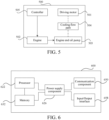
- An embodiment of the present disclosure further provides a vehicle 500, as shown in FIG. 5 , including a driving motor 501, an engine 502, an engine end oil pump 503, a cooling flow path 504, and a controller 505.
- the engine 502 is configured to drive the engine end oil pump 503 to run.
- the cooling flow path 504 connects the engine end oil pump 503 to the driving motor 501.
- the controller 505 is configured to implement the steps of the method for cooling a locked rotor driving motor of a vehicle according to the above embodiments.
- An embodiment of the present disclosure further provides a vehicle, including:
- FIG. 6 is a block diagram illustrating another vehicle 600 according to an example embodiment.
- the vehicle 600 includes one or more processors 622, and a memory 632 configured to store a computer program executable by the processor 622.
- the computer program stored in the memory 632 may include one or more modules each corresponding to a set of instructions.
- the processor 622 may be configured to execute the computer program, to perform the method for cooling a driving motor described above.
- the vehicle 600 may further include a power supply component 626 and a communication component 660.
- the power supply component 626 may be configured to perform power management of the vehicle 600.
- the communication component 660 may be configured to implement communication of the vehicle 600, such as wired or wireless communication.
- the vehicle 600 may further include an input/output (I/O) interface 668.
- the vehicle 600 may operate based on an operating system stored in the memory 632, such as Windows ServerTM, Mac OS XTM, UnixTM, and LinuxTM.
- a computer-readable storage medium including program instructions is further provided.
- the program instructions when executed by a processor, implement the steps of the method for cooling a driving motor described above.
- the non-transitory computer-readable storage medium may be the above-mentioned memory 632 including program instructions, and the above-mentioned program instructions may be executed by the processor 622 of the vehicle 600 to complete the method for cooling a driving motor described above.
- a computer program product includes a computer program executable by a programmable device.
- the computer program has a code portion for performing the method for cooling a locked rotor driving motor of a vehicle described above when executed by the programmable device.
Landscapes
- Engineering & Computer Science (AREA)
- Chemical & Material Sciences (AREA)
- Combustion & Propulsion (AREA)
- Transportation (AREA)
- Mechanical Engineering (AREA)
- Automation & Control Theory (AREA)
- Electric Propulsion And Braking For Vehicles (AREA)
- Hybrid Electric Vehicles (AREA)
- Motor Or Generator Cooling System (AREA)
- Control Of Vehicle Engines Or Engines For Specific Uses (AREA)
- Auxiliary Drives, Propulsion Controls, And Safety Devices (AREA)
Abstract
Description
- The present disclosure claims priority to
Chinese Patent Application No. 202210188260.0, filed on February 28, 2022 - The present disclosure relates to the field of vehicle heat dissipation, and specifically, to a method and device for cooling a locked rotor driving motor of a vehicle and a vehicle.
- For a hybrid vehicle equipped with an electric oil pump, a cooling system is driven by the electric oil pump, and can cool a driving motor under full working conditions. However, for a hybrid vehicle without an electric oil pump, when the vehicle is in an electric vehicle mode, the cooling of the driving motor mainly depends on rotation of a wheel to drive a wheel end oil pump to perform a cooling operation. However, when the hybrid vehicle is in an electric vehicle mode, a locked rotor of the driving motor may lead to a low vehicle speed, and then the wheel end oil pump has a low rotational speed to make it impossible to provide a sufficient coolant to cool the driving motor. As a result, the service life of the driving motor is reduced or the driving motor is even burnt out.
- An objective of the present disclosure is to provide a method and device for cooling a locked rotor driving motor of a vehicle and a vehicle, to solve the technical problem that when a locked rotor occurs to a driving motor in an electric vehicle mode, it is impossible to provide a sufficient coolant to cool the driving motor.
- In order to achieve the above objective, a first aspect of the present disclosure provides a method for cooling a locked rotor driving motor of a vehicle. The vehicle includes a driving motor, an engine, an engine end oil pump, and a cooling flow path. The engine is configured to drive the engine end oil pump to run, and the cooling flow path connects the engine end oil pump to the driving motor. The method includes the following:
- If a driving mode of the vehicle is an electric vehicle mode, the vehicle meets a preset locked rotor motor activation condition, and a current temperature of the driving motor is greater than an auxiliary cooling starting temperature of the engine, the engine of the vehicle is controlled to start, to cause the engine end oil pump of the vehicle to drive a coolant in the cooling flow path to cool the driving motor.
- Optionally, the method further includes the following:
- First duration for a temperature of the driving motor to reach a first preset temperature is determined according to a temperature change rate of the driving motor and the current temperature of the driving motor; and
- if the first duration is less than or equal to first preset duration, the auxiliary cooling starting temperature of the engine is reduced.
- Optionally, that if the first duration is less than or equal to first preset duration, the auxiliary cooling starting temperature of the engine is reduced includes the following:
- If the first duration is less than or equal to the first preset duration, a target correction offset is determined based on the temperature change rate of the driving motor and a preset relationship between the temperature change rate and a correction offset; and
- a difference between the first preset temperature and the target correction offset is taken as the auxiliary cooling starting temperature of the engine.
- Optionally, that if the first duration is less than or equal to first preset duration, the auxiliary cooling starting temperature of the engine is reduced includes the following:
If the first duration is less than or equal to first preset duration, the auxiliary cooling starting temperature of the engine is equal to a second preset temperature, where the second preset temperature is less than the first preset temperature. - Optionally, the method further includes the following:
If the first duration is greater than the first preset duration, the auxiliary cooling starting temperature of the engine is equal to the first preset temperature. - Optionally, the method further includes the following:
If the vehicle meets a preset locked rotor motor exit condition and it is determined that the current temperature of the driving motor is less than an auxiliary cooling shutdown temperature of the engine, the engine is controlled to stop running after second preset duration. - Optionally, the first preset temperature is a maximum allowable temperature of the driving motor, the second preset temperature is a safe starting temperature of the driving motor under a locked rotor working condition, and the auxiliary cooling starting temperature of the engine is less than or equal to the first preset temperature.
- Optionally, the method further includes the following:
- A rotational speed of the engine is controlled based on the current temperature of the driving motor, where the rotational speed of the engine is positively correlated with the current temperature of the driving motor; and
- if the vehicle meets the preset locked rotor motor activation condition and a flow rate of flowing through the cooling flow path of the driving motor is greater than a first preset cooling flow rate, a cooling fan of the vehicle is controlled to run at a maximum rotational speed to cool the driving motor.
- Optionally, the method further includes the following:
- If the vehicle meets a preset locked rotor motor exit condition and a flow rate of flowing through the cooling flow path of the driving motor is less than a second preset cooling flow rate, the cooling fan is controlled to stop running,
- where the first preset cooling flow rate is greater than the second preset cooling flow rate.
- Optionally, that the engine of the vehicle is controlled to start includes the following:
- The engine is controlled to output a preset rotational speed; and
- a cooling fan of the vehicle is controlled to run at a maximum rotational speed to cool the driving motor.
- Optionally, the method further includes the following:
- It is determined that the vehicle meets a preset locked rotor motor exit condition and it is determined that the current temperature of the driving motor is less than an auxiliary cooling shutdown temperature of the engine; and
- the cooling fan is controlled to stop running, and the engine is controlled to stop running after second preset duration; or the engine and the cooling fan are controlled to stop running after the second preset duration.
- Optionally, the preset locked rotor motor activation condition includes: a gear of the vehicle is in a forward gear or a reverse gear, a torque of the driving motor is greater than or equal to a first preset torque, and a vehicle speed of the vehicle is less than or equal to a first preset vehicle speed; and
- the preset locked rotor motor exit condition includes one or more of the following: the gear of the vehicle is neither in the forward gear nor in the reverse gear, the torque of the driving motor is less than a second preset torque, and the vehicle speed of the vehicle is greater than or equal to a second preset vehicle speed,
- where the first preset torque is greater than the second preset torque, and the first preset vehicle speed is less than the second preset vehicle speed.
- Optionally, the vehicle includes a spill valve, and the spill valve is configured to control a flow rate in the cooling flow path. The method further includes the following:
After the engine is started to cool the driving motor, if the flow rate of flowing through the cooling flow path of the driving motor is greater than a third preset cooling flow rate, the spill valve of the vehicle is requested to enter a forcibly closed state. - A second aspect of the present disclosure further provides a device for cooling a locked rotor driving motor of a vehicle. The vehicle includes a driving motor, an engine, an engine end oil pump, and a cooling flow path. The engine is configured to drive the engine end oil pump to run, and the cooling flow path connects the engine end oil pump to the driving motor. The device includes:
a controller, configured to implement the steps of the method for cooling a locked rotor driving motor of a vehicle according to any one of the implementations of the first aspect described above. - A third aspect of the present disclosure further provides a non-transitory computer-readable storage medium, having a computer program stored thereon. The program, when executed by a processor, implements the steps of the method for cooling a locked rotor driving motor of a vehicle according to any one of the implementations of the first aspect described above.
- A fourth aspect of the present disclosure further provides a vehicle, including a driving motor, an engine, an engine end oil pump, a cooling flow path, and a controller.
- The engine is configured to drive the engine end oil pump to run.
- The cooling flow path connects the engine end oil pump to the driving motor.
- The controller is configured to implement the steps of the method for cooling a locked rotor driving motor of a vehicle according to any one of the implementations of the first aspect described above.
- Through the above technical solutions, at least the following technical effects can be achieved:
If a driving mode of the vehicle is an electric vehicle mode, the vehicle meets a preset locked rotor motor activation condition, and a current temperature of the driving motor is greater than an auxiliary cooling starting temperature of the engine, the engine of the vehicle is controlled to start, to cause the engine end oil pump of the vehicle to drive a coolant in the cooling flow path to cool the driving motor. By this method, when the vehicle is in the electric vehicle mode and a locked rotor occurs to the driving motor, the engine of the vehicle can be started to cool the driving motor, thereby solving the problem that the locked rotor of the driving motor leads to a low rotational speed of the wheel end oil pump to make it impossible to provide a sufficient coolant to cool the driving motor. As a result, the service life of the driving motor is reduced or the driving motor is even burnt out. - Other features and advantages of the present disclosure are described in detail in the subsequent specific implementations.
- Accompanying drawings are intended to provide a further understanding of the present disclosure, and constitute a part of the specification. The accompanying drawings, together with the following specific implementations, are intended to explain the present disclosure, but do not constitute a limitation on the present disclosure. In the drawings:
-
FIG. 1 is a schematic diagram of a cooling system architecture; -
FIG. 2 is a schematic flowchart of a method for cooling a locked rotor driving motor of a vehicle according to an embodiment of the present disclosure; -
FIG. 3 is a schematic flowchart of another method for cooling a locked rotor driving motor of a vehicle according to an embodiment of the present disclosure; -
FIG. 4 is a block diagram of a device for cooling a locked rotor driving motor of a vehicle according to an embodiment of the present disclosure; -
FIG. 5 is a block diagram of a wheel according to an embodiment of the present disclosure; and -
FIG. 6 is a block diagram of another wheel according to an embodiment of the present disclosure. - Specific implementations of the present disclosure are described in detail below with reference to the accompanying drawings. It should be understood that the specific implementations described herein are merely intended to illustrate and explain the present disclosure, and are not intended to limit the present disclosure.
- It should be understood that the steps described in the method implementations of the present disclosure may be performed in different orders and/or in parallel. In addition, the method implementation may include additional steps and/or omit the steps shown. The scope of the present disclosure is not limited in this respect. The term "include" and variants thereof used herein are open-ended including, that is, "including but not limited to". The term "based on" is "at least partially based on". The term "an embodiment" means "at least one embodiment". The term "another embodiment" means "at least one other embodiment". The term "some embodiments" means "at least some embodiments". Related definitions of other terms will be given in the following description.
- It should be noted that the concepts of "first", "second", and the like mentioned in the present disclosure are only intended to distinguish different devices, modules, or units, and are not intended to limit the order or interdependence of the functions performed by these devices, modules, or units. It should be noted that the modifications of "a" and "multiple" mentioned in the present disclosure are schematic rather than limiting, and those skilled in the art should understand that unless the context clearly indicates otherwise, they should be understood as "one or more".
- Currently, a cooling system architecture of a hybrid vehicle without an electric oil pump is shown in
FIG. 1 . A wheelend oil pump 101 and an engineend oil pump 102 are mechanical pumps. The wheelend oil pump 101 is driven by rotation of a wheel and is responsible for a low-pressure oil circuit (cooling and lubrication), while the engineend oil pump 102 is driven by rotation of an engine and is responsible for oil supply of a high-pressure oil circuit (hydraulic pressure of a clutch 108, and the like). In addition, acontrol valve 103 is arranged between the low-pressure oil circuit and the high-pressure oil circuit, and thecontrol valve 103 includes at least a first state in which the engineend oil pump 102 is allowed to supply oil to a cooling oil circuit of a drivingmotor 104 and a second state in which the oil supply is off. When the hybrid vehicle is in an electric vehicle mode, the wheelend oil pump 101 is driven to perform a cooling operation mainly by the rotation of a wheel. When the hybrid vehicle is in a hybrid mode, the engineend oil pump 102 is driven by the engine to perform a cooling operation with the wheelend oil pump 101. In addition, a coolingfan 105 can also cool the drivingmotor 104 when operating. Aspill valve 106 is an electromagnetic valve that controls a cooling flow rate of the cooling oil circle. When the drivingmotor 104 does not need cooling, thespill valve 106 is opened, allowing only cooling oil (that is, coolant) with a minimum flow rate to flow to the drivingmotor 104, and the excess part flows back to anoil tank 107. The drivingmotor 104 is shut down when needing to be cooled, and all the cooling oil exchanges heat with the outside through the cooling oil circuit. - However, when the hybrid vehicle is in an electric vehicle mode, a locked rotor of the driving motor may lead to a low vehicle speed, and then the wheel end oil pump has a low rotational speed to make it impossible to provide a sufficient coolant to cool the driving motor. As a result, the service life of the driving motor is reduced or the driving motor is even burnt out.
- In view of this, for a hybrid vehicle without an electric oil pump, the present disclosure provides a method and device for cooling a locked rotor driving motor of a vehicle and a vehicle, to solve the above problems.
- The technical solution of the present disclosure is described in detail below with reference to embodiments.
- An embodiment of the present disclosure provides a method for cooling a locked rotor driving motor of a vehicle. The vehicle includes a driving motor, an engine, an engine end oil pump, and a cooling flow path. The engine is configured to drive the engine end oil pump to run, and the cooling flow path connects the engine end oil pump to the driving motor. As shown in
FIG. 2 , the method includes the following steps. - S201: If a driving mode of the vehicle is an electric vehicle mode, the vehicle meets a preset locked rotor motor activation condition, and a current temperature of the driving motor is greater than an auxiliary cooling starting temperature of the engine, the engine of the vehicle is controlled to start, to cause the engine end oil pump of the vehicle to drive a coolant in the cooling flow path to cool the driving motor.
- By means of the above method, if a driving mode of the vehicle is an electric vehicle mode, the vehicle meets a preset locked rotor motor activation condition, and a current temperature of the driving motor is greater than an auxiliary cooling starting temperature of the engine, the engine of the vehicle is controlled to start, to cause the engine end oil pump of the vehicle to drive a coolant in the cooling flow path to cool the driving motor. By this method, when the vehicle is in the electric vehicle mode and a locked rotor occurs to the driving motor, the engine of the vehicle can be started to cool the driving motor, thereby solving the problem that the locked rotor of the driving motor leads to a low rotational speed of the wheel end oil pump to make it impossible to provide a sufficient coolant to cool the driving motor. As a result, the service life of the driving motor is reduced or the driving motor is even burnt out.
- To make those skilled in the art better understand the method for cooling a locked rotor driving motor of a vehicle according to the present disclosure, the above steps are illustrated in detail below.
- In a possible implementation, the method further includes the following: First duration for a temperature of the driving motor to reach a first preset temperature is determined according to a temperature change rate of the driving motor and the current temperature of the driving motor; and if the first duration is less than or equal to first preset duration, the auxiliary cooling starting temperature of the engine is reduced.
- For example, if the first duration is less than or equal to the first preset duration, the auxiliary cooling starting temperature of the engine being reduced may be as follows: If the first duration is less than or equal to the first preset duration, a target correction offset is determined based on the temperature change rate of the driving motor and a preset relationship between the temperature change rate and a correction offset, and then a difference between the first preset temperature and the target correction offset is taken as the auxiliary cooling starting temperature of the engine.
- Alternatively, if the first duration is less than or equal to first preset duration, the auxiliary cooling starting temperature of the engine being reduced may be as follows: If the first duration is less than or equal to first preset duration, the auxiliary cooling starting temperature of the engine is equal to a second preset temperature, where the second preset temperature is less than the first preset temperature.
- The first preset temperature is a maximum allowable temperature of the driving motor, the second preset temperature is a safe starting temperature of the driving motor under a locked rotor working condition, and the auxiliary cooling starting temperature of the engine is less than or equal to the first preset temperature.
- It should be understood that under normal circumstances, the auxiliary cooling starting temperature of the engine is usually set to a maximum allowable temperature of the driving motor. However, due to a response delay of a temperature sensor for a certain time, when the temperature sensor detects that the current temperature of the driving motor is greater than the maximum allowable temperature, an actual temperature of the driving motor may have been already much greater than the maximum allowable temperature, leading to overheating and burning of the driving motor. Therefore, the auxiliary cooling starting temperature of the engine can be adjusted according to the current temperature change rate and the maximum allowable temperature of the driving motor. For example, the auxiliary cooling starting temperature of the engine can be reduced, so that the engine can be started in advance to participate in the cooling of the driving motor, thereby ensuring that the driving motor always operates in a reasonable temperature range and avoiding overheating and burning of the driving motor caused by the response delay of the temperature sensor.
- For example, the preset relationship between the temperature change rate and the correction offset is determined by experiments, which may be shown in Table 1 below. The temperature change rate is a temperature change rate of the driving motor every 3 seconds, and is obtained by rounding.
Table 1 Temperature change rate (°C/3 s) 0 1 2 3 Correction offset A (°C) 0 10 20 30 - The auxiliary cooling starting temperature of the engine may be determined by the following calculation formula:

where T denotes the auxiliary cooling starting temperature of the engine, T0 denotes the maximum allowable temperature of the driving motor, and A denotes the correction offset. The correction offset can be obtained by querying the current temperature change rate detected by the temperature sensor in Table 1. - Alternatively, based on the safe starting temperature of the driving motor under a locked rotor working condition, when the first duration is less than or equal to the first preset duration, the auxiliary cooling starting temperature of the engine is set to the safe starting temperature (second preset temperature), so that the engine can be started in advance to participate in the cooling of the driving motor, thereby ensuring that the driving motor always operates in a reasonable temperature range and avoiding overheating and burning of the driving motor caused by the response delay of the temperature sensor. Optionally, a relationship curve of the current temperature change rate and the auxiliary cooling starting temperature of the engine may be determined by experiments. In the relationship curve, when the current temperature change rate is 0, the auxiliary cooling starting temperature of the engine is equal to the maximum allowable temperature of the driving motor, and a larger current temperature change rate indicates a smaller auxiliary cooling starting temperature of the engine. The auxiliary cooling starting temperature of the engine is reduced based on the relationship curve, and the engine can be started in advance to cool the driving motor, to ensure that the driving motor always operates in a reasonable temperature range and avoid overheating and burning of the driving motor caused by the response delay of the temperature sensor.
- In a possible implementation, the method further includes the following: If the first duration is greater than the first preset duration, the auxiliary cooling starting temperature of the engine is equal to the first preset temperature.
- That is, when the duration for the temperature of the driving motor to reach the maximum allowable temperature is greater than the first preset duration, the driving motor is currently subjected to no risk of overheating and burning. Therefore, it is not necessary to start the engine in advance to participate in the cooling of the driving motor, and the auxiliary cooling starting temperature of the engine may be set to be consistent with the maximum allowable temperature. When the duration for the temperature of the driving motor to reach the maximum allowable temperature is less than or equal to the first preset duration, the driving motor is currently subjected to the risk of overheating and burning. Therefore, it is necessary to start the engine in advance to participate in the cooling of the driving motor, and the auxiliary cooling starting temperature of the engine is reduced to ensure that the driving motor always operates in a reasonable temperature range, and avoid overheating and burning of the driving motor caused by the response delay of the temperature sensor. The safe starting temperature may be 80°C and the maximum allowable temperature may be 110°C, which is specifically determined according to physical characteristics of the driving motor, and is not specifically limited in the present disclosure. In a possible implementation, the method further includes the following: If the vehicle meets a preset locked rotor motor exit condition and it is determined that the current temperature of the driving motor is less than an auxiliary cooling shutdown temperature of the engine, the engine is controlled to stop running after second preset duration.
- For example, when the vehicle meets the preset locked rotor motor activation condition, the vehicle meets a preset cooling exit condition, and the current temperature of the driving motor is greater than the auxiliary cooling starting temperature of the engine, the engine is immediately started to participate in the cooling of the driving motor to avoid overheating and burning of the driving motor. Then, when the vehicle meets the preset cooling exit condition and it is determined that the current temperature of the driving motor is less than the auxiliary cooling shutdown temperature of the engine, that is, when the driving motor no longer needs the engine to participate in cooling, to avoid the loss caused by frequent starting of the engine to the engine, the engine can be shut down after preset duration, so as to prevent a change in vehicle state in a short time, which otherwise results in restarting the engine to cool the driving motor. The auxiliary cooling shutdown temperature of the engine is determined according to the physical characteristics of the driving motor, and for example, may be 105°C, and the preset duration may be set according to experiments, and for example, may be 14 s, which is not limited in the present disclosure.
- In a possible implementation, the method further includes the following: A rotational speed of the engine is controlled based on the current temperature of the driving motor. The rotational speed of the engine is positively correlated with the current temperature of the driving motor. If the vehicle meets the preset locked rotor motor activation condition and a flow rate of flowing through the cooling flow path of the driving motor is greater than a first preset cooling flow rate, a cooling fan of the vehicle is controlled to run at a maximum rotational speed to cool the driving motor.
- Further, the method further includes the following: If the vehicle meets a preset locked rotor motor exit condition and a flow rate of flowing through the cooling flow path of the driving motor is less than a second preset cooling flow rate, the cooling fan is controlled to stop running. The first preset cooling flow rate is greater than the second preset cooling flow rate.
- It should be noted that the cooling of the driving motor mainly depends on that the coolant circulates in the cooling flow path, thereby taking away heat generated by the driving motor during the operation, and exchanging heat with the outside through a heat dissipation system.
- For example, the rotational speed of the engine is positively correlated with the current temperature of the driving motor, that is, when the current temperature of the driving motor is higher, faster heat dissipation is needed, so the rotational speed of the engine controlled is higher, and a cooling flow rate driven by the engine end oil pump is larger, thereby taking away more heat. In addition, if the vehicle meets the preset locked rotor motor activation condition and a flow rate of flowing through the cooling flow path of the driving motor is greater than a first preset cooling flow rate, a cooling fan of the vehicle is controlled to run at a maximum rotational speed to ensure that the coolant dissipates heat as soon as possible, thereby cooling the driving motor.
- However, if the vehicle meets the preset locked rotor motor exit condition and the flow rate of flowing through the cooling flow path of the driving motor is less than the second preset cooling flow rate, the cooling fan is controlled to stop running. Unnecessary energy consumption caused by the cooling fan always running at the maximum rotational speed is avoided.
- The first preset cooling flow rate and the second preset cooling flow rate may be determined through experiments. For example, the first preset cooling flow rate may be 3 L, and the second preset cooling flow rate may be 1.5 L, which is not specifically limited in the present disclosure, provided that it is ensured that the first preset cooling flow rate is greater than the second preset cooling flow rate.
- In a possible implementation, the engine start of the vehicle may be controlled by the following method: The engine is controlled to output a preset rotational speed, and the cooling fan of the vehicle is controlled to run at a maximum rotational speed to cool the driving motor.
- Further, the method further includes the following: It is determined that the vehicle meets the preset locked rotor motor exit condition, it is determined that the current temperature of the driving motor is less than the auxiliary cooling shutdown temperature of the engine, then the cooling fan is controlled to stop running, and the engine is controlled to stop running after second preset duration. Alternatively, the engine and the cooling fan are controlled to stop running after second preset duration.
- That is, if a driving mode of the vehicle is an electric vehicle mode, the vehicle meets the preset locked rotor motor activation condition, and the current temperature of the driving motor is greater than the auxiliary cooling starting temperature of the engine, the engine is controlled to run at a preset rotational speed to drive the engine end oil pump, and the cooling fan of the vehicle is controlled to run at the maximum rotational speed to cool the driving motor. The preset rotational speed is determined through experiments with both heat dissipation requirements and energy saving requirements taken into account, so as to better cool the driving motor.
- Further, when the vehicle meets the preset locked rotor motor exit condition and the current temperature of the driving motor is less than the auxiliary cooling shutdown temperature of the engine, the cooling fan may be controlled to stop running, and the engine is controlled to stop running after the second preset duration. Alternatively, when the vehicle meets the preset locked rotor motor exit condition and the current temperature of the driving motor is less than the auxiliary cooling shutdown temperature of the engine, the engine and the cooling fan may be controlled to stop running after the second preset duration, to avoid unnecessary energy consumption. The second preset duration may be set as required, which is not limited in the present disclosure.
- In a possible implementation, the vehicle includes a spill valve, and the spill valve is configured to control a flow rate in the cooling flow path. The method further includes the following: After the engine is started to cool the driving motor, if the flow rate of flowing through the cooling flow path of the driving motor is greater than a third preset cooling flow rate, the spill valve of the vehicle is requested to enter a forcibly closed state.
- For example, after the engine is started to cool the driving motor, if the flow rate of flowing through the cooling flow path of the driving motor is greater than the third preset cooling flow rate, the spill valve of the vehicle is requested to enter a forcibly closed state, so that all the coolant passes through the cooling flow path of the vehicle to cool the driving motor, thereby improving the cooling effect on the driving motor. Then, if the vehicle meets the above preset locked rotor motor exit condition or the flow rate in the cooling flow path is less than the preset flow rate upon the opening of the spill valve, the spill valve is requested to exit the forcibly closed state, so as to reduce unnecessary power consumption.
- It should be noted that closing the spill valve requires power-on control, which causes a resistor therein to heat up continuously. Therefore, if the spill valve is controlled to be closed when the engine is just started, that is, when the flow rate in the cooling flow path is low, the spill valve quickly heats up and is burned out. Therefore, in the embodiment of the present disclosure, after the engine is started to cool the driving motor, the spill valve of the vehicle is requested to enter the forcibly closed state, to prevent the spill valve from being burnt out. Therefore, after the engine is started to cool the driving motor, the spill valve of the vehicle may be controlled based on whether the flow rate of the cooling flow path meets preset requirements. For example, the spill valve may be controlled to be closed when the flow rate of the cooling flow path is greater than 1.5 L, and after the spill valve is closed, the spill valve may be controlled to be opened when the flow rate in the cooling flow path is less than 3 L, which may be specifically set as required, and is not limited in the present disclosure.
- In a possible implementation, the preset locked rotor motor activation condition includes: a gear of the vehicle is in a forward gear or a reverse gear, a torque of the driving motor is greater than or equal to a first preset torque, and a vehicle speed of the vehicle is less than or equal to a first preset vehicle speed. The preset locked rotor motor exit condition includes one or more of the following: the gear of the vehicle is neither in the forward gear nor in the reverse gear, the torque of the driving motor is less than a second preset torque, and the vehicle speed of the vehicle is greater than or equal to a second preset vehicle speed. The first preset torque is greater than the second preset torque, and the first preset vehicle speed is less than the second preset vehicle speed.
- For example, the first preset torque, the first preset vehicle speed, and the first preset temperature may be determined according to experiments and physical characteristics of the vehicle. For example, the first preset torque may be 150 N·m and the first preset vehicle speed may be 3 KM/h, which is not specifically limited in the present disclosure. The second preset torque, the second preset vehicle speed, and the second preset temperature are determined according to experiments and physical characteristics of the vehicle. For example, the second preset torque may be 10 N·m and the second preset vehicle speed may be 5 KM/h, which is not specifically limited in the present disclosure.
- For example, when the vehicle is in the electric vehicle mode, and the vehicle meets requirements for a gear of the vehicle being in the forward gear or the reverse gear, the torque of the driving motor being greater than or equal to the first preset torque, the current vehicle speed of the vehicle being less than or equal to the first preset vehicle speed, and the current temperature of the driving motor being greater than the auxiliary cooling starting temperature of the engine, it can be determined that the driving motor of the vehicle is in a locked rotor state and needs to be cooled, and then the engine is started, so that the engine end oil pump of the vehicle drives the coolant in the cooling flow path to cool the driving motor. As a result, the service life of the driving motor is reduced or the driving motor is even burnt out. Then, when the vehicle meets the preset locked rotor motor exit condition, that is, when the driving motor no longer needs the engine to participate in cooling, to avoid the loss caused by frequent starting of the engine to the engine, the engine may be shut down after preset duration.
- Further, when the current vehicle speed is greater than the first preset vehicle speed and less than the second preset vehicle speed, or when the torque of the driving motor is less than the first preset torque and greater than the second preset torque, the engine may be kept in the current operating state, so as to reduce the impact of vehicle speed fluctuation or torque fluctuation on the operating state of the engine and avoid the loss caused by frequent starting of the engine to the engine.
- To make those skilled in the art understand the method according to the embodiment of the present disclosure more easily, the steps of the method for cooling a locked rotor driving motor of a vehicle are described in detail below. As shown in
FIG. 3 , the method includes the following steps. - S301: It is determined that a driving mode of the vehicle is an electric vehicle mode, and it is determined that the vehicle meets a preset locked rotor motor activation condition and a current temperature of the driving motor is greater than an auxiliary cooling starting temperature of an engine.
- Step S302: The engine of the vehicle is started.
- S303: It is determined whether a flow rate in a cooling flow path is greater than a first preset cooling flow rate.
- Further, if the flow rate in the cooling flow path is greater than the first preset cooling flow rate, step S304 is performed, or else step S308 is performed.
- S304: A cooling fan of the vehicle is requested to run at a maximum rotational speed.
- S305: It is determined whether the flow rate in the cooling flow path is greater than a third preset cooling flow rate.
- Further, if the flow rate in the cooling flow path is greater than the third preset cooling flow rate, step S306 is performed, or else step S310 is performed.
- S306: A spill valve of the vehicle is requested to enter a forcibly closed state.
- S307: It is determined whether the vehicle meets any preset locked rotor motor exit condition and whether the flow rate in the cooling flow path is less than a second preset cooling flow rate.
- Further, if the vehicle meets any preset locked rotor motor exit condition and the flow rate in the cooling flow path is less than the second preset cooling flow rate, step S308 is performed, otherwise step S304 is performed.
- S308: The cooling fan of the vehicle is requested to stop running.
- S309: It is determined whether the vehicle meets any preset locked rotor motor exit condition or whether the flow rate in the cooling flow path is less than an opening flow rate.
- Further, if the vehicle meets any preset locked rotor motor exit condition or the flow rate in the cooling flow path is less than the opening flow rate, step S310 is performed, otherwise step S306 is performed.
- S310: The spill valve of the vehicle is requested to be opened.
- S311: It is determined whether the vehicle meets any preset locked rotor motor exit condition and it is determined that the current temperature of the driving motor is less than an auxiliary cooling shutdown temperature of the engine.
- Further, if the vehicle meets any preset locked rotor motor exit condition and it is determined that the current temperature of the driving motor is less than the auxiliary cooling shutdown temperature of the engine, step S312 is performed, or else the engine is kept in a started state.
- S312: The engine is shut down after preset duration.
- By the method, the engine of the vehicle can be started when the vehicle is in the electric vehicle mode and a locked rotor occurs to the driving motor, so that the engine end oil pump of the vehicle drives the coolant in the cooling flow path to cool the driving motor, so as to solve the problem that the locked rotor of the driving motor leads to a low rotational speed of the wheel end oil pump to make it impossible to provide a sufficient coolant to cool the driving motor. As a result, the service life of the driving motor is reduced or the driving motor is even burnt out. Furthermore, the heat exchange with the outside is accelerated by controlling the cooling fan and the spill valve, so as to improve the cooling effect on the driving motor.
- Based on the same inventive concept, the present disclosure further provides a device for cooling a locked rotor driving motor of a vehicle. The vehicle includes a driving motor, an engine, an engine end oil pump, and a cooling flow path. The engine is configured to drive the engine end oil pump to run, and the cooling flow path connects the engine end oil pump to the driving motor. As shown in
FIG. 4 , thedevice 400 includes:
acontroller 401, configured to implement the steps of the method for cooling a locked rotor driving motor of a vehicle described above. - Optionally, the
controller 401 is configured to:
control, if a driving mode of the vehicle is an electric vehicle mode, the vehicle meets a preset locked rotor motor activation condition, and a current temperature of the driving motor is greater than an auxiliary cooling starting temperature of the engine, the engine of the vehicle to start, to cause the engine end oil pump of the vehicle to drive a coolant in the cooling flow path to cool the driving motor. - Optionally, the
controller 401 is further configured to: - determine first duration for a temperature of the driving motor to reach a first preset temperature according to a temperature change rate of the driving motor and the current temperature of the driving motor; and
- reduce the auxiliary cooling starting temperature of the engine if the first duration is less than or equal to first preset duration.
- Optionally, the
controller 401 is further configured to: - determine, if the first duration is less than or equal to the first preset duration, a target correction offset based on the temperature change rate of the driving motor and a preset relationship between the temperature change rate and a correction offset; and
- take a difference between the first preset temperature and the target correction offset as the auxiliary cooling starting temperature of the engine.
- Optionally, the
controller 401 is further configured so that
if the first duration is less than or equal to first preset duration, the auxiliary cooling starting temperature of the engine is equal to a second preset temperature, where the second preset temperature is less than the first preset temperature. - Optionally, the
controller 401 is further configured so that
if the first duration is greater than the first preset duration, the auxiliary cooling starting temperature of the engine is equal to the first preset temperature. - Optionally, the
controller 401 is further configured to:
control, if the vehicle meets a preset locked rotor motor exit condition and it is determined that the current temperature of the driving motor is less than an auxiliary cooling shutdown temperature of the engine, the engine to stop running after second preset duration. - Optionally, the first preset temperature is a maximum allowable temperature of the driving motor, the second preset temperature is a safe starting temperature of the driving motor under a locked rotor working condition, and the auxiliary cooling starting temperature of the engine is less than or equal to the first preset temperature.
- Optionally, the
controller 401 is further configured to: - control a rotational speed of the engine based on the current temperature of the driving motor, where the rotational speed of the engine is positively correlated with the current temperature of the driving motor; and
- control, if the vehicle meets the preset locked rotor motor activation condition and a flow rate of flowing through the cooling flow path of the driving motor is greater than a first preset cooling flow rate, a cooling fan of the vehicle to run at a maximum rotational speed to cool the driving motor.
- Optionally, the
controller 401 is further configured to: - control, if the vehicle meets a preset locked rotor motor exit condition and a flow rate of flowing through the cooling flow path of the driving motor is less than a second preset cooling flow rate, the cooling fan to stop running,
- where the first preset cooling flow rate is greater than the second preset cooling flow rate.
- Optionally, the
controller 401 is configured to: - control the engine is to output a preset rotational speed; and
- control a cooling fan of the vehicle to run at a maximum rotational speed to cool the driving motor.
- Optionally, the
controller 401 is further configured to: - determine that the vehicle meets a preset locked rotor motor exit condition and determine that the current temperature of the driving motor is less than an auxiliary cooling shutdown temperature of the engine; and
- control the cooling fan to stop running, and control the engine to stop running after second preset duration; or control the engine and the cooling fan to stop running after second preset duration.
- Optionally, the preset locked rotor motor activation condition includes: a gear of the vehicle is in a forward gear or a reverse gear, a torque of the driving motor is greater than or equal to a first preset torque, and a vehicle speed of the vehicle is less than or equal to a first preset vehicle speed; and
- the preset locked rotor motor exit condition includes one or more of the following: the gear of the vehicle is neither in the forward gear nor in the reverse gear, the torque of the driving motor is less than a second preset torque, and the vehicle speed of the vehicle is greater than or equal to a second preset vehicle speed,
- where the first preset torque is greater than the second preset torque, and the first preset vehicle speed is less than the second preset vehicle speed.
- Optionally, the vehicle includes a spill valve, and the spill valve is configured to control a flow rate in the cooling flow path. The
controller 401 is further configured to:
request, after the engine is started to cool the driving motor, if the flow rate of flowing through the cooling flow path of the driving motor is greater than a third preset cooling flow rate, the spill valve of the vehicle to enter a forcibly closed state. - By the above device, when the vehicle is in the electric vehicle mode and a locked rotor occurs to the driving motor, the engine of the vehicle can be started to cool the driving motor, thereby solving the problem that the locked rotor of the driving motor leads to a low rotational speed of the wheel end oil pump to make it impossible to provide a sufficient coolant to cool the driving motor. As a result, the service life of the driving motor is reduced or the driving motor is even burnt out.
- With regard to the device in the above-mentioned embodiments, the specific way in which each module performs operations has been described in detail in the embodiments related to the method, and is not described in detail herein.
- An embodiment of the present disclosure further provides a non-transitory computer-readable storage medium, having a computer program stored thereon. The program, when executed by a processor, implements the steps of the method for cooling a locked rotor driving motor of a vehicle according to the above embodiments.
- An embodiment of the present disclosure further provides a
vehicle 500, as shown inFIG. 5 , including a drivingmotor 501, anengine 502, an engineend oil pump 503, acooling flow path 504, and acontroller 505. - The
engine 502 is configured to drive the engineend oil pump 503 to run. - The
cooling flow path 504 connects the engineend oil pump 503 to the drivingmotor 501. - The
controller 505 is configured to implement the steps of the method for cooling a locked rotor driving motor of a vehicle according to the above embodiments. - An embodiment of the present disclosure further provides a vehicle, including:
- a memory, having a computer program stored thereon; and
- a processor, configured to execute the computer program in the memory to implement the steps of the method for cooling a driving motor according to the above embodiments.
-
FIG. 6 is a block diagram illustrating anothervehicle 600 according to an example embodiment. Referring toFIG. 6 , thevehicle 600 includes one ormore processors 622, and amemory 632 configured to store a computer program executable by theprocessor 622. The computer program stored in thememory 632 may include one or more modules each corresponding to a set of instructions. In addition, theprocessor 622 may be configured to execute the computer program, to perform the method for cooling a driving motor described above. - In addition, the
vehicle 600 may further include apower supply component 626 and a communication component 660. Thepower supply component 626 may be configured to perform power management of thevehicle 600. The communication component 660 may be configured to implement communication of thevehicle 600, such as wired or wireless communication. In addition, thevehicle 600 may further include an input/output (I/O) interface 668. Thevehicle 600 may operate based on an operating system stored in thememory 632, such as Windows ServerTM, Mac OS XTM, UnixTM, and LinuxTM. - In another example embodiment, a computer-readable storage medium including program instructions is further provided. The program instructions, when executed by a processor, implement the steps of the method for cooling a driving motor described above. For example, the non-transitory computer-readable storage medium may be the above-mentioned
memory 632 including program instructions, and the above-mentioned program instructions may be executed by theprocessor 622 of thevehicle 600 to complete the method for cooling a driving motor described above. - In another example embodiment, a computer program product is further provided. The computer program product includes a computer program executable by a programmable device. The computer program has a code portion for performing the method for cooling a locked rotor driving motor of a vehicle described above when executed by the programmable device.
- The preferred implementations of the present disclosure have been described above in detail with reference to the accompanying drawings, but the present disclosure is not limited to the specific details in the above-mentioned implementations. Within the technical concept of the present disclosure, various simple modifications can be made to the technical solutions of the present disclosure, and these simple modifications all fall within the protection scope of the present disclosure.
- In addition, it should be noted that the specific technical features described in the above-mentioned specific implementations can be combined in any suitable way without contradiction. To prevent unnecessary repetition, various possible combinations are no longer explained separately in the present disclosure.
- In addition, various implementations of the present disclosure can also be arbitrarily combined, provided that they do not depart from the idea of the present disclosure, which should also be regarded as the contents disclosed in the present disclosure.
Claims (16)
- A method for cooling a locked rotor driving motor of a vehicle, the vehicle (500) comprising a driving motor (501), an engine (502), an engine end oil pump (503), and a cooling flow path (504), the engine (502) being configured to drive the engine end oil pump (503) to run, and the cooling flow path (504) connecting the engine end oil pump (503) to the driving motor (501), the method comprising:
controlling, if a driving mode of the vehicle (500) is an electric vehicle mode, the vehicle (500) meets a preset motor locked rotor activation condition, and a current temperature of the driving motor is greater than an auxiliary cooling starting temperature of the engine, the engine (502) of the vehicle (500) to start, to cause the engine end oil pump (503) of the vehicle (500) to drive a coolant in the cooling flow path (504) to cool the driving motor (501). - The method according to claim 1, further comprising:determining first duration for a temperature of the driving motor (501) to reach a first preset temperature according to a temperature change rate of the driving motor (501) and the current temperature of the driving motor (501); andreducing, if the first duration is less than or equal to first preset duration, the auxiliary cooling starting temperature of the engine.
- The method according to claim 2, wherein the reducing, if the first duration is less than or equal to first preset duration, the auxiliary cooling starting temperature of the engine comprises:determining, if the first duration is less than or equal to the first preset duration, a target correction offset based on the temperature change rate of the driving motor (501) and a preset relationship between the temperature change rate and a correction offset; andtaking a difference between the first preset temperature and the target correction offset as the auxiliary cooling starting temperature of the engine.
- The method according to claim 2, wherein the reducing, if the first duration is less than or equal to first preset duration, the auxiliary cooling starting temperature of the engine comprises:
allowing, if the first duration is less than or equal to first preset duration, the auxiliary cooling starting temperature of the engine to be equal to a second preset temperature, wherein the second preset temperature is less than the first preset temperature. - The method according to any one of claims 2 to 4, further comprising:
allowing, if the first duration is greater than the first preset duration, the auxiliary cooling starting temperature of the engine to be equal to the first preset temperature. - The method according to any one of claims 2 to 4, further comprising:
controlling, if the vehicle (500) meets a preset locked rotor motor exit condition and it is determined that the current temperature of the driving motor (501) is less than an auxiliary cooling shutdown temperature of the engine, the engine (502) to stop running after second preset duration. - The method according to any one of claims 2 to 4, wherein the first preset temperature is a maximum allowable temperature of the driving motor (501), the second preset temperature is a safe starting temperature of the driving motor (501) under a locked rotor working condition, and the auxiliary cooling starting temperature of the engine is less than or equal to the first preset temperature.
- The method according to claim 1, further comprising:controlling a rotational speed of the engine (502) based on the current temperature of the driving motor (501), wherein the rotational speed of the engine (502) is positively correlated with the current temperature of the driving motor (502); andcontrolling, if the vehicle (500) meets the preset locked rotor motor activation condition and a flow rate of flowing through the cooling flow path (504) of the driving motor (501) is greater than a first preset cooling flow rate, a cooling fan of the vehicle (500) to run at a maximum rotational speed to cool the driving motor (501).
- The method according to claim 8, further comprising:controlling, if the vehicle (500) meets a preset locked rotor motor exit condition and the flow rate of flowing through the cooling flow path (504) of the driving motor (501) is less than a second preset cooling flow rate, the cooling fan to stop running,wherein the first preset cooling flow rate is greater than the second preset cooling flow rate.
- The method according to claim 1, wherein the controlling the engine (502) of the vehicle (500) to start comprises:controlling the engine (502) to output a preset rotational speed; andcontrolling a cooling fan of the vehicle (500) to run at a maximum rotational speed to cool the driving motor (501).
- The method according to claim 10, further comprising:determining that the vehicle (500) meets a preset locked rotor motor exit condition and determining that the current temperature of the driving motor (501) is less than an auxiliary cooling shutdown temperature of the engine; andcontrolling the cooling fan to stop running, and controlling the engine (502) to stop running after second preset duration; or controlling the engine (502) and the cooling fan to stop running after second preset duration.
- The method according to claim 6 or 9 or 11, wherein the preset locked rotor motor activation condition comprises: a gear of the vehicle (500) is in a forward gear or a reverse gear, a torque of the driving motor (501) is greater than or equal to a first preset torque, and a vehicle speed of the vehicle (500) is less than or equal to a first preset vehicle speed; andthe preset locked rotor motor exit condition comprises one or more of the following: the gear of the vehicle is neither in the forward gear nor in the reverse gear, the torque of the driving motor is less than a second preset torque, and the vehicle speed of the vehicle (500) is greater than or equal to a second preset vehicle speed,wherein the first preset torque is greater than the second preset torque, and the first preset vehicle speed is less than the second preset vehicle speed.
- The method according to claim 1, wherein the vehicle (500) comprises a spill valve, the spill valve is configured to control a flow rate in the cooling flow path (504), and the method further comprises:
requesting, after the engine (502) is started to cool the driving motor (501), if a flow rate of flowing through the cooling flow path (504) of the driving motor (501) is greater than a third preset cooling flow rate, the spill valve of the vehicle (500) to enter a forcibly closed state. - A device for cooling a locked rotor driving motor of a vehicle, the vehicle (500) comprising a driving motor (501), an engine (502), an engine end oil pump (503), and a cooling flow path (504), the engine (502) being configured to drive the engine end oil pump (503) to run, and the cooling flow path (504) connecting the engine end oil pump (503) to the driving motor (501), the device comprising:
a controller (505), configured to implement the steps of the method for cooling a locked rotor driving motor of a vehicle according to any one of claims 1 to 13. - A non-transitory computer-readable storage medium, having a computer program stored thereon, wherein the program, when executed by a processor, implements the steps of the method for cooling a locked rotor driving motor of a vehicle according to any one of claims 1 to 13.
- Avehicle (500), comprising a driving motor (501), an engine (502), an engine end oil pump (503), a cooling flow path (504), and a controller (505);the engine (502) being configured to drive the engine end oil pump (503) to run;the cooling flow path (504) connecting the engine end oil pump (503) to the driving motor (501); andthe controller (505) being configured to implement the steps of the method for cooling a locked rotor driving motor of a vehicle according to any one of claims 1 to 13.
Applications Claiming Priority (2)
| Application Number | Priority Date | Filing Date | Title |
|---|---|---|---|
| CN202210188260.0A CN116691328B (en) | 2022-02-28 | 2022-02-28 | Method and device for cooling locked rotor of driving motor of vehicle and vehicle |
| PCT/CN2023/078005 WO2023160637A1 (en) | 2022-02-28 | 2023-02-23 | Drive motor stalling cooling method and apparatus for vehicle, and vehicle |
Publications (3)
| Publication Number | Publication Date |
|---|---|
| EP4438367A1 true EP4438367A1 (en) | 2024-10-02 |
| EP4438367A4 EP4438367A4 (en) | 2025-04-09 |
| EP4438367B1 EP4438367B1 (en) | 2026-01-21 |
Family
ID=87764851
Family Applications (1)
| Application Number | Title | Priority Date | Filing Date |
|---|---|---|---|
| EP23759259.7A Active EP4438367B1 (en) | 2022-02-28 | 2023-02-23 | Drive motor stalling cooling method and apparatus for vehicle, and vehicle |
Country Status (7)
| Country | Link |
|---|---|
| US (1) | US20240351574A1 (en) |
| EP (1) | EP4438367B1 (en) |
| JP (1) | JP7777231B2 (en) |
| KR (1) | KR20240112354A (en) |
| CN (1) | CN116691328B (en) |
| ES (1) | ES3061147T3 (en) |
| WO (1) | WO2023160637A1 (en) |
Families Citing this family (3)
| Publication number | Priority date | Publication date | Assignee | Title |
|---|---|---|---|---|
| CN117389346A (en) * | 2023-10-11 | 2024-01-12 | 中铁八局集团第一工程有限公司 | Temperature control device during concrete construction of abutment |
| KR20260027699A (en) | 2024-08-21 | 2026-03-03 | 주식회사 엘지에너지솔루션 | Apparatus For Processing of Pouch Type Battery Case and Pressing Method Using The Same |
| CN119953165B (en) * | 2025-01-17 | 2025-12-16 | 上汽通用五菱汽车股份有限公司 | A control method, device, vehicle, and storage medium for a vehicle cooling water pump. |
Family Cites Families (11)
| Publication number | Priority date | Publication date | Assignee | Title |
|---|---|---|---|---|
| JP3876793B2 (en) * | 2002-08-12 | 2007-02-07 | トヨタ自動車株式会社 | Multiple cooling system |
| JP4464984B2 (en) * | 2007-04-20 | 2010-05-19 | トヨタ自動車株式会社 | Vehicle oil supply device |
| FR2979080B1 (en) * | 2011-08-17 | 2013-08-16 | Renault Sa | COOLING SYSTEM FOR ELECTRIC PROPULSION VEHICLE |
| JP5781919B2 (en) * | 2011-12-28 | 2015-09-24 | トヨタ自動車株式会社 | Vehicle control system |
| JP2014000848A (en) * | 2012-06-15 | 2014-01-09 | Toyota Motor Corp | Rotary electric machine cooling system |
| CN109591602B (en) * | 2018-12-24 | 2020-10-13 | 浙江合众新能源汽车有限公司 | A system and method for blocking rotor protection of a drive motor of an electric vehicle |
| CN111022142A (en) * | 2019-12-31 | 2020-04-17 | 江门市大长江集团有限公司 | An oil cooling device for a hybrid powertrain, a hybrid vehicle and a motorcycle |
| CN111907512A (en) * | 2020-07-29 | 2020-11-10 | 一汽解放青岛汽车有限公司 | Cold start control method for hybrid vehicle and vehicle |
| CN114056109A (en) * | 2020-07-31 | 2022-02-18 | 广州汽车集团股份有限公司 | A method for improving automobile low temperature transmission efficiency and automobile electric drive system |
| CN213472768U (en) * | 2020-09-04 | 2021-06-18 | 弗迪动力有限公司 | Power assembly and vehicle |
| CN214450260U (en) * | 2021-03-04 | 2021-10-22 | 安徽华菱汽车有限公司 | Electrically-driven cooling system and range-extending type hybrid power agitating truck |
-
2022
- 2022-02-28 CN CN202210188260.0A patent/CN116691328B/en active Active
-
2023
- 2023-02-23 JP JP2024539760A patent/JP7777231B2/en active Active
- 2023-02-23 KR KR1020247021811A patent/KR20240112354A/en active Pending
- 2023-02-23 ES ES23759259T patent/ES3061147T3/en active Active
- 2023-02-23 WO PCT/CN2023/078005 patent/WO2023160637A1/en not_active Ceased
- 2023-02-23 EP EP23759259.7A patent/EP4438367B1/en active Active
-
2024
- 2024-06-28 US US18/759,757 patent/US20240351574A1/en active Pending
Also Published As
| Publication number | Publication date |
|---|---|
| US20240351574A1 (en) | 2024-10-24 |
| WO2023160637A1 (en) | 2023-08-31 |
| KR20240112354A (en) | 2024-07-18 |
| CN116691328A (en) | 2023-09-05 |
| CN116691328B (en) | 2024-08-06 |
| EP4438367A4 (en) | 2025-04-09 |
| JP2024547175A (en) | 2024-12-26 |
| ES3061147T3 (en) | 2026-03-31 |
| JP7777231B2 (en) | 2025-11-27 |
| EP4438367B1 (en) | 2026-01-21 |
Similar Documents
| Publication | Publication Date | Title |
|---|---|---|
| EP4438367A1 (en) | Drive motor stalling cooling method and apparatus for vehicle, and vehicle | |
| CN110356210B (en) | Temperature control device for vehicle | |
| JP2019156108A (en) | Temperature control device of vehicle | |
| US11892072B2 (en) | Method of managing the oil temperature of a transmission of a motor vehicle | |
| KR20200014539A (en) | Control method of cooling system for vehicle | |
| CN108026824A (en) | The cooling device of internal combustion engine for vehicle and the control method of cooling device | |
| KR102008605B1 (en) | Control method of electric oil pump | |
| KR20130017841A (en) | Water cooling type turbo charger system and operation method thereof | |
| JP2020006742A (en) | Vehicle heating system | |
| KR102030880B1 (en) | Fluid supply device | |
| WO2013112468A1 (en) | Method for controlling a vehicle engine | |
| CN113550819B (en) | A kind of engine warm-up control method and device | |
| JP2002213242A (en) | Moving object cooling control device | |
| US11028763B2 (en) | Engine cooling device | |
| CN111900833B (en) | Power motor heat management control method based on whole vehicle comprehensive control | |
| JP2019127201A (en) | Cooling device of vehicle | |
| KR20190000415A (en) | System and method for control of hybrid vehicle | |
| JP2012021422A (en) | Cooling device of on-vehicle internal combustion engine | |
| US20180135624A1 (en) | Oil supply device and method of controlling electric oil pump | |
| CN115158286B (en) | Hybrid power thermal management control system and method | |
| JP2015068257A (en) | Cooling device of engine | |
| JPH1024721A (en) | Heating system for vehicle | |
| JP2014070592A (en) | Control device | |
| JP2011226423A (en) | System for cooling vehicle driving device | |
| JP2025104840A (en) | Pump control method for vehicle coolant circulation system |
Legal Events
| Date | Code | Title | Description |
|---|---|---|---|
| STAA | Information on the status of an ep patent application or granted ep patent |
Free format text: STATUS: THE INTERNATIONAL PUBLICATION HAS BEEN MADE |
|
| PUAI | Public reference made under article 153(3) epc to a published international application that has entered the european phase |
Free format text: ORIGINAL CODE: 0009012 |
|
| STAA | Information on the status of an ep patent application or granted ep patent |
Free format text: STATUS: REQUEST FOR EXAMINATION WAS MADE |
|
| 17P | Request for examination filed |
Effective date: 20240628 |
|
| AK | Designated contracting states |
Kind code of ref document: A1 Designated state(s): AL AT BE BG CH CY CZ DE DK EE ES FI FR GB GR HR HU IE IS IT LI LT LU LV MC ME MK MT NL NO PL PT RO RS SE SI SK SM TR |
|
| A4 | Supplementary search report drawn up and despatched |
Effective date: 20250310 |
|
| RIC1 | Information provided on ipc code assigned before grant |
Ipc: H02K 9/19 20060101ALI20250304BHEP Ipc: H02K 9/00 20060101ALI20250304BHEP Ipc: B60K 11/02 20060101AFI20250304BHEP |
|
| DAV | Request for validation of the european patent (deleted) | ||
| DAX | Request for extension of the european patent (deleted) | ||
| GRAP | Despatch of communication of intention to grant a patent |
Free format text: ORIGINAL CODE: EPIDOSNIGR1 |
|
| STAA | Information on the status of an ep patent application or granted ep patent |
Free format text: STATUS: GRANT OF PATENT IS INTENDED |
|
| RIC1 | Information provided on ipc code assigned before grant |
Ipc: B60K 11/02 20060101AFI20250825BHEP Ipc: H02K 9/00 20060101ALI20250825BHEP Ipc: H02K 9/19 20060101ALI20250825BHEP |
|
| INTG | Intention to grant announced |
Effective date: 20250903 |
|
| GRAS | Grant fee paid |
Free format text: ORIGINAL CODE: EPIDOSNIGR3 |
|
| P01 | Opt-out of the competence of the unified patent court (upc) registered |
Free format text: CASE NUMBER: UPC_APP_0012693_4438367/2025 Effective date: 20251110 |
|
| GRAA | (expected) grant |
Free format text: ORIGINAL CODE: 0009210 |
|
| STAA | Information on the status of an ep patent application or granted ep patent |
Free format text: STATUS: THE PATENT HAS BEEN GRANTED |
|
| AK | Designated contracting states |
Kind code of ref document: B1 Designated state(s): AL AT BE BG CH CY CZ DE DK EE ES FI FR GB GR HR HU IE IS IT LI LT LU LV MC ME MK MT NL NO PL PT RO RS SE SI SK SM TR |
|
| REG | Reference to a national code |
Ref country code: CH Ref legal event code: F10 Free format text: ST27 STATUS EVENT CODE: U-0-0-F10-F00 (AS PROVIDED BY THE NATIONAL OFFICE) Effective date: 20260121 |
|
| REG | Reference to a national code |
Ref country code: DE Ref legal event code: R096 Ref document number: 602023011089 Country of ref document: DE |
|
| REG | Reference to a national code |
Ref country code: IE Ref legal event code: FG4D |
|
| REG | Reference to a national code |
Ref country code: ES Ref legal event code: FG2A Ref document number: 3061147 Country of ref document: ES Kind code of ref document: T3 Effective date: 20260331 |
|
| PGFP | Annual fee paid to national office [announced via postgrant information from national office to epo] |
Ref country code: DE Payment date: 20260218 Year of fee payment: 4 |
|
| PGFP | Annual fee paid to national office [announced via postgrant information from national office to epo] |
Ref country code: AT Payment date: 20260301 Year of fee payment: 4 |
|
| PGFP | Annual fee paid to national office [announced via postgrant information from national office to epo] |
Ref country code: IT Payment date: 20260228 Year of fee payment: 4 |
|
| PGFP | Annual fee paid to national office [announced via postgrant information from national office to epo] |
Ref country code: FR Payment date: 20260323 Year of fee payment: 4 |