EP4438365A1 - A road vehicle - Google Patents
A road vehicle Download PDFInfo
- Publication number
- EP4438365A1 EP4438365A1 EP24167313.6A EP24167313A EP4438365A1 EP 4438365 A1 EP4438365 A1 EP 4438365A1 EP 24167313 A EP24167313 A EP 24167313A EP 4438365 A1 EP4438365 A1 EP 4438365A1
- Authority
- EP
- European Patent Office
- Prior art keywords
- battery module
- chassis
- beams
- road vehicle
- battery
- Prior art date
- Legal status (The legal status is an assumption and is not a legal conclusion. Google has not performed a legal analysis and makes no representation as to the accuracy of the status listed.)
- Granted
Links
Images


Classifications
-
- B—PERFORMING OPERATIONS; TRANSPORTING
- B60—VEHICLES IN GENERAL
- B60K—ARRANGEMENT OR MOUNTING OF PROPULSION UNITS OR OF TRANSMISSIONS IN VEHICLES; ARRANGEMENT OR MOUNTING OF PLURAL DIVERSE PRIME-MOVERS IN VEHICLES; AUXILIARY DRIVES FOR VEHICLES; INSTRUMENTATION OR DASHBOARDS FOR VEHICLES; ARRANGEMENTS IN CONNECTION WITH COOLING, AIR INTAKE, GAS EXHAUST OR FUEL SUPPLY OF PROPULSION UNITS IN VEHICLES
- B60K1/00—Arrangement or mounting of electrical propulsion units
- B60K1/04—Arrangement or mounting of electrical propulsion units of the electric storage means for propulsion
-
- B—PERFORMING OPERATIONS; TRANSPORTING
- B60—VEHICLES IN GENERAL
- B60L—PROPULSION OF ELECTRICALLY-PROPELLED VEHICLES; SUPPLYING ELECTRIC POWER FOR AUXILIARY EQUIPMENT OF ELECTRICALLY-PROPELLED VEHICLES; ELECTRODYNAMIC BRAKE SYSTEMS FOR VEHICLES IN GENERAL; MAGNETIC SUSPENSION OR LEVITATION FOR VEHICLES; MONITORING OPERATING VARIABLES OF ELECTRICALLY-PROPELLED VEHICLES; ELECTRIC SAFETY DEVICES FOR ELECTRICALLY-PROPELLED VEHICLES
- B60L50/00—Electric propulsion with power supplied within the vehicle
- B60L50/50—Electric propulsion with power supplied within the vehicle using propulsion power supplied by batteries or fuel cells
- B60L50/60—Electric propulsion with power supplied within the vehicle using propulsion power supplied by batteries or fuel cells using power supplied by batteries
- B60L50/66—Arrangements of batteries
-
- B—PERFORMING OPERATIONS; TRANSPORTING
- B60—VEHICLES IN GENERAL
- B60Y—INDEXING SCHEME RELATING TO ASPECTS CROSS-CUTTING VEHICLE TECHNOLOGY
- B60Y2200/00—Type of vehicle
- B60Y2200/10—Road Vehicles
- B60Y2200/14—Trucks; Load vehicles, Busses
-
- B—PERFORMING OPERATIONS; TRANSPORTING
- B60—VEHICLES IN GENERAL
- B60Y—INDEXING SCHEME RELATING TO ASPECTS CROSS-CUTTING VEHICLE TECHNOLOGY
- B60Y2200/00—Type of vehicle
- B60Y2200/10—Road Vehicles
- B60Y2200/14—Trucks; Load vehicles, Busses
- B60Y2200/142—Heavy duty trucks
-
- B—PERFORMING OPERATIONS; TRANSPORTING
- B62—LAND VEHICLES FOR TRAVELLING OTHERWISE THAN ON RAILS
- B62D—MOTOR VEHICLES; TRAILERS
- B62D21/00—Understructures, i.e. chassis frame on which a vehicle body may be mounted
- B62D21/02—Understructures, i.e. chassis frame on which a vehicle body may be mounted comprising longitudinally or transversely arranged frame members
Definitions
- the invention relates to a road vehicle according to the preamble of claim 1.
- Such a road vehicle is e.g. known from EP4088959A1 .
- This known road vehicle comprises a power supply system for supplying power to a power system of the road vehicle and comprises a battery mounting system comprising a bracket assembly that is provided above and below the chassis beams of the frame of the road vehicle.
- First cases are provided on the bracket assembly and first power battery modules are suspended inside the first cases.
- the bracket assembly comprises an upper bracket body and two lower bracket bodies, wherein each of the lower bracket bodies is connected to the lower end of each of the first cases in one-to-one correspondence.
- the upper bracket body and the lower bracket bodies are parallel to each other and connected by angular beams.
- the lower bracket bodies are connected by horizontal beams extending transverse to the chassis beams.
- the bracket assembly is connected to the chassis beams through bolts.
- the connection position between the bracket assembly and the chassis beams can be located at the front, middle or rear of the frame.
- the upper bracket body is connected to the frame by bolts, and in order to further increase the bonding force between the bracket and the frame, a reinforced rib plate is used for furthering reinforcing the upper bracket body and the frame.
- EP4088959A1 provides some reinforcement between battery module mounting system and chassis it is however desired, in view of the increased number of battery modules used, and thus inter alia the increased weight of the battery modules, to further increase the stiffness of the combination of chassis and battery module mounting system without adding to much weight to either the chassis or the battery module mounting system in view of energy consumption.
- this object is obtained by a road vehicle according to claim 1.
- the chassis is strongly reinforced, leading to a structure that is very stiff, strongly reducing twisting of the chassis beams which could damage the battery modules.
- the base portion of the U-shaped top plate is narrower in a middle section than at end sections adjacent the arm portions. In this manner sufficient longitudinal stiffness is provided to the chassis while the weight of the U-shaped top plate can be kept relatively low.
- the base portion of the U-shaped top plate is provided with cut-aways for providing the base portion of the U-shaped top plate with diagonal cross elements, providing a further weight reduction without detrimentally influencing the longitudinal stiffness.
- the thickness of the battery module carrier beam is smaller in a middle section thereof than at the free ends thereof. This provides a stiff area in vertical direction of the battery module carrier beam while on the other hand chassis torsion can be handled relatively well. These latter effects are more pronounced when the height of the battery module carrier beam is larger in a middle section thereof than at the free ends thereof.
- the battery module is supported on the battery module carrier beams by means of elastic connectors. In this manner vibrations and twisting of the chassis are passed on to the battery modules in a lesser extent, reducing the risk of damaging the battery modules.
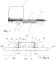
- FIG 1 a side view of an embodiment of a road vehicle 1, in the shown embodiment a tractor for pulling a trailer, according to the invention is schematically shown.
- the road vehicle 1 is provided with a number of battery modules 2, 3, 4, 5, 6, 7 (see also Figure 2 ), and has a chassis 8 comprising a first elongate chassis beam 9 and a second elongate chassis beam 10. Both chassis beams 7, 8 extend along a length of the road vehicle 1.
- the first and second elongate chassis beam 9, 10 each comprise an upper surface 9A, 10A and a lower surface 9B, 10B, an inner surface 9C, 10C and an outer surface 9D, 10D.
- the inner surfaces 9C, 10C of the first and second chassis beams 9, 10 face each other while the outer surfaces 9D, 10D of the first and second chassis beams 9, 10 face away from each other.
- the chassis 8 further comprises cross beams that connect the first elongate chassis beam 9 and the second elongate chassis beam 10, however these are not shown in the Figures for clarity purposes.
- the road vehicle 1 further comprises a battery module mounting system 11 for mounting the battery modules 2, 3, 4, 5, 6, 7 to the chassis 8, the battery mounting system 11 comprising at least two battery mounting units embodiments of which are depicted and described in a more detailed manner with reference to Figures 2 to 6 .
- each of the battery mounting units comprises a U-shaped top plate 12, 13, 14 having a base portion 12A, 13A, 14A and two arm portions 12B, 12C; 13B, 13C; 14B, 14C.
- the arm portions 12B, 12C; 13B, 13C; 14B, 14C extend downwards from the base portion 12A, 13A, 14A.
- Each of the arm portions 12B, 12C; 13B, 13C; 14B, 14C is connected to a respective one of the outer surfaces 9D, 10D of the first and second chassis beams 9, 10, for example by means of bolts and nuts.
- the base portion 12A, 13A, 14A thus horizontally extends over the upper surfaces 9A, 10A of the first and second elongate chassis beams 9, 10 providing increased stiffness to the chassis.
- Each battery mounting unit further comprises a battery module carrier beam 15, 16, 17, preferably formed by a hollow, substantially rectangular metal beam, that extends below and transverse to the first or second elongate chassis beam 9, 10.
- the battery module carrier beam 15, 16, 17 has free ends 15A, 15B; 16A, 16B; 17A, 17B positioned outwardly at a distance from the outer surface 9D, 10D of the first and second elongate chassis beams 9, 10.
- attachment brackets 18 the battery module carrier beam 15, 16, 17 is attached to the arm portions 12B, 12C; 13B, 13C; 14B, 14C of the respective U-shaped top plate 12, 13, 14.
- the distance or spacing between the battery module carrier beams 15, 16, 17 of two adjacent battery mounting units is such that a battery module 2, 3, 4, 5, 6, 7 can be received and positioned between two adjacent battery mounting units.
- the battery modules 2, 3, 4, 5, 6, 7 are supported on the battery module carrier beams 15, 16, 17 by means of a number of elastic connectors 23.
- the base portion 12A, 13A, 14A of the U-shaped top plate 12, 13, 14 is narrower in a middle section than at end sections adjacent the arm portions 12B, 12C; 13B, 13C; 14B, 14C for providing sufficient longitudinal stiffness to the chassis while the weight of the U-shaped top plate can be kept relatively low.
- the base portion 12A of the U-shaped top plate 12 is provided with cut-aways 19 providing the base portion 12A with diagonal cross elements 20, 21 (the diagonal extension of the elements being indicated by dotted lines) leading to a further weight reduction without detrimentally influencing the longitudinal stiffness.
- the thickness of the battery module carrier beam 15 is smaller in a middle section 15M thereof than at the free ends 15A, 15B thereof, and the height of the battery module carrier beam 15 is larger in this middle section 15M than at the free ends 15A, 15B. This provides a stiff area in vertical direction of the battery module carrier beam 15 while on the other hand chassis torsion can be handled relatively well.
Landscapes
- Engineering & Computer Science (AREA)
- Chemical & Material Sciences (AREA)
- Combustion & Propulsion (AREA)
- Transportation (AREA)
- Mechanical Engineering (AREA)
- Battery Mounting, Suspending (AREA)
- Arrangement Or Mounting Of Propulsion Units For Vehicles (AREA)
Abstract
Description
- The invention relates to a road vehicle according to the preamble of
claim 1. - Such a road vehicle is e.g. known from
EP4088959A1 . This known road vehicle comprises a power supply system for supplying power to a power system of the road vehicle and comprises a battery mounting system comprising a bracket assembly that is provided above and below the chassis beams of the frame of the road vehicle. First cases are provided on the bracket assembly and first power battery modules are suspended inside the first cases. The bracket assembly comprises an upper bracket body and two lower bracket bodies, wherein each of the lower bracket bodies is connected to the lower end of each of the first cases in one-to-one correspondence. The upper bracket body and the lower bracket bodies are parallel to each other and connected by angular beams. The lower bracket bodies are connected by horizontal beams extending transverse to the chassis beams. The bracket assembly is connected to the chassis beams through bolts. The connection position between the bracket assembly and the chassis beams can be located at the front, middle or rear of the frame. The upper bracket body is connected to the frame by bolts, and in order to further increase the bonding force between the bracket and the frame, a reinforced rib plate is used for furthering reinforcing the upper bracket body and the frame. - The present invention in particular relates to heavy load road vehicles such as trucks. Trucks in general are used to transport heavy loads over long distances. Particularly in case of heavy duty long haulage applications a plurality of battery modules is equipped on the trucks, each module weighing about 850 kg or more. Typically these battery modules are fragile and suffer from vibrations, shocks, and deformation.
- A truck and in particular a tractor to pull a semi-trailer is conventionally built upon a chassis formed by two elongate chassis beams connected by cross beams, i.e. a so called ladder frame. Such a ladder frame has a slender shape resulting in an elasticity that allows attached components to swing and vibrate, when the truck is in motion. These vibrations may be damaging to the battery packs that are attached to the frame. The slender shape of the ladder frame also allows longitudinal twisting of the truck, due to the forces and vibrations when the truck is in motion. Such a twisting may also be detrimental to the battery packs that are attached to the frame.
- Although
EP4088959A1 provides some reinforcement between battery module mounting system and chassis it is however desired, in view of the increased number of battery modules used, and thus inter alia the increased weight of the battery modules, to further increase the stiffness of the combination of chassis and battery module mounting system without adding to much weight to either the chassis or the battery module mounting system in view of energy consumption. In particular, due to the desire to use an increased number of battery modules, thus adding to the weight of the components connected to the chassis and increasing global twisting of the chassis, which could lead to damage of the battery nodules, it is an object of the invention to provide an alternative road vehicle in which the stiffness of the chassis and the battery module mounting system is increased while keeping the total weight of these components relatively low. - In accordance with the invention this object is obtained by a road vehicle according to
claim 1. By means of the U-shaped top plate the chassis is strongly reinforced, leading to a structure that is very stiff, strongly reducing twisting of the chassis beams which could damage the battery modules. Due to the battery module carrier beams which are attached to the arm portions of a respective U-shaped top plate via the attachment brackets the construction of the battery module mounting system can be realized in a rather lightweight manner resulting in weight and costs reductions. - In an embodiment of a road vehicle according to the invention the base portion of the U-shaped top plate is narrower in a middle section than at end sections adjacent the arm portions. In this manner sufficient longitudinal stiffness is provided to the chassis while the weight of the U-shaped top plate can be kept relatively low. Preferably, the base portion of the U-shaped top plate is provided with cut-aways for providing the base portion of the U-shaped top plate with diagonal cross elements, providing a further weight reduction without detrimentally influencing the longitudinal stiffness.
- In a further embodiment of a road vehicle according to the invention the thickness of the battery module carrier beam is smaller in a middle section thereof than at the free ends thereof. This provides a stiff area in vertical direction of the battery module carrier beam while on the other hand chassis torsion can be handled relatively well. These latter effects are more pronounced when the height of the battery module carrier beam is larger in a middle section thereof than at the free ends thereof.
- In a still further embodiment of a road vehicle according the invention the battery module is supported on the battery module carrier beams by means of elastic connectors. In this manner vibrations and twisting of the chassis are passed on to the battery modules in a lesser extent, reducing the risk of damaging the battery modules.
- The invention will be further explained with reference to the Figures, in which non-limiting exemplary embodiments of a road vehicle according to the invention are schematically shown.
-
-
Figure 1 schematically shows a side view of an embodiment of a road vehicle according to the invention; -
Figure 2 schematically shows a perspective view of part of a chassis and the battery module mounting system of an embodiment of a road vehicle according to the invention; -
Figure 3 schematically shows a perspective view of a part of the embodiment ofFigure 2 seen from a more forward position; -
Figure 4 schematically shows a top view ofFigure 2 ; -
Figure 5 schematically shows a perspective view of an embodiment of a battery mounting unit without battery modules; and -
Figure 6 schematically shows a front view of the embodiment ofFigure 2 . - In
Figure 1 a side view of an embodiment of aroad vehicle 1, in the shown embodiment a tractor for pulling a trailer, according to the invention is schematically shown. Theroad vehicle 1 is provided with a number ofbattery modules Figure 2 ), and has achassis 8 comprising a firstelongate chassis beam 9 and a secondelongate chassis beam 10. Bothchassis beams road vehicle 1. - As indicated in
Figure 6 the first and secondelongate chassis beam upper surface lower surface inner surface outer surface inner surfaces second chassis beams outer surfaces second chassis beams chassis 8 further comprises cross beams that connect the firstelongate chassis beam 9 and the secondelongate chassis beam 10, however these are not shown in the Figures for clarity purposes. - The
road vehicle 1 further comprises a batterymodule mounting system 11 for mounting thebattery modules chassis 8, thebattery mounting system 11 comprising at least two battery mounting units embodiments of which are depicted and described in a more detailed manner with reference toFigures 2 to 6 . - As shown in the drawings each of the battery mounting units comprises a
U-shaped top plate base portion arm portions arm portions base portion arm portions outer surfaces second chassis beams base portion upper surfaces elongate chassis beams - Each battery mounting unit further comprises a battery
module carrier beam elongate chassis beam module carrier beam free ends outer surface elongate chassis beams attachment brackets 18 the batterymodule carrier beam arm portions top plate - The distance or spacing between the battery
module carrier beams battery module battery modules module carrier beams elastic connectors 23. - As for example can be seen in
Figures 3 and5 thebase portion top plate arm portions Figure 5 , thebase portion 12A of the U-shapedtop plate 12 is provided with cut-aways 19 providing thebase portion 12A withdiagonal cross elements 20, 21 (the diagonal extension of the elements being indicated by dotted lines) leading to a further weight reduction without detrimentally influencing the longitudinal stiffness. - As indicated in the embodiment of
Figures 3 and6 the thickness of the batterymodule carrier beam 15 is smaller in amiddle section 15M thereof than at thefree ends module carrier beam 15 is larger in thismiddle section 15M than at thefree ends module carrier beam 15 while on the other hand chassis torsion can be handled relatively well.
Claims (6)
- A road vehicle (1) provided with:- a battery module (2, 3, 4, 5, 6, 7);- a chassis (8) comprising a first elongate chassis beam (9) and a second elongate chassis beam (10), both extending along a length of the road vehicle (1), each first and second elongate chassis beam (9, 10) comprising an upper surface (9A, 10A) and a lower surface(9B, 10B), an inner surface (9C, 10C) and an outer surface (9D, 10D), the inner surfaces (9C, 10C) of the first and second chassis beams (9, 10) facing each other, the outer surfaces (9D, 10D) of the first and second elongate chassis beams (9, 10) facing away from each other;a battery module mounting system (11) for mounting the battery module (2, 3, 4, 5, 6, 7) to the chassis (8);characterized in that the battery mounting system (11) comprises at least two battery mounting units each comprising:- a U-shaped top plate (12, 13, 14) having a base portion (12A, 13A, 14A) and arm portions (12B, 12C; 13B, 13C; 14B, 14C), each of the arm portions (12B, 12C; 13B, 13C; 14B, 14C) being connected to a respective one of the outer surfaces (9D, 10D) of the first and second chassis beams (9, 10), the base portion (12A, 13A, 14A) horizontally extending over the upper surfaces (9A, 10A) of the first and second elongate chassis beams (9, 10);- a battery module carrier beam (15, 16, 17) extending below and transverse to the first or second elongate chassis beam (9, 10), the battery module carrier beam (15, 16, 17) having free ends (15A, 15B; 16A, 16B; 17A, 17B) positioned outwardly at a distance from the outer surface (9D, 10D) of the first and second elongate chassis beams (9, 10); and- attachment brackets (18) attaching the battery module carrier beam (15, 16, 17) to the arm portions (12B, 12C; 13B, 13C; 14B, 14C) of the respective U-shaped top plate (12, 13, 14),wherein the battery module carrier beams (15, 16, 17) of two adjacent battery mounting units are spaced from each other for receiving a respective battery module (2, 3, 4, 5, 6, 7).
- The road vehicle (1) according to claim 1, wherein the base portion (12A, 13A, 14A) of the U-shaped top plate (12, 13, 14) is narrower in a middle section than at end sections adjacent the arm portions (12B, 12C; 13B, 13C; 14B, 14C).
- The road vehicle (1) according to claim 1 or 2, wherein the base portion (12A, 13A, 14A) of the U-shaped top plate (12, 13, 14) is provided with cut-aways (19) for providing the base portion (12A, 13A, 14A) of the U-shaped top plate (12, 13, 14) with diagonal cross elements (20, 21).
- The road vehicle (1) according to any one of the preceding claims, wherein the thickness of the battery module carrier beam (15, 16, 17) is smaller in a middle section thereof than at the free ends (15A, 15B; 16A, 16B; 17A, 17B) thereof.
- The road vehicle (1) according to any one of the preceding claims, wherein the height of the battery module carrier beam (15, 16, 17) is larger in a middle section thereof than at the free ends (15A, 15B; 16A, 16B; 17A, 17B) thereof.
- The road vehicle (1) according to any one of the preceding claims, wherein the battery module (2, 3, 4, 5, 6, 7) is supported on the battery module carrier beams (15, 16, 17) by means of elastic connectors (22).
Applications Claiming Priority (1)
| Application Number | Priority Date | Filing Date | Title |
|---|---|---|---|
| NL2034457A NL2034457B1 (en) | 2023-03-29 | 2023-03-29 | A road vehicle |
Publications (3)
| Publication Number | Publication Date |
|---|---|
| EP4438365A1 true EP4438365A1 (en) | 2024-10-02 |
| EP4438365C0 EP4438365C0 (en) | 2025-08-20 |
| EP4438365B1 EP4438365B1 (en) | 2025-08-20 |
Family
ID=86604768
Family Applications (1)
| Application Number | Title | Priority Date | Filing Date |
|---|---|---|---|
| EP24167313.6A Active EP4438365B1 (en) | 2023-03-29 | 2024-03-28 | A road vehicle |
Country Status (2)
| Country | Link |
|---|---|
| EP (1) | EP4438365B1 (en) |
| NL (1) | NL2034457B1 (en) |
Cited By (3)
| Publication number | Priority date | Publication date | Assignee | Title |
|---|---|---|---|---|
| CN119190195A (en) * | 2024-11-26 | 2024-12-27 | 江苏速豹动力科技有限公司 | An electric heavy truck and its frame assembly |
| US12502942B1 (en) | 2021-06-29 | 2025-12-23 | Oshkosh Corporation | Vehicle with reconfigurable energy storage |
| US12533937B2 (en) | 2022-06-28 | 2026-01-27 | Oshkosh Corporation | Steps and mounting for underslung battery pack |
Citations (4)
| Publication number | Priority date | Publication date | Assignee | Title |
|---|---|---|---|---|
| US10493837B1 (en) * | 2018-10-11 | 2019-12-03 | Paccar Inc | Chassis mounted assemblies for electric or hybrid vehicles |
| US20220169126A1 (en) * | 2020-11-30 | 2022-06-02 | Nikola Corporation | Electric vehicle battery frame assembly |
| EP4088959A1 (en) | 2020-03-24 | 2022-11-16 | Hoitunginnotek (Shenzhen) Co., Ltd. | Power supply system |
| US20230001986A1 (en) * | 2021-06-30 | 2023-01-05 | Volvo Truck Corporation | Chassis assembly for a vehicle |
-
2023
- 2023-03-29 NL NL2034457A patent/NL2034457B1/en active
-
2024
- 2024-03-28 EP EP24167313.6A patent/EP4438365B1/en active Active
Patent Citations (4)
| Publication number | Priority date | Publication date | Assignee | Title |
|---|---|---|---|---|
| US10493837B1 (en) * | 2018-10-11 | 2019-12-03 | Paccar Inc | Chassis mounted assemblies for electric or hybrid vehicles |
| EP4088959A1 (en) | 2020-03-24 | 2022-11-16 | Hoitunginnotek (Shenzhen) Co., Ltd. | Power supply system |
| US20220169126A1 (en) * | 2020-11-30 | 2022-06-02 | Nikola Corporation | Electric vehicle battery frame assembly |
| US20230001986A1 (en) * | 2021-06-30 | 2023-01-05 | Volvo Truck Corporation | Chassis assembly for a vehicle |
Cited By (3)
| Publication number | Priority date | Publication date | Assignee | Title |
|---|---|---|---|---|
| US12502942B1 (en) | 2021-06-29 | 2025-12-23 | Oshkosh Corporation | Vehicle with reconfigurable energy storage |
| US12533937B2 (en) | 2022-06-28 | 2026-01-27 | Oshkosh Corporation | Steps and mounting for underslung battery pack |
| CN119190195A (en) * | 2024-11-26 | 2024-12-27 | 江苏速豹动力科技有限公司 | An electric heavy truck and its frame assembly |
Also Published As
| Publication number | Publication date |
|---|---|
| EP4438365C0 (en) | 2025-08-20 |
| EP4438365B1 (en) | 2025-08-20 |
| NL2034457B1 (en) | 2024-10-08 |
Similar Documents
| Publication | Publication Date | Title |
|---|---|---|
| EP4438365B1 (en) | A road vehicle | |
| US7264304B2 (en) | Vehicle body | |
| US20040100127A1 (en) | Vehicle front body structure | |
| NL2034455B1 (en) | A road vehicle | |
| KR20050085946A (en) | Forward frame part for a utility vehicle | |
| EP3964426B1 (en) | Electric truck frame | |
| US20240359747A1 (en) | Side sill assembly for a vehicle | |
| CN115989172A (en) | Energy storage for electrically driven cars - Underbody components | |
| CN112208638A (en) | Frame and electric vehicle | |
| EP4349626B1 (en) | A vehicle provided with an electric motor | |
| CN118478943A (en) | Frame assembly and vehicle | |
| CN220391349U (en) | Suspension mounting structure and vehicle | |
| CN112758190A (en) | Automobile engine cabin longitudinal beam assembly | |
| US11148490B2 (en) | Towing hook mounting structure | |
| EP4257454B1 (en) | Road vehicle with battery mounting arrangement | |
| NL2034540B1 (en) | A road vehicle | |
| CN210126424U (en) | Aluminum alloy installation device of automobile battery pack and automobile | |
| CN210126555U (en) | Aluminum alloy front auxiliary frame | |
| CN214324832U (en) | A thrust rod installation beam assembly and vehicle | |
| KR20210063839A (en) | Modular chassis frame for vehicles | |
| CN219998474U (en) | Unmanned cab antenna support of off-highway dumper | |
| CN121671241A (en) | Leaf spring lug support mounting structure, lower automobile body and vehicle | |
| CN224013706U (en) | Vehicle body structure and vehicle | |
| US20260131610A1 (en) | Suspension member assembly | |
| CN105059393A (en) | Lightweight chassis structure |
Legal Events
| Date | Code | Title | Description |
|---|---|---|---|
| PUAI | Public reference made under article 153(3) epc to a published international application that has entered the european phase |
Free format text: ORIGINAL CODE: 0009012 |
|
| STAA | Information on the status of an ep patent application or granted ep patent |
Free format text: STATUS: REQUEST FOR EXAMINATION WAS MADE |
|
| 17P | Request for examination filed |
Effective date: 20240328 |
|
| AK | Designated contracting states |
Kind code of ref document: A1 Designated state(s): AL AT BE BG CH CY CZ DE DK EE ES FI FR GB GR HR HU IE IS IT LI LT LU LV MC ME MK MT NL NO PL PT RO RS SE SI SK SM TR |
|
| GRAP | Despatch of communication of intention to grant a patent |
Free format text: ORIGINAL CODE: EPIDOSNIGR1 |
|
| STAA | Information on the status of an ep patent application or granted ep patent |
Free format text: STATUS: GRANT OF PATENT IS INTENDED |
|
| RIC1 | Information provided on ipc code assigned before grant |
Ipc: B62D 21/02 20060101ALN20250228BHEP Ipc: B60K 1/04 20190101AFI20250228BHEP |
|
| INTG | Intention to grant announced |
Effective date: 20250313 |
|
| GRAS | Grant fee paid |
Free format text: ORIGINAL CODE: EPIDOSNIGR3 |
|
| GRAA | (expected) grant |
Free format text: ORIGINAL CODE: 0009210 |
|
| STAA | Information on the status of an ep patent application or granted ep patent |
Free format text: STATUS: THE PATENT HAS BEEN GRANTED |
|
| AK | Designated contracting states |
Kind code of ref document: B1 Designated state(s): AL AT BE BG CH CY CZ DE DK EE ES FI FR GB GR HR HU IE IS IT LI LT LU LV MC ME MK MT NL NO PL PT RO RS SE SI SK SM TR |
|
| REG | Reference to a national code |
Ref country code: GB Ref legal event code: FG4D |
|
| REG | Reference to a national code |
Ref country code: CH Ref legal event code: EP |
|
| REG | Reference to a national code |
Ref country code: IE Ref legal event code: FG4D |
|
| REG | Reference to a national code |
Ref country code: DE Ref legal event code: R096 Ref document number: 602024000487 Country of ref document: DE |
|
| U01 | Request for unitary effect filed |
Effective date: 20250908 |
|
| U07 | Unitary effect registered |
Designated state(s): AT BE BG DE DK EE FI FR IT LT LU LV MT NL PT RO SE SI Effective date: 20250915 |
|
| PG25 | Lapsed in a contracting state [announced via postgrant information from national office to epo] |
Ref country code: IS Free format text: LAPSE BECAUSE OF FAILURE TO SUBMIT A TRANSLATION OF THE DESCRIPTION OR TO PAY THE FEE WITHIN THE PRESCRIBED TIME-LIMIT Effective date: 20251220 |
|
| PG25 | Lapsed in a contracting state [announced via postgrant information from national office to epo] |
Ref country code: NO Free format text: LAPSE BECAUSE OF FAILURE TO SUBMIT A TRANSLATION OF THE DESCRIPTION OR TO PAY THE FEE WITHIN THE PRESCRIBED TIME-LIMIT Effective date: 20251120 |
|
| PG25 | Lapsed in a contracting state [announced via postgrant information from national office to epo] |
Ref country code: HR Free format text: LAPSE BECAUSE OF FAILURE TO SUBMIT A TRANSLATION OF THE DESCRIPTION OR TO PAY THE FEE WITHIN THE PRESCRIBED TIME-LIMIT Effective date: 20250820 |
|
| PG25 | Lapsed in a contracting state [announced via postgrant information from national office to epo] |
Ref country code: GR Free format text: LAPSE BECAUSE OF FAILURE TO SUBMIT A TRANSLATION OF THE DESCRIPTION OR TO PAY THE FEE WITHIN THE PRESCRIBED TIME-LIMIT Effective date: 20251121 |
|
| PG25 | Lapsed in a contracting state [announced via postgrant information from national office to epo] |
Ref country code: PL Free format text: LAPSE BECAUSE OF FAILURE TO SUBMIT A TRANSLATION OF THE DESCRIPTION OR TO PAY THE FEE WITHIN THE PRESCRIBED TIME-LIMIT Effective date: 20250820 |
|
| PG25 | Lapsed in a contracting state [announced via postgrant information from national office to epo] |
Ref country code: RS Free format text: LAPSE BECAUSE OF FAILURE TO SUBMIT A TRANSLATION OF THE DESCRIPTION OR TO PAY THE FEE WITHIN THE PRESCRIBED TIME-LIMIT Effective date: 20251120 |
|
| PG25 | Lapsed in a contracting state [announced via postgrant information from national office to epo] |
Ref country code: ES Free format text: LAPSE BECAUSE OF FAILURE TO SUBMIT A TRANSLATION OF THE DESCRIPTION OR TO PAY THE FEE WITHIN THE PRESCRIBED TIME-LIMIT Effective date: 20250820 |
|
| PG25 | Lapsed in a contracting state [announced via postgrant information from national office to epo] |
Ref country code: SM Free format text: LAPSE BECAUSE OF FAILURE TO SUBMIT A TRANSLATION OF THE DESCRIPTION OR TO PAY THE FEE WITHIN THE PRESCRIBED TIME-LIMIT Effective date: 20250820 |
|
| PG25 | Lapsed in a contracting state [announced via postgrant information from national office to epo] |
Ref country code: CZ Free format text: LAPSE BECAUSE OF FAILURE TO SUBMIT A TRANSLATION OF THE DESCRIPTION OR TO PAY THE FEE WITHIN THE PRESCRIBED TIME-LIMIT Effective date: 20250820 |
|
| PG25 | Lapsed in a contracting state [announced via postgrant information from national office to epo] |
Ref country code: SK Free format text: LAPSE BECAUSE OF FAILURE TO SUBMIT A TRANSLATION OF THE DESCRIPTION OR TO PAY THE FEE WITHIN THE PRESCRIBED TIME-LIMIT Effective date: 20250820 |
|
| U20 | Renewal fee for the european patent with unitary effect paid |
Year of fee payment: 3 Effective date: 20260326 |
|
| PLBE | No opposition filed within time limit |
Free format text: ORIGINAL CODE: 0009261 |
|
| STAA | Information on the status of an ep patent application or granted ep patent |
Free format text: STATUS: NO OPPOSITION FILED WITHIN TIME LIMIT |
|
| REG | Reference to a national code |
Ref country code: CH Ref legal event code: L10 Free format text: ST27 STATUS EVENT CODE: U-0-0-L10-L00 (AS PROVIDED BY THE NATIONAL OFFICE) Effective date: 20260701 |
|
| 26N | No opposition filed |
Effective date: 20260521 |