EP4438335A1 - Tire - Google Patents
Tire Download PDFInfo
- Publication number
- EP4438335A1 EP4438335A1 EP24157856.6A EP24157856A EP4438335A1 EP 4438335 A1 EP4438335 A1 EP 4438335A1 EP 24157856 A EP24157856 A EP 24157856A EP 4438335 A1 EP4438335 A1 EP 4438335A1
- Authority
- EP
- European Patent Office
- Prior art keywords
- tire
- cap layer
- tread
- groove
- wear
- Prior art date
- Legal status (The legal status is an assumption and is not a legal conclusion. Google has not performed a legal analysis and makes no representation as to the accuracy of the status listed.)
- Granted
Links
Images


Classifications
-
- B—PERFORMING OPERATIONS; TRANSPORTING
- B60—VEHICLES IN GENERAL
- B60C—VEHICLE TYRES; TYRE INFLATION; TYRE CHANGING; CONNECTING VALVES TO INFLATABLE ELASTIC BODIES IN GENERAL; DEVICES OR ARRANGEMENTS RELATED TO TYRES
- B60C11/00—Tyre tread bands; Tread patterns; Anti-skid inserts
- B60C11/0041—Tyre tread bands; Tread patterns; Anti-skid inserts comprising different tread rubber layers
- B60C11/005—Tyre tread bands; Tread patterns; Anti-skid inserts comprising different tread rubber layers with cap and base layers
-
- B—PERFORMING OPERATIONS; TRANSPORTING
- B60—VEHICLES IN GENERAL
- B60C—VEHICLE TYRES; TYRE INFLATION; TYRE CHANGING; CONNECTING VALVES TO INFLATABLE ELASTIC BODIES IN GENERAL; DEVICES OR ARRANGEMENTS RELATED TO TYRES
- B60C11/00—Tyre tread bands; Tread patterns; Anti-skid inserts
- B60C11/03—Tread patterns
- B60C11/12—Tread patterns characterised by the use of narrow slits or incisions, e.g. sipes
- B60C11/1272—Width of the sipe
- B60C11/1281—Width of the sipe different within the same sipe, i.e. enlarged width portion at sipe bottom or along its length
-
- B—PERFORMING OPERATIONS; TRANSPORTING
- B60—VEHICLES IN GENERAL
- B60C—VEHICLE TYRES; TYRE INFLATION; TYRE CHANGING; CONNECTING VALVES TO INFLATABLE ELASTIC BODIES IN GENERAL; DEVICES OR ARRANGEMENTS RELATED TO TYRES
- B60C11/00—Tyre tread bands; Tread patterns; Anti-skid inserts
- B60C11/0008—Tyre tread bands; Tread patterns; Anti-skid inserts characterised by the tread rubber
- B60C2011/0016—Physical properties or dimensions
- B60C2011/0025—Modulus or tan delta
-
- B—PERFORMING OPERATIONS; TRANSPORTING
- B60—VEHICLES IN GENERAL
- B60C—VEHICLE TYRES; TYRE INFLATION; TYRE CHANGING; CONNECTING VALVES TO INFLATABLE ELASTIC BODIES IN GENERAL; DEVICES OR ARRANGEMENTS RELATED TO TYRES
- B60C11/00—Tyre tread bands; Tread patterns; Anti-skid inserts
- B60C11/03—Tread patterns
- B60C2011/0337—Tread patterns characterised by particular design features of the pattern
- B60C2011/0339—Grooves
- B60C2011/0341—Circumferential grooves
- B60C2011/0348—Narrow grooves, i.e. having a width of less than 4 mm
-
- B—PERFORMING OPERATIONS; TRANSPORTING
- B60—VEHICLES IN GENERAL
- B60C—VEHICLE TYRES; TYRE INFLATION; TYRE CHANGING; CONNECTING VALVES TO INFLATABLE ELASTIC BODIES IN GENERAL; DEVICES OR ARRANGEMENTS RELATED TO TYRES
- B60C2200/00—Tyres specially adapted for particular applications
- B60C2200/06—Tyres specially adapted for particular applications for heavy duty vehicles
Definitions
- the present invention relates to a tire.
- the rolling resistance performance and the wear resistance of a tire may decrease due to deformation of land portions during running.
- a tire including a tread having a circumferential narrow groove in order to increase the tread stiffness has been known.
- the circumferential narrow groove has a narrow groove width with which sidewalls thereof come into contact with each other when the tire comes into contact with the ground. Therefore, in the tire having the circumferential narrow groove, land portions can support each other when the tire comes into contact with the ground. Accordingly, the tread stiffness is improved, and the rolling resistance performance and the wear resistance of the tire are improved (see, for example, Japanese Laid-Open Patent Publication No. 2018-202956 ).
- wet performance In the technology described in Japanese Laid-Open Patent Publication No. 2018-202956 , the tread stiffness increases and the groove volume decreases in the late stage of wear, so that there is room for improvement in terms of grip performance on a wet road surface (hereinafter simply referred to as "wet performance").
- the present invention has been made in view of the above circumstances, and an object of the present invention is to provide a tire that can suppress a decrease in grip performance and wet performance in a late stage of wear while improving rolling resistance performance and wear resistance.
- a tire according to an aspect of the present invention is directed to a tire including a tread.
- the tread has a layered structure including a base layer located on an innermost side in a tire radial direction, a first cap layer located on an outermost side in the tire radial direction, and a second cap layer located between the base layer and the first cap layer in the tire radial direction.
- the tread has a tread pattern having a pair of shoulder circumferential grooves, and at least one circumferential narrow groove located inward of each of the shoulder circumferential grooves in a tire width direction.
- the circumferential narrow groove has a narrow portion located on an outer side in the tire radial direction, and a wide portion located on an inner side in the tire radial direction and having a larger groove width than the narrow portion.
- the narrow portion has a groove width with which sidewalls of the narrow portion come into contact with each other when the tire comes into contact with a road surface.
- a complex elastic modulus of the second cap layer is lower than a complex elastic modulus of the first cap layer.
- a maximum groove width of the wide portion is located at a depth of 70 to 90% when a depth from an opening position of the circumferential narrow groove to a bottom portion of the wide portion is defined as 100%.
- the wide portion is configured to gradually widen to a position of the maximum groove width from a position of connection with the narrow portion toward the bottom portion.
- the maximum groove width is located on the bottom portion side with respect to a middle position of a depth from the position of connection to the bottom portion.
- the wide portion is placed in the second cap layer.
- the maximum groove width of the wide portion is three to seven times the groove width of the narrow portion.
- a loss tangent of the second cap layer is higher than a loss tangent of the first cap layer.
- the tread has a shoulder land portion located on an outermost side in the tire width direction demarcated by the shoulder circumferential groove.
- a difference between a thickness of the first cap layer at a center in the tire width direction of the shoulder land portion and a thickness of the first cap layer at an equator plane of the tread is within 2.0 mm.
- the complex elastic modulus of the second cap layer is higher than a complex elastic modulus of the base layer.
- a bottom portion of the shoulder circumferential groove and a bottom portion of the circumferential narrow groove are placed in the second cap layer, and a thickness of the base layer is smaller than a thickness of the second cap layer at the bottom portion of the shoulder circumferential groove and the bottom portion of the circumferential narrow groove.
- the tire is a heavy duty tire.
- a tire that can suppress a decrease in grip performance and wet performance in a late stage of wear while improving rolling resistance performance and wear resistance, is obtained.
- a state where a tire is fitted on a standardized rim, the internal pressure of the tire is adjusted to a standardized internal pressure, and no load is applied to the tire is referred to as standardized state.
- the description is based on the tire in a state where no wear due to running has occurred.
- the dimensions and angles of each component of the tire are measured in the standardized state.
- the dimensions and angles of each component in a meridian cross-section of the tire, which cannot be measured in a state where the tire is fitted on the standardized rim, are measured in a cut plane of the tire obtained by cutting the tire along a plane including a rotation axis.
- the tire is set such that the distance between right and left beads is equal to the distance between the beads in the tire that is fitted on the standardized rim.
- the configuration of the tire that cannot be confirmed in a state where the tire is fitted on the standardized rim is confirmed in the above-described cut plane.
- the standardized rim means a rim specified in a standard on which the tire is based.
- the "standard rim” in the JATMA standard, the "Design Rim” in the TRA standard, and the “Measuring Rim” in the ETRTO standard are standardized rims.
- the standardized internal pressure means an internal pressure specified in the standard on which the tire is based.
- the "highest air pressure” in the JATMA standard, the "maximum value” recited in the "TIRE LOAD LIMITS AT VARIOUS COLD INFLATION PRESSURES" in the TRA standard, and the “INFLATION PRESSURE” in the ETRTO standard are standardized internal pressures.
- a standardized load means a load specified in the standard on which the tire is based.
- the "maximum load capacity" in the JATMA standard, the “maximum value” recited in the "TIRE LOAD LIMITS AT VARIOUS COLD INFLATION PRESSURES" in the TRA standard, and the “LOAD CAPACITY” in the ETRTO standard are standardized loads.
- a tread portion of the tire is a portion of the tire that includes a tread having a surface that comes into contact with a road surface.
- a bead portion is a portion of the tire that is fitted to a rim.
- a side portion is a portion of the tire that extends between the tread portion and the bead portion.
- the tire includes a tread portion, a pair of bead portions, and a pair of side portions as portions thereof.
- a crosslinked rubber refers to a molded product, of a rubber composition, obtained by pressurizing and heating the rubber composition.
- the rubber composition is an uncrosslinked rubber obtained by mixing a base rubber and chemicals in a kneading machine such as a Banbury mixer.
- the crosslinked rubber is also referred to as vulcanized rubber, and the rubber composition is also referred to as unvulcanized rubber.
- Examples of the base rubber include natural rubber (NR), butadiene rubber (BR), styrene-butadiene rubber (SBR), isoprene rubber (IR), ethylene-propylene rubber (EPDM), chloroprene rubber (CR), acrylonitrile-butadiene rubber (NBR), and isobutylene-isoprene-rubber (IIR).
- Examples of the chemicals include reinforcing agents such as carbon black and silica, plasticizers such as aromatic oil, vulcanization aids such as zinc oxide and stearic acid, antioxidants, processing aids, sulfur, and vulcanization accelerators. Selection of a base rubber and chemicals, the amounts of the selected chemicals, etc., are determined as appropriate according to the specifications of components, such as a tread and a sidewall, for which the rubber composition is used.
- a complex elastic modulus hereinafter simply referred to as "E*”
- a loss tangent hereinafter referred to simply as "tan ⁇ ”
- a test piece (40 mm long ⁇ 4 mm wide ⁇ 1 mm thick) is sampled from the tire.
- the length direction of the test piece is caused to coincide with the circumferential direction of the tire.
- a test piece is sampled from a sheet-shaped crosslinked rubber (hereinafter, also referred to as rubber sheet) obtained by pressurizing and heating a rubber composition, which is used for forming the component to be measured, at a temperature of 170°C for 12 minutes.
- E* is represented as E* at 70°C.
- tan ⁇ is represented as tan ⁇ at 0°C.
- the stiffness of a tread is excessively low, a tire deforms excessively during running, and cannot resist a road surface, resulting in a reduced grip force. Conversely, if the stiffness of the tread is excessively high, the deformation of the tire during running is excessively small, resulting in a slip and a reduced grip force. Therefore, the tire is required to have appropriate tread stiffness in order to provide an optimum grip force.
- FIG. 1 is a cross-sectional view showing a part of a tire 1 according to one embodiment of the present invention.
- the tire 1 is mounted to a vehicle such as a truck and a bus.
- the tire 1 is a heavy duty tire.
- FIG. 1 shows a part of a cross-section of the tire 1 taken along a plane including the rotation axis of the tire 1.
- the tire 1 includes a tread 110, a belt 120, a carcass 130, an inner liner 140, a pair of sidewalls 150, a pair of chafers 160, a pair of beads 170, a pair of cushion layers 180, and a pair of steel reinforcing layers 190.
- An alternate long and short dash line EL shown in FIG. 1 indicates the equator plane of the tire 1.
- An equator PE is the point of intersection of the outer surface of the tread 110 and the equator plane EL.
- the equator PE is specified on the basis of a virtual outer surface of the tread 110 obtained on the assumption that the circumferential groove 300 is not provided thereon.
- the width direction of the tire 1 hereinafter sometimes referred to simply as "tire width direction”
- the radial direction of the tire 1 hereinafter sometimes referred to simply as “tire radial direction” are indicated by double-headed arrows.
- the alternate long and short dash line EL side is the inner side in the tire width direction
- the sidewall 150 side is the outer side in the tire width direction
- the rotation axis side is the inner side in the tire radial direction
- the tread 110 side is the outer side in the tire radial direction.
- the direction perpendicular to the drawing sheet of FIG. 1 is the circumferential direction of the tire 1.
- the tire 1 is fitted onto a rim R.
- the rim R is a standardized rim.
- the interior of the tire 1 is filled with air to adjust the internal pressure of the tire 1.
- the tire 1 fitted on the rim R is also referred to as a tire-rim assembly.
- the tire-rim assembly includes the rim R and the tire 1 fitted on the rim R.
- Each sidewall 150 is connected to an end of the tread 110.
- the sidewall 150 extends inward in the tire radial direction from the end of the tread 110.
- the sidewall 150 is formed from a crosslinked rubber for which cut resistance is taken into consideration.
- Each chafer 160 is located inward of the sidewall 150 in the tire radial direction.
- the chafer 160 comes into contact with the rim R.
- the chafer 160 is formed from a crosslinked rubber for which wear resistance is taken into consideration.
- the bead 170 includes an apex 171 and a core 174.
- the core 174 extends in the circumferential direction.
- the core 174 includes a wound wire made of steel.
- the core 174 has a substantially hexagonal cross-sectional shape.
- the apex 171 is located outward of the core 174 in the tire radial direction.
- the apex 171 includes an inner apex 173 and an outer apex 172.
- the inner apex 173 extends outward in the tire radial direction from the core 174.
- the outer apex 172 is located outward of the inner apex 173 in the tire radial direction.
- the inner apex 173 is formed from a hard crosslinked rubber.
- the outer apex 172 is formed from a crosslinked rubber that is more flexible than the inner apex 173.
- the carcass 130 is located inward of the belt 120, the pair of sidewalls 150, and the pair of chafers 160.
- the carcass 130 extends on and between a first bead 170 and a second bead 170 out of the pair of beads 170.
- the carcass 130 includes at least one carcass ply 131.
- the carcass 130 of the tire 1 is composed of one carcass ply 131.
- the carcass ply 131 is turned up around each core 174 from the inner side toward the outer side in the tire width direction.
- the carcass ply 131 includes a ply body 132 which extends on and between a first core 174 and a second core 174, and a pair of turned-up portions 133 which are connected to the ply body 132 and turned up around the respective cores 174 from the inner side toward the outer side in the tire width direction.
- the carcass ply 131 includes a large number of carcass cords aligned with each other, which are not shown. These carcass cords are covered with a topping rubber. Each carcass cord intersects the equator plane EL.
- the carcass 130 has a radial structure.
- the carcass cords of the tire 1 are steel cords.
- Each cushion layer 180 is located between the belt 120 and the carcass 130 on the end side of the belt 120.
- the cushion layer 180 is formed from a flexible crosslinked rubber. The cushion layer 180 alleviates strain generated at the end of the belt 120.
- Each steel reinforcing layer 190 is located at a bead portion.
- the steel reinforcing layer 190 is turned up around the core 174 from the inner side toward the outer side in the tire width direction along the carcass ply 131.
- the steel reinforcing layer 190 includes a large number of filler cords aligned with each other, which are not shown. These filler cords are covered with a topping rubber. Steel cords are used as the filler cords.
- the inner liner 140 is located inward of the carcass 130.
- the inner liner 140 is joined to the inner surface of the carcass 130 via an insulation (not shown) formed from a crosslinked rubber.
- the inner liner 140 forms an inner surface of the tire 1.
- the inner liner 140 is formed from a crosslinked rubber that has an excellent air blocking property.
- the inner liner 140 maintains the internal pressure of the tire 1.
- FIG. 2 shows a part of the tire 1 shown in FIG. 1 .
- FIG. 2 shows an enlarged cross-sectional view of the vicinity of the tread 110 of the tire 1.
- the tire width direction and the tire radial direction are indicated by double-headed arrows.
- the direction perpendicular to the drawing sheet of FIG. 2 is the circumferential direction of the tire 1.
- the belt 120 includes a plurality of belt plies.
- the belt plies include a first belt ply 121, a second belt 122, a third belt ply 123, and a fourth belt ply 124 (hereinafter sometimes referred to as "each belt ply 120").
- Each belt ply 120 includes a large number of belt cords aligned with each other (not shown).
- the belt cords are cords made of a metal. Specifically, the belt cords are steel cords.
- the density of the belt cords in each belt ply 120 are not less than 15 ends/5 cm and not greater than 30 ends/5 cm.
- the first belt ply 121 is located innermost in the tire radial direction.
- the second belt 122 is located outward of the first belt ply 121 in the tire radial direction.
- the third belt ply 123 is located outward of the second belt 122 in the tire radial direction.
- the fourth belt ply 124 is located outward of the third belt ply 123 in the tire radial direction.
- the fourth belt ply 124 is located outermost in the tire radial direction.
- the respective belt plies 120 are aligned in the tire radial direction. Each belt ply 120 is placed such that both ends thereof are opposed to each other across the equator plane EL. Each belt ply 120 intersects the equator plane EL. The ends of each belt ply 120 are located on both sides of the equator plane EL.
- each end of each belt ply 120 is covered with an edge member 125 formed from a crosslinked rubber.
- the edge member 125 contributes to maintaining the interval between the end of the second belt 122 and the end of the third belt ply 123. Accordingly, the durability of the belt 120 is improved.
- the tread 110 comes into contact with a road surface at the outer surface thereof.
- the tread 110 is formed on the belt 120.
- the tread 110 includes a first cap layer 111, a second cap layer 112, and a base layer 113.
- the first cap layer 111 is located on the outermost side of the tread 110 in the tire radial direction.
- the base layer 113 is located on the innermost side of the tread 110 in the tire radial direction.
- the second cap layer 112 is located between the first cap layer 111 and the base layer 113 of the tread 110 in the tire radial direction.
- the first cap layer 111 is stacked on the second cap layer 112, and the second cap layer 112 is stacked on the base layer 113. That is, the tread 110 of the tire 1 has a layered structure including the first cap layer 111, the second cap layer 112, and the base layer 113.
- Circumferential grooves 300 are formed on the tread 110 so as to continuously extend in the circumferential direction, thereby forming a tread pattern.
- four circumferential grooves 300 are formed on the tread 110.
- the tire 1 has five land portions 200 demarcated by the four circumferential grooves 300.
- the tread 110 has a pair of circumferential narrow grooves 320 and a pair of shoulder circumferential grooves 330 as the circumferential grooves 300.
- the tread 110 has one first land portion 210, a pair of second land portions 220, and a pair of shoulder land portions 230 as the land portions 200.
- the pair of shoulder circumferential grooves 330 are formed on the outermost sides of the tread 110 in the tire width direction.
- the pair of circumferential narrow grooves 320 are formed on the inner side of the tread 110 in the tire width direction with respect to the pair of shoulder circumferential grooves 330.
- the first land portion 210 is located in a region demarcated by the pair of circumferential narrow grooves 320.
- the pair of second land portions 220 are located in regions demarcated by the pair of circumferential narrow grooves 320 and the pair of shoulder circumferential grooves 330, respectively.
- the pair of shoulder land portions 230 are located on the outermost sides in the tire width direction demarcated by the shoulder circumferential grooves 330.
- the first cap layer 111 of the tread 110 is initially worn due to running.
- the second cap layer 112 appears on the outer surface of the tire 1.
- late stage of wear the period when the second cap layer 112 begins to appear due to wear of the tread 110 caused by running.
- early stage of wear the period prior to the late stage of wear.
- Each circumferential narrow groove 320 has a narrow groove width with which sidewalls thereof come into contact with each other when the tire 1 comes into contact with the ground. Accordingly, the rolling resistance performance and the wear resistance of the tire 1 are improved.
- the grip performance of the tire decreases due to an increase in tread stiffness.
- the tread stiffness can be reduced by lowering a complex elastic modulus (E*) of the tread at a temperature of 70°C.
- a complex elastic modulus (E*2) of the second cap layer 112 at a temperature of 70°C is lower than a complex elastic modulus (E* 1) of the first cap layer 111 at a temperature of 70°C.
- the second cap layer 112 which has a lower complex elastic modulus at a temperature of 70°C, appears in the late stage of wear. Therefore, in the tire 1, an increase in tread stiffness in the late stage of wear is suppressed, and grip performance is ensured.
- the E* 1 of the first cap layer 111 is higher than the E*2 of the second cap layer 112. Accordingly, in the tire 1, the tread stiffness of the tire 1 in the early stage of wear is maintained. Therefore, in the tire 1, the rolling resistance performance and the wear resistance in the early stage of wear are ensured.
- the E*1 of the first cap layer 111 is not less than 5.0 MPa and preferably not less than 6.5 MPa.
- the rolling resistance performance and the wear resistance in the early stage of wear are ensured.
- the E*1 is not less than 6.5 MPa, excellent rolling resistance performance and wear resistance are exhibited in the early stage of wear.
- the tread stiffness is excessively high, the grip performance is decreased. Therefore, the E* 1 is not greater than 12.0 MPa and preferably not greater than 10.5 MPa.
- the grip performance in the early stage of wear is ensured.
- excellent grip performance is exhibited in the early stage of wear.
- the E*2 of the second cap layer 112 is lower than the E*1 of the first cap layer 111.
- the E*2 is set as appropriate in consideration of the grip performance, the rolling resistance performance, and the wear resistance in the late stage of wear.
- the E*2 is preferably 75 to 90% of the E*1. Accordingly, rapid changes in grip performance, rolling resistance performance, and wear resistance from the early stage of wear to the late stage of wear are suppressed. Therefore, grip performance, rolling resistance performance, and wear resistance are stably exhibited from the early stage of wear to the late stage of wear.
- the E*2 of the second cap layer 112 is preferably higher than a complex elastic modulus (E*3) of the base layer 113 at a temperature of 70°C.
- the complex elastic modulus (E*3) of the base layer 113 at a temperature of 70°C is preferably lower than the E*2 of the second cap layer 112.
- the E*2 is preferably 110 to 125% of the E*3. Accordingly, grip performance, rolling resistance performance, and wear resistance are stably exhibited from the early stage of wear to the late stage of wear.
- the wet performance of a tire decreases.
- the wet performance improves as a loss tangent (tan ⁇ ) of the tread at a temperature of 0°C increases.
- a loss tangent (tan ⁇ 2) of the second cap layer 112 at a temperature of 0°C is higher than a loss tangent (tan ⁇ 1) of the first cap layer 111 at a temperature of 0°C. Therefore, in the tire 1, the second cap layer 112, which has a higher loss tangent at a temperature of 0°C, appears in the late stage of wear. Accordingly, in the tire 1, a decrease in wet performance in the late stage of wear is suppressed.
- the tan ⁇ 2 of the second cap layer 112 is not less than 0.17 and preferably not less than 0.20.
- the tan ⁇ 2 is not less than 0.17, the wet performance in the late stage of wear is ensured.
- the tan ⁇ 2 is not less than 0.20, a decrease in wet performance is effectively suppressed in the late stage of wear.
- a high tan ⁇ may cause generation of heat during running, which may increase the rolling resistance. Therefore, the tan ⁇ 2 is not greater than 0.30 and preferably not greater than 0.27.
- the rolling resistance performance in the late stage of wear is ensured.
- the tan ⁇ 2 is not greater than 0.27, a decrease in rolling resistance performance is effectively suppressed in the late stage of wear.
- the tan 61 of the first cap layer 111 is lower than the tan ⁇ 2 of the second cap layer 112.
- the tan 61 is set as appropriate in consideration of the wet performance, the rolling resistance performance, etc., in the early stage of wear before the second cap layer 112 appears.
- the tan 61 is preferably 80 to 90% of the tan ⁇ 2. Accordingly, rapid changes in wet performance and rolling resistance performance from the early stage of wear to the late stage of wear are suppressed. Therefore, wet performance and rolling resistance performance are stably exhibited from the early stage of wear to the late stage of wear.
- the first cap layer 111, the second cap layer 112, and the base layer 113 are configured to have an almost uniform thickness, except for each circumferential groove 300 and the vicinity of a bottom portion thereof.
- the ratio of the thickness of the first cap layer 111 to the thickness of the tread 110 is 25 to 45%.
- the ratio of the thickness of the second cap layer 112 to the thickness of the tread 110 is 30 to 50%.
- the ratio of the thickness of the base layer 113 to the thickness of the tread 110 is 5 to 45%.
- the thickness of the tread 110 is 15.0 to 25.0 mm.
- HTW shown in FIG. 2 denotes the width in the tire width direction from the equator PE to the edge on the outermost side in the tire width direction of the outer surface of the shoulder land portion 230.
- SMW denotes the maximum groove width of the shoulder circumferential groove 330.
- the groove width SMW is larger than a groove width NW of the circumferential narrow groove 320 described later.
- the ratio of the groove width SMW to the width HTW exceeds 4.0%. Accordingly, the wet performance of the tire 1 is ensured. In addition, the ratio of the groove width SMW to the width HTW is not greater than 20%. Accordingly, the wear resistance of the tire 1 is ensured.
- each circumferential groove 300 is located in the second cap layer 112. As shown in FIG. 2 , the thickness of the base layer 113 is reduced in the vicinity of the bottom portion of each circumferential groove 300 such that the vicinity of the bottom portion of each circumferential groove 300 is covered with the second cap layer 112.
- each circumferential groove 300 can be set as appropriate in consideration of the thickness and the layered structure of the tread 110.
- the depth of each circumferential groove 300 of the tire 1 is 10 to 21 mm.
- the depth of each circumferential groove 300 is preferably 13 to 18 mm.
- the ground-contact pressure at the outer surface of the tread is higher on the inner side in the tire width direction than on the outer side in the tire width direction. Therefore, during running, the tread may be worn on the inner side in the tire width direction more than on the outer side in the tire width direction (hereinafter sometimes referred to simply as "uneven wear").
- the circumferential narrow grooves 320 are formed on the inner side in the tire width direction. Accordingly, in the tire 1, the above ground-contact pressure is distributed to each land portion 200 of the tread 110, so that uneven wear is suppressed.
- the uniformity when the second cap layer 112 appears on the outer surface of the tread 110 is improved. Accordingly, in the tire 1, stable grip performance and wet performance are ensured from the early stage of wear to the late stage of wear.
- H1 shown in FIG. 2 denotes the thickness of the first cap layer 111 at the equator plane EL.
- the thickness H1 is also the thickness of the first cap layer 111 at the center in the tire width direction of the outer surface of the first land portion 210.
- H2 denotes the thickness of the first cap layer 111 at the center in the tire width direction of the outer surface of the shoulder land portion 230.
- a value obtained by subtracting the thickness H2 from the thickness H1 is -2.0 to +2.0 mm. That is, the tire 1 is configured such that the thickness difference from the thickness H1 is within 2.0 mm. Accordingly, the uniformity when the second cap layer 112 appears on the outer surface of the tread 110 in the late stage of wear is improved. Therefore, uneven wear of the tread 110 is suppressed, and the wear resistance of the tire 1 is improved. As a result, in the tire 1, stable grip performance and wet performance are ensured from the early stage of wear to the late stage of wear.
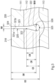
- FIG. 3 is an enlarged cross-sectional view showing the vicinity of the circumferential narrow groove 320 in FIG. 2 .
- the circumferential narrow groove 320 includes a narrow portion 321 on the outer side in the tire radial direction, and a wide portion 322 on the inner side in the tire radial direction.
- the narrow portion 321 and the wide portion 322 are connected by a connection portion 323.
- 324 shown in FIG. 3 denotes the opening of the circumferential narrow groove 320.
- the opening 324 is also the opening of the narrow portion 321.
- 325 shown in FIG. 3 denotes a bottom portion of the circumferential narrow groove 320.
- the bottom portion 325 is also a bottom portion of the wide portion 322.
- 326 shown in FIG. 3 denotes a maximum groove width portion of the wide portion 322.
- the maximum groove width portion 326 is also a maximum groove width portion of the circumferential narrow groove 320.
- OB shown in FIG. 3 denotes the depth of the circumferential narrow groove 320. That is, the depth OB is the depth from the opening 324 to the bottom portion 325 in the tire radial direction.
- OW denotes the depth from the opening 324 to the maximum groove width portion 326 in the tire radial direction.
- CB denotes the depth from the connection portion 323 to the bottom portion 325 in the tire radial direction.
- CW denotes the depth from the connection portion 323 to the maximum groove width portion 326 in the tire radial direction.
- CM denotes the depth from the connection portion 323 to the middle position of the depth CB in the tire radial direction.
- NW denotes the groove width of the narrow portion 321.
- MXW denotes the groove width at the maximum groove width portion 326.
- the narrow portion 321 has the almost uniform groove width NW from the opening 324 to the connection portion 323.
- the groove width NW is set to be a width with which a sidewall 321a and a sidewall 321b of the narrow portion 321 come into contact with each other when the tire 1 comes into contact with a road surface.
- the sidewall 321a is also a sidewall of the first land portion 210.
- the sidewall 321b is also a sidewall of the second land portion 220. That is, the tire 1 is configured such that the first land portion 210 and the second land portion 220 can support each other when the tire 1 comes into contact with a road surface. Accordingly, in the tire 1, the stiffness of the tread 110 in the early stage of wear is improved. Therefore, the rolling resistance performance and the wear resistance of the tire 1 are improved.
- the groove width NW is not less than 1.0 mm and preferably not less than 1.5 mm.
- the groove width NW is not greater than 3.0 mm and preferably not greater than 2.5 mm.
- the groove width NW is not greater than 3.0 mm, the sidewall 321a and the sidewall 321b can come into sufficient contact with each other when the tire 1 comes into contact with a road surface. Therefore, the stiffness of the tread 110 is improved. Accordingly, the rolling resistance performance and the wear resistance of the tire 1 in the early stage of wear are improved.
- the groove width NW is not greater than 2.5 mm, excellent rolling resistance performance and wear resistance are exhibited in the early stage of wear.
- the narrow portion 321 of the tire 1 has the almost uniform groove width NW. Therefore, in the tire 1, the position where the width on the outer side in the tire radial direction with respect to the groove width MXW of the wide portion 322 is equal to the groove width NW is the connection portion 323. In the case where the groove width NW of the narrow portion 321 is not uniform, the position where the width on the outer side in the tire radial direction with respect to the groove width MXW of the wide portion 322 is not greater than 3.0 mm is the connection portion 323.
- the groove width MXW is not less than three times and preferably not less than four times the groove width NW.
- the groove width MXW is not less than three times the groove width NW, an increase in the stiffness of the tread 110 in the late stage of wear is suppressed. Therefore, the grip performance in the late stage of wear is improved. In addition, the drainage performance in the late stage of wear is ensured, and wet performance is improved.
- the groove width MXW is not less than four times the groove width NW, excellent grip performance and wet performance are exhibited in the late stage of wear.
- the groove width MXW is not greater than seven times and preferably not greater than six times the groove width NW.
- the groove width MXW is not greater than seven times the groove width NW, the stiffness of the tread 110 in the early stage of wear is ensured, and the rolling resistance performance and the wear resistance are improved.
- the groove width MXW is not greater than six times the groove width NW, excellent rolling resistance performance and wear resistance are exhibited in the early stage of wear.
- the depth CW is set at the position of 70 to 90% of the depth OB. That is, the tire 1 is configured such that the maximum groove width portion 326 appears on the outer side of the tread 110 in the late stage of wear in which a decrease in grip performance and wet performance becomes significant. Accordingly, the tire 1 can effectively suppress a decrease in grip performance and wet performance in the late stage of wear.
- a decrease in grip performance and wet performance in the late stage of wear progresses gradually. As described above, a decrease in grip performance and wet performance becomes significant when the tread is worn beyond 70% of the groove depth thereof.
- the tire 1 is configured such that the groove width gradually increases from the connection portion 323 toward the maximum groove width portion 326. Furthermore, the depth CW is located deeper than the depth CM. Therefore, in the tire 1, rapid changes in grip performance and wet performance in the late stage of wear are suppressed. As a result, stable grip performance and wet performance are exhibited in the late stage of wear.
- the second cap layer 112 has a lower complex elastic modulus than the first cap layer 111.
- the wide portion 322 is placed in the second cap layer 112. That is, the tire 1 is configured such that the second cap layer 112, which is more flexible than the first cap layer 111, covers the wide portion 322. Accordingly, the stiffness of the tread 110 in the late stage of wear is made appropriate. As a result, the tire 1 exhibits excellent grip performance in the late stage of wear.
- the tire 1 is a heavy duty tire, but the present invention is not limited thereto.
- the present invention can be applied to a tire for a passenger car.
- the tread 110 of the tire 1 has the five land portions 200 demarcated by the four circumferential grooves 300, but the present invention is not limited thereto.
- the tire of the present invention can be configured to have more circumferential narrow grooves 320 than the tire 1.
- the groove width of the narrow portion 321 can be set to vary from 1.5 to 3.0 mm.
- the narrow portion of the tire of the present invention can be configured such that the groove width at the opening thereof is 1.5 mm, the groove width of the connection portion is 3.0 mm, and the groove width gradually increases. Accordingly, stable grip performance and wet performance are exhibited from the early stage of wear to the late stage of wear.
- the above-described technology capable of suppressing a decrease in grip performance and wet performance in a late stage of wear while improving rolling resistance performance and wear resistance can be applied to various tires.
Landscapes
- Engineering & Computer Science (AREA)
- Mechanical Engineering (AREA)
- Tires In General (AREA)
Abstract
Description
- The present invention relates to a tire.
- The rolling resistance performance and the wear resistance of a tire may decrease due to deformation of land portions during running. A tire including a tread having a circumferential narrow groove in order to increase the tread stiffness has been known. The circumferential narrow groove has a narrow groove width with which sidewalls thereof come into contact with each other when the tire comes into contact with the ground. Therefore, in the tire having the circumferential narrow groove, land portions can support each other when the tire comes into contact with the ground. Accordingly, the tread stiffness is improved, and the rolling resistance performance and the wear resistance of the tire are improved (see, for example,
Japanese Laid-Open Patent Publication No. 2018-202956 - In the technology described in
Japanese Laid-Open Patent Publication No. 2018-202956 - The present invention has been made in view of the above circumstances, and an object of the present invention is to provide a tire that can suppress a decrease in grip performance and wet performance in a late stage of wear while improving rolling resistance performance and wear resistance.
- A tire according to an aspect of the present invention is directed to a tire including a tread. The tread has a layered structure including a base layer located on an innermost side in a tire radial direction, a first cap layer located on an outermost side in the tire radial direction, and a second cap layer located between the base layer and the first cap layer in the tire radial direction. The tread has a tread pattern having a pair of shoulder circumferential grooves, and at least one circumferential narrow groove located inward of each of the shoulder circumferential grooves in a tire width direction. The circumferential narrow groove has a narrow portion located on an outer side in the tire radial direction, and a wide portion located on an inner side in the tire radial direction and having a larger groove width than the narrow portion. The narrow portion has a groove width with which sidewalls of the narrow portion come into contact with each other when the tire comes into contact with a road surface. A complex elastic modulus of the second cap layer is lower than a complex elastic modulus of the first cap layer.
- Preferably, in the tire, a maximum groove width of the wide portion is located at a depth of 70 to 90% when a depth from an opening position of the circumferential narrow groove to a bottom portion of the wide portion is defined as 100%.
- Preferably, in the tire, the wide portion is configured to gradually widen to a position of the maximum groove width from a position of connection with the narrow portion toward the bottom portion. The maximum groove width is located on the bottom portion side with respect to a middle position of a depth from the position of connection to the bottom portion.
- Preferably, in the tire, the wide portion is placed in the second cap layer.
- Preferably, in the tire, the maximum groove width of the wide portion is three to seven times the groove width of the narrow portion.
- Preferably, in the tire, a loss tangent of the second cap layer is higher than a loss tangent of the first cap layer.
- The tread has a shoulder land portion located on an outermost side in the tire width direction demarcated by the shoulder circumferential groove. Preferably, a difference between a thickness of the first cap layer at a center in the tire width direction of the shoulder land portion and a thickness of the first cap layer at an equator plane of the tread is within 2.0 mm.
- Preferably, in the tire, the complex elastic modulus of the second cap layer is higher than a complex elastic modulus of the base layer.
- Preferably, in the tire, a bottom portion of the shoulder circumferential groove and a bottom portion of the circumferential narrow groove are placed in the second cap layer, and a thickness of the base layer is smaller than a thickness of the second cap layer at the bottom portion of the shoulder circumferential groove and the bottom portion of the circumferential narrow groove.
- Preferably, the tire is a heavy duty tire.
- According to the present invention, a tire that can suppress a decrease in grip performance and wet performance in a late stage of wear while improving rolling resistance performance and wear resistance, is obtained.
-
-
FIG. 1 is a cross-sectional view showing a part of a tire according to one embodiment of the present invention; -
FIG. 2 is an enlarged cross-sectional view showing a part of the tire inFIG. 1 ; and -
FIG. 3 is an enlarged cross-sectional view showing the vicinity of a circumferential narrow groove inFIG. 2 . - Hereinafter, the present invention will be described in detail based on preferred embodiments with appropriate reference to the drawings.
- In the present invention, a state where a tire is fitted on a standardized rim, the internal pressure of the tire is adjusted to a standardized internal pressure, and no load is applied to the tire is referred to as standardized state. In addition, unless otherwise specified, the description is based on the tire in a state where no wear due to running has occurred.
- In the present invention, unless otherwise specified, the dimensions and angles of each component of the tire are measured in the standardized state. The dimensions and angles of each component in a meridian cross-section of the tire, which cannot be measured in a state where the tire is fitted on the standardized rim, are measured in a cut plane of the tire obtained by cutting the tire along a plane including a rotation axis. In this measurement, the tire is set such that the distance between right and left beads is equal to the distance between the beads in the tire that is fitted on the standardized rim. The configuration of the tire that cannot be confirmed in a state where the tire is fitted on the standardized rim is confirmed in the above-described cut plane.
- The standardized rim means a rim specified in a standard on which the tire is based. The "standard rim" in the JATMA standard, the "Design Rim" in the TRA standard, and the "Measuring Rim" in the ETRTO standard are standardized rims.
- The standardized internal pressure means an internal pressure specified in the standard on which the tire is based. The "highest air pressure" in the JATMA standard, the "maximum value" recited in the "TIRE LOAD LIMITS AT VARIOUS COLD INFLATION PRESSURES" in the TRA standard, and the "INFLATION PRESSURE" in the ETRTO standard are standardized internal pressures.
- A standardized load means a load specified in the standard on which the tire is based. The "maximum load capacity" in the JATMA standard, the "maximum value" recited in the "TIRE LOAD LIMITS AT VARIOUS COLD INFLATION PRESSURES" in the TRA standard, and the "LOAD CAPACITY" in the ETRTO standard are standardized loads.
- In the present invention, a tread portion of the tire is a portion of the tire that includes a tread having a surface that comes into contact with a road surface. A bead portion is a portion of the tire that is fitted to a rim. A side portion is a portion of the tire that extends between the tread portion and the bead portion. The tire includes a tread portion, a pair of bead portions, and a pair of side portions as portions thereof.
- In the present invention, a crosslinked rubber refers to a molded product, of a rubber composition, obtained by pressurizing and heating the rubber composition. The rubber composition is an uncrosslinked rubber obtained by mixing a base rubber and chemicals in a kneading machine such as a Banbury mixer. The crosslinked rubber is also referred to as vulcanized rubber, and the rubber composition is also referred to as unvulcanized rubber.
- Examples of the base rubber include natural rubber (NR), butadiene rubber (BR), styrene-butadiene rubber (SBR), isoprene rubber (IR), ethylene-propylene rubber (EPDM), chloroprene rubber (CR), acrylonitrile-butadiene rubber (NBR), and isobutylene-isoprene-rubber (IIR). Examples of the chemicals include reinforcing agents such as carbon black and silica, plasticizers such as aromatic oil, vulcanization aids such as zinc oxide and stearic acid, antioxidants, processing aids, sulfur, and vulcanization accelerators. Selection of a base rubber and chemicals, the amounts of the selected chemicals, etc., are determined as appropriate according to the specifications of components, such as a tread and a sidewall, for which the rubber composition is used.
- In the present invention, a complex elastic modulus (hereinafter simply referred to as "E*") and a loss tangent (hereinafter referred to simply as "tan δ") of a component formed from a crosslinked rubber, of the components included in the tire, are measured according to the standards of JIS K6394. The measurement conditions are as follows.
- Initial strain = 10%
- Dynamic distortion = ±1%
- Frequency = 10 Hz
- Mode = stretch mode
- Temperature = 0°C or 70°C
- In this measurement, a test piece (40 mm long × 4 mm wide × 1 mm thick) is sampled from the tire. The length direction of the test piece is caused to coincide with the circumferential direction of the tire. When a test piece cannot be sampled from the tire, a test piece is sampled from a sheet-shaped crosslinked rubber (hereinafter, also referred to as rubber sheet) obtained by pressurizing and heating a rubber composition, which is used for forming the component to be measured, at a temperature of 170°C for 12 minutes.
- In the present invention, E* is represented as E* at 70°C.
- In the present invention, tan δ is represented as tan δ at 0°C.
- If the stiffness of a tread is excessively low, a tire deforms excessively during running, and cannot resist a road surface, resulting in a reduced grip force. Conversely, if the stiffness of the tread is excessively high, the deformation of the tire during running is excessively small, resulting in a slip and a reduced grip force. Therefore, the tire is required to have appropriate tread stiffness in order to provide an optimum grip force.
- In the tire, wear of the tread due to running causes a decrease in the volume of each land portion, thereby reducing deformation of each land portion. Therefore, in general, in the late stage of wear, a tire has increased tread stiffness and decreased grip performance. In addition, wear of the tread decreases the groove volume of a circumferential groove, resulting in decreased wet performance.
-
FIG. 1 is a cross-sectional view showing a part of a tire 1 according to one embodiment of the present invention. The tire 1 is mounted to a vehicle such as a truck and a bus. The tire 1 is a heavy duty tire. -
FIG. 1 shows a part of a cross-section of the tire 1 taken along a plane including the rotation axis of the tire 1. The tire 1 includes atread 110, abelt 120, acarcass 130, aninner liner 140, a pair ofsidewalls 150, a pair ofchafers 160, a pair ofbeads 170, a pair of cushion layers 180, and a pair of steel reinforcing layers 190. - An alternate long and short dash line EL shown in
FIG. 1 indicates the equator plane of the tire 1. An equator PE is the point of intersection of the outer surface of thetread 110 and the equator plane EL. In the case where acircumferential groove 300 described later is formed on the equator plane EL, the equator PE is specified on the basis of a virtual outer surface of thetread 110 obtained on the assumption that thecircumferential groove 300 is not provided thereon. InFIG. 1 , the width direction of the tire 1 (hereinafter sometimes referred to simply as "tire width direction") and the radial direction of the tire 1 (hereinafter sometimes referred to simply as "tire radial direction") are indicated by double-headed arrows. In the tire width direction, the alternate long and short dash line EL side is the inner side in the tire width direction, and thesidewall 150 side is the outer side in the tire width direction. In the tire radial direction, the rotation axis side is the inner side in the tire radial direction, and thetread 110 side is the outer side in the tire radial direction. In addition, the direction perpendicular to the drawing sheet ofFIG. 1 is the circumferential direction of the tire 1. - In
FIG. 1 , the tire 1 is fitted onto a rim R. The rim R is a standardized rim. The interior of the tire 1 is filled with air to adjust the internal pressure of the tire 1. The tire 1 fitted on the rim R is also referred to as a tire-rim assembly. The tire-rim assembly includes the rim R and the tire 1 fitted on the rim R. - Each
sidewall 150 is connected to an end of thetread 110. Thesidewall 150 extends inward in the tire radial direction from the end of thetread 110. Thesidewall 150 is formed from a crosslinked rubber for which cut resistance is taken into consideration. - Each
chafer 160 is located inward of thesidewall 150 in the tire radial direction. Thechafer 160 comes into contact with the rim R. Thechafer 160 is formed from a crosslinked rubber for which wear resistance is taken into consideration. - The
bead 170 includes an apex 171 and acore 174. Thecore 174 extends in the circumferential direction. Thecore 174 includes a wound wire made of steel. Thecore 174 has a substantially hexagonal cross-sectional shape. - The apex 171 is located outward of the core 174 in the tire radial direction. The apex 171 includes an
inner apex 173 and an outer apex 172. Theinner apex 173 extends outward in the tire radial direction from thecore 174. The outer apex 172 is located outward of theinner apex 173 in the tire radial direction. Theinner apex 173 is formed from a hard crosslinked rubber. The outer apex 172 is formed from a crosslinked rubber that is more flexible than theinner apex 173. - The
carcass 130 is located inward of thebelt 120, the pair ofsidewalls 150, and the pair ofchafers 160. Thecarcass 130 extends on and between afirst bead 170 and asecond bead 170 out of the pair ofbeads 170. - The
carcass 130 includes at least onecarcass ply 131. Thecarcass 130 of the tire 1 is composed of onecarcass ply 131. The carcass ply 131 is turned up around each core 174 from the inner side toward the outer side in the tire width direction. The carcass ply 131 includes aply body 132 which extends on and between afirst core 174 and asecond core 174, and a pair of turned-upportions 133 which are connected to theply body 132 and turned up around therespective cores 174 from the inner side toward the outer side in the tire width direction. - The carcass ply 131 includes a large number of carcass cords aligned with each other, which are not shown. These carcass cords are covered with a topping rubber. Each carcass cord intersects the equator plane EL. The
carcass 130 has a radial structure. The carcass cords of the tire 1 are steel cords. - Each
cushion layer 180 is located between thebelt 120 and thecarcass 130 on the end side of thebelt 120. Thecushion layer 180 is formed from a flexible crosslinked rubber. Thecushion layer 180 alleviates strain generated at the end of thebelt 120. - Each
steel reinforcing layer 190 is located at a bead portion. Thesteel reinforcing layer 190 is turned up around the core 174 from the inner side toward the outer side in the tire width direction along thecarcass ply 131. Thesteel reinforcing layer 190 includes a large number of filler cords aligned with each other, which are not shown. These filler cords are covered with a topping rubber. Steel cords are used as the filler cords. - The
inner liner 140 is located inward of thecarcass 130. Theinner liner 140 is joined to the inner surface of thecarcass 130 via an insulation (not shown) formed from a crosslinked rubber. Theinner liner 140 forms an inner surface of the tire 1. Theinner liner 140 is formed from a crosslinked rubber that has an excellent air blocking property. Theinner liner 140 maintains the internal pressure of the tire 1. -
FIG. 2 shows a part of the tire 1 shown inFIG. 1 .FIG. 2 shows an enlarged cross-sectional view of the vicinity of thetread 110 of the tire 1. InFIG. 2 , the tire width direction and the tire radial direction are indicated by double-headed arrows. The direction perpendicular to the drawing sheet ofFIG. 2 is the circumferential direction of the tire 1. - In the tire 1, the
belt 120 includes a plurality of belt plies. The belt plies include afirst belt ply 121, asecond belt 122, athird belt ply 123, and a fourth belt ply 124 (hereinafter sometimes referred to as "each belt ply 120"). Each belt ply 120 includes a large number of belt cords aligned with each other (not shown). The belt cords are cords made of a metal. Specifically, the belt cords are steel cords. The density of the belt cords in each belt ply 120 are not less than 15 ends/5 cm and not greater than 30 ends/5 cm. - Among each belt ply 120, the
first belt ply 121 is located innermost in the tire radial direction. Thesecond belt 122 is located outward of thefirst belt ply 121 in the tire radial direction. Thethird belt ply 123 is located outward of thesecond belt 122 in the tire radial direction. The fourth belt ply 124 is located outward of the third belt ply 123 in the tire radial direction. The fourth belt ply 124 is located outermost in the tire radial direction. - The respective belt plies 120 are aligned in the tire radial direction. Each belt ply 120 is placed such that both ends thereof are opposed to each other across the equator plane EL. Each belt ply 120 intersects the equator plane EL. The ends of each belt ply 120 are located on both sides of the equator plane EL.
- Each end of each belt ply 120 is covered with an
edge member 125 formed from a crosslinked rubber. In addition, theedge member 125 contributes to maintaining the interval between the end of thesecond belt 122 and the end of thethird belt ply 123. Accordingly, the durability of thebelt 120 is improved. - The
tread 110 comes into contact with a road surface at the outer surface thereof. In the tire 1, thetread 110 is formed on thebelt 120. In the tire 1, thetread 110 includes afirst cap layer 111, asecond cap layer 112, and abase layer 113. Thefirst cap layer 111 is located on the outermost side of thetread 110 in the tire radial direction. Thebase layer 113 is located on the innermost side of thetread 110 in the tire radial direction. Thesecond cap layer 112 is located between thefirst cap layer 111 and thebase layer 113 of thetread 110 in the tire radial direction. As shown inFIG. 2 , thefirst cap layer 111 is stacked on thesecond cap layer 112, and thesecond cap layer 112 is stacked on thebase layer 113. That is, thetread 110 of the tire 1 has a layered structure including thefirst cap layer 111, thesecond cap layer 112, and thebase layer 113. -
Circumferential grooves 300 are formed on thetread 110 so as to continuously extend in the circumferential direction, thereby forming a tread pattern. In the tire 1, fourcircumferential grooves 300 are formed on thetread 110. The tire 1 has fiveland portions 200 demarcated by the fourcircumferential grooves 300. Thetread 110 has a pair of circumferentialnarrow grooves 320 and a pair of shouldercircumferential grooves 330 as thecircumferential grooves 300. Thetread 110 has onefirst land portion 210, a pair ofsecond land portions 220, and a pair ofshoulder land portions 230 as theland portions 200. - The pair of shoulder
circumferential grooves 330 are formed on the outermost sides of thetread 110 in the tire width direction. The pair of circumferentialnarrow grooves 320 are formed on the inner side of thetread 110 in the tire width direction with respect to the pair of shouldercircumferential grooves 330. Thefirst land portion 210 is located in a region demarcated by the pair of circumferentialnarrow grooves 320. The pair ofsecond land portions 220 are located in regions demarcated by the pair of circumferentialnarrow grooves 320 and the pair of shouldercircumferential grooves 330, respectively. The pair ofshoulder land portions 230 are located on the outermost sides in the tire width direction demarcated by the shouldercircumferential grooves 330. - In the tire 1, the
first cap layer 111 of thetread 110 is initially worn due to running. As the wear progresses, thesecond cap layer 112 appears on the outer surface of the tire 1. Hereinafter, the period when thesecond cap layer 112 begins to appear due to wear of thetread 110 caused by running is referred to as "late stage of wear". In addition, the period prior to the late stage of wear is referred to as "early stage of wear". - It is known that when a tread has a circumferential narrow groove having a narrow groove width with which sidewalls thereof come into contact with each other when a tire comes into contact with the ground, the rolling resistance performance and the wear resistance of the tire are improved. Each circumferential
narrow groove 320 has a narrow groove width with which sidewalls thereof come into contact with each other when the tire 1 comes into contact with the ground. Accordingly, the rolling resistance performance and the wear resistance of the tire 1 are improved. - In the tire, wear of the tread due to running increases the tread stiffness and decreases the groove volume of the circumferential groove, resulting in a decreased grip force and decreased wet performance. A conventional tire having a circumferential narrow groove on a tread cannot sufficiently suppress a decrease in grip force and wet performance due to wear of the tread caused by running. Hereinafter, the configuration of the tire 1 that suppresses a decrease in grip performance and wet performance in the late stage of wear while improving rolling resistance performance and wear resistance, will be described.
- In the late stage of wear, the grip performance of the tire decreases due to an increase in tread stiffness. In general, the tread stiffness can be reduced by lowering a complex elastic modulus (E*) of the tread at a temperature of 70°C. In the tire 1, a complex elastic modulus (E*2) of the
second cap layer 112 at a temperature of 70°C is lower than a complex elastic modulus (E* 1) of thefirst cap layer 111 at a temperature of 70°C. Accordingly, in the tire 1, thesecond cap layer 112, which has a lower complex elastic modulus at a temperature of 70°C, appears in the late stage of wear. Therefore, in the tire 1, an increase in tread stiffness in the late stage of wear is suppressed, and grip performance is ensured. - In the tire 1, the E* 1 of the
first cap layer 111 is higher than the E*2 of thesecond cap layer 112. Accordingly, in the tire 1, the tread stiffness of the tire 1 in the early stage of wear is maintained. Therefore, in the tire 1, the rolling resistance performance and the wear resistance in the early stage of wear are ensured. - The E*1 of the
first cap layer 111 is not less than 5.0 MPa and preferably not less than 6.5 MPa. When the E*1 is not less than 5.0 MPa, the rolling resistance performance and the wear resistance in the early stage of wear are ensured. When the E*1 is not less than 6.5 MPa, excellent rolling resistance performance and wear resistance are exhibited in the early stage of wear. In addition, if the tread stiffness is excessively high, the grip performance is decreased. Therefore, the E* 1 is not greater than 12.0 MPa and preferably not greater than 10.5 MPa. When the E* 1 is not greater than 12.0 MPa, the grip performance in the early stage of wear is ensured. When the E*1 is not greater than 10.5 MPa, excellent grip performance is exhibited in the early stage of wear. - The E*2 of the
second cap layer 112 is lower than the E*1 of thefirst cap layer 111. The E*2 is set as appropriate in consideration of the grip performance, the rolling resistance performance, and the wear resistance in the late stage of wear. In the tire 1, the E*2 is preferably 75 to 90% of the E*1. Accordingly, rapid changes in grip performance, rolling resistance performance, and wear resistance from the early stage of wear to the late stage of wear are suppressed. Therefore, grip performance, rolling resistance performance, and wear resistance are stably exhibited from the early stage of wear to the late stage of wear. - The E*2 of the
second cap layer 112 is preferably higher than a complex elastic modulus (E*3) of thebase layer 113 at a temperature of 70°C. The complex elastic modulus (E*3) of thebase layer 113 at a temperature of 70°C is preferably lower than the E*2 of thesecond cap layer 112. In the tire 1, the E*2 is preferably 110 to 125% of the E*3.
Accordingly, grip performance, rolling resistance performance, and wear resistance are stably exhibited from the early stage of wear to the late stage of wear. - In the late stage of wear, the wet performance of a tire decreases. In general, the wet performance improves as a loss tangent (tan δ) of the tread at a temperature of 0°C increases. In the tire 1, a loss tangent (tan δ2) of the
second cap layer 112 at a temperature of 0°C is higher than a loss tangent (tan δ1) of thefirst cap layer 111 at a temperature of 0°C. Therefore, in the tire 1, thesecond cap layer 112, which has a higher loss tangent at a temperature of 0°C, appears in the late stage of wear. Accordingly, in the tire 1, a decrease in wet performance in the late stage of wear is suppressed. - The tan δ2 of the
second cap layer 112 is not less than 0.17 and preferably not less than 0.20. When the tan δ2 is not less than 0.17, the wet performance in the late stage of wear is ensured. When the tan δ2 is not less than 0.20, a decrease in wet performance is effectively suppressed in the late stage of wear. A high tan δ may cause generation of heat during running, which may increase the rolling resistance. Therefore, the tan δ2 is not greater than 0.30 and preferably not greater than 0.27. When the tan δ2 is not greater than 0.30, the rolling resistance performance in the late stage of wear is ensured. When the tan δ2 is not greater than 0.27, a decrease in rolling resistance performance is effectively suppressed in the late stage of wear. - The tan 61 of the
first cap layer 111 is lower than the tan δ2 of thesecond cap layer 112. The tan 61 is set as appropriate in consideration of the wet performance, the rolling resistance performance, etc., in the early stage of wear before thesecond cap layer 112 appears. The tan 61 is preferably 80 to 90% of the tan δ2. Accordingly, rapid changes in wet performance and rolling resistance performance from the early stage of wear to the late stage of wear are suppressed. Therefore, wet performance and rolling resistance performance are stably exhibited from the early stage of wear to the late stage of wear. - The
first cap layer 111, thesecond cap layer 112, and thebase layer 113 are configured to have an almost uniform thickness, except for eachcircumferential groove 300 and the vicinity of a bottom portion thereof. In the tire 1, the ratio of the thickness of thefirst cap layer 111 to the thickness of thetread 110 is 25 to 45%. The ratio of the thickness of thesecond cap layer 112 to the thickness of thetread 110 is 30 to 50%. The ratio of the thickness of thebase layer 113 to the thickness of thetread 110 is 5 to 45%. The thickness of thetread 110 is 15.0 to 25.0 mm. - HTW shown in
FIG. 2 denotes the width in the tire width direction from the equator PE to the edge on the outermost side in the tire width direction of the outer surface of theshoulder land portion 230. SMW denotes the maximum groove width of the shouldercircumferential groove 330. The groove width SMW is larger than a groove width NW of the circumferentialnarrow groove 320 described later. - The ratio of the groove width SMW to the width HTW exceeds 4.0%. Accordingly, the wet performance of the tire 1 is ensured. In addition, the ratio of the groove width SMW to the width HTW is not greater than 20%. Accordingly, the wear resistance of the tire 1 is ensured.
- In the tire 1, the bottom portion of each
circumferential groove 300 is located in thesecond cap layer 112. As shown inFIG. 2 , the thickness of thebase layer 113 is reduced in the vicinity of the bottom portion of eachcircumferential groove 300 such that the vicinity of the bottom portion of eachcircumferential groove 300 is covered with thesecond cap layer 112. - The depth of each
circumferential groove 300 can be set as appropriate in consideration of the thickness and the layered structure of thetread 110. For example, the depth of eachcircumferential groove 300 of the tire 1 is 10 to 21 mm. From the viewpoint that the tire 1 can exhibit good wet performance, the depth of eachcircumferential groove 300 is preferably 13 to 18 mm. - In general, when a tire comes into contact with a road surface, the ground-contact pressure at the outer surface of the tread is higher on the inner side in the tire width direction than on the outer side in the tire width direction. Therefore, during running, the tread may be worn on the inner side in the tire width direction more than on the outer side in the tire width direction (hereinafter sometimes referred to simply as "uneven wear"). In the tire 1, the circumferential
narrow grooves 320 are formed on the inner side in the tire width direction. Accordingly, in the tire 1, the above ground-contact pressure is distributed to eachland portion 200 of thetread 110, so that uneven wear is suppressed. As a result, in the late stage of wear, the uniformity when thesecond cap layer 112 appears on the outer surface of thetread 110 is improved. Accordingly, in the tire 1, stable grip performance and wet performance are ensured from the early stage of wear to the late stage of wear. - H1 shown in
FIG. 2 denotes the thickness of thefirst cap layer 111 at the equator plane EL. The thickness H1 is also the thickness of thefirst cap layer 111 at the center in the tire width direction of the outer surface of thefirst land portion 210. H2 denotes the thickness of thefirst cap layer 111 at the center in the tire width direction of the outer surface of theshoulder land portion 230. In the tire 1, a value obtained by subtracting the thickness H2 from the thickness H1 is -2.0 to +2.0 mm. That is, the tire 1 is configured such that the thickness difference from the thickness H1 is within 2.0 mm. Accordingly, the uniformity when thesecond cap layer 112 appears on the outer surface of thetread 110 in the late stage of wear is improved. Therefore, uneven wear of thetread 110 is suppressed, and the wear resistance of the tire 1 is improved. As a result, in the tire 1, stable grip performance and wet performance are ensured from the early stage of wear to the late stage of wear. -
FIG. 3 is an enlarged cross-sectional view showing the vicinity of the circumferentialnarrow groove 320 inFIG. 2 . The circumferentialnarrow groove 320 includes anarrow portion 321 on the outer side in the tire radial direction, and awide portion 322 on the inner side in the tire radial direction. Thenarrow portion 321 and thewide portion 322 are connected by aconnection portion 323. 324 shown inFIG. 3 denotes the opening of the circumferentialnarrow groove 320. Theopening 324 is also the opening of thenarrow portion 321. 325 shown inFIG. 3 denotes a bottom portion of the circumferentialnarrow groove 320. Thebottom portion 325 is also a bottom portion of thewide portion 322. 326 shown inFIG. 3 denotes a maximum groove width portion of thewide portion 322. The maximumgroove width portion 326 is also a maximum groove width portion of the circumferentialnarrow groove 320. - OB shown in
FIG. 3 denotes the depth of the circumferentialnarrow groove 320. That is, the depth OB is the depth from theopening 324 to thebottom portion 325 in the tire radial direction. OW denotes the depth from theopening 324 to the maximumgroove width portion 326 in the tire radial direction. CB denotes the depth from theconnection portion 323 to thebottom portion 325 in the tire radial direction. CW denotes the depth from theconnection portion 323 to the maximumgroove width portion 326 in the tire radial direction. CM denotes the depth from theconnection portion 323 to the middle position of the depth CB in the tire radial direction. NW denotes the groove width of thenarrow portion 321. MXW denotes the groove width at the maximumgroove width portion 326. - The
narrow portion 321 has the almost uniform groove width NW from theopening 324 to theconnection portion 323. The groove width NW is set to be a width with which asidewall 321a and asidewall 321b of thenarrow portion 321 come into contact with each other when the tire 1 comes into contact with a road surface. Thesidewall 321a is also a sidewall of thefirst land portion 210. Thesidewall 321b is also a sidewall of thesecond land portion 220. That is, the tire 1 is configured such that thefirst land portion 210 and thesecond land portion 220 can support each other when the tire 1 comes into contact with a road surface. Accordingly, in the tire 1, the stiffness of thetread 110 in the early stage of wear is improved. Therefore, the rolling resistance performance and the wear resistance of the tire 1 are improved. - The groove width NW is not less than 1.0 mm and preferably not less than 1.5 mm. When the groove width NW is not less than 1.0 mm, the groove volume of the tire 1 is ensured, and the wet performance of the tire 1 is improved. When the groove width NW is not less than 1.5 mm, excellent wet performance is exhibited in the early stage of wear. The groove width NW is not greater than 3.0 mm and preferably not greater than 2.5 mm. When the groove width NW is not greater than 3.0 mm, the
sidewall 321a and thesidewall 321b can come into sufficient contact with each other when the tire 1 comes into contact with a road surface. Therefore, the stiffness of thetread 110 is improved. Accordingly, the rolling resistance performance and the wear resistance of the tire 1 in the early stage of wear are improved.
When the groove width NW is not greater than 2.5 mm, excellent rolling resistance performance and wear resistance are exhibited in the early stage of wear. - As described above, the
narrow portion 321 of the tire 1 has the almost uniform groove width NW. Therefore, in the tire 1, the position where the width on the outer side in the tire radial direction with respect to the groove width MXW of thewide portion 322 is equal to the groove width NW is theconnection portion 323. In the case where the groove width NW of thenarrow portion 321 is not uniform, the position where the width on the outer side in the tire radial direction with respect to the groove width MXW of thewide portion 322 is not greater than 3.0 mm is theconnection portion 323. - The groove width MXW is not less than three times and preferably not less than four times the groove width NW. When the groove width MXW is not less than three times the groove width NW, an increase in the stiffness of the
tread 110 in the late stage of wear is suppressed. Therefore, the grip performance in the late stage of wear is improved. In addition, the drainage performance in the late stage of wear is ensured, and wet performance is improved. When the groove width MXW is not less than four times the groove width NW, excellent grip performance and wet performance are exhibited in the late stage of wear. The groove width MXW is not greater than seven times and preferably not greater than six times the groove width NW. When the groove width MXW is not greater than seven times the groove width NW, the stiffness of thetread 110 in the early stage of wear is ensured, and the rolling resistance performance and the wear resistance are improved. When the groove width MXW is not greater than six times the groove width NW, excellent rolling resistance performance and wear resistance are exhibited in the early stage of wear. - In general, in a tire, when the tread is worn beyond 70% of the groove depth thereof, a decrease in grip performance and wet performance due to an increase in tread stiffness and a decrease in the groove volume of the circumferential groove becomes significant. In the tire 1, the depth CW is set at the position of 70 to 90% of the depth OB. That is, the tire 1 is configured such that the maximum
groove width portion 326 appears on the outer side of thetread 110 in the late stage of wear in which a decrease in grip performance and wet performance becomes significant. Accordingly, the tire 1 can effectively suppress a decrease in grip performance and wet performance in the late stage of wear. - A decrease in grip performance and wet performance in the late stage of wear progresses gradually. As described above, a decrease in grip performance and wet performance becomes significant when the tread is worn beyond 70% of the groove depth thereof. The tire 1 is configured such that the groove width gradually increases from the
connection portion 323 toward the maximumgroove width portion 326. Furthermore, the depth CW is located deeper than the depth CM. Therefore, in the tire 1, rapid changes in grip performance and wet performance in the late stage of wear are suppressed. As a result, stable grip performance and wet performance are exhibited in the late stage of wear. - As described above, the
second cap layer 112 has a lower complex elastic modulus than thefirst cap layer 111. As shown inFIG. 3 , in the tire 1, thewide portion 322 is placed in thesecond cap layer 112. That is, the tire 1 is configured such that thesecond cap layer 112, which is more flexible than thefirst cap layer 111, covers thewide portion 322. Accordingly, the stiffness of thetread 110 in the late stage of wear is made appropriate. As a result, the tire 1 exhibits excellent grip performance in the late stage of wear. - The tire 1 is a heavy duty tire, but the present invention is not limited thereto. For example, the present invention can be applied to a tire for a passenger car.
- The
tread 110 of the tire 1 has the fiveland portions 200 demarcated by the fourcircumferential grooves 300, but the present invention is not limited thereto. For example, the tire of the present invention can be configured to have more circumferentialnarrow grooves 320 than the tire 1. - The groove width of the
narrow portion 321 can be set to vary from 1.5 to 3.0 mm. For example, the narrow portion of the tire of the present invention can be configured such that the groove width at the opening thereof is 1.5 mm, the groove width of the connection portion is 3.0 mm, and the groove width gradually increases. Accordingly, stable grip performance and wet performance are exhibited from the early stage of wear to the late stage of wear. - The above-described technology capable of suppressing a decrease in grip performance and wet performance in a late stage of wear while improving rolling resistance performance and wear resistance can be applied to various tires.
Claims (10)
- A tire (1) comprising a tread (110), whereinthe tread (110) hasa layered structure includinga base layer (113) located on an innermost side in a tire radial direction,a first cap layer (111) located on an outermost side in the tire radial direction, anda second cap layer (112) located between the base layer (113) and the first cap layer (111) in the tire radial direction, anda tread pattern havinga pair of shoulder circumferential grooves (330), andat least one circumferential narrow groove (320) located inward of each of the shoulder circumferential grooves (330) in a tire width direction,the circumferential narrow groove (320) has a narrow portion (321) located on an outer side in the tire radial direction, and a wide portion (322) located on an inner side in the tire radial direction and having a larger groove width (MXW) than the narrow portion (321),the narrow portion (321) has a groove width (NW) with which sidewalls (321a, 321b) of the narrow portion (321) come into contact with each other when the tire (1) comes into contact with a road surface, anda complex elastic modulus (E*2) of the second cap layer (112) is lower than a complex elastic modulus (E*1) of the first cap layer (111).
- The tire (1) according to claim 1, wherein a maximum groove width (MXW) of the wide portion (322) is located at a depth of 70 to 90% when a depth from an opening (324) position of the circumferential narrow groove (320) to a bottom portion (325) of the wide portion (322) is defined as 100%.
- The tire (1) according to claim 1 or 2, whereinthe wide portion (322) is configured to gradually widen to a position of the maximum groove width (MXW) from a position of connection with the narrow portion (321) toward the bottom portion (325), andthe maximum groove width (MXW) is located on the bottom portion side with respect to a middle position of a depth (CB) from the position of connection to the bottom portion (325).
- The tire (1) according to any one of claims 1 to 3, wherein the wide portion (322) is placed in the second cap layer (112).
- The tire (1) according to any one of claims 1 to 4, wherein the maximum groove width (MXW) of the wide portion (322) is three to seven times the groove width (NW) of the narrow portion (321).
- The tire (1) according to any one of claims 1 to 5, wherein a loss tangent (tan δ2) of the second cap layer (112) is higher than a loss tangent (tan δ1) of the first cap layer (111).
- The tire (1) according to any one of claims 1 to 6, whereinthe tread (110) has a shoulder land portion (230) located on an outermost side in the tire width direction demarcated by the shoulder circumferential groove (330), anda difference between a thickness (H2) of the first cap layer (111) at a center in the tire width direction of the shoulder land portion (230) and a thickness (H1) of the first cap layer (111) at an equator plane (EL) of the tread (110) is within 2.0 mm.
- The tire (1) according to any one of claims 1 to 7, wherein the complex elastic modulus (E*2) of the second cap layer (112) is higher than a complex elastic modulus (E*3) of the base layer (113).
- The tire (1) according to any one of claims 1 to 8, whereina bottom portion of the shoulder circumferential groove (330) and a bottom portion of the circumferential narrow groove (320) are placed in the second cap layer (112), anda thickness of the base layer (113) is smaller than a thickness of the second cap layer (112) at the bottom portion of the shoulder circumferential groove (330) and the bottom portion of the circumferential narrow groove (320).
- The tire (1) according to any one of claims 1 to 9, wherein the tire (1) is a heavy duty tire.
Applications Claiming Priority (1)
| Application Number | Priority Date | Filing Date | Title |
|---|---|---|---|
| JP2023049372A JP2024138729A (en) | 2023-03-27 | 2023-03-27 | tire |
Publications (2)
| Publication Number | Publication Date |
|---|---|
| EP4438335A1 true EP4438335A1 (en) | 2024-10-02 |
| EP4438335B1 EP4438335B1 (en) | 2026-04-01 |
Family
ID=89977624
Family Applications (1)
| Application Number | Title | Priority Date | Filing Date |
|---|---|---|---|
| EP24157856.6A Active EP4438335B1 (en) | 2023-03-27 | 2024-02-15 | Tire |
Country Status (2)
| Country | Link |
|---|---|
| EP (1) | EP4438335B1 (en) |
| JP (1) | JP2024138729A (en) |
Cited By (1)
| Publication number | Priority date | Publication date | Assignee | Title |
|---|---|---|---|---|
| EP4559697A1 (en) * | 2023-11-21 | 2025-05-28 | Sumitomo Rubber Industries, Ltd. | Tire for heavy load |
Citations (10)
| Publication number | Priority date | Publication date | Assignee | Title |
|---|---|---|---|---|
| JPH05254314A (en) * | 1992-03-12 | 1993-10-05 | Bridgestone Corp | Pneumatic tire for heavy load |
| JP2005035404A (en) * | 2003-07-15 | 2005-02-10 | Sumitomo Rubber Ind Ltd | Heavy duty pneumatic tire |
| JP4231265B2 (en) * | 2002-09-27 | 2009-02-25 | 東洋ゴム工業株式会社 | Pneumatic tire with cap base structure |
| WO2017105496A1 (en) * | 2015-12-18 | 2017-06-22 | Compagnie Generale Des Etablissements Michelin | Crack resistant tread for tires |
| JP2018202956A (en) | 2017-06-01 | 2018-12-27 | 株式会社ブリヂストン | Pneumatic tire |
| US20200262245A1 (en) * | 2017-09-28 | 2020-08-20 | Compagnie Generale Des Etablissements Michelin | Truck tire with tread design for reducing abnormal wear |
| US20220009291A1 (en) * | 2018-11-16 | 2022-01-13 | Sefan VOSS | Heavy truck tire with shoulder rib sipe arrangement |
| EP3950386A1 (en) * | 2020-08-05 | 2022-02-09 | Sumitomo Rubber Industries Limited | Tire |
| US20220219492A1 (en) * | 2019-06-14 | 2022-07-14 | Bridgestone Corporation | Pneumatic tire |
| EP4052927A1 (en) * | 2021-03-04 | 2022-09-07 | Sumitomo Rubber Industries, Ltd. | Tire |
-
2023
- 2023-03-27 JP JP2023049372A patent/JP2024138729A/en active Pending
-
2024
- 2024-02-15 EP EP24157856.6A patent/EP4438335B1/en active Active
Patent Citations (10)
| Publication number | Priority date | Publication date | Assignee | Title |
|---|---|---|---|---|
| JPH05254314A (en) * | 1992-03-12 | 1993-10-05 | Bridgestone Corp | Pneumatic tire for heavy load |
| JP4231265B2 (en) * | 2002-09-27 | 2009-02-25 | 東洋ゴム工業株式会社 | Pneumatic tire with cap base structure |
| JP2005035404A (en) * | 2003-07-15 | 2005-02-10 | Sumitomo Rubber Ind Ltd | Heavy duty pneumatic tire |
| WO2017105496A1 (en) * | 2015-12-18 | 2017-06-22 | Compagnie Generale Des Etablissements Michelin | Crack resistant tread for tires |
| JP2018202956A (en) | 2017-06-01 | 2018-12-27 | 株式会社ブリヂストン | Pneumatic tire |
| US20200262245A1 (en) * | 2017-09-28 | 2020-08-20 | Compagnie Generale Des Etablissements Michelin | Truck tire with tread design for reducing abnormal wear |
| US20220009291A1 (en) * | 2018-11-16 | 2022-01-13 | Sefan VOSS | Heavy truck tire with shoulder rib sipe arrangement |
| US20220219492A1 (en) * | 2019-06-14 | 2022-07-14 | Bridgestone Corporation | Pneumatic tire |
| EP3950386A1 (en) * | 2020-08-05 | 2022-02-09 | Sumitomo Rubber Industries Limited | Tire |
| EP4052927A1 (en) * | 2021-03-04 | 2022-09-07 | Sumitomo Rubber Industries, Ltd. | Tire |
Cited By (1)
| Publication number | Priority date | Publication date | Assignee | Title |
|---|---|---|---|---|
| EP4559697A1 (en) * | 2023-11-21 | 2025-05-28 | Sumitomo Rubber Industries, Ltd. | Tire for heavy load |
Also Published As
| Publication number | Publication date |
|---|---|
| EP4438335B1 (en) | 2026-04-01 |
| JP2024138729A (en) | 2024-10-09 |
Similar Documents
| Publication | Publication Date | Title |
|---|---|---|
| US20170197466A1 (en) | Passenger-vehicle pneumatic radial tire | |
| EP4019279B1 (en) | Tire | |
| US11926181B2 (en) | Heavy duty pneumatic tire | |
| EP3594019B1 (en) | Heavy duty pneumatic tire | |
| EP4140767A1 (en) | Heavy duty pneumatic tire | |
| EP4438335B1 (en) | Tire | |
| EP4227113B1 (en) | Heavy duty pneumatic tire | |
| US10882359B2 (en) | Pneumatic tire | |
| EP4140766B1 (en) | Heavy duty pneumatic tire | |
| US10974548B2 (en) | Pneumatic tire | |
| US11390120B2 (en) | Heavy duty pneumatic tire | |
| US20230014133A1 (en) | Heavy duty tire | |
| EP3251876B1 (en) | Pneumatic tire | |
| US12558922B2 (en) | Tire | |
| US20250170857A1 (en) | Tire | |
| EP4296088B1 (en) | Tire | |
| JP2023031458A (en) | tire | |
| US12565062B2 (en) | Heavy duty tire | |
| US20250303797A1 (en) | Heavy duty tire | |
| EP4494898B1 (en) | Pneumatic tire | |
| EP4512635B1 (en) | Heavy duty pneumatic tire | |
| US20250222722A1 (en) | Tire | |
| US20240123767A1 (en) | Tire | |
| EP4520546A1 (en) | Tire |
Legal Events
| Date | Code | Title | Description |
|---|---|---|---|
| PUAI | Public reference made under article 153(3) epc to a published international application that has entered the european phase |
Free format text: ORIGINAL CODE: 0009012 |
|
| STAA | Information on the status of an ep patent application or granted ep patent |
Free format text: STATUS: THE APPLICATION HAS BEEN PUBLISHED |
|
| AK | Designated contracting states |
Kind code of ref document: A1 Designated state(s): AL AT BE BG CH CY CZ DE DK EE ES FI FR GB GR HR HU IE IS IT LI LT LU LV MC ME MK MT NL NO PL PT RO RS SE SI SK SM TR |
|
| STAA | Information on the status of an ep patent application or granted ep patent |
Free format text: STATUS: REQUEST FOR EXAMINATION WAS MADE |
|
| 17P | Request for examination filed |
Effective date: 20250214 |
|
| P01 | Opt-out of the competence of the unified patent court (upc) registered |
Free format text: CASE NUMBER: APP_12421/2025 Effective date: 20250313 |
|
| STAA | Information on the status of an ep patent application or granted ep patent |
Free format text: STATUS: EXAMINATION IS IN PROGRESS |
|
| 17Q | First examination report despatched |
Effective date: 20250522 |
|
| GRAP | Despatch of communication of intention to grant a patent |
Free format text: ORIGINAL CODE: EPIDOSNIGR1 |
|
| STAA | Information on the status of an ep patent application or granted ep patent |
Free format text: STATUS: GRANT OF PATENT IS INTENDED |
|
| INTG | Intention to grant announced |
Effective date: 20251120 |
|
| GRAS | Grant fee paid |
Free format text: ORIGINAL CODE: EPIDOSNIGR3 |
|
| GRAA | (expected) grant |
Free format text: ORIGINAL CODE: 0009210 |
|
| STAA | Information on the status of an ep patent application or granted ep patent |
Free format text: STATUS: THE PATENT HAS BEEN GRANTED |
|
| AK | Designated contracting states |
Kind code of ref document: B1 Designated state(s): AL AT BE BG CH CY CZ DE DK EE ES FI FR GB GR HR HU IE IS IT LI LT LU LV MC ME MK MT NL NO PL PT RO RS SE SI SK SM TR |
|
| REG | Reference to a national code |
Ref country code: CH Ref legal event code: F10 Free format text: ST27 STATUS EVENT CODE: U-0-0-F10-F00 (AS PROVIDED BY THE NATIONAL OFFICE) Effective date: 20260401 Ref country code: GB Ref legal event code: FG4D |
|
| REG | Reference to a national code |
Ref country code: DE Ref legal event code: R096 Ref document number: 602024003522 Country of ref document: DE |
|
| REG | Reference to a national code |
Ref country code: IE Ref legal event code: FG4D |