EP4438307A1 - Liquid droplet forming apparatus - Google Patents
Liquid droplet forming apparatus Download PDFInfo
- Publication number
- EP4438307A1 EP4438307A1 EP24162900.5A EP24162900A EP4438307A1 EP 4438307 A1 EP4438307 A1 EP 4438307A1 EP 24162900 A EP24162900 A EP 24162900A EP 4438307 A1 EP4438307 A1 EP 4438307A1
- Authority
- EP
- European Patent Office
- Prior art keywords
- liquid
- stirrer
- forming apparatus
- liquid chamber
- nozzle
- Prior art date
- Legal status (The legal status is an assumption and is not a legal conclusion. Google has not performed a legal analysis and makes no representation as to the accuracy of the status listed.)
- Granted
Links
Images





Classifications
-
- B—PERFORMING OPERATIONS; TRANSPORTING
- B41—PRINTING; LINING MACHINES; TYPEWRITERS; STAMPS
- B41J—TYPEWRITERS; SELECTIVE PRINTING MECHANISMS, i.e. MECHANISMS PRINTING OTHERWISE THAN FROM A FORME; CORRECTION OF TYPOGRAPHICAL ERRORS
- B41J2/00—Typewriters or selective printing mechanisms characterised by the printing or marking process for which they are designed
- B41J2/005—Typewriters or selective printing mechanisms characterised by the printing or marking process for which they are designed characterised by bringing liquid or particles selectively into contact with a printing material
- B41J2/01—Ink jet
- B41J2/135—Nozzles
- B41J2/14—Structure thereof only for on-demand ink jet heads
- B41J2/14201—Structure of print heads with piezoelectric elements
-
- B—PERFORMING OPERATIONS; TRANSPORTING
- B05—SPRAYING OR ATOMISING IN GENERAL; APPLYING FLUENT MATERIALS TO SURFACES, IN GENERAL
- B05B—SPRAYING APPARATUS; ATOMISING APPARATUS; NOZZLES
- B05B15/00—Details of spraying plant or spraying apparatus not otherwise provided for; Accessories
- B05B15/20—Arrangements for agitating the material to be sprayed, e.g. for stirring, mixing or homogenising
- B05B15/25—Arrangements for agitating the material to be sprayed, e.g. for stirring, mixing or homogenising using moving elements, e.g. rotating blades
-
- B—PERFORMING OPERATIONS; TRANSPORTING
- B41—PRINTING; LINING MACHINES; TYPEWRITERS; STAMPS
- B41J—TYPEWRITERS; SELECTIVE PRINTING MECHANISMS, i.e. MECHANISMS PRINTING OTHERWISE THAN FROM A FORME; CORRECTION OF TYPOGRAPHICAL ERRORS
- B41J2/00—Typewriters or selective printing mechanisms characterised by the printing or marking process for which they are designed
- B41J2/005—Typewriters or selective printing mechanisms characterised by the printing or marking process for which they are designed characterised by bringing liquid or particles selectively into contact with a printing material
- B41J2/01—Ink jet
- B41J2/17—Ink jet characterised by ink handling
- B41J2/175—Ink supply systems ; Circuit parts therefor
-
- B—PERFORMING OPERATIONS; TRANSPORTING
- B05—SPRAYING OR ATOMISING IN GENERAL; APPLYING FLUENT MATERIALS TO SURFACES, IN GENERAL
- B05B—SPRAYING APPARATUS; ATOMISING APPARATUS; NOZZLES
- B05B1/00—Nozzles, spray heads or other outlets, with or without auxiliary devices such as valves, heating means
- B05B1/02—Nozzles, spray heads or other outlets, with or without auxiliary devices such as valves, heating means designed to produce a jet, spray, or other discharge of particular shape or nature, e.g. in single drops, or having an outlet of particular shape
-
- B—PERFORMING OPERATIONS; TRANSPORTING
- B41—PRINTING; LINING MACHINES; TYPEWRITERS; STAMPS
- B41J—TYPEWRITERS; SELECTIVE PRINTING MECHANISMS, i.e. MECHANISMS PRINTING OTHERWISE THAN FROM A FORME; CORRECTION OF TYPOGRAPHICAL ERRORS
- B41J2/00—Typewriters or selective printing mechanisms characterised by the printing or marking process for which they are designed
- B41J2/005—Typewriters or selective printing mechanisms characterised by the printing or marking process for which they are designed characterised by bringing liquid or particles selectively into contact with a printing material
- B41J2/01—Ink jet
- B41J2/135—Nozzles
-
- B—PERFORMING OPERATIONS; TRANSPORTING
- B01—PHYSICAL OR CHEMICAL PROCESSES OR APPARATUS IN GENERAL
- B01L—CHEMICAL OR PHYSICAL LABORATORY APPARATUS FOR GENERAL USE
- B01L2400/00—Moving or stopping fluids
- B01L2400/04—Moving fluids with specific forces or mechanical means
-
- B—PERFORMING OPERATIONS; TRANSPORTING
- B01—PHYSICAL OR CHEMICAL PROCESSES OR APPARATUS IN GENERAL
- B01L—CHEMICAL OR PHYSICAL LABORATORY APPARATUS FOR GENERAL USE
- B01L3/00—Containers or dishes for laboratory use, e.g. laboratory glassware; Droppers
- B01L3/02—Burettes; Pipettes
- B01L3/0289—Apparatus for withdrawing or distributing predetermined quantities of fluid
- B01L3/0293—Apparatus for withdrawing or distributing predetermined quantities of fluid for liquids
-
- B—PERFORMING OPERATIONS; TRANSPORTING
- B41—PRINTING; LINING MACHINES; TYPEWRITERS; STAMPS
- B41J—TYPEWRITERS; SELECTIVE PRINTING MECHANISMS, i.e. MECHANISMS PRINTING OTHERWISE THAN FROM A FORME; CORRECTION OF TYPOGRAPHICAL ERRORS
- B41J2202/00—Embodiments of or processes related to ink-jet or thermal heads
- B41J2202/01—Embodiments of or processes related to ink-jet heads
- B41J2202/15—Moving nozzle or nozzle plate
Definitions
- the present invention relates to a liquid droplet forming apparatus.
- an inkjet type liquid droplet forming apparatus is known as a technique for ejecting a liquid substance (liquid) such as ink to a desired position.
- Exemplary examples of the liquid to be ejected include dispersion liquid as well as a solution.
- Exemplary examples of dispersoids (particles) contained in the dispersion liquid include organic materials such as resin materials, inorganic materials such as metal particles and oxide particles, and biologically derived materials such as cells and genes.
- dispersoids may settle in a liquid chamber.
- the dispersoids that settle in the dispersion liquid may be referred to as "settling particles".
- the concentration of settling particles contained in the liquid to be ejected changes even in a case where the amount of liquid droplets to be ejected is constant, which makes it difficult to stably eject a desired amount of dispersoids.
- the settling particles are likely to be accumulated in the corner of the liquid holding portion, and it is difficult to stably eject liquid droplets containing settling particles having constant concentration.
- the present invention has been made in view of such circumstances, and an object of the present invention is to provide a liquid droplet forming apparatus capable of stably ejecting dispersion liquid, as liquid droplets, containing settling particles having constant concentration.
- one aspect of the present invention provides a liquid droplet forming apparatus including: an ejection head that has a liquid chamber storing liquid containing settling particles and that ejects a liquid droplet of the liquid; stirrer for stirring the liquid held in the liquid chamber; posture controller for controlling a posture of the stirrer; and a control unit that controls operations of the ejection head, the stirrer, and the posture controller, in which the stirrer includes a tube-like member inserted into the liquid chamber, and a liquid feeding portion that sucks or discharges the liquid stored in the liquid chamber via the tube-like member, and the posture controller controls one or both of the position and the direction in which the stirrer sucks and discharges the liquid in the liquid chamber.
- liquid droplet forming apparatus capable of stably ejecting dispersion liquid, as liquid droplets, containing settling particles having constant concentration.
- a liquid droplet forming apparatus according to a first embodiment of the present invention will be described below with reference to FIGS. 1 to 5 .
- dimensions, proportions, and the like of each constituent element have been appropriately changed in order to make the drawings easier to see.
- FIG. 1 is a schematic view of a liquid droplet forming apparatus 1 of the present embodiment. As illustrated in FIG. 1 , the liquid droplet forming apparatus 1 includes an ejecting portion 10, an adhesion portion 30, a mounting portion 40, and a control unit 50.
- FIG. 2 is a schematic view illustrating a configuration of a part of the ejecting portion 10.
- an xyz orthogonal coordinate system is set, and a positional relationship of each member will be described with reference to the xyz orthogonal coordinate system.
- a predetermined direction within a horizontal plane is defined as an x-axis direction
- a direction orthogonal to the x-axis direction within the horizontal plane is defined as a y-axis direction
- a direction (that is, a vertical direction) orthogonal to each of the x-axis direction and the y-axis direction is defined as a z-axis direction.
- an upper part in the vertical direction is defined as a +z direction
- a lower part in the vertical direction is defined as a -z direction.
- plan view refers to viewing a target object from above
- planar shape refers to a shape of the target object as viewed from above
- the ejecting portion 10 includes an ejection head 110, stirrer 120, and moving unit 130.
- the moving unit 130 corresponds to posture controller in the present invention.
- the ejection head 110 ejects a liquid droplet L1 of liquid containing settling particles.
- the ejecting portion 10 may include only one ejection head 110 or a plurality of ejection heads 110.
- the ejection head 110 includes a liquid holding portion 111, a nozzle plate (film-like member) 112, and vibration applier 113.
- a space surrounded by the liquid holding portion 111, the nozzle plate 112, and the vibration applier 113 is a liquid chamber 110A of the ejection head 110.
- the liquid (liquid L) containing settling particles is held in the liquid chamber 110A.
- the amount of the liquid L held in the liquid chamber 110A is not particularly limited. Exemplary examples of the amount of the liquid L held in the liquid chamber 110A include substantially 1 ⁇ l to 1 ml. When expensive liquid such as cell suspension is ejected from the liquid droplet forming apparatus 1, it is preferable that the amount of the liquid L held in the liquid chamber 110A is substantially 1 ⁇ l to 200 ⁇ l.
- the liquid L ejected by the liquid droplet forming apparatus 1 contains dispersoids (particles P), which are settling particles, and a dispersion medium DM in which the particles P are dispersed.
- Exemplary examples of the particles P include organic materials such as polymer particles, and inorganic materials such as fine metal particles and inorganic oxide particles.
- Exemplary examples of the fine metal particles include silver particles and copper particles.
- Exemplary examples of the inorganic fine particles include titanium oxide particles and silicon oxide particles.
- cells can also be used as the particles P.
- plant cells or animal cells can be applied.
- Exemplary examples of the animal cells include, particularly, human-derived cells.
- Exemplary examples of the dispersion medium DM include water and alcohol.
- the dispersion medium DM may contain a wetting agent for suppressing evaporation or a surfactant for lowering surface tension.
- the liquid L ejected by the liquid droplet forming apparatus 1 will be described as dispersion liquid in which cells are dispersed as the particles P in the dispersion medium DM.
- the dispersion medium DM known buffer solutions such as phosphate buffered saline or Hank's balanced salt solution, or various cell culture media can be used.
- the liquid holding portion 111 is a tubular-shaped member of which both end portions are open in the z-axis direction.
- Exemplary examples of the material of the liquid holding portion 111 include metal, silicon, ceramics, and polymer materials.
- a material to which cells are not easily adhered is preferable as a material of the liquid holding portion 111.
- a material having high hydrophilicity is preferable.
- Exemplary examples of such materials include metal, ceramics, semiconductor materials, and polymer materials.
- a fluororesin can be used as the polymer material.
- a lower end portion of the liquid holding portion 111 is blocked by the nozzle plate 112 and the vibration applier 113. It is preferable that, in a case where cells are used as the particles P, an upper end portion of the liquid holding portion 111 is open. When the upper part of the liquid holding portion 111 is open, the liquid L held in the liquid holding portion 111 is less likely to be pressurized during liquid droplet ejection, and damage to cells can be suppressed.
- liquid holding portion 111 for example, a member having a cylindrical shape, a truncated cone shape, or a square tubular shape can be used.
- the size of the liquid holding portion 111 can be selected according to the shape of the adhesion portion 30 described below.
- a cylindrical-shaped member having an outer diameter of 6.0 mm or less can be used as the liquid holding portion.
- the inner diameter of the liquid holding portion 111 can be set to 4 mm, and the height can be set to 10 mm.
- the volume of the liquid holding portion 111 is not particularly limited and may be appropriately selected according to the purposes.
- the nozzle plate 112 is a ring-shaped member having an ejection outlet 112x.
- the nozzle plate 112 blocks the lower end portion of the liquid holding portion 111 and forms the liquid chamber 110A, which holds the liquid L, together with the liquid holding portion 111.
- An upper surface of the nozzle plate 112 is a bottom surface 110x of the liquid chamber 110A.
- the ejection outlet 112x communicates with the liquid holding portion 111.
- planar shape, the size when viewed in a plan view, the material, and the structure of the nozzle plate 112 are not particularly limited and can be appropriately selected according to the purpose.
- Exemplary examples of the planar shape of an outer edge of the nozzle plate 112 include a circular shape, an elliptical shape, a rectangular shape, a square shape, and a rhombic shape.
- the shape of the outer edge of the nozzle plate 112 is a circular shape
- the nozzle plate 112 is a circular ring-shaped member.
- the nozzle plate 112 is not supported at an end portion on an ejection outlet 112x side and is capable of vibrating up and down (z-axis direction).
- the nozzle plate 112 vibrates at the end portion on the ejection outlet 112x side to apply a downward force to the liquid L in the vicinity of the ejection outlet 112x, and the liquid L is ejected from the ejection outlet 112x as the liquid droplet L1.
- the material of the nozzle plate 112 it is preferable to use a material having a certain degree of hardness because the nozzle plate 112 may easily vibrate and it may be difficult to immediately suppress the vibration when the nozzle plate 112 is not in the ejection state, in a case where the nozzle plate 112 is too soft.
- the material of the nozzle plate 112 is preferably a material to which cells do not easily adhere.
- a material having high hydrophilicity is preferable.
- exemplary examples of the material of the nozzle plate 112 include stainless steel, nickel, aluminum, silicon dioxide, alumina, and zirconia. Further, it is possible to use a composite material in which a surface of the nozzle plate 112, which is formed with a material different from the above material, is coated with the above-described metal, ceramics, or a synthetic phospholipid polymer (for example, Lipidure, manufactured by NOF Corporation) that mimics the cell membrane.
- a synthetic phospholipid polymer for example, Lipidure, manufactured by NOF Corporation
- the opening shape of the ejection outlet 112x can be appropriately selected according to the purpose.
- Exemplary examples of the opening shape of the ejection outlet 112x include a circular shape, an elliptical shape, and a square shape. Among them, a circular shape is preferable as the opening shape of the ejection outlet 112x.
- the average opening diameter of the ejection outlet 112x is not particularly limited and can be appropriately selected according to the purpose.
- the opening shape of the ejection outlet 112x it is preferable for the opening shape of the ejection outlet 112x to be at least twice the maximum diameter of the dispersoid.
- the nozzle plate 112 having a relatively large diameter (for example, 100 ⁇ m) of the ejection outlet 112x also has a large diameter of the liquid droplets to be ejected.
- Such a nozzle plate 112 is suitable for a case where a large amount of liquid needs to be dispensed because a large amount of liquid can be ejected with a small number of liquid droplets.
- the nozzle plate 112 having a relatively small diameter of the ejection outlet 112x has a relatively small diameter of the liquid droplets to be ejected.
- Such a nozzle plate 112 is suitable for the purpose of precisely controlling the number of cells to dispense the cells.
- the vibration applier 113 vibrates the nozzle plate 112 based on an electrical signal to be input, thereby ejecting the liquid droplet L1 from the ejection outlet 112x.
- the vibration applier 113 is installed on a lower surface of the nozzle plate 112.
- the shape, the size, the material, and the structure of the vibration applier 113 are not particularly limited and can be appropriately selected according to the purpose.
- the shape or the disposition of the vibration applier 113 are not particularly limited as long as the effects of the invention are not impaired, and can be appropriately designed in accordance with the shape of the nozzle plate 112.
- the planar shape of the nozzle plate 112 is a circular ring shape, it is preferable to provide the vibration applier 113 concentrically around the ejection outlet 112x.
- a piezoelectric element is suitably used as the vibration applier 113.
- the piezoelectric element for example, it is possible to employ a structure in which electrodes for applying voltage are provided on an upper surface and a lower surface of a piezoelectric material.
- the piezoelectric material is not particularly limited and can be appropriately selected according to the purpose, and exemplary examples thereof include lead zirconate titanate (PZT), bismuth iron oxide, metal niobate, barium titanate, and composites of these materials with metals or different oxides. Among them, lead zirconate titanate (PZT) is preferable.
- the vibration applier 113 may be a heater made of a material having a linear expansion coefficient different from that of the material of the nozzle plate 112. Such a heater may be patterned on the nozzle plate 112, and the heater may be energized and heated to generate vibration.
- the stirrer 120 includes a nozzle (tube-like member) 121 and a liquid feeding portion 122 and stirs the liquid L held in the liquid chamber 110A.
- the nozzle 121 is inserted into the liquid chamber 110A.
- the liquid feeding portion 122 sucks or discharges the liquid L stored in the liquid chamber 110A via the nozzle 121.
- the nozzle 121 is a tube-shaped member that constitutes a flow path of the liquid L in the liquid chamber 110A and includes an opening portion 121x at the tip.
- the outer diameter of the nozzle 121 is smaller than the inner diameter of the liquid holding portion 111, and can be, for example, set to 1/2 or less of the inner diameter of the liquid holding portion 111.
- a tube with an outer diameter of 0.8 mm can be used as the nozzle 121.
- the material of the nozzle 121 is not particularly limited, and the nozzle 121 can be formed using a resin, a silicon rubber, a metal, or the like. It is preferable to use a general-purpose resin-made thin tube called a disposable tip as the nozzle 121 because replacement is easy.
- the liquid feeding portion 122 is a pump that sucks or discharges the liquid L in the liquid chamber 110A via the nozzle 121.
- a syringe pump or a diaphragm pump can be employed as the liquid feeding portion 122 in the liquid feeding portion 122.
- the liquid L in the liquid chamber 110A can be stirred by inserting the nozzle 121 into the liquid chamber 110A and sucking or discharging the liquid L in the liquid chamber 110A.
- the moving unit 130 includes a first movement portion 131, a second movement portion 132, a third movement portion 133, a first conveying portion 134, and a second conveying portion 135.
- the moving unit 130 which is posture controller, controls a posture of the stirrer 120.
- the "posture" of the stirrer 120 is specifically a relative posture of the stirrer 120 with respect to the liquid chamber 110A of the ejection head 110.
- the moving unit 130 controls the posture of the stirrer 120 and controls the position and opening direction of the nozzle 121.
- the first movement portion 131 includes a support member 131a and a linear motion portion 131b.
- the support member 131a supports the ejection head 110 in an attachable and detachable manner. Therefore, when the ejection head 110 is contaminated or damaged, the ejection head 110 can be removed from the support member 131a and replaced with a new ejection head 110.
- the linear motion portion 131b is an elongated member that is connected to the support member 131a and extends in the z-axis direction.
- the linear motion portion 131b moves the support member 131a up and down.
- the linear motion portion 131b can employ, for example, a known linear actuator including a stepping motor as a drive source.
- the linear motion portion 131b may include an encoder that determines a drive amount of the stepping motor and may be configured to be capable of determining a movement amount of the support member 131a.
- the first movement portion 131 moves the support member 131a up and down by driving the linear motion portion 131b. Accordingly, the first movement portion 131 moves the ejection head 110 supported by the support member 131a up and down. Specifically, the first movement portion 131 moves the ejection head 110 to a non-ejection position where the liquid L is not ejected from the ejection head 110 and an ejection position where the liquid is ejected from the ejection head 110.
- FIG. 1 illustrates the ejection head 110 (110A) positioned at the non-ejection position and the ejection head 110 (110B) positioned at the ejection position.
- the second movement portion 132 includes a support member 132a and a linear motion portion 132b.
- the second movement portion 132 is a pair of members provided at end portions of the first conveying portion 134 on the +x side and the -x side.
- the support member 132a is a rectangular member in the field of view when viewed from the +y direction and supports the first movement portion 131.
- the linear motion portion 132b is an elongated member extending in the z-axis direction.
- the linear motion portion 132b moves the support member 132a up and down in the z-axis direction.
- the linear motion portion 132b can employ, for example, a known linear actuator including a stepping motor as a drive source.
- the second movement portion 132 moves the support member 132a in the z-axis direction, thereby moving the ejection head 110 supported by the first movement portion 131 in the z-axis direction.
- the third movement portion 133 includes a support member 133a and a linear motion portion 133b.
- the support member 133a supports the stirrer 120 in an attachable and detachable manner. Therefore, when the stirrer 120 is contaminated or damaged, the stirrer 120 can be removed from the support member 133a and replaced with new stirrer 120.
- the linear motion portion 133b is an elongated member extending in the z-axis direction and moves the support member 133a up and down.
- the linear motion portion 133b can employ, for example, a known linear actuator including a stepping motor as a drive source.
- the linear motion portion 133b may include an encoder that determines a drive amount of the stepping motor and may be configured to be capable of determining a movement amount of the support member 133a.
- the third movement portion 133 moves the support member 133a up and down by driving the linear motion portion 133b. Accordingly, the third movement portion 133 moves the stirrer 120 supported by the support member 133a up and down.
- the first conveying portion 134 includes a support member 134a and a linear motion portion 134b.
- the support member 134a is a rectangular member in the field of view when viewed from the +y direction and supports the ejection head 110 via the first movement portion 131.
- the linear motion portion 134b is an elongated member extending in the x-axis direction.
- the linear motion portion 134b moves the support member 134a horizontally in the x-axis direction. Both ends of the linear motion portion 134b are each supported by the support member 132a of the second movement portion 132.
- the linear motion portion 134b can employ, for example, a known linear actuator including a stepping motor as a drive source.
- the first conveying portion 134 moves the support member 134a in the x-axis direction, thereby moving the ejection head 110 supported by the support member 134a in the x-axis direction.
- the second conveying portion 135 includes a support member 135a and a linear motion portion 135b.
- the support member 135a is a rectangular member in the field of view when viewed from the +y direction and supports the stirrer 120 via the third movement portion 133.
- the linear motion portion 135b is an elongated member extending in the x-axis direction.
- the linear motion portion 135b moves the support member 134a horizontally in the x-axis direction.
- the linear motion portion 135b can employ, for example, a known linear actuator including a stepping motor as a drive source.
- the second conveying portion 135 moves the support member 135a in the x-axis direction, thereby moving the stirrer 120 supported by the support member 135a in the x-axis direction.
- the moving unit 130 is provided with a mechanism that controls a posture of the stirrer 120 in the y-axis direction (the relative posture of the stirrer 120 with respect to the liquid chamber 110A).
- Such a configuration can be realized, for example, by making the support member 132a of the second movement portion 132 movable in the y-axis direction.
- such a configuration can be realized by making indicating members (not illustrated) that support the linear motion portion 135b of the second conveying portion 135 on both sides in the x-axis direction movable in the y-axis direction.
- a configuration may be used in which the support member 134a is moved in the y-axis direction and the ejection head 110 supported by the support member 134a is moved in the y-axis direction, or a configuration may be used in which the support member 135a is moved in the y-axis direction and the stirrer 120 supported by the support member 135a is moved in the y-axis direction.
- the posture of the nozzle 121 in the y-axis direction with respect to the liquid chamber 110A can be controlled.
- the adhesion portion 30 is disposed in the ejection direction of the liquid droplet L1 ejected from the ejecting portion 10, and the liquid droplet L1 adheres thereto.
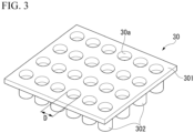
- FIG. 3 is a schematic perspective view illustrating the adhesion portion 30.
- the adhesion portion 30 includes a plate-shaped base portion 301 with a plurality of holes 30a and wells 302 provided to cover the lower part of the hole 30a.
- the well 302 is a recess portion covered with a wall portion and a bottom portion and open at the hole 30a.
- the adhesion portion 30 is a so-called well plate in which a plurality of wells are arranged in a matrix shape at equal intervals.
- the well plate is known to have a configuration in which the number of wells is 6 (6 wells), 12 (12 wells), 24 (24 wells), 48 (48 wells), and 96 (96 wells).
- the opening diameter D of the holes 30a varies depending on the shape of the wells 302, but is set to substantially 6.5 mm to 7.0 mm.
- the liquid droplet forming apparatus 1 can eject liquid droplets in a state in which the ejection head 110 is inserted into the well.
- the adhesion portion 30 is mounted on the mounting portion 40.
- the mounting portion 40 includes an x-stage 41, a y-stage 42, and a base 43.
- the x-stage 41 supports and fixes the adhesion portion 30. Further, the x-stage 41 moves the adhesion portion 30 horizontally in the x-axis direction.
- the y-stage 42 moves the x-stage 41 horizontally in the y-axis direction.
- the base 43 supports the y-stage 42.
- the mounting portion 40 can employ a known configuration as the x and y stages.
- the control unit 50 generates an electrical signal for operating each portion of the liquid droplet forming apparatus 1, and supplies and controls each portion. For example, the control unit 50 generates drive signals to be supplied to the ejecting portion 10 and the mounting portion 40, and supplies the drive signals to each portion to control the operation of each portion.
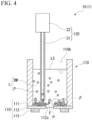
- FIGS. 4 and 5 are explanatory views illustrating an operation of the liquid droplet forming apparatus 1.
- the particles P accumulated on the bottom surface 110x are dispersed in the liquid L before the liquid droplets are ejected, and then the liquid droplet ejection is performed.
- the posture controller inserts the nozzle 121 of the stirrer 120 into the liquid chamber 110A based on a control signal supplied from the control unit 50. At this time, the tip of the nozzle 121 may be brought close to the bottom surface 110x without coming into contact with the bottom surface 110x.
- the tip of the nozzle 121 is brought closer to the bottom surface 110x to the same extent as the opening diameter of the nozzle 121.
- the tip of the nozzle 121 may be brought closer to a position 0.6 mm above the bottom surface 110x.
- the shape of the opening portion 121x (see FIG. 2 ) of the nozzle 121 is not a circular shape, the smallest rectangle that circumscribes the opening portion 121x is assumed, and the length of a short side of the rectangle is used as a determination criterion.
- the shape of the opening portion 121x is an elliptical shape
- the moving unit 130 controls the position where the stirrer 120 sucks or discharges the liquid L in the liquid chamber 110A, specifically, the position of the nozzle 121 in the liquid chamber 110A.
- the stirrer 120 sucks the liquid L in the liquid chamber 110A from the nozzle 121 based on the control signal supplied from the control unit 50.
- the suction amount of the liquid L by the stirrer 120 is preferably an amount by which a liquid surface LS of the liquid L in the liquid chamber 110A does not fall downward (on the bottom surface 110x side) below the opening portion 121x.
- the position of the height position of the liquid level LS is not equal to or lower than 1 mm from the bottom surface 110x.
- the control unit 50 calculates a suction amount that satisfies the position of the liquid level LS, based on a liquid feeding amount per unit time by the liquid feeding portion 122 and the amount of the liquid L stored in the liquid chamber 110A. Alternatively, the control unit 50 stores the calculated suction amount described above. The control unit 50 can cause the stirrer 120 to perform a suction operation in which these suction amounts are satisfied.
- the stirrer 120 discharges the sucked liquid L into the liquid chamber 110A based on the control signal supplied from the control unit 50.
- the liquid L discharged from the nozzle 121 forms a flow F of the liquid L and winds up the particles P accumulated on the bottom surface 110x facing the opening portion 121x.
- the liquid L in the liquid chamber 110A is stirred.
- control unit 50 performs control such that the set value of the liquid feeding amount at the time of discharge does not exceed the set value of the liquid feeding amount at the time of suction.
- the moving unit 130 moves the stirrer 120 based on the control signal supplied from the control unit 50 and moves the position of the nozzle 121 in the liquid chamber 110A.
- the position of the nozzle 121 after the movement can be the same as the description in FIG. 4 .
- the stirrer 120 sucks and discharges the liquid L in the liquid chamber 110A from the nozzle 121 based on the control signal supplied from the control unit 50.
- the operation of suction and discharge of the liquid L can be the same as described in FIG. 4 . Accordingly, the liquid L discharged from the nozzle 121 winds up the particles P accumulated on the bottom surface 1 10x, and the liquid L in the liquid chamber 110A is stirred. The operation of suction and discharge of the liquid L by the stirrer 120 is performed before the dispersed particles P in FIG. 4 are accumulated on the bottom surface 110x again.
- the discharging amount smaller than the suction amount in the first suction and discharge operation and to hold the liquid L in the stirrer 120.
- the suction amount and the discharging amount of the liquid L are controlled to be the same amount in the second and subsequent suction and discharge operations in a state in which the stirrer 120 holds the liquid L, there is no concern about discharging air bubbles into the liquid L at the time of discharge of the liquid L, and the operation is stable.
- the control unit 50 causes the stirrer 120 to suck and discharge the liquid L at a plurality of places in the liquid chamber 110A.
- the control unit 50 preferably stirs the liquid L in the entire liquid chamber 110A by sucking and discharging the liquid L at the center of the bottom surface 110x, which has a circular shape in plan view, and at the plurality of places (for example, 4 places every 90° in the circumferential direction) equally spaced around the center of the bottom surface 110x.
- the order in which the suction and discharge of the liquid L is performed can be appropriately set.
- the position where the liquid L is sucked and discharged by the stirrer 120 is not limited to the position described above and can be appropriately changed according to the shape or size of the liquid chamber 110A.
- the stirrer 120 can eliminate the accumulation of the particles P on the bottom surface 110x, disperse the particles P, and stir the liquid L.
- the control unit 50 supplies the control signal to the moving unit 130 and extracts the nozzle 121 from the liquid chamber 110A before the ejection head 110 ejects the liquid L. Thereafter, the ejection head 110 ejects the liquid L.
- the nozzle plate 112 vibrates in the ejection head 110, and, together, the liquid L in the liquid holding portion 111 or the liquid chamber 110A vibrates.
- the nozzle 121 also vibrates, and there is a concern that the vibration characteristics of the nozzle 121 may affect the formation of the liquid droplets.
- the formation of liquid droplets can be easily stabilized.
- the liquid L held in the liquid chamber 110A is stirred and the particles P are suitably dispersed. Therefore, according to the liquid droplet forming apparatus 1 configured as described above, it is possible to stably eject the dispersion liquid, as liquid droplets, containing the settling particles having constant concentration.
- FIGS. 6 to 8 are explanatory views of a liquid droplet forming apparatus 2 according to a second embodiment of the present invention.
- the same reference symbols are given to the same component elements as in the first embodiment, and detailed description thereof will be omitted.
- FIG. 6 is a schematic view of a configuration of a part of the ejecting portion 20 included in the liquid droplet forming apparatus 2 of the present embodiment and is a view corresponding to FIG. 2 .
- the ejecting portion 20 includes an ejection head 110, stirrer 220, and moving unit 230.
- the ejecting portion 20 may further have the same configuration as the moving unit 130 of the first embodiment.
- the stirrer 220 includes a nozzle (tube-like member) 221 and a liquid feeding portion 122 and stirs the liquid L held in the liquid chamber 110A.
- the nozzle 221 is inserted into the liquid chamber 110A.
- the liquid feeding portion 122 sucks or discharges the liquid L stored in the liquid chamber 110A via the nozzle 121.
- the nozzle 221 is a tube-shaped member forming a flow path of the liquid L in the liquid chamber 110A, and the tip 221a is formed as a surface obliquely intersecting a central axis of the nozzle 221. Accordingly, the opening portion 221x of the nozzle 221 is open in a direction intersecting the central axis of the nozzle 221.
- the moving unit 230 rotates the stirrer 220 around the central axis of the nozzle 221. As a result, the moving unit 230 changes an orientation of the opening portion 221x in the liquid chamber 110A in the circumferential direction of the central axis of the nozzle 221.
- the moving unit 230 may rotate the entire stirrer 220 or may rotate only the nozzle 221.
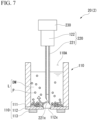
- FIGS. 7 and 8 are explanatory views illustrating an operation of the liquid droplet forming apparatus 2.
- the moving unit 130 inserts the nozzle 221 of the stirrer 220 into the liquid chamber 110A based on the control signal supplied from the control unit 50.
- the moving unit 130 positions the tip of the nozzle 221 at the center of the bottom surface 110x in plan view.
- the opening portion 221x of the nozzle 221 is open in a direction intersecting the central axis of the nozzle 221. Therefore, in the nozzle 221 positioned at the center of the bottom surface 110x, the opening portion 221x is open toward the corner of the bottom surface 110x instead of the center of the bottom surface 110x.
- the stirrer 220 sucks and discharges the liquid L in the liquid chamber 110A from the nozzle 221 based on the control signal supplied from the control unit 50.
- the liquid L discharged from the nozzle 221 forms a flow F of the liquid L and winds up the particles P accumulated on the bottom surface 110x facing the opening portion 221x. As a result, the liquid L in the liquid chamber 110A is stirred.
- the moving unit 230 which is the posture controller, rotates the stirrer 220 based on the control signal supplied from the control unit 50 and changes the opening direction of the nozzle 221 in the liquid chamber 110A.
- the moving unit 230 controls a direction in which the stirrer 220 sucks or discharges the liquid L in the liquid chamber 110A, specifically, an opening direction of the opening portion 221x of the nozzle 221 in the liquid chamber 110A.
- the stirrer 220 sucks and discharges the liquid L in the liquid chamber 110A from the nozzle 221 based on the control signal supplied from the control unit 50.
- the operation of suction and discharge of the liquid L can be the same as described in FIG. 4 . Accordingly, the liquid L discharged from the nozzle 221 winds up the particles P accumulated on the bottom surface 1 10x, and the liquid L in the liquid chamber 110A is stirred.
- the control unit 50 causes the stirrer 220 to suck and discharge the liquid L in a plurality of directions in the liquid chamber 110A.
- the control unit 50 preferably stirs the liquid L in the entire liquid chamber 110A by sucking and discharging the liquid L in the plurality of directions (for example, 4 directions every 90° in the circumferential direction) equally spaced around the center of the bottom surface 110x.
- the order in which the suction and discharge of the liquid L is performed can be appropriately set.
- the direction in which the liquid L is sucked and discharged by the stirrer 220 can be appropriately changed according to the shape or size of the liquid chamber 110A.
- the stirrer 220 can eliminate the accumulation of the particles P on the bottom surface 110x, disperse the particles P, and stir the liquid L.
- the control unit 50 supplies the control signal to the moving unit 130 and extracts the nozzle 221 from the liquid chamber 110A before the ejection head 110 ejects the liquid L. Thereafter, the ejection head 110 ejects the liquid L.
- the liquid L held in the liquid chamber 110A is stirred and the particles P are suitably dispersed. Therefore, according to the liquid droplet forming apparatus 2 configured as described above, it is possible to stably eject the dispersion liquid, as liquid droplets, containing the settling particles having constant concentration.
- the posture controller controls any one of the position and the direction where the stirrer sucks and discharges the liquid L in the liquid chamber 110A
- the present embodiment is not limited to this.
- the tip position of the nozzle 221 may be changed in the liquid chamber 110A using the moving unit 130 without fixing the tip position of the nozzle 221 to the center of the bottom surface 110x in plan view.
- the stirrer discharges the liquid L in the same posture (nozzle position and nozzle opening direction) as when the liquid L is sucked
- the present embodiment is not limited to this.
- the posture of the stirrer may be changed by the posture controller, and then the stirrer may discharge the liquid L.
- the orientation of the opening portion 221x of the nozzle 221 may be changed by the moving unit 230 while the stirrer sucks and discharges the liquid L. Even in a case where the liquid droplet forming apparatus performs such an operation, the effect of the present invention can be exhibited.
- the present invention includes the following aspects.
Landscapes
- Coating Apparatus (AREA)
- Ink Jet (AREA)
- Apparatus Associated With Microorganisms And Enzymes (AREA)
Abstract
Description
- The present application claims priority under 35 U.S.C. § 119 to
Japanese Patent Application No. 2023-049895, filed Mar. 27, 2023 - The present invention relates to a liquid droplet forming apparatus.
- In the related art, an inkjet type liquid droplet forming apparatus is known as a technique for ejecting a liquid substance (liquid) such as ink to a desired position.
- In recent years, there has been demand for a liquid droplet forming apparatus which can eject various types of liquid in place of ink used in two-dimensional printing in the related art. Exemplary examples of the liquid to be ejected include dispersion liquid as well as a solution. Exemplary examples of dispersoids (particles) contained in the dispersion liquid include organic materials such as resin materials, inorganic materials such as metal particles and oxide particles, and biologically derived materials such as cells and genes.
- In a case where the above-described dispersion liquid is ejected in a liquid droplet forming apparatus, dispersoids may settle in a liquid chamber. In the following description, the dispersoids that settle in the dispersion liquid may be referred to as "settling particles". In a case where settling particles settle, the concentration of settling particles contained in the liquid to be ejected changes even in a case where the amount of liquid droplets to be ejected is constant, which makes it difficult to stably eject a desired amount of dispersoids.
- In response to such a problem in the related art, in a liquid droplet forming apparatus that stores dispersion liquid containing settling particles, a configuration having two liquid suction-discharge members connected to a liquid holding portion has been proposed (for example, see
Japanese Patent No. 7062974 Japanese Patent No. 7062974 - In the configuration of
Japanese Patent No. 7062974 - The present invention has been made in view of such circumstances, and an object of the present invention is to provide a liquid droplet forming apparatus capable of stably ejecting dispersion liquid, as liquid droplets, containing settling particles having constant concentration.
- In order to solve the above problems, one aspect of the present invention provides a liquid droplet forming apparatus including: an ejection head that has a liquid chamber storing liquid containing settling particles and that ejects a liquid droplet of the liquid; stirrer for stirring the liquid held in the liquid chamber; posture controller for controlling a posture of the stirrer; and a control unit that controls operations of the ejection head, the stirrer, and the posture controller, in which the stirrer includes a tube-like member inserted into the liquid chamber, and a liquid feeding portion that sucks or discharges the liquid stored in the liquid chamber via the tube-like member, and the posture controller controls one or both of the position and the direction in which the stirrer sucks and discharges the liquid in the liquid chamber.
- In the present invention, it is possible to provide a liquid droplet forming apparatus capable of stably ejecting dispersion liquid, as liquid droplets, containing settling particles having constant concentration.
-
-
FIG. 1 is a schematic view of a liquiddroplet forming apparatus 1 of a first embodiment. -
FIG. 2 is a schematic view illustrating a configuration of a part of an ejectingportion 10. -
FIG. 3 is a schematic perspective view illustrating anadhesion portion 30. -
FIG. 4 is an explanatory view illustrating an operation of the liquiddroplet forming apparatus 1. -
FIG. 5 is an explanatory view illustrating an operation of the liquiddroplet forming apparatus 1. -
FIG. 6 is a schematic view of a liquiddroplet forming apparatus 2 of a second embodiment. -
FIG. 7 is an explanatory view illustrating an operation of the liquiddroplet forming apparatus 2. -
FIG. 8 is an explanatory view illustrating an operation of the liquiddroplet forming apparatus 2. - A liquid droplet forming apparatus according to a first embodiment of the present invention will be described below with reference to
FIGS. 1 to 5 . In all the following drawings, dimensions, proportions, and the like of each constituent element have been appropriately changed in order to make the drawings easier to see. -
FIG. 1 is a schematic view of a liquiddroplet forming apparatus 1 of the present embodiment. As illustrated inFIG. 1 , the liquiddroplet forming apparatus 1 includes an ejectingportion 10, anadhesion portion 30, amounting portion 40, and acontrol unit 50.FIG. 2 is a schematic view illustrating a configuration of a part of the ejectingportion 10. - In the following description, an xyz orthogonal coordinate system is set, and a positional relationship of each member will be described with reference to the xyz orthogonal coordinate system. Here, a predetermined direction within a horizontal plane is defined as an x-axis direction, a direction orthogonal to the x-axis direction within the horizontal plane is defined as a y-axis direction, and a direction (that is, a vertical direction) orthogonal to each of the x-axis direction and the y-axis direction is defined as a z-axis direction.
- In addition, an upper part in the vertical direction is defined as a +z direction, and a lower part in the vertical direction is defined as a -z direction. In the following description, the same meanings are applied to the term "up" from "upper part" and "upper surface" and the term "low" from "lower part" and "lower surface".
- Further, in the following description, the term "plan view" refers to viewing a target object from above, and the term "planar shape" refers to a shape of the target object as viewed from above.
- As illustrated in
FIGS. 1 and2 , the ejectingportion 10 includes anejection head 110, stirrer 120, and movingunit 130. The movingunit 130 corresponds to posture controller in the present invention. - The
ejection head 110 ejects a liquid droplet L1 of liquid containing settling particles. The ejectingportion 10 may include only oneejection head 110 or a plurality ofejection heads 110. - The
ejection head 110 includes aliquid holding portion 111, a nozzle plate (film-like member) 112, and vibration applier 113. - A space surrounded by the
liquid holding portion 111, thenozzle plate 112, and the vibration applier 113 is aliquid chamber 110A of theejection head 110. The liquid (liquid L) containing settling particles is held in theliquid chamber 110A. - The amount of the liquid L held in the
liquid chamber 110A is not particularly limited. Exemplary examples of the amount of the liquid L held in theliquid chamber 110A include substantially 1 µl to 1 ml. When expensive liquid such as cell suspension is ejected from the liquiddroplet forming apparatus 1, it is preferable that the amount of the liquid L held in theliquid chamber 110A is substantially 1 µl to 200 µl. - The liquid L ejected by the liquid
droplet forming apparatus 1 contains dispersoids (particles P), which are settling particles, and a dispersion medium DM in which the particles P are dispersed. - Exemplary examples of the particles P include organic materials such as polymer particles, and inorganic materials such as fine metal particles and inorganic oxide particles. Exemplary examples of the fine metal particles include silver particles and copper particles. Exemplary examples of the inorganic fine particles include titanium oxide particles and silicon oxide particles.
- Further, cells can also be used as the particles P. As the cells, plant cells or animal cells can be applied. Exemplary examples of the animal cells include, particularly, human-derived cells.
- Exemplary examples of the dispersion medium DM include water and alcohol. The dispersion medium DM may contain a wetting agent for suppressing evaporation or a surfactant for lowering surface tension.
- In the present embodiment, the liquid L ejected by the liquid
droplet forming apparatus 1 will be described as dispersion liquid in which cells are dispersed as the particles P in the dispersion medium DM. In this case, as the dispersion medium DM, known buffer solutions such as phosphate buffered saline or Hank's balanced salt solution, or various cell culture media can be used. - The
liquid holding portion 111 is a tubular-shaped member of which both end portions are open in the z-axis direction. Exemplary examples of the material of theliquid holding portion 111 include metal, silicon, ceramics, and polymer materials. In the liquiddroplet forming apparatus 1 that ejects the liquid L in which cells are dispersed, a material to which cells are not easily adhered is preferable as a material of theliquid holding portion 111. As such a material, a material having high hydrophilicity is preferable. - Exemplary examples of such materials include metal, ceramics, semiconductor materials, and polymer materials. A fluororesin can be used as the polymer material.
- A lower end portion of the
liquid holding portion 111 is blocked by thenozzle plate 112 and thevibration applier 113. It is preferable that, in a case where cells are used as the particles P, an upper end portion of theliquid holding portion 111 is open. When the upper part of theliquid holding portion 111 is open, the liquid L held in theliquid holding portion 111 is less likely to be pressurized during liquid droplet ejection, and damage to cells can be suppressed. - As the
liquid holding portion 111, for example, a member having a cylindrical shape, a truncated cone shape, or a square tubular shape can be used. - The size of the
liquid holding portion 111 can be selected according to the shape of theadhesion portion 30 described below. For example, in a case where a known 96 well plate is used as theadhesion portion 30, a cylindrical-shaped member having an outer diameter of 6.0 mm or less can be used as the liquid holding portion. In this case, for example, the inner diameter of theliquid holding portion 111 can be set to 4 mm, and the height can be set to 10 mm. - The volume of the
liquid holding portion 111 is not particularly limited and may be appropriately selected according to the purposes. - The
nozzle plate 112 is a ring-shaped member having anejection outlet 112x. Thenozzle plate 112 blocks the lower end portion of theliquid holding portion 111 and forms theliquid chamber 110A, which holds the liquid L, together with theliquid holding portion 111. An upper surface of thenozzle plate 112 is abottom surface 110x of theliquid chamber 110A. Theejection outlet 112x communicates with theliquid holding portion 111. - The planar shape, the size when viewed in a plan view, the material, and the structure of the
nozzle plate 112 are not particularly limited and can be appropriately selected according to the purpose. - Exemplary examples of the planar shape of an outer edge of the
nozzle plate 112 include a circular shape, an elliptical shape, a rectangular shape, a square shape, and a rhombic shape. For example, in a case where the shape of the outer edge of thenozzle plate 112 is a circular shape, thenozzle plate 112 is a circular ring-shaped member. - The
nozzle plate 112 is not supported at an end portion on anejection outlet 112x side and is capable of vibrating up and down (z-axis direction). Thenozzle plate 112 vibrates at the end portion on theejection outlet 112x side to apply a downward force to the liquid L in the vicinity of theejection outlet 112x, and the liquid L is ejected from theejection outlet 112x as the liquid droplet L1. - As the material of the
nozzle plate 112, it is preferable to use a material having a certain degree of hardness because thenozzle plate 112 may easily vibrate and it may be difficult to immediately suppress the vibration when thenozzle plate 112 is not in the ejection state, in a case where thenozzle plate 112 is too soft. - Further, in a case where the liquid L to be ejected is dispersion liquid of cells, the material of the
nozzle plate 112 is preferably a material to which cells do not easily adhere. As such a material, a material having high hydrophilicity is preferable. - Exemplary examples of such materials include metal, ceramics, semiconductor materials, and polymer materials. A fluororesin can be used as the polymer material.
- More specifically, exemplary examples of the material of the
nozzle plate 112 include stainless steel, nickel, aluminum, silicon dioxide, alumina, and zirconia. Further, it is possible to use a composite material in which a surface of thenozzle plate 112, which is formed with a material different from the above material, is coated with the above-described metal, ceramics, or a synthetic phospholipid polymer (for example, Lipidure, manufactured by NOF Corporation) that mimics the cell membrane. - The opening shape of the
ejection outlet 112x can be appropriately selected according to the purpose. Exemplary examples of the opening shape of theejection outlet 112x include a circular shape, an elliptical shape, and a square shape. Among them, a circular shape is preferable as the opening shape of theejection outlet 112x. - The average opening diameter of the
ejection outlet 112x is not particularly limited and can be appropriately selected according to the purpose. In order to prevent clogging of theejection outlet 112x by the dispersoids such as cells dispersed in the liquid L in a case where the liquid L to be ejected is dispersion liquid, it is preferable for the opening shape of theejection outlet 112x to be at least twice the maximum diameter of the dispersoid. - The
nozzle plate 112 having a relatively large diameter (for example, 100 µm) of theejection outlet 112x also has a large diameter of the liquid droplets to be ejected. Such anozzle plate 112 is suitable for a case where a large amount of liquid needs to be dispensed because a large amount of liquid can be ejected with a small number of liquid droplets. - On the other hand, the
nozzle plate 112 having a relatively small diameter of theejection outlet 112x has a relatively small diameter of the liquid droplets to be ejected. Such anozzle plate 112 is suitable for the purpose of precisely controlling the number of cells to dispense the cells. - The
vibration applier 113 vibrates thenozzle plate 112 based on an electrical signal to be input, thereby ejecting the liquid droplet L1 from theejection outlet 112x. - The
vibration applier 113 is installed on a lower surface of thenozzle plate 112. - The shape, the size, the material, and the structure of the
vibration applier 113 are not particularly limited and can be appropriately selected according to the purpose. - The shape or the disposition of the
vibration applier 113 are not particularly limited as long as the effects of the invention are not impaired, and can be appropriately designed in accordance with the shape of thenozzle plate 112. For example, in a case where the planar shape of thenozzle plate 112 is a circular ring shape, it is preferable to provide thevibration applier 113 concentrically around theejection outlet 112x. - A piezoelectric element is suitably used as the
vibration applier 113. As the piezoelectric element, for example, it is possible to employ a structure in which electrodes for applying voltage are provided on an upper surface and a lower surface of a piezoelectric material. - In this case, by applying voltage between the upper and lower electrodes of the piezoelectric element through the
control unit 50, compressive stress is applied in a lateral direction of a film surface so that it is possible to vibrate thenozzle plate 112 in the up and down direction of the film surface. - The piezoelectric material is not particularly limited and can be appropriately selected according to the purpose, and exemplary examples thereof include lead zirconate titanate (PZT), bismuth iron oxide, metal niobate, barium titanate, and composites of these materials with metals or different oxides. Among them, lead zirconate titanate (PZT) is preferable.
- Further, the
vibration applier 113 may be a heater made of a material having a linear expansion coefficient different from that of the material of thenozzle plate 112. Such a heater may be patterned on thenozzle plate 112, and the heater may be energized and heated to generate vibration. - The
stirrer 120 includes a nozzle (tube-like member) 121 and aliquid feeding portion 122 and stirs the liquid L held in theliquid chamber 110A. Thenozzle 121 is inserted into theliquid chamber 110A. Theliquid feeding portion 122 sucks or discharges the liquid L stored in theliquid chamber 110A via thenozzle 121. - The
nozzle 121 is a tube-shaped member that constitutes a flow path of the liquid L in theliquid chamber 110A and includes anopening portion 121x at the tip. The outer diameter of thenozzle 121 is smaller than the inner diameter of theliquid holding portion 111, and can be, for example, set to 1/2 or less of the inner diameter of theliquid holding portion 111. For example, in a case where a cylindrical-shaped member having an inner diameter of 2.8 mm is used as theliquid holding portion 111, a tube with an outer diameter of 0.8 mm can be used as thenozzle 121. - The material of the
nozzle 121 is not particularly limited, and thenozzle 121 can be formed using a resin, a silicon rubber, a metal, or the like. It is preferable to use a general-purpose resin-made thin tube called a disposable tip as thenozzle 121 because replacement is easy. - The
liquid feeding portion 122 is a pump that sucks or discharges the liquid L in theliquid chamber 110A via thenozzle 121. A syringe pump or a diaphragm pump can be employed as theliquid feeding portion 122 in theliquid feeding portion 122. - According to
such stirrer 120, the liquid L in theliquid chamber 110A can be stirred by inserting thenozzle 121 into theliquid chamber 110A and sucking or discharging the liquid L in theliquid chamber 110A. - The moving
unit 130 includes afirst movement portion 131, asecond movement portion 132, athird movement portion 133, a first conveyingportion 134, and a second conveyingportion 135. The movingunit 130, which is posture controller, controls a posture of thestirrer 120. The "posture" of thestirrer 120 is specifically a relative posture of thestirrer 120 with respect to theliquid chamber 110A of theejection head 110. By controlling the posture of thestirrer 120, one or both of the position of thenozzle 121 of thestirrer 120 and the opening direction of thenozzle 121 are controlled. The movingunit 130 controls the posture of thestirrer 120 and controls the position and opening direction of thenozzle 121. - As illustrated in
FIG. 1 , thefirst movement portion 131 includes asupport member 131a and alinear motion portion 131b. - The
support member 131a supports theejection head 110 in an attachable and detachable manner. Therefore, when theejection head 110 is contaminated or damaged, theejection head 110 can be removed from thesupport member 131a and replaced with anew ejection head 110. - The
linear motion portion 131b is an elongated member that is connected to thesupport member 131a and extends in the z-axis direction. Thelinear motion portion 131b moves thesupport member 131a up and down. Thelinear motion portion 131b can employ, for example, a known linear actuator including a stepping motor as a drive source. - The
linear motion portion 131b may include an encoder that determines a drive amount of the stepping motor and may be configured to be capable of determining a movement amount of thesupport member 131a. - The
first movement portion 131 moves thesupport member 131a up and down by driving thelinear motion portion 131b. Accordingly, thefirst movement portion 131 moves theejection head 110 supported by thesupport member 131a up and down. Specifically, thefirst movement portion 131 moves theejection head 110 to a non-ejection position where the liquid L is not ejected from theejection head 110 and an ejection position where the liquid is ejected from theejection head 110.FIG. 1 illustrates the ejection head 110 (110A) positioned at the non-ejection position and the ejection head 110 (110B) positioned at the ejection position. - The
second movement portion 132 includes asupport member 132a and alinear motion portion 132b. Thesecond movement portion 132 is a pair of members provided at end portions of the first conveyingportion 134 on the +x side and the -x side. - The
support member 132a is a rectangular member in the field of view when viewed from the +y direction and supports thefirst movement portion 131. - The
linear motion portion 132b is an elongated member extending in the z-axis direction. Thelinear motion portion 132b moves thesupport member 132a up and down in the z-axis direction. Thelinear motion portion 132b can employ, for example, a known linear actuator including a stepping motor as a drive source. - The
second movement portion 132 moves thesupport member 132a in the z-axis direction, thereby moving theejection head 110 supported by thefirst movement portion 131 in the z-axis direction. - The
third movement portion 133 includes asupport member 133a and alinear motion portion 133b. - The
support member 133a supports thestirrer 120 in an attachable and detachable manner. Therefore, when thestirrer 120 is contaminated or damaged, thestirrer 120 can be removed from thesupport member 133a and replaced withnew stirrer 120. - The
linear motion portion 133b is an elongated member extending in the z-axis direction and moves thesupport member 133a up and down. Thelinear motion portion 133b can employ, for example, a known linear actuator including a stepping motor as a drive source. - The
linear motion portion 133b may include an encoder that determines a drive amount of the stepping motor and may be configured to be capable of determining a movement amount of thesupport member 133a. - The
third movement portion 133 moves thesupport member 133a up and down by driving thelinear motion portion 133b. Accordingly, thethird movement portion 133 moves thestirrer 120 supported by thesupport member 133a up and down. - The first conveying
portion 134 includes asupport member 134a and alinear motion portion 134b. - The
support member 134a is a rectangular member in the field of view when viewed from the +y direction and supports theejection head 110 via thefirst movement portion 131. - The
linear motion portion 134b is an elongated member extending in the x-axis direction. Thelinear motion portion 134b moves thesupport member 134a horizontally in the x-axis direction. Both ends of thelinear motion portion 134b are each supported by thesupport member 132a of thesecond movement portion 132. - The
linear motion portion 134b can employ, for example, a known linear actuator including a stepping motor as a drive source. - The first conveying
portion 134 moves thesupport member 134a in the x-axis direction, thereby moving theejection head 110 supported by thesupport member 134a in the x-axis direction. - The second conveying
portion 135 includes asupport member 135a and alinear motion portion 135b. - The
support member 135a is a rectangular member in the field of view when viewed from the +y direction and supports thestirrer 120 via thethird movement portion 133. - The
linear motion portion 135b is an elongated member extending in the x-axis direction. Thelinear motion portion 135b moves thesupport member 134a horizontally in the x-axis direction. Thelinear motion portion 135b can employ, for example, a known linear actuator including a stepping motor as a drive source. - The second conveying
portion 135 moves thesupport member 135a in the x-axis direction, thereby moving thestirrer 120 supported by thesupport member 135a in the x-axis direction. - Further, the moving
unit 130 is provided with a mechanism that controls a posture of thestirrer 120 in the y-axis direction (the relative posture of thestirrer 120 with respect to theliquid chamber 110A). - Such a configuration can be realized, for example, by making the
support member 132a of thesecond movement portion 132 movable in the y-axis direction. Similarly, such a configuration can be realized by making indicating members (not illustrated) that support thelinear motion portion 135b of the second conveyingportion 135 on both sides in the x-axis direction movable in the y-axis direction. - Further, a configuration may be used in which the
support member 134a is moved in the y-axis direction and theejection head 110 supported by thesupport member 134a is moved in the y-axis direction, or a configuration may be used in which thesupport member 135a is moved in the y-axis direction and thestirrer 120 supported by thesupport member 135a is moved in the y-axis direction. - When the moving
unit 130 has these configurations, the posture of thenozzle 121 in the y-axis direction with respect to theliquid chamber 110A can be controlled. - The
adhesion portion 30 is disposed in the ejection direction of the liquid droplet L1 ejected from the ejectingportion 10, and the liquid droplet L1 adheres thereto. As theadhesion portion 30, it is possible to select a structure object having various materials and shapes according to the purpose of ejecting the liquid. -
FIG. 3 is a schematic perspective view illustrating theadhesion portion 30. Theadhesion portion 30 includes a plate-shapedbase portion 301 with a plurality ofholes 30a andwells 302 provided to cover the lower part of thehole 30a. The well 302 is a recess portion covered with a wall portion and a bottom portion and open at thehole 30a. - The
adhesion portion 30 is a so-called well plate in which a plurality of wells are arranged in a matrix shape at equal intervals. - In a case where such an
adhesion portion 30 is used, when ejection head is disposed an upper part of thebase portion 301 of theadhesion portion 30 and the liquid is ejected, the distance between the bottom of the well to which the liquid is adhered and the ejection head is large, and the position at which the liquid is adhered tends to shift. - Further, commercially available well plates have various variations with different numbers of wells. For example, the well plate is known to have a configuration in which the number of wells is 6 (6 wells), 12 (12 wells), 24 (24 wells), 48 (48 wells), and 96 (96 wells).
- In the 96-well plate, which is the largest number, the opening diameter D of the
holes 30a varies depending on the shape of thewells 302, but is set to substantially 6.5 mm to 7.0 mm. By using a cylindrical-shaped member having an outer diameter of 6.0 mm or less as theliquid holding portion 111 of theejection head 110, the liquiddroplet forming apparatus 1 can eject liquid droplets in a state in which theejection head 110 is inserted into the well. - The
adhesion portion 30 is mounted on the mountingportion 40. The mountingportion 40 includes an x-stage 41, a y-stage 42, and abase 43. - The x-stage 41 supports and fixes the
adhesion portion 30. Further, the x-stage 41 moves theadhesion portion 30 horizontally in the x-axis direction. - The y-
stage 42 moves the x-stage 41 horizontally in the y-axis direction. - The
base 43 supports the y-stage 42. - The mounting
portion 40 can employ a known configuration as the x and y stages. - The
control unit 50 generates an electrical signal for operating each portion of the liquiddroplet forming apparatus 1, and supplies and controls each portion. For example, thecontrol unit 50 generates drive signals to be supplied to the ejectingportion 10 and the mountingportion 40, and supplies the drive signals to each portion to control the operation of each portion. - Hereinafter, a characteristic operation of the liquid
droplet forming apparatus 1 will be described with reference to the drawings.FIGS. 4 and5 are explanatory views illustrating an operation of the liquiddroplet forming apparatus 1. - As illustrated in
FIG. 4 , when a time elapses after theliquid holding portion 111 is filled with the liquid L, there is a case where the particles P settle and are accumulated on thebottom surface 110x of theliquid chamber 110A. When the liquid droplet ejection is started in such a state, the particles P, which are accumulated on thebottom surface 110x (seeFIG. 2 ), especially near theejection outlet 112x (indicated by a symbol α in the figure), are ejected at once, and the liquid droplet ejection becomes difficult in a state where the number of particles is controlled. - Further, even when a certain amount of liquid droplets are ejected in a state where the particles P have settled and the particles P at the position indicated by the symbol α are removed, the particles P tend to remain at the corner of the
bottom surface 110x, specifically at a position where theliquid holding portion 111 and thenozzle plate 112 intersect (indicated by a symbol β in the figure). Therefore, when the liquid droplets are continuously ejected, there is a concern that the particles P at the position indicated by the symbol β may be mixed with the liquid droplets, and the droplet ejection becomes difficult in a state where the number of particles is controlled. - Therefore, in the liquid
droplet forming apparatus 1, the particles P accumulated on thebottom surface 110x are dispersed in the liquid L before the liquid droplets are ejected, and then the liquid droplet ejection is performed. - First, as illustrated in
FIG. 4 , the posture controller (the moving unit 130) inserts thenozzle 121 of thestirrer 120 into theliquid chamber 110A based on a control signal supplied from thecontrol unit 50. At this time, the tip of thenozzle 121 may be brought close to thebottom surface 110x without coming into contact with thebottom surface 110x. - Specifically, it is preferable that the tip of the
nozzle 121 is brought closer to thebottom surface 110x to the same extent as the opening diameter of thenozzle 121. For example, when the inner diameter of thenozzle 121 is 0.6 mm, the tip of thenozzle 121 may be brought closer to a position 0.6 mm above thebottom surface 110x. In a case where the shape of theopening portion 121x (seeFIG. 2 ) of thenozzle 121 is not a circular shape, the smallest rectangle that circumscribes theopening portion 121x is assumed, and the length of a short side of the rectangle is used as a determination criterion. For example, in a case where the shape of theopening portion 121x is an elliptical shape, it is preferable to bring the tip of thenozzle 121 close to a position above thebottom surface 110x by the length of the short side of the rectangle circumscribing theopening portion 121x (that is, the length of the short axis of the ellipse). - As a result, the moving
unit 130 controls the position where thestirrer 120 sucks or discharges the liquid L in theliquid chamber 110A, specifically, the position of thenozzle 121 in theliquid chamber 110A. - Next, the
stirrer 120 sucks the liquid L in theliquid chamber 110A from thenozzle 121 based on the control signal supplied from thecontrol unit 50. - The suction amount of the liquid L by the
stirrer 120 is preferably an amount by which a liquid surface LS of the liquid L in theliquid chamber 110A does not fall downward (on thebottom surface 110x side) below theopening portion 121x. For example, in a case where the liquid level LS is at a position with height of 6 mm from thebottom surface 110x and theopening portion 121x is at a position with height of 1 mm from thebottom surface 1 10x, it is preferable that the position of the height position of the liquid level LS is not equal to or lower than 1 mm from thebottom surface 110x. - The
control unit 50 calculates a suction amount that satisfies the position of the liquid level LS, based on a liquid feeding amount per unit time by theliquid feeding portion 122 and the amount of the liquid L stored in theliquid chamber 110A. Alternatively, thecontrol unit 50 stores the calculated suction amount described above. Thecontrol unit 50 can cause thestirrer 120 to perform a suction operation in which these suction amounts are satisfied. - Next, the
stirrer 120 discharges the sucked liquid L into theliquid chamber 110A based on the control signal supplied from thecontrol unit 50. As illustrated inFIG. 4 , the liquid L discharged from thenozzle 121 forms a flow F of the liquid L and winds up the particles P accumulated on thebottom surface 110x facing theopening portion 121x. As a result, the liquid L in theliquid chamber 110A is stirred. - At this time, in a case where a set value of the liquid feeding amount at the time of discharge by the
liquid feeding portion 122 exceeds a set value of the liquid feeding amount at the time of suction by theliquid feeding portion 122, air bubbles are discharged into the liquid L at the time of discharge. Therefore, it is preferable that thecontrol unit 50 performs control such that the set value of the liquid feeding amount at the time of discharge does not exceed the set value of the liquid feeding amount at the time of suction. - Next, as illustrated in
FIG. 5 , the movingunit 130 moves thestirrer 120 based on the control signal supplied from thecontrol unit 50 and moves the position of thenozzle 121 in theliquid chamber 110A. The position of thenozzle 121 after the movement can be the same as the description inFIG. 4 . - Next, the
stirrer 120 sucks and discharges the liquid L in theliquid chamber 110A from thenozzle 121 based on the control signal supplied from thecontrol unit 50. The operation of suction and discharge of the liquid L can be the same as described inFIG. 4 . Accordingly, the liquid L discharged from thenozzle 121 winds up the particles P accumulated on thebottom surface 1 10x, and the liquid L in theliquid chamber 110A is stirred. The operation of suction and discharge of the liquid L by thestirrer 120 is performed before the dispersed particles P inFIG. 4 are accumulated on thebottom surface 110x again. - When the suction and discharge of the liquid L are repeated by the
stirrer 120, it is preferable to make the discharging amount smaller than the suction amount in the first suction and discharge operation and to hold the liquid L in thestirrer 120. In a case where the suction amount and the discharging amount of the liquid L are controlled to be the same amount in the second and subsequent suction and discharge operations in a state in which thestirrer 120 holds the liquid L, there is no concern about discharging air bubbles into the liquid L at the time of discharge of the liquid L, and the operation is stable. - The
control unit 50 causes thestirrer 120 to suck and discharge the liquid L at a plurality of places in theliquid chamber 110A. For example, thecontrol unit 50 preferably stirs the liquid L in the entireliquid chamber 110A by sucking and discharging the liquid L at the center of thebottom surface 110x, which has a circular shape in plan view, and at the plurality of places (for example, 4 places every 90° in the circumferential direction) equally spaced around the center of thebottom surface 110x. - When the suction and discharge of the liquid L is performed at the plurality of places in the
liquid chamber 110A, the order in which the suction and discharge of the liquid L is performed can be appropriately set. - The position where the liquid L is sucked and discharged by the
stirrer 120 is not limited to the position described above and can be appropriately changed according to the shape or size of theliquid chamber 110A. - By repeating these operations, the
stirrer 120 can eliminate the accumulation of the particles P on thebottom surface 110x, disperse the particles P, and stir the liquid L. - In a case where the stirring of the liquid L by the
stirrer 120 is completed, thecontrol unit 50 supplies the control signal to the movingunit 130 and extracts thenozzle 121 from theliquid chamber 110A before theejection head 110 ejects the liquid L. Thereafter, theejection head 110 ejects the liquid L. - When the liquid L is ejected from the
ejection head 110, thenozzle plate 112 vibrates in theejection head 110, and, together, the liquid L in theliquid holding portion 111 or theliquid chamber 110A vibrates. At this time, when thenozzle 121 is inserted into theliquid chamber 110A, thenozzle 121 also vibrates, and there is a concern that the vibration characteristics of thenozzle 121 may affect the formation of the liquid droplets. In the liquiddroplet forming apparatus 1, as described above, by extracting thenozzle 121 from theliquid chamber 110A before the ejection of the liquid droplets, the formation of liquid droplets can be easily stabilized. - Due to these operations, the liquid L held in the
liquid chamber 110A is stirred and the particles P are suitably dispersed. Therefore, according to the liquiddroplet forming apparatus 1 configured as described above, it is possible to stably eject the dispersion liquid, as liquid droplets, containing the settling particles having constant concentration. -
FIGS. 6 to 8 are explanatory views of a liquiddroplet forming apparatus 2 according to a second embodiment of the present invention. In the present embodiment, the same reference symbols are given to the same component elements as in the first embodiment, and detailed description thereof will be omitted. -
FIG. 6 is a schematic view of a configuration of a part of the ejectingportion 20 included in the liquiddroplet forming apparatus 2 of the present embodiment and is a view corresponding toFIG. 2 . - The ejecting
portion 20 includes anejection head 110,stirrer 220, and movingunit 230. In addition, the ejectingportion 20 may further have the same configuration as the movingunit 130 of the first embodiment. - The
stirrer 220 includes a nozzle (tube-like member) 221 and aliquid feeding portion 122 and stirs the liquid L held in theliquid chamber 110A. Thenozzle 221 is inserted into theliquid chamber 110A. Theliquid feeding portion 122 sucks or discharges the liquid L stored in theliquid chamber 110A via thenozzle 121. - The
nozzle 221 is a tube-shaped member forming a flow path of the liquid L in theliquid chamber 110A, and thetip 221a is formed as a surface obliquely intersecting a central axis of thenozzle 221. Accordingly, theopening portion 221x of thenozzle 221 is open in a direction intersecting the central axis of thenozzle 221. - The moving
unit 230 rotates thestirrer 220 around the central axis of thenozzle 221. As a result, the movingunit 230 changes an orientation of theopening portion 221x in theliquid chamber 110A in the circumferential direction of the central axis of thenozzle 221. - The moving
unit 230 may rotate theentire stirrer 220 or may rotate only thenozzle 221. -
FIGS. 7 and8 are explanatory views illustrating an operation of the liquiddroplet forming apparatus 2. - First, as illustrated in
FIG. 7 , the moving unit 130 (seeFIG. 1 ), which is posture controller, inserts thenozzle 221 of thestirrer 220 into theliquid chamber 110A based on the control signal supplied from thecontrol unit 50. For example, the movingunit 130 positions the tip of thenozzle 221 at the center of thebottom surface 110x in plan view. - The
opening portion 221x of thenozzle 221 is open in a direction intersecting the central axis of thenozzle 221. Therefore, in thenozzle 221 positioned at the center of thebottom surface 110x, theopening portion 221x is open toward the corner of thebottom surface 110x instead of the center of thebottom surface 110x. - Next, the
stirrer 220 sucks and discharges the liquid L in theliquid chamber 110A from thenozzle 221 based on the control signal supplied from thecontrol unit 50. The liquid L discharged from thenozzle 221 forms a flow F of the liquid L and winds up the particles P accumulated on thebottom surface 110x facing theopening portion 221x. As a result, the liquid L in theliquid chamber 110A is stirred. - Next, as illustrated in
FIG. 8 , the movingunit 230, which is the posture controller, rotates thestirrer 220 based on the control signal supplied from thecontrol unit 50 and changes the opening direction of thenozzle 221 in theliquid chamber 110A. As a result, the movingunit 230 controls a direction in which thestirrer 220 sucks or discharges the liquid L in theliquid chamber 110A, specifically, an opening direction of theopening portion 221x of thenozzle 221 in theliquid chamber 110A. - Next, the
stirrer 220 sucks and discharges the liquid L in theliquid chamber 110A from thenozzle 221 based on the control signal supplied from thecontrol unit 50. The operation of suction and discharge of the liquid L can be the same as described inFIG. 4 . Accordingly, the liquid L discharged from thenozzle 221 winds up the particles P accumulated on thebottom surface 1 10x, and the liquid L in theliquid chamber 110A is stirred. - The
control unit 50 causes thestirrer 220 to suck and discharge the liquid L in a plurality of directions in theliquid chamber 110A. For example, thecontrol unit 50 preferably stirs the liquid L in the entireliquid chamber 110A by sucking and discharging the liquid L in the plurality of directions (for example, 4 directions every 90° in the circumferential direction) equally spaced around the center of thebottom surface 110x. - When the suction and discharge of the liquid L is performed at the plurality of directions in the
liquid chamber 110A, the order in which the suction and discharge of the liquid L is performed can be appropriately set. - The direction in which the liquid L is sucked and discharged by the
stirrer 220 can be appropriately changed according to the shape or size of theliquid chamber 110A. - By repeating these operations, the
stirrer 220 can eliminate the accumulation of the particles P on thebottom surface 110x, disperse the particles P, and stir the liquid L. - In a case where the stirring of the liquid L by the
stirrer 220 is completed, thecontrol unit 50 supplies the control signal to the movingunit 130 and extracts thenozzle 221 from theliquid chamber 110A before theejection head 110 ejects the liquid L. Thereafter, theejection head 110 ejects the liquid L. - Due to these operations, the liquid L held in the
liquid chamber 110A is stirred and the particles P are suitably dispersed. Therefore, according to the liquiddroplet forming apparatus 2 configured as described above, it is possible to stably eject the dispersion liquid, as liquid droplets, containing the settling particles having constant concentration. - In the above embodiment, although the posture controller controls any one of the position and the direction where the stirrer sucks and discharges the liquid L in the
liquid chamber 110A, the present embodiment is not limited to this. For example, in the liquiddroplet forming apparatus 2 of the second embodiment, the tip position of thenozzle 221 may be changed in theliquid chamber 110A using the movingunit 130 without fixing the tip position of thenozzle 221 to the center of thebottom surface 110x in plan view. - Further, in the above embodiment, although the stirrer discharges the liquid L in the same posture (nozzle position and nozzle opening direction) as when the liquid L is sucked, the present embodiment is not limited to this. For example, after the liquid L is sucked by the stirrer, the posture of the stirrer may be changed by the posture controller, and then the stirrer may discharge the liquid L. Further, in the second embodiment, the orientation of the
opening portion 221x of thenozzle 221 may be changed by the movingunit 230 while the stirrer sucks and discharges the liquid L. Even in a case where the liquid droplet forming apparatus performs such an operation, the effect of the present invention can be exhibited. - As described above, although the preferred examples of the embodiments according to the present invention have been described with reference to the accompanying drawings, the present invention is not limited to such examples. The variety of shapes, combinations, and the like of the individual constituent members described in the above-described examples are examples, and a variety of modifications are permitted based on design requirements and the like without departing from the gist of the present invention.
- The present invention includes the following aspects.
- [1] A liquid droplet forming apparatus includes: an ejection head that has a liquid chamber storing liquid containing settling particles and that ejects a liquid droplet of the liquid; stirrer for stirring the liquid held in the liquid chamber; posture controller for controlling a posture of the stirrer; and a control unit that controls operations of the ejection head, the stirrer, and the posture controller, in which the stirrer includes a tube-like member inserted into the liquid chamber, and a liquid feeding portion that sucks or discharges the liquid stored in the liquid chamber via the tube-like member, and the posture controller controls one or both of the position and the direction in which the stirrer sucks and discharges the liquid in the liquid chamber.
- [2] In the liquid droplet forming apparatus according to [1], the posture controller changes a position of the tube-like member in the liquid chamber.
- [3] In the liquid droplet forming apparatus according to [1] or [2], an opening portion of the tube-like member on a tip side is open in a direction intersecting a central axis of the tube-like member, and the posture controller changes an orientation of the opening portion in the liquid chamber in a circumferential direction of the central axis.
- [4] In the liquid droplet forming apparatus according to any one of [1] to [3], the control unit causes the posture controller to extract the tube-like member from the liquid chamber before the liquid is ejected from the ejection head.
- [5] In the liquid droplet forming apparatus according to any one of [1] to [4], the ejection head includes a liquid holding portion that holds the liquid, and a film-like member that includes an ejection outlet for ejecting the liquid droplet and that forms the liquid chamber together with the liquid holding portion, the liquid holding portion is a cylindrical-shaped member, and an outer diameter of the liquid holding portion is 6 mm or less.
-
- 1, 2 liquid droplet forming apparatus
- 11, 110 ejection head
- 50 control unit
- 110A liquid chamber
- 111 liquid holding portion
- 112 nozzle plate (film-like member)
- 112x ejection outlet
- 120, 220 stirrer
- 121, 221 nozzle (tube-like member)
- 121x, 221x opening portion
- 122 liquid feeding portion
- 221a tip
- L liquid
- L1 liquid droplet
- P particle
Claims (5)
- A liquid droplet forming apparatus comprising:an ejection head that has a liquid chamber storing liquid containing settling particles and that ejects a liquid droplet of the liquid;stirrer for stirring the liquid held in the liquid chamber;posture controller for controlling a posture of the stirrer; anda control unit that controls operations of the ejection head, the stirrer, and the posture controller,wherein the stirrer includesa tube-like member inserted into the liquid chamber, anda liquid feeding portion that sucks or discharges the liquid stored in the liquid chamber via the tube-like member, andthe posture controller controls one or both of a position and a direction in which the stirrer sucks and discharges the liquid in the liquid chamber.
- The liquid droplet forming apparatus according to Claim 1,
wherein the posture controller changes a position of the tube-like member in the liquid chamber. - The liquid droplet forming apparatus according to Claim 1 or 2,wherein an opening portion of the tube-like member on a tip side is open in a direction intersecting a central axis of the tube-like member, andthe posture controller changes an orientation of the opening portion in the liquid chamber in a circumferential direction of the central axis.
- The liquid droplet forming apparatus according to any one of Claim 1 to 3,
wherein the control unit causes the posture controller to extract the tube-like member from the liquid chamber before the liquid is ejected from the ejection head. - The liquid droplet forming apparatus according to any one of Claim 1 to 4,wherein the ejection head includesa liquid holding portion that holds the liquid, anda film-like member that includes an ejection outlet for ejecting the liquid droplet and that forms the liquid chamber together with the liquid holding portion,the liquid holding portion is a cylindrical-shaped member, andan outer diameter of the liquid holding portion is 6 mm or less.
Applications Claiming Priority (1)
| Application Number | Priority Date | Filing Date | Title |
|---|---|---|---|
| JP2023049895A JP2024139100A (en) | 2023-03-27 | 2023-03-27 | Droplet Formation Device |
Publications (2)
| Publication Number | Publication Date |
|---|---|
| EP4438307A1 true EP4438307A1 (en) | 2024-10-02 |
| EP4438307B1 EP4438307B1 (en) | 2025-09-24 |
Family
ID=90364904
Family Applications (1)
| Application Number | Title | Priority Date | Filing Date |
|---|---|---|---|
| EP24162900.5A Active EP4438307B1 (en) | 2023-03-27 | 2024-03-12 | Liquid droplet forming apparatus |
Country Status (4)
| Country | Link |
|---|---|
| US (1) | US20240326077A1 (en) |
| EP (1) | EP4438307B1 (en) |
| JP (1) | JP2024139100A (en) |
| CN (1) | CN118700709A (en) |
Citations (3)
| Publication number | Priority date | Publication date | Assignee | Title |
|---|---|---|---|---|
| US20220118438A1 (en) * | 2018-12-27 | 2022-04-21 | Cytena Gmbh | Method for adjusting a cell concentration and/or particle concentration in a dispensing system |
| JP7062974B2 (en) | 2018-01-29 | 2022-05-09 | 株式会社リコー | Droplet ejection means, droplet forming device, and agitating device |
| EP4050091A1 (en) * | 2021-02-26 | 2022-08-31 | Ricoh Company, Ltd. | Liquid discharge apparatus and liquid filling method |
Family Cites Families (7)
| Publication number | Priority date | Publication date | Assignee | Title |
|---|---|---|---|---|
| JPS6347665A (en) * | 1986-08-14 | 1988-02-29 | コントロン インスツルメンツ ホールディング エヌ.ブイ. | Method and device for operating pipet |
| JPH0710226B2 (en) * | 1990-06-20 | 1995-02-08 | 株式会社ピーシーシーテクノロジー | Protoplast stirring device, cell fusion device and flow cytometer device including the same |
| ATE370410T1 (en) * | 2000-03-27 | 2007-09-15 | Arkray Inc | METHOD FOR STIRRING A LIQUID |
| US20060258011A1 (en) * | 2005-04-22 | 2006-11-16 | Igor Shvets | Cleaning of system for dispensing of liquid droplets |
| WO2011154042A1 (en) * | 2010-06-10 | 2011-12-15 | Albert-Ludwigs-Universität Freiburg | Apparatus and method for dispensing cells or particles confined in a free flying droplet |
| JP5801124B2 (en) * | 2011-07-14 | 2015-10-28 | 日本光電工業株式会社 | Pipette member and cell isolation instrument |
| LU100170B1 (en) * | 2017-04-13 | 2018-10-15 | Cytena Gmbh | Process for processing a liquid sample |
-
2023
- 2023-03-27 JP JP2023049895A patent/JP2024139100A/en active Pending
-
2024
- 2024-03-12 EP EP24162900.5A patent/EP4438307B1/en active Active
- 2024-03-15 US US18/605,946 patent/US20240326077A1/en active Pending
- 2024-03-25 CN CN202410341862.4A patent/CN118700709A/en active Pending
Patent Citations (3)
| Publication number | Priority date | Publication date | Assignee | Title |
|---|---|---|---|---|
| JP7062974B2 (en) | 2018-01-29 | 2022-05-09 | 株式会社リコー | Droplet ejection means, droplet forming device, and agitating device |
| US20220118438A1 (en) * | 2018-12-27 | 2022-04-21 | Cytena Gmbh | Method for adjusting a cell concentration and/or particle concentration in a dispensing system |
| EP4050091A1 (en) * | 2021-02-26 | 2022-08-31 | Ricoh Company, Ltd. | Liquid discharge apparatus and liquid filling method |
Also Published As
| Publication number | Publication date |
|---|---|
| EP4438307B1 (en) | 2025-09-24 |
| CN118700709A (en) | 2024-09-27 |
| JP2024139100A (en) | 2024-10-09 |
| US20240326077A1 (en) | 2024-10-03 |
Similar Documents
| Publication | Publication Date | Title |
|---|---|---|
| US11998939B2 (en) | Piezoelectric dispenser with a longitudinal transducer and replaceable capillary tube | |
| US20010036424A1 (en) | Liquid pipetting apparatus and micro array manufacturing apparatus | |
| KR101623807B1 (en) | Discharge head and discharge device | |
| US11097544B2 (en) | Liquid discharging head and liquid discharging apparatus | |
| EP3827990B1 (en) | Liquid ejection unit and liquid ejection device | |
| JP2020092692A (en) | Liquid discharge head and liquid discharge device | |
| US20220274405A1 (en) | Liquid discharge apparatus and liquid filling method | |
| EP4438307B1 (en) | Liquid droplet forming apparatus | |
| JP7375510B2 (en) | Liquid discharge device | |
| US20220118438A1 (en) | Method for adjusting a cell concentration and/or particle concentration in a dispensing system | |
| JP2020080831A (en) | Liquid ejection device, liquid ejection head, dispensing device, and liquid ejection method | |
| JP7346851B2 (en) | Liquid ejection head, droplet forming device, and dispensing device | |
| US20240227388A9 (en) | Liquid droplet forming device | |
| JP7452148B2 (en) | Droplet discharge unit and droplet discharge device | |
| US20260131568A1 (en) | Droplet formation device and driving method for ejection head | |
| JP7823427B2 (en) | Liquid ejection device and liquid filling method | |
| JP7268396B2 (en) | Liquid ejection head, droplet forming device, droplet forming method, and dispensing device | |
| JP2021083315A (en) | Liquid discharge head, liquid discharge apparatus, and method for producing liquid discharge head | |
| AU2024317542A1 (en) | Droplet formation device and method for driving discharge head | |
| JP2002090368A (en) | Device and method for manufacturing micro-array | |
| JP2012051171A (en) | Liquid container |
Legal Events
| Date | Code | Title | Description |
|---|---|---|---|
| PUAI | Public reference made under article 153(3) epc to a published international application that has entered the european phase |
Free format text: ORIGINAL CODE: 0009012 |
|
| STAA | Information on the status of an ep patent application or granted ep patent |
Free format text: STATUS: REQUEST FOR EXAMINATION WAS MADE |
|
| 17P | Request for examination filed |
Effective date: 20240312 |
|
| AK | Designated contracting states |
Kind code of ref document: A1 Designated state(s): AL AT BE BG CH CY CZ DE DK EE ES FI FR GB GR HR HU IE IS IT LI LT LU LV MC ME MK MT NL NO PL PT RO RS SE SI SK SM TR |
|
| GRAP | Despatch of communication of intention to grant a patent |
Free format text: ORIGINAL CODE: EPIDOSNIGR1 |
|
| STAA | Information on the status of an ep patent application or granted ep patent |
Free format text: STATUS: GRANT OF PATENT IS INTENDED |
|
| INTG | Intention to grant announced |
Effective date: 20250515 |
|
| GRAS | Grant fee paid |
Free format text: ORIGINAL CODE: EPIDOSNIGR3 |
|
| GRAA | (expected) grant |
Free format text: ORIGINAL CODE: 0009210 |
|
| STAA | Information on the status of an ep patent application or granted ep patent |
Free format text: STATUS: THE PATENT HAS BEEN GRANTED |
|
| P01 | Opt-out of the competence of the unified patent court (upc) registered |
Free format text: CASE NUMBER: UPC_APP_1143_4438307/2025 Effective date: 20250725 |
|
| AK | Designated contracting states |
Kind code of ref document: B1 Designated state(s): AL AT BE BG CH CY CZ DE DK EE ES FI FR GB GR HR HU IE IS IT LI LT LU LV MC ME MK MT NL NO PL PT RO RS SE SI SK SM TR |
|
| REG | Reference to a national code |
Ref country code: GB Ref legal event code: FG4D |
|
| REG | Reference to a national code |
Ref country code: CH Ref legal event code: EP |
|
| REG | Reference to a national code |
Ref country code: DE Ref legal event code: R096 Ref document number: 602024000720 Country of ref document: DE |
|
| REG | Reference to a national code |
Ref country code: IE Ref legal event code: FG4D |
|
| PG25 | Lapsed in a contracting state [announced via postgrant information from national office to epo] |
Ref country code: NO Free format text: LAPSE BECAUSE OF FAILURE TO SUBMIT A TRANSLATION OF THE DESCRIPTION OR TO PAY THE FEE WITHIN THE PRESCRIBED TIME-LIMIT Effective date: 20251224 |
|
| REG | Reference to a national code |
Ref country code: LT Ref legal event code: MG9D |
|
| PG25 | Lapsed in a contracting state [announced via postgrant information from national office to epo] |
Ref country code: FI Free format text: LAPSE BECAUSE OF FAILURE TO SUBMIT A TRANSLATION OF THE DESCRIPTION OR TO PAY THE FEE WITHIN THE PRESCRIBED TIME-LIMIT Effective date: 20250924 |
|
| PG25 | Lapsed in a contracting state [announced via postgrant information from national office to epo] |
Ref country code: HR Free format text: LAPSE BECAUSE OF FAILURE TO SUBMIT A TRANSLATION OF THE DESCRIPTION OR TO PAY THE FEE WITHIN THE PRESCRIBED TIME-LIMIT Effective date: 20250924 |
|
| PG25 | Lapsed in a contracting state [announced via postgrant information from national office to epo] |
Ref country code: GR Free format text: LAPSE BECAUSE OF FAILURE TO SUBMIT A TRANSLATION OF THE DESCRIPTION OR TO PAY THE FEE WITHIN THE PRESCRIBED TIME-LIMIT Effective date: 20251225 |
|
| PG25 | Lapsed in a contracting state [announced via postgrant information from national office to epo] |
Ref country code: SE Free format text: LAPSE BECAUSE OF FAILURE TO SUBMIT A TRANSLATION OF THE DESCRIPTION OR TO PAY THE FEE WITHIN THE PRESCRIBED TIME-LIMIT Effective date: 20250924 |
|
| PG25 | Lapsed in a contracting state [announced via postgrant information from national office to epo] |
Ref country code: LV Free format text: LAPSE BECAUSE OF FAILURE TO SUBMIT A TRANSLATION OF THE DESCRIPTION OR TO PAY THE FEE WITHIN THE PRESCRIBED TIME-LIMIT Effective date: 20250924 |
|
| PG25 | Lapsed in a contracting state [announced via postgrant information from national office to epo] |
Ref country code: BG Free format text: LAPSE BECAUSE OF FAILURE TO SUBMIT A TRANSLATION OF THE DESCRIPTION OR TO PAY THE FEE WITHIN THE PRESCRIBED TIME-LIMIT Effective date: 20250924 |
|
| PG25 | Lapsed in a contracting state [announced via postgrant information from national office to epo] |
Ref country code: RS Free format text: LAPSE BECAUSE OF FAILURE TO SUBMIT A TRANSLATION OF THE DESCRIPTION OR TO PAY THE FEE WITHIN THE PRESCRIBED TIME-LIMIT Effective date: 20251224 |
|
| REG | Reference to a national code |
Ref country code: NL Ref legal event code: MP Effective date: 20250924 |
|
| PG25 | Lapsed in a contracting state [announced via postgrant information from national office to epo] |
Ref country code: NL Free format text: LAPSE BECAUSE OF FAILURE TO SUBMIT A TRANSLATION OF THE DESCRIPTION OR TO PAY THE FEE WITHIN THE PRESCRIBED TIME-LIMIT Effective date: 20250924 |
|
| REG | Reference to a national code |
Ref country code: AT Ref legal event code: MK05 Ref document number: 1840108 Country of ref document: AT Kind code of ref document: T Effective date: 20250924 |
|
| PG25 | Lapsed in a contracting state [announced via postgrant information from national office to epo] |
Ref country code: SM Free format text: LAPSE BECAUSE OF FAILURE TO SUBMIT A TRANSLATION OF THE DESCRIPTION OR TO PAY THE FEE WITHIN THE PRESCRIBED TIME-LIMIT Effective date: 20250924 |
|
| PG25 | Lapsed in a contracting state [announced via postgrant information from national office to epo] |
Ref country code: ES Free format text: LAPSE BECAUSE OF FAILURE TO SUBMIT A TRANSLATION OF THE DESCRIPTION OR TO PAY THE FEE WITHIN THE PRESCRIBED TIME-LIMIT Effective date: 20250924 |
|
| PGFP | Annual fee paid to national office [announced via postgrant information from national office to epo] |
Ref country code: DE Payment date: 20260319 Year of fee payment: 3 |
|
| PG25 | Lapsed in a contracting state [announced via postgrant information from national office to epo] |
Ref country code: AT Free format text: LAPSE BECAUSE OF FAILURE TO SUBMIT A TRANSLATION OF THE DESCRIPTION OR TO PAY THE FEE WITHIN THE PRESCRIBED TIME-LIMIT Effective date: 20250924 |
|
| PG25 | Lapsed in a contracting state [announced via postgrant information from national office to epo] |
Ref country code: IT Free format text: LAPSE BECAUSE OF FAILURE TO SUBMIT A TRANSLATION OF THE DESCRIPTION OR TO PAY THE FEE WITHIN THE PRESCRIBED TIME-LIMIT Effective date: 20250924 |
|
| PG25 | Lapsed in a contracting state [announced via postgrant information from national office to epo] |
Ref country code: IS Free format text: LAPSE BECAUSE OF FAILURE TO SUBMIT A TRANSLATION OF THE DESCRIPTION OR TO PAY THE FEE WITHIN THE PRESCRIBED TIME-LIMIT Effective date: 20260124 |
|
| PGFP | Annual fee paid to national office [announced via postgrant information from national office to epo] |
Ref country code: FR Payment date: 20260323 Year of fee payment: 3 |
|
| PG25 | Lapsed in a contracting state [announced via postgrant information from national office to epo] |
Ref country code: CZ Free format text: LAPSE BECAUSE OF FAILURE TO SUBMIT A TRANSLATION OF THE DESCRIPTION OR TO PAY THE FEE WITHIN THE PRESCRIBED TIME-LIMIT Effective date: 20250924 Ref country code: PT Free format text: LAPSE BECAUSE OF FAILURE TO SUBMIT A TRANSLATION OF THE DESCRIPTION OR TO PAY THE FEE WITHIN THE PRESCRIBED TIME-LIMIT Effective date: 20260126 |
|
| PG25 | Lapsed in a contracting state [announced via postgrant information from national office to epo] |
Ref country code: PL Free format text: LAPSE BECAUSE OF FAILURE TO SUBMIT A TRANSLATION OF THE DESCRIPTION OR TO PAY THE FEE WITHIN THE PRESCRIBED TIME-LIMIT Effective date: 20250924 |
|
| PG25 | Lapsed in a contracting state [announced via postgrant information from national office to epo] |
Ref country code: EE Free format text: LAPSE BECAUSE OF FAILURE TO SUBMIT A TRANSLATION OF THE DESCRIPTION OR TO PAY THE FEE WITHIN THE PRESCRIBED TIME-LIMIT Effective date: 20250924 Ref country code: SK Free format text: LAPSE BECAUSE OF FAILURE TO SUBMIT A TRANSLATION OF THE DESCRIPTION OR TO PAY THE FEE WITHIN THE PRESCRIBED TIME-LIMIT Effective date: 20250924 |