EP4438277A1 - Systems and methods for forming composite structures using resin infusion - Google Patents
Systems and methods for forming composite structures using resin infusion Download PDFInfo
- Publication number
- EP4438277A1 EP4438277A1 EP24156249.5A EP24156249A EP4438277A1 EP 4438277 A1 EP4438277 A1 EP 4438277A1 EP 24156249 A EP24156249 A EP 24156249A EP 4438277 A1 EP4438277 A1 EP 4438277A1
- Authority
- EP
- European Patent Office
- Prior art keywords
- tool
- lid
- resin
- base
- preform
- Prior art date
- Legal status (The legal status is an assumption and is not a legal conclusion. Google has not performed a legal analysis and makes no representation as to the accuracy of the status listed.)
- Granted
Links
Images





Classifications
-
- B—PERFORMING OPERATIONS; TRANSPORTING
- B29—WORKING OF PLASTICS; WORKING OF SUBSTANCES IN A PLASTIC STATE IN GENERAL
- B29C—SHAPING OR JOINING OF PLASTICS; SHAPING OF MATERIAL IN A PLASTIC STATE, NOT OTHERWISE PROVIDED FOR; AFTER-TREATMENT OF THE SHAPED PRODUCTS, e.g. REPAIRING
- B29C70/00—Shaping composites, i.e. plastics material comprising reinforcements, fillers or preformed parts, e.g. inserts
- B29C70/04—Shaping composites, i.e. plastics material comprising reinforcements, fillers or preformed parts, e.g. inserts comprising reinforcements only, e.g. self-reinforcing plastics
- B29C70/28—Shaping operations therefor
- B29C70/30—Shaping by lay-up, i.e. applying fibres, tape or broadsheet on a mould, former or core; Shaping by spray-up, i.e. spraying of fibres on a mould, former or core
- B29C70/34—Shaping by lay-up, i.e. applying fibres, tape or broadsheet on a mould, former or core; Shaping by spray-up, i.e. spraying of fibres on a mould, former or core and shaping or impregnating by compression, i.e. combined with compressing after the lay-up operation
- B29C70/345—Shaping by lay-up, i.e. applying fibres, tape or broadsheet on a mould, former or core; Shaping by spray-up, i.e. spraying of fibres on a mould, former or core and shaping or impregnating by compression, i.e. combined with compressing after the lay-up operation using matched moulds
-
- B—PERFORMING OPERATIONS; TRANSPORTING
- B29—WORKING OF PLASTICS; WORKING OF SUBSTANCES IN A PLASTIC STATE IN GENERAL
- B29C—SHAPING OR JOINING OF PLASTICS; SHAPING OF MATERIAL IN A PLASTIC STATE, NOT OTHERWISE PROVIDED FOR; AFTER-TREATMENT OF THE SHAPED PRODUCTS, e.g. REPAIRING
- B29C70/00—Shaping composites, i.e. plastics material comprising reinforcements, fillers or preformed parts, e.g. inserts
- B29C70/04—Shaping composites, i.e. plastics material comprising reinforcements, fillers or preformed parts, e.g. inserts comprising reinforcements only, e.g. self-reinforcing plastics
- B29C70/28—Shaping operations therefor
- B29C70/40—Shaping or impregnating by compression not applied
- B29C70/42—Shaping or impregnating by compression not applied for producing articles of definite length, i.e. discrete articles
- B29C70/46—Shaping or impregnating by compression not applied for producing articles of definite length, i.e. discrete articles using matched moulds, e.g. for deforming sheet moulding compounds [SMC] or prepregs
- B29C70/467—Shaping or impregnating by compression not applied for producing articles of definite length, i.e. discrete articles using matched moulds, e.g. for deforming sheet moulding compounds [SMC] or prepregs and impregnating the reinforcements during mould closing
-
- B—PERFORMING OPERATIONS; TRANSPORTING
- B29—WORKING OF PLASTICS; WORKING OF SUBSTANCES IN A PLASTIC STATE IN GENERAL
- B29C—SHAPING OR JOINING OF PLASTICS; SHAPING OF MATERIAL IN A PLASTIC STATE, NOT OTHERWISE PROVIDED FOR; AFTER-TREATMENT OF THE SHAPED PRODUCTS, e.g. REPAIRING
- B29C33/00—Moulds or cores; Details thereof or accessories therefor
- B29C33/20—Opening, closing or clamping
- B29C33/202—Clamping means operating on closed or nearly closed mould parts, the clamping means being independently movable of the opening or closing means
-
- B—PERFORMING OPERATIONS; TRANSPORTING
- B29—WORKING OF PLASTICS; WORKING OF SUBSTANCES IN A PLASTIC STATE IN GENERAL
- B29C—SHAPING OR JOINING OF PLASTICS; SHAPING OF MATERIAL IN A PLASTIC STATE, NOT OTHERWISE PROVIDED FOR; AFTER-TREATMENT OF THE SHAPED PRODUCTS, e.g. REPAIRING
- B29C33/00—Moulds or cores; Details thereof or accessories therefor
- B29C33/20—Opening, closing or clamping
- B29C33/22—Opening, closing or clamping by rectilinear movement
-
- B—PERFORMING OPERATIONS; TRANSPORTING
- B29—WORKING OF PLASTICS; WORKING OF SUBSTANCES IN A PLASTIC STATE IN GENERAL
- B29C—SHAPING OR JOINING OF PLASTICS; SHAPING OF MATERIAL IN A PLASTIC STATE, NOT OTHERWISE PROVIDED FOR; AFTER-TREATMENT OF THE SHAPED PRODUCTS, e.g. REPAIRING
- B29C70/00—Shaping composites, i.e. plastics material comprising reinforcements, fillers or preformed parts, e.g. inserts
- B29C70/04—Shaping composites, i.e. plastics material comprising reinforcements, fillers or preformed parts, e.g. inserts comprising reinforcements only, e.g. self-reinforcing plastics
- B29C70/28—Shaping operations therefor
- B29C70/40—Shaping or impregnating by compression not applied
- B29C70/42—Shaping or impregnating by compression not applied for producing articles of definite length, i.e. discrete articles
- B29C70/44—Shaping or impregnating by compression not applied for producing articles of definite length, i.e. discrete articles using isostatic pressure, e.g. pressure difference-moulding, vacuum bag-moulding, autoclave-moulding or expanding rubber-moulding
-
- B—PERFORMING OPERATIONS; TRANSPORTING
- B29—WORKING OF PLASTICS; WORKING OF SUBSTANCES IN A PLASTIC STATE IN GENERAL
- B29C—SHAPING OR JOINING OF PLASTICS; SHAPING OF MATERIAL IN A PLASTIC STATE, NOT OTHERWISE PROVIDED FOR; AFTER-TREATMENT OF THE SHAPED PRODUCTS, e.g. REPAIRING
- B29C70/00—Shaping composites, i.e. plastics material comprising reinforcements, fillers or preformed parts, e.g. inserts
- B29C70/04—Shaping composites, i.e. plastics material comprising reinforcements, fillers or preformed parts, e.g. inserts comprising reinforcements only, e.g. self-reinforcing plastics
- B29C70/28—Shaping operations therefor
- B29C70/40—Shaping or impregnating by compression not applied
- B29C70/42—Shaping or impregnating by compression not applied for producing articles of definite length, i.e. discrete articles
- B29C70/44—Shaping or impregnating by compression not applied for producing articles of definite length, i.e. discrete articles using isostatic pressure, e.g. pressure difference-moulding, vacuum bag-moulding, autoclave-moulding or expanding rubber-moulding
- B29C70/443—Shaping or impregnating by compression not applied for producing articles of definite length, i.e. discrete articles using isostatic pressure, e.g. pressure difference-moulding, vacuum bag-moulding, autoclave-moulding or expanding rubber-moulding and impregnating by vacuum or injection
-
- B—PERFORMING OPERATIONS; TRANSPORTING
- B29—WORKING OF PLASTICS; WORKING OF SUBSTANCES IN A PLASTIC STATE IN GENERAL
- B29C—SHAPING OR JOINING OF PLASTICS; SHAPING OF MATERIAL IN A PLASTIC STATE, NOT OTHERWISE PROVIDED FOR; AFTER-TREATMENT OF THE SHAPED PRODUCTS, e.g. REPAIRING
- B29C70/00—Shaping composites, i.e. plastics material comprising reinforcements, fillers or preformed parts, e.g. inserts
- B29C70/04—Shaping composites, i.e. plastics material comprising reinforcements, fillers or preformed parts, e.g. inserts comprising reinforcements only, e.g. self-reinforcing plastics
- B29C70/28—Shaping operations therefor
- B29C70/40—Shaping or impregnating by compression not applied
- B29C70/42—Shaping or impregnating by compression not applied for producing articles of definite length, i.e. discrete articles
- B29C70/46—Shaping or impregnating by compression not applied for producing articles of definite length, i.e. discrete articles using matched moulds, e.g. for deforming sheet moulding compounds [SMC] or prepregs
-
- B—PERFORMING OPERATIONS; TRANSPORTING
- B29—WORKING OF PLASTICS; WORKING OF SUBSTANCES IN A PLASTIC STATE IN GENERAL
- B29C—SHAPING OR JOINING OF PLASTICS; SHAPING OF MATERIAL IN A PLASTIC STATE, NOT OTHERWISE PROVIDED FOR; AFTER-TREATMENT OF THE SHAPED PRODUCTS, e.g. REPAIRING
- B29C70/00—Shaping composites, i.e. plastics material comprising reinforcements, fillers or preformed parts, e.g. inserts
- B29C70/04—Shaping composites, i.e. plastics material comprising reinforcements, fillers or preformed parts, e.g. inserts comprising reinforcements only, e.g. self-reinforcing plastics
- B29C70/28—Shaping operations therefor
- B29C70/40—Shaping or impregnating by compression not applied
- B29C70/42—Shaping or impregnating by compression not applied for producing articles of definite length, i.e. discrete articles
- B29C70/46—Shaping or impregnating by compression not applied for producing articles of definite length, i.e. discrete articles using matched moulds, e.g. for deforming sheet moulding compounds [SMC] or prepregs
- B29C70/48—Shaping or impregnating by compression not applied for producing articles of definite length, i.e. discrete articles using matched moulds, e.g. for deforming sheet moulding compounds [SMC] or prepregs and impregnating the reinforcements in the closed mould, e.g. resin transfer moulding [RTM], e.g. by vacuum
-
- B—PERFORMING OPERATIONS; TRANSPORTING
- B29—WORKING OF PLASTICS; WORKING OF SUBSTANCES IN A PLASTIC STATE IN GENERAL
- B29C—SHAPING OR JOINING OF PLASTICS; SHAPING OF MATERIAL IN A PLASTIC STATE, NOT OTHERWISE PROVIDED FOR; AFTER-TREATMENT OF THE SHAPED PRODUCTS, e.g. REPAIRING
- B29C70/00—Shaping composites, i.e. plastics material comprising reinforcements, fillers or preformed parts, e.g. inserts
- B29C70/04—Shaping composites, i.e. plastics material comprising reinforcements, fillers or preformed parts, e.g. inserts comprising reinforcements only, e.g. self-reinforcing plastics
- B29C70/28—Shaping operations therefor
- B29C70/54—Component parts, details or accessories; Auxiliary operations, e.g. feeding or storage of prepregs or SMC after impregnation or during ageing
-
- G—PHYSICS
- G01—MEASURING; TESTING
- G01L—MEASURING FORCE, STRESS, TORQUE, WORK, MECHANICAL POWER, MECHANICAL EFFICIENCY, OR FLUID PRESSURE
- G01L5/00—Apparatus for, or methods of, measuring force, work, mechanical power, or torque, specially adapted for specific purposes
- G01L5/0061—Force sensors associated with industrial machines or actuators
- G01L5/0076—Force sensors associated with manufacturing machines
-
- B—PERFORMING OPERATIONS; TRANSPORTING
- B29—WORKING OF PLASTICS; WORKING OF SUBSTANCES IN A PLASTIC STATE IN GENERAL
- B29C—SHAPING OR JOINING OF PLASTICS; SHAPING OF MATERIAL IN A PLASTIC STATE, NOT OTHERWISE PROVIDED FOR; AFTER-TREATMENT OF THE SHAPED PRODUCTS, e.g. REPAIRING
- B29C37/00—Component parts, details, accessories or auxiliary operations, not covered by group B29C33/00 or B29C35/00
- B29C2037/90—Measuring, controlling or regulating
Definitions
- the present disclosure relates generally to composite manufacturing and, more particularly, to systems and methods for forming composite structures using high-rate resin infusion.
- Composite materials and structures including resin-infused fiber-reinforced laminates, are commonly used in applications requiring high strength and light weight.
- Conventional systems and methods for forming composite structures are often time- and labor-intensive.
- systems and methods for producing high-quality composite structures at high rates require precisely machined tooling and utilize processing equipment with hard stops to control cure pressure and part thickness.
- fabricating high-quality composite structures that meet desired performance characteristics at high rates using current production systems and methods is difficult and expensive. Accordingly, those skilled in the art continue with research and development efforts in the field of composite manufacturing.
- the disclosed system includes a tool for infusing a dry preform with a resin.
- the tool includes a tool base and a tool lid.
- the tool base includes a base surface.
- the tool lid includes a lid surface.
- the system includes an adjustable stop that is positioned between the tool base and the tool lid.
- the base surface and the lid surface form a portion of a tool cavity.
- the tool lid is movable relative to the tool base to generate an internal pressure within the tool cavity.
- the adjustable stop controls a tool position of the tool lid relative to the tool base to achieve a predetermined value for the internal pressure.
- the disclosed tool includes a tool base that includes a base surface.
- the tool includes a tool lid that includes a lid surface.
- the tool includes an adjustable stop that is positioned between the tool base and the tool lid.
- the base surface and the lid surface form a portion of a tool cavity.
- a dry preform is infused with a resin within the tool cavity to form a resin-infused preform.
- the tool lid is movable relative to the tool base to generate a predetermined pressure across the resin-infused preform.
- the adjustable stop controls a tool position of the tool lid relative to the tool base to maintain the predetermined pressure during cure of the resin-infused preform.
- the disclosed method includes steps of: (1) infusing a dry preform with a resin to form a resin-infused preform within a tool cavity of a tool; and (2) maintaining a predetermined pressure across the resin-infused preform during cure.
- the present disclosure is directed to a system 100 for forming a composite structure 200.
- the system 100 provides tool control for maintaining a predetermined pressure or force on a resin-infused fiber-reinforced composite part during cure. Curing of the resin-infused part may also referred to herein as a cure process, a cure cycle, or a cure operation.
- a resin infusion process requires constant, isostatic pressure to be maintained across a resin-infused fiber-reinforced composite part for a predetermined curing time (e.g., approximately 30 minutes) while the resin cures.
- the resin transforms from a liquid state to a solid state by increased crosslinking in the polymer chains. This transformation can result in a small (e.g., approximately 1% to 2% or more) decrease in the volume of the resin during the cure process.
- This decrease in volume can result in a decrease in pressure across the resin-infused fiber-reinforced composite part during the cure process.
- This decrease in pressure can result in defects or other quality issues across the surface of the resin-infused fiber-reinforced composite part.
- the system 100 provides a predetermined (e.g., constant) isostatic pressure to a resin-infused preform by balancing pressure and/or forces applied to the resin-infused preform and by controlling a position of tooling during infusion of a dry preform with resin and cure of the resin-infused preform.
- a predetermined e.g., constant
- the system 100 accounts for a volumetric decrease, also referred to as shrinkage, of the resin-infused preform during cure to provide a high quality cured composite part.
- the system 100 includes a tool 102 for infusing a dry preform 204 with a resin 202 to form a resin-infused preform 206 and for curing the resin-infused preform 206 to form a composite structure 200.
- the tool 102 includes a tool base 104 and a tool lid 108.
- the tool base 104 includes a base surface 106.
- the tool lid 108 includes a lid surface 110.
- the system 100 also includes an adjustable stop 114.
- the adjustable stop 114 is positioned or disposed between the tool base 104 and the tool lid 108.
- the base surface 106 and the lid surface 110 form a portion of a tool cavity 126.
- the dry preform 204 is infused with the resin 202 within the tool cavity 126 to form the resin-infused preform 206.
- the tool lid 108 is movable relative to the tool base 104 to generate an interior pressure 134 within the tool cavity 126 and, thus, to generate a predetermined pressure 214 across the resin-infused preform 206.
- the adjustable stop 114 controls a tool position 144 of the tool lid 108 relative to the tool base 104 to achieve and/or maintain a predetermined value 168 for the interior pressure 134 and, thus, to maintain the predetermined pressure 214 during cure of the resin-infused preform 206.
- the interior pressure 134 of the tool cavity 126 is, refers to, or corresponds to the predetermine pressure 214 across the resin-infused preform 206.
- the predetermined value 168 for the interior pressure 134 of the tool cavity 126 is a constant value 170.
- the predetermined pressure 214 applied and maintained across the resin-infused preform 206 during cure is a constant pressure 216.
- the system 100 includes a plurality of adjustable stops 140.
- each one of the adjustable stops 140 is positioned or disposed between the tool base 104 and the tool lid 108.
- the adjustable stops 140 in combination or in coordination, control the tool position 144 of the tool lid 108 relative to the tool base 104 to achieve and/or maintain the predetermined value 168 for the interior pressure 134 and, thus, to maintain the predetermined pressure 214 during cure of the resin-infused preform 206.
- the tool 102 may also be referred to as a mold or a mold tool.
- the tool base 104 may also be referred to as a first mold, a lower mold, or fixed (e.g., stationary) mold.
- the tool lid 108 may also be referred to as a second mold, an upper mold, or movable mold.
- the interior pressure 134 of the tool cavity 126 includes, refers to, or otherwise corresponds to the pressure applied to or across the resin-infused preform 206 disposed within the tool cavity 126 during infusion of the dry preform 204 with the resin 202 and/or during cure of the resin-infused preform 206.
- Fig. 2 schematically illustrates an example of the tool 102 in an open state.
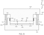
- Fig. 3 schematically illustrates an example of the tool 102 in a closed state.
- the tool lid 108 is movable relative to the tool base 104 such that the tool 102 is in the open state ( Fig. 2 ) or the closed state ( Fig. 3 ).
- the dry preform 204 ( Fig. 3 ) is placed on the base surface 106.
- the tool lid 108 is placed over the tool base 104 to create the tool cavity 126, which is sealed (e.g., a sealed cavity), for example, by one or more seals 152.
- Fig. 4 schematically illustrates an example of the tool 102 in the closed state and the tool lid 108 in a first tool position 146 for resin injection.
- the tool cavity 126 defines a gap 112.
- the resin 202 is injected into the gap 112 of the tool cavity 126 and flows over and across the dry preform 204.
- the gap 112 corresponds to a cavity volume 180 that is at least approximately equivalent to an amount (e.g., a volume) of the resin 202 sufficient to infuse the dry preform 204.
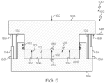
- Fig. 5 schematically illustrates an example of the tool 102 in the closed state and the tool lid 108 in a second tool position 148 for resin infusion and an initial portion of a curing process.
- the dry preform 204 is infused with the resin 202 within the tool cavity 126 to form the resin-infused preform 206.
- the tool lid 108 is lowered (e.g., from the first tool position 146 to the second tool position 148) to close the gap 112 such that the tool lid 108 applies an infusion pressure (e.g., the predetermined pressure 214) to help infuse the dry preform 204 with the resin 202 for a predetermined infusion time.
- the gap 112 corresponds to a desired thickness (e.g., thickness 208) of the resin-infused preform 206.
- the first tool position 146 and the second tool position 148 are the same, such that the gap 112 remains the same during injection of the resin 202 and infusion of the resin 202. In one or more examples, the first tool position 146 and the second tool position 148 are different, such that the gap 112 changes (e.g., is reduced) during injection of the resin 202 and infusion of the resin 202.
- the tool lid 108 with the tool lid 108 in the second tool position 148, curing of the resin-infused preform 206 commences.
- the tool lid 108 after infusion and with the tool lid 108 in the second tool position 148, the tool lid 108 also applies a curing pressure (e.g., the predetermined pressure 214) to the resin-infused preform 206 for a predetermined curing time.
- a curing pressure e.g., the predetermined pressure 214
- the tool lid 108 applies the predetermined pressure 214 across the resin-infused preform 206.
- Fig. 6 schematically illustrates an example of the of the tool 102 in the closed state and the tool lid 108 in a second tool position 148 during cure.
- the volume 210 of the resin-infused preform 206 decreases to some degree during cure.
- the gap 112 corresponds to a cavity volume 180 that is greater than the volume 210 of the resin-infused preform 206.
- the lid surface 110 of the tool lid 108 may no longer be in contact with a surface of the resin-infused preform 206 and/or the tool lid 108 may no longer be applying a sufficient force upon the resin-infused preform 206.
- Fig. 7 schematically illustrates an example of the tool 102 in the closed state and the tool lid 108 in a third tool position 150 during curing.
- the tool lid 108 is lowered (e.g., from the second tool position 148 to the third tool position 150) to close the gap 112 such that the tool lid 108 continues to apply the curing pressure, thereby maintaining the predetermined pressure 214 throughout the curing process as the volume 210 of the resin-infused preform 206 decreases.
- the gap 112 once again corresponds to a cavity volume 180 that is at least approximately equivalent to the volume 210 of the resin-infused preform 206.
- the tool lid 108 continues to apply the curing pressure (e.g., the predetermined pressure 214) to the resin-infused preform 206 for a remainder of the predetermined curing time.
- the tool lid 108 can be further lowered (e.g., from the third tool position 150 to a fourth tool position, from the fourth tool position to a fifth tool position, and so on, as needed) to close the gap 112 such that the tool lid 108 continues to apply the curing pressure, thereby maintaining the predetermined pressure 214 throughout the curing process as the volume 210 of the resin-infused preform 206 decreases.
- control of the tool position 144 e.g., from the first tool position 146 to the second tool position 148, from the second tool position 148 to the third tool position 150, and so on, as needed
- control of the adjustable stop 114 is provided by any one of various techniques, including an active control technique and a passive control technique.
- the adjustable stop 114 controls the tool position 144 of the tool lid 108 relative to the tool base 104 to selectively control a dimension 116 of the gap 112 between the base surface 106 and the lid surface 110.
- the dimension 116 of the gap 112 is a linear distance between the base surface 106 and the lid surface 110.
- the gap 112 corresponds to the cavity volume 180 of the tool cavity 126.
- the adjustable stop 114 sets the tool position 144 of the tool lid 108 relative to the tool base 104 to achieve a first predetermined value 172 for the dimension 116 of the gap 112 for injection and/or infusion of the resin 202.
- the first predetermined value 172 for the dimension 116 of the gap 112 corresponds to the first tool position 146 (e.g., Figs. 3 and 4 ).
- the adjustable stop 114 adjusts the position of the tool lid 108 relative to the tool base 104 to achieve a second predetermined value 174 for the dimension 116 of the gap 112 for infusion of the resin 202 and/or cure of the resin-infused preform 206.
- the second predetermined value 174 for the dimension 116 of the gap 112 corresponds to the thickness 208 of the resin-infused preform 206.
- the second predetermined value 174 for the dimension 116 of the gap 112 corresponds to the second tool position 148 (e.g., Figs. 5 and 6 ).
- the adjustable stop 114 adjusts the position of the tool lid 108 relative to the tool base 104 to achieve a third predetermined value 176 for the dimension 116 of the gap 112 for cure of the resin-infused preform 206 after some degree of volumetric decrease (e.g., shrinkage).
- the third predetermined value 176 for the dimension 116 of the gap 112 corresponds to the reduction in the volume 210 of the resin-infused preform 206 during cure.
- the third predetermined value 176 for the dimension 116 of the gap 112 corresponds to the third tool position 150 (e.g., Fig. 7 ).
- the system 100 includes a gap measurement sensor 132.
- the gap measurement sensor 132 measures the dimension 116 of the gap 112 between the base surface 106 and the lid surface 110.
- the gap measurement sensor 132 is positioned between the tool base 104 and the tool lid 108. With the tool 102 in the closed state, the gap measurement sensor 132 detects the tool position 144 and, thus, detects or determines the dimension 116 of the gap 112 between the base surface 106 and the lid surface 110 based on the tool position 144.
- the system 100 includes a plurality of gap measurement sensors 178.
- each one of the gap measurement sensors 178 measures the dimension 116 of the gap 112 between the base surface 106 and the lid surface 110, such as corresponding to one of the plurality of adjustable stops 140.
- the gap measurement sensor 132 may include or take the form of any suitable sensor, detector, or dimensional measurement tool or gauge that measures a gap or clearance.
- the gap measurement sensor 132 such as any one of the plurality of gap measurement sensors 178, may be a contact measurement device or a non-contact measurement device.
- the gap measurement sensor 132 such as any one of the plurality of gap measurement sensors 178, generates a dimension measurement 182.
- the adjustable stop 114 controls movement of the tool lid 108 relative to the tool base 104 to selectively control the interior pressure 134 within the tool cavity 126 and, thus, the predetermined pressure 214 across the resin-infused preform 206. In one or more examples, the adjustable stop 114 adjusts or controls the tool position 144 of the tool lid 108 relative to the tool base 104 to maintain the constant value 170 for the interior pressure 134 and, thus, the constant pressure 216 across the resin-infused preform 206.
- the tool position 144 is actively controlled using the adjustable stop 114 based on detection and/or monitoring of the dimension 116 of the gap 112 over time during cure and a model of the resin-infused preform 206.
- the model of the resin-infused preform 206 represents and correlates changes in the thickness 208 and/or volume 210 of the resin-infused preform 206 over time during cure, such as a look-up table, mathematical model, or computer model.
- the adjustable stop 114 automatically adjusts the tool position 144 (e.g., lowers the tool lid 108) to change (e.g., reduce) the dimension 116 of the gap 112 at predetermined times or at a predetermined rate over the predetermined curing time, according to the model, to maintain the constant value 170 for the interior pressure 134 and, thus, the constant pressure 216 across the resin-infused preform 206.
- a press force 160 is applied to the tool lid 108 to move the tool lid 108 relative to the tool base 104 (e.g., at different instances of the tool position 144).
- the tool lid 108 applied the press force 160 to the resin-infused preform 206 and the adjustable stop 114.
- the press force 160 is related to the interior pressure 134 of the tool cavity 126 and, thus, the pressure and/or force applied across the resin-infused preform 206.
- the resin-infused preform 206 applies a preform reaction force 162 to the tool lid 108 in response to the press force 160.
- the adjustable stop 114 applies a stop reaction force 158 to the tool lid 108 in response to the press force 160.
- a sum of the preform reaction force 162 and the stop reaction force 158 is desirable for a sum of the preform reaction force 162 and the stop reaction force 158 to be approximately equal to the press force 160, which results in the desired isostatic pressure being applied to the resin-infused preform 206 during the cure process. It can be appreciated that as the volume 210 of the resin-infused preform 206 decreases during cure, the preform reaction force 162 applied to the tool lid 108 by the resin-infused preform 206 decreases. This, in turn, causes an increase in the stop reaction force 158 applied to the tool lid 108 by the adjustable stop 114 needed to hold the tool lid 108 in the tool position 144.
- the stop reaction force 158 is sufficiently decreased to enable the tool lid 108 to be further lowered until the sum of the preform reaction force 162 and the stop reaction force 158 are again approximately equal to the press force 160.
- the tool position 144 is actively controlled using the adjustable stop 114 based on detection of, determination of, and/or changes in the interior pressure 134.
- the system 100 includes a pressure sensor 130.
- the pressure sensor 130 measures the interior pressure 134 within the tool cavity 126.
- one or more of the pressure sensors 184 measure the pressure or force applied across the resin-infused preform 206.
- the adjustable stop 114 automatically adjusts the tool position 144 (e.g., lowers the tool lid 108) in response to a detected change or reduction in the interior pressure 134 and, thus, a reduction in the pressure and/or force being applied across the resin-infused preform 206 to maintain the constant value 170 for the interior pressure 134 and, thus, the constant pressure 216 across the resin-infused preform 206.
- the system 100 includes a plurality of pressure sensors 184.
- one or more of the pressure sensors 184 measures the interior pressure 134 of the tool cavity 126.
- one or more of the pressure sensors 184 measure the pressure or force applied across the resin-infused preform 206.
- the pressure sensor 130 may include or take the form of any suitable sensor, detector, or pressure or force measurement tool or gauge that measures a pressurized gas, an applied force, or a reaction force.
- the pressure sensor 130 such as any one of the plurality of pressure sensors 184, may be a contact measurement device or a non-contact measurement device.
- the pressure sensor 130 such as any one of the plurality of pressure sensors 184, generates a pressure measurement 186.
- the pressure sensor 130 such as any one of the plurality of pressure sensors 184, is disposed on one or both of the base surface 106 and/or the lid surface 110.
- the pressure sensor 130, such as any one of the plurality of pressure sensors 184 is in communication (e.g., fluid communication) with the tool cavity 126.
- the tool position 144 is actively controlled using the adjustable stop 114 based on detection of, determination of, and/or changes in an internal pressure 164 within the adjustable stop 114 or the stop reaction force 158 applied by the adjustable stop 114.
- the system 100 includes a force sensor 188.
- the force sensor 188 measures the internal pressure 164 within the adjustable stop 114 or the stop reaction force 158 being applied by the adjustable stop 114.
- the adjustable stop 114 automatically adjusts the tool position 144 (e.g., lowers the tool lid 108) in response to a detected change (e.g., increase) in the internal pressure 164 within the adjustable stop 114 or the stop reaction force 158 being applied by the adjustable stop 114, which correspond to a reduction in the interior pressure 134 and, thus, a reduction in the pressure and/or force being applied across the resin-infused preform 206, to maintain the constant value 170 for the interior pressure 134 and, thus, the constant pressure 216 across the resin-infused preform 206.
- a detected change e.g., increase
- the system 100 includes a plurality of force sensors 190.
- each one of the force sensors 190 corresponds to and/or measures the internal pressure 164 within the adjustable stop 114 or the stop reaction force 158 being applied by the adjustable stop 114 of a corresponding one of the plurality of adjustable stops 140.
- the force sensor 188 may include or take the form of any suitable sensor, detector, or pressure or force measurement tool or gauge that measures an internal pressure of a cylinder, an applied load or force, or a reaction force.
- the force sensor 188 such as any one of the plurality of force sensors 190, may be a contact measurement device or a non-contact measurement device.
- the force sensor 188 such as any one of the plurality of force sensors 190, generates a force measurement 192.
- the force sensor 188 such as any one of the plurality of force sensors 190, is coupled to, is disposed in, or is in communication with a corresponding one of the plurality of adjustable stops 140.
- the tool position 144 is passively controlled using the adjustable stop 114 based on balancing of forces.
- the adjustable stop 114 reacts to the tool lid 108 to maintain the constant value 170 for the interior pressure 134 and, thus, the constant pressure 216 across the resin-infused preform 206.
- the stop reaction force 158 is set at a predetermined value to balance the forces between the press force 160 and the sum of the preform reaction force 162 and the stop reaction force 158.
- the press force 160 overcomes the stop reaction force 158, which in turn enables the tool lid 108 to lower until the sum of the sum of the preform reaction force 162 and the stop reaction force 158 is again at least approximately equal to the press force 160.
- the tool lid 108 is held at the tool position 144 by the adjustable stop 114 to maintain the constant value 170 for the interior pressure 134 and, thus, the constant pressure 216 across the resin-infused preform 206.
- the system 100 includes a controller 118.
- the controller 118 communicates with the adjustable stop 114 to instruct at least one of a stop position 120 of the adjustable stop 114 and the stop reaction force 158 applied by the adjustable stop 114.
- the system 100 include one or more sensors 128.
- the sensors 128 measure and generate measurements 154 representing at least one of the interior pressure 134 within the tool cavity 126, the dimension 116 of the gap 112 between the base surface 106 and the lid surface 110; the internal pressure 164 of the adjustable stop 114, and/or the stop reaction force 158 applied by the adjustable stop 114.
- the pressure sensor 130, the gap measurement sensor 132, and the force sensor 188 are examples of the sensors 128.
- the dimension measurement 182, the pressure measurement 186, and the force measurement 192 are examples of the measurements 154.
- the system 100 includes a feedback loop 166.
- the feedback loop 166 responds to changes in the interior pressure 134 within the tool cavity 126.
- the feedback loop 166 responds to changes in the internal pressure 164 of the adjustable stop 114 and/or the stop reaction force 158.
- the feedback loop 166 also provides changes in at least one of the stop position 120 of the adjustable stop 114 and the stop reaction force 158 that is applied by the adjustable stop 114 to adjust the tool position 144 of the tool lid 108 and to maintain the constant value 170 for the interior pressure 134 within the tool cavity 126 and the constant pressure 216 applied across the resin-infused preform 206.
- the controller 118 generates commands 156 and transmits the commands 156 to the adjustable stop 114 based on the measurements 154.
- the tool 102 and, more particularly, the tool base 104 and the tool lid 108 are configured for a desired shape, geometry, and contour of the composite structure 200 being formed.
- at least one of the base surface 106 and the lid surface 110 is planar (e.g., Figs. 2-7 ).
- at least one of an inner mold line or an outer mold line of the composite structure 200 is planar.
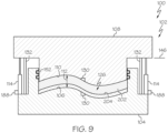
- at least one of the base surface 106 and the lid surface 110 is contoured (e.g., Fig. 9 ).
- at least one of the inner mold line or the outer mold line of the composite structure 200 is contoured.
- the system 100 includes the plurality of adjustable stops 140.
- the plurality of adjustable stops 140 is suitably dispersed between the tool base 104 and the tool lid 108.
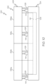
- the tool lid 108 includes a plurality of lid sections 138.
- the example illustrated in Fig. 10 depicts the tool lid 108 as having four lid sections 138, identified as first lid section 138a, second lid section 138b, third lid section 138c, and fourth lid section 138d.
- the tool lid 108 can have any number of lid sections 138.
- At least one of the plurality of adjustable stops 140 (identified individually as the adjustable stop 114 in Fig. 10 ) is positioned between the tool base 104 and each one of the plurality of lid sections 138.
- Each one of the lid sections 138 is associated with a portion or section of the resin-infused preform 206.
- each one of the lid sections 138 includes the tool position 144 associated with the associated section of the resin-infused preform 206, which is controlled by corresponding ones of the adjustable stops 140 to set the thickness 208 and to maintain the interior pressure 134 and the predetermined pressure 214 corresponding to that section of the resin-infused preform 206.
- the adjustable stop 114 can include any suitable device or mechanism capable of reacting to the tool lid 108 and/or controlling the tool position 144 of the tool lid 108 during resin injection, resin infusion, and resin cure.
- the adjustable stop 114 includes or takes the form of a linear actuator 124.
- the linear actuator 124 include hydraulic actuators (e.g., hydraulic cylinders), pneumatic actuators (e.g., pneumatic cylinders), and mechanical actuators (e.g., drive screws, motors, linear sliders, and the like).
- the adjustable stop 114 includes or takes the form of a spring 136.
- the adjustable stop 114 includes or takes the form of an inflatable bladder 196 (e.g., internally pressurized bladder). It can be appreciated that the type or function of the force sensor 188 and the type of the force measurement 192 generated by the force sensor 188 depends on the type of the adjustable stop 114.
- the present disclosure is also directed to the tool 102 for infusing the resin 202 in the dry preform 204.
- the tool 102 is used with or forms a portion of the system 100.
- the tool 102 provides control for maintaining a predetermined pressure or force on a resin-infused fiber-reinforced composite part during cure.
- the tool 102 includes the tool base 104 that includes the base surface 106.
- the tool 102 includes the tool lid 108 that includes the lid surface 110.
- the tool 102 includes the adjustable stop 114 that is positioned between the tool base 104 and the tool lid 108.
- the base surface 106 and the lid surface 110 form a portion of the tool cavity 126.
- the dry preform 204 is infused with the resin 202 within the tool cavity 126 to form the resin-infused preform 206.
- the tool lid 108 is movable relative to the tool base 104 to generate the predetermined pressure 214 across the resin-infused preform 206 (e.g., characterized by the interior pressure 134 within the tool cavity 126).
- the adjustable stop 114 controls the tool position 144 of the tool lid 108 relative to the tool base 104 to maintain the predetermined pressure 214.
- the adjustable stop 114 controls movement of the tool lid 108 relative to the tool base 104 to selectively control at least one of the dimension 116 of the gap 112 between the base surface 106 and the lid surface 110 and/or the interior pressure 134 within the tool cavity 126.
- the tool 102 includes the sensors 128 that measures at least one of the interior pressure 134 within the tool cavity 126, the dimension 116 of the gap 112 between the base surface 106 and the lid surface 110, the internal pressure 164 of the adjustable stop 114, and/or the stop reaction force 158.
- the tool 102 includes the feedback loop 166 that responds to changes in the interior pressure 134 within the tool cavity 126 and/or that provides changes in at least one of the stop position 120 of the adjustable stop 114 and the stop reaction force 158 applied by the adjustable stop 114 to maintain a constant value for the interior pressure 134 within the tool cavity 126.
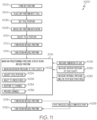
- the present disclosure is directed to a method 1000 for forming the composite structure 200.
- Examples of the method 1000 are implemented using the system 100 and/or the tool 102.
- the method 1000 facilitates tool control for maintaining a constant pressure or force on a resin-infused fiber-reinforced composite part during a cure process.
- the method 1000 includes a step of (block 1002) forming the dry preform 204 and a step of (block 1004) placing the dry preform 204 in the tool 102.
- the method 1000 includes a step of (block 1006) setting the tool position 144 of the tool lid 108 of the tool 102 relative to the tool base 104 of the tool 102.
- the tool position 144 is set to facilitate injection of the resin 202 within the tool cavity 126 such that the resin 202 fills the gap 112 and flows over the dry preform 204.
- the tool position 144 is set such that the gap 112 corresponds to the thickness 208 desired for the resin-infused preform 206.
- the tool position 144 is set to achieve the first predetermined value 172 for the dimension 116 of the gap 112 between the base surface 106 of the tool base 104 and the lid surface 110 of the tool lid 108 for injection of the resin 202. In one or more examples, the tool position 144 is set before infusing the resin 202. In one or more examples, the first predetermined value 172 for the dimension 116 of the gap 112 is selected to sufficiently enable the resin 202 to flow into the tool cavity 126 and across an entirety of a surface of the dry preform 204.
- the method 1000 includes a step of (block 1008) infusing the dry preform 204 positioned within the tool cavity 126 of the tool 102 with the resin 202 to form the resin-infused preform 206.
- the method 1000 includes a step of (block 1010) adjusting the tool position 144 of the tool lid 108 relative to the tool base 104, as needed, for infusion of the resin 202 and/or cure of the resin-infused preform 206.
- the tool position 144 is adjusted to achieve the second predetermined value 174 for the dimension 116 of the gap 112 that corresponds to the thickness 208 of the resin-infused preform 206.
- the tool position 144 is adjusted before infusing the resin.
- the tool position 144 is adjusted after infusing the resin 202.
- the second predetermined value for the dimension 116 of the gap 112 is selected to correspond to a desired value for the thickness 208 of the resin-infused preform 206 after the resin 202 flows into the tool cavity 126 and across the entirety of the surface of the dry preform 204.
- the second predetermined value 174 for the dimension 116 of the gap 112 is approximately the same as the first predetermined value 172 for the dimension 116 of the gap 112.
- the method 1000 includes a step of (block 1012) forming the resin-infused preform 206 within the tool cavity 126.
- the method 1000 includes a step of (block 1014) curing the resin-infused preform 206 within the tool cavity 126.
- the method 1000 includes a step of (block 1016) maintaining a predetermined pressure 214 across the resin-infused preform 206 during the step of (block 1014) curing.
- the method 1000 includes a step of (block 1018) forming the cured composite part 212 within the tool cavity 126.
- the method 1000 includes a step of (block 1020) removing the cured composite part 212 from the tool 102.
- the resin-infused preform 206 is cured at the predetermined pressure 214.
- the predetermined pressure 214 is the constant pressure 216.
- the value for the pressure applied across the resin-infused preform 206 during curing is constant.
- the step of (block 1016) maintaining the predetermined pressure 214 includes a step of (block 1022) maintaining the interior pressure 134 within the tool cavity 126 at a predetermined value 168, such as the constant value 170, in response to a decrease in the volume 210 (e.g., shrinkage) of the resin-infused preform 206 during the step of (block 1014) curing.
- the step of (block 1016) maintaining the predetermined pressure 214 includes a step of (block 1024) adjusting the tool position 144, such as by reducing the dimension 116 of the gap 112 and lowering the tool lid 108, in response to a decrease in the volume 210 (e.g., shrinkage) of the resin-infused preform 206 during the step of (block 1014) curing.
- the step of (block 1016) maintaining the predetermined pressure 214 includes a step of (block 1026) reacting to the press force 160 of the tool lid 108, in response to a decrease in the volume 210 (e.g., shrinkage) of the resin-infused preform 206 during the step of (block 1014) curing.
- the resin-infused preform 206 is cured at a predetermined, such as a constant, curing temperature.
- the curing temperature can be set according to the resin 202. For example, some aerospace epoxy resins cure initially at 130°C, but fully cure at a temperature of about 170°C to 190°C. Accordingly, in one or more examples, the curing temperature can be set at a temperature from approximately 100°C to about 200°C.
- the resin-infused preform 206 is cured for a predetermined curing time.
- the curing time can be set to maximize production rate of the.
- the curing time can be set to cure the resin-infused preform 206 to a point where it can be removed from the tool 102 without damaging the resin-infused preform 206.
- the curing time can be set to fully cure the resin-infused preform 206 in the tool 102.
- the method 1000 includes a step of (block 1028) measuring the dimension 116 of the gap 112 between the base surface 106 and the lid surface 110.
- measurements of the dimension 116 of the gap 112 are used to control (e.g., set and/or adjust) the tool position 144 of the tool lid 108 relative to the tool base 104.
- a change in the tool position 144 can be based on the measurements of the dimension 116, which is correlated to a predetermined rate of volumetric decrease over time based on the type and/or composition of the resin 202 and/or the cure parameters (e.g., pressure, temperature, time) of the curing process.
- the step of (block 1016) maintaining the predetermined pressure 214 across the resin-infused preform 206 during cure is performed passively.
- the method 1000 such as the step of (block 1016) maintaining the predetermined pressure, includes the step of (block 1026) reacting to the press force 160 applied by the tool lid 108 in response to the decrease in the preform reaction force 162 applied by the resin-infused preform 206 to maintain the predetermined pressure (214), such as the predetermined value for the interior pressure 134 of the tool cavity 126.
- the step of (block 1026) reacting is performed by the adjustable stop 114 and can be considered a passive technique for maintaining the predetermined pressure and/or for balancing forces.
- the press force 160 applied by the tool lid 108 overcomes the stop reaction force 158 applied by the adjustable stop 114.
- the tool position 144 is adjusted (e.g., the tool lid 108 is moved further toward the tool base 104) until the lid surface 110 contacts the preform surface of the resin-infused preform 206 until the sum of the preform reaction force 162 and the stop reaction force 158 equal the press force 160.
- stop reaction force 158 applied by the adjustable stop 114 prevents the tool lid 108 from moving further or applying a greater pressure on the resin-infused preform 206.
- the step of (block 1016) maintaining the predetermined pressure 214 across the resin-infused preform 206 during cure is performed actively, such as in response to measurements 154 and under command from the controller 118.
- the method 1000 such as the step of (block 1016) maintaining the predetermined pressure 214, includes the step of (block 1024) adjusting the tool position 144 of the tool lid 108 of the tool 102 relative to the tool base 104 of the tool 102 to maintain the predetermined value, such as the constant value, for the interior pressure 134 and, thereby, the predetermined pressure 214 across the resin-infused preform 206, during the step of (block 1014) curing the resin-infused preform 206.
- the step of (block 1024) adjusting the tool position 144 is performed by the adjustable stop 114 and can be considered an active technique for maintaining the predetermined pressure 214 and/or for balancing forces.
- the method 1000 includes a step of (block 1030) measuring the interior pressure 134 within the tool cavity 126. Measurements of the interior pressure 134 of the tool cavity 126 are used to control (e.g., selectively adjust) the tool position 144 of the tool lid 108 relative to the tool base 104.
- a change in the tool position 144 is based on the measurements of the interior pressure 134 of the tool cavity 126 to maintain the predetermined pressure 214, to balance forces, and/or to accommodate for the decrease in the volume 210 (e.g., shrinkage) of the resin-infused preform 206 during cure.
- measurements of the dimension 116 of the gap 112 are used to control (e.g., selectively adjust) the tool position 144 of the tool lid 108 relative to the tool base 104.
- a change in the tool position 144 e.g.,, from the second predetermined value 174 for the dimension 116 of the gap 112 to the third predetermined value 176 for the dimension 116 of the gap 112 is based on the measurements of the dimension 116 of the gap 112 and predictions of volumetric decreases over time of the resin-infused preform 206 to maintain the predetermined pressure 214, to balance forces, and/or to accommodate for the decrease in the volume 210 (e.g., shrinkage) of the resin-infused preform 206 during cure.
- the method 1000 includes a step of (block 1032) measuring at least one of the internal pressure 164 of the adjustable stop 114 and/or the stop reaction force 158 applied to the tool lid 108 by the adjustable stop 114. Measurements of the internal pressure 164 and/or the stop reaction force 158 are used to control (e.g., selectively adjust) the tool position 144 of the tool lid 108 relative to the tool base 104.
- a change in the tool position 144 is based on the measurements of stop reaction force 158 to maintain the predetermined pressure 214, to balance forces, and/or to accommodate for the decrease in the volume 210 (e.g., shrinkage) of the resin-infused preform 206 during cure.
- the step of (block 1016) maintaining the predetermined pressure 214 across the resin-infused preform 206 during cure is performed using the feedback loop 166.
- the method 1000 includes a step of (block 1034) responding to changes in the interior pressure 134 within the tool cavity 126.
- the method 1000 also includes a step of (block 1036) providing changes in at least one of the stop position 120 of the adjustable stop 114, positioned between the tool base 104 of the tool 102 and the tool lid 108 of the tool 102, and the stop reaction force 158 applied by the adjustable stop 114 to maintain the predetermined pressure 214 across the resin-infused preform 206 (e.g., predetermined or constant value for the interior pressure 134 within the tool cavity 126).
- the method 1000 can also include a step of (block 1038) post-processing the cured composite part 212.
- An example of post-processing includes additional curing of the cured composite part 212 at a temperature higher than the curing temperature.
- the method 1000 includes a step of transferring the cured composite part 212 to a post-cure fixture.
- the controller 118 is adapted or configured to execute instructions and to provide operational commands to components of the system 100, such as to the adjustable stops 140.
- the adjustable stop 114 is activated and operates under direction of the controller 118.
- the controller 118 is programmed with instructions (e.g., in the form of program code) that, when executed by the controller 118, causes the controller 118 to perform operations.
- the controller 118 includes or takes the form of a computing device (e.g., one or more computers).
- the method 1000 is at least partially a computer-implemented method.
- the controller 118 includes or takes the form of a data processing system.
- the data processing system of the controller 118 includes a communications framework, which provides communications between a processor 122 and memory 198 (e.g., one or more storage devices).
- the processor 122 serves to execute instructions for software that can be loaded into the memory 198.
- the processor 122 is a number of processor units, a multi-processor core, or some other type of processor, depending on the particular implementation.
- the memory 198 is an example of a storage device or any piece of hardware that is capable of storing information, such as, for example, without limitation, at least one of data, program code in functional form, or other suitable information either on a temporary basis, a permanent basis, or both on a temporary basis and a permanent basis.
- the memory 198 may also be referred to as computer readable storage devices in one or more examples.
- the memory 198 is, for example, a random-access memory or any other suitable volatile or non-volatile storage device. Instructions for at least one of the operating system, applications, or programs can be located in the memory 198, which is in communication with the processor 122.
- the processes of the various examples and operations described herein can be performed by the processor 122 using computer-implemented instructions, which can be located in a memory, such as the memory 198.
- the instructions are also referred to as program code, computer usable program code, or computer readable program code that can be read and executed by the processor 122.
- the program code in the different examples can be embodied on different physical or computer readable storage media, such as the memory 198.
- the program code is located in a functional form on computer readable media that is selectively removable and can be loaded onto or transferred to the data processing system for execution by the processor.
- the program code and computer readable media form a computer program product.
- modules include hardware, software or a combination of hardware and software.
- a module can include one or more circuits configured to perform or execute the described functions or operations of the executed processes described herein.
- a module includes a processor, a storage device (e.g., a memory), and computer-readable storage medium having instructions that, when executed by the processor causes the processor to perform or execute the described functions and operations.
- a module takes the form of program code and computer readable media, together forming a computer program product.
- the system 100 is implemented using software, hardware, firmware, or a combination thereof.
- the operations performed by the system 100 are implemented using, for example, without limitation, the program code that is configured to run on the processor 122.
- firmware the operations performed by the system 100 may be implemented using, for example, without limitation, the program code and data stored in the memory 198 to run on the processor 122.
- the hardware may include one or more circuits that operate to perform the operations performed by the system 100.
- the hardware may take the form of a circuit system, an integrated circuit, an application specific integrated circuit (ASIC), a programmable logic device, or some other suitable type of hardware device configured to perform any number of operations.
- ASIC application specific integrated circuit
- a programmable logic device may be configured to perform certain operations.
- the device may be permanently configured to perform these operations or may be reconfigurable.
- a programmable logic device may take the form of, for example, without limitation, a programmable logic array, a programmable array logic, a field programmable logic array, a field programmable gate array, or some other type of programmable hardware device.
- the composite structure 200 includes any suitable composite part, article, object, component, and the liked, such as an aerospace composite structure used to form a fuselage, wings, and other components of an aircraft.
- the composite structure 200 includes or refers to the cured composite part 212.
- the cured composite part 212 is formed by infusing the dry preform 204 with the resin 202 to form the resin-infused preform 206 and then curing the resin-infused preform 206.
- the dry preform 204 includes any suitable fiber reinforcement material. In one or more examples, the dry preform 204 is formed from raw fiber material that is cut into a desired pattern.
- plies of raw material are cut into flat patterns and the flat patterns are formed into the dry preform 204.
- the dry preform 204 can include from 1 to 8 plies of a fibrous material with any suitable per-ply areal weight.
- the raw material can include carbon fiber, glass fiber, aramid fiber, and the like or combinations thereof with a knit thread, with a knit thread and a thermoplastic veil, or fiber with a veil.
- the dry preform 204 includes carbon-fiber-based fabrics, such as non-crimp fabrics (NCFs).
- the resin 202 includes any suitable matrix material, such as an epoxy resin.
- the resin 202 can have a period of latency.
- the resin 202 includes epoxies, cyanate esters, benzoxazines, bismaleimides, polyimides, cross-linkable thermoplastics, and in situ polymerizable thermoplastics, or combination thereof.
- the resin 202 can include, without limitation, epoxy/cyanate esters and epoxy/benzoxazines.
- the term "cured” refers to a sufficient degree of stiffness and strength in the composite part, such that the composite part can be safely removed from a mold tool.
- the cured composite part 212 refers to a composite part that is sufficiently cured to maintain its shape without any distortion or damage after removal from the tool.
- additional curing, or post-curing can be performed to further develop additional stiffness and strength within the composite part to meet desired targets.
- examples of the system 100, the tool 102, and the method 1000 described herein may be related to, or used in the context of, an aircraft manufacturing and service method 1100, as shown in the flow diagram of Fig. 12 and an aircraft 1200, as schematically illustrated in Fig. 13 .
- the aircraft 1200 and/or the aircraft production and service method 1100 may include the composite structure 200 that is formed using the system 100 and/or the tool 102 and/or according to the method 1000.
- the aircraft 1200 includes an airframe 1202 having an interior 1206.
- the aircraft 1200 includes a plurality of onboard systems 1204 (e.g., high-level systems).
- Examples of the onboard systems 1204 of the aircraft 1200 include propulsion systems 1208, hydraulic systems 1212, electrical systems 1210, and environmental systems 1214.
- the onboard systems 1204 also includes one or more control systems coupled to an airframe 1202 of the aircraft 1200, such as for example, flaps, spoilers, ailerons, slats, rudders, elevators, and trim tabs.
- the onboard systems 1204 also includes one or more other systems, such as, but not limited to, communications systems, avionics systems, software distribution systems, network communications systems, passenger information/entertainment systems, guidance systems, radar systems, weapons systems, and the like.
- the aircraft 1200 may include various other composite structures made using the system 100 and/or the tool 102 and/or according to the method 1000.
- the manufacturing and service method 1100 includes specification and design of the aircraft 1200 (block 1102) and material procurement (block 1104).
- component and subassembly manufacturing (block 1106) and system integration (block 1108) of the aircraft 1200 take place. Thereafter, the aircraft 1200 goes through certification and delivery (block 1110) to be placed in service (block 1112).
- Routine maintenance and service (block 1114) includes modification, reconfiguration, refurbishment, etc. of one or more systems of the aircraft 1200.
- a system integrator may include, without limitation, any number of spacecraft manufacturers and major-system subcontractors; a third party may include, without limitation, any number of vendors, subcontractors, and suppliers; and an operator may be an airline, leasing company, military entity, service organization, and so on.
- Examples of the system 100, the tool 102, and the method 1000 shown and described herein, may be employed during any one or more of the stages of the manufacturing and service method 1100 shown in the flow diagram illustrated by Fig. 12 .
- forming the composite structure 200 using the system 100 and/or the tool 102 and/or according to the method 1000 may form a portion of component and subassembly manufacturing (block 1106) and/or system integration (block 1108).
- the composite structure 200 formed using the system 100 and/or the tool 102 and/or according to the method 1000 may be implemented in a manner similar to components or subassemblies prepared while the aircraft 1200 is in service (block 1112).
- the composite structure 200 formed using the system 100 and/or the tool 102 and/or according to the method 1000 may be utilized during system integration (block 1108) and certification and delivery (block 1110).
- the composite structure 200 formed using the system 100 and/or the tool 102 and/or according to the method 1000 may be utilized, for example and without limitation, while the aircraft 1200 is in service (block 1112) and during maintenance and service (block 1114).
- example means that one or more feature, structure, element, component, characteristic, and/or operational step described in connection with the example is included in at least one aspect, embodiment, and/or implementation of the subject matter according to the present disclosure.
- the phrases “an example,” “another example,” “one or more examples,” and similar language throughout the present disclosure may, but do not necessarily, refer to the same example.
- the subject matter characterizing any one example may, but does not necessarily, include the subject matter characterizing any other example.
- subject matter characterizing any one example may be, but is not necessarily, combined with the subject matter characterizing any other example.
- a system, apparatus, device, structure, article, element, component, or hardware "configured to” perform a specified function is indeed capable of performing the specified function without any alteration, rather than merely having potential to perform the specified function after further modification.
- the system, apparatus, device, structure, article, element, component, or hardware "configured to” perform a specified function is specifically selected, created, implemented, utilized, programmed, and/or designed for the purpose of performing the specified function.
- "configured to” denotes existing characteristics of a system, apparatus, structure, article, element, component, or hardware that enable the system, apparatus, structure, article, element, component, or hardware to perform the specified function without further modification.
- a system, apparatus, device, structure, article, element, component, or hardware described as being “configured to” perform a particular function may additionally or alternatively be described as being “adapted to” and/or as being “operative to” perform that function.
- first,” “second,” “third,” etc. are used herein merely as labels, and are not intended to impose ordinal, positional, or hierarchical requirements on the items to which these terms refer. Moreover, reference to, e.g., a “second” item does not require or preclude the existence of, e.g., a "first” or lower-numbered item, and/or, e.g., a "third” or higher-numbered item.
- the phrase "at least one of”, when used with a list of items, means different combinations of one or more of the listed items may be used and only one of each item in the list may be needed.
- “at least one of item A, item B, and item C” may include, without limitation, item A or item A and item B. This example also may include item A, item B, and item C, or item B and item C.
- "at least one of” may be, for example, without limitation, two of item A, one of item B, and ten of item C; four of item Band seven of item C; and other suitable combinations.
- the term “and/or” and the "j" symbol includes any and all combinations of one or more of the associated listed items.
- Coupled refers to two or more elements that are joined, linked, fastened, attached, connected, put in communication, or otherwise associated (e.g., mechanically, electrically, fluidly, optically, electromagnetically) with one another.
- the elements may be associated directly or indirectly.
- element A may be directly associated with element B.
- element A may be indirectly associated with element B, for example, via another element C. It will be understood that not all associations among the various disclosed elements are necessarily represented. Accordingly, couplings other than those depicted in the figures may also exist.
- the term “approximately” refers to or represent a condition that is close to, but not exactly, the stated condition that still performs the desired function or achieves the desired result.
- the term “approximately” refers to a condition that is within an acceptable predetermined tolerance or accuracy, such as to a condition that is within 10% of the stated condition.
- the term “approximately” does not exclude a condition that is exactly the stated condition.
- the term “substantially” refers to a condition that is essentially the stated condition that performs the desired function or achieves the desired result.
- Figs. 1A , 1B , 2-10 and 13 may represent functional elements, features, or components thereof and do not necessarily imply any particular structure. Accordingly, modifications, additions and/or omissions may be made to the illustrated structure. Additionally, those skilled in the art will appreciate that not all elements, features, and/or components described and illustrated in Figs. 1A , 1B , 2-10 and 13 , referred to above, need be included in every example and not all elements, features, and/or components described herein are necessarily depicted in each illustrative example. Accordingly, some of the elements, features, and/or components described and illustrated in Figs.
- Figs. 11 and 12 referred to above, the blocks may represent operations, steps, and/or portions thereof and lines connecting the various blocks do not imply any particular order or dependency of the operations or portions thereof. It will be understood that not all dependencies among the various disclosed operations are necessarily represented. Figs. 11 and 12 and the accompanying disclosure describing the operations of the disclosed methods set forth herein should not be interpreted as necessarily determining a sequence in which the operations are to be performed. Rather, although one illustrative order is indicated, it is to be understood that the sequence of the operations may be modified when appropriate. Accordingly, modifications, additions and/or omissions may be made to the operations illustrated and certain operations may be performed in a different order or simultaneously. Additionally, those skilled in the art will appreciate that not all operations described need be performed.
- references throughout the present specification to features, advantages, or similar language used herein do not imply that all of the features and advantages that may be realized with the examples disclosed herein should be, or are in, any single example. Rather, language referring to the features and advantages is understood to mean that a specific feature, advantage, or characteristic described in connection with an example is included in at least one example. Thus, discussion of features, advantages, and similar language used throughout the present disclosure may, but do not necessarily, refer to the same example.
Landscapes
- Chemical & Material Sciences (AREA)
- Engineering & Computer Science (AREA)
- Mechanical Engineering (AREA)
- Composite Materials (AREA)
- Analytical Chemistry (AREA)
- Physics & Mathematics (AREA)
- General Physics & Mathematics (AREA)
- Casting Or Compression Moulding Of Plastics Or The Like (AREA)
Abstract
Description
- The present disclosure relates generally to composite manufacturing and, more particularly, to systems and methods for forming composite structures using high-rate resin infusion.
- Composite materials and structures, including resin-infused fiber-reinforced laminates, are commonly used in applications requiring high strength and light weight. Conventional systems and methods for forming composite structures are often time- and labor-intensive. Further, systems and methods for producing high-quality composite structures at high rates require precisely machined tooling and utilize processing equipment with hard stops to control cure pressure and part thickness. However, fabricating high-quality composite structures that meet desired performance characteristics at high rates using current production systems and methods is difficult and expensive. Accordingly, those skilled in the art continue with research and development efforts in the field of composite manufacturing.
- Disclosed are examples of a system for forming a composite structure as defined in
claim 1, a tool for forming a composite structure as defined in claim 13, and a method for forming a composite structure as defined in claim 14. Further examples are defined in the dependent claims. The following is a non-exhaustive list of examples, which may or may not be claimed, of the subject matter according to the present disclosure. - In an example, the disclosed system includes a tool for infusing a dry preform with a resin. The tool includes a tool base and a tool lid. The tool base includes a base surface. The tool lid includes a lid surface. The system includes an adjustable stop that is positioned between the tool base and the tool lid. The base surface and the lid surface form a portion of a tool cavity. The tool lid is movable relative to the tool base to generate an internal pressure within the tool cavity. The adjustable stop controls a tool position of the tool lid relative to the tool base to achieve a predetermined value for the internal pressure.
- In an example, the disclosed tool includes a tool base that includes a base surface. The tool includes a tool lid that includes a lid surface. The tool includes an adjustable stop that is positioned between the tool base and the tool lid. The base surface and the lid surface form a portion of a tool cavity. A dry preform is infused with a resin within the tool cavity to form a resin-infused preform. The tool lid is movable relative to the tool base to generate a predetermined pressure across the resin-infused preform. The adjustable stop controls a tool position of the tool lid relative to the tool base to maintain the predetermined pressure during cure of the resin-infused preform.
- In an example, the disclosed method includes steps of: (1) infusing a dry preform with a resin to form a resin-infused preform within a tool cavity of a tool; and (2) maintaining a predetermined pressure across the resin-infused preform during cure.
- Other examples of the system, the tool, and the method disclosed herein will become apparent from the following detailed description, the accompanying drawings, and the appended claims.
-
-
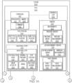
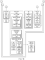
Figs. 1A and1B , in combination, are a schematic, block diagram of an example of system for forming a composite structure; -
Fig. 2 is schematic, sectional, end view of an example of a tool for forming a composite structure depicted inFigs. 1A and1B , shown in an open state; -
Fig. 3 is a schematic, sectional, end view of an example of the tool depicted inFigs. 1A and1B , shown in a closed state; -
Fig. 4 is a schematic, sectional, end view of an example of the tool depicted inFigs. 1A and1B , shown in a first tool position; -
Fig. 5 is a schematic, sectional, end view of an example of the tool depicted inFigs. 1A and1B , shown in a second tool position; -
Fig. 6 is a schematic, sectional, end view of an example of the tool depicted inFigs. 1A and1B , shown in the second tool position; -
Fig. 7 is a schematic, sectional, end view of an example of the tool depicted inFigs. 1A and1B , shown in a third tool position; -
Fig. 8 is a schematic, block diagram of an example of a feedback loop of the system depicted inFigs. 1A and1B ; -
Fig. 9 is a schematic, sectional, end view of an example of the tool depicted inFigs. 1A and1B ; -
Fig. 10 is a schematic, side elevation view of an example of the tool depicted inFigs. 1A and1B ; -
Fig. 11 is a method flow diagram of an example of a method for forming a composite structure; -
Fig. 12 is a flow diagram of an example of an aircraft manufacturing and service method; and -
Fig. 13 is a schematic block diagram of an example of an aircraft. - Referring generally to
Figs. 1A ,1B and2-10 , by way of examples, the present disclosure is directed to asystem 100 for forming acomposite structure 200. As will be described in more detail herein, thesystem 100 provides tool control for maintaining a predetermined pressure or force on a resin-infused fiber-reinforced composite part during cure. Curing of the resin-infused part may also referred to herein as a cure process, a cure cycle, or a cure operation. - The present disclosure recognizes that a resin infusion process requires constant, isostatic pressure to be maintained across a resin-infused fiber-reinforced composite part for a predetermined curing time (e.g., approximately 30 minutes) while the resin cures. During the cure process, the resin transforms from a liquid state to a solid state by increased crosslinking in the polymer chains. This transformation can result in a small (e.g., approximately 1% to 2% or more) decrease in the volume of the resin during the cure process. This decrease in volume can result in a decrease in pressure across the resin-infused fiber-reinforced composite part during the cure process. This decrease in pressure can result in defects or other quality issues across the surface of the resin-infused fiber-reinforced composite part.
- The
system 100 provides a predetermined (e.g., constant) isostatic pressure to a resin-infused preform by balancing pressure and/or forces applied to the resin-infused preform and by controlling a position of tooling during infusion of a dry preform with resin and cure of the resin-infused preform. By balancing pressure and/or forces applied to the resin-infused preform and by controlling the position of a tooling, thesystem 100 accounts for a volumetric decrease, also referred to as shrinkage, of the resin-infused preform during cure to provide a high quality cured composite part. - Referring to
Figs. 1A and1B , in one or more examples, thesystem 100 includes atool 102 for infusing adry preform 204 with aresin 202 to form a resin-infusedpreform 206 and for curing the resin-infusedpreform 206 to form acomposite structure 200. Thetool 102 includes atool base 104 and atool lid 108. Thetool base 104 includes abase surface 106. Thetool lid 108 includes alid surface 110. Thesystem 100 also includes anadjustable stop 114. Theadjustable stop 114 is positioned or disposed between thetool base 104 and thetool lid 108. Thebase surface 106 and thelid surface 110 form a portion of atool cavity 126. Thedry preform 204 is infused with theresin 202 within thetool cavity 126 to form the resin-infusedpreform 206. Thetool lid 108 is movable relative to thetool base 104 to generate aninterior pressure 134 within thetool cavity 126 and, thus, to generate a predetermined pressure 214 across the resin-infusedpreform 206. Theadjustable stop 114 controls atool position 144 of thetool lid 108 relative to thetool base 104 to achieve and/or maintain apredetermined value 168 for theinterior pressure 134 and, thus, to maintain the predetermined pressure 214 during cure of the resin-infusedpreform 206. - In one or more examples, the
interior pressure 134 of thetool cavity 126 is, refers to, or corresponds to the predetermine pressure 214 across the resin-infusedpreform 206. In one or more examples, thepredetermined value 168 for theinterior pressure 134 of thetool cavity 126 is aconstant value 170. As such, in one or more examples, the predetermined pressure 214 applied and maintained across the resin-infusedpreform 206 during cure is aconstant pressure 216. - In one or more examples, the
system 100 includes a plurality of adjustable stops 140. In these examples, each one of the adjustable stops 140 is positioned or disposed between thetool base 104 and thetool lid 108. The adjustable stops 140, in combination or in coordination, control thetool position 144 of thetool lid 108 relative to thetool base 104 to achieve and/or maintain thepredetermined value 168 for theinterior pressure 134 and, thus, to maintain the predetermined pressure 214 during cure of the resin-infusedpreform 206. - Generally, the
tool 102 may also be referred to as a mold or a mold tool. Thetool base 104 may also be referred to as a first mold, a lower mold, or fixed (e.g., stationary) mold. Thetool lid 108 may also be referred to as a second mold, an upper mold, or movable mold. For the purpose of the present disclosure, theinterior pressure 134 of thetool cavity 126 includes, refers to, or otherwise corresponds to the pressure applied to or across the resin-infusedpreform 206 disposed within thetool cavity 126 during infusion of thedry preform 204 with theresin 202 and/or during cure of the resin-infusedpreform 206. -
Fig. 2 schematically illustrates an example of thetool 102 in an open state.Fig. 3 schematically illustrates an example of thetool 102 in a closed state. Generally, thetool lid 108 is movable relative to thetool base 104 such that thetool 102 is in the open state (Fig. 2 ) or the closed state (Fig. 3 ). In one or more example, with thetool 102 in the open state, the dry preform 204 (Fig. 3 ) is placed on thebase surface 106. In one or more examples, with thetool 102 in the closed state, thetool lid 108 is placed over thetool base 104 to create thetool cavity 126, which is sealed (e.g., a sealed cavity), for example, by one ormore seals 152. -
Fig. 4 schematically illustrates an example of thetool 102 in the closed state and thetool lid 108 in afirst tool position 146 for resin injection. With thetool 102 in the closed state, thetool cavity 126 defines agap 112. In one or more examples, with thetool lid 108 in thefirst tool position 146, theresin 202 is injected into thegap 112 of thetool cavity 126 and flows over and across thedry preform 204. In one or more examples, with thetool lid 108 in thefirst tool position 146, thegap 112 corresponds to acavity volume 180 that is at least approximately equivalent to an amount (e.g., a volume) of theresin 202 sufficient to infuse thedry preform 204. -
Fig. 5 schematically illustrates an example of thetool 102 in the closed state and thetool lid 108 in asecond tool position 148 for resin infusion and an initial portion of a curing process. In one or more examples, with thetool lid 108 in thesecond tool position 148, thedry preform 204 is infused with theresin 202 within thetool cavity 126 to form the resin-infusedpreform 206. In one or more examples, thetool lid 108 is lowered (e.g., from thefirst tool position 146 to the second tool position 148) to close thegap 112 such that thetool lid 108 applies an infusion pressure (e.g., the predetermined pressure 214) to help infuse thedry preform 204 with theresin 202 for a predetermined infusion time. In one or more examples, with thetool lid 108 in thesecond tool position 148, thegap 112 corresponds to a desired thickness (e.g., thickness 208) of the resin-infusedpreform 206. - In one or more examples, the
first tool position 146 and thesecond tool position 148 are the same, such that thegap 112 remains the same during injection of theresin 202 and infusion of theresin 202. In one or more examples, thefirst tool position 146 and thesecond tool position 148 are different, such that thegap 112 changes (e.g., is reduced) during injection of theresin 202 and infusion of theresin 202. - In one or more examples, with the
tool lid 108 in thesecond tool position 148, curing of the resin-infusedpreform 206 commences. In one or more examples, after infusion and with thetool lid 108 in thesecond tool position 148, thetool lid 108 also applies a curing pressure (e.g., the predetermined pressure 214) to the resin-infusedpreform 206 for a predetermined curing time. For example, with thetool lid 108 in thesecond tool position 148, thetool lid 108 applies the predetermined pressure 214 across the resin-infusedpreform 206. -
Fig. 6 schematically illustrates an example of the of thetool 102 in the closed state and thetool lid 108 in asecond tool position 148 during cure. In one or more examples, thevolume 210 of the resin-infusedpreform 206 decreases to some degree during cure. As such, during the curing process, with thetool lid 108 in thesecond tool position 148, thegap 112 corresponds to acavity volume 180 that is greater than thevolume 210 of the resin-infusedpreform 206. For example, as the resin-infusedpreform 206 shrinks, thelid surface 110 of thetool lid 108 may no longer be in contact with a surface of the resin-infusedpreform 206 and/or thetool lid 108 may no longer be applying a sufficient force upon the resin-infusedpreform 206. -
Fig. 7 schematically illustrates an example of thetool 102 in the closed state and thetool lid 108 in athird tool position 150 during curing. In one or more examples, thetool lid 108 is lowered (e.g., from thesecond tool position 148 to the third tool position 150) to close thegap 112 such that thetool lid 108 continues to apply the curing pressure, thereby maintaining the predetermined pressure 214 throughout the curing process as thevolume 210 of the resin-infusedpreform 206 decreases. In one or more examples, with thetool lid 108 in thethird tool position 150, thegap 112 once again corresponds to acavity volume 180 that is at least approximately equivalent to thevolume 210 of the resin-infusedpreform 206. - In one or more examples, the
tool lid 108 continues to apply the curing pressure (e.g., the predetermined pressure 214) to the resin-infusedpreform 206 for a remainder of the predetermined curing time. In one or more examples, thetool lid 108 can be further lowered (e.g., from thethird tool position 150 to a fourth tool position, from the fourth tool position to a fifth tool position, and so on, as needed) to close thegap 112 such that thetool lid 108 continues to apply the curing pressure, thereby maintaining the predetermined pressure 214 throughout the curing process as thevolume 210 of the resin-infusedpreform 206 decreases. - As will be described below, control of the tool position 144 (e.g., from the
first tool position 146 to thesecond tool position 148, from thesecond tool position 148 to thethird tool position 150, and so on, as needed) to achieve and maintain thepredetermined value 168 for theinterior pressure 134 of thetool cavity 126 and, thus, the predetermined pressure 214 across the resin-infusedpreform 206 is implemented using theadjustable stop 114. As will be described in more detail below, control of theadjustable stop 114 is provided by any one of various techniques, including an active control technique and a passive control technique. - Referring to
Figs. 1A and1B , in one or more examples, theadjustable stop 114 controls thetool position 144 of thetool lid 108 relative to thetool base 104 to selectively control adimension 116 of thegap 112 between thebase surface 106 and thelid surface 110. Thedimension 116 of thegap 112 is a linear distance between thebase surface 106 and thelid surface 110. Thegap 112 corresponds to thecavity volume 180 of thetool cavity 126. - In one or more examples, the
adjustable stop 114 sets thetool position 144 of thetool lid 108 relative to thetool base 104 to achieve a firstpredetermined value 172 for thedimension 116 of thegap 112 for injection and/or infusion of theresin 202. In one or more examples, the firstpredetermined value 172 for thedimension 116 of thegap 112 corresponds to the first tool position 146 (e.g.,Figs. 3 and4 ). - In one or more examples, the
adjustable stop 114 adjusts the position of thetool lid 108 relative to thetool base 104 to achieve a secondpredetermined value 174 for thedimension 116 of thegap 112 for infusion of theresin 202 and/or cure of the resin-infusedpreform 206. In one or more examples, the secondpredetermined value 174 for thedimension 116 of thegap 112 corresponds to thethickness 208 of the resin-infusedpreform 206. In one or more examples, the secondpredetermined value 174 for thedimension 116 of thegap 112 corresponds to the second tool position 148 (e.g.,Figs. 5 and6 ). - In one or more examples, the
adjustable stop 114 adjusts the position of thetool lid 108 relative to thetool base 104 to achieve a thirdpredetermined value 176 for thedimension 116 of thegap 112 for cure of the resin-infusedpreform 206 after some degree of volumetric decrease (e.g., shrinkage). In one or more examples, the thirdpredetermined value 176 for thedimension 116 of thegap 112 corresponds to the reduction in thevolume 210 of the resin-infusedpreform 206 during cure. In one or more examples, the thirdpredetermined value 176 for thedimension 116 of thegap 112 corresponds to the third tool position 150 (e.g.,Fig. 7 ). - In one or more examples, the
system 100 includes agap measurement sensor 132. Thegap measurement sensor 132 measures thedimension 116 of thegap 112 between thebase surface 106 and thelid surface 110. In one or more examples, thegap measurement sensor 132 is positioned between thetool base 104 and thetool lid 108. With thetool 102 in the closed state, thegap measurement sensor 132 detects thetool position 144 and, thus, detects or determines thedimension 116 of thegap 112 between thebase surface 106 and thelid surface 110 based on thetool position 144. - In one or more examples, the
system 100 includes a plurality ofgap measurement sensors 178. In one or more examples, each one of thegap measurement sensors 178 measures thedimension 116 of thegap 112 between thebase surface 106 and thelid surface 110, such as corresponding to one of the plurality of adjustable stops 140. - The
gap measurement sensor 132, such as any one of the plurality ofgap measurement sensors 178, may include or take the form of any suitable sensor, detector, or dimensional measurement tool or gauge that measures a gap or clearance. Thegap measurement sensor 132, such as any one of the plurality ofgap measurement sensors 178, may be a contact measurement device or a non-contact measurement device. Thegap measurement sensor 132, such as any one of the plurality ofgap measurement sensors 178, generates adimension measurement 182. - In one or more examples, the
adjustable stop 114 controls movement of thetool lid 108 relative to thetool base 104 to selectively control theinterior pressure 134 within thetool cavity 126 and, thus, the predetermined pressure 214 across the resin-infusedpreform 206. In one or more examples, theadjustable stop 114 adjusts or controls thetool position 144 of thetool lid 108 relative to thetool base 104 to maintain theconstant value 170 for theinterior pressure 134 and, thus, theconstant pressure 216 across the resin-infusedpreform 206. - In one or more examples, the
tool position 144 is actively controlled using theadjustable stop 114 based on detection and/or monitoring of thedimension 116 of thegap 112 over time during cure and a model of the resin-infusedpreform 206. The model of the resin-infusedpreform 206 represents and correlates changes in thethickness 208 and/orvolume 210 of the resin-infusedpreform 206 over time during cure, such as a look-up table, mathematical model, or computer model. In these examples, theadjustable stop 114 automatically adjusts the tool position 144 (e.g., lowers the tool lid 108) to change (e.g., reduce) thedimension 116 of thegap 112 at predetermined times or at a predetermined rate over the predetermined curing time, according to the model, to maintain theconstant value 170 for theinterior pressure 134 and, thus, theconstant pressure 216 across the resin-infusedpreform 206. - Generally, during infusion and cure, a
press force 160 is applied to thetool lid 108 to move thetool lid 108 relative to the tool base 104 (e.g., at different instances of the tool position 144). Thetool lid 108 applied thepress force 160 to the resin-infusedpreform 206 and theadjustable stop 114. Thepress force 160 is related to theinterior pressure 134 of thetool cavity 126 and, thus, the pressure and/or force applied across the resin-infusedpreform 206. The resin-infusedpreform 206 applies apreform reaction force 162 to thetool lid 108 in response to thepress force 160. Theadjustable stop 114 applies astop reaction force 158 to thetool lid 108 in response to thepress force 160. During infusion and cure, it is desirable for a sum of thepreform reaction force 162 and thestop reaction force 158 to be approximately equal to thepress force 160, which results in the desired isostatic pressure being applied to the resin-infusedpreform 206 during the cure process. It can be appreciated that as thevolume 210 of the resin-infusedpreform 206 decreases during cure, thepreform reaction force 162 applied to thetool lid 108 by the resin-infusedpreform 206 decreases. This, in turn, causes an increase in thestop reaction force 158 applied to thetool lid 108 by theadjustable stop 114 needed to hold thetool lid 108 in thetool position 144. To maintain theinterior pressure 134 of thetool cavity 126 at the predetermined value 168 (e.g., the constant value 170) and, thus, the predetermined pressure 214 (e.g., the constant pressure 216) across the resin-infusedpreform 206, thestop reaction force 158 is sufficiently decreased to enable thetool lid 108 to be further lowered until the sum of thepreform reaction force 162 and thestop reaction force 158 are again approximately equal to thepress force 160. - In one or more examples, the
tool position 144 is actively controlled using theadjustable stop 114 based on detection of, determination of, and/or changes in theinterior pressure 134. In one or more of these examples, thesystem 100 includes apressure sensor 130. In one or more examples, thepressure sensor 130 measures theinterior pressure 134 within thetool cavity 126. In one or more examples, one or more of thepressure sensors 184 measure the pressure or force applied across the resin-infusedpreform 206. In these examples, theadjustable stop 114 automatically adjusts the tool position 144 (e.g., lowers the tool lid 108) in response to a detected change or reduction in theinterior pressure 134 and, thus, a reduction in the pressure and/or force being applied across the resin-infusedpreform 206 to maintain theconstant value 170 for theinterior pressure 134 and, thus, theconstant pressure 216 across the resin-infusedpreform 206. - In one or more examples, the
system 100 includes a plurality ofpressure sensors 184. In one or more examples, one or more of thepressure sensors 184 measures theinterior pressure 134 of thetool cavity 126. In one or more examples, one or more of thepressure sensors 184 measure the pressure or force applied across the resin-infusedpreform 206. - The
pressure sensor 130, such as any one of the plurality ofpressure sensors 184, may include or take the form of any suitable sensor, detector, or pressure or force measurement tool or gauge that measures a pressurized gas, an applied force, or a reaction force. Thepressure sensor 130, such as any one of the plurality ofpressure sensors 184, may be a contact measurement device or a non-contact measurement device. Thepressure sensor 130, such as any one of the plurality ofpressure sensors 184, generates apressure measurement 186. In one or more examples, thepressure sensor 130, such as any one of the plurality ofpressure sensors 184, is disposed on one or both of thebase surface 106 and/or thelid surface 110. In one or more examples, thepressure sensor 130, such as any one of the plurality ofpressure sensors 184 is in communication (e.g., fluid communication) with thetool cavity 126. - In one or more examples, the
tool position 144 is actively controlled using theadjustable stop 114 based on detection of, determination of, and/or changes in aninternal pressure 164 within theadjustable stop 114 or thestop reaction force 158 applied by theadjustable stop 114. In one or more of these examples, thesystem 100 includes aforce sensor 188. In one or more examples, theforce sensor 188 measures theinternal pressure 164 within theadjustable stop 114 or thestop reaction force 158 being applied by theadjustable stop 114. In these examples, theadjustable stop 114 automatically adjusts the tool position 144 (e.g., lowers the tool lid 108) in response to a detected change (e.g., increase) in theinternal pressure 164 within theadjustable stop 114 or thestop reaction force 158 being applied by theadjustable stop 114, which correspond to a reduction in theinterior pressure 134 and, thus, a reduction in the pressure and/or force being applied across the resin-infusedpreform 206, to maintain theconstant value 170 for theinterior pressure 134 and, thus, theconstant pressure 216 across the resin-infusedpreform 206. - In one or more examples, the
system 100 includes a plurality offorce sensors 190. In one or more examples, each one of theforce sensors 190 corresponds to and/or measures theinternal pressure 164 within theadjustable stop 114 or thestop reaction force 158 being applied by theadjustable stop 114 of a corresponding one of the plurality of adjustable stops 140. - The
force sensor 188, such as any one of the plurality offorce sensors 190, may include or take the form of any suitable sensor, detector, or pressure or force measurement tool or gauge that measures an internal pressure of a cylinder, an applied load or force, or a reaction force. Theforce sensor 188, such as any one of the plurality offorce sensors 190, may be a contact measurement device or a non-contact measurement device. Theforce sensor 188, such as any one of the plurality offorce sensors 190, generates aforce measurement 192. In one or more examples, theforce sensor 188, such as any one of the plurality offorce sensors 190, is coupled to, is disposed in, or is in communication with a corresponding one of the plurality of adjustable stops 140. - In one or more examples, the
tool position 144 is passively controlled using theadjustable stop 114 based on balancing of forces. In one or more examples, theadjustable stop 114 reacts to thetool lid 108 to maintain theconstant value 170 for theinterior pressure 134 and, thus, theconstant pressure 216 across the resin-infusedpreform 206. In one or more of these examples, thestop reaction force 158 is set at a predetermined value to balance the forces between thepress force 160 and the sum of thepreform reaction force 162 and thestop reaction force 158. For example, when thepreform reaction force 162 decreases and, thus, theinterior pressure 134 of thetool cavity 126 and the pressure and/or force applied to the resin-infusedpreform 206 decreases, thepress force 160 overcomes thestop reaction force 158, which in turn enables thetool lid 108 to lower until the sum of the sum of thepreform reaction force 162 and thestop reaction force 158 is again at least approximately equal to thepress force 160. Upon a balance of the forces, thetool lid 108 is held at thetool position 144 by theadjustable stop 114 to maintain theconstant value 170 for theinterior pressure 134 and, thus, theconstant pressure 216 across the resin-infusedpreform 206. - Referring to
Figs. 1A and1B , in one or more examples, thesystem 100 includes acontroller 118. Thecontroller 118 communicates with theadjustable stop 114 to instruct at least one of astop position 120 of theadjustable stop 114 and thestop reaction force 158 applied by theadjustable stop 114. - Referring to
Figs. 1A ,1B and8 , in one or more examples, thesystem 100 include one ormore sensors 128. Thesensors 128 measure and generatemeasurements 154 representing at least one of theinterior pressure 134 within thetool cavity 126, thedimension 116 of thegap 112 between thebase surface 106 and thelid surface 110; theinternal pressure 164 of theadjustable stop 114, and/or thestop reaction force 158 applied by theadjustable stop 114. Thepressure sensor 130, thegap measurement sensor 132, and theforce sensor 188 are examples of thesensors 128. Thedimension measurement 182, thepressure measurement 186, and theforce measurement 192 are examples of themeasurements 154. - In one or more examples, the
system 100 includes afeedback loop 166. In one or more examples, thefeedback loop 166 responds to changes in theinterior pressure 134 within thetool cavity 126. In one or more examples, thefeedback loop 166 responds to changes in theinternal pressure 164 of theadjustable stop 114 and/or thestop reaction force 158. Thefeedback loop 166 also provides changes in at least one of thestop position 120 of theadjustable stop 114 and thestop reaction force 158 that is applied by theadjustable stop 114 to adjust thetool position 144 of thetool lid 108 and to maintain theconstant value 170 for theinterior pressure 134 within thetool cavity 126 and theconstant pressure 216 applied across the resin-infusedpreform 206. In one or more examples, thecontroller 118 generatescommands 156 and transmits thecommands 156 to theadjustable stop 114 based on themeasurements 154. - Referring to
Figs. 1A ,1B ,2-7 and9 , in one or more examples, thetool 102 and, more particularly, thetool base 104 and thetool lid 108 are configured for a desired shape, geometry, and contour of thecomposite structure 200 being formed. In one or more examples, at least one of thebase surface 106 and thelid surface 110 is planar (e.g.,Figs. 2-7 ). In these examples, at least one of an inner mold line or an outer mold line of thecomposite structure 200 is planar. In one or more examples, at least one of thebase surface 106 and thelid surface 110 is contoured (e.g.,Fig. 9 ). In these examples, at least one of the inner mold line or the outer mold line of thecomposite structure 200 is contoured. - Referring to
Figs. 1A ,1B ,2-7 ,9 and10 , in one or more examples, thesystem 100 includes the plurality of adjustable stops 140. As shown inFigs. 1A ,1B ,2-7 and9 , in one or more examples, the plurality of adjustable stops 140 is suitably dispersed between thetool base 104 and thetool lid 108. As illustrated inFig. 10 , in one or more examples, thetool lid 108 includes a plurality oflid sections 138. The example illustrated inFig. 10 depicts thetool lid 108 as having fourlid sections 138, identified asfirst lid section 138a,second lid section 138b,third lid section 138c, andfourth lid section 138d. However, thetool lid 108 can have any number oflid sections 138. At least one of the plurality of adjustable stops 140 (identified individually as theadjustable stop 114 inFig. 10 ) is positioned between thetool base 104 and each one of the plurality oflid sections 138. Each one of thelid sections 138 is associated with a portion or section of the resin-infusedpreform 206. Accordingly, each one of thelid sections 138 includes thetool position 144 associated with the associated section of the resin-infusedpreform 206, which is controlled by corresponding ones of the adjustable stops 140 to set thethickness 208 and to maintain theinterior pressure 134 and the predetermined pressure 214 corresponding to that section of the resin-infusedpreform 206. - Referring to
Figs. 1A and1B , theadjustable stop 114 can include any suitable device or mechanism capable of reacting to thetool lid 108 and/or controlling thetool position 144 of thetool lid 108 during resin injection, resin infusion, and resin cure. In one or more examples, theadjustable stop 114 includes or takes the form of alinear actuator 124. Examples of thelinear actuator 124 include hydraulic actuators (e.g., hydraulic cylinders), pneumatic actuators (e.g., pneumatic cylinders), and mechanical actuators (e.g., drive screws, motors, linear sliders, and the like). In one or more examples, theadjustable stop 114 includes or takes the form of aspring 136. In one or more examples, theadjustable stop 114 includes or takes the form of an inflatable bladder 196 (e.g., internally pressurized bladder). It can be appreciated that the type or function of theforce sensor 188 and the type of theforce measurement 192 generated by theforce sensor 188 depends on the type of theadjustable stop 114. - Referring generally to
Figs. 1A ,1B and2-10 , by way of examples, the present disclosure is also directed to thetool 102 for infusing theresin 202 in thedry preform 204. In one or more examples, thetool 102 is used with or forms a portion of thesystem 100. As described herein above, thetool 102 provides control for maintaining a predetermined pressure or force on a resin-infused fiber-reinforced composite part during cure. - Referring to
Figs. 1A and1B , in one or more examples, thetool 102 includes thetool base 104 that includes thebase surface 106. Thetool 102 includes thetool lid 108 that includes thelid surface 110. Thetool 102 includes theadjustable stop 114 that is positioned between thetool base 104 and thetool lid 108. Thebase surface 106 and thelid surface 110 form a portion of thetool cavity 126. Thedry preform 204 is infused with theresin 202 within thetool cavity 126 to form the resin-infusedpreform 206. Thetool lid 108 is movable relative to thetool base 104 to generate the predetermined pressure 214 across the resin-infused preform 206 (e.g., characterized by theinterior pressure 134 within the tool cavity 126). Theadjustable stop 114 controls thetool position 144 of thetool lid 108 relative to thetool base 104 to maintain the predetermined pressure 214. - In one or more examples, the
adjustable stop 114 controls movement of thetool lid 108 relative to thetool base 104 to selectively control at least one of thedimension 116 of thegap 112 between thebase surface 106 and thelid surface 110 and/or theinterior pressure 134 within thetool cavity 126. In one or more examples, thetool 102 includes thesensors 128 that measures at least one of theinterior pressure 134 within thetool cavity 126, thedimension 116 of thegap 112 between thebase surface 106 and thelid surface 110, theinternal pressure 164 of theadjustable stop 114, and/or thestop reaction force 158. In one or more examples, thetool 102 includes thefeedback loop 166 that responds to changes in theinterior pressure 134 within thetool cavity 126 and/or that provides changes in at least one of thestop position 120 of theadjustable stop 114 and thestop reaction force 158 applied by theadjustable stop 114 to maintain a constant value for theinterior pressure 134 within thetool cavity 126. - Referring generally to
Figs. 1A ,1B and2-10 and particularly toFig. 11 , by way of examples, the present disclosure is directed to amethod 1000 for forming thecomposite structure 200. Examples of themethod 1000 are implemented using thesystem 100 and/or thetool 102. As will be described in more detail herein, themethod 1000 facilitates tool control for maintaining a constant pressure or force on a resin-infused fiber-reinforced composite part during a cure process. - Referring to
Fig. 11 , in one or more examples, themethod 1000 includes a step of (block 1002) forming thedry preform 204 and a step of (block 1004) placing thedry preform 204 in thetool 102. In one or more examples, themethod 1000 includes a step of (block 1006) setting thetool position 144 of thetool lid 108 of thetool 102 relative to thetool base 104 of thetool 102. In one or more examples, thetool position 144 is set to facilitate injection of theresin 202 within thetool cavity 126 such that theresin 202 fills thegap 112 and flows over thedry preform 204. In one or more examples, thetool position 144 is set such that thegap 112 corresponds to thethickness 208 desired for the resin-infusedpreform 206. As an example, thetool position 144 is set to achieve the firstpredetermined value 172 for thedimension 116 of thegap 112 between thebase surface 106 of thetool base 104 and thelid surface 110 of thetool lid 108 for injection of theresin 202. In one or more examples, thetool position 144 is set before infusing theresin 202. In one or more examples, the firstpredetermined value 172 for thedimension 116 of thegap 112 is selected to sufficiently enable theresin 202 to flow into thetool cavity 126 and across an entirety of a surface of thedry preform 204. - In one or more examples, the
method 1000 includes a step of (block 1008) infusing thedry preform 204 positioned within thetool cavity 126 of thetool 102 with theresin 202 to form the resin-infusedpreform 206. In one or more examples, themethod 1000 includes a step of (block 1010) adjusting thetool position 144 of thetool lid 108 relative to thetool base 104, as needed, for infusion of theresin 202 and/or cure of the resin-infusedpreform 206. In one or more examples, thetool position 144 is adjusted to achieve the secondpredetermined value 174 for thedimension 116 of thegap 112 that corresponds to thethickness 208 of the resin-infusedpreform 206. In one or more examples, thetool position 144 is adjusted before infusing the resin. In one or more examples, thetool position 144 is adjusted after infusing theresin 202. As an example, the second predetermined value for thedimension 116 of thegap 112 is selected to correspond to a desired value for thethickness 208 of the resin-infusedpreform 206 after theresin 202 flows into thetool cavity 126 and across the entirety of the surface of thedry preform 204. In one or more examples, the secondpredetermined value 174 for thedimension 116 of thegap 112 is approximately the same as the firstpredetermined value 172 for thedimension 116 of thegap 112. - In one or more examples, the
method 1000 includes a step of (block 1012) forming the resin-infusedpreform 206 within thetool cavity 126. Themethod 1000 includes a step of (block 1014) curing the resin-infusedpreform 206 within thetool cavity 126. Themethod 1000 includes a step of (block 1016) maintaining a predetermined pressure 214 across the resin-infusedpreform 206 during the step of (block 1014) curing. Themethod 1000 includes a step of (block 1018) forming the curedcomposite part 212 within thetool cavity 126. Themethod 1000 includes a step of (block 1020) removing the curedcomposite part 212 from thetool 102. - The resin-infused
preform 206 is cured at the predetermined pressure 214. In one or more examples the predetermined pressure 214 is theconstant pressure 216. For example, the value for the pressure applied across the resin-infusedpreform 206 during curing is constant. In one or more examples, the step of (block 1016) maintaining the predetermined pressure 214 includes a step of (block 1022) maintaining theinterior pressure 134 within thetool cavity 126 at apredetermined value 168, such as theconstant value 170, in response to a decrease in the volume 210 (e.g., shrinkage) of the resin-infusedpreform 206 during the step of (block 1014) curing. In one or more examples, the step of (block 1016) maintaining the predetermined pressure 214 includes a step of (block 1024) adjusting thetool position 144, such as by reducing thedimension 116 of thegap 112 and lowering thetool lid 108, in response to a decrease in the volume 210 (e.g., shrinkage) of the resin-infusedpreform 206 during the step of (block 1014) curing. In one or more examples, the step of (block 1016) maintaining the predetermined pressure 214 includes a step of (block 1026) reacting to thepress force 160 of thetool lid 108, in response to a decrease in the volume 210 (e.g., shrinkage) of the resin-infusedpreform 206 during the step of (block 1014) curing. - In one or more examples, the resin-infused
preform 206 is cured at a predetermined, such as a constant, curing temperature. The curing temperature can be set according to theresin 202. For example, some aerospace epoxy resins cure initially at 130°C, but fully cure at a temperature of about 170°C to 190°C. Accordingly, in one or more examples, the curing temperature can be set at a temperature from approximately 100°C to about 200°C. - In one or more examples, the resin-infused
preform 206 is cured for a predetermined curing time. The curing time can be set to maximize production rate of the. For example, the curing time can be set to cure the resin-infusedpreform 206 to a point where it can be removed from thetool 102 without damaging the resin-infusedpreform 206. In other examples, the curing time can be set to fully cure the resin-infusedpreform 206 in thetool 102. - In one or more examples, the
method 1000 includes a step of (block 1028) measuring thedimension 116 of thegap 112 between thebase surface 106 and thelid surface 110. In one or more examples, measurements of thedimension 116 of thegap 112 are used to control (e.g., set and/or adjust) thetool position 144 of thetool lid 108 relative to thetool base 104. For example, as needed, a change in thetool position 144 can be based on the measurements of thedimension 116, which is correlated to a predetermined rate of volumetric decrease over time based on the type and/or composition of theresin 202 and/or the cure parameters (e.g., pressure, temperature, time) of the curing process. - In one or more examples, the step of (block 1016) maintaining the predetermined pressure 214 across the resin-infused
preform 206 during cure is performed passively. In one or more examples, themethod 1000, such as the step of (block 1016) maintaining the predetermined pressure, includes the step of (block 1026) reacting to thepress force 160 applied by thetool lid 108 in response to the decrease in thepreform reaction force 162 applied by the resin-infusedpreform 206 to maintain the predetermined pressure (214), such as the predetermined value for theinterior pressure 134 of thetool cavity 126. In these examples, the step of (block 1026) reacting is performed by theadjustable stop 114 and can be considered a passive technique for maintaining the predetermined pressure and/or for balancing forces. For example, when thepress force 160 becomes greater than the sum of thepreform reaction force 162 and thestop reaction force 158, thepress force 160 applied by thetool lid 108 overcomes thestop reaction force 158 applied by theadjustable stop 114. In turn, thetool position 144 is adjusted (e.g., thetool lid 108 is moved further toward the tool base 104) until thelid surface 110 contacts the preform surface of the resin-infusedpreform 206 until the sum of thepreform reaction force 162 and thestop reaction force 158 equal thepress force 160. At this equilibrium state, stopreaction force 158 applied by theadjustable stop 114 prevents thetool lid 108 from moving further or applying a greater pressure on the resin-infusedpreform 206. - In one or more examples, the step of (block 1016) maintaining the predetermined pressure 214 across the resin-infused
preform 206 during cure is performed actively, such as in response tomeasurements 154 and under command from thecontroller 118. In one or more examples, themethod 1000, such as the step of (block 1016) maintaining the predetermined pressure 214, includes the step of (block 1024) adjusting thetool position 144 of thetool lid 108 of thetool 102 relative to thetool base 104 of thetool 102 to maintain the predetermined value, such as the constant value, for theinterior pressure 134 and, thereby, the predetermined pressure 214 across the resin-infusedpreform 206, during the step of (block 1014) curing the resin-infusedpreform 206. In these examples, the step of (block 1024) adjusting thetool position 144 is performed by theadjustable stop 114 and can be considered an active technique for maintaining the predetermined pressure 214 and/or for balancing forces. - In one or more examples, the
method 1000 includes a step of (block 1030) measuring theinterior pressure 134 within thetool cavity 126. Measurements of theinterior pressure 134 of thetool cavity 126 are used to control (e.g., selectively adjust) thetool position 144 of thetool lid 108 relative to thetool base 104. For example, as needed, a change in the tool position 144 (e.g., from the secondpredetermined value 174 for thedimension 116 of thegap 112 to the thirdpredetermined value 176 for thedimension 116 of the gap 112) is based on the measurements of theinterior pressure 134 of thetool cavity 126 to maintain the predetermined pressure 214, to balance forces, and/or to accommodate for the decrease in the volume 210 (e.g., shrinkage) of the resin-infusedpreform 206 during cure. - In one or more examples, measurements of the
dimension 116 of thegap 112 are used to control (e.g., selectively adjust) thetool position 144 of thetool lid 108 relative to thetool base 104. For example, as needed, a change in the tool position 144 (e.g.,, from the secondpredetermined value 174 for thedimension 116 of thegap 112 to the thirdpredetermined value 176 for thedimension 116 of the gap 112) is based on the measurements of thedimension 116 of thegap 112 and predictions of volumetric decreases over time of the resin-infusedpreform 206 to maintain the predetermined pressure 214, to balance forces, and/or to accommodate for the decrease in the volume 210 (e.g., shrinkage) of the resin-infusedpreform 206 during cure. - In one or more examples, the
method 1000 includes a step of (block 1032) measuring at least one of theinternal pressure 164 of theadjustable stop 114 and/or thestop reaction force 158 applied to thetool lid 108 by theadjustable stop 114. Measurements of theinternal pressure 164 and/or thestop reaction force 158 are used to control (e.g., selectively adjust) thetool position 144 of thetool lid 108 relative to thetool base 104. For example, as needed, a change in the tool position 144 (e.g., from the secondpredetermined value 174 for thedimension 116 of thegap 112 to the thirdpredetermined value 176 for thedimension 116 of the gap 112) is based on the measurements ofstop reaction force 158 to maintain the predetermined pressure 214, to balance forces, and/or to accommodate for the decrease in the volume 210 (e.g., shrinkage) of the resin-infusedpreform 206 during cure. - In one or more examples, the step of (block 1016) maintaining the predetermined pressure 214 across the resin-infused
preform 206 during cure is performed using thefeedback loop 166. In one or more examples, themethod 1000 includes a step of (block 1034) responding to changes in theinterior pressure 134 within thetool cavity 126. Themethod 1000 also includes a step of (block 1036) providing changes in at least one of thestop position 120 of theadjustable stop 114, positioned between thetool base 104 of thetool 102 and thetool lid 108 of thetool 102, and thestop reaction force 158 applied by theadjustable stop 114 to maintain the predetermined pressure 214 across the resin-infused preform 206 (e.g., predetermined or constant value for theinterior pressure 134 within the tool cavity 126). - In one or more examples, the
method 1000 can also include a step of (block 1038) post-processing the curedcomposite part 212. An example of post-processing includes additional curing of the curedcomposite part 212 at a temperature higher than the curing temperature. In these examples, themethod 1000 includes a step of transferring the curedcomposite part 212 to a post-cure fixture. - Referring to
Figs. 1A and1B , in one or more examples, thecontroller 118 is adapted or configured to execute instructions and to provide operational commands to components of thesystem 100, such as to the adjustable stops 140. As an example, theadjustable stop 114 is activated and operates under direction of thecontroller 118. In one or more examples, thecontroller 118 is programmed with instructions (e.g., in the form of program code) that, when executed by thecontroller 118, causes thecontroller 118 to perform operations. In one or more examples, thecontroller 118 includes or takes the form of a computing device (e.g., one or more computers). In these examples, themethod 1000 is at least partially a computer-implemented method. - In one or more examples, the
controller 118 includes or takes the form of a data processing system. In one or more examples, the data processing system of thecontroller 118 includes a communications framework, which provides communications between aprocessor 122 and memory 198 (e.g., one or more storage devices). Theprocessor 122 serves to execute instructions for software that can be loaded into thememory 198. In one or more examples, theprocessor 122 is a number of processor units, a multi-processor core, or some other type of processor, depending on the particular implementation. Thememory 198 is an example of a storage device or any piece of hardware that is capable of storing information, such as, for example, without limitation, at least one of data, program code in functional form, or other suitable information either on a temporary basis, a permanent basis, or both on a temporary basis and a permanent basis. Thememory 198 may also be referred to as computer readable storage devices in one or more examples. Thememory 198 is, for example, a random-access memory or any other suitable volatile or non-volatile storage device. Instructions for at least one of the operating system, applications, or programs can be located in thememory 198, which is in communication with theprocessor 122. The processes of the various examples and operations described herein can be performed by theprocessor 122 using computer-implemented instructions, which can be located in a memory, such as thememory 198. The instructions are also referred to as program code, computer usable program code, or computer readable program code that can be read and executed by theprocessor 122. The program code in the different examples can be embodied on different physical or computer readable storage media, such as thememory 198. In one or more examples, the program code is located in a functional form on computer readable media that is selectively removable and can be loaded onto or transferred to the data processing system for execution by the processor. In one or more examples, the program code and computer readable media form a computer program product. Additionally, various components of thecontroller 118 and/or the data processing system may be described as modules. For the purpose of the present disclosure, the term "module" includes hardware, software or a combination of hardware and software. As an example, a module can include one or more circuits configured to perform or execute the described functions or operations of the executed processes described herein. As another example, a module includes a processor, a storage device (e.g., a memory), and computer-readable storage medium having instructions that, when executed by the processor causes the processor to perform or execute the described functions and operations. In one or more examples, a module takes the form of program code and computer readable media, together forming a computer program product. - In one or more examples, the
system 100 is implemented using software, hardware, firmware, or a combination thereof. When software is used, the operations performed by thesystem 100 are implemented using, for example, without limitation, the program code that is configured to run on theprocessor 122. When firmware is used, the operations performed by thesystem 100 may be implemented using, for example, without limitation, the program code and data stored in thememory 198 to run on theprocessor 122. When hardware is employed, the hardware may include one or more circuits that operate to perform the operations performed by thesystem 100. Depending on the implementation, the hardware may take the form of a circuit system, an integrated circuit, an application specific integrated circuit (ASIC), a programmable logic device, or some other suitable type of hardware device configured to perform any number of operations. A programmable logic device may be configured to perform certain operations. The device may be permanently configured to perform these operations or may be reconfigurable. A programmable logic device may take the form of, for example, without limitation, a programmable logic array, a programmable array logic, a field programmable logic array, a field programmable gate array, or some other type of programmable hardware device. - Referring to
Figs. 1A and1B , for the purpose of the present disclosure, thecomposite structure 200 includes any suitable composite part, article, object, component, and the liked, such as an aerospace composite structure used to form a fuselage, wings, and other components of an aircraft. Thecomposite structure 200 includes or refers to the curedcomposite part 212. The curedcomposite part 212 is formed by infusing thedry preform 204 with theresin 202 to form the resin-infusedpreform 206 and then curing the resin-infusedpreform 206. Thedry preform 204 includes any suitable fiber reinforcement material. In one or more examples, thedry preform 204 is formed from raw fiber material that is cut into a desired pattern. As an example, plies of raw material are cut into flat patterns and the flat patterns are formed into thedry preform 204. For example, thedry preform 204 can include from 1 to 8 plies of a fibrous material with any suitable per-ply areal weight. The raw material can include carbon fiber, glass fiber, aramid fiber, and the like or combinations thereof with a knit thread, with a knit thread and a thermoplastic veil, or fiber with a veil. As examples, thedry preform 204 includes carbon-fiber-based fabrics, such as non-crimp fabrics (NCFs). Theresin 202 includes any suitable matrix material, such as an epoxy resin. Theresin 202 can have a period of latency. In other examples, theresin 202 includes epoxies, cyanate esters, benzoxazines, bismaleimides, polyimides, cross-linkable thermoplastics, and in situ polymerizable thermoplastics, or combination thereof. For example, theresin 202 can include, without limitation, epoxy/cyanate esters and epoxy/benzoxazines. - For the purpose of the present disclosure, the term "cured" refers to a sufficient degree of stiffness and strength in the composite part, such that the composite part can be safely removed from a mold tool. As an example, the cured
composite part 212 refers to a composite part that is sufficiently cured to maintain its shape without any distortion or damage after removal from the tool. In some examples, after removal from the tool, additional curing, or post-curing, can be performed to further develop additional stiffness and strength within the composite part to meet desired targets. - Referring now to
Figs. 12 and 13 , examples of thesystem 100, thetool 102, and themethod 1000 described herein, may be related to, or used in the context of, an aircraft manufacturing andservice method 1100, as shown in the flow diagram ofFig. 12 and anaircraft 1200, as schematically illustrated inFig. 13 . For example, theaircraft 1200 and/or the aircraft production andservice method 1100 may include thecomposite structure 200 that is formed using thesystem 100 and/or thetool 102 and/or according to themethod 1000. - Referring to
Fig. 13 , which illustrates an example of theaircraft 1200. Theaircraft 1200 includes anairframe 1202 having an interior 1206. Theaircraft 1200 includes a plurality of onboard systems 1204 (e.g., high-level systems). Examples of theonboard systems 1204 of theaircraft 1200 includepropulsion systems 1208,hydraulic systems 1212,electrical systems 1210, andenvironmental systems 1214. In other examples, theonboard systems 1204 also includes one or more control systems coupled to anairframe 1202 of theaircraft 1200, such as for example, flaps, spoilers, ailerons, slats, rudders, elevators, and trim tabs. In yet other examples, theonboard systems 1204 also includes one or more other systems, such as, but not limited to, communications systems, avionics systems, software distribution systems, network communications systems, passenger information/entertainment systems, guidance systems, radar systems, weapons systems, and the like. Theaircraft 1200 may include various other composite structures made using thesystem 100 and/or thetool 102 and/or according to themethod 1000. - Referring to
Fig. 12 , during pre-production of theaircraft 1200, the manufacturing andservice method 1100 includes specification and design of the aircraft 1200 (block 1102) and material procurement (block 1104). During production of theaircraft 1200, component and subassembly manufacturing (block 1106) and system integration (block 1108) of theaircraft 1200 take place. Thereafter, theaircraft 1200 goes through certification and delivery (block 1110) to be placed in service (block 1112). Routine maintenance and service (block 1114) includes modification, reconfiguration, refurbishment, etc. of one or more systems of theaircraft 1200. - Each of the processes of the manufacturing and
service method 1100 illustrated inFig. 12 may be performed or carried out by a system integrator, a third party, and/or an operator (e.g., a customer). For the purposes of this description, a system integrator may include, without limitation, any number of spacecraft manufacturers and major-system subcontractors; a third party may include, without limitation, any number of vendors, subcontractors, and suppliers; and an operator may be an airline, leasing company, military entity, service organization, and so on. - Examples of the
system 100, thetool 102, and themethod 1000 shown and described herein, may be employed during any one or more of the stages of the manufacturing andservice method 1100 shown in the flow diagram illustrated byFig. 12 . In an example, forming thecomposite structure 200 using thesystem 100 and/or thetool 102 and/or according to themethod 1000 may form a portion of component and subassembly manufacturing (block 1106) and/or system integration (block 1108). Further, thecomposite structure 200 formed using thesystem 100 and/or thetool 102 and/or according to themethod 1000 may be implemented in a manner similar to components or subassemblies prepared while theaircraft 1200 is in service (block 1112). Also, thecomposite structure 200 formed using thesystem 100 and/or thetool 102 and/or according to themethod 1000 may be utilized during system integration (block 1108) and certification and delivery (block 1110). Similarly, thecomposite structure 200 formed using thesystem 100 and/or thetool 102 and/or according to themethod 1000 may be utilized, for example and without limitation, while theaircraft 1200 is in service (block 1112) and during maintenance and service (block 1114). - The preceding detailed description refers to the accompanying drawings, which illustrate specific examples described by the present disclosure. Other examples having different structures and operations do not depart from the scope of the present disclosure. Like reference numerals may refer to the same feature, element, or component in the different drawings. Throughout the present disclosure, any one of a plurality of items may be referred to individually as the item and a plurality of items may be referred to collectively as the items and may be referred to with like reference numerals. Moreover, as used herein, a feature, element, component, or step preceded with the word "a" or "an" should be understood as not excluding a plurality of features, elements, components, or steps, unless such exclusion is explicitly recited.
- Illustrative, non-exhaustive examples, which may be, but are not necessarily, claimed, of the subject matter according to the present disclosure are provided above. Reference herein to "example" means that one or more feature, structure, element, component, characteristic, and/or operational step described in connection with the example is included in at least one aspect, embodiment, and/or implementation of the subject matter according to the present disclosure. Thus, the phrases "an example," "another example," "one or more examples," and similar language throughout the present disclosure may, but do not necessarily, refer to the same example. Further, the subject matter characterizing any one example may, but does not necessarily, include the subject matter characterizing any other example. Moreover, the subject matter characterizing any one example may be, but is not necessarily, combined with the subject matter characterizing any other example.
- As used herein, a system, apparatus, device, structure, article, element, component, or hardware "configured to" perform a specified function is indeed capable of performing the specified function without any alteration, rather than merely having potential to perform the specified function after further modification. In other words, the system, apparatus, device, structure, article, element, component, or hardware "configured to" perform a specified function is specifically selected, created, implemented, utilized, programmed, and/or designed for the purpose of performing the specified function. As used herein, "configured to" denotes existing characteristics of a system, apparatus, structure, article, element, component, or hardware that enable the system, apparatus, structure, article, element, component, or hardware to perform the specified function without further modification. For purposes of this disclosure, a system, apparatus, device, structure, article, element, component, or hardware described as being "configured to" perform a particular function may additionally or alternatively be described as being "adapted to" and/or as being "operative to" perform that function.
- Unless otherwise indicated, the terms "first," "second," "third," etc. are used herein merely as labels, and are not intended to impose ordinal, positional, or hierarchical requirements on the items to which these terms refer. Moreover, reference to, e.g., a "second" item does not require or preclude the existence of, e.g., a "first" or lower-numbered item, and/or, e.g., a "third" or higher-numbered item.
- As used herein, the phrase "at least one of", when used with a list of items, means different combinations of one or more of the listed items may be used and only one of each item in the list may be needed. For example, "at least one of item A, item B, and item C" may include, without limitation, item A or item A and item B. This example also may include item A, item B, and item C, or item B and item C. In other examples, "at least one of" may be, for example, without limitation, two of item A, one of item B, and ten of item C; four of item Band seven of item C; and other suitable combinations. As used herein, the term "and/or" and the "j" symbol includes any and all combinations of one or more of the associated listed items.
- For the purpose of this disclosure, the terms "coupled," "coupling," and similar terms refer to two or more elements that are joined, linked, fastened, attached, connected, put in communication, or otherwise associated (e.g., mechanically, electrically, fluidly, optically, electromagnetically) with one another. In various examples, the elements may be associated directly or indirectly. As an example, element A may be directly associated with element B. As another example, element A may be indirectly associated with element B, for example, via another element C. It will be understood that not all associations among the various disclosed elements are necessarily represented. Accordingly, couplings other than those depicted in the figures may also exist.
- As used herein, the term "approximately" refers to or represent a condition that is close to, but not exactly, the stated condition that still performs the desired function or achieves the desired result. As an example, the term "approximately" refers to a condition that is within an acceptable predetermined tolerance or accuracy, such as to a condition that is within 10% of the stated condition. However, the term "approximately" does not exclude a condition that is exactly the stated condition. As used herein, the term "substantially" refers to a condition that is essentially the stated condition that performs the desired function or achieves the desired result.
- For the purpose of the present disclosure, the term "constant," for example, referring to a constant pressure, a constant value, and the like, refers to a value (e.g., a pressure value) having a variance of less than approximately 5% of the desired, stated value.
-
Figs. 1A ,1B ,2-10 and13 , referred to above, may represent functional elements, features, or components thereof and do not necessarily imply any particular structure. Accordingly, modifications, additions and/or omissions may be made to the illustrated structure. Additionally, those skilled in the art will appreciate that not all elements, features, and/or components described and illustrated inFigs. 1A ,1B ,2-10 and13 , referred to above, need be included in every example and not all elements, features, and/or components described herein are necessarily depicted in each illustrative example. Accordingly, some of the elements, features, and/or components described and illustrated inFigs. 1A ,1B ,2-10 and13 may be combined in various ways without the need to include other features described and illustrated inFigs. 1A ,1B ,2-10 and13 , other drawing figures, and/or the accompanying disclosure, even though such combination or combinations are not explicitly illustrated herein. Similarly, additional features not limited to the examples presented, may be combined with some or all of the features shown and described herein. Unless otherwise explicitly stated, the schematic illustrations of the examples depicted inFigs. 1A ,1B ,2-10 and13 , referred to above, are not meant to imply structural limitations with respect to the illustrative example. Rather, although one illustrative structure is indicated, it is to be understood that the structure may be modified when appropriate. Accordingly, modifications, additions and/or omissions may be made to the illustrated structure. Furthermore, elements, features, and/or components that serve a similar, or at least substantially similar, purpose are labeled with like numbers in each ofFigs. 1A ,1B ,2-10 and13 , and such elements, features, and/or components may not be discussed in detail herein with reference to each ofFigs. 1A ,1B ,2-10 and13 . Similarly, all elements, features, and/or components may not be labeled in each ofFigs. 1A ,1B ,2-10 and13 , but reference numerals associated therewith may be utilized herein for consistency. - In
Figs. 11 and12 , referred to above, the blocks may represent operations, steps, and/or portions thereof and lines connecting the various blocks do not imply any particular order or dependency of the operations or portions thereof. It will be understood that not all dependencies among the various disclosed operations are necessarily represented.Figs. 11 and12 and the accompanying disclosure describing the operations of the disclosed methods set forth herein should not be interpreted as necessarily determining a sequence in which the operations are to be performed. Rather, although one illustrative order is indicated, it is to be understood that the sequence of the operations may be modified when appropriate. Accordingly, modifications, additions and/or omissions may be made to the operations illustrated and certain operations may be performed in a different order or simultaneously. Additionally, those skilled in the art will appreciate that not all operations described need be performed. - Further, references throughout the present specification to features, advantages, or similar language used herein do not imply that all of the features and advantages that may be realized with the examples disclosed herein should be, or are in, any single example. Rather, language referring to the features and advantages is understood to mean that a specific feature, advantage, or characteristic described in connection with an example is included in at least one example. Thus, discussion of features, advantages, and similar language used throughout the present disclosure may, but do not necessarily, refer to the same example.
- The described features, advantages, and characteristics of one example may be combined in any suitable manner in one or more other examples. One skilled in the relevant art will recognize that the examples described herein may be practiced without one or more of the specific features or advantages of a particular example. In other instances, additional features and advantages may be recognized in certain examples that may not be present in all examples. Furthermore, although various examples of the
system 100, thetool 102, and themethod 1000 have been shown and described, modifications may occur to those skilled in the art upon reading the specification. The present application includes such modifications and is limited only by the scope of the claims. - According to the present disclosure, a system, a tool and a method system as defined in the independent claims are provided. Further embodiments are defined in the dependent claims. Although the claimed disclosure is only defined by the claims, the below embodiments, examples, and aspects, worded as clauses, are present for aiding in understanding the background and advantages of the claimed invention.
- Clause 1: A system for forming a composite structure, the system comprising:
- a tool for infusing a dry preform with a resin, wherein the tool comprises:
- a tool base that comprises a base surface; and
- a tool lid that comprises a lid surface; and
- an adjustable stop that is positioned between the tool base and the tool lid,
- wherein:
- the base surface and the lid surface form a portion of a tool cavity;
- the tool lid is movable relative to the tool base to generate an interior pressure within the tool cavity; and
- the adjustable stop controls a tool position of the tool lid relative to the tool base to achieve a predetermined value for the interior pressure.
- a tool for infusing a dry preform with a resin, wherein the tool comprises:
- Clause 2: The system of
Clause 1, wherein the adjustable stop controls the tool position of the tool lid relative to the tool base to selectively control a dimension of a gap between the base surface and the lid surface. - Clause 3: The system of
Clause - Clause 4: The system of
Claim - Clause 5: The system of
Clause 4, wherein the adjustable stop controls the tool position of the tool lid relative to the tool base to maintain the constant value for the interior pressure of the tool cavity. - Clause 6: The system of
Clause - Clause 7: The system of
Clause - Clause 8: The system of any of the preceding Clauses, further comprising a force sensor that measures a stop reaction force applied to the tool lid by the adjustable stop.
- Clause 9: The system of any of the preceding Clauses, further comprising a controller that communicates with the adjustable stop to instruct at least one of a stop position of the adjustable stop and a stop reaction force applied to the tool lid by the adjustable stop.
- Clause 10: The system of Clause 9, further comprising one or more sensors that measure at least one of the interior pressure within the tool cavity, a dimension of a gap between the base surface and the lid surface, and the stop reaction force.
- Clause 11: The system of Clause 9 or 10, further comprising a feedback loop that:
- responds to changes in at least one of the interior pressure, the dimension of the gap, and the stop reaction force; and
- provides changes in at least one of the stop position of the adjustable stop and the stop reaction force to maintain a constant value for the interior pressure within the tool cavity.
- Clause 12: The system of any of the preceding Clauses, wherein the adjustable stop comprises a linear actuator.
- Clause 13: A tool for forming composite structure, the tool comprising:
- a tool base that comprises a base surface;
- a tool lid that comprises a lid surface; and
- an adjustable stop that is positioned between the tool base and the tool lid,
- wherein:
- the base surface and the lid surface form a portion of a tool cavity;
- a dry preform is infused with a resin within the tool cavity to form a resin-infused preform;
- the tool lid is movable relative to the tool base to generate a predetermined pressure across the resin-infused preform; and
- the adjustable stop controls a tool position of the tool lid relative to the tool base to maintain the predetermined pressure during cure of the resin-infused preform.
- Clause 14: A method for forming a composite structure, the method comprising steps of:
- infusing a dry preform with a resin to form a resin-infused preform within a tool cavity of a tool; and
- maintaining a predetermined pressure across the resin-infused preform in response to a decrease in a volume of the resin-infused preform during cure.
- Clause 15: The method of Clause 14, further comprises reacting to a press force applied by a tool lid of the tool in response to a decrease in a preform reaction force applied by the resin-infused preform to maintain the predetermined pressure.
- Clause 16: The method of Clause 14 or 15, further comprising:
- setting a tool position of a tool lid of the tool relative to a tool base of the tool before the step of infusing the dry preform with the resin; and
- adjusting the tool position of the tool lid relative to the tool base to after the step of infusing the dry preform with the resin.
- Clause 17: The method of any of Clauses 14 to 16, further comprising:
- measuring a dimension of a gap between a base surface and a lid surface; and
- adjusting the tool position of the tool lid relative to the tool base to maintain the predetermined pressure during cure of the resin-infused preform.
- Clause 18: The method of any of Clauses 14 to 17, further comprising:
- measuring an interior pressure within the tool cavity; and
- adjusting a tool position of a tool lid of the tool relative to a tool base of the tool to maintain the predetermined pressure during cure of the resin-infused preform.
- Clause 19: The method of any of Clauses 14 to 18, further comprising:
- measuring stop reaction force applied to a tool lid by an adjustable stop; and
- adjusting a tool position of the tool lid of the tool relative to a tool base of the tool to maintain the predetermined pressure during cure of the resin-infused preform.
- Clause 20: The method of any of Clauses 14 to 19, further comprising:
- responding to changes in an interior pressure within the tool cavity; and
- providing changes in at least one of a stop position of an adjustable stop, positioned between a tool base of the tool and a tool lid of the tool, and a stop reaction force applied by the adjustable stop to maintain the predetermined pressure across the resin-infused preform.
Claims (15)
- A system (100) for forming a composite structure (200), the system (100) comprising:a tool (102) for infusing a dry preform (204) with a resin (202), wherein the tool (102) comprises:a tool base (104) that comprises a base surface (106); anda tool lid (108) that comprises a lid surface (110); andan adjustable stop (114) that is positioned between the tool base (104) and the tool lid (108),wherein:the base surface (106) and the lid surface (110) form a portion of a tool cavity (126);the tool lid (108) is movable relative to the tool base to generate an interior pressure within the tool cavity (126); andthe adjustable stop (114) controls a tool position (144) of the tool lid (108) relative to the tool base (104) to achieve a predetermined value (168) for the interior pressure (134).
- The system (100) of Claim 1, wherein the adjustable stop (114), preferably comprising a linear actuator (122), controls the tool position (144) of the tool lid (108) relative to the tool base (104) to selectively control a dimension (116) of a gap (112) between the base surface (106) and the lid surface (110).
- The system (100) of Claim 2, further comprising a gap measurement sensor (132) that measures the dimension (116) of the gap (112) between the base surface (106) and the lid surface (110).
- The system (100) of any of the preceding Claims, wherein the predetermined value (168) for the interior pressure (134) of the tool cavity (126) is a constant value (170).
- The system (100) of Claim 4, wherein the adjustable stop (114) controls the tool position (144) of the tool lid (108) relative to the tool base (104) to maintain the constant value (170) for the interior pressure (134) of the tool cavity (126).
- The system (100) of Claim 4 or 5, further comprising a pressure sensor (130) that measures the interior pressure (134) within the tool cavity (126).
- The system (100) of Claim 4, 5 or 6, wherein the adjustable stop (114) reacts to the tool lid (108) to maintain the constant value (170) for the interior pressure (134) of the tool cavity (126).
- The system (100) of any of the preceding Claims, further comprising a force sensor (188) that measures a stop reaction force (158) applied to the tool lid (108) by the adjustable stop (114).
- The system (100) of any of the preceding Claims, further comprising a controller (118) that communicates with the adjustable stop (114) to instruct at least one of a stop position (120) of the adjustable stop (114) and a stop reaction force (158) applied to the tool lid (108) by the adjustable stop (114).
- The system (100) of Claim 9, further comprising one or more sensors (128) that measure at least one of the interior pressure (134) within the tool cavity (126), a dimension (116) of a gap (112) between the base surface (106) and the lid surface (110), and the stop reaction force (158).
- The system (100) of Claim 9 or 10, further comprising a feedback loop (166) that:responds to changes in at least one of the interior pressure (134), the dimension (116) of the gap (112), and the stop reaction force (158); andprovides changes in at least one of the stop position (120) of the adjustable stop (114) and the stop reaction force (158) to maintain a constant value (170) for the interior pressure (134) within the tool cavity (126).
- A tool (102) for forming composite structure (200), the tool (102) comprising:a tool base (104) that comprises a base surface (106);a tool lid (108) that comprises a lid surface (110); andan adjustable stop (114) that is positioned between the tool base (104) and the tool lid (108),wherein:the base surface (106) and the lid surface (110) form a portion of a tool cavity (126);a dry preform (204) is infused with a resin (202) within the tool cavity (126) to form a resin-infused preform (206);the tool lid (108) is movable relative to the tool base (104) to generate a predetermined pressure (214) across the resin-infused preform (206); andthe adjustable stop (114) controls a tool position (144) of the tool lid (108) relative to the tool base (104) to maintain the predetermined pressure (214) during cure of the resin-infused preform (206).
- A method (1000) for forming a composite structure (200), the method (1000) comprising steps of:infusing a dry preform (204) with a resin (202) to form a resin-infused preform (206) within a tool cavity (126) of a tool (102); andmaintaining a predetermined pressure (214) across the resin-infused preform (206) in response to a decrease in a volume (210) of the resin-infused preform (206) during cure.
- The method (1000) of Claim 13, further comprises reacting to a press force (160) applied by a tool lid (108) of the tool (102) in response to a decrease in a preform reaction force (162) applied by the resin-infused preform (206) to maintain the predetermined pressure (214).
- The method (1000) of Claim 14 or 15, further comprising one or more of the following step groups:a) setting a tool position (144) of a tool lid (108) of the tool (102) relative to a tool base (104) of the tool (102) before the step of infusing the dry preform (204) with the resin (202); and
adjusting the tool position (144) of the tool lid (108) relative to the tool base (104) to after the step of infusing the dry preform (204) with the resin (202); and/orb) measuring a dimension (116) of a gap (112) between a base surface (106) and a lid surface (110); and
adjusting the tool position (144) of the tool lid (108) relative to the tool base (104) to maintain the predetermined pressure (214) during cure of the resin-infused preform (206); and/orc) measuring an interior pressure (134) within the tool cavity (126); and
adjusting a tool position (144) of a tool lid (108) of the tool (102) relative to a tool base (104) of the tool (102) to maintain the predetermined pressure (214) during cure of the resin-infused preform (206); and/ord) measuring stop reaction force applied (158) to a tool lid (108) by an adjustable stop (114); and
adjusting a tool position (144) of the tool lid (108) of the tool (102) relative to a tool base (104) of the tool (102) to maintain the predetermined pressure (214) during cure of the resin-infused preform (206); and/ore) responding to changes in an interior pressure (134) within the tool cavity (126); and
providing changes in at least one of a stop position (120) of an adjustable stop (114), positioned between a tool base (104) of the tool (102) and a tool lid (108) of the tool (102), and a stop reaction force (158) applied by the adjustable stop (114) to maintain the predetermined pressure (214) across the resin-infused preform (206).
Applications Claiming Priority (1)
| Application Number | Priority Date | Filing Date | Title |
|---|---|---|---|
| US18/193,852 US12358241B2 (en) | 2023-03-31 | 2023-03-31 | Systems and methods for forming composite structures using resin infusion |
Publications (2)
| Publication Number | Publication Date |
|---|---|
| EP4438277A1 true EP4438277A1 (en) | 2024-10-02 |
| EP4438277B1 EP4438277B1 (en) | 2026-04-08 |
Family
ID=89854331
Family Applications (1)
| Application Number | Title | Priority Date | Filing Date |
|---|---|---|---|
| EP24156249.5A Active EP4438277B1 (en) | 2023-03-31 | 2024-02-07 | Systems and methods for forming composite structures using resin infusion |
Country Status (2)
| Country | Link |
|---|---|
| US (1) | US12358241B2 (en) |
| EP (1) | EP4438277B1 (en) |
Families Citing this family (1)
| Publication number | Priority date | Publication date | Assignee | Title |
|---|---|---|---|---|
| GB202319947D0 (en) * | 2023-12-22 | 2024-02-07 | Short Brothers Plc | Apparatus and method for forming a composite part |
Citations (8)
| Publication number | Priority date | Publication date | Assignee | Title |
|---|---|---|---|---|
| EP1150827B1 (en) * | 1999-02-05 | 2003-05-14 | Goodrich Corporation | Process for the vacuum-assisted resin impregnation of reinforcing material with equalized pressure |
| US7081219B2 (en) * | 1999-03-18 | 2006-07-25 | Stewart David H | Method and machine for manufacturing molded structures using zoned pressure molding |
| WO2010059514A2 (en) * | 2008-11-20 | 2010-05-27 | Cytec Technology Corp. | Constant pressure infusion process for resin transfer molding |
| DE102015114786A1 (en) * | 2015-09-03 | 2017-03-09 | Dieffenbacher GmbH Maschinen- und Anlagenbau | Method and device for producing fiber-reinforced plastic parts |
| US20200079036A1 (en) * | 2017-05-24 | 2020-03-12 | Bayerische Motoren Werke Aktiengesellschaft | Method and Device for Producing a Fiber-Reinforced Plastic Component |
| US20200215769A1 (en) * | 2017-07-07 | 2020-07-09 | Safran Aircraft Engines | Method and equipment for producing a part by injecting resin into a woven fibre preform |
| US20210221075A1 (en) * | 2020-01-21 | 2021-07-22 | Toyota Jidosha Kabushiki Kaisha | Method for manufacturing fiber reinforced resin molded article, and manufacturing device thereof |
| DE102021000926A1 (en) * | 2021-02-22 | 2022-08-25 | Siempelkamp Maschinen- Und Anlagenbau Gmbh | Device and method for the production of molded parts |
Family Cites Families (17)
| Publication number | Priority date | Publication date | Assignee | Title |
|---|---|---|---|---|
| US2663251A (en) * | 1950-06-02 | 1953-12-22 | Research Corp | Stereotype molding |
| GB778683A (en) * | 1952-11-10 | 1957-07-10 | Bristol Aircraft Ltd | Improvements in or relating to the moulding of articles from thermosetting resins and fibrous material |
| US2965074A (en) * | 1958-10-29 | 1960-12-20 | O D Herron | Hydraulic stop device |
| US3132378A (en) * | 1962-09-06 | 1964-05-12 | Cincinnati Shaper Co | Releasable stop device for presses and the like |
| US3694541A (en) * | 1970-07-06 | 1972-09-26 | Owens Corning Fiberglass Corp | Method for forming a molded article |
| US3989432A (en) * | 1975-02-18 | 1976-11-02 | Modern Builders Supply Co. | Means for slumping cement blocks |
| US4076780A (en) * | 1977-01-27 | 1978-02-28 | General Motors Corporation | Programmable velocity and force control method for compression molding |
| US4557889A (en) * | 1981-09-26 | 1985-12-10 | Kawasaki Yucoh Co., Ltd. | Method and apparatus for producing sheet molding compound parts by compression |
| US20010052654A1 (en) * | 1999-12-13 | 2001-12-20 | Saddler Samuel L. | Concrete product molding machines and methods of making and operating the machines |
| PT1360056E (en) * | 2001-01-26 | 2005-05-31 | Im Pak Technologies Ltd | DEVICE FOR DEMAND FOR A PLASTIC MOLDING MACHINE |
| US20060220273A1 (en) * | 2005-03-29 | 2006-10-05 | Armstrong Bradford D | Process for compression moulding liquid resins with structural reinforcements |
| JP5647038B2 (en) * | 2011-03-09 | 2014-12-24 | 住友重機械工業株式会社 | Injection molding machine |
| CA2973167C (en) * | 2015-02-27 | 2023-09-05 | Huntsman Advanced Materials Licensing (Switzerland) Gmbh | A process for manufacturing a fiber reinforced composite article, the composite article obtained and the use thereof |
| JP6949078B2 (en) * | 2019-07-05 | 2021-10-13 | 日精樹脂工業株式会社 | Foam molding method and injection molding machine |
| JP7287324B2 (en) * | 2020-03-25 | 2023-06-06 | トヨタ自動車株式会社 | METHOD AND APPARATUS FOR MANUFACTURING FIBER REINFORCED RESIN MOLDED PRODUCTS |
| WO2022081861A1 (en) | 2020-10-14 | 2022-04-21 | The Boeing Company | High-rate resin-infusion methods and tooling for aircraft structures |
| WO2022081884A1 (en) | 2020-10-14 | 2022-04-21 | The Boeing Company | High rate resin infusion horizontal stabilizer stiffened skin technology |
-
2023
- 2023-03-31 US US18/193,852 patent/US12358241B2/en active Active
-
2024
- 2024-02-07 EP EP24156249.5A patent/EP4438277B1/en active Active
Patent Citations (8)
| Publication number | Priority date | Publication date | Assignee | Title |
|---|---|---|---|---|
| EP1150827B1 (en) * | 1999-02-05 | 2003-05-14 | Goodrich Corporation | Process for the vacuum-assisted resin impregnation of reinforcing material with equalized pressure |
| US7081219B2 (en) * | 1999-03-18 | 2006-07-25 | Stewart David H | Method and machine for manufacturing molded structures using zoned pressure molding |
| WO2010059514A2 (en) * | 2008-11-20 | 2010-05-27 | Cytec Technology Corp. | Constant pressure infusion process for resin transfer molding |
| DE102015114786A1 (en) * | 2015-09-03 | 2017-03-09 | Dieffenbacher GmbH Maschinen- und Anlagenbau | Method and device for producing fiber-reinforced plastic parts |
| US20200079036A1 (en) * | 2017-05-24 | 2020-03-12 | Bayerische Motoren Werke Aktiengesellschaft | Method and Device for Producing a Fiber-Reinforced Plastic Component |
| US20200215769A1 (en) * | 2017-07-07 | 2020-07-09 | Safran Aircraft Engines | Method and equipment for producing a part by injecting resin into a woven fibre preform |
| US20210221075A1 (en) * | 2020-01-21 | 2021-07-22 | Toyota Jidosha Kabushiki Kaisha | Method for manufacturing fiber reinforced resin molded article, and manufacturing device thereof |
| DE102021000926A1 (en) * | 2021-02-22 | 2022-08-25 | Siempelkamp Maschinen- Und Anlagenbau Gmbh | Device and method for the production of molded parts |
Also Published As
| Publication number | Publication date |
|---|---|
| EP4438277B1 (en) | 2026-04-08 |
| US12358241B2 (en) | 2025-07-15 |
| US20240326355A1 (en) | 2024-10-03 |
Similar Documents
| Publication | Publication Date | Title |
|---|---|---|
| US10213968B2 (en) | Dynamic forming tools for composite parts | |
| US10377122B2 (en) | Bonded tab and tooling device | |
| US9381679B2 (en) | System and method of manufacturing a composite structure in a closed cavity mold | |
| EP4438277B1 (en) | Systems and methods for forming composite structures using resin infusion | |
| US10059041B2 (en) | Multi-state bladder for manufacture of composite material | |
| US9827720B2 (en) | Multi-state bladder for manufacture of composite material | |
| US20220194025A1 (en) | Cartridge molding of wing panels for aircraft | |
| US11633931B2 (en) | Thermoplastic composite part manufacturing system and method | |
| AU2019201057B2 (en) | Caul plates that define channels for distributing resin to composite parts | |
| US11766840B2 (en) | Apparatus and method to enable in-plane bending of high contour composite structures in post-forming operations | |
| US20250026087A1 (en) | Forming apparatus, methods, and systems | |
| EP4000722A1 (en) | In-line autoclave adapted to preform geometry | |
| US12605908B2 (en) | Systems and methods for forming composite workpieces | |
| US20250170752A1 (en) | Systems and methods for compacting ceramic composite materials | |
| EP4563311A1 (en) | Systems and methods for compacting ceramic composite materials | |
| US12053942B2 (en) | Stringer manufacturing system using a caul | |
| US12103249B2 (en) | Composite forming apparatus, methods, and systems | |
| US11964442B2 (en) | Forming apparatus, method, and system | |
| US12179440B2 (en) | Systems and methods for shaping composite structures | |
| US12194693B2 (en) | Forming apparatus, method, and system | |
| NL2028114B1 (en) | In-line autoclave adapted to preform geometry | |
| NL2028112B1 (en) | In-line autoclave adapted to preform geometry | |
| US20240359413A1 (en) | Systems and methods for composite stringer package construction and compacted stringer packages | |
| NL2028115B1 (en) | In-line autoclave adapted to preform geometry | |
| NL2028117B1 (en) | In-line autoclave adapted to preform geometry |
Legal Events
| Date | Code | Title | Description |
|---|---|---|---|
| PUAI | Public reference made under article 153(3) epc to a published international application that has entered the european phase |
Free format text: ORIGINAL CODE: 0009012 |
|
| STAA | Information on the status of an ep patent application or granted ep patent |
Free format text: STATUS: THE APPLICATION HAS BEEN PUBLISHED |
|
| AK | Designated contracting states |
Kind code of ref document: A1 Designated state(s): AL AT BE BG CH CY CZ DE DK EE ES FI FR GB GR HR HU IE IS IT LI LT LU LV MC ME MK MT NL NO PL PT RO RS SE SI SK SM TR |
|
| STAA | Information on the status of an ep patent application or granted ep patent |
Free format text: STATUS: REQUEST FOR EXAMINATION WAS MADE |
|
| REG | Reference to a national code |
Ref country code: DE Free format text: PREVIOUS MAIN CLASS: B29C0070460000 Ipc: B29C0033200000 Ref country code: DE Ref legal event code: R079 Ref document number: 602024003690 Country of ref document: DE Free format text: PREVIOUS MAIN CLASS: B29C0070460000 Ipc: B29C0033200000 |
|
| 17P | Request for examination filed |
Effective date: 20250226 |
|
| STAA | Information on the status of an ep patent application or granted ep patent |
Free format text: STATUS: EXAMINATION IS IN PROGRESS |
|
| RIC1 | Information provided on ipc code assigned before grant |
Ipc: B29C 70/48 20060101ALI20250319BHEP Ipc: B29C 70/46 20060101ALI20250319BHEP Ipc: B29C 33/22 20060101ALI20250319BHEP Ipc: G01L 5/00 20060101ALI20250319BHEP Ipc: B29C 37/00 20060101ALI20250319BHEP Ipc: B29C 70/54 20060101ALI20250319BHEP Ipc: B29C 70/44 20060101ALI20250319BHEP Ipc: B29C 70/34 20060101ALI20250319BHEP Ipc: B29C 33/20 20060101AFI20250319BHEP |
|
| 17Q | First examination report despatched |
Effective date: 20250407 |
|
| GRAP | Despatch of communication of intention to grant a patent |
Free format text: ORIGINAL CODE: EPIDOSNIGR1 |
|
| STAA | Information on the status of an ep patent application or granted ep patent |
Free format text: STATUS: GRANT OF PATENT IS INTENDED |
|
| INTG | Intention to grant announced |
Effective date: 20251105 |
|
| GRAS | Grant fee paid |
Free format text: ORIGINAL CODE: EPIDOSNIGR3 |
|
| GRAA | (expected) grant |
Free format text: ORIGINAL CODE: 0009210 |
|
| STAA | Information on the status of an ep patent application or granted ep patent |
Free format text: STATUS: THE PATENT HAS BEEN GRANTED |
|
| P01 | Opt-out of the competence of the unified patent court (upc) registered |
Free format text: CASE NUMBER: UPC_APP_0006395_4438277/2026 Effective date: 20260223 |
|
| AK | Designated contracting states |
Kind code of ref document: B1 Designated state(s): AL AT BE BG CH CY CZ DE DK EE ES FI FR GB GR HR HU IE IS IT LI LT LU LV MC ME MK MT NL NO PL PT RO RS SE SI SK SM TR |
|
| REG | Reference to a national code |
Ref country code: CH Ref legal event code: F10 Free format text: ST27 STATUS EVENT CODE: U-0-0-F10-F00 (AS PROVIDED BY THE NATIONAL OFFICE) Effective date: 20260408 Ref country code: GB Ref legal event code: FG4D |
|
| REG | Reference to a national code |
Ref country code: DE Ref legal event code: R096 Ref document number: 602024003690 Country of ref document: DE |