EP4438256A1 - Punching tool - Google Patents
Punching tool Download PDFInfo
- Publication number
- EP4438256A1 EP4438256A1 EP23165003.7A EP23165003A EP4438256A1 EP 4438256 A1 EP4438256 A1 EP 4438256A1 EP 23165003 A EP23165003 A EP 23165003A EP 4438256 A1 EP4438256 A1 EP 4438256A1
- Authority
- EP
- European Patent Office
- Prior art keywords
- punching
- punching tool
- beam element
- conductor receiving
- hole
- Prior art date
- Legal status (The legal status is an assumption and is not a legal conclusion. Google has not performed a legal analysis and makes no representation as to the accuracy of the status listed.)
- Granted
Links
Images



Classifications
-
- B—PERFORMING OPERATIONS; TRANSPORTING
- B26—HAND CUTTING TOOLS; CUTTING; SEVERING
- B26D—CUTTING; DETAILS COMMON TO MACHINES FOR PERFORATING, PUNCHING, CUTTING-OUT, STAMPING-OUT OR SEVERING
- B26D1/00—Cutting through work characterised by the nature or movement of the cutting member or particular materials not otherwise provided for; Apparatus or machines therefor; Cutting members therefor
- B26D1/0006—Cutting members therefor
-
- B—PERFORMING OPERATIONS; TRANSPORTING
- B26—HAND CUTTING TOOLS; CUTTING; SEVERING
- B26F—PERFORATING; PUNCHING; CUTTING-OUT; STAMPING-OUT; SEVERING BY MEANS OTHER THAN CUTTING
- B26F1/00—Perforating; Punching; Cutting-out; Stamping-out; Apparatus therefor
- B26F1/38—Cutting-out; Stamping-out
- B26F1/44—Cutters therefor; Dies therefor
-
- B—PERFORMING OPERATIONS; TRANSPORTING
- B26—HAND CUTTING TOOLS; CUTTING; SEVERING
- B26D—CUTTING; DETAILS COMMON TO MACHINES FOR PERFORATING, PUNCHING, CUTTING-OUT, STAMPING-OUT OR SEVERING
- B26D1/00—Cutting through work characterised by the nature or movement of the cutting member or particular materials not otherwise provided for; Apparatus or machines therefor; Cutting members therefor
- B26D1/01—Cutting through work characterised by the nature or movement of the cutting member or particular materials not otherwise provided for; Apparatus or machines therefor; Cutting members therefor involving a cutting member which does not travel with the work
- B26D1/04—Cutting through work characterised by the nature or movement of the cutting member or particular materials not otherwise provided for; Apparatus or machines therefor; Cutting members therefor involving a cutting member which does not travel with the work having a linearly-movable cutting member
- B26D1/06—Cutting through work characterised by the nature or movement of the cutting member or particular materials not otherwise provided for; Apparatus or machines therefor; Cutting members therefor involving a cutting member which does not travel with the work having a linearly-movable cutting member wherein the cutting member reciprocates
-
- B—PERFORMING OPERATIONS; TRANSPORTING
- B26—HAND CUTTING TOOLS; CUTTING; SEVERING
- B26D—CUTTING; DETAILS COMMON TO MACHINES FOR PERFORATING, PUNCHING, CUTTING-OUT, STAMPING-OUT OR SEVERING
- B26D7/00—Details of apparatus for cutting, cutting-out, stamping-out, punching, perforating, or severing by means other than cutting
- B26D7/01—Means for holding or positioning work
-
- B—PERFORMING OPERATIONS; TRANSPORTING
- B29—WORKING OF PLASTICS; WORKING OF SUBSTANCES IN A PLASTIC STATE IN GENERAL
- B29C—SHAPING OR JOINING OF PLASTICS; SHAPING OF MATERIAL IN A PLASTIC STATE, NOT OTHERWISE PROVIDED FOR; AFTER-TREATMENT OF THE SHAPED PRODUCTS, e.g. REPAIRING
- B29C45/00—Injection moulding, i.e. forcing the required volume of moulding material through a nozzle into a closed mould; Apparatus therefor
- B29C45/0053—Injection moulding, i.e. forcing the required volume of moulding material through a nozzle into a closed mould; Apparatus therefor combined with a final operation, e.g. shaping
-
- H—ELECTRICITY
- H01—ELECTRIC ELEMENTS
- H01R—ELECTRICALLY-CONDUCTIVE CONNECTIONS; STRUCTURAL ASSOCIATIONS OF A PLURALITY OF MUTUALLY-INSULATED ELECTRICAL CONNECTING ELEMENTS; COUPLING DEVICES; CURRENT COLLECTORS
- H01R13/00—Details of coupling devices of the kinds covered by groups H01R12/70 or H01R24/00 - H01R33/00
- H01R13/02—Contact members
-
- H—ELECTRICITY
- H01—ELECTRIC ELEMENTS
- H01R—ELECTRICALLY-CONDUCTIVE CONNECTIONS; STRUCTURAL ASSOCIATIONS OF A PLURALITY OF MUTUALLY-INSULATED ELECTRICAL CONNECTING ELEMENTS; COUPLING DEVICES; CURRENT COLLECTORS
- H01R43/00—Apparatus or processes specially adapted for manufacturing, assembling, maintaining, or repairing of line connectors or current collectors or for joining electric conductors
- H01R43/04—Apparatus or processes specially adapted for manufacturing, assembling, maintaining, or repairing of line connectors or current collectors or for joining electric conductors for forming connections by deformation, e.g. crimping tool
- H01R43/048—Crimping apparatus or processes
-
- B—PERFORMING OPERATIONS; TRANSPORTING
- B26—HAND CUTTING TOOLS; CUTTING; SEVERING
- B26D—CUTTING; DETAILS COMMON TO MACHINES FOR PERFORATING, PUNCHING, CUTTING-OUT, STAMPING-OUT OR SEVERING
- B26D1/00—Cutting through work characterised by the nature or movement of the cutting member or particular materials not otherwise provided for; Apparatus or machines therefor; Cutting members therefor
- B26D1/0006—Cutting members therefor
- B26D2001/0053—Cutting members therefor having a special cutting edge section or blade section
-
- B—PERFORMING OPERATIONS; TRANSPORTING
- B26—HAND CUTTING TOOLS; CUTTING; SEVERING
- B26F—PERFORATING; PUNCHING; CUTTING-OUT; STAMPING-OUT; SEVERING BY MEANS OTHER THAN CUTTING
- B26F1/00—Perforating; Punching; Cutting-out; Stamping-out; Apparatus therefor
- B26F1/38—Cutting-out; Stamping-out
- B26F1/44—Cutters therefor; Dies therefor
- B26F2001/4472—Cutting edge section features
-
- B—PERFORMING OPERATIONS; TRANSPORTING
- B29—WORKING OF PLASTICS; WORKING OF SUBSTANCES IN A PLASTIC STATE IN GENERAL
- B29C—SHAPING OR JOINING OF PLASTICS; SHAPING OF MATERIAL IN A PLASTIC STATE, NOT OTHERWISE PROVIDED FOR; AFTER-TREATMENT OF THE SHAPED PRODUCTS, e.g. REPAIRING
- B29C45/00—Injection moulding, i.e. forcing the required volume of moulding material through a nozzle into a closed mould; Apparatus therefor
- B29C45/0053—Injection moulding, i.e. forcing the required volume of moulding material through a nozzle into a closed mould; Apparatus therefor combined with a final operation, e.g. shaping
- B29C2045/0077—Injection moulding, i.e. forcing the required volume of moulding material through a nozzle into a closed mould; Apparatus therefor combined with a final operation, e.g. shaping removing burrs or flashes
-
- B—PERFORMING OPERATIONS; TRANSPORTING
- B29—WORKING OF PLASTICS; WORKING OF SUBSTANCES IN A PLASTIC STATE IN GENERAL
- B29L—INDEXING SCHEME ASSOCIATED WITH SUBCLASS B29C, RELATING TO PARTICULAR ARTICLES
- B29L2031/00—Other particular articles
- B29L2031/34—Electrical apparatus, e.g. sparking plugs or parts thereof
- B29L2031/36—Plugs, connectors, or parts thereof
-
- H—ELECTRICITY
- H01—ELECTRIC ELEMENTS
- H01R—ELECTRICALLY-CONDUCTIVE CONNECTIONS; STRUCTURAL ASSOCIATIONS OF A PLURALITY OF MUTUALLY-INSULATED ELECTRICAL CONNECTING ELEMENTS; COUPLING DEVICES; CURRENT COLLECTORS
- H01R13/00—Details of coupling devices of the kinds covered by groups H01R12/70 or H01R24/00 - H01R33/00
- H01R13/46—Bases; Cases
- H01R13/50—Bases; Cases formed as an integral body
- H01R13/501—Bases; Cases formed as an integral body comprising an integral hinge or a frangible part
-
- H—ELECTRICITY
- H01—ELECTRIC ELEMENTS
- H01R—ELECTRICALLY-CONDUCTIVE CONNECTIONS; STRUCTURAL ASSOCIATIONS OF A PLURALITY OF MUTUALLY-INSULATED ELECTRICAL CONNECTING ELEMENTS; COUPLING DEVICES; CURRENT COLLECTORS
- H01R13/00—Details of coupling devices of the kinds covered by groups H01R12/70 or H01R24/00 - H01R33/00
- H01R13/46—Bases; Cases
- H01R13/52—Dustproof, splashproof, drip-proof, waterproof, or flameproof cases
- H01R13/5205—Sealing means between cable and housing, e.g. grommet
- H01R13/5208—Sealing means between cable and housing, e.g. grommet having at least two cable receiving openings
Definitions
- the present disclosure relates to a punching tool, a conductor receiving element, and a punching system comprising said punching tool and said conductor receiving element.
- conductor receiving elements for electrical connectors which have a plurality of elongated through holes to receive electrical conductors such as cables and/or terminals. Regularly, at least some of these through holes are at least partially blocked by a blocking element, so that no electrical conductor can be passed through until the blocking element has been removed. With the aid of a corresponding punching tool, the blocking element can be removed in order to adapt the corresponding through hole so that an electrical conductor can be fed through. This makes it possible to customize the electrical connector using the conductor receiving element. For example, a conductor receiving element can be adapted to different numbers of conductors depending on how many blocking elements have been removed.
- eight blocking elements can be removed from a conductor receiving element with twelve blocked through holes to provide an eight-pole electrical connector.
- the blocking elements are each regularly connected to a corresponding sealing pin which protrudes out of the through hole, for example to close a hole in a collective sealing.
- the known punching tools and/or conductor receiving elements have the disadvantages that residues regularly remain in the component when the said blocking elements are removed (see Fig. 12 ), damage to the through holes occurs in particular because of the punching tool, and/or a high punching force is required.
- the object is achieved by a punching tool for punching out at least one beam element with both ends attached to the inside surface of an elongated through hole, wherein the punching tool has an elongated shape with a punching end and a holding end.
- the punching end comprises a front surface for being inserted into the elongated through hole first, and at least one cutting edge which is spaced apart from the front surface along the longitudinal axis of the punching tool and extends substantially transverse to the longitudinal axis.
- the punching tool may be configured for punching polymer materials. Moreover, the punching tool may be adapted to be used without a die. Further, the punching tool may be integrally formed, whereas it is understood that the punching tool may also comprise separate parts being assembled. Preferably the punching tool is made of a metallic material such as steel, as this allows for longer durability.
- the punching end may be referred to as the end of the punching tool which punches the respective material/element.
- Said holding end may be configured to be manually held and/or to be mounted within a respective punching system.
- the front surface is preferably substantially perpendicular to the longitudinal axis of the punching tool. This allows elements to be reliably pressed out of through holes and, in particular, avoids jamming.
- the front surface may comprise more than one individual surface. Exemplarily, the front surface may be divided by a groove and/or a recess into at least two separate surfaces which lie in the same plane.
- the at least one cutting edge may be also referred to as the at least one punching edge.
- the surfaces of the punching tool defining the at least one cutting edge preferably include an angle which lies in the range from 45° to 90°, preferably from 60° to 90°, further preferably from 80° to 90° and most preferably from 85° to 90°.
- the at least one cutting edge being spaced apart from the front surface along the longitudinal axis of the punching tool and extending substantially transverse to the longitudinal axis a damage to the through hole because of the punching tool can be avoided. This is as first the front surface is inserted into the elongated through hole so that the punching tool is already at least partially guided when the at least one cutting edge is inserted. Hence an accidental cutting of the through hole by the at least one cutting edge can be reliably avoided.
- the minimum distance between the front surface and the at least one cutting edge lies in a range from 0.2 mm to 0.8 mm, preferably from 0.3 mm to 0.7 mm, and further preferably from 0.4 mm to 0.6 mm. These minimum distances have proven to be advantageous in that they allow for a sufficient guiding of the punching tool while at the same time avoiding an excessive length of the punching tool.
- the at least one cutting edge may be adjacent to a peripheral surface of the punching tool.
- the peripheral surface may represent a guiding surface of the punching tool which allows for a guided sliding in the elongated through hole.
- the at least one cutting edge may be inclined relative to the longitudinal axis of the punching tool, wherein preferably the inclination angle between the at least one cutting edge and the longitudinal axis lies in a range from 91° to 103°, preferably from 93° to 100°, and further preferably from 94° to 97°. It is to be noted that those ranges do not exclude that the at least one cutting edge extends substantially transverse to the longitudinal axis. By the at least one cutting edge being inclined relative to the longitudinal axis of the punching tool a cutting can be facilitated as a shear movement is favored.
- the punching end may comprise a recess being formed into the front surface along the longitudinal axis of the punching tool, wherein preferably the at least one cutting edge forms part of the recess.
- the recess preferably tapers from the front surface to the at least one cutting edge. Said recess can ensure that an element to be removed is first received in the punching end and stabilized therein before it is separated by the at least one trailing cutting edge. Moreover, by the recess tapering from the front surface to the at least one cutting edge the element to be removed can be particularly reliably received in the recess and guided to the cutting edge.
- the recess may have a variety of geometries, as set out in the following.
- the recess may have a T-shape, or an X-shape as seen in a direction from the punching end to the holding end.
- the T-shape allows to receive and cut out two beam elements which are connected to form a T-shape.
- the X-shape allows to receive and cut out two beam elements which intersect to form an X-shape.
- the punching tool may comprise a flex portion arranged between the punching end and the holding end, wherein in the flex portion the cross-sectional area of the punching tool is reduced compared to portions of the punching tool being adjacent to the flex portion, wherein preferably in the flex portion the cross-sectional area continuously decreases to a minimum.
- the flex portion can increase flexibility between the two ends of the punching tool. Consequently, the transmission of bending loads through the punching tool is at least reduced. This means that if the punching tool has already been inserted into a through hole, a displacement of the holding end relative to the through hole and transverse to the longitudinal direction can be prevented from causing the punching end to tilt and thereby damaging the through hole. In summary, a more reliable punching can be achieved.
- the peripheral edge of the front surface may be rounded and/or beveled, wherein said peripheral edge is preferably substantially perpendicular to the longitudinal axis of the punching tool. It is understood that if the front surface is separated into two surfaces as mentioned above, the peripheral edge of the front surface can also be separated.
- the punching tool may comprise at least two, particularly at least three, and further particularly at least four, cutting edges configured as the at least one cutting edge described herein.
- at least two of said cutting edges are arranged opposite to each other and are axially spaced apart from each other along the longitudinal axis. Thereby can be achieved that the element to be removed is subjected to at least two shearing operations at different times. This allows that an even more reliable punching can be achieved.
- a conductor receiving element for an electrical connector wherein the conductor receiving element comprises a plurality of elongated through holes, wherein at least one through hole is at least partially blocked; a first beam element with a first end and a second end, wherein the first end and the second end are attached to the inside surface of the at least one through hole, and a sealing pin for sealing a hole of a collective sealing, wherein the sealing pin is attached to the first beam element and extends out of the at least one through hole.
- no electrical conductor can be passed through until the first beam element has not been removed.
- the first beam element and optionally the second beam element as mentioned in the following may be removed to adapt the at least one through hole so that an electrical conductor can be fed through.
- a conductor receiving element with multiple blocked through holes can be adapted to a different number of conductors depending on how many blocking elements are removed. For example, eight first beam elements can be removed from a conductor receiving element with twelve through holes being blocked by respective first beam elements to provide an eight-pole electrical connector.
- the sealing pin may allow to prevent a cable channel following a through hole being blocked from being exposed and for example moisture from penetrating into the respective electrical connector.
- the conductor receiving element may be integrally formed with the first beam element. Exemplarily by means of injection molding.
- the first beam element is preferably linear. This has shown to facilitate removal. However, it is also conceivable that the first beam element is curved and/or angled. Further, the first beam element may have a substantially rectangular cross-section. "Substantially” in this context means that the edges may be rounded, as it is exemplarily required for injection molded parts. Preferably, the first beam element is distinctly identifiable between the first end and the second end at any position. This is also the case if the first beam element intersects another beam element or has a kink.
- the first beam element and the sealing pin preferably do not intersect.
- a base area of the cylindrical shape may be attached to the outside of the rectangular cuboid shape of the first beam element.
- said rectangular cuboid shape and said cylindrical shape may be integrally formed.
- the rectangular cuboid shape may not protrude through the cylindrical shape.
- the first beam element and the sealing pin preferably do not define a section volume. The first beam element and the sealing pin not intersecting with each other has at least two advantages. First, this configuration allows that the manufacture of the conductor receiving element is simplified.
- first beam element and the sealing pin do not intersect means that there is a separation plane, which allows for simpler design of the mold cores for injection molding.
- this configuration has proven to be advantageous in that it promotes more reliable separation of the first beam element compared to cases where the first beam element and the sealing pin intersect.
- the conductor receiving element may comprise a second beam element with a first end and a second end, wherein the first beam element and the second beam element intersect, wherein the first end and the second end of the second beam element are attached to the inside surface of the at least one through hole.
- the first beam element and the second beam element form an X-shape. This shape has proven to be particularly stable and at the same time easy to remove.
- the conductor receiving element may comprise a second beam element with a first end and a second end, wherein the first end of the second beam element is attached to the inside surface of the at least one through hole and the second end of the second beam element is attached to the first beam element.
- the first beam element and the second beam element form a T-shape. This shape has proven to be particularly easy to remove and at the same time allows for a sufficient level of stability.
- the second beam element may be configured as the first beam element.
- the sealing pin may be attached to the first beam element and the second beam element, wherein the first beam element and the second beam element preferably do not intersect with the sealing pin.
- a base area of the cylindrical shape may be attached to the outside of the rectangular cuboid shape of the beam elements.
- said rectangular cuboid shapes and said cylindrical shape may be integrally formed, whereas the rectangular cuboid shapes may not protrude through the cylindrical shape.
- the beam elements and the sealing pin preferably do not define a section volume. It has shown that by the sealing pin being attached to the first beam element and the second beam element the stability and/or stiffness of the sealing pin within the respective through hole may be enhanced.
- a punching system comprising at least one punching tool as described herein, and the conductor receiving element as described herein, wherein the at least one punching tool and the conductor receiving element are configured such that the at least one punching tool is slidingly guided in the at least one through hole which is at least partially blocked.
- the peripheral surface of the punching tool may be configured to be slidingly guided by the inside surface of the at least one through hole.
- the punching system preferably further comprises a receptacle in which the conductor receiving element can be floatingly supported. This allows inaccuracies regarding the positioning of the punching tool relative to the conductor receiving element to be compensated. This makes it possible to achieve precise guidance of the punching tool in the corresponding through hole and to ensure that any tolerance-related offset of the punching tool relative to the conductor receiving element does not lead to damage.
- the punching system is configured such that the height of the first and/or second beam element measured along the at least one through hole being at least partially blocked is larger than the distance by which the at least one cutting edge is spaced apart from the front surface along the longitudinal axis of the punching tool. Hence, a contact of the punching tool with the sealing pin can be avoided which ensures a reliable punching operation.
- Fig. 1 shows a punching tool 10 for punching out at least one beam element 22 with both ends 23, 24 attached to the inside surface of an elongated through hole 21c (see Fig. 4 ).
- the punching tool 10 has an elongated shape with a punching end 11 and a holding end 12.
- the punching tool 10 comprises a flex portion 18 arranged between the punching end 11 and the holding end 12, wherein in the flex portion 18 the cross-sectional area of the punching tool 10 is reduced compared to portions of the punching tool 10 being adjacent to the flex portion 18. Particularly, in the flex portion 18 the cross-sectional area continuously decreases to a minimum.
- the punching end 11 is depicted in detail in Figs. 2 and 3 .
- Said punching end 11 comprises a front surface 13 for being inserted into the elongated through hole first. From Fig. 2 particularly it is understood that the front surface 13 is segmented into four surfaces which lie in one plane. Further, the punching end 11 comprises four cutting edges 14a, 14b, 14c, 14d which are spaced apart from the front surface 13 along the longitudinal axis 17 of the punching tool 10 and extend substantially transverse to the longitudinal axis 17.
- the cutting edges 14a, 14b, 14c, 14d are adjacent to a peripheral surface 15 of the punching tool 10.
- the punching end 11 comprises a recess 16 being formed into the front surface 13 along the longitudinal axis 17 of the punching tool 10, wherein the cutting edges 14a, 14b, 14c, 14d form part of the recess 16.
- Said recess 16 has an X-shape as seen in a direction from the punching end 11 to the holding end 12. Further, said recess 16 tapers from the front surface 13 to the four cutting edges 14a, 14b, 14c, 14d.
- the peripheral edge 19 of the front surface 13 is rounded, wherein said rounded peripheral edge 19 is substantially perpendicular to the longitudinal axis 17 of the punching tool 10.
- the cutting edges 14b and 14d are inclined relative to the longitudinal axis 17 of the punching tool 10, wherein the inclination angle ⁇ between the cutting edges 14b, 14d and the longitudinal axis 17 lies in a range from 94° to 97°. Further, as also depicted in Fig. 3 , the cutting edges 14b, 14d are arranged opposite to each other and are axially spaced apart from each other along the longitudinal axis 17. Moreover, all cutting edges 14a, 14b, 14c, 14d are connected by a substantially planar surface 140.
- Figs. 4 to 7 show a conductor receiving element 20 for an electrical connector.
- the conductor receiving element 20 comprises a plurality of elongated through holes 21a, 21b, 21c, 21d, 21e, 21f.
- the through holes 21b, 21c, 21e, 21f are at least partially blocked.
- the conductor receiving element 20 further comprises a first beam element 22 with a first end 23 and a second end 24, wherein the first end 23 and the second end 24 are attached to the inside surface of the blocked through hole 21c. It is understood that the through holes 21b, 21e, 21f are blocked similarly.
- the conductor receiving element 20 comprises a sealing pin 28 for sealing a hole of a collective sealing, wherein the sealing pin 28 is attached to the first beam element 22 and extends out of the through hole 21c.
- the other sealing pins are not numbered for the sake of simplicity.
- the conductor receiving element 20 comprises a second beam element 25 with a first end 26 and a second end 27, wherein the first beam element 22 and the second beam element 25 intersect, wherein the first end 26 and the second end 27 of the second beam element 25 are attached to the inside surface of the at least one through hole 21c.
- the sealing pin 28 is attached to the first beam element 22 and the second beam element 25, wherein the first beam element 22 and the second beam element 25 do not intersect with the sealing pin 28.
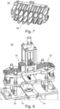
- Figs. 8 to 11 show a punching system 30 and details thereof.
- the punching system 30 comprises at least one punching tool 10 as described in the foregoing, and the conductor receiving element 20 as described in the foregoing, whereas in Fig. 8 the conductor receiving element 20 is hidden.
- the at least one punching tool 10 and the conductor receiving element 20 are configured such that the at least one punching tool 10 is slidingly guided in the at least one through hole which is at least partially blocked.
- the punching system 30 comprises a receptacle 31 in which the conductor receiving element 20 can be floatingly supported.
- the punching system 30 of Fig. 8 further comprises lift plates 32 and fixing plates 33.
- the lift plates 32 allow to lift punching tools 10 which are not required for a punching operation because exemplarily only one through hole of a plurality of through holes needs to be punched free.
- the respective punching tools 10 may be fixed in the upper position relative to the receptacle 31 by means of the fixing plates 33.
- the punching tools 10 which are intended to perform a punching operation move down towards the receptacle 31 within the punching tool guiding 34 when the punching is performed (cf. Figs. 10 and 11 ).
- the punching system 30 may comprise blow nozzles which blow against the punching end 11 of the at least one punching tool 10 after punching operation. Thus, residues at the punching end 11 may be reliably removed.
- a suction chamber may be provided below the receptacle 31 which serves to suck away the punched out components.
Landscapes
- Engineering & Computer Science (AREA)
- Mechanical Engineering (AREA)
- Life Sciences & Earth Sciences (AREA)
- Forests & Forestry (AREA)
- Manufacturing & Machinery (AREA)
- Perforating, Stamping-Out Or Severing By Means Other Than Cutting (AREA)
- Connector Housings Or Holding Contact Members (AREA)
Abstract
Description
- The present disclosure relates to a punching tool, a conductor receiving element, and a punching system comprising said punching tool and said conductor receiving element.
- For injection molded plastic components, it is often necessary to perform post-processing. For example, machining-related rework such as deburring or removal of sprues must be performed. However, various cases exist where post-processing must be performed to achieve a desired functionality of the injection molded component.
- For example, conductor receiving elements for electrical connectors are known which have a plurality of elongated through holes to receive electrical conductors such as cables and/or terminals. Regularly, at least some of these through holes are at least partially blocked by a blocking element, so that no electrical conductor can be passed through until the blocking element has been removed. With the aid of a corresponding punching tool, the blocking element can be removed in order to adapt the corresponding through hole so that an electrical conductor can be fed through. This makes it possible to customize the electrical connector using the conductor receiving element. For example, a conductor receiving element can be adapted to different numbers of conductors depending on how many blocking elements have been removed. For example, eight blocking elements can be removed from a conductor receiving element with twelve blocked through holes to provide an eight-pole electrical connector. To prevent the cable channel following a blocked through hole from being exposed and for example moisture from penetrating into the electrical connector, the blocking elements are each regularly connected to a corresponding sealing pin which protrudes out of the through hole, for example to close a hole in a collective sealing.
- The known punching tools and/or conductor receiving elements have the disadvantages that residues regularly remain in the component when the said blocking elements are removed (see
Fig. 12 ), damage to the through holes occurs in particular because of the punching tool, and/or a high punching force is required. - Thus, it is an object of the present disclosure to provide a punching tool, a conductor receiving element, and a punching system comprising said punching tool and said conductor receiving element that overcome the aforementioned drawbacks at least partially.
- This object is achieved, at least partly, by a punching tool, a conductor receiving element, and a punching system comprising said punching tool and said conductor receiving element, as defined in the independent claims. Further aspects of the present disclosure are defined in the dependent claims.
- In particular, the object is achieved by a punching tool for punching out at least one beam element with both ends attached to the inside surface of an elongated through hole, wherein the punching tool has an elongated shape with a punching end and a holding end. The punching end comprises a front surface for being inserted into the elongated through hole first, and at least one cutting edge which is spaced apart from the front surface along the longitudinal axis of the punching tool and extends substantially transverse to the longitudinal axis.
- The punching tool may be configured for punching polymer materials. Moreover, the punching tool may be adapted to be used without a die. Further, the punching tool may be integrally formed, whereas it is understood that the punching tool may also comprise separate parts being assembled. Preferably the punching tool is made of a metallic material such as steel, as this allows for longer durability.
- Further, the punching end may be referred to as the end of the punching tool which punches the respective material/element. Said holding end may be configured to be manually held and/or to be mounted within a respective punching system.
- The front surface is preferably substantially perpendicular to the longitudinal axis of the punching tool. This allows elements to be reliably pressed out of through holes and, in particular, avoids jamming. The front surface may comprise more than one individual surface. Exemplarily, the front surface may be divided by a groove and/or a recess into at least two separate surfaces which lie in the same plane.
- The at least one cutting edge may be also referred to as the at least one punching edge. The surfaces of the punching tool defining the at least one cutting edge preferably include an angle which lies in the range from 45° to 90°, preferably from 60° to 90°, further preferably from 80° to 90° and most preferably from 85° to 90°.
- By the at least one cutting edge being spaced apart from the front surface along the longitudinal axis of the punching tool and extending substantially transverse to the longitudinal axis a damage to the through hole because of the punching tool can be avoided. This is as first the front surface is inserted into the elongated through hole so that the punching tool is already at least partially guided when the at least one cutting edge is inserted. Hence an accidental cutting of the through hole by the at least one cutting edge can be reliably avoided.
- Optionally the minimum distance between the front surface and the at least one cutting edge lies in a range from 0.2 mm to 0.8 mm, preferably from 0.3 mm to 0.7 mm, and further preferably from 0.4 mm to 0.6 mm. These minimum distances have proven to be advantageous in that they allow for a sufficient guiding of the punching tool while at the same time avoiding an excessive length of the punching tool.
- The at least one cutting edge may be adjacent to a peripheral surface of the punching tool. The peripheral surface may represent a guiding surface of the punching tool which allows for a guided sliding in the elongated through hole. By the at least one cutting edge being adjacent to the peripheral surface an element being attached to the through hole in which the punching tool is inserted can be separated directly at the point of attachment. Thereby a bending and uncontrolled breaking can be avoided. Thus, residues in the respective through hole can be avoided or at least reduced.
- The at least one cutting edge may be inclined relative to the longitudinal axis of the punching tool, wherein preferably the inclination angle between the at least one cutting edge and the longitudinal axis lies in a range from 91° to 103°, preferably from 93° to 100°, and further preferably from 94° to 97°. It is to be noted that those ranges do not exclude that the at least one cutting edge extends substantially transverse to the longitudinal axis. By the at least one cutting edge being inclined relative to the longitudinal axis of the punching tool a cutting can be facilitated as a shear movement is favored.
- The punching end may comprise a recess being formed into the front surface along the longitudinal axis of the punching tool, wherein preferably the at least one cutting edge forms part of the recess. The recess preferably tapers from the front surface to the at least one cutting edge. Said recess can ensure that an element to be removed is first received in the punching end and stabilized therein before it is separated by the at least one trailing cutting edge. Moreover, by the recess tapering from the front surface to the at least one cutting edge the element to be removed can be particularly reliably received in the recess and guided to the cutting edge. The recess may have a variety of geometries, as set out in the following.
- The recess may have a T-shape, or an X-shape as seen in a direction from the punching end to the holding end. The T-shape allows to receive and cut out two beam elements which are connected to form a T-shape. Further, the X-shape allows to receive and cut out two beam elements which intersect to form an X-shape.
- The punching tool may comprise a flex portion arranged between the punching end and the holding end, wherein in the flex portion the cross-sectional area of the punching tool is reduced compared to portions of the punching tool being adjacent to the flex portion, wherein preferably in the flex portion the cross-sectional area continuously decreases to a minimum. The flex portion can increase flexibility between the two ends of the punching tool. Consequently, the transmission of bending loads through the punching tool is at least reduced. This means that if the punching tool has already been inserted into a through hole, a displacement of the holding end relative to the through hole and transverse to the longitudinal direction can be prevented from causing the punching end to tilt and thereby damaging the through hole. In summary, a more reliable punching can be achieved.
- The peripheral edge of the front surface may be rounded and/or beveled, wherein said peripheral edge is preferably substantially perpendicular to the longitudinal axis of the punching tool. It is understood that if the front surface is separated into two surfaces as mentioned above, the peripheral edge of the front surface can also be separated.
- The punching tool may comprise at least two, particularly at least three, and further particularly at least four, cutting edges configured as the at least one cutting edge described herein. As a result, also more complex components, which are fastened with several attachment points in a through hole, can be reliably removed. Preferably at least two of said cutting edges are arranged opposite to each other and are axially spaced apart from each other along the longitudinal axis. Thereby can be achieved that the element to be removed is subjected to at least two shearing operations at different times. This allows that an even more reliable punching can be achieved.
- Further, the above object is also achieved by a conductor receiving element for an electrical connector, wherein the conductor receiving element comprises a plurality of elongated through holes, wherein at least one through hole is at least partially blocked; a first beam element with a first end and a second end, wherein the first end and the second end are attached to the inside surface of the at least one through hole, and a sealing pin for sealing a hole of a collective sealing, wherein the sealing pin is attached to the first beam element and extends out of the at least one through hole.
- Preferably, through the at least one through hole being at least partially blocked no electrical conductor can be passed through until the first beam element has not been removed. With the aid of the punching tool described herein the first beam element and optionally the second beam element as mentioned in the following may be removed to adapt the at least one through hole so that an electrical conductor can be fed through.
- By using the conductor receiving element it is possible to customize an electrical connector. Exemplarily, a conductor receiving element with multiple blocked through holes can be adapted to a different number of conductors depending on how many blocking elements are removed. For example, eight first beam elements can be removed from a conductor receiving element with twelve through holes being blocked by respective first beam elements to provide an eight-pole electrical connector.
- The sealing pin may allow to prevent a cable channel following a through hole being blocked from being exposed and for example moisture from penetrating into the respective electrical connector.
- Further, the conductor receiving element may be integrally formed with the first beam element. Exemplarily by means of injection molding.
- The first beam element is preferably linear. This has shown to facilitate removal. However, it is also conceivable that the first beam element is curved and/or angled. Further, the first beam element may have a substantially rectangular cross-section. "Substantially" in this context means that the edges may be rounded, as it is exemplarily required for injection molded parts. Preferably, the first beam element is distinctly identifiable between the first end and the second end at any position. This is also the case if the first beam element intersects another beam element or has a kink.
- It is understood that of the plurality of elongated through holes, multiple or even all through holes may be at least partially blocked.
- The first beam element and the sealing pin preferably do not intersect. Exemplarily, if the sealing pin has a cylindrical shape and the first beam element substantially has the shape of a rectangular cuboid, then a base area of the cylindrical shape may be attached to the outside of the rectangular cuboid shape of the first beam element. Particularly, said rectangular cuboid shape and said cylindrical shape may be integrally formed. However, the rectangular cuboid shape may not protrude through the cylindrical shape. In particular, the first beam element and the sealing pin preferably do not define a section volume. The first beam element and the sealing pin not intersecting with each other has at least two advantages. First, this configuration allows that the manufacture of the conductor receiving element is simplified. The fact that the first beam element and the sealing pin do not intersect means that there is a separation plane, which allows for simpler design of the mold cores for injection molding. Secondly, this configuration has proven to be advantageous in that it promotes more reliable separation of the first beam element compared to cases where the first beam element and the sealing pin intersect.
- The conductor receiving element may comprise a second beam element with a first end and a second end, wherein the first beam element and the second beam element intersect, wherein the first end and the second end of the second beam element are attached to the inside surface of the at least one through hole. Preferably, the first beam element and the second beam element form an X-shape. This shape has proven to be particularly stable and at the same time easy to remove.
- Alternatively, the conductor receiving element may comprise a second beam element with a first end and a second end, wherein the first end of the second beam element is attached to the inside surface of the at least one through hole and the second end of the second beam element is attached to the first beam element. Preferably, the first beam element and the second beam element form a T-shape. This shape has proven to be particularly easy to remove and at the same time allows for a sufficient level of stability.
- Furthermore, it is understood that the second beam element may be configured as the first beam element.
- The sealing pin may be attached to the first beam element and the second beam element, wherein the first beam element and the second beam element preferably do not intersect with the sealing pin. Exemplarily, if the sealing pin has a cylindrical shape and the beam elements substantially each have the shape of a rectangular cuboid, then a base area of the cylindrical shape may be attached to the outside of the rectangular cuboid shape of the beam elements. As above, said rectangular cuboid shapes and said cylindrical shape may be integrally formed, whereas the rectangular cuboid shapes may not protrude through the cylindrical shape. In particular, the beam elements and the sealing pin preferably do not define a section volume. It has shown that by the sealing pin being attached to the first beam element and the second beam element the stability and/or stiffness of the sealing pin within the respective through hole may be enhanced.
- Moreover, the above object is also achieved by a punching system comprising at least one punching tool as described herein, and the conductor receiving element as described herein, wherein the at least one punching tool and the conductor receiving element are configured such that the at least one punching tool is slidingly guided in the at least one through hole which is at least partially blocked. Exemplarily, the peripheral surface of the punching tool may be configured to be slidingly guided by the inside surface of the at least one through hole.
- The punching system preferably further comprises a receptacle in which the conductor receiving element can be floatingly supported. This allows inaccuracies regarding the positioning of the punching tool relative to the conductor receiving element to be compensated. This makes it possible to achieve precise guidance of the punching tool in the corresponding through hole and to ensure that any tolerance-related offset of the punching tool relative to the conductor receiving element does not lead to damage.
- Further, the punching system is configured such that the height of the first and/or second beam element measured along the at least one through hole being at least partially blocked is larger than the distance by which the at least one cutting edge is spaced apart from the front surface along the longitudinal axis of the punching tool. Hence, a contact of the punching tool with the sealing pin can be avoided which ensures a reliable punching operation.
- In the following, the accompanying figures are briefly described:
-
Fig. 1 shows a punching tool according to the present invention in perspective view; -
Fig. 2 shows a detail perspective view of the punching end of the punching tool; -
Fig. 3 shows a detail side view of the punching end of the punching tool; -
Fig. 4 shows a conductor receiving element according to the present invention in top view; -
Fig. 5 shows a detail ofFig. 4 ; -
Fig. 6 shows a detail of a perspective view of the conductor receiving element; -
Fig. 7 shows a perspective view of the conductor receiving element; -
Fig. 8 shows a punching system according to the present invention in perspective view; -
Fig. 9 shows a detail of the receptacle of the punching system ofFig. 8 ; -
Fig. 10 shows the punching system in perspective view prior to punching; -
Fig. 11 shows the punching system in perspective view during punching, and -
Fig. 12 shows a prior art conductor receiving element. -
Fig. 1 shows apunching tool 10 for punching out at least onebeam element 22 with both ends 23, 24 attached to the inside surface of an elongated throughhole 21c (seeFig. 4 ). Thepunching tool 10 has an elongated shape with a punchingend 11 and a holdingend 12. Thepunching tool 10 comprises aflex portion 18 arranged between the punchingend 11 and the holdingend 12, wherein in theflex portion 18 the cross-sectional area of thepunching tool 10 is reduced compared to portions of thepunching tool 10 being adjacent to theflex portion 18. Particularly, in theflex portion 18 the cross-sectional area continuously decreases to a minimum. - The punching
end 11 is depicted in detail inFigs. 2 and3 . Said punchingend 11 comprises afront surface 13 for being inserted into the elongated through hole first. FromFig. 2 particularly it is understood that thefront surface 13 is segmented into four surfaces which lie in one plane. Further, the punchingend 11 comprises fourcutting edges front surface 13 along thelongitudinal axis 17 of thepunching tool 10 and extend substantially transverse to thelongitudinal axis 17. - As depicted in
Fig. 2 , thecutting edges peripheral surface 15 of thepunching tool 10. Moreover, the punchingend 11 comprises arecess 16 being formed into thefront surface 13 along thelongitudinal axis 17 of thepunching tool 10, wherein thecutting edges recess 16. Saidrecess 16 has an X-shape as seen in a direction from the punchingend 11 to the holdingend 12. Further, saidrecess 16 tapers from thefront surface 13 to the fourcutting edges peripheral edge 19 of thefront surface 13 is rounded, wherein said roundedperipheral edge 19 is substantially perpendicular to thelongitudinal axis 17 of thepunching tool 10. - As depicted in detail in
Fig. 3 the cutting edges 14b and 14d are inclined relative to thelongitudinal axis 17 of thepunching tool 10, wherein the inclination angle α between the cuttingedges longitudinal axis 17 lies in a range from 94° to 97°. Further, as also depicted inFig. 3 , the cuttingedges longitudinal axis 17. Moreover, all cuttingedges planar surface 140. -
Figs. 4 to 7 show aconductor receiving element 20 for an electrical connector. Theconductor receiving element 20 comprises a plurality of elongated throughholes holes conductor receiving element 20 further comprises afirst beam element 22 with afirst end 23 and asecond end 24, wherein thefirst end 23 and thesecond end 24 are attached to the inside surface of the blocked throughhole 21c. It is understood that the throughholes conductor receiving element 20 comprises a sealingpin 28 for sealing a hole of a collective sealing, wherein the sealingpin 28 is attached to thefirst beam element 22 and extends out of the throughhole 21c. The other sealing pins are not numbered for the sake of simplicity. - Further, the
conductor receiving element 20 comprises asecond beam element 25 with afirst end 26 and asecond end 27, wherein thefirst beam element 22 and thesecond beam element 25 intersect, wherein thefirst end 26 and thesecond end 27 of thesecond beam element 25 are attached to the inside surface of the at least one throughhole 21c. Thereby the sealingpin 28 is attached to thefirst beam element 22 and thesecond beam element 25, wherein thefirst beam element 22 and thesecond beam element 25 do not intersect with the sealingpin 28. -
Figs. 8 to 11 show apunching system 30 and details thereof. The punchingsystem 30 comprises at least onepunching tool 10 as described in the foregoing, and theconductor receiving element 20 as described in the foregoing, whereas inFig. 8 theconductor receiving element 20 is hidden. As shown inFigs. 10 and 11 , the at least onepunching tool 10 and theconductor receiving element 20 are configured such that the at least onepunching tool 10 is slidingly guided in the at least one through hole which is at least partially blocked. Further, as depicted in detail inFig. 9 , the punchingsystem 30 comprises areceptacle 31 in which theconductor receiving element 20 can be floatingly supported. - The punching
system 30 ofFig. 8 further compriseslift plates 32 and fixingplates 33. Thelift plates 32 allow to liftpunching tools 10 which are not required for a punching operation because exemplarily only one through hole of a plurality of through holes needs to be punched free. When lifted by thelift plates 32 therespective punching tools 10 may be fixed in the upper position relative to thereceptacle 31 by means of the fixingplates 33. Thus, only thepunching tools 10 which are intended to perform a punching operation move down towards thereceptacle 31 within the punching tool guiding 34 when the punching is performed (cf.Figs. 10 and 11 ). - Further, even though not explicitly depicted in the Figs., the punching
system 30 may comprise blow nozzles which blow against the punchingend 11 of the at least onepunching tool 10 after punching operation. Thus, residues at the punchingend 11 may be reliably removed. Moreover, a suction chamber may be provided below thereceptacle 31 which serves to suck away the punched out components. -
- 10
- punching tool
- 11
- punching end
- 12
- holding end
- 13
- front surface
- 14a, 14b, 14c, 14d
- cutting edges
- 15
- peripheral surface
- 16
- recess
- 17
- longitudinal axis
- 18
- flex portion
- 19
- peripheral edge
- α
- inclination angle between cutting edge and longitudinal axis
- 140
- planar surface
- 20
- conductor receiving element
- 21a, 21b, 21c, 21d, 21e, 21f
- elongated through holes
- 22
- first beam element
- 23
- first end of the first beam element
- 24
- second end of the first beam element
- 25
- second beam element
- 26
- first end of the second beam element
- 27
- second end of the second beam element
- 28
- sealing pin
- 30
- punching system
- 31
- receptacle
- 32
- lift plates
- 33
- fixing plates
- 34
- punching tool guiding
Claims (15)
- A punching tool (10) for punching out at least one beam element (22) with both ends (23, 24) attached to the inside surface of an elongated through hole (21c), wherein the punching tool (10) has an elongated shape with a punching end (11) and a holding end (12), wherein the punching end (11) comprisesa front surface (13) for being inserted into the elongated through hole first, andat least one cutting edge (14a, 14b, 14c, 14d) which is spaced apart from the front surface (13) along the longitudinal axis (17) of the punching tool (10) and extends substantially transverse to the longitudinal axis (17).
- The punching tool (10) according to the preceding claim, wherein the at least one cutting edge (14a, 14b, 14c, 14d) is adjacent to a peripheral surface (15) of the punching tool (10).
- The punching tool (10) according to any one of the preceding claims, wherein the at least one cutting edge (14a, 14b, 14c, 14d) is inclined relative to the longitudinal axis (17) of the punching tool (10), wherein preferably the inclination angle (α) between the at least one cutting edge (14a, 14b, 14c, 14d) and the longitudinal axis (17) lies in a range from 91° to 103°, preferably from 93° to 100°, and further preferably from 94° to 97°.
- The punching tool (10) according to any one of the preceding claims, wherein the punching end (11) comprises a recess (16) being formed into the front surface (13) along the longitudinal axis (17) of the punching tool (10), wherein preferably the at least one cutting edge (14a, 14b, 14c, 14d) forms part of the recess (16), wherein further preferably the recess (16) tapers from the front surface (13) to the at least one cutting edge (14a, 14b, 14c, 14d).
- The punching tool (10) according to the preceding claim, wherein the recess (16) has a T-shape, or an X-shape as seen in a direction from the punching end (11) to the holding end (12).
- The punching tool (10) according to any one of the preceding claims, wherein the punching tool (10) comprises a flex portion (18) arranged between the punching end (11) and the holding end (12), wherein in the flex portion (18) the cross-sectional area of the punching tool (10) is reduced compared to portions of the punching tool (10) being adjacent to the flex portion (18), wherein preferably in the flex portion (18) the cross-sectional area continuously decreases to a minimum.
- The punching tool (10) according to any one of the preceding claims, wherein the peripheral edge (19) of the front surface (13) is rounded and/or beveled, wherein said peripheral edge (19) is preferably substantially perpendicular to the longitudinal axis (17) of the punching tool (10).
- The punching tool (10) according to any one of the preceding claims, wherein the punching tool (10) comprises at least two, particularly at least three, and further particularly at least four, cutting edges (14a, 14b, 14c, 14d) being configured as the at least one cutting edge (14a, 14b, 14c, 14d) according to the preceding claims, wherein preferably at least two of said cutting edges (14b, 14d) are arranged opposite to each other and are axially spaced apart from each other along the longitudinal axis (17).
- A conductor receiving element (20) for an electrical connector, wherein the conductor receiving element (20) comprisesa plurality of elongated through holes (21a, 21b, 21c, 21d, 21e, 21f), wherein at least one through hole (21c) is at least partially blocked;a first beam element (22) with a first end (23) and a second end (24), wherein the first end (23) and the second end (24) are attached to the inside surface of the at least one through hole (21c), anda sealing pin (28) for sealing a hole of a collective sealing, wherein the sealing pin (28) is attached to the first beam element (22) and extends out of the at least one through hole (21c).
- The conductor receiving element (20) according to the preceding claim, wherein the first beam element (22) and the sealing pin (28) do not intersect.
- The conductor receiving element (20) according to any one of claims 9 or 10, wherein the conductor receiving element (20) comprises a second beam element (25) with a first end (26) and a second end (27), wherein the first beam element (22) and the second beam element (25) intersect, wherein the first end (26) and the second end (27) of the second beam element (25) are attached to the inside surface of the at least one through hole (21c).
- The conductor receiving element (20) according to any one of claims 9 or 10, wherein the conductor receiving element (20) comprises a second beam element with a first end and a second end, wherein the first end of the second beam element is attached to the inside surface of the at least one through hole and the second end of the second beam element is attached to the first beam element.
- The conductor receiving element (20) according to any one of claims 11 or 12, wherein the sealing pin (28) is attached to the first beam element (22) and the second beam element (25), wherein the first beam element (22) and the second beam element (25) preferably do not intersect with the sealing pin (28).
- A punching system (30) comprisingat least one punching tool (10) according to any one of claims 1 to 8, andthe conductor receiving element (20) according to any one of claims 9 to 13, wherein the at least one punching tool (10) and the conductor receiving element (20) are configured such that the at least one punching tool (10) is slidingly guided in the at least one through hole (21c) which is at least partially blocked.
- The punching system (30) according to the preceding claim, wherein the punching system (30) further comprises a receptacle (31) in which the conductor receiving element (20) can be floatingly supported.
Priority Applications (3)
| Application Number | Priority Date | Filing Date | Title |
|---|---|---|---|
| EP23165003.7A EP4438256B1 (en) | 2023-03-29 | 2023-03-29 | Punching tool |
| US18/604,877 US20240326277A1 (en) | 2023-03-29 | 2024-03-14 | Punching tool |
| CN202410365431.1A CN118721292A (en) | 2023-03-29 | 2024-03-28 | Punching tools |
Applications Claiming Priority (1)
| Application Number | Priority Date | Filing Date | Title |
|---|---|---|---|
| EP23165003.7A EP4438256B1 (en) | 2023-03-29 | 2023-03-29 | Punching tool |
Publications (2)
| Publication Number | Publication Date |
|---|---|
| EP4438256A1 true EP4438256A1 (en) | 2024-10-02 |
| EP4438256B1 EP4438256B1 (en) | 2026-01-28 |
Family
ID=85781714
Family Applications (1)
| Application Number | Title | Priority Date | Filing Date |
|---|---|---|---|
| EP23165003.7A Active EP4438256B1 (en) | 2023-03-29 | 2023-03-29 | Punching tool |
Country Status (3)
| Country | Link |
|---|---|
| US (1) | US20240326277A1 (en) |
| EP (1) | EP4438256B1 (en) |
| CN (1) | CN118721292A (en) |
Citations (4)
| Publication number | Priority date | Publication date | Assignee | Title |
|---|---|---|---|---|
| WO2008122844A1 (en) * | 2007-04-06 | 2008-10-16 | Fci | Electrical connector and method of manufacture |
| WO2017178647A1 (en) * | 2016-04-15 | 2017-10-19 | Te Connectivity Germany Gmbh | Electric plug connector for insertion onto a pcb and for being affixed to the pcb by means of a casting compound and method therefor |
| EP3236537A1 (en) * | 2016-04-22 | 2017-10-25 | Yazaki North America, Inc. | Cable seal connector with punch-out capability for unused cavities |
| US10897103B1 (en) * | 2019-09-12 | 2021-01-19 | Aptiv Technologies Limited | Electrical connector with seal protection |
-
2023
- 2023-03-29 EP EP23165003.7A patent/EP4438256B1/en active Active
-
2024
- 2024-03-14 US US18/604,877 patent/US20240326277A1/en active Pending
- 2024-03-28 CN CN202410365431.1A patent/CN118721292A/en active Pending
Patent Citations (4)
| Publication number | Priority date | Publication date | Assignee | Title |
|---|---|---|---|---|
| WO2008122844A1 (en) * | 2007-04-06 | 2008-10-16 | Fci | Electrical connector and method of manufacture |
| WO2017178647A1 (en) * | 2016-04-15 | 2017-10-19 | Te Connectivity Germany Gmbh | Electric plug connector for insertion onto a pcb and for being affixed to the pcb by means of a casting compound and method therefor |
| EP3236537A1 (en) * | 2016-04-22 | 2017-10-25 | Yazaki North America, Inc. | Cable seal connector with punch-out capability for unused cavities |
| US10897103B1 (en) * | 2019-09-12 | 2021-01-19 | Aptiv Technologies Limited | Electrical connector with seal protection |
Also Published As
| Publication number | Publication date |
|---|---|
| CN118721292A (en) | 2024-10-01 |
| US20240326277A1 (en) | 2024-10-03 |
| EP4438256B1 (en) | 2026-01-28 |
Similar Documents
| Publication | Publication Date | Title |
|---|---|---|
| US4964812A (en) | Wire termination block | |
| US3998514A (en) | Device armed with a terminal for making electrical connection with a conductor | |
| EP1738436B1 (en) | A cap, a termination assembly and a housing assembly for a modular telecom connection jack | |
| EP0337659A1 (en) | Solder post retention means | |
| EP0392193A2 (en) | A connector for cables | |
| EP2477277A1 (en) | Joint connector, busbar and assembling method therefor | |
| EP2256867A1 (en) | Electrical Connector | |
| EP3273549A1 (en) | Connector with separable lacing fixture | |
| EP1662617A1 (en) | Connection terminal | |
| EP0643440A2 (en) | Electrical connectors | |
| EP2416452A1 (en) | Terminal fitting | |
| US7357661B2 (en) | Pressure coupling connector | |
| EP4438256B1 (en) | Punching tool | |
| SE428982B (en) | ELECTRICAL CONTACT DEVICE | |
| EP1661210B1 (en) | Cable connector | |
| EP2498346A1 (en) | Coaxial connector for substrate, pair of chain terminal, and method of manufacturing coaxial connector for substrate | |
| EP2073318A1 (en) | Terminal fitting insertion guide structure and electrical connector | |
| EP1662616B1 (en) | Connection assembly for electrical cables, of the type for connection to connectors with cylindrical-pin terminals | |
| GB1558811A (en) | Electrical connentors | |
| KR102949175B1 (en) | A plug equipped with a guide plate | |
| CN115966983B (en) | cutter | |
| KR20020079427A (en) | Electric connector terminal and terminal element with carrier | |
| CN113270774B (en) | Shorting pin, plug connector with such a shorting pin, and method for producing such a shorting pin | |
| CN114762195B (en) | Socket body | |
| JP4577405B2 (en) | connector |
Legal Events
| Date | Code | Title | Description |
|---|---|---|---|
| PUAI | Public reference made under article 153(3) epc to a published international application that has entered the european phase |
Free format text: ORIGINAL CODE: 0009012 |
|
| STAA | Information on the status of an ep patent application or granted ep patent |
Free format text: STATUS: THE APPLICATION HAS BEEN PUBLISHED |
|
| AK | Designated contracting states |
Kind code of ref document: A1 Designated state(s): AL AT BE BG CH CY CZ DE DK EE ES FI FR GB GR HR HU IE IS IT LI LT LU LV MC ME MK MT NL NO PL PT RO RS SE SI SK SM TR |
|
| STAA | Information on the status of an ep patent application or granted ep patent |
Free format text: STATUS: REQUEST FOR EXAMINATION WAS MADE |
|
| 17P | Request for examination filed |
Effective date: 20250401 |
|
| GRAP | Despatch of communication of intention to grant a patent |
Free format text: ORIGINAL CODE: EPIDOSNIGR1 |
|
| STAA | Information on the status of an ep patent application or granted ep patent |
Free format text: STATUS: GRANT OF PATENT IS INTENDED |
|
| INTG | Intention to grant announced |
Effective date: 20250818 |
|
| GRAS | Grant fee paid |
Free format text: ORIGINAL CODE: EPIDOSNIGR3 |
|
| GRAA | (expected) grant |
Free format text: ORIGINAL CODE: 0009210 |
|
| STAA | Information on the status of an ep patent application or granted ep patent |
Free format text: STATUS: THE PATENT HAS BEEN GRANTED |
|
| AK | Designated contracting states |
Kind code of ref document: B1 Designated state(s): AL AT BE BG CH CY CZ DE DK EE ES FI FR GB GR HR HU IE IS IT LI LT LU LV MC ME MK MT NL NO PL PT RO RS SE SI SK SM TR |
|
| REG | Reference to a national code |
Ref country code: CH Ref legal event code: F10 Free format text: ST27 STATUS EVENT CODE: U-0-0-F10-F00 (AS PROVIDED BY THE NATIONAL OFFICE) Effective date: 20260128 Ref country code: GB Ref legal event code: FG4D |
|
| REG | Reference to a national code |
Ref country code: DE Ref legal event code: R096 Ref document number: 602023011150 Country of ref document: DE |
|
| P01 | Opt-out of the competence of the unified patent court (upc) registered |
Free format text: CASE NUMBER: UPC_APP_0001135_4438256/2026 Effective date: 20260113 |
|
| REG | Reference to a national code |
Ref country code: IE Ref legal event code: FG4D |
|
| PGFP | Annual fee paid to national office [announced via postgrant information from national office to epo] |
Ref country code: DE Payment date: 20260211 Year of fee payment: 4 |
|
| PGFP | Annual fee paid to national office [announced via postgrant information from national office to epo] |
Ref country code: AT Payment date: 20260301 Year of fee payment: 4 |
|
| PGFP | Annual fee paid to national office [announced via postgrant information from national office to epo] |
Ref country code: FR Payment date: 20260212 Year of fee payment: 4 |
|
| REG | Reference to a national code |
Ref country code: NL Ref legal event code: MP Effective date: 20260128 |
|
| PG25 | Lapsed in a contracting state [announced via postgrant information from national office to epo] |
Ref country code: NL Free format text: LAPSE BECAUSE OF FAILURE TO SUBMIT A TRANSLATION OF THE DESCRIPTION OR TO PAY THE FEE WITHIN THE PRESCRIBED TIME-LIMIT Effective date: 20260128 |
|
| REG | Reference to a national code |
Ref country code: AT Ref legal event code: MK05 Ref document number: 1880622 Country of ref document: AT Kind code of ref document: T Effective date: 20260128 |
|
| PG25 | Lapsed in a contracting state [announced via postgrant information from national office to epo] |
Ref country code: RS Free format text: LAPSE BECAUSE OF FAILURE TO SUBMIT A TRANSLATION OF THE DESCRIPTION OR TO PAY THE FEE WITHIN THE PRESCRIBED TIME-LIMIT Effective date: 20260428 |
|
| PG25 | Lapsed in a contracting state [announced via postgrant information from national office to epo] |
Ref country code: ES Free format text: LAPSE BECAUSE OF FAILURE TO SUBMIT A TRANSLATION OF THE DESCRIPTION OR TO PAY THE FEE WITHIN THE PRESCRIBED TIME-LIMIT Effective date: 20260128 |
|
| PG25 | Lapsed in a contracting state [announced via postgrant information from national office to epo] |
Ref country code: PL Free format text: LAPSE BECAUSE OF FAILURE TO SUBMIT A TRANSLATION OF THE DESCRIPTION OR TO PAY THE FEE WITHIN THE PRESCRIBED TIME-LIMIT Effective date: 20260128 |
|
| PG25 | Lapsed in a contracting state [announced via postgrant information from national office to epo] |
Ref country code: GR Free format text: LAPSE BECAUSE OF FAILURE TO SUBMIT A TRANSLATION OF THE DESCRIPTION OR TO PAY THE FEE WITHIN THE PRESCRIBED TIME-LIMIT Effective date: 20260429 |
|
| REG | Reference to a national code |
Ref country code: LT Ref legal event code: MG9D |
|
| PG25 | Lapsed in a contracting state [announced via postgrant information from national office to epo] |
Ref country code: LT Free format text: LAPSE BECAUSE OF FAILURE TO SUBMIT A TRANSLATION OF THE DESCRIPTION OR TO PAY THE FEE WITHIN THE PRESCRIBED TIME-LIMIT Effective date: 20260128 |
|
| PG25 | Lapsed in a contracting state [announced via postgrant information from national office to epo] |
Ref country code: NO Free format text: LAPSE BECAUSE OF FAILURE TO SUBMIT A TRANSLATION OF THE DESCRIPTION OR TO PAY THE FEE WITHIN THE PRESCRIBED TIME-LIMIT Effective date: 20260428 |
|
| PG25 | Lapsed in a contracting state [announced via postgrant information from national office to epo] |
Ref country code: AT Free format text: LAPSE BECAUSE OF FAILURE TO SUBMIT A TRANSLATION OF THE DESCRIPTION OR TO PAY THE FEE WITHIN THE PRESCRIBED TIME-LIMIT Effective date: 20260128 Ref country code: SE Free format text: LAPSE BECAUSE OF FAILURE TO SUBMIT A TRANSLATION OF THE DESCRIPTION OR TO PAY THE FEE WITHIN THE PRESCRIBED TIME-LIMIT Effective date: 20260128 Ref country code: FI Free format text: LAPSE BECAUSE OF FAILURE TO SUBMIT A TRANSLATION OF THE DESCRIPTION OR TO PAY THE FEE WITHIN THE PRESCRIBED TIME-LIMIT Effective date: 20260128 |
|
| PG25 | Lapsed in a contracting state [announced via postgrant information from national office to epo] |
Ref country code: HR Free format text: LAPSE BECAUSE OF FAILURE TO SUBMIT A TRANSLATION OF THE DESCRIPTION OR TO PAY THE FEE WITHIN THE PRESCRIBED TIME-LIMIT Effective date: 20260128 |
|
| PG25 | Lapsed in a contracting state [announced via postgrant information from national office to epo] |
Ref country code: PT Free format text: LAPSE BECAUSE OF FAILURE TO SUBMIT A TRANSLATION OF THE DESCRIPTION OR TO PAY THE FEE WITHIN THE PRESCRIBED TIME-LIMIT Effective date: 20260528 Ref country code: IS Free format text: LAPSE BECAUSE OF FAILURE TO SUBMIT A TRANSLATION OF THE DESCRIPTION OR TO PAY THE FEE WITHIN THE PRESCRIBED TIME-LIMIT Effective date: 20260528 |
|
| PG25 | Lapsed in a contracting state [announced via postgrant information from national office to epo] |
Ref country code: LV Free format text: LAPSE BECAUSE OF FAILURE TO SUBMIT A TRANSLATION OF THE DESCRIPTION OR TO PAY THE FEE WITHIN THE PRESCRIBED TIME-LIMIT Effective date: 20260128 |
|
| PG25 | Lapsed in a contracting state [announced via postgrant information from national office to epo] |
Ref country code: BG Free format text: LAPSE BECAUSE OF FAILURE TO SUBMIT A TRANSLATION OF THE DESCRIPTION OR TO PAY THE FEE WITHIN THE PRESCRIBED TIME-LIMIT Effective date: 20260128 |