EP4438233A1 - Power tool - Google Patents
Power tool Download PDFInfo
- Publication number
- EP4438233A1 EP4438233A1 EP24154304.0A EP24154304A EP4438233A1 EP 4438233 A1 EP4438233 A1 EP 4438233A1 EP 24154304 A EP24154304 A EP 24154304A EP 4438233 A1 EP4438233 A1 EP 4438233A1
- Authority
- EP
- European Patent Office
- Prior art keywords
- power
- mode
- circuit
- preset time
- detection module
- Prior art date
- Legal status (The legal status is an assumption and is not a legal conclusion. Google has not performed a legal analysis and makes no representation as to the accuracy of the status listed.)
- Granted
Links
Images

Classifications
-
- B—PERFORMING OPERATIONS; TRANSPORTING
- B25—HAND TOOLS; PORTABLE POWER-DRIVEN TOOLS; MANIPULATORS
- B25F—COMBINATION OR MULTI-PURPOSE TOOLS NOT OTHERWISE PROVIDED FOR; DETAILS OR COMPONENTS OF PORTABLE POWER-DRIVEN TOOLS NOT PARTICULARLY RELATED TO THE OPERATIONS PERFORMED AND NOT OTHERWISE PROVIDED FOR
- B25F5/00—Details or components of portable power-driven tools not particularly related to the operations performed and not otherwise provided for
-
- B—PERFORMING OPERATIONS; TRANSPORTING
- B23—MACHINE TOOLS; METAL-WORKING NOT OTHERWISE PROVIDED FOR
- B23Q—DETAILS, COMPONENTS, OR ACCESSORIES FOR MACHINE TOOLS, e.g. ARRANGEMENTS FOR COPYING OR CONTROLLING; MACHINE TOOLS IN GENERAL CHARACTERISED BY THE CONSTRUCTION OF PARTICULAR DETAILS OR COMPONENTS; COMBINATIONS OR ASSOCIATIONS OF METAL-WORKING MACHINES, NOT DIRECTED TO A PARTICULAR RESULT
- B23Q11/00—Accessories fitted to machine tools for keeping tools or parts of the machine in good working condition or for cooling work; Safety devices specially combined with or arranged in, or specially adapted for use in connection with, machine tools
- B23Q11/0078—Safety devices protecting the operator, e.g. against accident or noise
- B23Q11/0085—Safety devices protecting the operator, e.g. against accident or noise by determining whether the machine tool is in a dangerous configuration
-
- H—ELECTRICITY
- H02—GENERATION; CONVERSION OR DISTRIBUTION OF ELECTRIC POWER
- H02H—EMERGENCY PROTECTIVE CIRCUIT ARRANGEMENTS
- H02H7/00—Emergency protective circuit arrangements specially adapted for specific types of electric machines or apparatus or for sectionalised protection of cable or line systems, and effecting automatic switching in the event of an undesired change from normal working conditions
- H02H7/08—Emergency protective circuit arrangements specially adapted for specific types of electric machines or apparatus or for sectionalised protection of cable or line systems, and effecting automatic switching in the event of an undesired change from normal working conditions for dynamo-electric motors
- H02H7/09—Emergency protective circuit arrangements specially adapted for specific types of electric machines or apparatus or for sectionalised protection of cable or line systems, and effecting automatic switching in the event of an undesired change from normal working conditions for dynamo-electric motors against over-voltage; against reduction of voltage; against phase interruption
-
- B—PERFORMING OPERATIONS; TRANSPORTING
- B27—WORKING OR PRESERVING WOOD OR SIMILAR MATERIAL; NAILING OR STAPLING MACHINES IN GENERAL
- B27G—ACCESSORY MACHINES OR APPARATUS FOR WORKING WOOD OR SIMILAR MATERIALS; TOOLS FOR WORKING WOOD OR SIMILAR MATERIALS; SAFETY DEVICES FOR WOOD WORKING MACHINES OR TOOLS
- B27G19/00—Safety guards or devices specially adapted for wood saws; Auxiliary devices facilitating proper operation of wood saws
- B27G19/02—Safety guards or devices specially adapted for wood saws; Auxiliary devices facilitating proper operation of wood saws for circular saws
- B27G19/04—Safety guards or devices specially adapted for wood saws; Auxiliary devices facilitating proper operation of wood saws for circular saws for manually-operated power-driven circular saws
Definitions
- the present application relates to the field of electronic technologies and, in particular, to a power tool.
- Power tools such as a miter saw or an angle grinder have relatively high inertia. Therefore, the motor of this type of power tool coasts for a relatively long time after power-off. If a user turns on a switch and the power tool is powered again during the coast time of the motor after the power-off, the power tool may be caused to run again, thus causing a great security risk to an unprepared person near the power tool.
- an object of the present application is to provide a power tool and a power-off protection method thereof.
- a power tool includes a motor, a power terminal, a detection module, and a controller.
- the power terminal is configured to access a power supply of a battery pack.
- the detection module is capable of detecting that a first circuit between the power terminal and the battery pack is in a power-on mode or a power-off mode.
- the controller is capable of controlling a second circuit between the power terminal and the motor to be in a power-on mode or a power-off mode.
- the controller is configured to, when the detection module detects that the first circuit is switched from the power-on mode to the power-off mode, control the second circuit to be in the power-off mode within a first preset time.
- the controller is configured to, when the detection module detects, within the first preset time, that the first circuit is in the power-on mode again, control the second circuit to be in the power-off mode within the first preset time.
- the controller is configured to, when the detection module detects, outside the first preset time, that the first circuit is in the power-on mode, control the second circuit to be in the power-on mode.
- the power tool further includes an operation switch capable of controlling the second circuit to be in the power-on mode or the power-off mode, where the controller controls the second circuit to be in the power-off mode when the operation switch is in the off state.
- the power tool further includes an operation switch capable of controlling the second circuit to be in the power-on mode or the power-off mode, where the second circuit is in the power-off mode when the operation switch is in the off state, and the controller controls the second circuit to be in the power-on mode or the power-off mode when the operation switch is in the on state.
- the controller is configured to, when the operation switch is in the on state within the first preset time and the detection module detects, within the first preset time, that the first circuit is in the power-on mode again, control the second circuit to be in the power-off mode within the first preset time.
- the controller is configured to, when the operation switch is in the on state outside the first preset time and the detection module detects, outside the first preset time, that the first circuit is in the power-on mode, control the second circuit to be in the power-on mode.
- the controller is configured to, when the operation switch is switched from the off state to the on state within the first preset time and the detection module detects, within the first preset time, that the first circuit is in the power-on mode again, control the second circuit to be in the power-off mode within the first preset time.
- the power tool further includes a communication terminal configured to perform data communication with the battery pack, where the detection module is capable of detecting whether a level of the communication terminal varies.
- the detection module determines, based on whether the level of the communication terminal varies, that the first circuit is in the power-on mode or the power-off mode.
- the detection module is also capable of detecting a phase current of the motor and determining, based on the magnitude of the phase current of the motor, that the first circuit is in the power-on mode or the power-off mode.
- the detection module is also capable of detecting a phase current of the motor.
- the detection module is configured to, when the absolute value of the phase current of the motor is less than a preset current threshold and the level of the communication terminal does not vary within a second preset time, determine that the first circuit is in the power-off mode.
- the detection module is also capable of detecting a back electromotive force of the motor and a bus voltage of the motor.
- the detection module is configured to, when the difference between the back electromotive force of the motor and the bus voltage of the motor is less than a preset voltage threshold within a third preset time, determine that the first circuit is in the power-off mode.
- the battery pack is plugged into the power tool, where the first circuit is in the power-on mode when the battery pack is plugged into the power tool, and the first circuit is in the power-off mode when the battery pack is pulled out of the power tool.
- the first preset time is greater than or equal to a coast time of the motor.
- a power tool includes: a motor; a power terminal configured to access a power supply of a battery pack; a detection module capable of detecting that a first circuit between the power terminal and the battery pack is in a power-on mode or a power-off mode; and a controller capable of controlling a second circuit between the power terminal and the motor to be in a power-on mode or a power-off mode.
- the controller is configured to, when the detection module detects that the first circuit is switched from the power-off mode to the power-on mode, control the second circuit to be in the power-off mode if a time when the first circuit is in the power-off mode before the switchover does not exceed a first preset time.
- the first preset time is greater than or equal to 2 seconds and less than or equal to 10 seconds.
- the controller is configured to, when the detection module detects that the first circuit is switched from the power-off mode to the power-on mode, control the second circuit to be in the power-on mode if a time when the first circuit is in the power-off mode before the switchover exceeds the first preset time.
- the power tool further includes an operation switch, where the controller is configured to, when the detection module detects that the first circuit is switched from the power-off mode to the power-on mode, control the second circuit to be in the power-off mode if the operation switch is in the on state and a time when the first circuit is in the power-off mode before the switchover does not exceed the first preset time.
- a power-off protection method of a power tool includes a motor, a power terminal, a detection module, and a controller.
- the power terminal is configured to access a power supply of a battery pack.
- the detection module is capable of detecting that a first circuit between the power terminal and the battery pack is in a power-on mode or a power-off mode.
- the controller is capable of controlling a second circuit between the power terminal and the motor to be in a power-on mode or a power-off mode.
- the power-off protection method includes the step: when the detection module detects that the first circuit is switched from the power-on mode to the power-off mode, the controller controls the second circuit to be in the power-off mode within a first preset time.
- the present application has the following benefit: the power-off protection method provided by the present application improves the security performance of the power tool.
- the term "and/or” is a kind of association relationship describing the relationship between associated objects, which means that there can be three kinds of relationships.
- a and/or B can indicate that A exists alone, A and B exist simultaneously, and B exists alone.
- the character "/" in this application generally indicates that the contextual associated objects belong to an "and/or” relationship.
- connection may be direct connection, combination, coupling or installation, and may also be indirect connection, combination, coupling or installation.
- direct connection means that two members or assemblies are connected together without intermediaries
- indirect connection means that two members or assemblies are respectively connected with at least one intermediate members and the two members or assemblies are connected by the at least one intermediate members.
- connection and “coupling” are not limited to physical or mechanical connections or couplings, and may include electrical connections or couplings.
- a relative term (such as “about”, “approximately”, and “substantially) used in conjunction with quantity or condition includes a stated value and has a meaning dictated by the context.
- the relative term includes at least a degree of error associated with the measurement of a particular value, a tolerance caused by manufacturing, assembly, and use associated with the particular value, and the like.
- Such relative term should also be considered as disclosing the range defined by the absolute values of the two endpoints.
- the relative term may refer to plus or minus of a certain percentage (such as 1%, 5%, 10%, or more) of an indicated value. A value that did not use the relative term should also be disclosed as a particular value with a tolerance.
- “substantially” when expressing a relative angular position relationship may refer to adding or subtracting a certain degree (such as 1 degree, 5 degrees, 10 degrees or more) to the indicated angle.
- a function performed by an assembly may be performed by one assembly, multiple assemblies, one member, or multiple members.
- a function performed by a member may be performed by one member, an assembly, or a combination of members.
- controller In this application, the terms “controller”, “processor”, “central processor”, “CPU” and “MCU” are interchangeable. Where a unit “controller”, “processor”, “central processing”, “CPU”, or “MCU” is used to perform a specific function, the specific function may be implemented by a single aforementioned unit or a plurality of the aforementioned unit.
- the term "device”, “module” or “unit” may be implemented in the form of hardware or software to achieve specific functions.
- the terms “computing”, “judging”, “controlling”, “determining”, “recognizing” and the like refer to the operations and processes of a computer system or similar electronic computing device (e.g., controller, processor, etc.).
- FIG. 1 shows a power tool according to an example of the present application, where the power tool is a miter saw. It is to be understood by those skilled in the art that the power tool provided by the present application is not limited to the miter saw and may be a table saw, an angle grinder, an electric drill, a chain saw, a string trimmer, or the like.
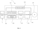
- FIG. 2 is a block diagram of a power-off protection circuit of a power tool according to an example of the present application.
- a power tool 1 includes a power terminal 110, a detection module 120, a controller 130, and a motor 140.
- the motor 140 may be a brushless motor.
- the power terminal 110 is configured to be electrically connected to a battery pack 2 to access a power supply of the battery pack 2.
- a circuit between the power terminal 110 and the battery pack 2 is a first circuit 101, and a circuit between the power terminal 110 and the motor 140 is a second circuit 102.
- the detection module 120 can detect that the first circuit 101 and the second circuit 102 are in a power-on mode or a power-off mode.
- the controller 130 can control the second circuit 102 to be in the power-on mode or the power-off mode.
- the power supply of the battery pack 2 can be supplied to the power tool 1, that is, the battery pack 2 is in good contact with an electrical connection structure of the power tool 1.
- the first circuit 101 is in the power-off mode, that is, the battery pack 2 is not electrically connected to the power tool 1, for example, the battery pack 2 is separated from the power tool 1, the power supply of the battery pack 2 cannot be supplied to the power tool 1.
- the battery pack 2 is plugged into the power tool 1, where the first circuit 101 is in the power-on mode when the battery pack 2 is plugged into the power tool 1, and the first circuit 101 is in the power-off mode when the battery pack 2 is pulled out of the power tool 1.
- a power supply received by the power terminal 110 from the battery pack 2 can be delivered to the motor 140 so that the motor 140 can rotate.
- the power supply received by the power terminal 110 from the battery pack 2 cannot be delivered to the motor 140 so that the motor 140 stops rotating or keeps still.
- the power tool 1 further includes an operation switch 150 disposed between the power terminal 110 and the motor 140.
- the operation switch 150 can control the second circuit 102 to be in the power-off mode or control, through the controller 130, the second circuit 102 to be in the power-on mode.
- the operation switch 150 can be moved between a first position and a second position. When the operation switch 150 is at the first position, the operation switch 150 is in the off state, and when the operation switch 150 is at the second position, the operation switch 150 is in the on state. When the operation switch 150 is in the off state, the second circuit 102 is in the power-off mode. When the operation switch 150 is in the on state, the controller 130 can control the second circuit 102 to be in the power-on mode.
- the operation switch 150 can directly control whether the second circuit 102 is in the power-on mode, a relatively high security risk is caused.
- the operation of safely replacing the battery pack 2 should be as follows: the operation switch 150 is turned off so that the second circuit 102 is in the power-off mode, next, the battery pack 2 is pulled out so that the first circuit 101 is in the power-off mode, then another battery pack 2 is plugged so that the first circuit 101 is restored to the power-on mode but the operation switch 150 is kept in the off state so that the second circuit 102 is in the power-off mode, and when a user needs to work by using the power tool 1, the operation switch 150 is turned on so that the second circuit 102 is switched from the power-off mode to the power-on mode.
- the user may replace the battery pack 2 in violation of regulations: when the operation switch 150 is in the on state, the battery pack 2 is directly pulled out and then another battery pack 2 is plugged.
- the second circuit 102 is always in the power-on mode, and when the first circuit 101 is restored to the power-on mode, the power supply of the battery pack 2 can be quickly delivered to the motor 140 through the first circuit 101 and the second circuit 102 so that the motor 140 in a coast state is driven to rotate again (after the power supply is stopped, the motor 140 does not stop rotating immediately but coasts for a period of time under the action of inertia).
- Power tools such as the miter saw or the angle grinder have relatively high inertia.
- the motor 140 of this type of power tool 1 coasts for a relatively long time after the power-off. If the operation switch 150 is kept in the on state when the user replaces the battery pack 2 of the miter saw, the motor 140 of the miter saw into which the battery pack 2 is plugged again is started in the coast state, and a saw blade is driven to rotate quickly and may hurt an unprepared person near the miter saw.
- the present application provides an example.
- the controller 130 controls the second circuit 102 to be in the power-off mode within a first preset time.
- the first preset time may be greater than or equal to a coast time of the motor 140.
- the first preset time may be 2 seconds, 5 seconds, or 10 seconds.
- the controller 130 controls the second circuit 102 to be in the power-off mode within the first preset time so that the case is avoided where the motor 140 is powered on again immediately after the power-off so as to drive a working accessory to rotate quickly.
- the security risk of the power tool 1 is reduced.
- the controller 130 even if the detection module 120 detects, within the first preset time, that the first circuit 101 is switched from the power-off mode to the power-on mode, the controller 130 still controls the second circuit 102 to be in the power-off mode within the first preset time.
- the controller 130 controls the second circuit 102 to be in the power-on mode only when the detection module 120 detects, outside the first preset time, that the first circuit 101 is in the power-on mode.
- the operation switch 150 is configured to be incapable of directly controlling the second circuit 102 to be switched from the power-off mode to the power-on mode, and the operation switch 150 needs to control, through the controller 130, the second circuit 102 to be switched to the power-on mode.
- the controller 130 controls the second circuit 102 to be in the power-off mode within the first preset time. Even if the operation switch 150 is always in the on state within the first preset time or is switched from the off state to the on state, the controller 130 still controls the second circuit 102 to be in the power-off mode within the first preset time.
- the controller 130 controls the second circuit 102 to be in the power-on mode only when the detection module 120 detects, outside the first preset time, that the first circuit 101 is in the power-on mode and the operation switch 150 is in the on state outside the first preset time.
- the power tool 1 further includes a communication terminal 160, and the communication terminal 160 performs data communication with the battery pack 2.
- the detection module 130 can assist in determining, by detecting whether the level of the communication terminal 160 varies, whether the battery pack 2 is not electrically connected to the power tool 1, that is, the detection module 130 can determine, based on whether the level of the communication terminal 160 varies, that the first circuit 101 is in the power-on mode or the power-off mode.
- the detection module 130 can assist in determining, by detecting the magnitude of the phase current of the motor, whether the battery pack 2 is not electrically connected to the power tool 1, that is, the detection module 130 can determine, based on the magnitude of the phase current of the motor 140, that the first circuit 101 is in the power-on mode or the power-off mode.
- the present application provides an example in which it can be determined, in a relatively accurate manner, whether the first circuit 101 is switched from the power-on mode to the power-off mode.
- the detection module 120 can detect whether the level of the communication terminal 160 varies, and the detection module 120 can further detect the phase current of the motor 140. When the absolute value of the phase current of the motor 140 is less than a preset current threshold and the level of the communication terminal 160 does not vary within a second preset time, the detection module 120 determines that the first circuit 101 is in the power-off mode.
- the present application further provides an example in which it can be determined whether the first circuit 101 is switched from the power-on mode to the power-off mode.
- the detection module 120 can detect the back electromotive force of the motor 140 and the bus voltage of the motor 140. When the difference between the back electromotive force of the motor 140 and the bus voltage of the motor 140 is less than a preset voltage threshold within a third preset time, the detection module 120 determines that the first circuit 101 is in the power-off mode.
- the product of a current of the unloaded motor 140 and an internal resistance of the motor 140 may be calculated and used as a basis for a value range of the preset voltage threshold.
- the present application further provides another example.
- the controller 30 controls the second circuit 102 based on a time when the first circuit 101 is in the power-off mode before the mode switchover. If the time when the first circuit 101 is in the power-off mode before the mode switchover does not exceed the first preset time, the second circuit 102 is controlled to be in the power-off mode.
- the first preset time may be greater than or equal to 2 seconds and less than or equal to 10 seconds.
- the controller 30 may control the second circuit 102 to be in the power-on mode if the time when the first circuit 101 is in the power-off mode before the mode switchover has exceeded the first preset time.
- the operation switch 150 is configured to be incapable of directly controlling the second circuit 102 to be switched from the power-off mode to the power-on mode, and the operation switch 150 needs to control, through the controller 130, the second circuit 102 to be switched to the power-on mode.
- the controller 30 controls the second circuit 102 to be in the power-off mode if the operation switch 150 is in the on mode and the time when the first circuit 101 is in the power-off mode before the mode switchover does not exceed the first preset time.
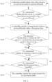
- the present application further provides a power-off protection method applicable to the power tool 1 such as the miter saw.
- the power tool 1 includes the motor 140, the power terminal 110, the detection module 120, the controller 130, and the operation switch 150 as mentioned in the preceding example.
- the power-off protection method includes the steps below.
- the detection module 120 detects that the first circuit 101 is in the power-on mode or the power-off mode.
- step S120 it is determined whether the first circuit 101 is switched from the power-on mode to the power-off mode. If yes, step S130 is performed. If not, the detection is continued.
- the controller 140 controls the second circuit 102 to be in the power-off mode within the first preset time.
- step S140 the detection module 120 detects whether the first circuit 101 is switched from the power-off mode to the power-on mode. If yes, step S150 is performed. If not, step S130 is performed.
- step S150 it is determined whether the operation switch is in the on state. If yes, step S160 is performed. If not, it is continuously detected whether the operation switch is in the on state.
- step S160 it is determined whether the first preset time is exceeded. If yes, step S170 is performed. If not, it is continuously detected whether the first preset time is exceeded.
- the controller 140 controls the second circuit 102 to be in the power-on mode.
- the preceding power-off protection method improves the security performance of the power tool 1.
Landscapes
- Engineering & Computer Science (AREA)
- Mechanical Engineering (AREA)
- Life Sciences & Earth Sciences (AREA)
- Wood Science & Technology (AREA)
- Forests & Forestry (AREA)
- Charge And Discharge Circuits For Batteries Or The Like (AREA)
- Protection Of Static Devices (AREA)
Abstract
Description
- The present application relates to the field of electronic technologies and, in particular, to a power tool.
- Power tools such as a miter saw or an angle grinder have relatively high inertia. Therefore, the motor of this type of power tool coasts for a relatively long time after power-off. If a user turns on a switch and the power tool is powered again during the coast time of the motor after the power-off, the power tool may be caused to run again, thus causing a great security risk to an unprepared person near the power tool.
- This part provides background information related to the present application, which is not necessarily the existing art.
- The present application aims to solve or at least alleviate all or part of the preceding problems. Therefore, an object of the present application is to provide a power tool and a power-off protection method thereof.
- To achieve the preceding object, the present application adopts the technical solutions described below.
- A power tool includes a motor, a power terminal, a detection module, and a controller. The power terminal is configured to access a power supply of a battery pack. The detection module is capable of detecting that a first circuit between the power terminal and the battery pack is in a power-on mode or a power-off mode. The controller is capable of controlling a second circuit between the power terminal and the motor to be in a power-on mode or a power-off mode. The controller is configured to, when the detection module detects that the first circuit is switched from the power-on mode to the power-off mode, control the second circuit to be in the power-off mode within a first preset time.
- In some examples, the controller is configured to, when the detection module detects, within the first preset time, that the first circuit is in the power-on mode again, control the second circuit to be in the power-off mode within the first preset time.
- In some examples, the controller is configured to, when the detection module detects, outside the first preset time, that the first circuit is in the power-on mode, control the second circuit to be in the power-on mode.
- In some examples, the power tool further includes an operation switch capable of controlling the second circuit to be in the power-on mode or the power-off mode, where the controller controls the second circuit to be in the power-off mode when the operation switch is in the off state.
- In some examples, the power tool further includes an operation switch capable of controlling the second circuit to be in the power-on mode or the power-off mode, where the second circuit is in the power-off mode when the operation switch is in the off state, and the controller controls the second circuit to be in the power-on mode or the power-off mode when the operation switch is in the on state.
- In some examples, the controller is configured to, when the operation switch is in the on state within the first preset time and the detection module detects, within the first preset time, that the first circuit is in the power-on mode again, control the second circuit to be in the power-off mode within the first preset time.
- In some examples, the controller is configured to, when the operation switch is in the on state outside the first preset time and the detection module detects, outside the first preset time, that the first circuit is in the power-on mode, control the second circuit to be in the power-on mode.
- In some examples, the controller is configured to, when the operation switch is switched from the off state to the on state within the first preset time and the detection module detects, within the first preset time, that the first circuit is in the power-on mode again, control the second circuit to be in the power-off mode within the first preset time.
- In some examples, the power tool further includes a communication terminal configured to perform data communication with the battery pack, where the detection module is capable of detecting whether a level of the communication terminal varies.
- In some examples, the detection module determines, based on whether the level of the communication terminal varies, that the first circuit is in the power-on mode or the power-off mode.
- In some examples, the detection module is also capable of detecting a phase current of the motor and determining, based on the magnitude of the phase current of the motor, that the first circuit is in the power-on mode or the power-off mode.
- In some examples, the detection module is also capable of detecting a phase current of the motor. The detection module is configured to, when the absolute value of the phase current of the motor is less than a preset current threshold and the level of the communication terminal does not vary within a second preset time, determine that the first circuit is in the power-off mode.
- In some examples, the detection module is also capable of detecting a back electromotive force of the motor and a bus voltage of the motor. The detection module is configured to, when the difference between the back electromotive force of the motor and the bus voltage of the motor is less than a preset voltage threshold within a third preset time, determine that the first circuit is in the power-off mode.
- In some examples, the battery pack is plugged into the power tool, where the first circuit is in the power-on mode when the battery pack is plugged into the power tool, and the first circuit is in the power-off mode when the battery pack is pulled out of the power tool.
- In some examples, the first preset time is greater than or equal to a coast time of the motor.
- A power tool includes: a motor; a power terminal configured to access a power supply of a battery pack; a detection module capable of detecting that a first circuit between the power terminal and the battery pack is in a power-on mode or a power-off mode; and a controller capable of controlling a second circuit between the power terminal and the motor to be in a power-on mode or a power-off mode. The controller is configured to, when the detection module detects that the first circuit is switched from the power-off mode to the power-on mode, control the second circuit to be in the power-off mode if a time when the first circuit is in the power-off mode before the switchover does not exceed a first preset time.
- In some examples, the first preset time is greater than or equal to 2 seconds and less than or equal to 10 seconds.
- In some examples, the controller is configured to, when the detection module detects that the first circuit is switched from the power-off mode to the power-on mode, control the second circuit to be in the power-on mode if a time when the first circuit is in the power-off mode before the switchover exceeds the first preset time.
- In some examples, the power tool further includes an operation switch, where the controller is configured to, when the detection module detects that the first circuit is switched from the power-off mode to the power-on mode, control the second circuit to be in the power-off mode if the operation switch is in the on state and a time when the first circuit is in the power-off mode before the switchover does not exceed the first preset time.
- A power-off protection method of a power tool is provided, where the power tool includes a motor, a power terminal, a detection module, and a controller. The power terminal is configured to access a power supply of a battery pack. The detection module is capable of detecting that a first circuit between the power terminal and the battery pack is in a power-on mode or a power-off mode. The controller is capable of controlling a second circuit between the power terminal and the motor to be in a power-on mode or a power-off mode. The power-off protection method includes the step: when the detection module detects that the first circuit is switched from the power-on mode to the power-off mode, the controller controls the second circuit to be in the power-off mode within a first preset time.
- The present application has the following benefit: the power-off protection method provided by the present application improves the security performance of the power tool.
-
-
FIG. 1 is a perspective view of a power tool according to an example of the present application; -
FIG. 2 is a block diagram of a power-off protection circuit of a power tool according to an example of the present application; and -
FIG. 3 is a flowchart of a power-off protection method of a power tool according to an example of the present application. - Before any examples of this application are explained in detail, it is to be understood that this application is not limited to its application to the structural details and the arrangement of components set forth in the following description or illustrated in the above drawings.
- In this application, the terms "comprising", "including", "having" or any other variation thereof are intended to cover an inclusive inclusion such that a process, method, article or device comprising a series of elements includes not only those series of elements, but also other elements not expressly listed, or elements inherent in the process, method, article, or device. Without further limitations, an element defined by the phrase "comprising a ..." does not preclude the presence of additional identical elements in the process, method, article, or device comprising that element.
- In this application, the term "and/or" is a kind of association relationship describing the relationship between associated objects, which means that there can be three kinds of relationships. For example, A and/or B can indicate that A exists alone, A and B exist simultaneously, and B exists alone. In addition, the character "/" in this application generally indicates that the contextual associated objects belong to an "and/or" relationship.
- In this application, the terms "connection", "combination", "coupling" and "installation" may be direct connection, combination, coupling or installation, and may also be indirect connection, combination, coupling or installation. Among them, for example, direct connection means that two members or assemblies are connected together without intermediaries, and indirect connection means that two members or assemblies are respectively connected with at least one intermediate members and the two members or assemblies are connected by the at least one intermediate members. In addition, "connection" and "coupling" are not limited to physical or mechanical connections or couplings, and may include electrical connections or couplings.
- In this application, it is to be understood by those skilled in the art that a relative term (such as "about", "approximately", and "substantially") used in conjunction with quantity or condition includes a stated value and has a meaning dictated by the context. For example, the relative term includes at least a degree of error associated with the measurement of a particular value, a tolerance caused by manufacturing, assembly, and use associated with the particular value, and the like. Such relative term should also be considered as disclosing the range defined by the absolute values of the two endpoints. The relative term may refer to plus or minus of a certain percentage (such as 1%, 5%, 10%, or more) of an indicated value. A value that did not use the relative term should also be disclosed as a particular value with a tolerance. In addition, "substantially" when expressing a relative angular position relationship (for example, substantially parallel, substantially perpendicular), may refer to adding or subtracting a certain degree (such as 1 degree, 5 degrees, 10 degrees or more) to the indicated angle.
- In this application, those skilled in the art will understand that a function performed by an assembly may be performed by one assembly, multiple assemblies, one member, or multiple members. Likewise, a function performed by a member may be performed by one member, an assembly, or a combination of members.
- In this application, the terms "up", "down", "left", "right", "front", and "rear" " and other directional words are described based on the orientation or positional relationship shown in the drawings, and should not be understood as limitations to the examples of this application. In addition, in this context, it also needs to be understood that when it is mentioned that an element is connected "above" or "under" another element, it can not only be directly connected "above" or "under" the other element, but can also be indirectly connected "above" or "under" the other element through an intermediate element. It should also be understood that orientation words such as upper side, lower side, left side, right side, front side, and rear side do not only represent perfect orientations, but can also be understood as lateral orientations. For example, lower side may include directly below, bottom left, bottom right, front bottom, and rear bottom.
- In this application, the terms "controller", "processor", "central processor", "CPU" and "MCU" are interchangeable. Where a unit "controller", "processor", "central processing", "CPU", or "MCU" is used to perform a specific function, the specific function may be implemented by a single aforementioned unit or a plurality of the aforementioned unit.
- In this application, the term "device", "module" or "unit" may be implemented in the form of hardware or software to achieve specific functions.
- In this application, the terms "computing", "judging", "controlling", "determining", "recognizing" and the like refer to the operations and processes of a computer system or similar electronic computing device (e.g., controller, processor, etc.).
-
FIG. 1 shows a power tool according to an example of the present application, where the power tool is a miter saw. It is to be understood by those skilled in the art that the power tool provided by the present application is not limited to the miter saw and may be a table saw, an angle grinder, an electric drill, a chain saw, a string trimmer, or the like. -
FIG. 2 is a block diagram of a power-off protection circuit of a power tool according to an example of the present application. Referring toFIG. 2 , apower tool 1 includes apower terminal 110, adetection module 120, acontroller 130, and amotor 140. Themotor 140 may be a brushless motor. Thepower terminal 110 is configured to be electrically connected to abattery pack 2 to access a power supply of thebattery pack 2. A circuit between thepower terminal 110 and thebattery pack 2 is afirst circuit 101, and a circuit between thepower terminal 110 and themotor 140 is asecond circuit 102. - The
detection module 120 can detect that thefirst circuit 101 and thesecond circuit 102 are in a power-on mode or a power-off mode. Thecontroller 130 can control thesecond circuit 102 to be in the power-on mode or the power-off mode. - When the
first circuit 101 is in the power-on mode, the power supply of thebattery pack 2 can be supplied to thepower tool 1, that is, thebattery pack 2 is in good contact with an electrical connection structure of thepower tool 1. When thefirst circuit 101 is in the power-off mode, that is, thebattery pack 2 is not electrically connected to thepower tool 1, for example, thebattery pack 2 is separated from thepower tool 1, the power supply of thebattery pack 2 cannot be supplied to thepower tool 1. In some examples, thebattery pack 2 is plugged into thepower tool 1, where thefirst circuit 101 is in the power-on mode when thebattery pack 2 is plugged into thepower tool 1, and thefirst circuit 101 is in the power-off mode when thebattery pack 2 is pulled out of thepower tool 1. - When the
second circuit 102 is in the power-on mode, a power supply received by thepower terminal 110 from thebattery pack 2 can be delivered to themotor 140 so that themotor 140 can rotate. When thesecond circuit 102 is in the power-off mode, the power supply received by thepower terminal 110 from thebattery pack 2 cannot be delivered to themotor 140 so that themotor 140 stops rotating or keeps still. - The
power tool 1 further includes anoperation switch 150 disposed between thepower terminal 110 and themotor 140. Theoperation switch 150 can control thesecond circuit 102 to be in the power-off mode or control, through thecontroller 130, thesecond circuit 102 to be in the power-on mode. In some examples, theoperation switch 150 can be moved between a first position and a second position. When theoperation switch 150 is at the first position, theoperation switch 150 is in the off state, and when theoperation switch 150 is at the second position, theoperation switch 150 is in the on state. When theoperation switch 150 is in the off state, thesecond circuit 102 is in the power-off mode. When theoperation switch 150 is in the on state, thecontroller 130 can control thesecond circuit 102 to be in the power-on mode. - In some examples, if the
operation switch 150 can directly control whether thesecond circuit 102 is in the power-on mode, a relatively high security risk is caused. For example, the operation of safely replacing thebattery pack 2 should be as follows: theoperation switch 150 is turned off so that thesecond circuit 102 is in the power-off mode, next, thebattery pack 2 is pulled out so that thefirst circuit 101 is in the power-off mode, then anotherbattery pack 2 is plugged so that thefirst circuit 101 is restored to the power-on mode but theoperation switch 150 is kept in the off state so that thesecond circuit 102 is in the power-off mode, and when a user needs to work by using thepower tool 1, theoperation switch 150 is turned on so that thesecond circuit 102 is switched from the power-off mode to the power-on mode. In some scenarios, the user may replace thebattery pack 2 in violation of regulations: when theoperation switch 150 is in the on state, thebattery pack 2 is directly pulled out and then anotherbattery pack 2 is plugged. In the replacement process, thesecond circuit 102 is always in the power-on mode, and when thefirst circuit 101 is restored to the power-on mode, the power supply of thebattery pack 2 can be quickly delivered to themotor 140 through thefirst circuit 101 and thesecond circuit 102 so that themotor 140 in a coast state is driven to rotate again (after the power supply is stopped, themotor 140 does not stop rotating immediately but coasts for a period of time under the action of inertia). Power tools such as the miter saw or the angle grinder have relatively high inertia. Therefore, themotor 140 of this type ofpower tool 1 coasts for a relatively long time after the power-off. If theoperation switch 150 is kept in the on state when the user replaces thebattery pack 2 of the miter saw, themotor 140 of the miter saw into which thebattery pack 2 is plugged again is started in the coast state, and a saw blade is driven to rotate quickly and may hurt an unprepared person near the miter saw. - To resolve the preceding security risk, the present application provides an example. In this example, when the
detection module 120 detects that thefirst circuit 101 is switched from the power-on mode to the power-off mode, thecontroller 130 controls thesecond circuit 102 to be in the power-off mode within a first preset time. Optionally, the first preset time may be greater than or equal to a coast time of themotor 140. Specifically, the first preset time may be 2 seconds, 5 seconds, or 10 seconds. - In this example, after the
battery pack 2 is pulled out of thepower tool 1, thecontroller 130 controls thesecond circuit 102 to be in the power-off mode within the first preset time so that the case is avoided where themotor 140 is powered on again immediately after the power-off so as to drive a working accessory to rotate quickly. Thus, the security risk of thepower tool 1 is reduced. - In this example, even if the
detection module 120 detects, within the first preset time, that thefirst circuit 101 is switched from the power-off mode to the power-on mode, thecontroller 130 still controls thesecond circuit 102 to be in the power-off mode within the first preset time. Thecontroller 130 controls thesecond circuit 102 to be in the power-on mode only when thedetection module 120 detects, outside the first preset time, that thefirst circuit 101 is in the power-on mode. - In some examples, the
operation switch 150 is configured to be incapable of directly controlling thesecond circuit 102 to be switched from the power-off mode to the power-on mode, and theoperation switch 150 needs to control, through thecontroller 130, thesecond circuit 102 to be switched to the power-on mode. For example, after thebattery pack 2 is pulled out of thepower tool 1, thecontroller 130 controls thesecond circuit 102 to be in the power-off mode within the first preset time. Even if theoperation switch 150 is always in the on state within the first preset time or is switched from the off state to the on state, thecontroller 130 still controls thesecond circuit 102 to be in the power-off mode within the first preset time. Thecontroller 130 controls thesecond circuit 102 to be in the power-on mode only when thedetection module 120 detects, outside the first preset time, that thefirst circuit 101 is in the power-on mode and theoperation switch 150 is in the on state outside the first preset time. - The
power tool 1 further includes acommunication terminal 160, and thecommunication terminal 160 performs data communication with thebattery pack 2. When thebattery pack 2 is pulled out of thepower tool 1, thefirst circuit 101 is switched from the power-on mode to the power-off mode, no data communication occurs between thecommunication terminal 160 and thebattery pack 2, and a level of thecommunication terminal 160 keeps stable. Therefore, thedetection module 130 can assist in determining, by detecting whether the level of thecommunication terminal 160 varies, whether thebattery pack 2 is not electrically connected to thepower tool 1, that is, thedetection module 130 can determine, based on whether the level of thecommunication terminal 160 varies, that thefirst circuit 101 is in the power-on mode or the power-off mode. - After the
battery pack 2 is pulled out of thepower tool 1, thefirst circuit 101 is switched from the power-on mode to the power-off mode. However, themotor 140 does not immediately stop rotating. Instead, themotor 140 coasts for a period of time under the action of the inertia. Themotor 140 generates a back electromotive force in the coast state. Therefore, a small current is generated. Therefore, thedetection module 130 can assist in determining, by detecting the magnitude of the phase current of the motor, whether thebattery pack 2 is not electrically connected to thepower tool 1, that is, thedetection module 130 can determine, based on the magnitude of the phase current of themotor 140, that thefirst circuit 101 is in the power-on mode or the power-off mode. - In summary, the present application provides an example in which it can be determined, in a relatively accurate manner, whether the
first circuit 101 is switched from the power-on mode to the power-off mode. In this example, thedetection module 120 can detect whether the level of thecommunication terminal 160 varies, and thedetection module 120 can further detect the phase current of themotor 140. When the absolute value of the phase current of themotor 140 is less than a preset current threshold and the level of thecommunication terminal 160 does not vary within a second preset time, thedetection module 120 determines that thefirst circuit 101 is in the power-off mode. - The present application further provides an example in which it can be determined whether the
first circuit 101 is switched from the power-on mode to the power-off mode. Thedetection module 120 can detect the back electromotive force of themotor 140 and the bus voltage of themotor 140. When the difference between the back electromotive force of themotor 140 and the bus voltage of themotor 140 is less than a preset voltage threshold within a third preset time, thedetection module 120 determines that thefirst circuit 101 is in the power-off mode. In some examples, the product of a current of the unloadedmotor 140 and an internal resistance of themotor 140 may be calculated and used as a basis for a value range of the preset voltage threshold. - To resolve the security risk mentioned above, the present application further provides another example. In this example, when the
detection module 120 detects that thefirst circuit 101 is switched from the power-off mode to the power-on mode, the controller 30 controls thesecond circuit 102 based on a time when thefirst circuit 101 is in the power-off mode before the mode switchover. If the time when thefirst circuit 101 is in the power-off mode before the mode switchover does not exceed the first preset time, thesecond circuit 102 is controlled to be in the power-off mode. Optionally, the first preset time may be greater than or equal to 2 seconds and less than or equal to 10 seconds. - In some examples, if the time when the
first circuit 101 is in the power-off mode before the mode switchover has exceeded the first preset time, the controller 30 may control thesecond circuit 102 to be in the power-on mode. - In some examples, the
operation switch 150 is configured to be incapable of directly controlling thesecond circuit 102 to be switched from the power-off mode to the power-on mode, and theoperation switch 150 needs to control, through thecontroller 130, thesecond circuit 102 to be switched to the power-on mode. When thedetection module 120 detects that thefirst circuit 101 is switched from the power-off mode to the power-on mode, the controller 30 controls thesecond circuit 102 to be in the power-off mode if theoperation switch 150 is in the on mode and the time when thefirst circuit 101 is in the power-off mode before the mode switchover does not exceed the first preset time. - As shown in
FIG. 3 , the present application further provides a power-off protection method applicable to thepower tool 1 such as the miter saw. Thepower tool 1 includes themotor 140, thepower terminal 110, thedetection module 120, thecontroller 130, and theoperation switch 150 as mentioned in the preceding example. The power-off protection method includes the steps below. - In S110, the
detection module 120 detects that thefirst circuit 101 is in the power-on mode or the power-off mode. - In S120, it is determined whether the
first circuit 101 is switched from the power-on mode to the power-off mode. If yes, step S130 is performed. If not, the detection is continued. - In S130, the
controller 140 controls thesecond circuit 102 to be in the power-off mode within the first preset time. - In S140, the
detection module 120 detects whether thefirst circuit 101 is switched from the power-off mode to the power-on mode. If yes, step S150 is performed. If not, step S130 is performed. - In S150, it is determined whether the operation switch is in the on state. If yes, step S160 is performed. If not, it is continuously detected whether the operation switch is in the on state.
- In S160, it is determined whether the first preset time is exceeded. If yes, step S170 is performed. If not, it is continuously detected whether the first preset time is exceeded.
- In S170, the
controller 140 controls thesecond circuit 102 to be in the power-on mode. - The preceding power-off protection method improves the security performance of the
power tool 1. - The basic principles, main features, and advantages of this application are shown and described above. It is to be understood by those skilled in the art that the aforementioned examples do not limit the present application in any form, and all technical solutions obtained through equivalent substitutions or equivalent transformations fall within the scope of the present application.
Claims (15)
- A power tool (1), comprising:a motor (120);a power terminal (110) configured to access a power supply of a battery pack (2);a detection module (120) capable of detecting that a first circuit (101) between the power terminal and the battery pack is in a power-on mode or a power-off mode; anda controller (130) capable of controlling a second circuit (102) between the power terminal and the motor to be in a power-on mode or a power-off mode;wherein the controller is configured to, when the detection module detects that the first circuit is switched from the power-on mode to the power-off mode, control the second circuit to be in the power-off mode within a first preset time.
- The power tool according to claim 1, wherein the controller is configured to, when the detection module detects, within the first preset time, that the first circuit is in the power-on mode again, control the second circuit to be in the power-off mode within the first preset time.
- The power tool according to claim 2, wherein the controller is configured to, when the detection module detects, outside the first preset time, that the first circuit is in the power-on mode, control the second circuit to be in the power-on mode.
- The power tool according to claim 1, further comprising an operation switch (150) capable of controlling the second circuit to be in the power-on mode or the power-off mode, wherein the controller controls the second circuit to be in the power-off mode when the operation switch is in an off state.
- The power tool according to claim 1, further comprising an operation switch (150) capable of controlling the second circuit to be in the power-on mode or the power-off mode, wherein the second circuit is in the power-off mode when the operation switch is in an off state, and the controller controls the second circuit to be in the power-on mode or the power-off mode when the operation switch is in an on state.
- The power tool according to claim 4 or 5, wherein the controller is configured to, when the operation switch is in the on state within the first preset time and the detection module detects, within the first preset time, that the first circuit is in the power-on mode again, control the second circuit to be in the power-off mode within the first preset time.
- The power tool according to claim 6, wherein the controller is configured to, when the operation switch is in the on state outside the first preset time and the detection module detects, outside the first preset time, that the first circuit is in the power-on mode, control the second circuit to be in the power-on mode.
- The power tool according to claim 4 or 5, wherein the controller is configured to, when the operation switch is switched from the off state to the on state within the first preset time and the detection module detects, within the first preset time, that the first circuit is in the power-on mode again, control the second circuit to be in the power-off mode within the first preset time.
- The power tool according to claim 1, further comprising a communication terminal (160) configured to perform data communication with the battery pack, wherein the detection module is capable of detecting whether a level of the communication terminal varies.
- The power tool according to claim 9, wherein the detection module determines, based on whether the level of the communication terminal varies, that the first circuit is in the power-on mode or the power-off mode.
- The power tool according to claim 10, wherein the detection module is also capable of detecting a phase current of the motor and determining, based on a magnitude of the phase current of the motor, that the first circuit is in the power-on mode or the power-off mode.
- The power tool according to claim 9, wherein the detection module is also capable of detecting a phase current of the motor and is configured to, when an absolute value of the phase current of the motor is less than a preset current threshold and the level of the communication terminal does not vary within a second preset time, determine that the first circuit is in the power-off mode.
- The power tool according to claim 1, wherein the detection module is also capable of detecting a back electromotive force of the motor and a bus voltage of the motor and is configured to, when a difference between the back electromotive force of the motor and the bus voltage of the motor is less than a preset voltage threshold within a third preset time, determine that the first circuit is in the power-off mode.
- The power tool according to claim 1, wherein the battery pack is plugged to the power tool, the first circuit is in the power-on mode when the battery pack is plugged to the power tool, and the first circuit is in the power-off mode when the battery pack is pulled out of the power tool.
- The power tool according to claim 1, wherein the first preset time is greater than or equal to a coast time of the motor.
Applications Claiming Priority (1)
| Application Number | Priority Date | Filing Date | Title |
|---|---|---|---|
| CN202310323539.XA CN118739198A (en) | 2023-03-29 | 2023-03-29 | Electric tool and power-off protection method thereof |
Publications (2)
| Publication Number | Publication Date |
|---|---|
| EP4438233A1 true EP4438233A1 (en) | 2024-10-02 |
| EP4438233B1 EP4438233B1 (en) | 2025-07-30 |
Family
ID=89767403
Family Applications (1)
| Application Number | Title | Priority Date | Filing Date |
|---|---|---|---|
| EP24154304.0A Active EP4438233B1 (en) | 2023-03-29 | 2024-01-29 | Power tool |
Country Status (3)
| Country | Link |
|---|---|
| US (1) | US20240326189A1 (en) |
| EP (1) | EP4438233B1 (en) |
| CN (1) | CN118739198A (en) |
Citations (4)
| Publication number | Priority date | Publication date | Assignee | Title |
|---|---|---|---|---|
| EP3150338A1 (en) * | 2015-09-30 | 2017-04-05 | Johnson Electric S.A. | Electric tool, a motor assembly and motor drive system |
| US20170304976A1 (en) * | 2016-04-20 | 2017-10-26 | Makita Corporation | Electric working machine |
| US20210291400A1 (en) * | 2020-03-20 | 2021-09-23 | Andreas Stihl Ag & Co. Kg | Hand-Portable Garden, Forestry and/or Construction Processing Device and Method for Operating a Hand-Portable Garden, Forestry and/or Construction Processing Device |
| CN115580200A (en) * | 2021-07-06 | 2023-01-06 | 南京泉峰科技有限公司 | Electric tools and their drive control circuits |
Family Cites Families (3)
| Publication number | Priority date | Publication date | Assignee | Title |
|---|---|---|---|---|
| DE102010027981A1 (en) * | 2010-04-20 | 2011-10-20 | Robert Bosch Gmbh | angle |
| KR101843997B1 (en) * | 2011-07-14 | 2018-04-02 | 시티즌 도케이 가부시키가이샤 | Machine tool and drive regulation device for said machine tool |
| JP7567434B2 (en) * | 2020-12-17 | 2024-10-16 | オムロン株式会社 | Electric gripping tool, machining method using electric gripping tool, machining program |
-
2023
- 2023-03-29 CN CN202310323539.XA patent/CN118739198A/en active Pending
-
2024
- 2024-01-29 EP EP24154304.0A patent/EP4438233B1/en active Active
- 2024-02-05 US US18/432,765 patent/US20240326189A1/en active Pending
Patent Citations (4)
| Publication number | Priority date | Publication date | Assignee | Title |
|---|---|---|---|---|
| EP3150338A1 (en) * | 2015-09-30 | 2017-04-05 | Johnson Electric S.A. | Electric tool, a motor assembly and motor drive system |
| US20170304976A1 (en) * | 2016-04-20 | 2017-10-26 | Makita Corporation | Electric working machine |
| US20210291400A1 (en) * | 2020-03-20 | 2021-09-23 | Andreas Stihl Ag & Co. Kg | Hand-Portable Garden, Forestry and/or Construction Processing Device and Method for Operating a Hand-Portable Garden, Forestry and/or Construction Processing Device |
| CN115580200A (en) * | 2021-07-06 | 2023-01-06 | 南京泉峰科技有限公司 | Electric tools and their drive control circuits |
Also Published As
| Publication number | Publication date |
|---|---|
| US20240326189A1 (en) | 2024-10-03 |
| EP4438233B1 (en) | 2025-07-30 |
| CN118739198A (en) | 2024-10-01 |
Similar Documents
| Publication | Publication Date | Title |
|---|---|---|
| EP1571458B1 (en) | Battery-powered tool capable of detecting discharged battery pack | |
| US12062999B2 (en) | Method for controlling a rotational speed of an electric tool and electric tool | |
| US12558768B2 (en) | Automatic ramp load sense for power tools | |
| EP4438233B1 (en) | Power tool | |
| GB2436959A (en) | Electric machine tool and method for operating the latter | |
| US11926031B2 (en) | Electric work machine | |
| EP4539229A1 (en) | Battery pack | |
| US11522376B2 (en) | Charging system, battery pack, and charger | |
| EP4300811A1 (en) | Low voltage protective features in power tools | |
| AU2024278868A1 (en) | Power tool | |
| US20250300582A1 (en) | Power tool and control method thereof | |
| CN213521276U (en) | Safety control system of direct current brushless non-inductive motor for electric tool | |
| CN109782643B (en) | Control method for starting heat engine of electric tool | |
| US12362686B2 (en) | Easy hole start operation for drilling power tools | |
| US20250080023A1 (en) | Power tool | |
| CN116276824B (en) | Power tools and their control methods | |
| CN221390362U (en) | Electric tool | |
| EP4653145A1 (en) | Power tool | |
| CN120110227A (en) | Electric tool and control method thereof | |
| CN224196017U (en) | circular saw | |
| CN119260675A (en) | Electric tool and control method thereof | |
| CN222840148U (en) | Power Tools | |
| JPH0630597A (en) | Motor drive | |
| US20240359289A1 (en) | Grinder with loss of control detection | |
| CN118264158A (en) | Electric tool and control method thereof |
Legal Events
| Date | Code | Title | Description |
|---|---|---|---|
| PUAI | Public reference made under article 153(3) epc to a published international application that has entered the european phase |
Free format text: ORIGINAL CODE: 0009012 |
|
| STAA | Information on the status of an ep patent application or granted ep patent |
Free format text: STATUS: THE APPLICATION HAS BEEN PUBLISHED |
|
| AK | Designated contracting states |
Kind code of ref document: A1 Designated state(s): AL AT BE BG CH CY CZ DE DK EE ES FI FR GB GR HR HU IE IS IT LI LT LU LV MC ME MK MT NL NO PL PT RO RS SE SI SK SM TR |
|
| STAA | Information on the status of an ep patent application or granted ep patent |
Free format text: STATUS: REQUEST FOR EXAMINATION WAS MADE |
|
| 17P | Request for examination filed |
Effective date: 20250207 |
|
| GRAP | Despatch of communication of intention to grant a patent |
Free format text: ORIGINAL CODE: EPIDOSNIGR1 |
|
| STAA | Information on the status of an ep patent application or granted ep patent |
Free format text: STATUS: GRANT OF PATENT IS INTENDED |
|
| GRAS | Grant fee paid |
Free format text: ORIGINAL CODE: EPIDOSNIGR3 |
|
| INTG | Intention to grant announced |
Effective date: 20250512 |
|
| GRAA | (expected) grant |
Free format text: ORIGINAL CODE: 0009210 |
|
| STAA | Information on the status of an ep patent application or granted ep patent |
Free format text: STATUS: THE PATENT HAS BEEN GRANTED |
|
| AK | Designated contracting states |
Kind code of ref document: B1 Designated state(s): AL AT BE BG CH CY CZ DE DK EE ES FI FR GB GR HR HU IE IS IT LI LT LU LV MC ME MK MT NL NO PL PT RO RS SE SI SK SM TR |
|
| REG | Reference to a national code |
Ref country code: GB Ref legal event code: FG4D |
|
| REG | Reference to a national code |
Ref country code: CH Ref legal event code: EP |
|
| REG | Reference to a national code |
Ref country code: DE Ref legal event code: R096 Ref document number: 602024000343 Country of ref document: DE |
|
| REG | Reference to a national code |
Ref country code: IE Ref legal event code: FG4D |
|
| REG | Reference to a national code |
Ref country code: NL Ref legal event code: MP Effective date: 20250730 |
|
| REG | Reference to a national code |
Ref country code: AT Ref legal event code: MK05 Ref document number: 1818451 Country of ref document: AT Kind code of ref document: T Effective date: 20250730 |
|
| PG25 | Lapsed in a contracting state [announced via postgrant information from national office to epo] |
Ref country code: PT Free format text: LAPSE BECAUSE OF FAILURE TO SUBMIT A TRANSLATION OF THE DESCRIPTION OR TO PAY THE FEE WITHIN THE PRESCRIBED TIME-LIMIT Effective date: 20251202 |
|
| PG25 | Lapsed in a contracting state [announced via postgrant information from national office to epo] |
Ref country code: IS Free format text: LAPSE BECAUSE OF FAILURE TO SUBMIT A TRANSLATION OF THE DESCRIPTION OR TO PAY THE FEE WITHIN THE PRESCRIBED TIME-LIMIT Effective date: 20251130 |
|
| PG25 | Lapsed in a contracting state [announced via postgrant information from national office to epo] |
Ref country code: NO Free format text: LAPSE BECAUSE OF FAILURE TO SUBMIT A TRANSLATION OF THE DESCRIPTION OR TO PAY THE FEE WITHIN THE PRESCRIBED TIME-LIMIT Effective date: 20251030 |
|
| REG | Reference to a national code |
Ref country code: LT Ref legal event code: MG9D |
|
| PG25 | Lapsed in a contracting state [announced via postgrant information from national office to epo] |
Ref country code: AT Free format text: LAPSE BECAUSE OF FAILURE TO SUBMIT A TRANSLATION OF THE DESCRIPTION OR TO PAY THE FEE WITHIN THE PRESCRIBED TIME-LIMIT Effective date: 20250730 |
|
| PG25 | Lapsed in a contracting state [announced via postgrant information from national office to epo] |
Ref country code: FI Free format text: LAPSE BECAUSE OF FAILURE TO SUBMIT A TRANSLATION OF THE DESCRIPTION OR TO PAY THE FEE WITHIN THE PRESCRIBED TIME-LIMIT Effective date: 20250730 |
|
| PG25 | Lapsed in a contracting state [announced via postgrant information from national office to epo] |
Ref country code: HR Free format text: LAPSE BECAUSE OF FAILURE TO SUBMIT A TRANSLATION OF THE DESCRIPTION OR TO PAY THE FEE WITHIN THE PRESCRIBED TIME-LIMIT Effective date: 20250730 Ref country code: NL Free format text: LAPSE BECAUSE OF FAILURE TO SUBMIT A TRANSLATION OF THE DESCRIPTION OR TO PAY THE FEE WITHIN THE PRESCRIBED TIME-LIMIT Effective date: 20250730 |
|
| PGFP | Annual fee paid to national office [announced via postgrant information from national office to epo] |
Ref country code: FR Payment date: 20251128 Year of fee payment: 3 |
|
| PG25 | Lapsed in a contracting state [announced via postgrant information from national office to epo] |
Ref country code: GR Free format text: LAPSE BECAUSE OF FAILURE TO SUBMIT A TRANSLATION OF THE DESCRIPTION OR TO PAY THE FEE WITHIN THE PRESCRIBED TIME-LIMIT Effective date: 20251031 |
|
| PG25 | Lapsed in a contracting state [announced via postgrant information from national office to epo] |
Ref country code: SE Free format text: LAPSE BECAUSE OF FAILURE TO SUBMIT A TRANSLATION OF THE DESCRIPTION OR TO PAY THE FEE WITHIN THE PRESCRIBED TIME-LIMIT Effective date: 20250730 |
|
| PG25 | Lapsed in a contracting state [announced via postgrant information from national office to epo] |
Ref country code: LV Free format text: LAPSE BECAUSE OF FAILURE TO SUBMIT A TRANSLATION OF THE DESCRIPTION OR TO PAY THE FEE WITHIN THE PRESCRIBED TIME-LIMIT Effective date: 20250730 |
|
| PG25 | Lapsed in a contracting state [announced via postgrant information from national office to epo] |
Ref country code: BG Free format text: LAPSE BECAUSE OF FAILURE TO SUBMIT A TRANSLATION OF THE DESCRIPTION OR TO PAY THE FEE WITHIN THE PRESCRIBED TIME-LIMIT Effective date: 20250730 Ref country code: PL Free format text: LAPSE BECAUSE OF FAILURE TO SUBMIT A TRANSLATION OF THE DESCRIPTION OR TO PAY THE FEE WITHIN THE PRESCRIBED TIME-LIMIT Effective date: 20250730 |
|
| PG25 | Lapsed in a contracting state [announced via postgrant information from national office to epo] |
Ref country code: RS Free format text: LAPSE BECAUSE OF FAILURE TO SUBMIT A TRANSLATION OF THE DESCRIPTION OR TO PAY THE FEE WITHIN THE PRESCRIBED TIME-LIMIT Effective date: 20251030 |
|
| PG25 | Lapsed in a contracting state [announced via postgrant information from national office to epo] |
Ref country code: ES Free format text: LAPSE BECAUSE OF FAILURE TO SUBMIT A TRANSLATION OF THE DESCRIPTION OR TO PAY THE FEE WITHIN THE PRESCRIBED TIME-LIMIT Effective date: 20250730 |
|
| PG25 | Lapsed in a contracting state [announced via postgrant information from national office to epo] |
Ref country code: SM Free format text: LAPSE BECAUSE OF FAILURE TO SUBMIT A TRANSLATION OF THE DESCRIPTION OR TO PAY THE FEE WITHIN THE PRESCRIBED TIME-LIMIT Effective date: 20250730 |
|
| PG25 | Lapsed in a contracting state [announced via postgrant information from national office to epo] |
Ref country code: DK Free format text: LAPSE BECAUSE OF FAILURE TO SUBMIT A TRANSLATION OF THE DESCRIPTION OR TO PAY THE FEE WITHIN THE PRESCRIBED TIME-LIMIT Effective date: 20250730 |
|
| PGFP | Annual fee paid to national office [announced via postgrant information from national office to epo] |
Ref country code: DE Payment date: 20251203 Year of fee payment: 3 |
|
| PG25 | Lapsed in a contracting state [announced via postgrant information from national office to epo] |
Ref country code: IT Free format text: LAPSE BECAUSE OF FAILURE TO SUBMIT A TRANSLATION OF THE DESCRIPTION OR TO PAY THE FEE WITHIN THE PRESCRIBED TIME-LIMIT Effective date: 20250730 |
|
| PG25 | Lapsed in a contracting state [announced via postgrant information from national office to epo] |
Ref country code: CZ Free format text: LAPSE BECAUSE OF FAILURE TO SUBMIT A TRANSLATION OF THE DESCRIPTION OR TO PAY THE FEE WITHIN THE PRESCRIBED TIME-LIMIT Effective date: 20250730 |
|
| PG25 | Lapsed in a contracting state [announced via postgrant information from national office to epo] |
Ref country code: SK Free format text: LAPSE BECAUSE OF FAILURE TO SUBMIT A TRANSLATION OF THE DESCRIPTION OR TO PAY THE FEE WITHIN THE PRESCRIBED TIME-LIMIT Effective date: 20250730 Ref country code: EE Free format text: LAPSE BECAUSE OF FAILURE TO SUBMIT A TRANSLATION OF THE DESCRIPTION OR TO PAY THE FEE WITHIN THE PRESCRIBED TIME-LIMIT Effective date: 20250730 |
|
| REG | Reference to a national code |
Ref country code: DE Ref legal event code: R097 Ref document number: 602024000343 Country of ref document: DE |
|
| PLBE | No opposition filed within time limit |
Free format text: ORIGINAL CODE: 0009261 |
|
| STAA | Information on the status of an ep patent application or granted ep patent |
Free format text: STATUS: NO OPPOSITION FILED WITHIN TIME LIMIT |
|
| REG | Reference to a national code |
Ref country code: CH Ref legal event code: L10 Free format text: ST27 STATUS EVENT CODE: U-0-0-L10-L00 (AS PROVIDED BY THE NATIONAL OFFICE) Effective date: 20260611 |
|
| PG25 | Lapsed in a contracting state [announced via postgrant information from national office to epo] |
Ref country code: LT Free format text: LAPSE BECAUSE OF FAILURE TO SUBMIT A TRANSLATION OF THE DESCRIPTION OR TO PAY THE FEE WITHIN THE PRESCRIBED TIME-LIMIT Effective date: 20250730 |
|
| 26N | No opposition filed |
Effective date: 20260501 |