EP4438210A1 - Cutting insert and cutting tool - Google Patents
Cutting insert and cutting tool Download PDFInfo
- Publication number
- EP4438210A1 EP4438210A1 EP22898601.4A EP22898601A EP4438210A1 EP 4438210 A1 EP4438210 A1 EP 4438210A1 EP 22898601 A EP22898601 A EP 22898601A EP 4438210 A1 EP4438210 A1 EP 4438210A1
- Authority
- EP
- European Patent Office
- Prior art keywords
- cutting insert
- pedestal
- center line
- seating
- axial direction
- Prior art date
- Legal status (The legal status is an assumption and is not a legal conclusion. Google has not performed a legal analysis and makes no representation as to the accuracy of the status listed.)
- Pending
Links
Images


Classifications
-
- B—PERFORMING OPERATIONS; TRANSPORTING
- B23—MACHINE TOOLS; METAL-WORKING NOT OTHERWISE PROVIDED FOR
- B23B—TURNING; BORING
- B23B27/00—Tools for turning or boring machines; Tools of a similar kind in general; Accessories therefor
- B23B27/14—Cutting tools of which the bits or tips or cutting inserts are of special material
- B23B27/16—Cutting tools of which the bits or tips or cutting inserts are of special material with exchangeable cutting bits or cutting inserts, e.g. able to be clamped
- B23B27/1603—Cutting tools of which the bits or tips or cutting inserts are of special material with exchangeable cutting bits or cutting inserts, e.g. able to be clamped with specially shaped plate-like exchangeable cutting inserts, e.g. chip-breaking groove
- B23B27/1611—Cutting tools of which the bits or tips or cutting inserts are of special material with exchangeable cutting bits or cutting inserts, e.g. able to be clamped with specially shaped plate-like exchangeable cutting inserts, e.g. chip-breaking groove characterised by having a special shape
-
- B—PERFORMING OPERATIONS; TRANSPORTING
- B23—MACHINE TOOLS; METAL-WORKING NOT OTHERWISE PROVIDED FOR
- B23C—MILLING
- B23C5/00—Milling-cutters
- B23C5/16—Milling-cutters characterised by physical features other than shape
- B23C5/20—Milling-cutters characterised by physical features other than shape with removable cutter bits or teeth or cutting inserts
- B23C5/22—Securing arrangements for bits or teeth or cutting inserts
- B23C5/2204—Securing arrangements for bits or teeth or cutting inserts with cutting inserts clamped against the walls of the recess in the cutter body by a clamping member acting upon the wall of a hole in the insert
- B23C5/2208—Securing arrangements for bits or teeth or cutting inserts with cutting inserts clamped against the walls of the recess in the cutter body by a clamping member acting upon the wall of a hole in the insert for plate-like cutting inserts
- B23C5/2213—Securing arrangements for bits or teeth or cutting inserts with cutting inserts clamped against the walls of the recess in the cutter body by a clamping member acting upon the wall of a hole in the insert for plate-like cutting inserts having a special shape
-
- B—PERFORMING OPERATIONS; TRANSPORTING
- B23—MACHINE TOOLS; METAL-WORKING NOT OTHERWISE PROVIDED FOR
- B23C—MILLING
- B23C2200/00—Details of milling cutting inserts
- B23C2200/16—Supporting or bottom surfaces
-
- B—PERFORMING OPERATIONS; TRANSPORTING
- B23—MACHINE TOOLS; METAL-WORKING NOT OTHERWISE PROVIDED FOR
- B23C—MILLING
- B23C2210/00—Details of milling cutters
- B23C2210/16—Fixation of inserts or cutting bits in the tool
- B23C2210/168—Seats for cutting inserts, supports for replacable cutting bits
-
- B—PERFORMING OPERATIONS; TRANSPORTING
- B23—MACHINE TOOLS; METAL-WORKING NOT OTHERWISE PROVIDED FOR
- B23C—MILLING
- B23C5/00—Milling-cutters
- B23C5/02—Milling-cutters characterised by the shape of the cutter
- B23C5/10—Shank-type cutters, i.e. with an integral shaft
- B23C5/109—Shank-type cutters, i.e. with an integral shaft with removable cutting inserts
Definitions
- a powder mixture of a hard metal component and a binder is press-formed to prepare a green compact for a cutting insert, and the green compact for a cutting insert is sintered in a state of being placed on a sintering plate.
- a contact reaction inhibitor is applied to a carbon sintering plate, unevenness is formed on a portion (a lower surface on a seating surface side) of a cutting insert that comes into contact with a sintering plate due to adhesion of the contact reaction inhibitor or sintering reaction marks.
- an unstably clamped state is incurred when the cutting insert is mounted to a tool main body.
- the present invention has been made in view of such circumstances, and an object thereof is to provide a cutting insert and a cutting tool capable of, in a case of being applied to a single-sided cutting insert, achieving both cost reduction and securing flatness of a seating surface by eliminating a need for a grinding step for a lower surface including the seating surface.
- the present invention proposes the following means.
- a cutting insert is a cutting insert having a plate shape and having a center line, including: an upper surface that forms one surface of two surfaces facing each other in an axial direction along the center line; a lower surface that forms the other surface of the two surfaces facing each other; a side surface that connects the upper surface and the lower surface in the axial direction; and a mounting hole that passes through the cutting insert in the axial direction, in which the side surface extends obliquely inward in a radial direction perpendicular to the center line from the upper surface toward the lower surface in the axial direction, the lower surface includes a seating surface having a flat surface perpendicular to the center line, and a pedestal having a protruding portion protruding from an outer peripheral edge of the seating surface in a direction away from the upper surface in the axial direction beyond the seating surface, and a top portion of the protruding portion of the pedestal is perpendicular to the center line.
- a configuration may be adopted in which a ridge between the upper surface and the side surface is inclined with respect to the flat surface perpendicular to the center line at a portion that protrudes most in the axial direction.
- Patent Document 1 requires a portion parallel to the lower surface, and a shape of a second cutting edge 26 is determined by this protruding flat surface.
- the lower surface according to the aspect of the present invention, it is possible to design all cutting edges of the cutting insert without limitation of a polishing step. Accordingly, as a cutting tool in which a cutting insert is mounted to an insert mounting seat of a tool main body that rotates about an axis, it is possible to set an optimum axial rake angle in an axial direction and an optimum radial rake angle in a radial direction.
- the top portion of the protruding portion of the pedestal may be provided with a flat surface.
- a configuration may be adopted in which the top portion of the protruding portion of the pedestal has a ridge shape.
- the wider seating surface enables stable abutting on the insert mounting seat of the tool main body.
- a configuration may be adopted in which the pedestal is provided over an entire outer peripheral edge of the seating surface.
- a configuration may be adopted in which the pedestal is provided along a part of the outer peripheral edge of the seating surface.
- a cutting tool includes: a tool main body that is rotatable in a tool rotation direction about an axis of rotation and has an insert mounting seat to which the cutting insert is mounted, in which the insert mounting seat has a bottom surface on which the seating surface of the cutting insert abuts.
- the seating surface of the cutting insert abuts on the bottom surface of the insert mounting seat, so that the cutting insert is mounted to the tool main body. Since the flat surfaces abut on each other, the cutting insert can be mounted to the tool main body without rattling, and a stably clamped state can be secured.
- a cutting insert and a cutting tool capable of, in a case of being applied to a single-sided cutting insert, achieving both cost reduction and securing flatness of a seating surface by eliminating a need for a grinding step for a lower surface including the seating surface.
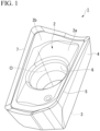
- FIG. 1 is a perspective view showing a cutting insert 1 according to a first embodiment of the present invention from a rake face side.
- FIGS. 2A to 2C are three views (a plan view and side views) showing the cutting insert 1 according to the first embodiment of the present invention.
- FIG. 3 is a perspective view showing the cutting insert 1 according to the first embodiment of the present invention from a seating surface side.
- the cutting insert 1 of the present embodiment is removably mounted to a tool main body that rotates about an axis, and performs cutting work on a work material made of a metal material, such as steel.
- the cutting insert 1 of the present embodiment shown in FIGS. 1 , 2A to 2C , and 3 is formed of a hard material such as cemented carbide.
- the cutting insert 1 is formed in a plate shape having a polygonal shape that is rotationally symmetrical with respect to a center line O in the plan view seen from the center line O extending in a thickness direction.
- the cutting insert 1 has a rectangular shape in the plan view, but is not limited to this shape.
- a direction along the center line O may be simply referred to as a thickness direction.
- a direction orthogonal to the center line O may be simply referred to as a radial direction.
- a circumferential direction about an axis centered on the center line O may be simply referred to as a circumferential direction.
- the cutting insert 1 includes a rake face (upper surface) 2 forming one surface of two surfaces facing each other in an axial direction along the center line O, a lower surface 3 forming the other surface of the two surfaces, side surfaces 4 that connects the rake face 2 to the lower surface 3, cutting edges 5 formed at intersecting ridges (ridges) 7 between the rake face 2 and the side surfaces 4, and a mounting hole 6 provided coaxially with the center line O.
- the mounting hole 6 is a through hole that is formed in the thickness direction of the cutting insert 1 and opens to both the rake face 2 and the lower surface 3.
- the side surface 4 extends obliquely inward in the radial direction perpendicular to the center line O from the rake face 2 toward the lower surface 3 in the axial direction.
- the lower surface 3 has a size that is included inside a projection region of the rake face 2 in the thickness direction.
- the intersecting ridge 7 between the rake face 2 and the side surface 4 is inclined with respect to the flat surface perpendicular to the center line O at a portion that protrudes most in the axial direction.
- FIG. 4 is a perspective view showing a configuration of a tip side of a tool main body 10.
- the cutting insert 1 is mounted to the tool main body 10 shown in FIG. 4 and used as a cutting tool together with the tool main body 10.
- the cutting insert 1 is removably mounted to an insert mounting seat 11 of the tool main body 10 rotatable about an axis of rotation CO by a clamp screw (not shown).
- the clamp screw is inserted into the mounting hole 6 of the cutting insert 1.
- the cutting insert 1 is restrained by the insert mounting seat 11 of the tool main body 10 when the cutting insert 1 is mounted to the tool main body 10.
- the insert mounting seat 11 is a pedestal to which the cutting insert 1 is mounted.
- the insert mounting seat 11 has a bottom surface 1 1a, a long side wall surface 11b, and a short side wall surface 11c.
- the insert mounting seat 11 has a plurality of recessed grooves (recessed portions) 11d and 11e around the bottom surface 11a.
- the long side side recessed grooves (recessed portions) 11d are formed on both sides of the bottom surface 11a in the radial direction, and one thereof is formed between the bottom surface 11a and the long side wall surface 11b.
- the short side side recessed groove (recessed portion) 11e is formed between the bottom surface 11a and the short side wall surface 11c.
- the long side side recessed grooves 11d and the short side side recessed groove 11e are recessed in a direction opposite to a tool rotation direction T.
- the bottom surface 11a is a surface facing the tool rotation direction T of the tool main body 10.
- the bottom surface 11a is a surface facing a seating surface 3a of the cutting insert 1, which will be described later, and has substantially the same area as the bottom surface 11a.
- a screw hole 13 into which the clamp screw 12 is inserted is formed substantially at a center of the bottom surface 1 1a.
- the rake face 2 of the cutting insert 1 has a flat surface 2a provided around the mounting hole 6 and an inclined surface 2b inclined from the cutting edge 5 toward the flat surface 2a.
- the flat surface 2a is a surface perpendicular to the center line O.
- the lower surface 3 of the cutting insert 1 includes the seating surface 3a that comes into contact with the bottom surface 11a of the insert mounting seat 11 and is restrained, and a pedestal (protruding portion) 3b that does not come into contact with the bottom surface 11a of the insert mounting seat 11.
- the lower surface 3 includes the seating surface 3a formed of a flat surface perpendicular to the center line O and the pedestal 3b formed of a protruding portion protruding from an outer peripheral edge of the seating surface 3a in a direction away from the rake face 2 in the axial direction beyond the seating surface 3a.
- a top portion 3bc of the pedestal 3b is perpendicular to the center line O.
- the seating surface 3a is the flat surface orthogonal to the center line O.
- the seating surface 3a is parallel to the flat surface 2a on a rake face 2 side.
- the seating surface 3a is a surface that comes into contact with the bottom surface 1 1a of the insert mounting seat 11.
- the seating surface 3a has substantially the same area as or a slightly smaller area than the bottom surface 11a of the insert mounting seat 11.
- the mounting hole 6 is open substantially at the center of the seating surface 3a.
- the pedestal 3b is formed throughout the circumferential direction (over an entire outer peripheral edge) of the seating surface 3a. In addition, the pedestal 3b is formed on the outer peripheral edge of the seating surface 3a. The pedestal 3b protrudes outward in the axial direction from the seating surface 3a. That is, the pedestal 3b protrudes in a direction away from the rake face 2 beyond the seating surface 3a in the axial direction. Accordingly, a recessed portion recessed inward in the axial direction is formed by the seating surface 3a and the pedestal 3b on a seating side of the cutting insert 1.
- the top portion 3bc of the pedestal 3b is provided with a flat surface perpendicular to the center line O, and there is no grinding mark on the entire flat surface. That is, in the present embodiment, the top portion 3bc of the pedestal 3b of the cutting insert 1 is sintered in a state of being in contact with a sintering plate, and is not subjected to grinding work after the sintering.
- the pedestal 3b is provided over the entire outer peripheral edge of the seating surface 3a, but is not limited thereto.
- the pedestal 3b may be provided over a part of the outer peripheral edge.
- the top portion 3bc of the pedestal 3b has a flat surface perpendicular to the center line O, but is not limited thereto.
- the top portion 3bc of the pedestal 3b may have a surface other than the flat surface.
- the top portion 3bc may have a curved surface forming a ridge shape.
- a height H of the pedestal 3b in the axial direction corresponds to an amount of step between the seating surface 3a and the top portion 3bc of the pedestal 3b.
- the height H of the pedestal 3b is constant throughout.
- the height H of the pedestal 3b is preferably in a range of, for example, 0.15 mm to 0.50 mm.
- the height H of the pedestal 3b is more preferably in a range of 0.20 mm to 0.40 mm, and is set to 0.30 mm in the present embodiment.
- the pedestal 3b enters the long side side recessed grooves 11d and the short side side recessed groove 11e of the insert mounting seat 11 and thus does not come into contact with the bottom surface 11a of the insert mounting seat 11.
- a restraining strength of the cutting insert 1 with respect to the tool main body 10 is secured mainly by a surface contact between the bottom surface 11a and the seating surface 3a. Since the cutting insert 1 is restrained by the seating surface 3a and the bottom surface 11a which are flat against each other, rattling does not occur in the cutting insert 1, and a stably clamped state can be obtained for the insert mounting seat 11 of the tool main body 10.
- a portion (pedestal 3b) that comes into contact with the sintering plate during the sintering is provided separately from the seating surface 3a, and the top portion 3bc of the pedestal 3b has a shape that does not come into contact with the bottom surface 11a of the insert mounting seat 11 of the tool main body 10 when the cutting insert 1 is mounted to the tool main body 10, so that grinding work of the top portion 3bc of the pedestal 3b is not required.
- the seating surface 3a does not come into contact with the sintering plate, no sintering mark (fine unevenness) is generated on the seating surface 3a, and flatness is secured. Therefore, a grinding step that has been performed on the seating side of the cutting insert 1 in the related art can be omitted. Therefore, according to the cutting insert 1 of the present embodiment, it is possible to realize both cost reduction and securing the flatness of the seating surface 3a.
- the pedestal 3b is provided on the outer peripheral edge of the seating surface 3a. Accordingly, the area of the seating surface 3a can be maximized on the seating side of the cutting insert 1, and the restraining strength with respect to the tool main body 10 can be increased.
- a cutting tool 100 having high machining accuracy can be obtained.
- the pedestal 3b is formed over the entire outer peripheral edge of the seating surface 3a, but the shape of the pedestal 3b of the cutting insert 1 is not limited to the above-described shape.
- FIG. 5 is a perspective view showing a seating side of a cutting insert 1A in Modification Example 1 of the first embodiment.
- a pedestal 3Ab is formed at each of four corner portions 3f on a lower surface 3 side. All of the four pedestals 3Ab have a symmetrical shape in a long side direction and a short side direction of the cutting insert 1.
- Each pedestal 3Ab has a first portion 3b1 extending along a corresponding long side 3g and a second portion 3b2 extending along a corresponding short side 3h, and has an L shape in a plan view.
- the seating surface 3a located on the rake face 2 side from the top portion 3bc of each pedestal 3Ab in the axial direction is present.
- FIG. 6 is a perspective view showing a seating side of a cutting insert 1B in Modification Example 2 of the first embodiment.
- a pedestal 3Bb is formed along each of the pair of long sides 3g of the seating surface 3a.
- Each pedestal 3Bb is formed over an entire long side 3g.
- FIG. 7 is a perspective view showing a seating side of a cutting insert 1C in Modification Example 3 of the first embodiment.
- a pedestal 3Cb is formed along each of the pair of short sides 3h of the seating surface 3a.
- Each pedestal 3Cb is formed over an entire short side 3h.
- FIG. 8 is a perspective view showing a seating side of a cutting insert 1D in Modification Example 4 of the first embodiment.
- pedestals 3Db are formed to include the pair of short sides 3h and the four corner portions 3f in the outer peripheral edge of the seating surface 3a.
- the pedestal 3Db is provided along the entire short side 3h and portions of the long side 3g from both ends of the short side 3h.
- the flatness of the seating surface 3a can be secured while a horizontal posture during firing is maintained by the pedestal 3b.
- the pedestal 3b in a predetermined range of at least the four corner portions 3f, the pair of long sides 3g, and the pair of short sides 3h on the outer peripheral edge of the seating surface 3a, it is possible to reduce material costs.
- the top portion 3bc of each pedestal 3b in Modification Examples 1 to 4 has no grinding mark, and manufacturing steps can be simplified as in the first embodiment.
- the shape of the cutting insert in the plan view may be other than a rectangular shape, and may be a triangular shape, a square shape, or a circular shape.
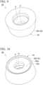
- FIGS. 9 and 10 are perspective views showing a cutting insert 40 in Modification Example 5.
- a lower surface 43 having a seating surface 43a having a flat surface perpendicular to the center line O and a pedestal 43b formed on the entire outer peripheral edge of the seating surface 43a are formed on a seating side.
- a top portion 43bc of the pedestal 43b has no grinding mark and protrudes outward beyond the seating surface 43a in the axial direction.
- the pedestal 3b is provided on the outer peripheral edge of the seating surface 3a, but the pedestal 3b is not limited thereto.
- the pedestal 3b may be provided in the seating surface 3a.
- the pedestal 3b may be provided not on the outer peripheral edge of the seating surface 3a but on an outer peripheral edge (outline) of the lower surface 3.
- each seating surface 3a is provided around the mounting hole 6 of the cutting insert, but the seating surface 3a is not limited thereto.
- a pair of the seating surfaces 3a may be provided on both sides of the mounting hole 6 in the radial direction, or a plurality of the seating surfaces 3a may be provided around the mounting hole 6.
- Each seating surface 3a may be a flat surface perpendicular to the center line O.
- a cutting insert and a cutting tool capable of, in a case of being applied to a single-sided cutting insert, achieving both cost reduction and securing flatness of a seating surface by eliminating a need for a grinding step for a lower surface including the seating surface.
Landscapes
- Engineering & Computer Science (AREA)
- Mechanical Engineering (AREA)
- Milling Processes (AREA)
- Cutting Tools, Boring Holders, And Turrets (AREA)
Abstract
Description
- The present invention relates to a cutting insert and a cutting tool. Priority is claimed on
Japanese Patent Application No. 2021-191001, filed November 25, 2021 - In general, in a manufacturing step of a single-sided cutting insert as described in
Patent Documents 1 and 2, a powder mixture of a hard metal component and a binder is press-formed to prepare a green compact for a cutting insert, and the green compact for a cutting insert is sintered in a state of being placed on a sintering plate. As described inPatent Document 3, although a contact reaction inhibitor is applied to a carbon sintering plate, unevenness is formed on a portion (a lower surface on a seating surface side) of a cutting insert that comes into contact with a sintering plate due to adhesion of the contact reaction inhibitor or sintering reaction marks. In a case where unevenness is formed on the seating surface of the cutting insert, an unstably clamped state is incurred when the cutting insert is mounted to a tool main body. -
- [Patent Document 1]
Japanese Unexamined Patent Application, First Publication No. H11-333616 - [Patent Document 2]
Japanese Unexamined Patent Application, First Publication No. 2005-319575 - [Patent Document 3]
Japanese Unexamined Patent Application, First Publication No. 2003-113404 - After the sintering, a polishing step of flattening the lower surface, which is to become the seating surface of the cutting insert, by removing the unevenness of the lower surface is required, and thus efforts and costs are required for manufacturing.
- The present invention has been made in view of such circumstances, and an object thereof is to provide a cutting insert and a cutting tool capable of, in a case of being applied to a single-sided cutting insert, achieving both cost reduction and securing flatness of a seating surface by eliminating a need for a grinding step for a lower surface including the seating surface.
- In order to solve such a problem and achieve the object, the present invention proposes the following means.
- A cutting insert according to an aspect of the present invention is a cutting insert having a plate shape and having a center line, including: an upper surface that forms one surface of two surfaces facing each other in an axial direction along the center line; a lower surface that forms the other surface of the two surfaces facing each other; a side surface that connects the upper surface and the lower surface in the axial direction; and a mounting hole that passes through the cutting insert in the axial direction, in which the side surface extends obliquely inward in a radial direction perpendicular to the center line from the upper surface toward the lower surface in the axial direction, the lower surface includes a seating surface having a flat surface perpendicular to the center line, and a pedestal having a protruding portion protruding from an outer peripheral edge of the seating surface in a direction away from the upper surface in the axial direction beyond the seating surface, and a top portion of the protruding portion of the pedestal is perpendicular to the center line.
- According to the configuration of the present embodiment, in the lower surface of the cutting insert, only the pedestal having the protruding portion protruding in the direction away from the upper surface beyond the seating surface comes into contact with a sintering plate, and the seating surface having the flat surface that abuts on an insert mounting seat does not come into contact with the sintering plate. Therefore, adhesion of a contact reaction inhibitor and generation of sintering reaction marks do not occur on the seating surface. Accordingly, a step of removing contact reaction inhibitor deposits and sintering reaction marks on the seating surface, that is, a grinding step for the lower surface is not required, so that manufacturing steps are shortened, and it is possible to achieve both cost reduction and securing flatness of the seating surface.
- In the cutting insert according to the aspect of the present invention, a configuration may be adopted in which a ridge between the upper surface and the side surface is inclined with respect to the flat surface perpendicular to the center line at a portion that protrudes most in the axial direction.
- In a cutting insert of which a side surface forming a flank face is not polished, in order to polish a lower surface, which is to be a seating surface of a single-sided insert having a cutting edge only on a ridge between an upper surface and the side surface, the upper surface needs to be brought into contact with a jig to hold the cutting insert. Since a contact area with the jig needs to be large in order to prevent a main cutting edge from being damaged by the contact with the jig, for example, the ridge between the upper surface and the side surface that protrudes most in a center line direction of the upper surface as shown in
FIG. 6 of Patent Document 1 requires a portion parallel to the lower surface, and a shape of a second cutting edge 26 is determined by this protruding flat surface. On the other hand, by using the lower surface according to the aspect of the present invention, it is possible to design all cutting edges of the cutting insert without limitation of a polishing step. Accordingly, as a cutting tool in which a cutting insert is mounted to an insert mounting seat of a tool main body that rotates about an axis, it is possible to set an optimum axial rake angle in an axial direction and an optimum radial rake angle in a radial direction. - In the cutting insert according to the aspect of the present invention, the top portion of the protruding portion of the pedestal may be provided with a flat surface.
- In addition, in the cutting insert according to the aspect of the present invention, a configuration may be adopted in which the top portion of the protruding portion of the pedestal has a ridge shape.
- According to this configuration, although there are disadvantages from the viewpoint of an effect of suppressing deformation during sintering, the wider seating surface enables stable abutting on the insert mounting seat of the tool main body.
- In addition, in the cutting insert according to the aspect of the present invention, a configuration may be adopted in which the pedestal is provided over an entire outer peripheral edge of the seating surface.
- According to this configuration, stable support is possible when the sintering process is performed during manufacturing of the cutting insert, and deformation during the sintering can be suppressed.
- In the cutting insert according to the aspect of the present invention, a configuration may be adopted in which the pedestal is provided along a part of the outer peripheral edge of the seating surface.
- A cutting tool according to another aspect of the present invention includes: a tool main body that is rotatable in a tool rotation direction about an axis of rotation and has an insert mounting seat to which the cutting insert is mounted, in which the insert mounting seat has a bottom surface on which the seating surface of the cutting insert abuts.
- According to this configuration, when the cutting insert is mounted to the tool main body, the seating surface of the cutting insert abuts on the bottom surface of the insert mounting seat, so that the cutting insert is mounted to the tool main body. Since the flat surfaces abut on each other, the cutting insert can be mounted to the tool main body without rattling, and a stably clamped state can be secured.
- According to the above aspects of the present invention, it is possible to provide a cutting insert and a cutting tool capable of, in a case of being applied to a single-sided cutting insert, achieving both cost reduction and securing flatness of a seating surface by eliminating a need for a grinding step for a lower surface including the seating surface.
-
-
FIG. 1 is a perspective view showing a cutting insert according to a first embodiment of the present invention from a rake face side. -
FIG. 2A is a plan view of the cutting insert according to the first embodiment of the present invention. -
FIG. 2B is a side view showing the cutting insert according to the first embodiment of the present invention from a long side side. -
FIG. 2C is a side view showing the cutting insert according to the first embodiment of the present invention from a short side side. -
FIG. 3 is a perspective view showing the cutting insert according to the first embodiment of the present invention from a seating surface side. -
FIG. 4 is a perspective view showing a configuration of a tip side of a tool main body. -
FIG. 5 is a perspective view showing a seating side of a cutting insert in Modification Example 1 of the first embodiment. -
FIG. 6 is a perspective view showing a seating side of a cutting insert in Modification Example 2 of the first embodiment. -
FIG. 7 is a perspective view showing a seating side of a cutting insert according to Modification Example 3 of the first embodiment. -
FIG. 8 is a perspective view showing a seating side of a cutting insert in Modification Example 4 of the first embodiment. -
FIG. 9 is a perspective view showing a cutting insert in Modification Example 5. -
FIG. 10 is a perspective view showing the cutting insert in Modification Example 5. - Hereinafter, a cutting insert according to each embodiment of the present invention will be described with reference to the drawings.
FIG. 1 is a perspective view showing a cutting insert 1 according to a first embodiment of the present invention from a rake face side.FIGS. 2A to 2C are three views (a plan view and side views) showing the cutting insert 1 according to the first embodiment of the present invention.FIG. 3 is a perspective view showing the cutting insert 1 according to the first embodiment of the present invention from a seating surface side. The cutting insert 1 of the present embodiment is removably mounted to a tool main body that rotates about an axis, and performs cutting work on a work material made of a metal material, such as steel. - The cutting insert 1 of the present embodiment shown in
FIGS. 1 ,2A to 2C , and 3 is formed of a hard material such as cemented carbide. The cutting insert 1 is formed in a plate shape having a polygonal shape that is rotationally symmetrical with respect to a center line O in the plan view seen from the center line O extending in a thickness direction. In the present embodiment, the cutting insert 1 has a rectangular shape in the plan view, but is not limited to this shape. - In the following description, a direction along the center line O may be simply referred to as a thickness direction. In addition, a direction orthogonal to the center line O may be simply referred to as a radial direction. Furthermore, a circumferential direction about an axis centered on the center line O may be simply referred to as a circumferential direction.
- The cutting insert 1 includes a rake face (upper surface) 2 forming one surface of two surfaces facing each other in an axial direction along the center line O, a
lower surface 3 forming the other surface of the two surfaces, side surfaces 4 that connects therake face 2 to thelower surface 3, cuttingedges 5 formed at intersecting ridges (ridges) 7 between therake face 2 and the side surfaces 4, and a mountinghole 6 provided coaxially with the center line O. The mountinghole 6 is a through hole that is formed in the thickness direction of the cutting insert 1 and opens to both therake face 2 and thelower surface 3. Theside surface 4 extends obliquely inward in the radial direction perpendicular to the center line O from therake face 2 toward thelower surface 3 in the axial direction. Thelower surface 3 has a size that is included inside a projection region of therake face 2 in the thickness direction. As shown inFIGS. 2A to 2C , the intersectingridge 7 between therake face 2 and theside surface 4 is inclined with respect to the flat surface perpendicular to the center line O at a portion that protrudes most in the axial direction. -
FIG. 4 is a perspective view showing a configuration of a tip side of a tool main body 10. - The cutting insert 1 is mounted to the tool main body 10 shown in
FIG. 4 and used as a cutting tool together with the tool main body 10. The cutting insert 1 is removably mounted to aninsert mounting seat 11 of the tool main body 10 rotatable about an axis of rotation CO by a clamp screw (not shown). The clamp screw is inserted into the mountinghole 6 of the cutting insert 1. The cutting insert 1 is restrained by theinsert mounting seat 11 of the tool main body 10 when the cutting insert 1 is mounted to the tool main body 10. Theinsert mounting seat 11 is a pedestal to which the cutting insert 1 is mounted. - The
insert mounting seat 11 has a bottom surface 1 1a, a longside wall surface 11b, and a shortside wall surface 11c. In addition, theinsert mounting seat 11 has a plurality of recessed grooves (recessed portions) 11d and 11e around thebottom surface 11a. The long side side recessed grooves (recessed portions) 11d are formed on both sides of thebottom surface 11a in the radial direction, and one thereof is formed between thebottom surface 11a and the longside wall surface 11b. The short side side recessed groove (recessed portion) 11e is formed between thebottom surface 11a and the shortside wall surface 11c. The long side side recessedgrooves 11d and the short side side recessed groove 11e are recessed in a direction opposite to a tool rotation direction T. - The
bottom surface 11a is a surface facing the tool rotation direction T of the tool main body 10. Thebottom surface 11a is a surface facing aseating surface 3a of the cutting insert 1, which will be described later, and has substantially the same area as thebottom surface 11a. Ascrew hole 13 into which the clamp screw 12 is inserted is formed substantially at a center of the bottom surface 1 1a. - As shown in
FIG. 1 , therake face 2 of the cutting insert 1 has aflat surface 2a provided around the mountinghole 6 and aninclined surface 2b inclined from thecutting edge 5 toward theflat surface 2a. Theflat surface 2a is a surface perpendicular to the center line O. - As shown in
FIG. 3 , thelower surface 3 of the cutting insert 1 includes theseating surface 3a that comes into contact with thebottom surface 11a of theinsert mounting seat 11 and is restrained, and a pedestal (protruding portion) 3b that does not come into contact with thebottom surface 11a of theinsert mounting seat 11. Specifically, thelower surface 3 includes theseating surface 3a formed of a flat surface perpendicular to the center line O and thepedestal 3b formed of a protruding portion protruding from an outer peripheral edge of theseating surface 3a in a direction away from therake face 2 in the axial direction beyond theseating surface 3a. A top portion 3bc of thepedestal 3b is perpendicular to the center line O. - The
seating surface 3a is the flat surface orthogonal to the center line O. Theseating surface 3a is parallel to theflat surface 2a on arake face 2 side. Theseating surface 3a is a surface that comes into contact with the bottom surface 1 1a of theinsert mounting seat 11. Theseating surface 3a has substantially the same area as or a slightly smaller area than thebottom surface 11a of theinsert mounting seat 11. The mountinghole 6 is open substantially at the center of theseating surface 3a. - The
pedestal 3b is formed throughout the circumferential direction (over an entire outer peripheral edge) of theseating surface 3a. In addition, thepedestal 3b is formed on the outer peripheral edge of theseating surface 3a. Thepedestal 3b protrudes outward in the axial direction from theseating surface 3a. That is, thepedestal 3b protrudes in a direction away from therake face 2 beyond theseating surface 3a in the axial direction. Accordingly, a recessed portion recessed inward in the axial direction is formed by theseating surface 3a and thepedestal 3b on a seating side of the cutting insert 1. - The top portion 3bc of the
pedestal 3b is provided with a flat surface perpendicular to the center line O, and there is no grinding mark on the entire flat surface. That is, in the present embodiment, the top portion 3bc of thepedestal 3b of the cutting insert 1 is sintered in a state of being in contact with a sintering plate, and is not subjected to grinding work after the sintering. - In the present embodiment, the
pedestal 3b is provided over the entire outer peripheral edge of theseating surface 3a, but is not limited thereto. Thepedestal 3b may be provided over a part of the outer peripheral edge. - In addition, in the present embodiment, the top portion 3bc of the
pedestal 3b has a flat surface perpendicular to the center line O, but is not limited thereto. The top portion 3bc of thepedestal 3b may have a surface other than the flat surface. For example, the top portion 3bc may have a curved surface forming a ridge shape. - As shown in
FIGS. 2B and2C , a height H of thepedestal 3b in the axial direction corresponds to an amount of step between theseating surface 3a and the top portion 3bc of thepedestal 3b. The height H of thepedestal 3b is constant throughout. The height H of thepedestal 3b is preferably in a range of, for example, 0.15 mm to 0.50 mm. In addition, the height H of thepedestal 3b is more preferably in a range of 0.20 mm to 0.40 mm, and is set to 0.30 mm in the present embodiment. - When the cutting insert 1 of the present embodiment is mounted to the tool main body 10 and the
seating surface 3a of the cutting insert 1 is in a state of being in contact with thebottom surface 11a of theinsert mounting seat 11, thepedestal 3b enters the long side side recessedgrooves 11d and the short side side recessed groove 11e of theinsert mounting seat 11 and thus does not come into contact with thebottom surface 11a of theinsert mounting seat 11. - With such a configuration, a restraining strength of the cutting insert 1 with respect to the tool main body 10 is secured mainly by a surface contact between the
bottom surface 11a and theseating surface 3a. Since the cutting insert 1 is restrained by theseating surface 3a and thebottom surface 11a which are flat against each other, rattling does not occur in the cutting insert 1, and a stably clamped state can be obtained for theinsert mounting seat 11 of the tool main body 10. - In addition, in the cutting insert 1, a portion (
pedestal 3b) that comes into contact with the sintering plate during the sintering is provided separately from theseating surface 3a, and the top portion 3bc of thepedestal 3b has a shape that does not come into contact with thebottom surface 11a of theinsert mounting seat 11 of the tool main body 10 when the cutting insert 1 is mounted to the tool main body 10, so that grinding work of the top portion 3bc of thepedestal 3b is not required. Since theseating surface 3a does not come into contact with the sintering plate, no sintering mark (fine unevenness) is generated on theseating surface 3a, and flatness is secured. Therefore, a grinding step that has been performed on the seating side of the cutting insert 1 in the related art can be omitted. Therefore, according to the cutting insert 1 of the present embodiment, it is possible to realize both cost reduction and securing the flatness of theseating surface 3a. - In addition, in the present embodiment, the
pedestal 3b is provided on the outer peripheral edge of theseating surface 3a. Accordingly, the area of theseating surface 3a can be maximized on the seating side of the cutting insert 1, and the restraining strength with respect to the tool main body 10 can be increased. - By including the tool main body 10 to which the cutting insert 1 of the present embodiment is mounted, a cutting tool 100 having high machining accuracy can be obtained.
- While the first embodiment of the present invention has been described in detail with reference to the drawings, specific configurations are not limited to the embodiment, and design changes and the like within a range that does not deviate from the gist of the present invention are also included.
- For example, in the cutting insert 1 of the first embodiment, the
pedestal 3b is formed over the entire outer peripheral edge of theseating surface 3a, but the shape of thepedestal 3b of the cutting insert 1 is not limited to the above-described shape. - Hereinafter, some modification examples of the
pedestal 3b will be described. In the following description, configurations common to those already described are assigned the same reference numerals, and repeated descriptions thereof will be omitted. -
FIG. 5 is a perspective view showing a seating side of a cutting insert 1A in Modification Example 1 of the first embodiment. - As shown in
FIG. 5 , in the cutting insert 1A of Modification Example 1, a pedestal 3Ab is formed at each of fourcorner portions 3f on alower surface 3 side. All of the four pedestals 3Ab have a symmetrical shape in a long side direction and a short side direction of the cutting insert 1. Each pedestal 3Ab has a first portion 3b1 extending along a correspondinglong side 3g and a second portion 3b2 extending along a correspondingshort side 3h, and has an L shape in a plan view. Between the pedestals 3Ab adjacent to each other in the circumferential direction, theseating surface 3a located on therake face 2 side from the top portion 3bc of each pedestal 3Ab in the axial direction is present. -
FIG. 6 is a perspective view showing a seating side of acutting insert 1B in Modification Example 2 of the first embodiment. - As shown in
FIG. 6 , in thecutting insert 1B of Modification Example 2, a pedestal 3Bb is formed along each of the pair oflong sides 3g of theseating surface 3a. Each pedestal 3Bb is formed over an entirelong side 3g. -
FIG. 7 is a perspective view showing a seating side of a cutting insert 1C in Modification Example 3 of the first embodiment. - As shown in
FIG. 7 , in the cutting insert 1C of Modification Example 3, a pedestal 3Cb is formed along each of the pair ofshort sides 3h of theseating surface 3a. Each pedestal 3Cb is formed over an entireshort side 3h. -
FIG. 8 is a perspective view showing a seating side of a cuttinginsert 1D in Modification Example 4 of the first embodiment. - As shown in
FIG. 8 , in the cuttinginsert 1D of Modification Example 4, pedestals 3Db are formed to include the pair ofshort sides 3h and the fourcorner portions 3f in the outer peripheral edge of theseating surface 3a. The pedestal 3Db is provided along the entireshort side 3h and portions of thelong side 3g from both ends of theshort side 3h. - According to Modification Examples 1 to 4, the flatness of the
seating surface 3a can be secured while a horizontal posture during firing is maintained by thepedestal 3b. In addition, by including thepedestal 3b in a predetermined range of at least the fourcorner portions 3f, the pair oflong sides 3g, and the pair ofshort sides 3h on the outer peripheral edge of theseating surface 3a, it is possible to reduce material costs. Furthermore, the top portion 3bc of eachpedestal 3b in Modification Examples 1 to 4 has no grinding mark, and manufacturing steps can be simplified as in the first embodiment. - For example, the shape of the cutting insert in the plan view is not limited to the shapes of the above-described embodiments.
- The shape of the cutting insert in the plan view may be other than a rectangular shape, and may be a triangular shape, a square shape, or a circular shape.
-
FIGS. 9 and 10 are perspective views showing a cutting insert 40 in Modification Example 5. - For example, as shown in
FIGS. 9 and 10 , in a case of the cutting insert 40 having a circular shape in the plan view, it is preferable that alower surface 43 having aseating surface 43a having a flat surface perpendicular to the center line O and apedestal 43b formed on the entire outer peripheral edge of theseating surface 43a are formed on a seating side. A top portion 43bc of thepedestal 43b has no grinding mark and protrudes outward beyond theseating surface 43a in the axial direction. - In each of the above-described embodiments and modification examples, a configuration is adopted in which the
pedestal 3b is provided on the outer peripheral edge of theseating surface 3a, but thepedestal 3b is not limited thereto. For example, thepedestal 3b may be provided in theseating surface 3a. Alternatively, thepedestal 3b may be provided not on the outer peripheral edge of theseating surface 3a but on an outer peripheral edge (outline) of thelower surface 3. - In addition, in each of the above-described embodiments and modification examples, a configuration is adopted in which one
seating surface 3a is provided around the mountinghole 6 of the cutting insert, but theseating surface 3a is not limited thereto. For example, a pair of the seating surfaces 3a may be provided on both sides of the mountinghole 6 in the radial direction, or a plurality of the seating surfaces 3a may be provided around the mountinghole 6. Eachseating surface 3a may be a flat surface perpendicular to the center line O. - According to the present invention, it is possible to provide a cutting insert and a cutting tool capable of, in a case of being applied to a single-sided cutting insert, achieving both cost reduction and securing flatness of a seating surface by eliminating a need for a grinding step for a lower surface including the seating surface.
-
- 1 (1A, 1B, 1C, 1D): Cutting insert of first embodiment (Modification Examples 1 to 4)
- 2: Rake face (upper surface of first embodiment)
- 3: Lower surface of first embodiment
- 3a: Seating surface of cutting insert of first embodiment
- 3b (3Ab, 3Bb, 3Cb, 3Db): Pedestal of first embodiment (Modification Examples 1 to 4)
- 3bc: Top portion of pedestal of first embodiment
- 3f: Corner portion
- 3g: Long side
- 3h: Short side
- 4: Side surface
- 6: Mounting hole
- 7: Ridge
- 10: Tool main body
- 11: Insert mounting seat
- 11a, 11b, 11c: Bottom surface, long side wall surface, short side wall surface of insert mounting seat
- 40: Cutting insert of Modification Example 5
- 43: Lower surface of Modification Example 5
- 43a: Seating surface of Modification Example 5
- 43b: Pedestal of Modification Example 5
- 43bc: Top portion of pedestal of Modification Example 5
- 100: Cutting tool
- O: Center line
Claims (7)
- A cutting insert having a plate shape and having a center line, comprising:an upper surface that forms one surface of two surfaces facing each other in an axial direction along the center line;a lower surface that forms an other surface of the two surfaces facing each other;a side surface that connects the upper surface and the lower surface in the axial direction; anda mounting hole that passes through the cutting insert in the axial direction,wherein the side surface extends obliquely inward in a radial direction perpendicular to the center line from the upper surface toward the lower surface in the axial direction,the lower surface includes a seating surface having a flat surface perpendicular to the center line, and a pedestal having a protruding portion protruding from an outer peripheral edge of the seating surface in a direction away from the upper surface in the axial direction beyond the seating surface, anda top portion of the protruding portion of the pedestal is perpendicular to the center line.
- The cutting insert according to Claim 1, wherein a ridge between the upper surface and the side surface is inclined with respect to the flat surface perpendicular to the center line at a portion that protrudes most in the axial direction.
- The cutting insert according to Claim 1 or 2, wherein the top portion of the protruding portion of the pedestal is provided with a flat surface.
- The cutting insert according to any one of Claims 1 to 3, wherein the top portion of the protruding portion of the pedestal has a ridge shape.
- The cutting insert according to any one of Claims 1 to 4, wherein the pedestal is provided over an entire outer peripheral edge of the seating surface.
- The cutting insert according to any one of Claims 1 to 4, wherein the pedestal is provided along a part of the outer peripheral edge of the seating surface.
- A cutting tool comprising:the cutting insert according to any one of Claims 1 to 6;a tool main body that is rotatable in a tool rotation direction about an axis of rotation and has an insert mounting seat to which the cutting insert is mounted,wherein the insert mounting seat has a bottom surface on which the seating surface of the cutting insert abuts.
Applications Claiming Priority (2)
| Application Number | Priority Date | Filing Date | Title |
|---|---|---|---|
| JP2021191001A JP7707877B2 (en) | 2021-11-25 | 2021-11-25 | Cutting inserts and cutting tools |
| PCT/JP2022/043287 WO2023095819A1 (en) | 2021-11-25 | 2022-11-24 | Cutting insert and cutting tool |
Publications (2)
| Publication Number | Publication Date |
|---|---|
| EP4438210A1 true EP4438210A1 (en) | 2024-10-02 |
| EP4438210A4 EP4438210A4 (en) | 2025-11-19 |
Family
ID=86539529
Family Applications (1)
| Application Number | Title | Priority Date | Filing Date |
|---|---|---|---|
| EP22898601.4A Pending EP4438210A4 (en) | 2021-11-25 | 2022-11-24 | CUTTING INSERT AND CUTTING TOOL |
Country Status (5)
| Country | Link |
|---|---|
| US (1) | US20250010377A1 (en) |
| EP (1) | EP4438210A4 (en) |
| JP (1) | JP7707877B2 (en) |
| CN (1) | CN118369174A (en) |
| WO (1) | WO2023095819A1 (en) |
Family Cites Families (15)
| Publication number | Priority date | Publication date | Assignee | Title |
|---|---|---|---|---|
| SE510851C2 (en) * | 1996-12-23 | 1999-06-28 | Sandvik Ab | Cuts and holders for cutting metalworking |
| SE512040C2 (en) | 1998-05-06 | 2000-01-17 | Sandvik Ab | Inserts for stick cutters |
| JP4709374B2 (en) | 2000-12-18 | 2011-06-22 | 住友電工ハードメタル株式会社 | Throw-away inserts for turning tools and insert mounting seats for turning tools |
| JP2003113404A (en) | 2001-10-03 | 2003-04-18 | Sumitomo Electric Ind Ltd | Hard alloy sintering method |
| JP4706284B2 (en) | 2004-04-06 | 2011-06-22 | 三菱マテリアル株式会社 | Insert detachable rolling tool |
| SE529396C2 (en) * | 2005-12-08 | 2007-07-31 | Sandvik Intellectual Property | Tools and inserts for chip separating machining with secondary tools |
| SE531502C2 (en) * | 2007-06-05 | 2009-04-28 | Sandvik Intellectual Property | Tools for chip separating machining as well as basic body and indexable cutting for this |
| DE202008018646U1 (en) | 2008-08-31 | 2017-03-24 | Iscar Ltd. | cutting insert |
| JP5453702B2 (en) | 2009-11-25 | 2014-03-26 | 住友電工ハードメタル株式会社 | Replaceable tip and throw-away cutter |
| JP5403167B2 (en) | 2010-09-30 | 2014-01-29 | 株式会社タンガロイ | Replaceable cutting tool |
| JP2017064869A (en) | 2015-10-01 | 2017-04-06 | 京セラ株式会社 | CUTTING INSERT, CUTTING TOOL, AND CUTTING PRODUCT PRODUCTION METHOD USING THE SAME |
| CN108115156B (en) | 2016-11-29 | 2020-11-06 | 京瓷株式会社 | Cutting tool and method for manufacturing cut product |
| WO2018105752A1 (en) | 2016-12-09 | 2018-06-14 | 三菱日立ツール株式会社 | Cutting insert and replaceable cutting edge rotary cutting tool |
| EP3338927B1 (en) | 2016-12-22 | 2023-07-26 | Sandvik Intellectual Property AB | Cutting insert and shoulder milling tool |
| CN113746550B (en) | 2020-05-27 | 2024-12-17 | 莫列斯有限公司 | Light receiving device |
-
2021
- 2021-11-25 JP JP2021191001A patent/JP7707877B2/en active Active
-
2022
- 2022-11-24 CN CN202280077015.0A patent/CN118369174A/en active Pending
- 2022-11-24 EP EP22898601.4A patent/EP4438210A4/en active Pending
- 2022-11-24 US US18/712,267 patent/US20250010377A1/en active Pending
- 2022-11-24 WO PCT/JP2022/043287 patent/WO2023095819A1/en not_active Ceased
Also Published As
| Publication number | Publication date |
|---|---|
| WO2023095819A1 (en) | 2023-06-01 |
| CN118369174A (en) | 2024-07-19 |
| EP4438210A4 (en) | 2025-11-19 |
| JP7707877B2 (en) | 2025-07-15 |
| JP2023077654A (en) | 2023-06-06 |
| US20250010377A1 (en) | 2025-01-09 |
Similar Documents
| Publication | Publication Date | Title |
|---|---|---|
| US8777524B2 (en) | Cutting insert | |
| US6503028B1 (en) | Sintered cutting insert having center hole for clamp screw | |
| CN101754830A (en) | Cutting insert comprising a stabilising double-sided facet | |
| US10160083B2 (en) | Method for manufacturing cubic boron nitride cutting tool and cubic boron nitride cutting tool | |
| KR101743096B1 (en) | Insert | |
| US6769844B2 (en) | Cutting insert and method of making the same | |
| JP5366100B2 (en) | Negative tip with double positive flank | |
| US11179785B2 (en) | Cutting insert and indexable edge rotary cutting tool | |
| RU2747665C1 (en) | Plate and cutting tool assembly containing such plate | |
| CN107635704A (en) | Tool bodies and cutting tools | |
| CN109382529B (en) | Cutting insert and cutting tool | |
| CN113118484B (en) | Cutting insert and turning tool using the same | |
| US20250010377A1 (en) | Cutting insert and cutting tool | |
| JP4403936B2 (en) | Throwaway tip | |
| JP2005342871A (en) | Throw-away tip | |
| JP4810902B2 (en) | Inserts and turning tools | |
| JP4242168B2 (en) | Square punch and manufacturing method thereof | |
| JPH088011Y2 (en) | Throwaway type rolling tool | |
| JPH10309617A (en) | Indexable tip | |
| JP2002346832A (en) | Indexable tip | |
| JPH0627001U (en) | Throw-away tip |
Legal Events
| Date | Code | Title | Description |
|---|---|---|---|
| STAA | Information on the status of an ep patent application or granted ep patent |
Free format text: STATUS: THE INTERNATIONAL PUBLICATION HAS BEEN MADE |
|
| PUAI | Public reference made under article 153(3) epc to a published international application that has entered the european phase |
Free format text: ORIGINAL CODE: 0009012 |
|
| STAA | Information on the status of an ep patent application or granted ep patent |
Free format text: STATUS: REQUEST FOR EXAMINATION WAS MADE |
|
| 17P | Request for examination filed |
Effective date: 20240523 |
|
| AK | Designated contracting states |
Kind code of ref document: A1 Designated state(s): AL AT BE BG CH CY CZ DE DK EE ES FI FR GB GR HR HU IE IS IT LI LT LU LV MC ME MK MT NL NO PL PT RO RS SE SI SK SM TR |
|
| DAV | Request for validation of the european patent (deleted) | ||
| DAX | Request for extension of the european patent (deleted) | ||
| A4 | Supplementary search report drawn up and despatched |
Effective date: 20251021 |
|
| RIC1 | Information provided on ipc code assigned before grant |
Ipc: B23C 5/20 20060101AFI20251015BHEP Ipc: B23B 27/16 20060101ALI20251015BHEP Ipc: B23C 5/10 20060101ALI20251015BHEP |