EP4438196A1 - Molding device and molding method - Google Patents
Molding device and molding method Download PDFInfo
- Publication number
- EP4438196A1 EP4438196A1 EP22898368.0A EP22898368A EP4438196A1 EP 4438196 A1 EP4438196 A1 EP 4438196A1 EP 22898368 A EP22898368 A EP 22898368A EP 4438196 A1 EP4438196 A1 EP 4438196A1
- Authority
- EP
- European Patent Office
- Prior art keywords
- metal pipe
- forming
- pipe material
- restriction
- deviation
- Prior art date
- Legal status (The legal status is an assumption and is not a legal conclusion. Google has not performed a legal analysis and makes no representation as to the accuracy of the status listed.)
- Pending
Links
Images





Classifications
-
- B—PERFORMING OPERATIONS; TRANSPORTING
- B21—MECHANICAL METAL-WORKING WITHOUT ESSENTIALLY REMOVING MATERIAL; PUNCHING METAL
- B21D—WORKING OR PROCESSING OF SHEET METAL OR METAL TUBES, RODS OR PROFILES WITHOUT ESSENTIALLY REMOVING MATERIAL; PUNCHING METAL
- B21D26/00—Shaping without cutting otherwise than using rigid devices or tools or yieldable or resilient pads, i.e. applying fluid pressure or magnetic forces
- B21D26/02—Shaping without cutting otherwise than using rigid devices or tools or yieldable or resilient pads, i.e. applying fluid pressure or magnetic forces by applying fluid pressure
- B21D26/033—Deforming tubular bodies
- B21D26/035—Deforming tubular bodies including an additional treatment performed by fluid pressure, e.g. perforating
-
- B—PERFORMING OPERATIONS; TRANSPORTING
- B21—MECHANICAL METAL-WORKING WITHOUT ESSENTIALLY REMOVING MATERIAL; PUNCHING METAL
- B21D—WORKING OR PROCESSING OF SHEET METAL OR METAL TUBES, RODS OR PROFILES WITHOUT ESSENTIALLY REMOVING MATERIAL; PUNCHING METAL
- B21D19/00—Flanging or other edge treatment, e.g. of tubes
- B21D19/08—Flanging or other edge treatment, e.g. of tubes by single or successive action of pressing tools, e.g. vice jaws
-
- B—PERFORMING OPERATIONS; TRANSPORTING
- B21—MECHANICAL METAL-WORKING WITHOUT ESSENTIALLY REMOVING MATERIAL; PUNCHING METAL
- B21D—WORKING OR PROCESSING OF SHEET METAL OR METAL TUBES, RODS OR PROFILES WITHOUT ESSENTIALLY REMOVING MATERIAL; PUNCHING METAL
- B21D24/00—Special deep-drawing arrangements in, or in connection with, presses
- B21D24/10—Devices controlling or operating blank holders independently, or in conjunction with dies
-
- B—PERFORMING OPERATIONS; TRANSPORTING
- B21—MECHANICAL METAL-WORKING WITHOUT ESSENTIALLY REMOVING MATERIAL; PUNCHING METAL
- B21D—WORKING OR PROCESSING OF SHEET METAL OR METAL TUBES, RODS OR PROFILES WITHOUT ESSENTIALLY REMOVING MATERIAL; PUNCHING METAL
- B21D26/00—Shaping without cutting otherwise than using rigid devices or tools or yieldable or resilient pads, i.e. applying fluid pressure or magnetic forces
- B21D26/02—Shaping without cutting otherwise than using rigid devices or tools or yieldable or resilient pads, i.e. applying fluid pressure or magnetic forces by applying fluid pressure
- B21D26/033—Deforming tubular bodies
-
- B—PERFORMING OPERATIONS; TRANSPORTING
- B21—MECHANICAL METAL-WORKING WITHOUT ESSENTIALLY REMOVING MATERIAL; PUNCHING METAL
- B21D—WORKING OR PROCESSING OF SHEET METAL OR METAL TUBES, RODS OR PROFILES WITHOUT ESSENTIALLY REMOVING MATERIAL; PUNCHING METAL
- B21D26/00—Shaping without cutting otherwise than using rigid devices or tools or yieldable or resilient pads, i.e. applying fluid pressure or magnetic forces
- B21D26/02—Shaping without cutting otherwise than using rigid devices or tools or yieldable or resilient pads, i.e. applying fluid pressure or magnetic forces by applying fluid pressure
- B21D26/033—Deforming tubular bodies
- B21D26/039—Means for controlling the clamping or opening of the moulds
-
- B—PERFORMING OPERATIONS; TRANSPORTING
- B21—MECHANICAL METAL-WORKING WITHOUT ESSENTIALLY REMOVING MATERIAL; PUNCHING METAL
- B21D—WORKING OR PROCESSING OF SHEET METAL OR METAL TUBES, RODS OR PROFILES WITHOUT ESSENTIALLY REMOVING MATERIAL; PUNCHING METAL
- B21D26/00—Shaping without cutting otherwise than using rigid devices or tools or yieldable or resilient pads, i.e. applying fluid pressure or magnetic forces
- B21D26/02—Shaping without cutting otherwise than using rigid devices or tools or yieldable or resilient pads, i.e. applying fluid pressure or magnetic forces by applying fluid pressure
- B21D26/033—Deforming tubular bodies
- B21D26/047—Mould construction
Definitions
- the present disclosure relates to a forming device and a forming method.
- a forming device used for forming a metal pipe is known.
- PTL 1 described below discloses a forming device that includes a forming tool including a lower die and an upper die paired with each other, and a fluid supply unit for supplying a fluid into a metal pipe material held between the upper and lower dies.
- the metal pipe having a flange is formed by crushing both sides of the metal pipe material in a width direction with the upper die and the lower die.
- such a forming device has a problem in that it is difficult to form a flange portion to a desired size because when the flange portion is expanding in the width direction, the expansion cannot be restricted.
- a deviation of the metal pipe material can be restricted by providing a restriction member on a lateral side of the metal pipe material.
- an optimal restriction amount, a contact timing, and the like may be different depending on a position in a longitudinal direction of the metal pipe material. In such a case, there is a problem in that a variation occurs in a size of the flange portion of the metal pipe after forming.
- the present disclosure has been made to solve such a problem, and an object of the present disclosure is to provide a forming device and a forming method capable of reducing a variation in size of a flange portion of a metal pipe after forming.
- a forming device that forms a metal pipe with a flange from a metal pipe material, the forming device including a forming tool that forms the metal pipe; and a restriction member that restricts a deviation of the metal pipe material during forming, in which the restriction member is divided into a plurality of pieces in a longitudinal direction of the metal pipe material during forming.
- the forming device includes the forming tool that forms the metal pipe, and the restriction member that restricts the deviation of the metal pipe material during forming. Therefore, the forming tool can perform forming while restricting the deviation of the metal pipe material with the restriction member.
- the restriction member is divided into a plurality of pieces in the longitudinal direction of the metal pipe material during forming. Therefore, the divided restriction members can restrict the deviation at each position in the longitudinal direction with a restriction amount and a contact timing suitable for each position. From the above, it is possible to reduce a variation in size of a flange portion of the metal pipe after forming.
- the plurality of divided restriction members may be individually controlled. Accordingly, the divided restriction members are individually controlled such that a restriction amount and a contact timing suitable for each position are set at each position in the longitudinal direction.
- the restriction member may restrict the deviation of the metal pipe material before forming.
- the restriction member can reduce the deviation of the metal pipe material in a stage before forming.
- the restriction member may restrict a deviation of a planned flange portion that becomes a flange portion after completion.
- the restriction member can reduce a variation in size of the flange portion by restricting the deviation of the planned flange portion itself that becomes the flange portion.
- a forming method is a forming method of forming a metal pipe with a flange from a metal pipe material, the forming method including a step of restricting a deviation of the metal pipe material with a restriction member during forming of the metal pipe, in which in the step, the deviation of the metal pipe material is restricted by the restriction member divided into a plurality of pieces in a longitudinal direction of the metal pipe material during forming.
- a forming device capable of reducing a variation in size of a flange portion of a metal pipe after forming.
- Fig. 1 is a schematic configuration view of a forming device 1 according to the present embodiment.
- the forming device 1 is a device that forms a metal pipe having a hollow shape by blow forming.
- the forming device 1 is installed on a horizontal plane.
- the forming device 1 includes a forming tool (forming die) 2, a drive mechanism 3, a holding unit 4, a heating unit 5, a fluid supply unit 6, a cooling unit 7, and a control unit 8.
- a metal pipe material 40 refers to a hollow article before completion of the forming by the forming device 1.
- the metal pipe material 40 is a steel-type pipe material that can be hardened.
- a direction in which the metal pipe material 40 extends during forming may be referred to as a "longitudinal direction”
- a direction perpendicular to the longitudinal direction may be referred to as a "width direction”.
- the forming tool 2 is a die that forms a metal pipe 140 from the metal pipe material 40, and includes a lower die 11 and an upper die 12 that face each other in a vertical direction.
- the lower die 11 and the upper die 12 are made of steel blocks.
- Each of the lower die 11 and the upper die 12 is provided with a recessed portion in which the metal pipe material 40 is accommodated.
- the lower die 11 is fixed to a base stage 13 via a die holder or the like.
- the upper die 12 is fixed to a slide of the drive mechanism 3 via a die holder or the like.
- the drive mechanism 3 is a mechanism that moves at least one of the lower die 11 and the upper die 12.
- the drive mechanism 3 has a configuration in which only the upper die 12 is moved.
- the drive mechanism 3 includes a slide 21 that moves the upper die 12 such that the lower die 11 and the upper die 12 are joined together, and a pull-back cylinder 22 serving as an actuator that generates a force for pulling the slide 21 upward, a main cylinder 23 serving as a drive source that downward-pressurizes the slide 21, and a drive source 24 that applies a driving force to the main cylinder 23.
- the holding unit 4 is a mechanism that holds the metal pipe material 40 disposed between the lower die 11 and the upper die 12.
- the holding unit 4 includes a lower electrode 26 and an upper electrode 27 that hold the metal pipe material 40 on one end side in the longitudinal direction of the forming tool 2, and a lower electrode 26 and an upper electrode 27 that holds the metal pipe material 40 on the other end side in the longitudinal direction of the forming tool 2.
- the lower electrodes 26 and the upper electrodes 27 on both sides in the longitudinal direction hold the metal pipe material 40 by sandwiching vicinities of the end portions of the metal pipe material 40 from the vertical direction.
- groove portions having a shape corresponding to an outer peripheral surface of the metal pipe material 40 are formed on an upper surface of the lower electrode 26 and a lower surface of the upper electrode 27.
- the lower electrode 26 and the upper electrode 27 are provided with drive mechanisms (not shown) and are movable independently in the vertical direction.
- the heating unit 5 heats the metal pipe material 40.
- the heating unit 5 is a mechanism that heats the metal pipe material 40 by energizing the metal pipe material 40.
- the heating unit 5 heats the metal pipe material 40 in a state in which the metal pipe material 40 is spaced apart from the lower die 11 and the upper die 12 between the lower die 11 and the upper die 12.
- the heating unit 5 includes the lower electrodes 26 and the upper electrodes 27 on both sides in the longitudinal direction as described above, and a power supply 28 that causes a current to flow through the metal pipe material 40 via the electrodes 26 and 27.
- the heating unit may be disposed in a preceding process of the forming device 1 and may perform heating externally.
- the fluid supply unit 6 is a mechanism that supplies a high-pressure fluid into the metal pipe material 40 held between the lower die 11 and the upper die 12.
- the fluid supply unit 6 supplies the high-pressure fluid into the metal pipe material 40 that has been brought into a high-temperature state by being heated by the heating unit 5 and expands the metal pipe material 40.
- the fluid supply unit 6 is provided on both end sides of the forming tool 2 in the longitudinal direction.
- the fluid supply unit 6 includes a nozzle 31 that supplies a fluid from an opening portion of an end portion of the metal pipe material 40 to the inside of the metal pipe material 40, a drive mechanism 32 that moves the nozzle 31 forward and backward with respect to the opening portion of the metal pipe material 40, and a supply source 33 that supplies the high-pressure fluid into the metal pipe material 40 via the nozzle 31.
- the drive mechanism 32 causes the nozzle 31 to be brought into close contact with the end portion of the metal pipe material 40 in a state in which sealing performance is secured during fluid supply and exhaust, and causes the nozzle 31 to be spaced apart from the end portion of the metal pipe material 40 at other times.
- the fluid supply unit 6 may supply a gas such as high-pressure air or an inert gas as the fluid.
- the fluid supply unit 6 may include the heating unit 5 together with the holding unit 4 having a mechanism that moves the metal pipe material 40 in the vertical direction as the same device.
- Components of the holding unit 4, the heating unit 5, and the fluid supply unit 6 may be configured as a unitized heating and expanding unit 150.
- Fig. 2A is a schematic side view showing the heating and expanding unit 150.
- Fig. 2B is a cross-sectional view showing a state when the nozzle 31 has sealed the metal pipe material 40.
- the heating and expanding unit 150 includes the above-described lower electrode 26 and upper electrode 27, an electrode mounting unit 151 on which the electrodes 26 and 27 are mounted, the above-described nozzle 31 and drive mechanism 32, an elevating unit 152, and a unit base 153.
- the electrode mounting unit 151 includes an elevating frame 154 and electrode frames 156 and 157.
- the electrode frames 156 and 157 function as a part of a drive mechanism 60 that supports and moves each of the electrodes 26 and 27.
- the drive mechanism 32 drives the nozzle 31 and lifts and lowers together with the electrode mounting unit 151.
- the drive mechanism 32 includes a piston 161 that holds the nozzle 31, and a cylinder 162 that drives the piston.
- the elevating unit 152 includes an elevating frame base 64 attached to an upper surface of the unit base 153, and an elevating actuator 166 that applies an elevating operation to the elevating frame 154 of the electrode mounting unit 151 by the elevating frame base 64.
- the elevating frame base 64 includes guide portions 64a and 64b that guide the elevating operation of the elevating frame 154 with respect to the unit base 153.
- the elevating unit 152 functions as a part of the drive mechanism 60 of the holding unit 4.
- the heating and expanding unit 150 includes a plurality of the unit bases 153 of which upper surfaces have different inclination angles, and is allowed to collectively change and adjust inclination angles of the lower electrode 26 and the upper electrode 27, the nozzle 31, the electrode mounting unit 151, the drive mechanism 32, and the elevating unit 152 by replacing the unit bases 153.
- the nozzle 31 is a cylindrical member into which the end portion of the metal pipe material 40 can be inserted.
- the nozzle 31 is supported by the drive mechanism 32 such that a center line of the nozzle 31 coincides with a reference line SL1.
- An inner diameter of a feed port 31a at an end portion of the nozzle 31 on the side of the metal pipe material 40 substantially coincides with an outer diameter of the metal pipe material 40 after expansion forming.
- the nozzle 31 supplies the high-pressure fluid from an internal flow path 163 to the metal pipe material 40.
- the high-pressure fluid include a gas and the like.
- the cooling unit 7 is a mechanism for cooling the forming tool 2. By cooling the forming tool 2, the cooling unit 7 can rapidly cool the metal pipe material 40 when the expanded metal pipe material 40 has come into contact with the forming surface of the forming tool 2.
- the cooling unit 7 includes a flow path 36 formed inside the lower die 11 and the upper die 12, and a water circulation mechanism 37 that supplies cooling water to the flow path 36 and circulates the cooling water.
- the control unit 8 is a device that controls the entire forming device 1.
- the control unit 8 controls the drive mechanism 3, the holding unit 4, the heating unit 5, the fluid supply unit 6, and the cooling unit 7.
- the control unit 8 repeatedly performs an operation of forming the metal pipe material 40 with the forming tool 2.
- control unit 8 controls, for example, a transport timing from a transport device such as a robot arm to dispose the metal pipe material 40 between the lower die 11 and the upper die 12 in an open state.
- the control unit 8 may allow a worker to manually dispose the metal pipe material 40 between the lower die 11 and the upper die 12.
- the control unit 8 controls an actuator of the holding unit 4 and the like such that the metal pipe material 40 is supported by the lower electrodes 26 on both sides in the longitudinal direction, and then the upper electrodes 27 are lowered to sandwich the metal pipe material 40.
- the control unit 8 controls the heating unit 5 to energize and heat the metal pipe material 40. Accordingly, an axial current flows through the metal pipe material 40, and an electric resistance of the metal pipe material 40 itself causes the metal pipe material 40 itself to generate heat due to Joule heat.
- the control unit 8 controls the drive mechanism 3 to lower the upper die 12 and bring the upper die 12 close to the lower die 11 to close the forming tool 2.
- the control unit 8 controls the fluid supply unit 6 to seal the opening portions of both ends of the metal pipe material 40 with the nozzle 31 and supply the fluid. Accordingly, the metal pipe material 40 softened by heating expands and comes into contact with the forming surface of the forming tool 2. Then, the metal pipe material 40 is formed so as to follow a shape of the forming surface of the forming tool 2.
- a part of the metal pipe material 40 is made to enter a gap between the lower die 11 and the upper die 12, and then die closing is further performed to crush the entering part to form a flange portion.
- quenching of the metal pipe material 40 is performed by being rapidly cooled with the forming tool 2 cooled by the cooling unit 7.
- the detailed configuration of the forming device 1 will be described with reference to Figs. 3 and 4 .
- a metal pipe 41 formed by the forming tool 2 will be described with reference to Fig. 7 .
- the metal pipe 41 includes a hollow pipe portion 41a and flange portions 41b and 41c protruding to both sides in the width direction.
- the pipe portion 41a has a rectangular tubular shape.
- a shape of the pipe portion 41a is not particularly limited and may be any shape depending on applications.
- the flange portions 41b and 41c are formed by crushing both end portions of the metal pipe material 40 in the width direction with the dies 11 and 12.
- a protrusion portion in the metal pipe 41 after completion of forming is referred to as a "flange portion”.
- a location planned to become the flange portion after the completion is referred to as a "planned flange portion”.
- a shape of the "planned flange portion" changes depending on a degree of progress of forming. As shown in Fig. 4 , the metal pipe material 40 (and the metal pipe 41) is curved so as to protrude to one side in the width direction when viewed from the vertical direction.
- the shape of the metal pipe material 40 is not particularly limited and is not limited to a shape curved at one location.
- the metal pipe material 40 may have a complex shape that is curved at a plurality of locations, or may have a linear shape.
- the lower die 11 includes a planar portion 51 expanding in the width direction, a recessed portion 52 formed at a central position in the width direction of the planar portion 51, and support portions 53 and 54 formed at both outer end portions in the width direction.
- the recessed portion 52 is a portion that forms a lower portion of the pipe portion 41a of the metal pipe 41 (refer to Fig. 7 ).
- both sides of the recessed portion 52 in the width direction are configured as forming surfaces for forming the flange portions 41b and 41c (refer to Fig. 7 ).
- the support portions 53 and 54 are portions that protrude upward from the planar portion 51.
- the support portion 53 is a portion that supports a restriction member 14 on a lateral side
- the support portion 54 is a portion that supports a restriction member 15 on a lateral side.
- the upper die 12 includes a planar portion 61 expanding in the width direction and a forming body portion 62 protruding downward at a central position of the planar portion 61 in the width direction.
- the forming body portion 62 has a substantially rectangular cross-sectional shape extending downward from the planar portion 61.
- the forming body portion 62 includes a recessed portion 63 on a lower surface 62a.
- the recessed portion 63 is a portion that forms an upper portion of the pipe portion 41a of the metal pipe 41 (refer to Fig. 7 ).
- the lower surface 62a of the forming body portion 62 is configured as forming surfaces for forming the flange portions 41b and 41c on both sides of the recessed portion 63 in the width direction (refer to Fig. 7 ).
- the forming body portion 62 has side surfaces 62b and 62c on both sides in the width direction.
- the restriction member 14 on a lateral side is disposed on one side of the metal pipe material 40 in the width direction.
- the restriction member 15 on a lateral side is disposed on the other side of the metal pipe material 40 in the width direction.
- the restriction members 14 and 15 are members that restrict a deviation of the metal pipe material 40 during forming. In a case where a deviation of the metal pipe material 40 in the width direction becomes equal to or larger than a predetermined amount, the restriction members 14 and 15 restrict the deviation to be within a certain range.
- the restriction members 14 and 15 have restriction surfaces 14a and 15a that restrict the deviation of the metal pipe material 40, on inner sides in the width direction. Side surfaces 14b and 15b disposed at positions outside the restriction surfaces 14a and 15a in the width direction are formed on upper sides of the restriction surfaces 14a and 15a.
- the restriction member 14 is connected to a drive mechanism 66 provided in the support portion 53 of the die 11.
- the drive mechanism 66 extends inward in the width direction from the support portion 53 and is connected to the restriction member 14.
- the restriction member 15 is connected to a drive mechanism 67 provided in the support portion 54 of the die 11.
- the drive mechanism 67 extends inward in the width direction from the support portion 54 and is connected to the restriction member 15.
- the drive mechanisms 66 and 67 are mechanisms that apply a driving force for causing the restriction members 14 and 15 to reciprocate in the width direction.
- a driving method of the drive mechanisms 66 and 67 is not particularly limited.
- a hydraulic driving system may be adopted, or a driving system such as a servo motor may be adopted.
- the restriction member 14 is divided into a plurality of pieces in the longitudinal direction of the metal pipe material 40 during forming.
- the plurality of divided restriction members 14 are provided with individual drive mechanisms 66.
- the restriction member 14 is divided into six restriction members 14A to 14F.
- drive mechanisms 66A to 66B are individually provided for each of the restriction members 14A to 14F.
- the restriction member 15 is divided into a plurality of pieces in the longitudinal direction of the metal pipe material 40 during forming.
- the plurality of divided restriction members 15 are provided with individual drive mechanisms 67.
- the restriction member 15 is divided into six restriction members 15A to 15F.
- the drive mechanisms 67A to 67B are individually provided for each of the restriction members 15A to 15F.
- the plurality of divided restriction members 14A to 14F and 15A to 15F are individually controlled. That is, the control unit 8 transmits an individual control signal to each of the drive mechanisms 66A to 66F and 67A to 67F provided in the plurality of restriction members 14A to 14F and 15A to 15F.
- the control unit 8 operates the drive mechanisms 66A to 66F and 67A to 67F by various control systems such as position control, pressure control, or time control. In this manner, the control unit 8 can individually control the restriction members 14A to 14F and 15A to 15F to be disposed at any desired timing and any desired position at each position in the longitudinal direction of the metal pipe material 40. Plain text: In this manner, the control unit 8 can control the restriction members 14A to 14F and 15A to 15F in accordance with an optimal restriction amount, an optimal contact timing, and the like, depending on the position in the longitudinal direction of the metal pipe material 40.
- the restriction members 14 and 15 are disposed to restrict the deviation of the metal pipe material 40 before forming (here, before expansion).
- the restriction members 14 and 15 are disposed at positions symmetrical to each other with respect to a central position of the forming tool 2 in the width direction at each timing. Accordingly, the restriction surfaces 14a and 15a of the restriction members 14 and 15 on inner sides in the width direction are disposed at equal distances from the central position of the forming tool 2 in the width direction.
- the dies 11 and 12 and the restriction members 14 and 15 are disposed at positions separated from the metal pipe material 40.
- the control unit 8 heats the metal pipe material 40 in this state. Accordingly, it is possible to prevent the restriction members 14 and 15 from coming into contact with the metal pipe material 40 due to an influence of thermal expansion or Lorentz force, and to prevent electrical leakage due to such contact.
- the control unit 8 lowers the die 12 downward.
- the control unit 8 controls the drive mechanisms 66 and 67 to move the restriction members 14 and 15 inward in the width direction such that the restriction surfaces 14a and 15a are disposed at predetermined restriction positions.
- a case where the metal pipe material 40 is disposed to be deviated in the width direction from a central position in the initial state of forming is considered (refer to an imaginary line in Fig. 3 ).
- the restriction surface 15a of the restriction member 15 is brought into contact with the metal pipe material 40 and is pressed to the central position, so that the deviation of the metal pipe material 40 is restricted.
- control unit 8 controls the fluid supply unit 6 to supply the fluid into the metal pipe material 40 to perform blow forming (primary blowing).
- the portions of the planned flange portions 40b and 40c on both sides of the metal pipe material 40 in the width direction expand so as to enter between the planar portion 51 of the die 11 and the lower surface 62a of the die 12.
- the control unit 8 may move the restriction members 14 and 15 outward in the width direction in accordance with the expansion of the planned flange portions 40b and 40c.
- control unit 8 may move the restriction members 14 and 15 outward in the width direction while in contact with the planned flange portions 40b and 40c with the restriction surfaces 14a and 15a, thereby moving the restriction members 14 and 15 while correcting the deviation of the planned flange portions 40b and 40c.
- the control unit 8 further lowers the die 12 downward.
- the planned flange portions 40b and 40c of the metal pipe material 40 are further crushed between the planar portion 51 of the die 11 and the lower surface 62a of the die 12, so that dimensions thereof in the width direction gradually increase with lowering of the die 12.
- the control unit 8 may further move the restriction members 14 and 15 outward in the width direction. In this case, the control unit 8 may move the restriction members 14 and 15 to control protruding forces of the planned flange portions 40b and 40c with the restriction surfaces 14a and 15a.
- the planned flange portions 40b and 40c try to largely protrude outward in the width direction due to variations, the planned flange portions 40b and 40c are restricted by the restriction surfaces 14a and 15a of the restriction members 14 and 15 and do not become larger than that.
- the control unit 8 further lowers the die 12 downward so that the dies 11 and 12 are completely closed as shown in Fig. 7 (bottom dead center). In this case, the planned flange portions 40b and 40c are completely crushed to form the completed flange portions 41b and 41c.
- the control unit 8 supplies the fluid to the metal pipe material 40 by the fluid supply unit 6. Accordingly, the forming device 1 completes the metal pipe 41 by forming the pipe portion 41a corresponding to the shape of the recessed portions 52 and 63 (secondary blowing). After this, the control unit 8 moves the die 12 upward to open the die.
- the forming device 1 includes the forming tool 2 that forms the metal pipe 41, and the restriction members 14 and 15 that restrict the deviation of the metal pipe material 40 during forming. Therefore, the forming tool 2 can perform forming while restricting the deviation of the metal pipe material 40 with the restriction members 14 and 15.
- the restriction members 14 and 15 are divided into a plurality of pieces in the longitudinal direction of the metal pipe material 40 during forming. Therefore, the divided restriction members 14A to 14F and 15A to 15F can restrict the deviation at each position in the longitudinal direction with a restriction amount and a contact timing suitable for each position. From the above, it is possible to reduce variations in size of the flange portions 41b and 41c of the metal pipe 41 after forming.
- a curvature may be different, or a distribution of heat due to energization heating may be different, depending on the position in the longitudinal direction. Therefore, an appropriate restriction amount is different depending on the position in the longitudinal direction of the metal pipe material 40. Therefore, the restriction members 14A to 14F and 15A to 15F can restrict the deviation in an appropriate mode according to each position of the curved shape.
- the plurality of divided restriction members 14A to 14F and 15A to 15F may be individually controlled. Accordingly, the divided restriction members 14A to 14F and 15A to 15F are individually controlled such that a restriction amount and a contact timing suitable for each position are set at each position in the longitudinal direction.
- the restriction members 14 and 15 may restrict the deviation of the metal pipe material 40 before forming. In this case, the restriction members 14 and 15 can reduce the deviation of the metal pipe material 40 in a stage before forming.
- a forming method is a forming method of forming the metal pipe 41 with a flange from the metal pipe material 40, and includes a step of restricting the deviation of the metal pipe material 40 with the restriction members 14 and 15 during forming of the metal pipe 41, and in this step, the deviation of the metal pipe material 40 is restricted by the restriction members 14A to 14F and 15A to 15F divided into a plurality of pieces in the longitudinal direction of the metal pipe material 40 during the forming.
- the restriction member 15 may bring the restriction surface 15a into contact with the planned flange portion 40c to suppress the protrusion of the planned flange portion 40c. Accordingly, it is possible to prevent the flange portions 41b and 41c from becoming too large.
- Fig. 8A in a case where, for example, the metal pipe material 40 deviates to the restriction member 15 side so that the protrusion amount of the planned flange portion 40c increases, the restriction member 15 may bring the restriction surface 15a into contact with the planned flange portion 40c to suppress the protrusion of the planned flange portion 40c. Accordingly, it is possible to prevent the flange portions 41b and 41c from becoming too large.
- the restriction member 15 retreats so as not to come into contact with the planned flange portion 40c so that the restriction member 15 does not hinder the protrusion of the planned flange portion 40c.
- the type of the forming device in which the forming tool according to the present disclosure is adopted is not particularly limited, and may be any type of the forming device that supplies a fluid to expand the metal pipe material.
- a forming device that forms a metal pipe with a flange from a metal pipe material, the forming device including a forming tool that forms the metal pipe; and a restriction member that restricts a deviation of the metal pipe material during forming, in which the restriction member is divided into a plurality of pieces in a longitudinal direction of the metal pipe material during forming.
Landscapes
- Engineering & Computer Science (AREA)
- Mechanical Engineering (AREA)
- Physics & Mathematics (AREA)
- Fluid Mechanics (AREA)
- Shaping Metal By Deep-Drawing, Or The Like (AREA)
- Moulds For Moulding Plastics Or The Like (AREA)
- Shaping Of Tube Ends By Bending Or Straightening (AREA)
Abstract
Description
- The present disclosure relates to a forming device and a forming method.
- In the related art, a forming device used for forming a metal pipe is known. For example,
PTL 1 described below discloses a forming device that includes a forming tool including a lower die and an upper die paired with each other, and a fluid supply unit for supplying a fluid into a metal pipe material held between the upper and lower dies. - [PTL 1]
Japanese Unexamined Patent Publication No. 2009-220141 - In the forming device such as the related art described above, there is a case where the metal pipe having a flange is formed by crushing both sides of the metal pipe material in a width direction with the upper die and the lower die. However, such a forming device has a problem in that it is difficult to form a flange portion to a desired size because when the flange portion is expanding in the width direction, the expansion cannot be restricted. On the other hand, a deviation of the metal pipe material can be restricted by providing a restriction member on a lateral side of the metal pipe material. However, an optimal restriction amount, a contact timing, and the like may be different depending on a position in a longitudinal direction of the metal pipe material. In such a case, there is a problem in that a variation occurs in a size of the flange portion of the metal pipe after forming.
- The present disclosure has been made to solve such a problem, and an object of the present disclosure is to provide a forming device and a forming method capable of reducing a variation in size of a flange portion of a metal pipe after forming.
- According to an aspect of the present disclosure, there is provided is a forming device that forms a metal pipe with a flange from a metal pipe material, the forming device including a forming tool that forms the metal pipe; and a restriction member that restricts a deviation of the metal pipe material during forming, in which the restriction member is divided into a plurality of pieces in a longitudinal direction of the metal pipe material during forming.
- The forming device includes the forming tool that forms the metal pipe, and the restriction member that restricts the deviation of the metal pipe material during forming. Therefore, the forming tool can perform forming while restricting the deviation of the metal pipe material with the restriction member. Here, the restriction member is divided into a plurality of pieces in the longitudinal direction of the metal pipe material during forming. Therefore, the divided restriction members can restrict the deviation at each position in the longitudinal direction with a restriction amount and a contact timing suitable for each position. From the above, it is possible to reduce a variation in size of a flange portion of the metal pipe after forming.
- The plurality of divided restriction members may be individually controlled. Accordingly, the divided restriction members are individually controlled such that a restriction amount and a contact timing suitable for each position are set at each position in the longitudinal direction.
- The restriction member may restrict the deviation of the metal pipe material before forming. In this case, the restriction member can reduce the deviation of the metal pipe material in a stage before forming.
- The restriction member may restrict a deviation of a planned flange portion that becomes a flange portion after completion. In this case, the restriction member can reduce a variation in size of the flange portion by restricting the deviation of the planned flange portion itself that becomes the flange portion.
- A forming method according to another aspect of the present disclosure is a forming method of forming a metal pipe with a flange from a metal pipe material, the forming method including a step of restricting a deviation of the metal pipe material with a restriction member during forming of the metal pipe, in which in the step, the deviation of the metal pipe material is restricted by the restriction member divided into a plurality of pieces in a longitudinal direction of the metal pipe material during forming.
- According to the forming method, it is possible to obtain operations and effects having the same meaning as that of the above-described forming device.
- According to the present disclosure, it is possible to provide a forming device capable of reducing a variation in size of a flange portion of a metal pipe after forming.
-
-
Fig. 1 is a schematic view of a forming device according to an embodiment of the present disclosure. -
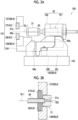
Figs. 2A and 2B are cross-sectional views showing a state when a nozzle has sealed a metal pipe material. -
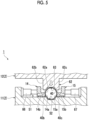
Fig. 3 is a cross-sectional view showing a forming process using a forming tool. -
Fig. 4 is a schematic configuration view showing a configuration of a divided restriction member. -
Fig. 5 is a cross-sectional view showing a state of forming by the forming tool. -
Fig. 6 is a cross-sectional view showing a state of forming by the forming tool. -
Fig. 7 is a cross-sectional view showing a state of forming by the forming tool. -
Figs. 8A and 8B are enlarged cross-sectional views showing a state where a restriction member restricts a planned flange portion. - Hereinafter, a preferred embodiment of the present disclosure will be described with reference to the drawings. In addition, in the respective drawings, the same portions or corresponding portions are designated by the same reference signs, and duplicated descriptions will not be repeated.
-
Fig. 1 is a schematic configuration view of a formingdevice 1 according to the present embodiment. As shown inFig. 1 , the formingdevice 1 is a device that forms a metal pipe having a hollow shape by blow forming. In the present embodiment, the formingdevice 1 is installed on a horizontal plane. The formingdevice 1 includes a forming tool (forming die) 2, adrive mechanism 3, a holding unit 4, aheating unit 5, afluid supply unit 6, acooling unit 7, and acontrol unit 8. In addition, in the present specification, a metal pipe material 40 (metal material) refers to a hollow article before completion of the forming by the formingdevice 1. Themetal pipe material 40 is a steel-type pipe material that can be hardened. Additionally, in the horizontal direction, a direction in which themetal pipe material 40 extends during forming may be referred to as a "longitudinal direction", and a direction perpendicular to the longitudinal direction may be referred to as a "width direction". - The forming
tool 2 is a die that forms a metal pipe 140 from themetal pipe material 40, and includes alower die 11 and anupper die 12 that face each other in a vertical direction. Thelower die 11 and theupper die 12 are made of steel blocks. Each of thelower die 11 and theupper die 12 is provided with a recessed portion in which themetal pipe material 40 is accommodated. With thelower die 11 and theupper die 12 in close contact with each other (die closed state), respective recessed portions thereof form a space having a target shape in which the metal pipe material is to be formed. Therefore, a surface of each of the recessed portions serves as a forming surface of the formingtool 2. Thelower die 11 is fixed to abase stage 13 via a die holder or the like. Theupper die 12 is fixed to a slide of thedrive mechanism 3 via a die holder or the like. - The
drive mechanism 3 is a mechanism that moves at least one of thelower die 11 and theupper die 12. InFig. 1 , thedrive mechanism 3 has a configuration in which only theupper die 12 is moved. Thedrive mechanism 3 includes aslide 21 that moves theupper die 12 such that thelower die 11 and theupper die 12 are joined together, and a pull-back cylinder 22 serving as an actuator that generates a force for pulling theslide 21 upward, amain cylinder 23 serving as a drive source that downward-pressurizes theslide 21, and adrive source 24 that applies a driving force to themain cylinder 23. - The holding unit 4 is a mechanism that holds the
metal pipe material 40 disposed between thelower die 11 and theupper die 12. The holding unit 4 includes a lower electrode 26 and an upper electrode 27 that hold themetal pipe material 40 on one end side in the longitudinal direction of the formingtool 2, and a lower electrode 26 and an upper electrode 27 that holds themetal pipe material 40 on the other end side in the longitudinal direction of the formingtool 2. The lower electrodes 26 and the upper electrodes 27 on both sides in the longitudinal direction hold themetal pipe material 40 by sandwiching vicinities of the end portions of themetal pipe material 40 from the vertical direction. In addition, groove portions having a shape corresponding to an outer peripheral surface of themetal pipe material 40 are formed on an upper surface of the lower electrode 26 and a lower surface of the upper electrode 27. The lower electrode 26 and the upper electrode 27 are provided with drive mechanisms (not shown) and are movable independently in the vertical direction. - The
heating unit 5 heats themetal pipe material 40. Theheating unit 5 is a mechanism that heats themetal pipe material 40 by energizing themetal pipe material 40. Theheating unit 5 heats themetal pipe material 40 in a state in which themetal pipe material 40 is spaced apart from thelower die 11 and theupper die 12 between thelower die 11 and theupper die 12. Theheating unit 5 includes the lower electrodes 26 and the upper electrodes 27 on both sides in the longitudinal direction as described above, and apower supply 28 that causes a current to flow through themetal pipe material 40 via the electrodes 26 and 27. In addition, the heating unit may be disposed in a preceding process of the formingdevice 1 and may perform heating externally. - The
fluid supply unit 6 is a mechanism that supplies a high-pressure fluid into themetal pipe material 40 held between thelower die 11 and theupper die 12. Thefluid supply unit 6 supplies the high-pressure fluid into themetal pipe material 40 that has been brought into a high-temperature state by being heated by theheating unit 5 and expands themetal pipe material 40. Thefluid supply unit 6 is provided on both end sides of the formingtool 2 in the longitudinal direction. Thefluid supply unit 6 includes anozzle 31 that supplies a fluid from an opening portion of an end portion of themetal pipe material 40 to the inside of themetal pipe material 40, adrive mechanism 32 that moves thenozzle 31 forward and backward with respect to the opening portion of themetal pipe material 40, and asupply source 33 that supplies the high-pressure fluid into themetal pipe material 40 via thenozzle 31. Thedrive mechanism 32 causes thenozzle 31 to be brought into close contact with the end portion of themetal pipe material 40 in a state in which sealing performance is secured during fluid supply and exhaust, and causes thenozzle 31 to be spaced apart from the end portion of themetal pipe material 40 at other times. In addition, thefluid supply unit 6 may supply a gas such as high-pressure air or an inert gas as the fluid. Additionally, thefluid supply unit 6 may include theheating unit 5 together with the holding unit 4 having a mechanism that moves themetal pipe material 40 in the vertical direction as the same device. - Components of the holding unit 4, the
heating unit 5, and thefluid supply unit 6 may be configured as a unitized heating and expandingunit 150.Fig. 2A is a schematic side view showing the heating and expandingunit 150.Fig. 2B is a cross-sectional view showing a state when thenozzle 31 has sealed themetal pipe material 40. - As shown in
Fig. 2A , the heating and expandingunit 150 includes the above-described lower electrode 26 and upper electrode 27, anelectrode mounting unit 151 on which the electrodes 26 and 27 are mounted, the above-describednozzle 31 anddrive mechanism 32, an elevating unit 152, and aunit base 153. Theelectrode mounting unit 151 includes an elevatingframe 154 and electrode frames 156 and 157. The electrode frames 156 and 157 function as a part of a drive mechanism 60 that supports and moves each of the electrodes 26 and 27. Thedrive mechanism 32 drives thenozzle 31 and lifts and lowers together with theelectrode mounting unit 151. Thedrive mechanism 32 includes apiston 161 that holds thenozzle 31, and acylinder 162 that drives the piston. The elevating unit 152 includes an elevatingframe base 64 attached to an upper surface of theunit base 153, and an elevatingactuator 166 that applies an elevating operation to the elevatingframe 154 of theelectrode mounting unit 151 by the elevatingframe base 64. The elevatingframe base 64 includesguide portions frame 154 with respect to theunit base 153. The elevating unit 152 functions as a part of the drive mechanism 60 of the holding unit 4. The heating and expandingunit 150 includes a plurality of the unit bases 153 of which upper surfaces have different inclination angles, and is allowed to collectively change and adjust inclination angles of the lower electrode 26 and the upper electrode 27, thenozzle 31, theelectrode mounting unit 151, thedrive mechanism 32, and the elevating unit 152 by replacing the unit bases 153. - The
nozzle 31 is a cylindrical member into which the end portion of themetal pipe material 40 can be inserted. Thenozzle 31 is supported by thedrive mechanism 32 such that a center line of thenozzle 31 coincides with a reference line SL1. An inner diameter of afeed port 31a at an end portion of thenozzle 31 on the side of themetal pipe material 40 substantially coincides with an outer diameter of themetal pipe material 40 after expansion forming. In this state, thenozzle 31 supplies the high-pressure fluid from aninternal flow path 163 to themetal pipe material 40. Examples of the high-pressure fluid include a gas and the like. - Returning to
Fig. 1 , thecooling unit 7 is a mechanism for cooling the formingtool 2. By cooling the formingtool 2, thecooling unit 7 can rapidly cool themetal pipe material 40 when the expandedmetal pipe material 40 has come into contact with the forming surface of the formingtool 2. Thecooling unit 7 includes aflow path 36 formed inside thelower die 11 and theupper die 12, and awater circulation mechanism 37 that supplies cooling water to theflow path 36 and circulates the cooling water. - The
control unit 8 is a device that controls the entire formingdevice 1. Thecontrol unit 8 controls thedrive mechanism 3, the holding unit 4, theheating unit 5, thefluid supply unit 6, and thecooling unit 7. Thecontrol unit 8 repeatedly performs an operation of forming themetal pipe material 40 with the formingtool 2. - Specifically, the
control unit 8 controls, for example, a transport timing from a transport device such as a robot arm to dispose themetal pipe material 40 between thelower die 11 and theupper die 12 in an open state. Alternatively, thecontrol unit 8 may allow a worker to manually dispose themetal pipe material 40 between thelower die 11 and theupper die 12. Additionally, thecontrol unit 8 controls an actuator of the holding unit 4 and the like such that themetal pipe material 40 is supported by the lower electrodes 26 on both sides in the longitudinal direction, and then the upper electrodes 27 are lowered to sandwich themetal pipe material 40. Additionally, thecontrol unit 8 controls theheating unit 5 to energize and heat themetal pipe material 40. Accordingly, an axial current flows through themetal pipe material 40, and an electric resistance of themetal pipe material 40 itself causes themetal pipe material 40 itself to generate heat due to Joule heat. - The
control unit 8 controls thedrive mechanism 3 to lower theupper die 12 and bring theupper die 12 close to thelower die 11 to close the formingtool 2. On the other hand, thecontrol unit 8 controls thefluid supply unit 6 to seal the opening portions of both ends of themetal pipe material 40 with thenozzle 31 and supply the fluid. Accordingly, themetal pipe material 40 softened by heating expands and comes into contact with the forming surface of the formingtool 2. Then, themetal pipe material 40 is formed so as to follow a shape of the forming surface of the formingtool 2. In addition, in a case where a metal pipe with a flange is formed, a part of themetal pipe material 40 is made to enter a gap between thelower die 11 and theupper die 12, and then die closing is further performed to crush the entering part to form a flange portion. When themetal pipe material 40 comes into contact with the forming surface, quenching of themetal pipe material 40 is performed by being rapidly cooled with the formingtool 2 cooled by thecooling unit 7. - The detailed configuration of the forming
device 1 will be described with reference toFigs. 3 and4 . First, ametal pipe 41 formed by the formingtool 2 will be described with reference toFig. 7 . Themetal pipe 41 includes ahollow pipe portion 41a andflange portions pipe portion 41a has a rectangular tubular shape. However, a shape of thepipe portion 41a is not particularly limited and may be any shape depending on applications. Theflange portions metal pipe material 40 in the width direction with the dies 11 and 12. In themetal pipe material 40, locations that are planned to become theflange portions flange portions Fig. 6 ). Also in the following description, unless otherwise specified, a protrusion portion in themetal pipe 41 after completion of forming is referred to as a "flange portion". Further, in themetal pipe material 40 in a state before the completion of forming, a location planned to become the flange portion after the completion is referred to as a "planned flange portion". A shape of the "planned flange portion" changes depending on a degree of progress of forming. As shown inFig. 4 , the metal pipe material 40 (and the metal pipe 41) is curved so as to protrude to one side in the width direction when viewed from the vertical direction. - The shape of the
metal pipe material 40 is not particularly limited and is not limited to a shape curved at one location. For example, themetal pipe material 40 may have a complex shape that is curved at a plurality of locations, or may have a linear shape. - As shown in
Fig. 3 , thelower die 11 includes aplanar portion 51 expanding in the width direction, a recessedportion 52 formed at a central position in the width direction of theplanar portion 51, andsupport portions portion 52 is a portion that forms a lower portion of thepipe portion 41a of the metal pipe 41 (refer toFig. 7 ). In theplanar portion 51, both sides of the recessedportion 52 in the width direction are configured as forming surfaces for forming theflange portions Fig. 7 ). Thesupport portions planar portion 51. Thesupport portion 53 is a portion that supports arestriction member 14 on a lateral side, and thesupport portion 54 is a portion that supports arestriction member 15 on a lateral side. - The
upper die 12 includes aplanar portion 61 expanding in the width direction and a formingbody portion 62 protruding downward at a central position of theplanar portion 61 in the width direction. The formingbody portion 62 has a substantially rectangular cross-sectional shape extending downward from theplanar portion 61. The formingbody portion 62 includes a recessedportion 63 on alower surface 62a. The recessedportion 63 is a portion that forms an upper portion of thepipe portion 41a of the metal pipe 41 (refer toFig. 7 ). Thelower surface 62a of the formingbody portion 62 is configured as forming surfaces for forming theflange portions portion 63 in the width direction (refer toFig. 7 ). The formingbody portion 62 has side surfaces 62b and 62c on both sides in the width direction. - The
restriction member 14 on a lateral side is disposed on one side of themetal pipe material 40 in the width direction. Therestriction member 15 on a lateral side is disposed on the other side of themetal pipe material 40 in the width direction. Therestriction members metal pipe material 40 during forming. In a case where a deviation of themetal pipe material 40 in the width direction becomes equal to or larger than a predetermined amount, therestriction members restriction members restriction surfaces metal pipe material 40, on inner sides in the width direction. Side surfaces 14b and 15b disposed at positions outside the restriction surfaces 14a and 15a in the width direction are formed on upper sides of the restriction surfaces 14a and 15a. - The
restriction member 14 is connected to adrive mechanism 66 provided in thesupport portion 53 of thedie 11. Thedrive mechanism 66 extends inward in the width direction from thesupport portion 53 and is connected to therestriction member 14. Therestriction member 15 is connected to adrive mechanism 67 provided in thesupport portion 54 of thedie 11. Thedrive mechanism 67 extends inward in the width direction from thesupport portion 54 and is connected to therestriction member 15. Thedrive mechanisms restriction members drive mechanisms - As shown in
Fig. 4 , therestriction member 14 is divided into a plurality of pieces in the longitudinal direction of themetal pipe material 40 during forming. The plurality of dividedrestriction members 14 are provided withindividual drive mechanisms 66. In the example shown inFig. 4 , therestriction member 14 is divided into sixrestriction members 14A to 14F. In addition,drive mechanisms 66A to 66B are individually provided for each of therestriction members 14A to 14F. Therestriction member 15 is divided into a plurality of pieces in the longitudinal direction of themetal pipe material 40 during forming. The plurality of dividedrestriction members 15 are provided withindividual drive mechanisms 67. In the example shown inFig. 4 , therestriction member 15 is divided into sixrestriction members 15A to 15F. In addition, thedrive mechanisms 67A to 67B are individually provided for each of therestriction members 15A to 15F. - The plurality of divided
restriction members 14A to 14F and 15A to 15F are individually controlled. That is, thecontrol unit 8 transmits an individual control signal to each of thedrive mechanisms 66A to 66F and 67A to 67F provided in the plurality ofrestriction members 14A to 14F and 15A to 15F. Thecontrol unit 8 operates thedrive mechanisms 66A to 66F and 67A to 67F by various control systems such as position control, pressure control, or time control. In this manner, thecontrol unit 8 can individually control therestriction members 14A to 14F and 15A to 15F to be disposed at any desired timing and any desired position at each position in the longitudinal direction of themetal pipe material 40. Plain text: In this manner, thecontrol unit 8 can control therestriction members 14A to 14F and 15A to 15F in accordance with an optimal restriction amount, an optimal contact timing, and the like, depending on the position in the longitudinal direction of themetal pipe material 40. - Next, a procedure of forming by the forming
device 1 will be described with reference toFigs. 3 and5 to 7 . In the present embodiment, therestriction members metal pipe material 40 before forming (here, before expansion). Therestriction members tool 2 in the width direction at each timing. Accordingly, the restriction surfaces 14a and 15a of therestriction members tool 2 in the width direction. - First, as shown in
Fig. 3 , in an initial state of forming, the dies 11 and 12 and therestriction members metal pipe material 40. Thecontrol unit 8 heats themetal pipe material 40 in this state. Accordingly, it is possible to prevent therestriction members metal pipe material 40 due to an influence of thermal expansion or Lorentz force, and to prevent electrical leakage due to such contact. Next, as shown inFig. 5 , thecontrol unit 8 lowers the die 12 downward. In addition, thecontrol unit 8 controls thedrive mechanisms restriction members metal pipe material 40 is disposed to be deviated in the width direction from a central position in the initial state of forming is considered (refer to an imaginary line inFig. 3 ). In this case, therestriction surface 15a of therestriction member 15 is brought into contact with themetal pipe material 40 and is pressed to the central position, so that the deviation of themetal pipe material 40 is restricted. - In addition, as shown in
Fig. 5 , thecontrol unit 8 controls thefluid supply unit 6 to supply the fluid into themetal pipe material 40 to perform blow forming (primary blowing). The portions of the plannedflange portions metal pipe material 40 in the width direction expand so as to enter between theplanar portion 51 of thedie 11 and thelower surface 62a of thedie 12. Thecontrol unit 8 may move therestriction members flange portions control unit 8 may move therestriction members flange portions restriction members flange portions - Next, as shown in
Fig. 6 , thecontrol unit 8 further lowers the die 12 downward. The plannedflange portions metal pipe material 40 are further crushed between theplanar portion 51 of thedie 11 and thelower surface 62a of the die 12, so that dimensions thereof in the width direction gradually increase with lowering of thedie 12. Thecontrol unit 8 may further move therestriction members control unit 8 may move therestriction members flange portions flange portions flange portions restriction members - The
control unit 8 further lowers the die 12 downward so that the dies 11 and 12 are completely closed as shown inFig. 7 (bottom dead center). In this case, the plannedflange portions flange portions control unit 8 supplies the fluid to themetal pipe material 40 by thefluid supply unit 6. Accordingly, the formingdevice 1 completes themetal pipe 41 by forming thepipe portion 41a corresponding to the shape of the recessedportions 52 and 63 (secondary blowing). After this, thecontrol unit 8 moves the die 12 upward to open the die. - Next, operations and effects of the forming
device 1 according to the present embodiment will be described. - The forming
device 1 includes the formingtool 2 that forms themetal pipe 41, and therestriction members metal pipe material 40 during forming. Therefore, the formingtool 2 can perform forming while restricting the deviation of themetal pipe material 40 with therestriction members restriction members metal pipe material 40 during forming. Therefore, the dividedrestriction members 14A to 14F and 15A to 15F can restrict the deviation at each position in the longitudinal direction with a restriction amount and a contact timing suitable for each position. From the above, it is possible to reduce variations in size of theflange portions metal pipe 41 after forming. - In particular, in a case of the curved
metal pipe material 40 shown inFig. 4 , a curvature may be different, or a distribution of heat due to energization heating may be different, depending on the position in the longitudinal direction. Therefore, an appropriate restriction amount is different depending on the position in the longitudinal direction of themetal pipe material 40. Therefore, therestriction members 14A to 14F and 15A to 15F can restrict the deviation in an appropriate mode according to each position of the curved shape. - The plurality of divided
restriction members 14A to 14F and 15A to 15F may be individually controlled. Accordingly, the dividedrestriction members 14A to 14F and 15A to 15F are individually controlled such that a restriction amount and a contact timing suitable for each position are set at each position in the longitudinal direction. - The
restriction members metal pipe material 40 before forming. In this case, therestriction members metal pipe material 40 in a stage before forming. - A forming method is a forming method of forming the
metal pipe 41 with a flange from themetal pipe material 40, and includes a step of restricting the deviation of themetal pipe material 40 with therestriction members metal pipe 41, and in this step, the deviation of themetal pipe material 40 is restricted by therestriction members 14A to 14F and 15A to 15F divided into a plurality of pieces in the longitudinal direction of themetal pipe material 40 during the forming. - According to this forming method, it is possible to obtain operations and effects having the same meaning as that of the above-described forming
device 1. - The present disclosure is not limited to the above-described embodiment.
- In the above-described embodiment, the
restriction members metal pipe material 40 before the forming. However, instead of this, therestriction members flange portions flange portions restriction members flange portions flange portions flange portions - For example, as shown in
Fig. 8A , in a case where, for example, themetal pipe material 40 deviates to therestriction member 15 side so that the protrusion amount of the plannedflange portion 40c increases, therestriction member 15 may bring therestriction surface 15a into contact with the plannedflange portion 40c to suppress the protrusion of the plannedflange portion 40c. Accordingly, it is possible to prevent theflange portions Fig. 8B , when the protrusion amount of the plannedflange portion 40c is as planned or shorter than planned, therestriction member 15 retreats so as not to come into contact with the plannedflange portion 40c so that therestriction member 15 does not hinder the protrusion of the plannedflange portion 40c. - In the above-described embodiment, the restriction members are provided on both sides in the width direction. However, the restriction member may be provided on only one side in the width direction.
- In the above-described embodiment, the description has been made by using the forming tool adopted in the forming device for STAF as an example. However, the type of the forming device in which the forming tool according to the present disclosure is adopted is not particularly limited, and may be any type of the forming device that supplies a fluid to expand the metal pipe material.
- A forming device that forms a metal pipe with a flange from a metal pipe material, the forming device including a forming tool that forms the metal pipe; and a restriction member that restricts a deviation of the metal pipe material during forming, in which the restriction member is divided into a plurality of pieces in a longitudinal direction of the metal pipe material during forming.
- The forming device according to
Aspect 1, in which a plurality of the divided restriction members are individually controlled. - The forming device according to
Aspect - The forming device according to any one of
Aspects 1 to 3, in which the restriction member restricts a deviation of a planned flange portion that becomes a flange portion after completion. - A forming method of forming a metal pipe with a flange from a metal pipe material, the forming method including a step of restricting a deviation of the metal pipe material with a restriction member during forming of the metal pipe, in which in the step, the deviation of the metal pipe material is restricted by the restriction member divided into a plurality of pieces in a longitudinal direction of the metal pipe material during forming.
-
- 1 Forming device
- 2 Forming tool (forming die)
- 14, 15 Restriction member
- 14a, 15a Restriction surface
- 40 Metal pipe material
- 40b, 40c Planned flange portion
- 41b, 41c Flange portion
- 41 Metal pipe
Claims (5)
- A forming device that forms a metal pipe with a flange from a metal pipe material, the forming device comprising:a forming tool that forms the metal pipe; anda restriction member that restricts a deviation of the metal pipe material during forming,wherein the restriction member is divided into a plurality of pieces in a longitudinal direction of the metal pipe material during forming.
- The forming device according to claim 1,
wherein a plurality of the divided restriction members are individually controlled. - The forming device according to claim 1,
wherein the restriction member restricts a deviation of the metal pipe material before forming. - The forming device according to claim 1,
wherein the restriction member restricts a deviation of a planned flange portion that becomes a flange portion after completion. - A forming method of forming a metal pipe with a flange from a metal pipe material, the forming method comprising:a step of restricting a deviation of the metal pipe material with a restriction member during forming of the metal pipe,wherein in the step, the deviation of the metal pipe material is restricted by the restriction member divided into a plurality of pieces in a longitudinal direction of the metal pipe material during forming.
Applications Claiming Priority (2)
| Application Number | Priority Date | Filing Date | Title |
|---|---|---|---|
| JP2021191142 | 2021-11-25 | ||
| PCT/JP2022/041040 WO2023095584A1 (en) | 2021-11-25 | 2022-11-02 | Molding device and molding method |
Publications (2)
| Publication Number | Publication Date |
|---|---|
| EP4438196A1 true EP4438196A1 (en) | 2024-10-02 |
| EP4438196A4 EP4438196A4 (en) | 2025-03-19 |
Family
ID=86539347
Family Applications (1)
| Application Number | Title | Priority Date | Filing Date |
|---|---|---|---|
| EP22898368.0A Pending EP4438196A4 (en) | 2021-11-25 | 2022-11-02 | MOLDING DEVICE AND MOLDING METHOD |
Country Status (7)
| Country | Link |
|---|---|
| US (1) | US20240253103A1 (en) |
| EP (1) | EP4438196A4 (en) |
| JP (1) | JPWO2023095584A1 (en) |
| KR (1) | KR20240116448A (en) |
| CN (1) | CN117980086A (en) |
| CA (1) | CA3235296A1 (en) |
| WO (1) | WO2023095584A1 (en) |
Families Citing this family (1)
| Publication number | Priority date | Publication date | Assignee | Title |
|---|---|---|---|---|
| CN120001862B (en) * | 2025-03-10 | 2025-11-28 | 江阴标榜汽车部件股份有限公司 | A flat tube forming apparatus and forming method |
Family Cites Families (8)
| Publication number | Priority date | Publication date | Assignee | Title |
|---|---|---|---|---|
| JP3205105B2 (en) * | 1993-01-29 | 2001-09-04 | 株式会社チューブフォーミング | Manufacturing method of deformed curved pipe |
| DE19602490C2 (en) * | 1996-01-25 | 2002-07-18 | Huber & Bauer Gmbh | Device for hydroforming |
| JP2009220141A (en) | 2008-03-14 | 2009-10-01 | Marujun Co Ltd | Method and apparatus for manufacturing pipe product |
| KR102345212B1 (en) * | 2015-08-27 | 2021-12-30 | 스미도모쥬기가이고교 가부시키가이샤 | Molding device and molding method |
| JP6651415B2 (en) * | 2016-06-30 | 2020-02-19 | 住友重機械工業株式会社 | Molding equipment |
| EP3597323B1 (en) * | 2017-03-17 | 2022-08-03 | Sumitomo Heavy Industries, Ltd. | Molding device and molding method |
| JP6381090B1 (en) * | 2017-10-17 | 2018-08-29 | リンツリサーチエンジニアリング株式会社 | Forming method of flanged pipe material |
| CN111390007B (en) * | 2020-04-01 | 2020-12-11 | 哈尔滨工大海卓智能成形科技有限公司 | Liquid-filled lateral extrusion forming device and method |
-
2022
- 2022-11-02 WO PCT/JP2022/041040 patent/WO2023095584A1/en not_active Ceased
- 2022-11-02 CA CA3235296A patent/CA3235296A1/en active Pending
- 2022-11-02 EP EP22898368.0A patent/EP4438196A4/en active Pending
- 2022-11-02 KR KR1020247007609A patent/KR20240116448A/en active Pending
- 2022-11-02 JP JP2023563594A patent/JPWO2023095584A1/ja active Pending
- 2022-11-02 CN CN202280060975.6A patent/CN117980086A/en active Pending
-
2024
- 2024-04-09 US US18/630,979 patent/US20240253103A1/en active Pending
Also Published As
| Publication number | Publication date |
|---|---|
| JPWO2023095584A1 (en) | 2023-06-01 |
| KR20240116448A (en) | 2024-07-29 |
| CN117980086A (en) | 2024-05-03 |
| US20240253103A1 (en) | 2024-08-01 |
| CA3235296A1 (en) | 2023-06-01 |
| WO2023095584A1 (en) | 2023-06-01 |
| EP4438196A4 (en) | 2025-03-19 |
Similar Documents
| Publication | Publication Date | Title |
|---|---|---|
| CN107921510A (en) | Molding machine and forming method | |
| US20240253103A1 (en) | Forming device and forming method | |
| US12502704B2 (en) | Forming device and metal pipe | |
| EP4403278A1 (en) | Molding device | |
| EP4292728B1 (en) | Molding device and metal pipe | |
| US12358037B2 (en) | Forming device and forming method | |
| EP4400228A1 (en) | Molding device | |
| US20250222508A1 (en) | Forming device | |
| US20260084200A1 (en) | Forming device | |
| JP7303718B2 (en) | Metal pipe material for molding equipment and blow molding | |
| EP4609963A1 (en) | Molding device and metal member | |
| CA3162758C (en) | Forming device and forming method | |
| EP4631642A1 (en) | Molding system | |
| EP4353377A1 (en) | Forming system, electric heating system, electrode, forming device, and support device | |
| KR20260048184A (en) | Forming device, forming system, and metal pipe |
Legal Events
| Date | Code | Title | Description |
|---|---|---|---|
| STAA | Information on the status of an ep patent application or granted ep patent |
Free format text: STATUS: THE INTERNATIONAL PUBLICATION HAS BEEN MADE |
|
| PUAI | Public reference made under article 153(3) epc to a published international application that has entered the european phase |
Free format text: ORIGINAL CODE: 0009012 |
|
| STAA | Information on the status of an ep patent application or granted ep patent |
Free format text: STATUS: REQUEST FOR EXAMINATION WAS MADE |
|
| 17P | Request for examination filed |
Effective date: 20240415 |
|
| AK | Designated contracting states |
Kind code of ref document: A1 Designated state(s): AL AT BE BG CH CY CZ DE DK EE ES FI FR GB GR HR HU IE IS IT LI LT LU LV MC ME MK MT NL NO PL PT RO RS SE SI SK SM TR |
|
| DAV | Request for validation of the european patent (deleted) | ||
| DAX | Request for extension of the european patent (deleted) | ||
| STAA | Information on the status of an ep patent application or granted ep patent |
Free format text: STATUS: EXAMINATION IS IN PROGRESS |
|
| A4 | Supplementary search report drawn up and despatched |
Effective date: 20250213 |
|
| RIC1 | Information provided on ipc code assigned before grant |
Ipc: B21D 24/10 20060101ALI20250207BHEP Ipc: B21D 26/033 20110101ALI20250207BHEP Ipc: B21D 19/08 20060101ALI20250207BHEP Ipc: B21D 26/035 20110101AFI20250207BHEP |
|
| 17Q | First examination report despatched |
Effective date: 20250311 |