EP4438011A1 - Expandable footprint implant - Google Patents
Expandable footprint implant Download PDFInfo
- Publication number
- EP4438011A1 EP4438011A1 EP24164340.2A EP24164340A EP4438011A1 EP 4438011 A1 EP4438011 A1 EP 4438011A1 EP 24164340 A EP24164340 A EP 24164340A EP 4438011 A1 EP4438011 A1 EP 4438011A1
- Authority
- EP
- European Patent Office
- Prior art keywords
- central
- actuator
- ramps
- implant
- rear plate
- Prior art date
- Legal status (The legal status is an assumption and is not a legal conclusion. Google has not performed a legal analysis and makes no representation as to the accuracy of the status listed.)
- Granted
Links
Images




Classifications
-
- A—HUMAN NECESSITIES
- A61—MEDICAL OR VETERINARY SCIENCE; HYGIENE
- A61F—FILTERS IMPLANTABLE INTO BLOOD VESSELS; PROSTHESES; DEVICES PROVIDING PATENCY TO, OR PREVENTING COLLAPSING OF, TUBULAR STRUCTURES OF THE BODY, e.g. STENTS; ORTHOPAEDIC, NURSING OR CONTRACEPTIVE DEVICES; FOMENTATION; TREATMENT OR PROTECTION OF EYES OR EARS; BANDAGES, DRESSINGS OR ABSORBENT PADS; FIRST-AID KITS
- A61F2/00—Filters implantable into blood vessels; Prostheses, i.e. artificial substitutes or replacements for parts of the body; Appliances for connecting them with the body; Devices providing patency to, or preventing collapsing of, tubular structures of the body, e.g. stents
- A61F2/02—Prostheses implantable into the body
- A61F2/30—Joints
- A61F2/44—Joints for the spine, e.g. vertebrae or spinal discs
- A61F2/4455—Joints for the spine, e.g. vertebrae or spinal discs for the fusion of spinal bodies, e.g. intervertebral fusion of adjacent spinal bodies, e.g. fusion cages
-
- A—HUMAN NECESSITIES
- A61—MEDICAL OR VETERINARY SCIENCE; HYGIENE
- A61F—FILTERS IMPLANTABLE INTO BLOOD VESSELS; PROSTHESES; DEVICES PROVIDING PATENCY TO, OR PREVENTING COLLAPSING OF, TUBULAR STRUCTURES OF THE BODY, e.g. STENTS; ORTHOPAEDIC, NURSING OR CONTRACEPTIVE DEVICES; FOMENTATION; TREATMENT OR PROTECTION OF EYES OR EARS; BANDAGES, DRESSINGS OR ABSORBENT PADS; FIRST-AID KITS
- A61F2/00—Filters implantable into blood vessels; Prostheses, i.e. artificial substitutes or replacements for parts of the body; Appliances for connecting them with the body; Devices providing patency to, or preventing collapsing of, tubular structures of the body, e.g. stents
- A61F2/02—Prostheses implantable into the body
- A61F2/30—Joints
- A61F2/44—Joints for the spine, e.g. vertebrae or spinal discs
- A61F2/4455—Joints for the spine, e.g. vertebrae or spinal discs for the fusion of spinal bodies, e.g. intervertebral fusion of adjacent spinal bodies, e.g. fusion cages
- A61F2/447—Joints for the spine, e.g. vertebrae or spinal discs for the fusion of spinal bodies, e.g. intervertebral fusion of adjacent spinal bodies, e.g. fusion cages substantially parallelepipedal, e.g. having a rectangular or trapezoidal cross-section
-
- A—HUMAN NECESSITIES
- A61—MEDICAL OR VETERINARY SCIENCE; HYGIENE
- A61F—FILTERS IMPLANTABLE INTO BLOOD VESSELS; PROSTHESES; DEVICES PROVIDING PATENCY TO, OR PREVENTING COLLAPSING OF, TUBULAR STRUCTURES OF THE BODY, e.g. STENTS; ORTHOPAEDIC, NURSING OR CONTRACEPTIVE DEVICES; FOMENTATION; TREATMENT OR PROTECTION OF EYES OR EARS; BANDAGES, DRESSINGS OR ABSORBENT PADS; FIRST-AID KITS
- A61F2/00—Filters implantable into blood vessels; Prostheses, i.e. artificial substitutes or replacements for parts of the body; Appliances for connecting them with the body; Devices providing patency to, or preventing collapsing of, tubular structures of the body, e.g. stents
- A61F2/02—Prostheses implantable into the body
- A61F2/30—Joints
- A61F2002/30001—Additional features of subject-matter classified in A61F2/28, A61F2/30 and subgroups thereof
- A61F2002/30316—The prosthesis having different structural features at different locations within the same prosthesis; Connections between prosthetic parts; Special structural features of bone or joint prostheses not otherwise provided for
- A61F2002/30329—Connections or couplings between prosthetic parts, e.g. between modular parts; Connecting elements
- A61F2002/30331—Connections or couplings between prosthetic parts, e.g. between modular parts; Connecting elements made by longitudinally pushing a protrusion into a complementarily-shaped recess, e.g. held by friction fit
-
- A—HUMAN NECESSITIES
- A61—MEDICAL OR VETERINARY SCIENCE; HYGIENE
- A61F—FILTERS IMPLANTABLE INTO BLOOD VESSELS; PROSTHESES; DEVICES PROVIDING PATENCY TO, OR PREVENTING COLLAPSING OF, TUBULAR STRUCTURES OF THE BODY, e.g. STENTS; ORTHOPAEDIC, NURSING OR CONTRACEPTIVE DEVICES; FOMENTATION; TREATMENT OR PROTECTION OF EYES OR EARS; BANDAGES, DRESSINGS OR ABSORBENT PADS; FIRST-AID KITS
- A61F2/00—Filters implantable into blood vessels; Prostheses, i.e. artificial substitutes or replacements for parts of the body; Appliances for connecting them with the body; Devices providing patency to, or preventing collapsing of, tubular structures of the body, e.g. stents
- A61F2/02—Prostheses implantable into the body
- A61F2/30—Joints
- A61F2002/30001—Additional features of subject-matter classified in A61F2/28, A61F2/30 and subgroups thereof
- A61F2002/30316—The prosthesis having different structural features at different locations within the same prosthesis; Connections between prosthetic parts; Special structural features of bone or joint prostheses not otherwise provided for
- A61F2002/30329—Connections or couplings between prosthetic parts, e.g. between modular parts; Connecting elements
- A61F2002/30383—Connections or couplings between prosthetic parts, e.g. between modular parts; Connecting elements made by laterally inserting a protrusion, e.g. a rib into a complementarily-shaped groove
- A61F2002/30387—Dovetail connection
-
- A—HUMAN NECESSITIES
- A61—MEDICAL OR VETERINARY SCIENCE; HYGIENE
- A61F—FILTERS IMPLANTABLE INTO BLOOD VESSELS; PROSTHESES; DEVICES PROVIDING PATENCY TO, OR PREVENTING COLLAPSING OF, TUBULAR STRUCTURES OF THE BODY, e.g. STENTS; ORTHOPAEDIC, NURSING OR CONTRACEPTIVE DEVICES; FOMENTATION; TREATMENT OR PROTECTION OF EYES OR EARS; BANDAGES, DRESSINGS OR ABSORBENT PADS; FIRST-AID KITS
- A61F2/00—Filters implantable into blood vessels; Prostheses, i.e. artificial substitutes or replacements for parts of the body; Appliances for connecting them with the body; Devices providing patency to, or preventing collapsing of, tubular structures of the body, e.g. stents
- A61F2/02—Prostheses implantable into the body
- A61F2/30—Joints
- A61F2002/30001—Additional features of subject-matter classified in A61F2/28, A61F2/30 and subgroups thereof
- A61F2002/30316—The prosthesis having different structural features at different locations within the same prosthesis; Connections between prosthetic parts; Special structural features of bone or joint prostheses not otherwise provided for
- A61F2002/30329—Connections or couplings between prosthetic parts, e.g. between modular parts; Connecting elements
- A61F2002/30383—Connections or couplings between prosthetic parts, e.g. between modular parts; Connecting elements made by laterally inserting a protrusion, e.g. a rib into a complementarily-shaped groove
- A61F2002/3039—Connections or couplings between prosthetic parts, e.g. between modular parts; Connecting elements made by laterally inserting a protrusion, e.g. a rib into a complementarily-shaped groove with possibility of relative movement of the rib within the groove
- A61F2002/30398—Sliding
-
- A—HUMAN NECESSITIES
- A61—MEDICAL OR VETERINARY SCIENCE; HYGIENE
- A61F—FILTERS IMPLANTABLE INTO BLOOD VESSELS; PROSTHESES; DEVICES PROVIDING PATENCY TO, OR PREVENTING COLLAPSING OF, TUBULAR STRUCTURES OF THE BODY, e.g. STENTS; ORTHOPAEDIC, NURSING OR CONTRACEPTIVE DEVICES; FOMENTATION; TREATMENT OR PROTECTION OF EYES OR EARS; BANDAGES, DRESSINGS OR ABSORBENT PADS; FIRST-AID KITS
- A61F2/00—Filters implantable into blood vessels; Prostheses, i.e. artificial substitutes or replacements for parts of the body; Appliances for connecting them with the body; Devices providing patency to, or preventing collapsing of, tubular structures of the body, e.g. stents
- A61F2/02—Prostheses implantable into the body
- A61F2/30—Joints
- A61F2002/30001—Additional features of subject-matter classified in A61F2/28, A61F2/30 and subgroups thereof
- A61F2002/30316—The prosthesis having different structural features at different locations within the same prosthesis; Connections between prosthetic parts; Special structural features of bone or joint prostheses not otherwise provided for
- A61F2002/30329—Connections or couplings between prosthetic parts, e.g. between modular parts; Connecting elements
- A61F2002/30405—Connections or couplings between prosthetic parts, e.g. between modular parts; Connecting elements made by screwing complementary threads machined on the parts themselves
-
- A—HUMAN NECESSITIES
- A61—MEDICAL OR VETERINARY SCIENCE; HYGIENE
- A61F—FILTERS IMPLANTABLE INTO BLOOD VESSELS; PROSTHESES; DEVICES PROVIDING PATENCY TO, OR PREVENTING COLLAPSING OF, TUBULAR STRUCTURES OF THE BODY, e.g. STENTS; ORTHOPAEDIC, NURSING OR CONTRACEPTIVE DEVICES; FOMENTATION; TREATMENT OR PROTECTION OF EYES OR EARS; BANDAGES, DRESSINGS OR ABSORBENT PADS; FIRST-AID KITS
- A61F2/00—Filters implantable into blood vessels; Prostheses, i.e. artificial substitutes or replacements for parts of the body; Appliances for connecting them with the body; Devices providing patency to, or preventing collapsing of, tubular structures of the body, e.g. stents
- A61F2/02—Prostheses implantable into the body
- A61F2/30—Joints
- A61F2002/30001—Additional features of subject-matter classified in A61F2/28, A61F2/30 and subgroups thereof
- A61F2002/30316—The prosthesis having different structural features at different locations within the same prosthesis; Connections between prosthetic parts; Special structural features of bone or joint prostheses not otherwise provided for
- A61F2002/30329—Connections or couplings between prosthetic parts, e.g. between modular parts; Connecting elements
- A61F2002/30476—Connections or couplings between prosthetic parts, e.g. between modular parts; Connecting elements locked by an additional locking mechanism
- A61F2002/30495—Connections or couplings between prosthetic parts, e.g. between modular parts; Connecting elements locked by an additional locking mechanism using a locking ring
-
- A—HUMAN NECESSITIES
- A61—MEDICAL OR VETERINARY SCIENCE; HYGIENE
- A61F—FILTERS IMPLANTABLE INTO BLOOD VESSELS; PROSTHESES; DEVICES PROVIDING PATENCY TO, OR PREVENTING COLLAPSING OF, TUBULAR STRUCTURES OF THE BODY, e.g. STENTS; ORTHOPAEDIC, NURSING OR CONTRACEPTIVE DEVICES; FOMENTATION; TREATMENT OR PROTECTION OF EYES OR EARS; BANDAGES, DRESSINGS OR ABSORBENT PADS; FIRST-AID KITS
- A61F2/00—Filters implantable into blood vessels; Prostheses, i.e. artificial substitutes or replacements for parts of the body; Appliances for connecting them with the body; Devices providing patency to, or preventing collapsing of, tubular structures of the body, e.g. stents
- A61F2/02—Prostheses implantable into the body
- A61F2/30—Joints
- A61F2002/30001—Additional features of subject-matter classified in A61F2/28, A61F2/30 and subgroups thereof
- A61F2002/30316—The prosthesis having different structural features at different locations within the same prosthesis; Connections between prosthetic parts; Special structural features of bone or joint prostheses not otherwise provided for
- A61F2002/30329—Connections or couplings between prosthetic parts, e.g. between modular parts; Connecting elements
- A61F2002/30476—Connections or couplings between prosthetic parts, e.g. between modular parts; Connecting elements locked by an additional locking mechanism
- A61F2002/30507—Connections or couplings between prosthetic parts, e.g. between modular parts; Connecting elements locked by an additional locking mechanism using a threaded locking member, e.g. a locking screw or a set screw
-
- A—HUMAN NECESSITIES
- A61—MEDICAL OR VETERINARY SCIENCE; HYGIENE
- A61F—FILTERS IMPLANTABLE INTO BLOOD VESSELS; PROSTHESES; DEVICES PROVIDING PATENCY TO, OR PREVENTING COLLAPSING OF, TUBULAR STRUCTURES OF THE BODY, e.g. STENTS; ORTHOPAEDIC, NURSING OR CONTRACEPTIVE DEVICES; FOMENTATION; TREATMENT OR PROTECTION OF EYES OR EARS; BANDAGES, DRESSINGS OR ABSORBENT PADS; FIRST-AID KITS
- A61F2/00—Filters implantable into blood vessels; Prostheses, i.e. artificial substitutes or replacements for parts of the body; Appliances for connecting them with the body; Devices providing patency to, or preventing collapsing of, tubular structures of the body, e.g. stents
- A61F2/02—Prostheses implantable into the body
- A61F2/30—Joints
- A61F2002/30001—Additional features of subject-matter classified in A61F2/28, A61F2/30 and subgroups thereof
- A61F2002/30316—The prosthesis having different structural features at different locations within the same prosthesis; Connections between prosthetic parts; Special structural features of bone or joint prostheses not otherwise provided for
- A61F2002/30329—Connections or couplings between prosthetic parts, e.g. between modular parts; Connecting elements
- A61F2002/30476—Connections or couplings between prosthetic parts, e.g. between modular parts; Connecting elements locked by an additional locking mechanism
- A61F2002/30514—Connections or couplings between prosthetic parts, e.g. between modular parts; Connecting elements locked by an additional locking mechanism using a locking washer
-
- A—HUMAN NECESSITIES
- A61—MEDICAL OR VETERINARY SCIENCE; HYGIENE
- A61F—FILTERS IMPLANTABLE INTO BLOOD VESSELS; PROSTHESES; DEVICES PROVIDING PATENCY TO, OR PREVENTING COLLAPSING OF, TUBULAR STRUCTURES OF THE BODY, e.g. STENTS; ORTHOPAEDIC, NURSING OR CONTRACEPTIVE DEVICES; FOMENTATION; TREATMENT OR PROTECTION OF EYES OR EARS; BANDAGES, DRESSINGS OR ABSORBENT PADS; FIRST-AID KITS
- A61F2/00—Filters implantable into blood vessels; Prostheses, i.e. artificial substitutes or replacements for parts of the body; Appliances for connecting them with the body; Devices providing patency to, or preventing collapsing of, tubular structures of the body, e.g. stents
- A61F2/02—Prostheses implantable into the body
- A61F2/30—Joints
- A61F2002/30001—Additional features of subject-matter classified in A61F2/28, A61F2/30 and subgroups thereof
- A61F2002/30316—The prosthesis having different structural features at different locations within the same prosthesis; Connections between prosthetic parts; Special structural features of bone or joint prostheses not otherwise provided for
- A61F2002/30329—Connections or couplings between prosthetic parts, e.g. between modular parts; Connecting elements
- A61F2002/30476—Connections or couplings between prosthetic parts, e.g. between modular parts; Connecting elements locked by an additional locking mechanism
- A61F2002/30515—Connections or couplings between prosthetic parts, e.g. between modular parts; Connecting elements locked by an additional locking mechanism using a locking wedge or block
-
- A—HUMAN NECESSITIES
- A61—MEDICAL OR VETERINARY SCIENCE; HYGIENE
- A61F—FILTERS IMPLANTABLE INTO BLOOD VESSELS; PROSTHESES; DEVICES PROVIDING PATENCY TO, OR PREVENTING COLLAPSING OF, TUBULAR STRUCTURES OF THE BODY, e.g. STENTS; ORTHOPAEDIC, NURSING OR CONTRACEPTIVE DEVICES; FOMENTATION; TREATMENT OR PROTECTION OF EYES OR EARS; BANDAGES, DRESSINGS OR ABSORBENT PADS; FIRST-AID KITS
- A61F2/00—Filters implantable into blood vessels; Prostheses, i.e. artificial substitutes or replacements for parts of the body; Appliances for connecting them with the body; Devices providing patency to, or preventing collapsing of, tubular structures of the body, e.g. stents
- A61F2/02—Prostheses implantable into the body
- A61F2/30—Joints
- A61F2002/30001—Additional features of subject-matter classified in A61F2/28, A61F2/30 and subgroups thereof
- A61F2002/30316—The prosthesis having different structural features at different locations within the same prosthesis; Connections between prosthetic parts; Special structural features of bone or joint prostheses not otherwise provided for
- A61F2002/30535—Special structural features of bone or joint prostheses not otherwise provided for
- A61F2002/30537—Special structural features of bone or joint prostheses not otherwise provided for adjustable
-
- A—HUMAN NECESSITIES
- A61—MEDICAL OR VETERINARY SCIENCE; HYGIENE
- A61F—FILTERS IMPLANTABLE INTO BLOOD VESSELS; PROSTHESES; DEVICES PROVIDING PATENCY TO, OR PREVENTING COLLAPSING OF, TUBULAR STRUCTURES OF THE BODY, e.g. STENTS; ORTHOPAEDIC, NURSING OR CONTRACEPTIVE DEVICES; FOMENTATION; TREATMENT OR PROTECTION OF EYES OR EARS; BANDAGES, DRESSINGS OR ABSORBENT PADS; FIRST-AID KITS
- A61F2/00—Filters implantable into blood vessels; Prostheses, i.e. artificial substitutes or replacements for parts of the body; Appliances for connecting them with the body; Devices providing patency to, or preventing collapsing of, tubular structures of the body, e.g. stents
- A61F2/02—Prostheses implantable into the body
- A61F2/30—Joints
- A61F2002/30001—Additional features of subject-matter classified in A61F2/28, A61F2/30 and subgroups thereof
- A61F2002/30316—The prosthesis having different structural features at different locations within the same prosthesis; Connections between prosthetic parts; Special structural features of bone or joint prostheses not otherwise provided for
- A61F2002/30535—Special structural features of bone or joint prostheses not otherwise provided for
- A61F2002/30537—Special structural features of bone or joint prostheses not otherwise provided for adjustable
- A61F2002/30545—Special structural features of bone or joint prostheses not otherwise provided for adjustable for adjusting a diameter
-
- A—HUMAN NECESSITIES
- A61—MEDICAL OR VETERINARY SCIENCE; HYGIENE
- A61F—FILTERS IMPLANTABLE INTO BLOOD VESSELS; PROSTHESES; DEVICES PROVIDING PATENCY TO, OR PREVENTING COLLAPSING OF, TUBULAR STRUCTURES OF THE BODY, e.g. STENTS; ORTHOPAEDIC, NURSING OR CONTRACEPTIVE DEVICES; FOMENTATION; TREATMENT OR PROTECTION OF EYES OR EARS; BANDAGES, DRESSINGS OR ABSORBENT PADS; FIRST-AID KITS
- A61F2/00—Filters implantable into blood vessels; Prostheses, i.e. artificial substitutes or replacements for parts of the body; Appliances for connecting them with the body; Devices providing patency to, or preventing collapsing of, tubular structures of the body, e.g. stents
- A61F2/02—Prostheses implantable into the body
- A61F2/30—Joints
- A61F2002/30001—Additional features of subject-matter classified in A61F2/28, A61F2/30 and subgroups thereof
- A61F2002/30316—The prosthesis having different structural features at different locations within the same prosthesis; Connections between prosthetic parts; Special structural features of bone or joint prostheses not otherwise provided for
- A61F2002/30535—Special structural features of bone or joint prostheses not otherwise provided for
- A61F2002/30537—Special structural features of bone or joint prostheses not otherwise provided for adjustable
- A61F2002/3055—Special structural features of bone or joint prostheses not otherwise provided for adjustable for adjusting length
-
- A—HUMAN NECESSITIES
- A61—MEDICAL OR VETERINARY SCIENCE; HYGIENE
- A61F—FILTERS IMPLANTABLE INTO BLOOD VESSELS; PROSTHESES; DEVICES PROVIDING PATENCY TO, OR PREVENTING COLLAPSING OF, TUBULAR STRUCTURES OF THE BODY, e.g. STENTS; ORTHOPAEDIC, NURSING OR CONTRACEPTIVE DEVICES; FOMENTATION; TREATMENT OR PROTECTION OF EYES OR EARS; BANDAGES, DRESSINGS OR ABSORBENT PADS; FIRST-AID KITS
- A61F2/00—Filters implantable into blood vessels; Prostheses, i.e. artificial substitutes or replacements for parts of the body; Appliances for connecting them with the body; Devices providing patency to, or preventing collapsing of, tubular structures of the body, e.g. stents
- A61F2/02—Prostheses implantable into the body
- A61F2/30—Joints
- A61F2002/30001—Additional features of subject-matter classified in A61F2/28, A61F2/30 and subgroups thereof
- A61F2002/30316—The prosthesis having different structural features at different locations within the same prosthesis; Connections between prosthetic parts; Special structural features of bone or joint prostheses not otherwise provided for
- A61F2002/30535—Special structural features of bone or joint prostheses not otherwise provided for
- A61F2002/30537—Special structural features of bone or joint prostheses not otherwise provided for adjustable
- A61F2002/30556—Special structural features of bone or joint prostheses not otherwise provided for adjustable for adjusting thickness
-
- A—HUMAN NECESSITIES
- A61—MEDICAL OR VETERINARY SCIENCE; HYGIENE
- A61F—FILTERS IMPLANTABLE INTO BLOOD VESSELS; PROSTHESES; DEVICES PROVIDING PATENCY TO, OR PREVENTING COLLAPSING OF, TUBULAR STRUCTURES OF THE BODY, e.g. STENTS; ORTHOPAEDIC, NURSING OR CONTRACEPTIVE DEVICES; FOMENTATION; TREATMENT OR PROTECTION OF EYES OR EARS; BANDAGES, DRESSINGS OR ABSORBENT PADS; FIRST-AID KITS
- A61F2/00—Filters implantable into blood vessels; Prostheses, i.e. artificial substitutes or replacements for parts of the body; Appliances for connecting them with the body; Devices providing patency to, or preventing collapsing of, tubular structures of the body, e.g. stents
- A61F2/02—Prostheses implantable into the body
- A61F2/30—Joints
- A61F2002/30001—Additional features of subject-matter classified in A61F2/28, A61F2/30 and subgroups thereof
- A61F2002/30316—The prosthesis having different structural features at different locations within the same prosthesis; Connections between prosthetic parts; Special structural features of bone or joint prostheses not otherwise provided for
- A61F2002/30535—Special structural features of bone or joint prostheses not otherwise provided for
- A61F2002/30579—Special structural features of bone or joint prostheses not otherwise provided for with mechanically expandable devices, e.g. fixation devices
-
- A—HUMAN NECESSITIES
- A61—MEDICAL OR VETERINARY SCIENCE; HYGIENE
- A61F—FILTERS IMPLANTABLE INTO BLOOD VESSELS; PROSTHESES; DEVICES PROVIDING PATENCY TO, OR PREVENTING COLLAPSING OF, TUBULAR STRUCTURES OF THE BODY, e.g. STENTS; ORTHOPAEDIC, NURSING OR CONTRACEPTIVE DEVICES; FOMENTATION; TREATMENT OR PROTECTION OF EYES OR EARS; BANDAGES, DRESSINGS OR ABSORBENT PADS; FIRST-AID KITS
- A61F2/00—Filters implantable into blood vessels; Prostheses, i.e. artificial substitutes or replacements for parts of the body; Appliances for connecting them with the body; Devices providing patency to, or preventing collapsing of, tubular structures of the body, e.g. stents
- A61F2/02—Prostheses implantable into the body
- A61F2/30—Joints
- A61F2/44—Joints for the spine, e.g. vertebrae or spinal discs
- A61F2002/449—Joints for the spine, e.g. vertebrae or spinal discs comprising multiple spinal implants located in different intervertebral spaces or in different vertebrae
-
- A—HUMAN NECESSITIES
- A61—MEDICAL OR VETERINARY SCIENCE; HYGIENE
- A61F—FILTERS IMPLANTABLE INTO BLOOD VESSELS; PROSTHESES; DEVICES PROVIDING PATENCY TO, OR PREVENTING COLLAPSING OF, TUBULAR STRUCTURES OF THE BODY, e.g. STENTS; ORTHOPAEDIC, NURSING OR CONTRACEPTIVE DEVICES; FOMENTATION; TREATMENT OR PROTECTION OF EYES OR EARS; BANDAGES, DRESSINGS OR ABSORBENT PADS; FIRST-AID KITS
- A61F2/00—Filters implantable into blood vessels; Prostheses, i.e. artificial substitutes or replacements for parts of the body; Appliances for connecting them with the body; Devices providing patency to, or preventing collapsing of, tubular structures of the body, e.g. stents
- A61F2/02—Prostheses implantable into the body
- A61F2/30—Joints
- A61F2/46—Special tools for implanting artificial joints
- A61F2/4603—Special tools for implanting artificial joints for insertion or extraction of endoprosthetic joints or of accessories thereof
- A61F2002/4625—Special tools for implanting artificial joints for insertion or extraction of endoprosthetic joints or of accessories thereof with relative movement between parts of the instrument during use
- A61F2002/4627—Special tools for implanting artificial joints for insertion or extraction of endoprosthetic joints or of accessories thereof with relative movement between parts of the instrument during use with linear motion along or rotating motion about the instrument axis or the implantation direction, e.g. telescopic, along a guiding rod, screwing inside the instrument
Definitions
- the present disclosure generally relates to devices and methods for promoting an intervertebral fusion, and more particularly relates to expandable fusion devices capable of being inserted between adjacent vertebrae to facilitate the fusion process and related systems and methods.
- intervertebral fusion devices for fusing one or more adjacent vertebral bodies.
- the intervertebral disc is first partially or fully removed.
- An intervertebral fusion device is then inserted between neighboring vertebrae to maintain normal disc spacing and restore spinal stability, thereby facilitating an intervertebral fusion.
- fusion devices and methodologies for accomplishing the intervertebral fusion may include solid bone implants, fusion devices which include a cage or other implant mechanism, which may be packed with bone and/or bone growth inducing substances, and expandable implants.
- fusion devices which include a cage or other implant mechanism, which may be packed with bone and/or bone growth inducing substances, and expandable implants.
- posterior implants may be implanted to provide disc height restoration.
- the implants may be installed between adjacent vertebral bodies in order to fuse the vertebral bodies together, thereby alleviating the associated pain.
- expandable intervertebral implants for example, for posterior spinal surgery may be used to treat a variety of patient indications.
- the expandable implants are configured to increase the overall footprint size after being inserted into the disc space while also adjusting the lordosis and overall height.
- the in-situ expandable footprint or surface area is configured to address the subsidence issue and in-situ adjustable lordosis is configured to address the sagittal balance issue.
- the intervertebral implant may be combined with a posterior stabilization system, for example, including pedicle screws and spinal rod(s) to further stabilize the spine.
- an expandable intervertebral implant includes a central drive assembly and left and right side assemblies.
- the central drive assembly includes a central drive screw positioned through a front plate, the central drive screw threadedly engaged to a central actuator, the central actuator coupled to a threaded sleeve, and the threaded sleeve positioned through a rear plate and threadedly engaged with a drive nut.
- the left and right side assemblies each include upper and lower endplates, a side actuator, and a front ramp. The side actuator and front ramp are slidably engaged with the upper and lower endplates. Rotation of the drive nut expands the implant in width and rotation of the drive screw expands the implant in height.
- the expandable intervertebral implant may include one or more of the following features.
- the drive nut may pull the threaded sleeve and central actuator toward the rear plate and push the left and right side portions outwards in width.
- the drive screw may pull the front ramp toward the central actuator which then expands the upper and lower endplates in height.
- the central actuator may include a tubular body with an inner bore and a pair of opposite wings configured to mate with the side actuators.
- the rear plate may include a pair of female horizontal ramps defined into top and bottom surfaces of the rear plate, and the side actuator may include a pair of horizontal male ramps configured to interface with the female horizontal ramps of the rear plate.
- the front plate may include a pair of female horizontal ramps defined into top and bottom surfaces of the front plate, and the front ramp may include a pair of male horizontal ramps configured to interface with the female horizontal ramps of the front plate.
- an expandable intervertebral implant includes a front plate having a central through bore, a central drive screw having an enlarged head and a threaded shaft positioned through the bore in the front plate, a central actuator having a tubular body with a through bore and a pair of opposed wings, the threaded shaft of the central drive screw threadedly engaged within one end of the bore of the central actuator, a rear plate having a central through bore, a threaded sleeve positioned through the bore in the rear plate and threadedly engaged with an opposite end of the bore of the central actuator, a drive nut threadedly engaged with the threaded sleeve, and left and right side assemblies each including upper and lower endplates, a side actuator, and a front ramp.
- the side actuator and front ramp are slidably engaged with the upper and lower endplates, the side actuator is slidably engaged with the rear plate and central actuator, and the front ramp is slidably engaged with the front plate.
- the expandable intervertebral implant may include one or more of the following features.
- the left and right side assemblies may have a laterally collapsed configuration having a first width and a laterally expanded configuration having a second width, and the left and right side assemblies may have a vertically collapsed configuration having a first height and a vertically expanded configuration having a second height.
- the pair of opposed wings may each define a female ramp configured to receive a corresponding male ramp from the side actuator.
- the pair of opposed wings may be angled distally toward the front plate.
- the rear plate may include a cylindrical ring projecting proximally.
- the cylindrical ring may define an outer threaded surface.
- the threaded sleeve may include a first proximal exterior threaded section configured to interface with inner threads in a bore of the drive nut, and a second distal exterior threaded section configured to interface with inner threads in the bore of central actuator.
- the central drive screw may be retained in the front plate with a retaining ring.
- the drive nut may be retained in the rear plate with a retaining sleeve.
- an expandable intervertebral implant includes a central drive assembly and a side assembly.
- the central drive assembly includes a front plate, a central drive screw, a central actuator, a threaded sleeve, a rear plate, and a drive nut aligned along a central longitudinal axis.
- the central drive screw is retained in the front plate.
- the central actuator is threadedly engaged with the central drive screw and the threaded sleeve.
- the threaded sleeve is retained in the rear plate and threadedly engaged with the drive nut.
- the side assembly includes upper and lower endplates, a side actuator, and a front ramp.
- the side actuator and front ramp are slidably engaged with the upper and lower endplates.
- the side actuator is slidably engaged with the rear plate and central actuator, and the front ramp is slidably engaged with the front plate.
- the expandable intervertebral implant may include one or more of the following features.
- the central drive screw may extend from a proximal end to a distal end where the distal end includes an enlarged head portion and the proximal end defines an instrument recess.
- the drive nut may define a central through bore and a proximal face of the drive nut may define an instrument recess different from the instrument recess of the central drive screw.
- the central drive screw may be located at a distal end of the implant and the drive nut may be located at a proximal end of the implant.
- the drive nut When actuated, the drive nut may pull the threaded sleeve and central actuator proximally, thereby causing an expansion in width.
- the central drive screw may pull the front plate toward the central actuator and pull the front ramp toward the side actuator, thereby causing an expansion in height.
- a method of assembling an expandable intervertebral implant may include one or more of the following steps in any suitable order: (1) placing two front ramps onto a front plate by aligning mating ramps or slides; (2) placing one side actuator onto a rear plate by aligning mating ramps or slides; (3) placing a central actuator onto the side actuator and placing a second side actuator onto the rear plate and the central actuator by aligning the ramps or slides; (4) assembling each of the left and right side assemblies by placing a lower endplate onto the side actuator and placing an upper endplate onto the side actuator; (5) placing the front ramp into both the lower and upper endplates; (6) inserting a threaded sleeve through the rear plate and into the central actuator; (7) placing a friction ring onto the drive nut; (8) threading the drive nut onto the threaded sleeve; (9) pressing a retaining sleeve into the rear plate to secure the drive nut; (10) placing a friction ring onto a central drive screw; (1
- a spinal fixation system includes an expandable intervertebral implant, a bone fastener, and a spinal rod attachable to the bone fastener.
- the expandable intervertebral implant comprising a central drive assembly and left and right side assemblies, the central drive assembly including a front plate, a central drive screw, a central actuator, a threaded sleeve, a rear plate, and a drive nut, and the left and right side assemblies each including upper and lower endplates, a side actuator, and a front ramp, wherein rotation of the drive nut is configured to expand the implant in width and rotation of the drive screw is configured to expand the implant in height.
- the spinal fixation system may include one or more of the following features.
- the expandable intervertebral implant may be configured to be installed through a transforaminal lumbar interbody fusion procedure.
- the bone fastener may include a threaded shaft and a tulip head.
- the bone fastener may be a polyaxial bone screw.
- the bone fastener may be a pedicle screw.
- the plurality of bone fasteners may be configured to be installed in vertebrae adjacent to the expandable intervertebral implant.
- the system may include a set of screws and rods configured to stabilize the spine.
- a spinal fixation system includes an expandable intervertebral implant comprising a central drive assembly and left and right side assemblies, and a posterior stabilization system.
- the central drive assembly includes a front plate having a central through bore, a central drive screw having an enlarged head and a threaded shaft positioned through the bore in the front plate, a central actuator having a tubular body with a through bore and a pair of opposed wings, the threaded shaft of the central drive screw threadedly engaged within one end of the bore of the central actuator, a rear plate having a central through bore, a threaded sleeve positioned through the bore in the rear plate and threadedly engaged with an opposite end of the bore of the central actuator, and a drive nut threadedly engaged with the threaded sleeve.
- the left and right side assemblies each include upper and lower endplates, a side actuator, and a front ramp,
- the spinal fixation system may include one or more of the following features.
- the posterior stabilization system may include a plurality of bone fasteners including a threaded shaft and a tulip head.
- the plurality of bone fasteners may be configured to be inserted into pedicles of adjacent vertebrae.
- the posterior stabilization system may include a spinal rod affixed to the tulip heads of the bone fasteners to stabilize a portion of the spine.
- Actuation of the drive nut may be configured to expand the intervertebral implant in width.
- Actuation of the central drive screw may be configured to expand the intervertebral implant in height in-situ.
- the method may further include expanding the implant in width by rotating the drive nut and expanding the implant in height by rotating the central drive screw.
- the implant may be expanded in width to increase an overall footprint size, thereby minimizing a potential for implant subsidence.
- the implant may be expanded in height in-situ to adjust lordosis.
- a first set of bone screws may be affixed to pedicles of the vertebrae, and a first spinal rod is connected therebetween, a second set of bone screw may be affixed to opposite pedicle of the vertebrae, and a second spinal rod is connected therebetween.
- a kit may include a plurality of implants of different sizes and configurations.
- the kit may further include one or more devices suitable for installing and/or removing the implants and systems described herein, such as insertion devices or drivers; one or more removal devices; and other tools and devices, which may be suitable for surgery.
- Embodiments of the disclosure are generally directed to devices, systems, and methods for intervertebral fusion and spine stabilization.
- expandable implants are configured to increase the overall footprint size after being inserted into the disc space while also adjusting the lordosis and overall height.
- the expandable implants may include one or more side assemblies configured to expand in width and in height. In doing so, the expansion addresses sagittal balance correction and subsidence issues.
- the intervertebral implant may be combined with a posterior stabilization system, for example, including pedicle screws and spinal rod(s) to further stabilize the spine.
- a spinal fusion is typically employed to eliminate pain caused by motion of degenerated disc material.
- a fusion device becomes permanently fixed within the intervertebral disc space.
- the expandable fusion device may be positioned between adjacent vertebral bodies in a collapsed position.
- the expandable fusion device is configured to expand in width and subsequently in height.
- the fusion device engages the endplates of the adjacent vertebral bodies and, in the installed position, maintains desired intervertebral disc spacing and restores spinal stability, thereby facilitating the intervertebral fusion.
- MIS Minimally invasive surgery
- the expandable fusion device can be configured to be placed down an endoscopic tube and into the surgical target site.
- the surgical site may be an intervertebral disc space situated between two adjacent vertebrae.
- the implant may be employed in any number of suitable orthopedic approaches and procedures, including but not limited to, anterior, posterior, lateral, anterolateral, or posterolateral approaches to the lumbar spine, cervical spine, or thoracic spine, as well as any non-spine application, such as treatment of bone fractures and the like.
- suitable orthopedic approaches and procedures including but not limited to, anterior, posterior, lateral, anterolateral, or posterolateral approaches to the lumbar spine, cervical spine, or thoracic spine, as well as any non-spine application, such as treatment of bone fractures and the like.
- Components of all of the devices disclosed herein may be manufactured of any suitable materials including metals (e.g., titanium), metal alloys (e.g., stainless steel, cobalt-chromium, and titanium alloys), ceramics, plastics, plastic composites, or polymeric materials (e.g., polyether ether ketone (PEEK), polyphenylene sulfone (PPSU), polysulfone (PSU), polycarbonate (PC), polyetherimide (PEI), polypropylene (PP), polyacetals, or mixtures or co-polymers thereof), and/or combinations thereof.
- the devices may include radiolucent and/or radiopaque materials.
- the components can also be machined and/or manufactured using any suitable techniques (e.g., 3D printing).
- FIGS. 1A-1C illustrate an expandable fusion device or implant 10 according to one embodiment.
- the expandable fusion device 10 may include left and right side portion assemblies 12, 14 configured to expand in width to increase the overall footprint of the device 10 and expand in height to correct disc height restoration, lordosis, and/or sagittal balance.
- the implant 10 may be suitable for a transforaminal lumbar interbody fusion (TLIF) through a posterior approach or other suitable surgical procedure.
- TLIF transforaminal lumbar interbody fusion
- the expandable fusion device 10 extends along a central longitudinal axis A between front and rear ends of the device 10.
- FIG. 1A shows the expandable fusion device 10 in a fully collapsed configuration with the left and right side portions 12, 14 collapsed in both width and height.
- FIG. 1B shows the expandable fusion device 10 in an expanded configuration with the left and right side portions 12, 14 expanded in width.
- FIG. 1C shows the expandable fusion device in a fully expanded configuration with the left and right side portions 12, 14 expanded in width and in height.
- references to the front and rear ends and left and right side portions 12, 14 are described with respect to the direction of placement into an intervertebral disc space with the front of the expandable fusion device 10 placed into the disc space first, followed by the rear of the expandable fusion device 10. These and other directional terms may be used herein for descriptive purposes and do not limit the orientation(s) in which the devices may be used.
- the implant 10 includes a first half or left side portion 12, a second half or right side portion 14, and a central drive assembly 16.
- the left and right side portion assemblies 12, 14 may each include upper and lower endplates 20, 22, a front ramp 24, and a side actuator 26.
- the central drive assembly 16 includes a central drive screw 30, a front plate 32, a central actuator 34, a rear plate 36, a central threaded sleeve 38, and a central drive nut 40 aligned along the central longitudinal axis A.
- the front plate 32 is operatively coupled to the front part of the first half or left side portion 12 and the second half or right side portion 14 and to the central drive screw 30.
- the rear plate 36 is operatively coupled to the rear part of the first half or left side portion 12 and the second half or right side portion 14 and to the central drive nut 40.
- the left and right side portions 12, 14 are expanded in width by the central drive nut 40.
- the upper and lower endplates 20, 22 are expanded in height by the central drive screw 30.
- the left and right side portions 12, 14 are controllable by the central drive nut 40 which is attached to the central threaded sleeve 38 and central actuator 34.
- the drive nut 40 pulls the threaded sleeve 38 and central actuator 34 toward the rear plate 36 and pushes the left and right side portions 12, 14 outwards with the uses of ramps or slides 70, 102, 132, 154, 156, 170.
- the front plate 32 is controllable by the central drive screw 30.
- the central drive screw 30 pulls the front plate 20 toward the central actuator 34 while also pulling the front ramps 24 toward the side actuators 26.
- Each side assembly 12, 14 has upper and lower endplates 20, 22, front ramp 24, and side actuator 26.
- the front ramp 24 is actuated while the drive screw 30 is turned. This pulls the front ramp 24 toward the side actuator 26 which then expands the top and bottom endplates 20, 22 up and down with mating ramps 142, 160, 168 on the front ramps 24 and side actuators 26.
- the central drive screw 30 extends from a proximal end 44 to a distal end 46.
- the distal end 46 may include an enlarged head portion 48 configured to be received in a bore 62 defined through the front plate 32.
- the enlarged head 48 may include a wide cylindrical head with a smooth outer surface at the distal end of the central drive screw 30.
- the proximal end 44 of the drive screw 30 may define an instrument recess 50 configured to receive an instrument, such as a driver, to rotate or actuate the drive screw 30.
- the instrument recess 50 may include a tri-lobe, hex, star, or other suitable recess configured to engage with a driver instrument to apply torque to the drive screw 30.
- the drive screw 30 may include a shaft with an exterior threaded portion 52 extending along its length.
- the exterior threads 52 may extend from the proximal end 44 to a location near the bottom of the enlarged head 48.
- the drive screw 30 is receivable through the bore 62 in the front plate 32 such that the enlarged head portion 48 of the drive screw 30 is receivable in the front plate 32.
- An optional friction ring 56 such as a polyether ether ketone (PEEK) ring, may be assembled onto the drive screw 30, for example, below the enlarged head 48, to increase friction or drag on the drive screw 30 during rotation.
- PEEK polyether ether ketone
- the central drive screw 30 is inserted into the front plate 32 and may be retained within the front plate 32 using a retaining ring 58.
- the drive screw 30 controls height expansion of the implant 10 when actuated.
- the retaining ring 58 may include a split ring with a plurality of inner and/or outer teeth 60 or various reliefs to allow the retaining ring 58 to compress and enter the bore 62 of the front plate 32 and engage an internal groove.
- the retaining ring 60 may include two slots, for example, to be engaged with an instrument to aid insertion and removal of the retaining ring 58.
- the front plate 32 defines a central bore 62 therethrough configured to receive drive screw 30.
- the axis of bore 62 is aligned along central longitudinal axis A.
- the front plate 32 includes an upper face or top surface 64 and an opposite lower face or bottom surface 66 connected by side surfaces 68.
- the top and bottom surfaces 64, 66 may include one or more slides or ramps 70 configured to interface with corresponding ramps 170 on the front ramps 24 of the left and right side portions 12, 14.
- Slides or ramps 70 may include horizontal ramps defining female channels or grooves configured to receive the mating male counterparts 170 of the front ramps 24. It will be appreciated, however, that the female/male configurations may be reversed or may include other suitable ramp interactions, sliding features, or mating components to provide lateral expansion of the left and ride side portions 12, 14.
- the front plate 32 may include a first pair of horizontal ramps 70 defined into the top 64 of the front plate 32 and a second pair of horizontal ramps 70 defined into the bottom 66 of the front plate 32.
- Each of the ramps 70 may be aligned along distinct horizontal planes. In this manner, each ramp 70 has a constant depth along its length such that one of the female horizontal ramps has a depth greater than the other female horizontal ramp.
- a first ramp 70 defined along the top 64 of the front plate 32 may be positioned along one given horizontal plane lower or higher relative to the other ramp 70 defined along the top 64 of the front plate 32.
- the horizontal ramps 70 may be angled, diagonal, or slanted such that one end of each ramp 70 begins at a side 68 of the front plate 32 and extend centrally in a direction toward the central actuator 34 with the ramps 70 leading toward one another. Although described as horizontal ramps to provide for horizontal or lateral expansion of the left and right side assemblies 12, 14, it will be appreciated that the horizontal ramps 70 may be sloped, slanted, or otherwise configured off axis to provide for a different trajectory or type of expansion.
- drive nut 40 is inserted into the rear plate 36 and may be retained using retaining sleeve 74.
- the drive nut 40 controls width expansion of the implant 10 when actuated.
- the drive nut 40 may have a generally cylindrical body that extends from a proximal end 76 to a distal end 78.
- the proximal face 76 may define one or more indentions or notches to form an instrument recess 80 configured to interface with an instrument, such as a driver, to rotate or actuate the drive nut 40.
- the instrument recess 80 may define a slotted, splined, tri-lobe, hex, star, other suitable recess, or a portion thereof configured to engage with a driver instrument to apply torque to the drive nut 40.
- the instrument recess 80 of the drive nut 40 may be of a different type than the instrument recess 50 of the drive screw 30 so the user can easily discern which component is intended to be actuated. In this manner, the instrument recess 80 is configured to engage with a driver instrument to apply torque to the drive nut 40, thereby driving width expansion of the left and right side assemblies 12, 14.
- the drive nut 40 defines a central through bore 82 such that another instrument is able to access the distal drive screw 30.
- the axis of through bore 82 may aligned along central longitudinal axis A.
- the drive nut 40 is receivable within the bore 88 in the rear plate 36 such that the body of the drive nut 40 is receivable in the rear plate 36.
- An optional friction ring 84 such as a polyether ether ketone (PEEK) ring, may be assembled onto the drive nut 40, for example, near distal end 78, to increase friction or drag on the drive nut 40 during rotation.
- the retaining sleeve 74 is pressed into the rear plate 36, thereby securing the drive nut 40 in the rear plate 36.
- the retaining sleeve 74 may include a ring or band sized and dimensioned to fit around the drive nut 40 and within the projection 96 of the rear plate 36.
- the rear plate 36 defines a central bore 88 therethrough configured to receive drive nut 40 and threaded sleeve 38.
- the axis of bore 88 is aligned along central longitudinal axis A.
- the rear plate 36 includes an upper face or top surface 90 and an opposite lower face or bottom surface 92 connected by side surfaces 94.
- a projection 96 may extend proximally defining a substantially cylindrical ring with an outer threaded portion 98, for example, configured to threadedly engage with an implant insertion instrument.
- a threaded connection to the rear plate 36 provides for a rigid connection to the insertion instrument.
- the top and bottom surfaces 90, 92 may include one or more slides or ramps 102 configured to interface with corresponding ramps 154 on the side actuators 26 of the left and right side portions 12, 14.
- the rear plate 36 includes one or more slides or ramps 102 configured to interface with corresponding ramps 154 on the actuators 26 of the left and right side portions 12, 14.
- the rear plate 36 may include a pair of ramps 102 defined into each of the top and bottom surfaces 90, 92 of the rear plate 36. Similar to ramps 70, ramps 102 may be horizontal ramps aligned along one or more horizontal planes. For example, one of the pair of ramps 102 may be positioned along one given horizontal plane lower or higher relative to the other ramp 102 along another given horizontal plane. In other words, each ramp 102 has a constant depth along its length such that one ramp 102 has a depth greater than the other ramp 102.
- the horizontal ramps 102 may be angled, diagonal, or slanted such that one end of the ramp 102 starts at a side 94 of the rear plate 36 and extends toward the center of the rear plate 36 with the ramps 102 leading toward one another.
- the horizontal ramps 102 may define female channels or grooves configured to receive the mating male counterparts 154 of the actuators 26. It will be appreciated, however, that the female/male configurations may be reversed or may include other suitable ramp interactions, sliding features, or mating components to provide lateral expansion of the left and right side portions 12, 14.
- the rear plate 36 may include one or more instrument recesses or slots 104, 106 configured to be engaged by an instrument, such as an insertion instrument, or allow for access to the implant 10.
- the side faces 94 of the rear plate 36 may each include side recesses or instrument slots 104 configured to receive a graft delivery device.
- opposite sides 94 of the rear plate 36 may include two opposed semi-circular recesses 104 configured to allow the graft delivery device to enter the central portion of the implant 10 once fully expanded in width and/or height.
- Bone graft or similar bone growth inducing material can be introduced within and/or around the fusion device 10 to further promote and facilitate the intervertebral fusion.
- one or more recesses 106 may be positioned about the proximal face of the rear plate 36. These circular recesses 106 may be aligned at the four corners of the plate 36. The quadruple recesses 106 may help to align an instrument, such as insertion instrument.
- the drive nut 40 is threaded onto threaded sleeve 38.
- the threaded sleeve 38 is positioned through bore 88 of rear plate 36 and threadedly engaged to drive nut 40.
- the threaded sleeve 38 is a cylindrical sleeve or shaft sleeve defining a central through bore 114 between proximal end 110 and distal end 112 of the sleeve 38.
- the axis of the central bore 114 aligns with the central longitudinal axis A.
- An outer surface of the sleeve 38 includes exterior threaded sections 116, 118.
- a first proximal exterior threaded section 116 is configured to interface with inner threads in bore 82 of drive nut 40.
- a second distal exterior threaded section 118 is configured to interface with inner threads in bore 124 of central actuator 34.
- the threaded sections 116 may include helically wound thread forms having any suitable lead, pitch, handedness, angle, diameters, etc.
- the separate thread sections 116, 118 may have the same or different thread types.
- the thread sections 116, 118 may be separated by a non-threaded or smooth section 120.
- the proximal threaded section 116 may be longer than the distal threaded section 118 such that the non-threaded section 120 is located closer to the distal end 112 of the sleeve 38.
- the length of the proximal threaded section 116 may be double, triple, quadruple, or greater than the length of the distal threaded section 118.
- the threaded sleeve 38 is attached to central actuator 34.
- the central actuator 34 includes a tubular body with an inner bore 124 extending from a proximal end 126 to a distal end 128.
- the inner bore 124 of the central actuator 34 is internally threaded to allow for threaded engagement with the distal threaded section 118 of the threaded sleeve 38 and the threaded shaft 52 of the drive screw 30.
- the central actuator 34 includes a pair of opposite wings 130 extending from an outer surface of the tubular body. Each wing 130 may terminate at a distal free end. The wings 130 may be angled such that the distal free ends of the wings 130 point toward the front plate 32.
- Each wing 130 may define one or more slides or ramps 132 configured to mate with corresponding surfaces on the side actuators 26.
- the ramps 132 may be angled, diagonal, chamfered, or slanted such that one end of the ramp 132 starts at the body of the central actuator 34 and extends to the free end of the respective wing 130.
- the ramps 132 may define female channels or grooves configured to receive the mating male counterparts 156 of the side actuators 26.
- the female ramps 132 may extend openly along a proximal face of each wing 130. It will be appreciated that the female/male configurations and locations may be reversed or changed to include other suitable ramp interactions, sliding features, or mating components to help provide lateral expansion of the left and right side portions 12, 14.
- the proximal end 110 of the threaded sleeve 38 is positioned through the bore 88 in the rear plate 36.
- the drive nut 40 is threaded onto the proximal threaded section 116 of the threaded sleeve 38.
- the distal threaded section 118 of the threaded sleeve 38 is threaded into the central actuator 34.
- the actuation of the drive nut 40 is configured to push and pull the threaded sleeve 38 and central actuator 34 relative to the rear plate 36 and expand the implant 10 in width once fully assembled.
- the drive screw 30 is positioned through the bore 62 in the front plate 32.
- the threaded shaft 52 of the drive screw 30 is threaded into the distal end 128 of the central actuator 34, which is attached to the threaded sleeve 38.
- the actuation of the drive screw 30 is configured to push and pull the front plate 32 and front ramps 24 relative to the central actuator 34 and side actuators 26 and expand the implant 10 in height once fully assembled.
- the left and right side assemblies 12, 14 are each assembled by placing the upper and lower endplates 20, 22 onto side actuator 26 and front ramp 24.
- the left and right side portion assemblies 12, 14 may each include upper and lower endplates 20, 22 configured to expand away from one another to increase the vertical height of the expandable fusion device 10.
- the upper and lower endplates 20, 22 may be the same or mirror images of one another. Although described with reference to assembly 12 and upper endplate 20, the discussion herein applies equally to assembly 14 and lower endplate 22.
- the upper endplate 20 includes an upper or outer facing surface 136 configured to interface with the vertebral endplate(s) of the adjacent vertebral bodies when implanted in the disc space.
- the outer surface 136 may include a plurality of teeth, ridges, roughened surfaces, keels, gripping or purchasing projections, or other friction increasing elements configured to retain the device 10 in the disc space.
- the endplates 20, 22 may be 3D printed using additive manufacturing to provide a natural roughened surface to promote boney on growth or may be machined and blasted to achieve a roughened surface.
- the upper endplate 20 includes a lower or inner facing surface 138 and one or more side walls 140 defining one or more slides or ramps 142 configured to interface with corresponding ramps 160, 168 on the actuator 26 and front ramp 24, respectively.
- the upper endplate 20 may define a pair of sidewalls 140 forming a gap or channel 144 therebetween.
- the channel 144 may be generally U-shaped, J-shaped, C-shaped, or another suitable configuration.
- At least three pairs of ramps 142 may be defined within the channel 144 of the endplate 20.
- the ramps 142 may be vertical ramps aligned along one or more vertical planes. In one embodiment, all three pairs of vertical ramps 142 may be aligned along the same plane. Although vertically-oriented, the vertical ramps 142 may be angled, diagonal, or sloped to increase the vertical height of the endplates 20, 22.
- two pairs of vertical ramps 142 interfaced with the side actuator 26 may be angled in one direction and a third pair of vertical ramps 142 interfaced with the front ramp 24 may be angled in an opposite direction.
- the distal-most vertical ramps 142, near front ramp 24, may be sloped such that they points toward the front ramp 24 as they extend along the side walls 140 from the inner surface 138 toward the outer surface 136.
- the proximal-most vertical ramps 142, near the side actuator 26, and centrally located vertical ramps 142 may be sloped such that they point toward the side actuator 26 as they extend along the side walls 140 from the inner surface 138 toward the outer surface 136.
- the proximal-most vertical ramps 142 and central vertical ramps 142 may be aligned in parallel with the same degree of slope or may have different degrees of slope.
- the vertical ramps 142 may define female channels or grooves configured to receive the mating male counterparts 160, 168 of the side actuator 26 and front ramp 24, respectively. It will be appreciated that the female/male configurations may be reversed or may include other suitable ramp interactions, sliding features, or mating components to provide vertical expansion of the left and ride side portions 12, 14. Although described as vertical ramps to provide for vertical expansion of the left and right side assemblies 12, 14, it will be appreciated that the vertical ramps 142 may be sloped, slanted, or otherwise configured off axis to provide for a different trajectory or type of expansion.
- One or more openings 146 may extend vertically through the body of the endplate 20, 22.
- ramp portions 160 of the side actuators 26 may be received through the openings 146.
- the ramps 160 of the side actuators 26 are receivable through the openings 146 in the endplates 20, 22.
- the openings 146 may be open and free to receive bone-graft or other suitable bone forming material.
- One or more openings or slots 148 may extend horizontally through the sidewalls 140 of the endplate 20, 22.
- the slots 148 may be provided between the distal-most and central vertical ramps 142 and near the inner surface 138 of the endplate 20, 22. In the collapsed position, as shown in FIG. 1A , slots 148 from the upper and lower endplates 20, 22 may align such that the wings 130 of the central actuator 34 is positionable through the openings 148. When expanded in width, as shown in FIG. 1B , the side assemblies 12, 14 expand outward and away from one another and the openings 148 or a portion thereof are vacant.
- the left and right side portion assemblies 12, 14 may include first and second side actuators 26 positioned between the upper and lower endplates 20, 22 of the left and right side portions 12, 14, respectively.
- the actuator 26 may include a body extending along a central axis A1 from a proximal end 150 to a distal end 152. Central axis A1 may be generally parallel with central longitudinal axis A.
- the proximal end 150 may define one or more horizontal slides or ramps 154 configured to engage with the horizontal ramps 102 of the rear plate 36.
- the side actuator 26 may define a pair of top and bottom horizontal ramps 154 pointing inwardly toward one another.
- the horizontal ramps 154 may have an angled, diagonal, or slanted surface in a manner complimentary to the ramps 102 of the rear plate 36.
- the horizontal ramps 154 may define male projections configured to enter the female counterparts 102 of the rear plate 36.
- the ramp 154 may define a limiter 176 to end movement of the mating slides or ramps 102, 154.
- the limiter 176 may include a widened ramp surface, a projection or protrusion, a bevel or dovetail, etc. configured to reduce or limit the relative movement between the ramps 102, 154.
- the distal end 152 of the side actuator 26 may include ramp 156 configured to engage with the corresponding ramp 132 on the wing 130 of the central actuator 34.
- the side actuator 26 may define upper and lower grooves 158 to form a single male ramp 156 pointing distally.
- the male ramp 156 may have an angled, diagonal, or slanted surface in a manner complimentary to the female ramp 132 on wing 130 of the central actuator 34. This slidable interface 132, 156 may be configured to help guide the outward expansion in width of the first and second side assemblies 12, 14.
- the actuator 26 includes a plurality of ramps 160 configured to engage with the endplates 20, 22.
- the actuator 26 may define a plurality of vertical ramps 160 configured to engage with the vertical ramps 142 of the endplates 20, 22.
- the actuator 26 may define a first set of vertical ramps 160 slanted upwardly toward the proximal end 150 or downwardly toward the distal end 152 and a second set of vertical ramps 160 slanted upwardly toward the distal end 152 or downwardly toward the proximal end 150 of the actuator 26.
- Each set of ramps 160 may define a pair of male projections configured to enter the female counterparts 142 of the endplates 20, 22.
- the vertical ramps 160 may have an angled, diagonal, or sloped surface in a manner complimentary to the corresponding ramps 142 of the endplates 20, 22.
- the left and right side portions 12, 14 may each include front ramp 24 configured to expand the distal or front ends of the upper and lower endplates 20, 22.
- the front ramp 24 may include a body extending from a proximal end 164 to a distal end 166.
- the proximal end 164 may define one or more vertical ramps 168 configured to engage with the vertical ramps 142 of the endplates 20, 22.
- the front ramp 24 may define first vertical ramps 168 sloped downwardly toward the proximal end 164 and a second vertical ramp 168 sloped upwardly toward the proximal end 164 of the front ramp 24.
- Each of ramps 168 may define a pair of opposed male projections configured to enter the female counterparts 142 in the channel 144 of the endplates 20, 22.
- the vertical male ramps 168 may have an angled, diagonal, or sloped surface in a manner complimentary to the female ramps 142 of the endplates 20, 22.
- the distal end 166 of the front ramp 24 may define one or more horizontal ramps 170 configured to engage with the horizontal ramps 70 of the front plate 32.
- the front ramp 32 may define a pair of top and bottom horizontal ramps 170 separated by a gap and pointing inwardly toward one another.
- the horizontal ramps 170 may have an angled, diagonal, or slanted surface in a manner complimentary to the ramps 70 of the front plate 32.
- the horizontal ramps 170 may define male projections configured to enter the female counterparts 70 of the front plate 32.
- the ramps 170 may define a limiter 176 to end movement of the mating slides or ramps 70, 170.
- the limiter 176 may include a widened ramp surface, a projection or protrusion, a bevel or dovetail, etc. configured to reduce or limit the relative movement between the ramps 70, 170.
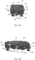
- FIGS. 10A-10C show the side actuators 26 slidably engaged with the rear plate 36 in collapsed and expanded positions, respectively.
- the side actuators 26 slide onto the rear plate 36 by aligning keying features that control expansion.
- FIG. 10A the actuators 26 are engaged with the rear plate 36 and collapsed onto one another.
- a recessed surface 162 on top of the actuator 26 sized and dimensioned to receive the other actuator 26 permits the actuators 26 to nest together, thereby providing a small footprint for insertion. It will be appreciated that a corresponding recessed surface 162 may be provided on the bottom of the opposite actuator 26 to provide for a complimentary fit. As best seen in FIG.
- one horizontal ramp 102 is positioned deeper than another horizontal ramp 102 to further facilitate this nesting configuration of the adjacent side actuators 26.
- the horizontal male ramps 154 of the side actuators 26 slidably interface with the horizontal female ramps 102 of the rear plate 36, thereby permitting lateral or horizontal movement of the left and right side assemblies 12, 14.
- the side actuators 26 may have features that engage with the mating rear plate 36, such as limiters 176, that limit the amount of translation while expanding in width. When expanded laterally in width, the side actuators 26 slide outward and away from one another, thereby increasing the width of the implant 10.
- FIG. 10B shows the side actuators 26 fully expanded in width relative to the rear plate 32.
- Front ramps 24 and front plate 32 utilize a similar sliding interface as actuators side 26 and rear plate 36.
- FIGS. 11A-11B show the front ramps 24 slidably engaged with the front plate 32 in collapsed and expanded positions, respectively. Front ramps 24 slide onto the front plate 32 by aligning keying features that control expansion.
- FIG. 11A the front ramps 24 are engaged with the front plate 32 and collapsed onto one another.
- a recessed surface 172 on top of one front ramp 24 sized and dimensioned to receive the other front ramp 24 permits the front ramps 24 to nest together, thereby providing a small footprint for insertion. It will be appreciated that a corresponding recessed surface 172 may be provided on the bottom of the opposite front ramp 24 to provide for a complimentary fit.
- one horizontal ramp 70 may be positioned at a depth greater than the other horizontal ramp 70 to further facilitate this nesting configuration of the front ramps 24.
- the horizontal ramps 170 of the front ramps 24 slidably interface with the horizontal ramps 70 of the front plate 32.
- the front ramps 24 may also have features that engage with the mating front plate 32, such as limiters 176, that limit the amount of translation while expanding in width. In FIG. 11B , the front ramps 24 are fully expanded in width. When expanded in width, the front ramps 24 slide outward and away from one another, thereby increasing the overall width of the implant 10.
- FIGS. 12A-12B show rear and perspective views, respectively, of the assembled implant 10 when fully expanded in width.
- the user is able to access the central drive assembly 16 through bore 88 in the rear plate 36.
- the drive nut 40 and drive screw 30 may be independently rotated or turned to actuate the implant 10.
- the threaded sleeve 38 is drawn proximally and the left and right side portions 12, 14 expand in width.
- the rear plate 36 which defines recesses 104, aligns with corresponding recesses 174 on the side actuators 28 to allow for access to a central portion of the implant 10.
- a graft delivery device may be used to enter a central open area inside the implant 10 and deliver graft material therein.
- the left and ride side portions 12, 14 expand in height.
- FIGS. 13A-13B show the implant 10 with the left side assembly 12 (one set of endplates 20, 22, side actuator 26, and front ramp 24 and hidden for clarity).
- the implant 10 may be fully collapsed to be inserted into a disc space, for example, through a posterior approach.
- the implant 10 may be attached to a multi-component instrument, for example.
- a first width driving instrument may be used to engage the recess 80 in the drive nut 40 with compatible drive features. When the drive nut 40 is rotated, it pulls or translates the threaded sleeve 38, central actuator 34, and front plate 32 proximally. When doing so, the drive nut 40 forces the side actuators 26 and front ramps 24 to translate outward and expand in width.
- FIG. 13A full width expansion has been achieved.
- a second height driving instrument may be used to engage the recess 52 in the drive screw 30 with compatible drive features.
- the drive screw 30 pulls or translates the front plate 32 and front ramps 24 proximally.
- the front ramps 24 translate proximally toward the side actuators 26 and force the endplates 20, 22 to translate upward and downward from the axial plane.
- the implant 10 is fully expanded in width and in height.
- the amount of height expansion on the left and right side assemblies 12, 14 may be the same or different. In this manner, the implant 10 is expanded in width for an increased footprint to aid in overall stability and the implant 10 is adjusted in lordosis and height for a precise patient fit.
- the implant 10 may have a dual-sided or single-sided width expansion.
- the expandable fusion device or implant 10 may be configured such that only one side assembly 12, 14 expands in width and the other remains stationary. Both of the left and right side portions 12, 14 may expand in height.
- the front and rear plates 32, 36 may include only a single horizontal ramp on each of the top and bottom faces to engage with a single side actuator 26 and front ramp 24, respectively. The single side that does not expand laterally outward may incorporate the front ramp features into the front distal plate 32 and the actuator features into the rear proximal plate 36.
- the implant 10 may be assembled as follows.
- the two front ramps 24 are placed onto the front plate 32 by aligning the slides or ramps 70, 170.
- One side actuator 26 is placed onto rear plate 36 by aligning the slides or ramps 102, 154.
- the central actuator 34 is placed onto the side actuator 26.
- the other side actuator 26 is placed onto the rear plate 36 and central actuator 34 by aligning slides or ramps 132, 156.
- the left and right sides 12, 14 may each be assembled by placing the lower endplate 22 onto the side actuator 26 and placing the upper endplate 20 onto side actuator 26.
- the front ramp 24 is placed into both the lower and upper endplates 20, 22.
- the threaded sleeve 38 is inserted into through the rear plate 36 and into central actuator 34 and secured.
- a friction ring 84 may be placed onto the drive nut 40.
- the drive nut 40 is then threaded on threaded sleeve 38 and bottomed out.
- the retaining sleeve 74 is pressed into rear plate 36, thereby securing drive nut 40.
- a friction ring 56 may be placed onto drive screw 30.
- Drive screw 30 is inserted through front plate 32 and threaded into central actuator 34.
- Retaining ring 58 may be placed into front plate 32, thereby securing drive screw 30.
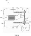
- the system 210 may include expandable implant 10, a plurality of bone fasteners 212, and a spinal rod 214 connecting the bone fasteners 212.
- the expandable fusion device 10 may be surgically implanted into an intervertebral disc space 202 situated between upper and lower vertebrae 204, 206.
- a posterior aspect of the spine may be accessed, for example, through a minimally invasive surgical procedure.
- the implant 10 may be implanted using a transforaminal lumbar interbody fusion (TLIF) procedure where a facet joint may be removed to access the disc space 202.
- the intervertebral disc or a portion thereof may be removed.
- the TLIF procedure may include a unilateral facetectomy to allow for visualization and removal of the disc.
- the implant 10 may be positioned in between the vertebrae 204, 206 to fuse the spine segment.
- the disc level or levels may be further stabilized by inserting bone fasteners 212, such as pedicle screws, into the vertebrae 204, 206 above and below the implant 10, and connecting a spinal rod 214 to the fasteners 212.
- the bone fasteners 212 may include bone screws, anchors, clamps, or the like configured to engage bone.
- the bone fastener 212 is a bone screw, which extends from a proximal end to a distal tip 216.
- the proximal end may include an enlarged head receivable within a modular tulip element 218, such as a polyaxial bone screw.
- the tulip head 218 is configured to secure spinal rod 214.
- the pedicle screws 212 may be used with a spinal fusion to add extra support and strength to the fusion while it heals.
- the pedicle screws 212 may be placed above and below the vertebrae 204, 206 to be fused.
- a bilateral construct may be used with a pair of rods 214 secured laterally along each side of the spine.
Landscapes
- Health & Medical Sciences (AREA)
- Engineering & Computer Science (AREA)
- Biomedical Technology (AREA)
- Neurology (AREA)
- Orthopedic Medicine & Surgery (AREA)
- Cardiology (AREA)
- Oral & Maxillofacial Surgery (AREA)
- Transplantation (AREA)
- Heart & Thoracic Surgery (AREA)
- Vascular Medicine (AREA)
- Life Sciences & Earth Sciences (AREA)
- Animal Behavior & Ethology (AREA)
- General Health & Medical Sciences (AREA)
- Public Health (AREA)
- Veterinary Medicine (AREA)
- Prostheses (AREA)
Abstract
Description
- The present disclosure generally relates to devices and methods for promoting an intervertebral fusion, and more particularly relates to expandable fusion devices capable of being inserted between adjacent vertebrae to facilitate the fusion process and related systems and methods.
- A common procedure for handling pain associated with intervertebral discs that have become degenerated due to various factors, such as trauma or aging, is the use of intervertebral fusion devices for fusing one or more adjacent vertebral bodies. Generally, to fuse the adjacent vertebral bodies, the intervertebral disc is first partially or fully removed. An intervertebral fusion device is then inserted between neighboring vertebrae to maintain normal disc spacing and restore spinal stability, thereby facilitating an intervertebral fusion.
- There are a number of fusion devices and methodologies for accomplishing the intervertebral fusion. These may include solid bone implants, fusion devices which include a cage or other implant mechanism, which may be packed with bone and/or bone growth inducing substances, and expandable implants. For example, posterior implants may be implanted to provide disc height restoration. The implants may be installed between adjacent vertebral bodies in order to fuse the vertebral bodies together, thereby alleviating the associated pain.
- There are drawbacks, however, with existing posterior implants including subsidence and sagittal balance issues. As such, there exists a need for fusion devices capable of being installed inside an intervertebral disc space at a minimum height and width with an expandable footprint to address the subsidence issue and an adjustable lordosis to address the sagittal balance issue.
- To meet this and other needs, devices, systems, and methods for performing intervertebral fusion and spine stabilization are provided. In particular, expandable intervertebral implants, for example, for posterior spinal surgery may be used to treat a variety of patient indications. The expandable implants are configured to increase the overall footprint size after being inserted into the disc space while also adjusting the lordosis and overall height. The in-situ expandable footprint or surface area is configured to address the subsidence issue and in-situ adjustable lordosis is configured to address the sagittal balance issue. The intervertebral implant may be combined with a posterior stabilization system, for example, including pedicle screws and spinal rod(s) to further stabilize the spine.
- According to one embodiment, an expandable intervertebral implant includes a central drive assembly and left and right side assemblies. The central drive assembly includes a central drive screw positioned through a front plate, the central drive screw threadedly engaged to a central actuator, the central actuator coupled to a threaded sleeve, and the threaded sleeve positioned through a rear plate and threadedly engaged with a drive nut. The left and right side assemblies each include upper and lower endplates, a side actuator, and a front ramp. The side actuator and front ramp are slidably engaged with the upper and lower endplates. Rotation of the drive nut expands the implant in width and rotation of the drive screw expands the implant in height.
- The expandable intervertebral implant may include one or more of the following features. The drive nut may pull the threaded sleeve and central actuator toward the rear plate and push the left and right side portions outwards in width. The drive screw may pull the front ramp toward the central actuator which then expands the upper and lower endplates in height. The central actuator may include a tubular body with an inner bore and a pair of opposite wings configured to mate with the side actuators. The rear plate may include a pair of female horizontal ramps defined into top and bottom surfaces of the rear plate, and the side actuator may include a pair of horizontal male ramps configured to interface with the female horizontal ramps of the rear plate. The front plate may include a pair of female horizontal ramps defined into top and bottom surfaces of the front plate, and the front ramp may include a pair of male horizontal ramps configured to interface with the female horizontal ramps of the front plate.
- According to one embodiment, an expandable intervertebral implant includes a front plate having a central through bore, a central drive screw having an enlarged head and a threaded shaft positioned through the bore in the front plate, a central actuator having a tubular body with a through bore and a pair of opposed wings, the threaded shaft of the central drive screw threadedly engaged within one end of the bore of the central actuator, a rear plate having a central through bore, a threaded sleeve positioned through the bore in the rear plate and threadedly engaged with an opposite end of the bore of the central actuator, a drive nut threadedly engaged with the threaded sleeve, and left and right side assemblies each including upper and lower endplates, a side actuator, and a front ramp. The side actuator and front ramp are slidably engaged with the upper and lower endplates, the side actuator is slidably engaged with the rear plate and central actuator, and the front ramp is slidably engaged with the front plate.
- The expandable intervertebral implant may include one or more of the following features. The left and right side assemblies may have a laterally collapsed configuration having a first width and a laterally expanded configuration having a second width, and the left and right side assemblies may have a vertically collapsed configuration having a first height and a vertically expanded configuration having a second height. The pair of opposed wings may each define a female ramp configured to receive a corresponding male ramp from the side actuator. The pair of opposed wings may be angled distally toward the front plate. The rear plate may include a cylindrical ring projecting proximally. The cylindrical ring may define an outer threaded surface. The threaded sleeve may include a first proximal exterior threaded section configured to interface with inner threads in a bore of the drive nut, and a second distal exterior threaded section configured to interface with inner threads in the bore of central actuator. The central drive screw may be retained in the front plate with a retaining ring. The drive nut may be retained in the rear plate with a retaining sleeve.
- According to another embodiment, an expandable intervertebral implant includes a central drive assembly and a side assembly. The central drive assembly includes a front plate, a central drive screw, a central actuator, a threaded sleeve, a rear plate, and a drive nut aligned along a central longitudinal axis. The central drive screw is retained in the front plate. The central actuator is threadedly engaged with the central drive screw and the threaded sleeve. The threaded sleeve is retained in the rear plate and threadedly engaged with the drive nut. The side assembly includes upper and lower endplates, a side actuator, and a front ramp. The side actuator and front ramp are slidably engaged with the upper and lower endplates. The side actuator is slidably engaged with the rear plate and central actuator, and the front ramp is slidably engaged with the front plate. When actuated, the drive nut controls width expansion of the implant and the drive screw controls height expansion of the implant.
- The expandable intervertebral implant may include one or more of the following features. The central drive screw may extend from a proximal end to a distal end where the distal end includes an enlarged head portion and the proximal end defines an instrument recess. The drive nut may define a central through bore and a proximal face of the drive nut may define an instrument recess different from the instrument recess of the central drive screw. The central drive screw may be located at a distal end of the implant and the drive nut may be located at a proximal end of the implant. When actuated, the drive nut may pull the threaded sleeve and central actuator proximally, thereby causing an expansion in width. When actuated, the central drive screw may pull the front plate toward the central actuator and pull the front ramp toward the side actuator, thereby causing an expansion in height.
- According to another embodiment, a method of assembling an expandable intervertebral implant may include one or more of the following steps in any suitable order: (1) placing two front ramps onto a front plate by aligning mating ramps or slides; (2) placing one side actuator onto a rear plate by aligning mating ramps or slides; (3) placing a central actuator onto the side actuator and placing a second side actuator onto the rear plate and the central actuator by aligning the ramps or slides; (4) assembling each of the left and right side assemblies by placing a lower endplate onto the side actuator and placing an upper endplate onto the side actuator; (5) placing the front ramp into both the lower and upper endplates; (6) inserting a threaded sleeve through the rear plate and into the central actuator; (7) placing a friction ring onto the drive nut; (8) threading the drive nut onto the threaded sleeve; (9) pressing a retaining sleeve into the rear plate to secure the drive nut; (10) placing a friction ring onto a central drive screw; (11) inserting the central drive screw through the front plate and threading into the central actuator; and (12) placing a retaining ring into the front plate to secure the central drive screw.
- According to another embodiment, a spinal fixation system includes an expandable intervertebral implant, a bone fastener, and a spinal rod attachable to the bone fastener. The expandable intervertebral implant comprising a central drive assembly and left and right side assemblies, the central drive assembly including a front plate, a central drive screw, a central actuator, a threaded sleeve, a rear plate, and a drive nut, and the left and right side assemblies each including upper and lower endplates, a side actuator, and a front ramp, wherein rotation of the drive nut is configured to expand the implant in width and rotation of the drive screw is configured to expand the implant in height.
- The spinal fixation system may include one or more of the following features. The expandable intervertebral implant may be configured to be installed through a transforaminal lumbar interbody fusion procedure. The bone fastener may include a threaded shaft and a tulip head. The bone fastener may be a polyaxial bone screw. The bone fastener may be a pedicle screw. The plurality of bone fasteners may be configured to be installed in vertebrae adjacent to the expandable intervertebral implant. The system may include a set of screws and rods configured to stabilize the spine.
- According to another embodiment, a spinal fixation system includes an expandable intervertebral implant comprising a central drive assembly and left and right side assemblies, and a posterior stabilization system. The central drive assembly includes a front plate having a central through bore, a central drive screw having an enlarged head and a threaded shaft positioned through the bore in the front plate, a central actuator having a tubular body with a through bore and a pair of opposed wings, the threaded shaft of the central drive screw threadedly engaged within one end of the bore of the central actuator, a rear plate having a central through bore, a threaded sleeve positioned through the bore in the rear plate and threadedly engaged with an opposite end of the bore of the central actuator, and a drive nut threadedly engaged with the threaded sleeve. The left and right side assemblies each include upper and lower endplates, a side actuator, and a front ramp,
- The spinal fixation system may include one or more of the following features. The posterior stabilization system may include a plurality of bone fasteners including a threaded shaft and a tulip head. The plurality of bone fasteners may be configured to be inserted into pedicles of adjacent vertebrae. The posterior stabilization system may include a spinal rod affixed to the tulip heads of the bone fasteners to stabilize a portion of the spine. Actuation of the drive nut may be configured to expand the intervertebral implant in width. Actuation of the central drive screw may be configured to expand the intervertebral implant in height in-situ.
- According to yet another embodiment, a method of spinal fixation may include one or more of the following steps in any suitable order: (1) inserting an expandable intervertebral implant into a disc space between adjacent vertebrae, the expandable implant comprising a central drive assembly and left and right side assemblies, the central drive assembly includes a front plate, a central drive screw, a central actuator, a threaded sleeve, a rear plate, and a drive nut, and the left and right side assemblies each include upper and lower endplates, a side actuator, and a front ramp; (2) expanding the implant in width and/or height; (3) affixing bone screws to pedicles of adjacent vertebrae; and (4) connecting a spinal rod between the bone screws. The method may further include expanding the implant in width by rotating the drive nut and expanding the implant in height by rotating the central drive screw. The implant may be expanded in width to increase an overall footprint size, thereby minimizing a potential for implant subsidence. The implant may be expanded in height in-situ to adjust lordosis. Before inserting the expandable intervertebral implant into the disc space, accessing a posterior aspect of a spine, and performing a facetectomy. A unilateral facetectomy may be performed to allow for visualization and removal of a disc. A first set of bone screws may be affixed to pedicles of the vertebrae, and a first spinal rod is connected therebetween, a second set of bone screw may be affixed to opposite pedicle of the vertebrae, and a second spinal rod is connected therebetween.
- According to yet another embodiment, a kit may include a plurality of implants of different sizes and configurations. The kit may further include one or more devices suitable for installing and/or removing the implants and systems described herein, such as insertion devices or drivers; one or more removal devices; and other tools and devices, which may be suitable for surgery.
- The present embodiments will become more fully understood from the detailed description and the accompanying drawings, wherein:
-
FIGS. 1A-1C illustrate perspective views of an expandable implant in a collapsed position, expanded in width, and expanded in width and height, respectively, according to one embodiment; -
FIG. 2 shows an exploded view of the expandable implant ofFIGS. 1A-1C ; -
FIG. 3 shows an exploded view of a portion of the central drive assembly including a central drive screw insertable into a front plate and configured to be retained by a retaining ring according to one embodiment; -
FIG. 4 shows an exploded view of another portion of the central drive assembly including a central drive nut, rear plate, threaded sleeve, and retaining sleeve for securing the drive nut in the rear plate according to one embodiment; -
FIG. 5 shows the central drive assembly including the rear plate attached to the drive sleeve, the drive sleeve attached to the central actuator, the central actuator attached to the central drive screw, and the central drive screw attached to the front plate according to one embodiment; -
FIG. 6 shows a side assembly including the top endplate assembled onto the side actuator and the front ramp and a lower endplate configured to be placed onto the side actuator and front ramp during assembly; -
FIG. 7 shows a cross-sectional view of the ramps of the upper and lower endplates engaged with the side actuator and front ramp according to one embodiment; -
FIG. 8 shows the side actuator of the side assemblies according to one embodiment; -
FIG. 9 shows the front ramp of the side assemblies according to one embodiment; -
FIGS. 10A-10C illustrate the side actuators slidably engaged with the rear plate in a collapsed position and expanded in width, respectively, and a close-up view of the interaction between the side actuator and the rear plate according to one embodiment; -
FIGS. 11A-11B illustrate the front ramps slidably engaged with the front plate in a collapsed position and expanded in width, respectively, according to one embodiment; -
FIGS. 12A-12B show rear and perspective views, respectively, of the implant expanded in width according to one embodiment; -
FIGS. 13A-13B show the implant fully expanded in width and fully expanded in width and height, respectively, according to one embodiment (one side assembly including one set of endplates, side actuator, and front ramp are omitted for clarity); and -
FIG. 14 illustrates a spinal construct including the expandable implant in combination with pedicle screws and attached spinal rod for stabilizing the posterior spine according to one embodiment. - Embodiments of the disclosure are generally directed to devices, systems, and methods for intervertebral fusion and spine stabilization. Specifically, expandable implants are configured to increase the overall footprint size after being inserted into the disc space while also adjusting the lordosis and overall height. The expandable implants may include one or more side assemblies configured to expand in width and in height. In doing so, the expansion addresses sagittal balance correction and subsidence issues. The intervertebral implant may be combined with a posterior stabilization system, for example, including pedicle screws and spinal rod(s) to further stabilize the spine.
- A spinal fusion is typically employed to eliminate pain caused by motion of degenerated disc material. Upon successful fusion, a fusion device becomes permanently fixed within the intervertebral disc space. The expandable fusion device may be positioned between adjacent vertebral bodies in a collapsed position. The expandable fusion device is configured to expand in width and subsequently in height. The fusion device engages the endplates of the adjacent vertebral bodies and, in the installed position, maintains desired intervertebral disc spacing and restores spinal stability, thereby facilitating the intervertebral fusion.
- Minimally invasive surgery (MIS) may be used to preserve muscular anatomy by only causing disruption where necessary. The benefit of the MIS surgical approach is that it can reduce post-operative pain and improve recovery time for patients. In one embodiment, the expandable fusion device can be configured to be placed down an endoscopic tube and into the surgical target site. By way of example, the surgical site may be an intervertebral disc space situated between two adjacent vertebrae. Although particularly suited for use in a transforaminal lumbar interbody fusion (TLIF), it will be readily appreciated by those skilled in the art that the implant may be employed in any number of suitable orthopedic approaches and procedures, including but not limited to, anterior, posterior, lateral, anterolateral, or posterolateral approaches to the lumbar spine, cervical spine, or thoracic spine, as well as any non-spine application, such as treatment of bone fractures and the like.
- Components of all of the devices disclosed herein may be manufactured of any suitable materials including metals (e.g., titanium), metal alloys (e.g., stainless steel, cobalt-chromium, and titanium alloys), ceramics, plastics, plastic composites, or polymeric materials (e.g., polyether ether ketone (PEEK), polyphenylene sulfone (PPSU), polysulfone (PSU), polycarbonate (PC), polyetherimide (PEI), polypropylene (PP), polyacetals, or mixtures or co-polymers thereof), and/or combinations thereof. In some embodiments, the devices may include radiolucent and/or radiopaque materials. The components can also be machined and/or manufactured using any suitable techniques (e.g., 3D printing).
- Turning now to the drawing, where like reference numerals refer to like elements,
FIGS. 1A-1C illustrate an expandable fusion device orimplant 10 according to one embodiment. Theexpandable fusion device 10 may include left and rightside portion assemblies device 10 and expand in height to correct disc height restoration, lordosis, and/or sagittal balance. Theimplant 10 may be suitable for a transforaminal lumbar interbody fusion (TLIF) through a posterior approach or other suitable surgical procedure. - The
expandable fusion device 10 extends along a central longitudinal axis A between front and rear ends of thedevice 10.FIG. 1A shows theexpandable fusion device 10 in a fully collapsed configuration with the left andright side portions FIG. 1B shows theexpandable fusion device 10 in an expanded configuration with the left andright side portions FIG. 1C shows the expandable fusion device in a fully expanded configuration with the left andright side portions right side portions expandable fusion device 10 placed into the disc space first, followed by the rear of theexpandable fusion device 10. These and other directional terms may be used herein for descriptive purposes and do not limit the orientation(s) in which the devices may be used. - With emphasis on the exploded view in
FIG. 2 , theimplant 10 includes a first half orleft side portion 12, a second half orright side portion 14, and acentral drive assembly 16. The left and rightside portion assemblies lower endplates front ramp 24, and aside actuator 26. Thecentral drive assembly 16 includes acentral drive screw 30, afront plate 32, acentral actuator 34, arear plate 36, a central threadedsleeve 38, and acentral drive nut 40 aligned along the central longitudinal axis A. - The
front plate 32 is operatively coupled to the front part of the first half orleft side portion 12 and the second half orright side portion 14 and to thecentral drive screw 30. - The
rear plate 36 is operatively coupled to the rear part of the first half orleft side portion 12 and the second half orright side portion 14 and to thecentral drive nut 40. - The left and
right side portions central drive nut 40. The upper andlower endplates central drive screw 30. - In particular, the left and
right side portions central drive nut 40 which is attached to the central threadedsleeve 38 andcentral actuator 34. Thedrive nut 40 pulls the threadedsleeve 38 andcentral actuator 34 toward therear plate 36 and pushes the left andright side portions right side portions front plate 32 is controllable by thecentral drive screw 30. Thecentral drive screw 30 pulls thefront plate 20 toward thecentral actuator 34 while also pulling thefront ramps 24 toward theside actuators 26. Eachside assembly lower endplates front ramp 24, andside actuator 26. Thefront ramp 24 is actuated while thedrive screw 30 is turned. This pulls thefront ramp 24 toward theside actuator 26 which then expands the top andbottom endplates mating ramps front ramps 24 andside actuators 26. - As best seen in
FIG. 3 , thecentral drive screw 30 extends from aproximal end 44 to adistal end 46. Thedistal end 46 may include anenlarged head portion 48 configured to be received in abore 62 defined through thefront plate 32. Theenlarged head 48 may include a wide cylindrical head with a smooth outer surface at the distal end of thecentral drive screw 30. Theproximal end 44 of thedrive screw 30 may define aninstrument recess 50 configured to receive an instrument, such as a driver, to rotate or actuate thedrive screw 30. Theinstrument recess 50 may include a tri-lobe, hex, star, or other suitable recess configured to engage with a driver instrument to apply torque to thedrive screw 30. Thedrive screw 30 may include a shaft with an exterior threadedportion 52 extending along its length. Theexterior threads 52 may extend from theproximal end 44 to a location near the bottom of theenlarged head 48. Thedrive screw 30 is receivable through thebore 62 in thefront plate 32 such that theenlarged head portion 48 of thedrive screw 30 is receivable in thefront plate 32. Anoptional friction ring 56, such as a polyether ether ketone (PEEK) ring, may be assembled onto thedrive screw 30, for example, below theenlarged head 48, to increase friction or drag on thedrive screw 30 during rotation. - The
central drive screw 30 is inserted into thefront plate 32 and may be retained within thefront plate 32 using a retainingring 58. Thedrive screw 30 controls height expansion of theimplant 10 when actuated. The retainingring 58 may include a split ring with a plurality of inner and/orouter teeth 60 or various reliefs to allow the retainingring 58 to compress and enter thebore 62 of thefront plate 32 and engage an internal groove. The retainingring 60 may include two slots, for example, to be engaged with an instrument to aid insertion and removal of the retainingring 58. When the retainingring 58 is positioned around thedrive screw 30 and within thebore 62 in thefront plate 32, theteeth 58 are configured to engage with thecentral drive screw 30, thereby locking thescrew 30 in position in theplate 32. - The
front plate 32 defines acentral bore 62 therethrough configured to receivedrive screw 30. The axis ofbore 62 is aligned along central longitudinal axis A. Thefront plate 32 includes an upper face ortop surface 64 and an opposite lower face orbottom surface 66 connected by side surfaces 68. The top andbottom surfaces corresponding ramps 170 on thefront ramps 24 of the left andright side portions male counterparts 170 of thefront ramps 24. It will be appreciated, however, that the female/male configurations may be reversed or may include other suitable ramp interactions, sliding features, or mating components to provide lateral expansion of the left and rideside portions - In one embodiment, the
front plate 32 may include a first pair ofhorizontal ramps 70 defined into the top 64 of thefront plate 32 and a second pair ofhorizontal ramps 70 defined into the bottom 66 of thefront plate 32. Each of theramps 70 may be aligned along distinct horizontal planes. In this manner, eachramp 70 has a constant depth along its length such that one of the female horizontal ramps has a depth greater than the other female horizontal ramp. For example, afirst ramp 70 defined along the top 64 of thefront plate 32 may be positioned along one given horizontal plane lower or higher relative to theother ramp 70 defined along the top 64 of thefront plate 32. Thehorizontal ramps 70 may be angled, diagonal, or slanted such that one end of eachramp 70 begins at aside 68 of thefront plate 32 and extend centrally in a direction toward thecentral actuator 34 with theramps 70 leading toward one another. Although described as horizontal ramps to provide for horizontal or lateral expansion of the left andright side assemblies horizontal ramps 70 may be sloped, slanted, or otherwise configured off axis to provide for a different trajectory or type of expansion. - As best seen in
FIG. 4 , drivenut 40 is inserted into therear plate 36 and may be retained using retainingsleeve 74. Thedrive nut 40 controls width expansion of theimplant 10 when actuated. Thedrive nut 40 may have a generally cylindrical body that extends from aproximal end 76 to adistal end 78. Theproximal face 76 may define one or more indentions or notches to form aninstrument recess 80 configured to interface with an instrument, such as a driver, to rotate or actuate thedrive nut 40. Theinstrument recess 80 may define a slotted, splined, tri-lobe, hex, star, other suitable recess, or a portion thereof configured to engage with a driver instrument to apply torque to thedrive nut 40. Theinstrument recess 80 of thedrive nut 40 may be of a different type than theinstrument recess 50 of thedrive screw 30 so the user can easily discern which component is intended to be actuated. In this manner, theinstrument recess 80 is configured to engage with a driver instrument to apply torque to thedrive nut 40, thereby driving width expansion of the left andright side assemblies - The
drive nut 40 defines a central throughbore 82 such that another instrument is able to access thedistal drive screw 30. The axis of throughbore 82 may aligned along central longitudinal axis A. Thedrive nut 40 is receivable within thebore 88 in therear plate 36 such that the body of thedrive nut 40 is receivable in therear plate 36. Anoptional friction ring 84, such as a polyether ether ketone (PEEK) ring, may be assembled onto thedrive nut 40, for example, neardistal end 78, to increase friction or drag on thedrive nut 40 during rotation. The retainingsleeve 74 is pressed into therear plate 36, thereby securing thedrive nut 40 in therear plate 36. The retainingsleeve 74 may include a ring or band sized and dimensioned to fit around thedrive nut 40 and within theprojection 96 of therear plate 36. - The
rear plate 36 defines acentral bore 88 therethrough configured to receivedrive nut 40 and threadedsleeve 38. The axis ofbore 88 is aligned along central longitudinal axis A. Therear plate 36 includes an upper face ortop surface 90 and an opposite lower face orbottom surface 92 connected by side surfaces 94. Aprojection 96 may extend proximally defining a substantially cylindrical ring with an outer threadedportion 98, for example, configured to threadedly engage with an implant insertion instrument. A threaded connection to therear plate 36 provides for a rigid connection to the insertion instrument. The top andbottom surfaces ramps 102 configured to interface withcorresponding ramps 154 on the side actuators 26 of the left andright side portions - The
rear plate 36 includes one or more slides orramps 102 configured to interface withcorresponding ramps 154 on theactuators 26 of the left andright side portions rear plate 36, therear plate 36 may include a pair oframps 102 defined into each of the top andbottom surfaces rear plate 36. Similar toramps 70,ramps 102 may be horizontal ramps aligned along one or more horizontal planes. For example, one of the pair oframps 102 may be positioned along one given horizontal plane lower or higher relative to theother ramp 102 along another given horizontal plane. In other words, eachramp 102 has a constant depth along its length such that oneramp 102 has a depth greater than theother ramp 102. Thehorizontal ramps 102 may be angled, diagonal, or slanted such that one end of theramp 102 starts at aside 94 of therear plate 36 and extends toward the center of therear plate 36 with theramps 102 leading toward one another. Thehorizontal ramps 102 may define female channels or grooves configured to receive the matingmale counterparts 154 of theactuators 26. It will be appreciated, however, that the female/male configurations may be reversed or may include other suitable ramp interactions, sliding features, or mating components to provide lateral expansion of the left andright side portions - The
rear plate 36 may include one or more instrument recesses orslots implant 10. For example, the side faces 94 of therear plate 36 may each include side recesses orinstrument slots 104 configured to receive a graft delivery device. For example,opposite sides 94 of therear plate 36 may include two opposedsemi-circular recesses 104 configured to allow the graft delivery device to enter the central portion of theimplant 10 once fully expanded in width and/or height. Bone graft or similar bone growth inducing material can be introduced within and/or around thefusion device 10 to further promote and facilitate the intervertebral fusion. In addition, one ormore recesses 106 may be positioned about the proximal face of therear plate 36. Thesecircular recesses 106 may be aligned at the four corners of theplate 36. The quadruple recesses 106 may help to align an instrument, such as insertion instrument. - The
drive nut 40 is threaded onto threadedsleeve 38. The threadedsleeve 38 is positioned throughbore 88 ofrear plate 36 and threadedly engaged to drivenut 40. The threadedsleeve 38 is a cylindrical sleeve or shaft sleeve defining a central throughbore 114 betweenproximal end 110 anddistal end 112 of thesleeve 38. The axis of thecentral bore 114 aligns with the central longitudinal axis A. An outer surface of thesleeve 38 includes exterior threadedsections section 116 is configured to interface with inner threads inbore 82 ofdrive nut 40. A second distal exterior threadedsection 118 is configured to interface with inner threads inbore 124 ofcentral actuator 34. The threadedsections 116 may include helically wound thread forms having any suitable lead, pitch, handedness, angle, diameters, etc. Theseparate thread sections thread sections smooth section 120. The proximal threadedsection 116 may be longer than the distal threadedsection 118 such that thenon-threaded section 120 is located closer to thedistal end 112 of thesleeve 38. For example, the length of the proximal threadedsection 116 may be double, triple, quadruple, or greater than the length of the distal threadedsection 118. - Turning now to
FIG. 5 , the fully assembledcentral drive assembly 16 is shown. The threadedsleeve 38 is attached tocentral actuator 34. Thecentral actuator 34 includes a tubular body with aninner bore 124 extending from aproximal end 126 to adistal end 128. Theinner bore 124 of thecentral actuator 34 is internally threaded to allow for threaded engagement with the distal threadedsection 118 of the threadedsleeve 38 and the threadedshaft 52 of thedrive screw 30. Thecentral actuator 34 includes a pair ofopposite wings 130 extending from an outer surface of the tubular body. Eachwing 130 may terminate at a distal free end. Thewings 130 may be angled such that the distal free ends of thewings 130 point toward thefront plate 32. Eachwing 130 may define one or more slides orramps 132 configured to mate with corresponding surfaces on theside actuators 26. Theramps 132 may be angled, diagonal, chamfered, or slanted such that one end of theramp 132 starts at the body of thecentral actuator 34 and extends to the free end of therespective wing 130. Theramps 132 may define female channels or grooves configured to receive the matingmale counterparts 156 of theside actuators 26. Thefemale ramps 132 may extend openly along a proximal face of eachwing 130. It will be appreciated that the female/male configurations and locations may be reversed or changed to include other suitable ramp interactions, sliding features, or mating components to help provide lateral expansion of the left andright side portions - When the
central drive assembly 16 is assembled, theproximal end 110 of the threadedsleeve 38 is positioned through thebore 88 in therear plate 36. Thedrive nut 40 is threaded onto the proximal threadedsection 116 of the threadedsleeve 38. The distal threadedsection 118 of the threadedsleeve 38 is threaded into thecentral actuator 34. The actuation of thedrive nut 40 is configured to push and pull the threadedsleeve 38 andcentral actuator 34 relative to therear plate 36 and expand theimplant 10 in width once fully assembled. Thedrive screw 30 is positioned through thebore 62 in thefront plate 32. The threadedshaft 52 of thedrive screw 30 is threaded into thedistal end 128 of thecentral actuator 34, which is attached to the threadedsleeve 38. The actuation of thedrive screw 30 is configured to push and pull thefront plate 32 andfront ramps 24 relative to thecentral actuator 34 andside actuators 26 and expand theimplant 10 in height once fully assembled. - Turning now to
FIGS. 6 and 7 , the left andright side assemblies lower endplates side actuator 26 andfront ramp 24. The left and rightside portion assemblies lower endplates expandable fusion device 10. The upper andlower endplates assembly 12 andupper endplate 20, the discussion herein applies equally toassembly 14 andlower endplate 22. Theupper endplate 20 includes an upper or outer facingsurface 136 configured to interface with the vertebral endplate(s) of the adjacent vertebral bodies when implanted in the disc space. Theouter surface 136 may include a plurality of teeth, ridges, roughened surfaces, keels, gripping or purchasing projections, or other friction increasing elements configured to retain thedevice 10 in the disc space. For example, theendplates - The
upper endplate 20 includes a lower orinner facing surface 138 and one ormore side walls 140 defining one or more slides orramps 142 configured to interface withcorresponding ramps actuator 26 andfront ramp 24, respectively. For example, theupper endplate 20 may define a pair ofsidewalls 140 forming a gap orchannel 144 therebetween. Thechannel 144 may be generally U-shaped, J-shaped, C-shaped, or another suitable configuration. At least three pairs oframps 142 may be defined within thechannel 144 of theendplate 20. Theramps 142 may be vertical ramps aligned along one or more vertical planes. In one embodiment, all three pairs ofvertical ramps 142 may be aligned along the same plane. Although vertically-oriented, thevertical ramps 142 may be angled, diagonal, or sloped to increase the vertical height of theendplates - In one embodiment, two pairs of
vertical ramps 142 interfaced with theside actuator 26 may be angled in one direction and a third pair ofvertical ramps 142 interfaced with thefront ramp 24 may be angled in an opposite direction. For example, the distal-mostvertical ramps 142, nearfront ramp 24, may be sloped such that they points toward thefront ramp 24 as they extend along theside walls 140 from theinner surface 138 toward theouter surface 136. Similarly, the proximal-mostvertical ramps 142, near theside actuator 26, and centrally locatedvertical ramps 142, may be sloped such that they point toward theside actuator 26 as they extend along theside walls 140 from theinner surface 138 toward theouter surface 136. The proximal-mostvertical ramps 142 and centralvertical ramps 142 may be aligned in parallel with the same degree of slope or may have different degrees of slope. - The
vertical ramps 142 may define female channels or grooves configured to receive the matingmale counterparts side actuator 26 andfront ramp 24, respectively. It will be appreciated that the female/male configurations may be reversed or may include other suitable ramp interactions, sliding features, or mating components to provide vertical expansion of the left and rideside portions right side assemblies vertical ramps 142 may be sloped, slanted, or otherwise configured off axis to provide for a different trajectory or type of expansion. - One or
more openings 146 may extend vertically through the body of theendplate FIG. 1A ,ramp portions 160 of theside actuators 26 may be received through theopenings 146. Similarly, when expanded in width, as shown inFIG. 1B , theramps 160 of theside actuators 26 are receivable through theopenings 146 in theendplates FIG. 1C , theopenings 146 may be open and free to receive bone-graft or other suitable bone forming material. One or more openings orslots 148 may extend horizontally through thesidewalls 140 of theendplate slots 148 may be provided between the distal-most and centralvertical ramps 142 and near theinner surface 138 of theendplate FIG. 1A ,slots 148 from the upper andlower endplates wings 130 of thecentral actuator 34 is positionable through theopenings 148. When expanded in width, as shown inFIG. 1B , theside assemblies openings 148 or a portion thereof are vacant. - Turning now to
FIG. 8 , the left and rightside portion assemblies second side actuators 26 positioned between the upper andlower endplates right side portions actuator 26 may include a body extending along a central axis A1 from aproximal end 150 to adistal end 152. Central axis A1 may be generally parallel with central longitudinal axis A. Theproximal end 150 may define one or more horizontal slides orramps 154 configured to engage with thehorizontal ramps 102 of therear plate 36. Theside actuator 26 may define a pair of top and bottomhorizontal ramps 154 pointing inwardly toward one another. Thehorizontal ramps 154 may have an angled, diagonal, or slanted surface in a manner complimentary to theramps 102 of therear plate 36. In particular, thehorizontal ramps 154 may define male projections configured to enter thefemale counterparts 102 of therear plate 36. Theramp 154 may define alimiter 176 to end movement of the mating slides or ramps 102, 154. For example, thelimiter 176 may include a widened ramp surface, a projection or protrusion, a bevel or dovetail, etc. configured to reduce or limit the relative movement between theramps - The
distal end 152 of theside actuator 26 may includeramp 156 configured to engage with thecorresponding ramp 132 on thewing 130 of thecentral actuator 34. Theside actuator 26 may define upper andlower grooves 158 to form a singlemale ramp 156 pointing distally. Themale ramp 156 may have an angled, diagonal, or slanted surface in a manner complimentary to thefemale ramp 132 onwing 130 of thecentral actuator 34. Thisslidable interface second side assemblies - The
actuator 26 includes a plurality oframps 160 configured to engage with theendplates actuator 26 may define a plurality ofvertical ramps 160 configured to engage with thevertical ramps 142 of theendplates actuator 26 may define a first set ofvertical ramps 160 slanted upwardly toward theproximal end 150 or downwardly toward thedistal end 152 and a second set ofvertical ramps 160 slanted upwardly toward thedistal end 152 or downwardly toward theproximal end 150 of theactuator 26. Each set oframps 160 may define a pair of male projections configured to enter thefemale counterparts 142 of theendplates vertical ramps 160 may have an angled, diagonal, or sloped surface in a manner complimentary to the correspondingramps 142 of theendplates - As shown in
FIG. 9 , the left andright side portions front ramp 24 configured to expand the distal or front ends of the upper andlower endplates front ramp 24 may include a body extending from aproximal end 164 to adistal end 166. Theproximal end 164 may define one or morevertical ramps 168 configured to engage with thevertical ramps 142 of theendplates front ramp 24 may define firstvertical ramps 168 sloped downwardly toward theproximal end 164 and a secondvertical ramp 168 sloped upwardly toward theproximal end 164 of thefront ramp 24. Each oframps 168 may define a pair of opposed male projections configured to enter thefemale counterparts 142 in thechannel 144 of theendplates male ramps 168 may have an angled, diagonal, or sloped surface in a manner complimentary to thefemale ramps 142 of theendplates - The
distal end 166 of thefront ramp 24 may define one or morehorizontal ramps 170 configured to engage with thehorizontal ramps 70 of thefront plate 32. Thefront ramp 32 may define a pair of top and bottomhorizontal ramps 170 separated by a gap and pointing inwardly toward one another. Thehorizontal ramps 170 may have an angled, diagonal, or slanted surface in a manner complimentary to theramps 70 of thefront plate 32. In particular, thehorizontal ramps 170 may define male projections configured to enter thefemale counterparts 70 of thefront plate 32. Similar toramps 154, theramps 170 may define alimiter 176 to end movement of the mating slides or ramps 70, 170. For example, thelimiter 176 may include a widened ramp surface, a projection or protrusion, a bevel or dovetail, etc. configured to reduce or limit the relative movement between theramps -
FIGS. 10A-10C show theside actuators 26 slidably engaged with therear plate 36 in collapsed and expanded positions, respectively. The side actuators 26 slide onto therear plate 36 by aligning keying features that control expansion. InFIG. 10A , theactuators 26 are engaged with therear plate 36 and collapsed onto one another. A recessedsurface 162 on top of the actuator 26 sized and dimensioned to receive theother actuator 26 permits theactuators 26 to nest together, thereby providing a small footprint for insertion. It will be appreciated that a corresponding recessedsurface 162 may be provided on the bottom of theopposite actuator 26 to provide for a complimentary fit. As best seen inFIG. 10C , onehorizontal ramp 102 is positioned deeper than anotherhorizontal ramp 102 to further facilitate this nesting configuration of theadjacent side actuators 26. The horizontal male ramps 154 of theside actuators 26 slidably interface with the horizontalfemale ramps 102 of therear plate 36, thereby permitting lateral or horizontal movement of the left andright side assemblies rear plate 36, such aslimiters 176, that limit the amount of translation while expanding in width. When expanded laterally in width, theside actuators 26 slide outward and away from one another, thereby increasing the width of theimplant 10.FIG. 10B shows theside actuators 26 fully expanded in width relative to therear plate 32. - Front ramps 24 and
front plate 32 utilize a similar sliding interface asactuators side 26 andrear plate 36.FIGS. 11A-11B show thefront ramps 24 slidably engaged with thefront plate 32 in collapsed and expanded positions, respectively. Front ramps 24 slide onto thefront plate 32 by aligning keying features that control expansion. InFIG. 11A , thefront ramps 24 are engaged with thefront plate 32 and collapsed onto one another. A recessedsurface 172 on top of onefront ramp 24 sized and dimensioned to receive the otherfront ramp 24 permits thefront ramps 24 to nest together, thereby providing a small footprint for insertion. It will be appreciated that a corresponding recessedsurface 172 may be provided on the bottom of theopposite front ramp 24 to provide for a complimentary fit. Similar torear plate 36, onehorizontal ramp 70 may be positioned at a depth greater than the otherhorizontal ramp 70 to further facilitate this nesting configuration of thefront ramps 24. Thehorizontal ramps 170 of thefront ramps 24 slidably interface with thehorizontal ramps 70 of thefront plate 32. The front ramps 24 may also have features that engage with themating front plate 32, such aslimiters 176, that limit the amount of translation while expanding in width. InFIG. 11B , thefront ramps 24 are fully expanded in width. When expanded in width, thefront ramps 24 slide outward and away from one another, thereby increasing the overall width of theimplant 10. -
FIGS. 12A-12B show rear and perspective views, respectively, of the assembledimplant 10 when fully expanded in width. The user is able to access thecentral drive assembly 16 throughbore 88 in therear plate 36. In particular, thedrive nut 40 and drivescrew 30 may be independently rotated or turned to actuate theimplant 10. When thedrive nut 40 is actuated, the threadedsleeve 38 is drawn proximally and the left andright side portions rear plate 36, which definesrecesses 104, aligns withcorresponding recesses 174 on the side actuators 28 to allow for access to a central portion of theimplant 10. In this manner, a graft delivery device may be used to enter a central open area inside theimplant 10 and deliver graft material therein. When thedrive screw 30 is actuated, the left and rideside portions -
FIGS. 13A-13B show theimplant 10 with the left side assembly 12 (one set ofendplates side actuator 26, andfront ramp 24 and hidden for clarity). Theimplant 10 may be fully collapsed to be inserted into a disc space, for example, through a posterior approach. Theimplant 10 may be attached to a multi-component instrument, for example. A first width driving instrument may be used to engage therecess 80 in thedrive nut 40 with compatible drive features. When thedrive nut 40 is rotated, it pulls or translates the threadedsleeve 38,central actuator 34, andfront plate 32 proximally. When doing so, thedrive nut 40 forces theside actuators 26 andfront ramps 24 to translate outward and expand in width. Once thecentral actuator 34 andrear plate 36 come in contact with each other thedrive nut 40 cannot be turned any further. As shown inFIG. 13A , full width expansion has been achieved. A second height driving instrument may be used to engage therecess 52 in thedrive screw 30 with compatible drive features. When thedrive screw 30 is rotated, thedrive screw 30 pulls or translates thefront plate 32 andfront ramps 24 proximally. When doing so, thefront ramps 24 translate proximally toward theside actuators 26 and force theendplates front plate 32 and thecentral actuator 34 come in contact with each other thedrive screw 30 cannot be turned any further. As shown inFIG. 13B , theimplant 10 is fully expanded in width and in height. The amount of height expansion on the left andright side assemblies implant 10 is expanded in width for an increased footprint to aid in overall stability and theimplant 10 is adjusted in lordosis and height for a precise patient fit. - The
implant 10 may have a dual-sided or single-sided width expansion. In one embodiment, the expandable fusion device orimplant 10 may be configured such that only oneside assembly right side portions rear plates single side actuator 26 andfront ramp 24, respectively. The single side that does not expand laterally outward may incorporate the front ramp features into the frontdistal plate 32 and the actuator features into the rearproximal plate 36. - The
implant 10 may be assembled as follows. The twofront ramps 24 are placed onto thefront plate 32 by aligning the slides or ramps 70, 170. Oneside actuator 26 is placed ontorear plate 36 by aligning the slides or ramps 102, 154. Thecentral actuator 34 is placed onto theside actuator 26. The other side actuator 26 is placed onto therear plate 36 andcentral actuator 34 by aligning slides or ramps 132, 156. The left andright sides lower endplate 22 onto theside actuator 26 and placing theupper endplate 20 ontoside actuator 26. Thefront ramp 24 is placed into both the lower andupper endplates sleeve 38 is inserted into through therear plate 36 and intocentral actuator 34 and secured. Afriction ring 84 may be placed onto thedrive nut 40. Thedrive nut 40 is then threaded on threadedsleeve 38 and bottomed out. The retainingsleeve 74 is pressed intorear plate 36, thereby securingdrive nut 40. Afriction ring 56 may be placed ontodrive screw 30. Drivescrew 30 is inserted throughfront plate 32 and threaded intocentral actuator 34. Retainingring 58 may be placed intofront plate 32, thereby securingdrive screw 30. - Turning now to
FIG. 14 , asystem 210 for intervertebral fusion is shown according to one embodiment. Thesystem 210 may includeexpandable implant 10, a plurality ofbone fasteners 212, and aspinal rod 214 connecting thebone fasteners 212. Theexpandable fusion device 10 may be surgically implanted into anintervertebral disc space 202 situated between upper andlower vertebrae implant 10 may be implanted using a transforaminal lumbar interbody fusion (TLIF) procedure where a facet joint may be removed to access thedisc space 202. The intervertebral disc or a portion thereof may be removed. The TLIF procedure may include a unilateral facetectomy to allow for visualization and removal of the disc. Theimplant 10 may be positioned in between thevertebrae - The disc level or levels may be further stabilized by inserting
bone fasteners 212, such as pedicle screws, into thevertebrae implant 10, and connecting aspinal rod 214 to thefasteners 212. Thebone fasteners 212 may include bone screws, anchors, clamps, or the like configured to engage bone. In the embodiment shown, thebone fastener 212 is a bone screw, which extends from a proximal end to adistal tip 216. The proximal end may include an enlarged head receivable within amodular tulip element 218, such as a polyaxial bone screw. Thetulip head 218 is configured to securespinal rod 214. Examples of bone fasteners and other implants and rod constructs are described in more detail, for example, inU.S. Patent No. 10,368,917 vertebrae single rod 214 is shown, a bilateral construct may be used with a pair ofrods 214 secured laterally along each side of the spine. - Although the invention has been described in detail and with reference to specific embodiments, it will be apparent to one skilled in the art that various changes and modifications can be made without departing from the scope of the invention. Thus, it is intended that the invention covers the modifications and variations of this invention provided they come within the scope of the appended claims and their equivalents. It is expressly intended, for example, that all components of the various devices disclosed above may be combined or modified in any suitable configuration.
- The invention could be inter alia defined by the following examples:
- 1. An expandable intervertebral implant comprising: a central drive assembly including a central drive screw positioned through a front plate, a central actuator threadedly engaged to the central drive screw, a threaded sleeve coupled to the central actuator, the threaded sleeve positioned through a rear plate and threadedly engaged with a drive nut; and left and right side assemblies each including upper and lower endplates, a side actuator, and a front ramp, wherein the side actuator and front ramp are slidably engaged with the upper and lower endplates, wherein rotation of the drive nut expands the implant in width and rotation of the drive screw expands the implant in height.
- 2. The expandable intervertebral implant of Example 1, wherein the drive nut pulls the threaded sleeve and central actuator toward the rear plate and pushes the left and right side portions outwards in width.
- 3. The expandable intervertebral implant of Example 1, wherein the central drive screw pulls the front ramp toward the central actuator which then expands the upper and lower endplates in height.
- 4. The expandable intervertebral implant of Example 1, wherein the central actuator includes a tubular body with an inner bore and a pair of opposite wings configured to mate with the side actuators.
- 5. The expandable intervertebral implant of Example 1, wherein the rear plate includes a pair of female horizontal ramps defined into top and bottom surfaces of the rear plate, and the side actuator includes a pair of horizontal male ramps configured to interface with the female horizontal ramps of the rear plate.
- 6. The expandable intervertebral implant of Example 1, wherein the front plate includes a pair of female horizontal ramps defined into top and bottom surfaces of the front plate, and the front ramp includes a pair of male horizontal ramps configured to interface with the female horizontal ramps of the front plate.
- 7. An expandable intervertebral implant comprising: a front plate having a central through bore; a central drive screw having an enlarged head and a threaded shaft positioned through the bore in the front plate; a central actuator having a tubular body with a through bore and a pair of opposed wings, the threaded shaft of the central drive screw threadedly engaged within one end of the bore of the central actuator; a rear plate having a central through bore; a threaded sleeve positioned through the bore in the rear plate and threadedly engaged with an opposite end of the bore of the central actuator; a drive nut threadedly engaged with the threaded sleeve; and left and right side assemblies each including upper and lower endplates, a side actuator, and a front ramp, wherein the side actuator and front ramp are slidably engaged with the upper and lower endplates, the side actuator is slidably engaged with the rear plate and central actuator, and the front ramp is slidably engaged with the front plate.
- 8. The expandable intervertebral implant of Example 7, wherein the left and right side assemblies have a laterally collapsed configuration having a first width and a laterally expanded configuration having a second width, and wherein the left and right side assemblies have a vertically collapsed configuration having a first height and a vertically expanded configuration having a second height.
- 9. The expandable intervertebral implant of Example 7, wherein the pair of opposed wings each define a female ramp configured to receive a corresponding male ramp from the side actuator.
- 10. The expandable intervertebral implant of Example 7, wherein the pair of opposed wings are angled distally toward the front plate.
- 11. The expandable intervertebral implant of Example 7, wherein the rear plate includes a cylindrical ring projecting proximally, the cylindrical ring defining an outer threaded surface.
- 12. The expandable intervertebral implant of Example 7, wherein the threaded sleeve includes a first proximal exterior threaded section configured to interface with inner threads in a bore of the drive nut, and a second distal exterior threaded section configured to interface with inner threads in the bore of central actuator.
- 13. The expandable intervertebral implant of Example 7, wherein the central drive screw is retained in the front plate with a retaining ring.
- 14. The expandable intervertebral implant of Example 7, wherein the drive nut is retained in the rear plate with a retaining sleeve.
- 15. An expandable intervertebral implant comprising: a central drive assembly including a front plate, a central drive screw, a central actuator, a threaded sleeve, a rear plate, and a drive nut aligned along a central longitudinal axis, wherein the central drive screw is retained in the front plate, the central actuator is threadedly engaged with the central drive screw and the threaded sleeve, the threaded sleeve is retained in the rear plate and threadedly engaged with the drive nut; and a side assembly including upper and lower endplates, a side actuator, and a front ramp, wherein the side actuator and front ramp are slidably engaged with the upper and lower endplates, the side actuator is slidably engaged with the rear plate and central actuator, and the front ramp is slidably engaged with the front plate, wherein when actuated, the drive nut controls width expansion of the implant and the drive screw controls height expansion of the implant.
- 16. The expandable intervertebral implant of Example 15, wherein the central drive screw extends from a proximal end to a distal end, the distal end includes an enlarged head portion and the proximal end defines an instrument recess.
- 17. The expandable intervertebral implant of Example 16, wherein the drive nut defines a central through bore and a proximal face of the drive nut defines an instrument recess different from the instrument recess of the central drive screw.
- 18. The expandable intervertebral implant of Example 15, wherein the central drive screw is located at a distal end of the implant and the drive nut is located at a proximal end of the implant.
- 19. The expandable intervertebral implant of Example 15, wherein when actuated, the drive nut pulls the threaded sleeve and central actuator proximally, thereby causing an expansion in width.
- 20. The expandable intervertebral implant of Example 15, wherein when actuated, the central drive screw pulls the front plate toward the central actuator and pulls the front ramp toward the side actuator, thereby causing an expansion in height.
Claims (14)
- An expandable intervertebral implant (10) comprising:a central drive assembly (16) including a central drive screw (30) positioned through a front plate (32), a central actuator (34) threadedly engaged to the central drive screw (30), a threaded sleeve (38) coupled to the central actuator (34), the threaded sleeve (38) positioned through a rear plate (36) and threadedly engaged with a drive nut (40); andleft and right side portions (12, 14) each including upper and lower endplates (20, 22), a side actuator (26), and a front ramp (24), wherein the side actuator (26) and front ramp (24) are slidably engaged with the upper and lower endplates (20, 22),wherein rotation of the drive nut (40) expands the implant (10) in width and rotation of the central drive screw (30) expands the implant (10) in height.
- The expandable intervertebral implant (10) of claim 1, wherein the drive nut (40) pulls the threaded sleeve (38) and central actuator (34) toward the rear plate (36) and pushes the left and right side portions (12, 14) outwards in width.
- The expandable intervertebral implant (10) of claim 1 or 2, wherein the central drive screw (30) pulls the front ramp (24) toward the central actuator (34) which then expands the upper and lower endplates in height.
- The expandable intervertebral implant (10) of any one of the preceding claims, wherein the central actuator (34) includes a tubular body with an inner bore (124) and a pair of opposite wings (130) configured to mate with the side actuators (26).
- The expandable intervertebral implant (10) of any one of the preceding claims, wherein the rear plate (36) includes a pair of female horizontal ramps (70) defined into top and bottom surfaces of the rear plate (36), and the side actuator (26) includes a pair of horizontal male ramps (170) configured to interface with the female horizontal ramps (70) of the rear plate (36).
- The expandable intervertebral implant (10) of any one of the preceding claims, wherein the front plate (32) includes a pair of female horizontal ramps (70) defined into top and bottom surfaces of the front plate (32), and the front ramp (24) includes a pair of male horizontal ramps (170) configured to interface with the female horizontal ramps (70) of the front plate (32).
- The expandable intervertebral implant (10) of any one of the preceding claims, wherein:the front plate (32) has a central through bore;the central drive screw (30) has an enlarged head and a threaded shaft positioned through the bore in the front plate (32);the central actuator (34) has a tubular body with a through bore and a pair of opposed wings (130), the threaded shaft of the central drive screw threadedly engaged within one end of the bore of the central actuator (34);the rear plate (36) has a central through bore;the threaded sleeve (38) is positioned through the bore in the rear plate (36) and threadedly engaged with an opposite end of the bore of the central actuator (34);the drive nut (40) is threadedly engaged with the threaded sleeve (38); andwherein the side actuator (26) is slidably engaged with the rear plate (36) and central actuator (34), and the front ramp (24) is slidably engaged with the front plate (32).
- The expandable intervertebral implant (10) of claim 7, wherein the left and right side assemblies have a laterally collapsed configuration having a first width and a laterally expanded configuration having a second width, and wherein the left and right side assemblies have a vertically collapsed configuration having a first height and a vertically expanded configuration having a second height.
- The expandable intervertebral implant (10) of claim 7 or 8, wherein the pair of opposed wings (130) each define a female ramp (132) configured to receive a corresponding male ramp (156) from the side actuator (26).
- The expandable intervertebral implant (10) of any one of claims 7-9, wherein the pair of opposed wings (130) are angled distally toward the front plate (32).
- The expandable intervertebral implant (10) of any one of claims 7 -10, wherein the rear plate (36) includes a cylindrical ring projecting proximally, the cylindrical ring defining an outer threaded (98) surface.
- The expandable intervertebral implant (10) of any one of claims 7 - 11, wherein the threaded sleeve (38) includes a first proximal exterior threaded section configured to interface with inner threads in a bore (82) of the drive nut (40), and a second distal exterior threaded section configured to interface with inner threads in the bore (88) of central actuator (34).
- The expandable intervertebral implant (10) of any one of claims 7-12, wherein the central drive screw (30) is retained in the front plate (32) with a retaining ring (58).
- The expandable intervertebral implant (10) of any one of claims 7-13, wherein the drive nut (40) is retained in the rear plate (36) with a retaining sleeve (74).
Applications Claiming Priority (1)
| Application Number | Priority Date | Filing Date | Title |
|---|---|---|---|
| US18/124,095 US12403017B2 (en) | 2023-03-21 | 2023-03-21 | Expandable footprint implant |
Publications (2)
| Publication Number | Publication Date |
|---|---|
| EP4438011A1 true EP4438011A1 (en) | 2024-10-02 |
| EP4438011B1 EP4438011B1 (en) | 2026-03-04 |
Family
ID=92632608
Family Applications (1)
| Application Number | Title | Priority Date | Filing Date |
|---|---|---|---|
| EP24164340.2A Active EP4438011B1 (en) | 2023-03-21 | 2024-03-19 | Expandable footprint implant |
Country Status (3)
| Country | Link |
|---|---|
| US (3) | US12396867B2 (en) |
| EP (1) | EP4438011B1 (en) |
| JP (1) | JP7706592B2 (en) |
Cited By (1)
| Publication number | Priority date | Publication date | Assignee | Title |
|---|---|---|---|---|
| DE102024130215A1 (en) * | 2024-10-17 | 2026-04-23 | Joimax Gmbh | Intervertebral implant |
Families Citing this family (1)
| Publication number | Priority date | Publication date | Assignee | Title |
|---|---|---|---|---|
| US12636168B1 (en) * | 2025-08-04 | 2026-05-26 | National Formosa University | Expandable intervertebral fusion cage |
Citations (5)
| Publication number | Priority date | Publication date | Assignee | Title |
|---|---|---|---|---|
| US10368917B2 (en) | 2011-07-15 | 2019-08-06 | Globus Medical, Inc. | Orthopedic fixation devices and methods of installation thereof |
| US20190269521A1 (en) * | 2018-03-01 | 2019-09-05 | Integrity Implants Inc. | Expandable fusion device with independent expansion systems |
| US20220008212A1 (en) * | 2020-07-08 | 2022-01-13 | Globus Medical, Inc. | Expandable interbody fusions devices |
| WO2022192512A1 (en) * | 2021-03-10 | 2022-09-15 | Amplify Surgical, Inc. | Drive instruments with retention mechanisms, medical implants, and related technologies |
| EP4292570A1 (en) * | 2022-06-15 | 2023-12-20 | Globus Medical, Inc. | Expandable footprint implant |
Family Cites Families (183)
| Publication number | Priority date | Publication date | Assignee | Title |
|---|---|---|---|---|
| CA1146301A (en) | 1980-06-13 | 1983-05-17 | J. David Kuntz | Intervertebral disc prosthesis |
| US4599086A (en) | 1985-06-07 | 1986-07-08 | Doty James R | Spine stabilization device and method |
| SU1424826A1 (en) | 1986-05-22 | 1988-09-23 | Белорусский научно-исследовательский институт травматологии и ортопедии | Fixative for spinal column |
| GB8620937D0 (en) | 1986-08-29 | 1986-10-08 | Shepperd J A N | Spinal implant |
| US4863477A (en) | 1987-05-12 | 1989-09-05 | Monson Gary L | Synthetic intervertebral disc prosthesis |
| CA1333209C (en) | 1988-06-28 | 1994-11-29 | Gary Karlin Michelson | Artificial spinal fusion implants |
| DE4012622C1 (en) | 1990-04-20 | 1991-07-18 | Eska Medical Luebeck Medizintechnik Gmbh & Co, 2400 Luebeck, De | Two-part metal vertebra implant - has parts locked by two toothed racks, pre-stressed by elastic cushion between both implant parts |
| AT394307B (en) | 1990-07-24 | 1992-03-10 | Mohamed Ibrahim Dr Rasheed | SPINE PROSTHESIS |
| US5123926A (en) | 1991-02-22 | 1992-06-23 | Madhavan Pisharodi | Artificial spinal prosthesis |
| US5390683A (en) | 1991-02-22 | 1995-02-21 | Pisharodi; Madhavan | Spinal implantation methods utilizing a middle expandable implant |
| DE4128332A1 (en) | 1991-08-27 | 1993-03-04 | Man Ceramics Gmbh | SPINE BONE REPLACEMENT |
| US5290312A (en) | 1991-09-03 | 1994-03-01 | Alphatec | Artificial vertebral body |
| FR2692952B1 (en) | 1992-06-25 | 1996-04-05 | Psi | IMPROVED SHOCK ABSORBER WITH MOVEMENT LIMIT. |
| US5676701A (en) | 1993-01-14 | 1997-10-14 | Smith & Nephew, Inc. | Low wear artificial spinal disc |
| EP0610837B1 (en) | 1993-02-09 | 2001-09-05 | Acromed Corporation | Spine disc |
| DE4423826B4 (en) | 1993-07-07 | 2007-01-04 | Pentax Corp. | Ceramic vertebral prosthesis |
| DE4327054C1 (en) | 1993-08-12 | 1995-04-13 | Schaefer Micomed Gmbh | Ventral intervertebral implant |
| FR2715293B1 (en) | 1994-01-26 | 1996-03-22 | Biomat | Vertebral interbody fusion cage. |
| DE19580181B4 (en) | 1994-03-23 | 2004-10-28 | Schnorrenberg Chirurgiemechanik Gmbh | Positioning and support device for spinal column - has shear lift bar with operating screw between support plates for support and has tool extension on side support member |
| DE4423257C2 (en) | 1994-07-02 | 2001-07-12 | Ulrich Heinrich | Implant to be inserted between the vertebral body of the spine as a placeholder |
| US5665122A (en) | 1995-01-31 | 1997-09-09 | Kambin; Parviz | Expandable intervertebral cage and surgical method |
| US5653763A (en) | 1996-03-29 | 1997-08-05 | Fastenetix, L.L.C. | Intervertebral space shape conforming cage device |
| US7959652B2 (en) | 2005-04-18 | 2011-06-14 | Kyphon Sarl | Interspinous process implant having deployable wings and method of implantation |
| US6039761A (en) | 1997-02-12 | 2000-03-21 | Li Medical Technologies, Inc. | Intervertebral spacer and tool and method for emplacement thereof |
| US6045579A (en) | 1997-05-01 | 2000-04-04 | Spinal Concepts, Inc. | Adjustable height fusion device |
| US6641614B1 (en) | 1997-05-01 | 2003-11-04 | Spinal Concepts, Inc. | Multi-variable-height fusion device |
| US6258125B1 (en) | 1998-08-03 | 2001-07-10 | Synthes (U.S.A.) | Intervertebral allograft spacer |
| DE19807236C2 (en) | 1998-02-20 | 2000-06-21 | Biedermann Motech Gmbh | Intervertebral implant |
| US6126689A (en) | 1998-06-15 | 2000-10-03 | Expanding Concepts, L.L.C. | Collapsible and expandable interbody fusion device |
| FR2794968B1 (en) | 1999-06-17 | 2002-09-06 | Dimso Sa | INTERSOMATIC RACHIDIAN IMPLANT WITH HIGHLIGHTS |
| CA2336176C (en) | 1998-06-23 | 2008-10-07 | Dimso (Distribution Medicale Du Sud-Ouest) | Backbone intersomatic implant with anchoring elements |
| US6099531A (en) | 1998-08-20 | 2000-08-08 | Bonutti; Peter M. | Changing relationship between bones |
| FR2782632B1 (en) | 1998-08-28 | 2000-12-29 | Materiel Orthopedique En Abreg | EXPANSIBLE INTERSOMATIC FUSION CAGE |
| WO2000066045A1 (en) | 1999-05-05 | 2000-11-09 | Michelson Gary K | Spinal fusion implants with opposed locking screws |
| DE60018924T2 (en) | 1999-06-04 | 2006-04-20 | SDGI Holdings, Inc., Wilmington | ARTIFICIAL INTERMEDIATE IMPLANT |
| US6419705B1 (en) | 1999-06-23 | 2002-07-16 | Sulzer Spine-Tech Inc. | Expandable fusion device and method |
| WO2002009626A1 (en) | 1999-07-26 | 2002-02-07 | Advanced Prosthetic Technologies, Inc. | Improved spinal surgical prosthesis |
| US7918888B2 (en) | 1999-10-13 | 2011-04-05 | Hamada James S | Spinal fusion instrumentation, implant and method |
| FR2799638B1 (en) | 1999-10-14 | 2002-08-16 | Fred Zacouto | FIXATOR AND VERTEBRAL JOINT |
| US6814756B1 (en) | 2000-02-04 | 2004-11-09 | Gary K. Michelson | Expandable threaded arcuate interbody spinal fusion implant with lordotic configuration during insertion |
| US8535378B2 (en) | 2004-05-10 | 2013-09-17 | Roger P. Jackson | Vertebral interbody spacer |
| US6666891B2 (en) | 2000-11-13 | 2003-12-23 | Frank H. Boehm, Jr. | Device and method for lumbar interbody fusion |
| US6443989B1 (en) | 2000-12-04 | 2002-09-03 | Roger P. Jackson | Posterior expandable fusion cage |
| US6773460B2 (en) | 2000-12-05 | 2004-08-10 | Roger P. Jackson | Anterior variable expandable fusion cage |
| FR2817462B1 (en) | 2000-12-05 | 2003-08-08 | Stryker Spine Sa | IN SITU INTERSOMATIC SPINAL IMPLANT WITH HARD PASSAGE POINTS |
| DE10065232C2 (en) | 2000-12-27 | 2002-11-14 | Ulrich Gmbh & Co Kg | Implant for insertion between the vertebral body and surgical instrument for handling the implant |
| AU2002244116A1 (en) | 2001-02-16 | 2002-09-04 | Sulzer Spine-Tech Inc. | Bone implants and methods |
| US6849093B2 (en) | 2001-03-09 | 2005-02-01 | Gary K. Michelson | Expansion constraining member adapted for use with an expandable interbody spinal fusion implant and method for use thereof |
| US7128760B2 (en) | 2001-03-27 | 2006-10-31 | Warsaw Orthopedic, Inc. | Radially expanding interbody spinal fusion implants, instrumentation, and methods of insertion |
| DE10138079B4 (en) | 2001-08-03 | 2004-02-12 | Biedermann Motech Gmbh | Placeholder with variable axial length |
| US6648917B2 (en) | 2001-10-17 | 2003-11-18 | Medicinelodge, Inc. | Adjustable bone fusion implant and method |
| WO2003065929A2 (en) | 2002-02-07 | 2003-08-14 | Ebi, L.P. | Anterior spinal implant |
| CA2478311C (en) | 2002-03-11 | 2010-07-20 | Spinal Concepts, Inc. | Instrumentation and procedure for implanting spinal implant devices |
| KR200290058Y1 (en) | 2002-05-11 | 2002-09-26 | 정연문 | Lumbar vertebra fixture |
| US7070598B2 (en) | 2002-06-25 | 2006-07-04 | Sdgi Holdings, Inc. | Minimally invasive expanding spacer and method |
| US20040087947A1 (en) | 2002-08-28 | 2004-05-06 | Roy Lim | Minimally invasive expanding spacer and method |
| US7018415B1 (en) | 2002-09-23 | 2006-03-28 | Sdgi Holdings, Inc. | Expandable spinal fusion device and methods of promoting spinal fusion |
| FR2846550B1 (en) | 2002-11-05 | 2006-01-13 | Ldr Medical | INTERVERTEBRAL DISC PROSTHESIS |
| ATE394084T1 (en) | 2002-12-17 | 2008-05-15 | Synthes Gmbh | INTERVERBEL IMPLANT WITH JOINT PARTS MOUNTED ON ROLLING BODY |
| US7828849B2 (en) | 2003-02-03 | 2010-11-09 | Warsaw Orthopedic, Inc. | Expanding interbody implant and articulating inserter and method |
| WO2004069106A1 (en) | 2003-02-06 | 2004-08-19 | Synthes Ag Chur | Intervertebral implant |
| CA2524066C (en) | 2003-04-28 | 2011-03-15 | Michael Guetlin | Intervertebral implant |
| DE602004029026D1 (en) | 2003-05-27 | 2010-10-21 | Spinalmotion Inc | BELT PANTHEES FOR THE INTERVERTEBRALE INTRODUCTION |
| US7909869B2 (en) | 2003-08-05 | 2011-03-22 | Flexuspine, Inc. | Artificial spinal unit assemblies |
| US7316714B2 (en) | 2003-08-05 | 2008-01-08 | Flexuspine, Inc. | Artificial functional spinal unit assemblies |
| US7753958B2 (en) | 2003-08-05 | 2010-07-13 | Gordon Charles R | Expandable intervertebral implant |
| US7204853B2 (en) | 2003-08-05 | 2007-04-17 | Flexuspine, Inc. | Artificial functional spinal unit assemblies |
| US20060229729A1 (en) | 2003-08-05 | 2006-10-12 | Gordon Charles R | Expandable intervertebral implant for use with instrument |
| US20050080422A1 (en) | 2003-10-14 | 2005-04-14 | Centerpulse Spine-Tech, Inc. | Instruments for use with implants, and methods |
| US7217293B2 (en) | 2003-11-21 | 2007-05-15 | Warsaw Orthopedic, Inc. | Expandable spinal implant |
| US7217291B2 (en) | 2003-12-08 | 2007-05-15 | St. Francis Medical Technologies, Inc. | System and method for replacing degenerated spinal disks |
| US20050171541A1 (en) | 2003-12-19 | 2005-08-04 | Boehm Frank H.Jr. | Device for lumbar surgery |
| US20060015184A1 (en) | 2004-01-30 | 2006-01-19 | John Winterbottom | Stacking implants for spinal fusion |
| US7850733B2 (en) | 2004-02-10 | 2010-12-14 | Atlas Spine, Inc. | PLIF opposing wedge ramp |
| US8021428B2 (en) | 2004-06-30 | 2011-09-20 | Depuy Spine, Inc. | Ceramic disc prosthesis |
| US7875078B2 (en) | 2004-08-25 | 2011-01-25 | Spine Wave, Inc. | Expandable interbody fusion device |
| US7799081B2 (en) | 2004-09-14 | 2010-09-21 | Aeolin, Llc | System and method for spinal fusion |
| US8298235B2 (en) | 2004-09-30 | 2012-10-30 | Depuy Spine, Inc. | Instrument and method for the insertion and alignment of an intervertebral implant |
| US8409282B2 (en) | 2004-10-20 | 2013-04-02 | Vertiflex, Inc. | Systems and methods for posterior dynamic stabilization of the spine |
| AU2005299397A1 (en) | 2004-10-25 | 2006-05-04 | Alphaspine, Inc. | Expandable intervertebral spacer method and apparatus |
| US20060095136A1 (en) | 2004-11-03 | 2006-05-04 | Mcluen Design, Inc. | Bone fusion device |
| US20060122701A1 (en) | 2004-11-23 | 2006-06-08 | Kiester P D | Posterior lumbar interbody fusion expandable cage with lordosis and method of deploying the same |
| US7780732B2 (en) | 2005-03-16 | 2010-08-24 | Dennis Lee Abernathie | Spinal fusion cage and method of use |
| US8057548B2 (en) | 2005-03-16 | 2011-11-15 | Dennis Lee Abernathie | Spinal fusion cage, method of design, and method of use |
| US9034041B2 (en) | 2005-03-31 | 2015-05-19 | Life Spine, Inc. | Expandable spinal interbody and intravertebral body devices |
| US7674296B2 (en) | 2005-04-21 | 2010-03-09 | Globus Medical, Inc. | Expandable vertebral prosthesis |
| US7655043B2 (en) | 2005-04-29 | 2010-02-02 | Warsaw Orthopedic, Inc. | Expandable spinal implant and associated instrumentation |
| US7951199B2 (en) | 2005-06-15 | 2011-05-31 | Miller Jimmy D | Lateral expandable interbody fusion cage |
| WO2007009107A2 (en) | 2005-07-14 | 2007-01-18 | Stout Medical Group, P.L. | Expandable support device and method of use |
| WO2007024990A2 (en) | 2005-08-23 | 2007-03-01 | Kim Richard C | Expandable implant device with interchangeable spacer |
| US20090171461A1 (en) | 2005-08-26 | 2009-07-02 | Magellan Spine Technologies, Inc. | Spinal implants and methods |
| US20070050032A1 (en) | 2005-09-01 | 2007-03-01 | Spinal Kinetics, Inc. | Prosthetic intervertebral discs |
| US7985256B2 (en) | 2005-09-26 | 2011-07-26 | Coalign Innovations, Inc. | Selectively expanding spine cage, hydraulically controllable in three dimensions for enhanced spinal fusion |
| US8070813B2 (en) | 2005-09-26 | 2011-12-06 | Coalign Innovations, Inc. | Selectively expanding spine cage, hydraulically controllable in three dimensions for vertebral body replacement |
| US9028550B2 (en) | 2005-09-26 | 2015-05-12 | Coalign Innovations, Inc. | Selectively expanding spine cage with enhanced bone graft infusion |
| US7674294B2 (en) | 2005-12-01 | 2010-03-09 | Warsaw Orthopedic, Inc. | End device for a vertebral implant |
| WO2007076377A2 (en) | 2005-12-19 | 2007-07-05 | Stout Medical Group, L.P. | Expandable support device |
| WO2007079237A2 (en) | 2005-12-28 | 2007-07-12 | Stout Medical Group, L.P. | Expandable support device and method of use |
| US7901409B2 (en) | 2006-01-20 | 2011-03-08 | Canaveral Villegas Living Trust | Intramedullar devices and methods to reduce and/or fix damaged bone |
| WO2008115975A1 (en) | 2006-03-22 | 2008-09-25 | Alpinespine Llc | Pivotable interbody spacer system and method |
| US20070270963A1 (en) | 2006-04-27 | 2007-11-22 | Sdgi Holdings, Inc. | Intervertebral implants and methods of use |
| JP5542273B2 (en) | 2006-05-01 | 2014-07-09 | スタウト メディカル グループ,エル.ピー. | Expandable support device and method of use |
| US7708779B2 (en) | 2006-05-01 | 2010-05-04 | Warsaw Orthopedic, Inc. | Expandable intervertebral spacers and methods of use |
| US20080021559A1 (en) | 2006-07-06 | 2008-01-24 | Lanx, Llc | Expandable spinal fusion cage |
| US7771473B2 (en) | 2006-07-06 | 2010-08-10 | Lanx, Inc. | Expandable spinal fusion cage |
| US8062303B2 (en) | 2006-08-16 | 2011-11-22 | K2M, Inc. | Apparatus and methods for inserting an implant |
| GB0620400D0 (en) | 2006-10-13 | 2006-11-22 | Seddon Peter | Spinal implant |
| US7815683B2 (en) | 2006-10-16 | 2010-10-19 | Warsaw Orthopedic, Inc. | Implants with helical supports and methods of use for spacing vertebral members |
| US8328871B2 (en) | 2006-11-09 | 2012-12-11 | Warsaw Orthopedic, Inc. | Expanding vertebral body implant |
| WO2008070863A2 (en) | 2006-12-07 | 2008-06-12 | Interventional Spine, Inc. | Intervertebral implant |
| US20080167657A1 (en) | 2006-12-31 | 2008-07-10 | Stout Medical Group, L.P. | Expandable support device and method of use |
| US8273124B2 (en) | 2007-05-17 | 2012-09-25 | Depuy Spine, Inc. | Self-distracting cage |
| US7967867B2 (en) | 2007-05-31 | 2011-06-28 | Spine Wave, Inc. | Expandable interbody fusion device |
| US8114092B2 (en) | 2007-06-07 | 2012-02-14 | Exactech, Inc. | Inserter for a spinal implant |
| CN101715323A (en) | 2007-06-22 | 2010-05-26 | 西普瑞卡-斯宾尼公司 | Methods and devices for controlled flexion restriction of spinal segments |
| US8133232B2 (en) | 2007-07-17 | 2012-03-13 | Expanding Orthopedics Inc. | Expandable bone device |
| US20090062833A1 (en) | 2007-08-27 | 2009-03-05 | Vermillion Technologies, Llc | Device and method for placement of interbody device |
| EP2211785B1 (en) | 2007-10-25 | 2016-01-27 | Synergy Disc Replacement, Inc. | Systems for vertebral disc replacement |
| US8241331B2 (en) | 2007-11-08 | 2012-08-14 | Spine21 Ltd. | Spinal implant having a post-operative adjustable dimension |
| CA2710142A1 (en) | 2008-01-17 | 2009-07-23 | DePuy Synthes Products, Inc. | An expandable intervertebral implant and associated method of manufacturing the same |
| US8216314B2 (en) | 2008-02-13 | 2012-07-10 | Marc Richelsoph | Distractable spinal implant assembly |
| US8932355B2 (en) | 2008-02-22 | 2015-01-13 | Coalign Innovations, Inc. | Spinal implant with expandable fixation |
| US20100145455A1 (en) | 2008-12-10 | 2010-06-10 | Innvotec Surgical, Inc. | Lockable spinal implant |
| US8992620B2 (en) | 2008-12-10 | 2015-03-31 | Coalign Innovations, Inc. | Adjustable distraction cage with linked locking mechanisms |
| US8696751B2 (en) | 2008-12-10 | 2014-04-15 | Coalign Innovations, Inc. | Adjustable distraction cage with linked locking mechanisms |
| US8267939B2 (en) | 2008-02-28 | 2012-09-18 | Stryker Spine | Tool for implanting expandable intervertebral implant |
| US8574300B2 (en) | 2008-03-07 | 2013-11-05 | DePuy Synthes Products, LLC | Expandable interbody spacer device |
| US20090240334A1 (en) | 2008-03-19 | 2009-09-24 | Richelsoph Marc E | Vertebral device for restoration of vertebral body height |
| EP2262449B1 (en) | 2008-04-05 | 2020-03-11 | Synthes GmbH | Expandable intervertebral implant |
| WO2009125242A1 (en) | 2008-04-08 | 2009-10-15 | Vexim | Apparatus for restoration of the spine and methods of use thereof |
| ES2361099B1 (en) | 2008-05-26 | 2012-05-08 | Rudolf Morgenstern Lopez | "INTERVERTEBRAL PROSTHESIS" |
| US20090299478A1 (en) | 2008-06-03 | 2009-12-03 | Warsaw Orthopedic, Inc. | Lordotic Implant for Posterior Approach |
| US8361152B2 (en) | 2008-06-06 | 2013-01-29 | Providence Medical Technology, Inc. | Facet joint implants and delivery tools |
| US8110004B2 (en) | 2008-08-21 | 2012-02-07 | The Trustees Of The Stevens Institute Of Technology | Expandable interbody fusion cage with rotational insert |
| US8328872B2 (en) | 2008-09-02 | 2012-12-11 | Globus Medical, Inc. | Intervertebral fusion implant |
| US20100082109A1 (en) | 2008-09-22 | 2010-04-01 | Stout Medical Group, L.P. | Expandable intervertebral implant |
| US8137405B2 (en) | 2008-10-08 | 2012-03-20 | K2M, Inc. | Spinal interbody spacer |
| US8545566B2 (en) | 2008-10-13 | 2013-10-01 | Globus Medical, Inc. | Articulating spacer |
| US8147554B2 (en) | 2008-10-13 | 2012-04-03 | Globus Medical, Inc. | Intervertebral spacer |
| US20100211176A1 (en) | 2008-11-12 | 2010-08-19 | Stout Medical Group, L.P. | Fixation device and method |
| JP5685548B2 (en) | 2008-12-22 | 2015-03-18 | ジンテス ゲゼルシャフト ミット ベシュレンクテル ハフツング | Expandable interspinous spacer |
| US8252054B2 (en) | 2009-01-14 | 2012-08-28 | Stout Medical Group, L.P. | Expandable support device and method of use |
| PL2405835T3 (en) | 2009-03-12 | 2018-05-30 | Vexim | Apparatus for bone restoration of the spine |
| ES2653567T3 (en) | 2009-07-22 | 2018-02-07 | Spinex Tec, Llc | Coaxial Screw Gear Sleeve Mechanism |
| US8685098B2 (en) | 2010-06-25 | 2014-04-01 | Globus Medical, Inc. | Expandable fusion device and method of installation thereof |
| US8679183B2 (en) | 2010-06-25 | 2014-03-25 | Globus Medical | Expandable fusion device and method of installation thereof |
| US8062375B2 (en) | 2009-10-15 | 2011-11-22 | Globus Medical, Inc. | Expandable fusion device and method of installation thereof |
| US8709086B2 (en) | 2009-10-15 | 2014-04-29 | Globus Medical, Inc. | Expandable fusion device and method of installation thereof |
| US8894712B2 (en) | 2010-01-11 | 2014-11-25 | Innova Spinal Technologies, Llc | Expandable intervertebral implant and associated surgical method |
| US8795366B2 (en) | 2010-01-11 | 2014-08-05 | Innova Spinal Technologies, Llc | Expandable intervertebral implant and associated surgical method |
| US8894711B2 (en) | 2010-01-11 | 2014-11-25 | Innova Spinal Technologies, Llc | Expandable intervertebral implant and associated surgical method |
| US8282683B2 (en) | 2010-04-12 | 2012-10-09 | Globus Medical, Inc. | Expandable vertebral implant |
| US8460387B2 (en) | 2010-06-04 | 2013-06-11 | Spartan Cage, LLC | Intervertebral implant and face plate combination |
| US9474625B2 (en) | 2010-09-03 | 2016-10-25 | Globus Medical, Inc | Expandable fusion device and method of installation thereof |
| US8845731B2 (en) | 2010-09-03 | 2014-09-30 | Globus Medical, Inc. | Expandable fusion device and method of installation thereof |
| EP2611395B1 (en) | 2010-09-03 | 2019-07-31 | Globus Medical, Inc. | Expandable fusion device |
| US8852279B2 (en) | 2010-09-03 | 2014-10-07 | Globus Medical, Inc. | Expandable fusion device and method of installation thereof |
| US8491659B2 (en) | 2010-09-03 | 2013-07-23 | Globus Medical, Inc. | Expandable fusion device and method of installation thereof |
| US8377140B2 (en) | 2011-01-12 | 2013-02-19 | Ebi, Llc | Expandable spinal implant device |
| US8628576B2 (en) | 2011-02-14 | 2014-01-14 | Imds Corporation | Expandable intervertebral implants and instruments |
| US8486149B2 (en) | 2011-02-23 | 2013-07-16 | DePuy Synthes Products, LLC | Expandable interbody fusion implant |
| US8394129B2 (en) | 2011-03-10 | 2013-03-12 | Interventional Spine, Inc. | Method and apparatus for minimally invasive insertion of intervertebral implants |
| US20120277861A1 (en) | 2011-04-28 | 2012-11-01 | Warsaw Orthopedic, Inc. | Expandable spinal interbody implant |
| US9017412B2 (en) | 2011-04-29 | 2015-04-28 | Life Spine, Inc. | Spinal interbody implant with bone screw retention |
| AU2012296522B2 (en) | 2011-08-16 | 2016-12-22 | Stryker European Holdings I, Llc | Expandable implant |
| US8628578B2 (en) | 2011-12-19 | 2014-01-14 | Warsaw Orthopedic, Inc. | Expandable interbody implant and methods of use |
| US9233007B2 (en) | 2012-02-13 | 2016-01-12 | Blue Tip Biologics, Llc | Expandable self-anchoring interbody cage for orthopedic applications |
| US9532883B2 (en) | 2012-04-13 | 2017-01-03 | Neuropro Technologies, Inc. | Bone fusion device |
| US10159583B2 (en) | 2012-04-13 | 2018-12-25 | Neuropro Technologies, Inc. | Bone fusion device |
| US10299934B2 (en) | 2012-12-11 | 2019-05-28 | Globus Medical, Inc | Expandable vertebral implant |
| US20160151171A1 (en) | 2013-07-17 | 2016-06-02 | Spinal Usa, Inc. | Modular intervertebral cage system |
| CN105636555B (en) | 2013-08-29 | 2018-06-12 | 安德鲁·罗杰斯 | Expandable and adjustable lordotic intermediate fusion system |
| US9186259B2 (en) * | 2013-09-09 | 2015-11-17 | Ouroboros Medical, Inc. | Expandable trials |
| US9737411B2 (en) | 2013-12-11 | 2017-08-22 | Nlt Spine Ltd. | Worm-gear actuated orthopedic implants and methods |
| US8940049B1 (en) | 2014-04-01 | 2015-01-27 | Ex Technology, Llc | Expandable intervertebral cage |
| US10278831B2 (en) | 2014-06-02 | 2019-05-07 | Zimmer Biomet Spine, Inc. | Expandable intervertebral fusion device |
| EP3217926A4 (en) | 2014-11-12 | 2018-10-24 | iOrthopedics, Inc. | Universally expanding cage |
| US10363142B2 (en) | 2014-12-11 | 2019-07-30 | K2M, Inc. | Expandable spinal implants |
| EP3111896B1 (en) | 2015-06-30 | 2020-03-04 | Werner Consulting AG | Prosthetic device |
| EP3568109B1 (en) * | 2017-01-10 | 2025-05-21 | Integrity Implants Inc. | Expandable intervertebral fusion device |
| WO2019023251A1 (en) * | 2017-07-24 | 2019-01-31 | Integrity Implants, Inc. | Surgical implant and related methods |
| ES2989022T3 (en) | 2019-11-07 | 2024-11-25 | Ossaware Biotech Co Ltd | Multi-section expandable device |
| US11166826B2 (en) * | 2019-11-13 | 2021-11-09 | Ossaware Biotech Co., Ltd. | Multi-section expandable device |
-
2023
- 2023-03-21 US US18/187,107 patent/US12396867B2/en active Active
- 2023-03-21 US US18/124,095 patent/US12403017B2/en active Active
-
2024
- 2024-03-19 EP EP24164340.2A patent/EP4438011B1/en active Active
- 2024-03-21 JP JP2024044774A patent/JP7706592B2/en active Active
-
2025
- 2025-09-02 US US19/315,973 patent/US20250381041A1/en active Pending
Patent Citations (5)
| Publication number | Priority date | Publication date | Assignee | Title |
|---|---|---|---|---|
| US10368917B2 (en) | 2011-07-15 | 2019-08-06 | Globus Medical, Inc. | Orthopedic fixation devices and methods of installation thereof |
| US20190269521A1 (en) * | 2018-03-01 | 2019-09-05 | Integrity Implants Inc. | Expandable fusion device with independent expansion systems |
| US20220008212A1 (en) * | 2020-07-08 | 2022-01-13 | Globus Medical, Inc. | Expandable interbody fusions devices |
| WO2022192512A1 (en) * | 2021-03-10 | 2022-09-15 | Amplify Surgical, Inc. | Drive instruments with retention mechanisms, medical implants, and related technologies |
| EP4292570A1 (en) * | 2022-06-15 | 2023-12-20 | Globus Medical, Inc. | Expandable footprint implant |
Cited By (1)
| Publication number | Priority date | Publication date | Assignee | Title |
|---|---|---|---|---|
| DE102024130215A1 (en) * | 2024-10-17 | 2026-04-23 | Joimax Gmbh | Intervertebral implant |
Also Published As
| Publication number | Publication date |
|---|---|
| US20240315853A1 (en) | 2024-09-26 |
| JP7706592B2 (en) | 2025-07-11 |
| US20240315851A1 (en) | 2024-09-26 |
| US12396867B2 (en) | 2025-08-26 |
| US12403017B2 (en) | 2025-09-02 |
| EP4438011B1 (en) | 2026-03-04 |
| US20250381041A1 (en) | 2025-12-18 |
| JP2024137874A (en) | 2024-10-07 |
Similar Documents
| Publication | Publication Date | Title |
|---|---|---|
| US20230248534A1 (en) | Expandable fusion device and method of installation thereof | |
| US12485022B2 (en) | Expandable fusion device and method of installation thereof | |
| US11737891B2 (en) | Expandable fusions devices, instruments, and methods thereof | |
| US12193949B2 (en) | Expanding orthopedic implant | |
| US11896495B2 (en) | Expandable interbody devices and related instruments and methods for spinal fusion surgery | |
| US11684484B2 (en) | Expandable fusion device with interdigitating fingers | |
| US11571315B2 (en) | Expandable fusion device and method of installation thereof | |
| US11564807B2 (en) | Expandable fusion device and method of installation thereof | |
| US11039935B2 (en) | Expandable spinal implant and flexible driver | |
| US20250381041A1 (en) | Expandable footprint implant | |
| US12011364B2 (en) | Expandable footprint implant | |
| US20260026942A1 (en) | Coronal plane lateral expandable implants | |
| US12396866B2 (en) | Expandable anterior lumbar implants | |
| US12544236B2 (en) | Expandable fusion device and method of installation thereof | |
| US12582533B2 (en) | Integrated expandable interbody spacer (IEIS) | |
| EP4272709A1 (en) | Expandable fusion device and installation device therefor |
Legal Events
| Date | Code | Title | Description |
|---|---|---|---|
| PUAI | Public reference made under article 153(3) epc to a published international application that has entered the european phase |
Free format text: ORIGINAL CODE: 0009012 |
|
| STAA | Information on the status of an ep patent application or granted ep patent |
Free format text: STATUS: REQUEST FOR EXAMINATION WAS MADE |
|
| 17P | Request for examination filed |
Effective date: 20240319 |
|
| AK | Designated contracting states |
Kind code of ref document: A1 Designated state(s): AL AT BE BG CH CY CZ DE DK EE ES FI FR GB GR HR HU IE IS IT LI LT LU LV MC ME MK MT NL NO PL PT RO RS SE SI SK SM TR |
|
| GRAP | Despatch of communication of intention to grant a patent |
Free format text: ORIGINAL CODE: EPIDOSNIGR1 |
|
| STAA | Information on the status of an ep patent application or granted ep patent |
Free format text: STATUS: GRANT OF PATENT IS INTENDED |
|
| INTG | Intention to grant announced |
Effective date: 20251017 |
|
| RAP3 | Party data changed (applicant data changed or rights of an application transferred) |
Owner name: GLOBUS MEDICAL, INC |
|
| GRAS | Grant fee paid |
Free format text: ORIGINAL CODE: EPIDOSNIGR3 |
|
| GRAA | (expected) grant |
Free format text: ORIGINAL CODE: 0009210 |
|
| STAA | Information on the status of an ep patent application or granted ep patent |
Free format text: STATUS: THE PATENT HAS BEEN GRANTED |
|
| AK | Designated contracting states |
Kind code of ref document: B1 Designated state(s): AL AT BE BG CH CY CZ DE DK EE ES FI FR GB GR HR HU IE IS IT LI LT LU LV MC ME MK MT NL NO PL PT RO RS SE SI SK SM TR |
|
| REG | Reference to a national code |
Ref country code: CH Ref legal event code: F10 Free format text: ST27 STATUS EVENT CODE: U-0-0-F10-F00 (AS PROVIDED BY THE NATIONAL OFFICE) Effective date: 20260304 Ref country code: GB Ref legal event code: FG4D |
|
| REG | Reference to a national code |
Ref country code: DE Ref legal event code: R096 Ref document number: 602024002896 Country of ref document: DE |
|
| REG | Reference to a national code |
Ref country code: IE Ref legal event code: FG4D |
|
| PGFP | Annual fee paid to national office [announced via postgrant information from national office to epo] |
Ref country code: AT Payment date: 20260303 Year of fee payment: 3 |
|
| PG25 | Lapsed in a contracting state [announced via postgrant information from national office to epo] |
Ref country code: RS Free format text: LAPSE BECAUSE OF FAILURE TO SUBMIT A TRANSLATION OF THE DESCRIPTION OR TO PAY THE FEE WITHIN THE PRESCRIBED TIME-LIMIT Effective date: 20260604 |
|
| PG25 | Lapsed in a contracting state [announced via postgrant information from national office to epo] |
Ref country code: ES Free format text: LAPSE BECAUSE OF FAILURE TO SUBMIT A TRANSLATION OF THE DESCRIPTION OR TO PAY THE FEE WITHIN THE PRESCRIBED TIME-LIMIT Effective date: 20260304 |
|
| REG | Reference to a national code |
Ref country code: NL Ref legal event code: MP Effective date: 20260304 |
|
| PG25 | Lapsed in a contracting state [announced via postgrant information from national office to epo] |
Ref country code: PL Free format text: LAPSE BECAUSE OF FAILURE TO SUBMIT A TRANSLATION OF THE DESCRIPTION OR TO PAY THE FEE WITHIN THE PRESCRIBED TIME-LIMIT Effective date: 20260304 |
|
| PG25 | Lapsed in a contracting state [announced via postgrant information from national office to epo] |
Ref country code: GR Free format text: LAPSE BECAUSE OF FAILURE TO SUBMIT A TRANSLATION OF THE DESCRIPTION OR TO PAY THE FEE WITHIN THE PRESCRIBED TIME-LIMIT Effective date: 20260605 |
|
| REG | Reference to a national code |
Ref country code: LT Ref legal event code: MG9D |
|
| PG25 | Lapsed in a contracting state [announced via postgrant information from national office to epo] |
Ref country code: LT Free format text: LAPSE BECAUSE OF FAILURE TO SUBMIT A TRANSLATION OF THE DESCRIPTION OR TO PAY THE FEE WITHIN THE PRESCRIBED TIME-LIMIT Effective date: 20260304 |
|
| PGFP | Annual fee paid to national office [announced via postgrant information from national office to epo] |
Ref country code: DE Payment date: 20260601 Year of fee payment: 3 |
|
| PG25 | Lapsed in a contracting state [announced via postgrant information from national office to epo] |
Ref country code: NO Free format text: LAPSE BECAUSE OF FAILURE TO SUBMIT A TRANSLATION OF THE DESCRIPTION OR TO PAY THE FEE WITHIN THE PRESCRIBED TIME-LIMIT Effective date: 20260604 |
|
| PG25 | Lapsed in a contracting state [announced via postgrant information from national office to epo] |
Ref country code: SE Free format text: LAPSE BECAUSE OF FAILURE TO SUBMIT A TRANSLATION OF THE DESCRIPTION OR TO PAY THE FEE WITHIN THE PRESCRIBED TIME-LIMIT Effective date: 20260304 Ref country code: FI Free format text: LAPSE BECAUSE OF FAILURE TO SUBMIT A TRANSLATION OF THE DESCRIPTION OR TO PAY THE FEE WITHIN THE PRESCRIBED TIME-LIMIT Effective date: 20260304 |
|
| PG25 | Lapsed in a contracting state [announced via postgrant information from national office to epo] |
Ref country code: HR Free format text: LAPSE BECAUSE OF FAILURE TO SUBMIT A TRANSLATION OF THE DESCRIPTION OR TO PAY THE FEE WITHIN THE PRESCRIBED TIME-LIMIT Effective date: 20260304 |
|
| PG25 | Lapsed in a contracting state [announced via postgrant information from national office to epo] |
Ref country code: LV Free format text: LAPSE BECAUSE OF FAILURE TO SUBMIT A TRANSLATION OF THE DESCRIPTION OR TO PAY THE FEE WITHIN THE PRESCRIBED TIME-LIMIT Effective date: 20260304 |
|
| PG25 | Lapsed in a contracting state [announced via postgrant information from national office to epo] |
Ref country code: BG Free format text: LAPSE BECAUSE OF FAILURE TO SUBMIT A TRANSLATION OF THE DESCRIPTION OR TO PAY THE FEE WITHIN THE PRESCRIBED TIME-LIMIT Effective date: 20260304 |