EP4437976A2 - Corkscrew tissue anchor - Google Patents
Corkscrew tissue anchor Download PDFInfo
- Publication number
- EP4437976A2 EP4437976A2 EP24175576.8A EP24175576A EP4437976A2 EP 4437976 A2 EP4437976 A2 EP 4437976A2 EP 24175576 A EP24175576 A EP 24175576A EP 4437976 A2 EP4437976 A2 EP 4437976A2
- Authority
- EP
- European Patent Office
- Prior art keywords
- tissue
- cover
- anchor
- tissue anchor
- corkscrew
- Prior art date
- Legal status (The legal status is an assumption and is not a legal conclusion. Google has not performed a legal analysis and makes no representation as to the accuracy of the status listed.)
- Granted
Links
Images





Classifications
-
- A—HUMAN NECESSITIES
- A61—MEDICAL OR VETERINARY SCIENCE; HYGIENE
- A61B—DIAGNOSIS; SURGERY; IDENTIFICATION
- A61B17/00—Surgical instruments, devices or methods
- A61B17/04—Surgical instruments, devices or methods for suturing wounds; Holders or packages for needles or suture materials
- A61B17/0401—Suture anchors, buttons or pledgets, i.e. means for attaching sutures to bone, cartilage or soft tissue; Instruments for applying or removing suture anchors
-
- A—HUMAN NECESSITIES
- A61—MEDICAL OR VETERINARY SCIENCE; HYGIENE
- A61B—DIAGNOSIS; SURGERY; IDENTIFICATION
- A61B17/00—Surgical instruments, devices or methods
- A61B17/04—Surgical instruments, devices or methods for suturing wounds; Holders or packages for needles or suture materials
- A61B17/0482—Needle or suture guides
-
- A—HUMAN NECESSITIES
- A61—MEDICAL OR VETERINARY SCIENCE; HYGIENE
- A61F—FILTERS IMPLANTABLE INTO BLOOD VESSELS; PROSTHESES; DEVICES PROVIDING PATENCY TO, OR PREVENTING COLLAPSING OF, TUBULAR STRUCTURES OF THE BODY, e.g. STENTS; ORTHOPAEDIC, NURSING OR CONTRACEPTIVE DEVICES; FOMENTATION; TREATMENT OR PROTECTION OF EYES OR EARS; BANDAGES, DRESSINGS OR ABSORBENT PADS; FIRST-AID KITS
- A61F2/00—Filters implantable into blood vessels; Prostheses, i.e. artificial substitutes or replacements for parts of the body; Appliances for connecting them with the body; Devices providing patency to, or preventing collapsing of, tubular structures of the body, e.g. stents
- A61F2/02—Prostheses implantable into the body
- A61F2/24—Heart valves ; Vascular valves, e.g. venous valves; Heart implants, e.g. passive devices for improving the function of the native valve or the heart muscle; Transmyocardial revascularisation [TMR] devices; Valves implantable in the body
- A61F2/2478—Passive devices for improving the function of the heart muscle, i.e. devices for reshaping the external surface of the heart, e.g. bags, strips or bands
- A61F2/2487—Devices within the heart chamber, e.g. splints
-
- A—HUMAN NECESSITIES
- A61—MEDICAL OR VETERINARY SCIENCE; HYGIENE
- A61B—DIAGNOSIS; SURGERY; IDENTIFICATION
- A61B17/00—Surgical instruments, devices or methods
- A61B17/00234—Surgical instruments, devices or methods for minimally invasive surgery
- A61B2017/00238—Type of minimally invasive operation
- A61B2017/00243—Type of minimally invasive operation cardiac
-
- A—HUMAN NECESSITIES
- A61—MEDICAL OR VETERINARY SCIENCE; HYGIENE
- A61B—DIAGNOSIS; SURGERY; IDENTIFICATION
- A61B17/00—Surgical instruments, devices or methods
- A61B17/00234—Surgical instruments, devices or methods for minimally invasive surgery
- A61B2017/00292—Surgical instruments, devices or methods for minimally invasive surgery mounted on or guided by flexible, e.g. catheter-like, means
- A61B2017/00336—Surgical instruments, devices or methods for minimally invasive surgery mounted on or guided by flexible, e.g. catheter-like, means with a protective sleeve, e.g. retractable or slidable
-
- A—HUMAN NECESSITIES
- A61—MEDICAL OR VETERINARY SCIENCE; HYGIENE
- A61B—DIAGNOSIS; SURGERY; IDENTIFICATION
- A61B17/00—Surgical instruments, devices or methods
- A61B17/04—Surgical instruments, devices or methods for suturing wounds; Holders or packages for needles or suture materials
- A61B17/0401—Suture anchors, buttons or pledgets, i.e. means for attaching sutures to bone, cartilage or soft tissue; Instruments for applying or removing suture anchors
- A61B2017/0403—Dowels
-
- A—HUMAN NECESSITIES
- A61—MEDICAL OR VETERINARY SCIENCE; HYGIENE
- A61B—DIAGNOSIS; SURGERY; IDENTIFICATION
- A61B17/00—Surgical instruments, devices or methods
- A61B17/04—Surgical instruments, devices or methods for suturing wounds; Holders or packages for needles or suture materials
- A61B17/0401—Suture anchors, buttons or pledgets, i.e. means for attaching sutures to bone, cartilage or soft tissue; Instruments for applying or removing suture anchors
- A61B2017/0409—Instruments for applying suture anchors
-
- A—HUMAN NECESSITIES
- A61—MEDICAL OR VETERINARY SCIENCE; HYGIENE
- A61B—DIAGNOSIS; SURGERY; IDENTIFICATION
- A61B17/00—Surgical instruments, devices or methods
- A61B17/04—Surgical instruments, devices or methods for suturing wounds; Holders or packages for needles or suture materials
- A61B17/0401—Suture anchors, buttons or pledgets, i.e. means for attaching sutures to bone, cartilage or soft tissue; Instruments for applying or removing suture anchors
- A61B2017/0416—Packages or dispensers for suture anchors or for anchor applicators
-
- A—HUMAN NECESSITIES
- A61—MEDICAL OR VETERINARY SCIENCE; HYGIENE
- A61B—DIAGNOSIS; SURGERY; IDENTIFICATION
- A61B17/00—Surgical instruments, devices or methods
- A61B17/04—Surgical instruments, devices or methods for suturing wounds; Holders or packages for needles or suture materials
- A61B17/0401—Suture anchors, buttons or pledgets, i.e. means for attaching sutures to bone, cartilage or soft tissue; Instruments for applying or removing suture anchors
- A61B2017/0427—Suture anchors, buttons or pledgets, i.e. means for attaching sutures to bone, cartilage or soft tissue; Instruments for applying or removing suture anchors having anchoring barbs or pins extending outwardly from the anchor body
-
- A—HUMAN NECESSITIES
- A61—MEDICAL OR VETERINARY SCIENCE; HYGIENE
- A61B—DIAGNOSIS; SURGERY; IDENTIFICATION
- A61B17/00—Surgical instruments, devices or methods
- A61B17/04—Surgical instruments, devices or methods for suturing wounds; Holders or packages for needles or suture materials
- A61B17/0401—Suture anchors, buttons or pledgets, i.e. means for attaching sutures to bone, cartilage or soft tissue; Instruments for applying or removing suture anchors
- A61B2017/044—Suture anchors, buttons or pledgets, i.e. means for attaching sutures to bone, cartilage or soft tissue; Instruments for applying or removing suture anchors with a threaded shaft, e.g. screws
- A61B2017/0441—Suture anchors, buttons or pledgets, i.e. means for attaching sutures to bone, cartilage or soft tissue; Instruments for applying or removing suture anchors with a threaded shaft, e.g. screws the shaft being a rigid coil or spiral
-
- A—HUMAN NECESSITIES
- A61—MEDICAL OR VETERINARY SCIENCE; HYGIENE
- A61B—DIAGNOSIS; SURGERY; IDENTIFICATION
- A61B17/00—Surgical instruments, devices or methods
- A61B17/04—Surgical instruments, devices or methods for suturing wounds; Holders or packages for needles or suture materials
- A61B17/0401—Suture anchors, buttons or pledgets, i.e. means for attaching sutures to bone, cartilage or soft tissue; Instruments for applying or removing suture anchors
- A61B2017/0445—Suture anchors, buttons or pledgets, i.e. means for attaching sutures to bone, cartilage or soft tissue; Instruments for applying or removing suture anchors cannulated, e.g. with a longitudinal through-hole for passage of an instrument
-
- A—HUMAN NECESSITIES
- A61—MEDICAL OR VETERINARY SCIENCE; HYGIENE
- A61B—DIAGNOSIS; SURGERY; IDENTIFICATION
- A61B17/00—Surgical instruments, devices or methods
- A61B17/04—Surgical instruments, devices or methods for suturing wounds; Holders or packages for needles or suture materials
- A61B17/0401—Suture anchors, buttons or pledgets, i.e. means for attaching sutures to bone, cartilage or soft tissue; Instruments for applying or removing suture anchors
- A61B2017/0446—Means for attaching and blocking the suture in the suture anchor
- A61B2017/0448—Additional elements on or within the anchor
-
- A—HUMAN NECESSITIES
- A61—MEDICAL OR VETERINARY SCIENCE; HYGIENE
- A61B—DIAGNOSIS; SURGERY; IDENTIFICATION
- A61B17/00—Surgical instruments, devices or methods
- A61B17/04—Surgical instruments, devices or methods for suturing wounds; Holders or packages for needles or suture materials
- A61B17/0401—Suture anchors, buttons or pledgets, i.e. means for attaching sutures to bone, cartilage or soft tissue; Instruments for applying or removing suture anchors
- A61B2017/0464—Suture anchors, buttons or pledgets, i.e. means for attaching sutures to bone, cartilage or soft tissue; Instruments for applying or removing suture anchors for soft tissue
-
- A—HUMAN NECESSITIES
- A61—MEDICAL OR VETERINARY SCIENCE; HYGIENE
- A61B—DIAGNOSIS; SURGERY; IDENTIFICATION
- A61B17/00—Surgical instruments, devices or methods
- A61B17/064—Surgical staples, i.e. penetrating the tissue
- A61B2017/0649—Coils or spirals
-
- A—HUMAN NECESSITIES
- A61—MEDICAL OR VETERINARY SCIENCE; HYGIENE
- A61B—DIAGNOSIS; SURGERY; IDENTIFICATION
- A61B90/00—Instruments, implements or accessories specially adapted for surgery or diagnosis and not covered by any of the groups A61B1/00 - A61B50/00, e.g. for luxation treatment or for protecting wound edges
- A61B90/06—Measuring instruments not otherwise provided for
- A61B2090/062—Measuring instruments not otherwise provided for penetration depth
-
- A—HUMAN NECESSITIES
- A61—MEDICAL OR VETERINARY SCIENCE; HYGIENE
- A61B—DIAGNOSIS; SURGERY; IDENTIFICATION
- A61B90/00—Instruments, implements or accessories specially adapted for surgery or diagnosis and not covered by any of the groups A61B1/00 - A61B50/00, e.g. for luxation treatment or for protecting wound edges
- A61B90/08—Accessories or related features not otherwise provided for
- A61B2090/0801—Prevention of accidental cutting or pricking
- A61B2090/08021—Prevention of accidental cutting or pricking of the patient or his organs
-
- A—HUMAN NECESSITIES
- A61—MEDICAL OR VETERINARY SCIENCE; HYGIENE
- A61B—DIAGNOSIS; SURGERY; IDENTIFICATION
- A61B90/00—Instruments, implements or accessories specially adapted for surgery or diagnosis and not covered by any of the groups A61B1/00 - A61B50/00, e.g. for luxation treatment or for protecting wound edges
- A61B90/39—Markers, e.g. radio-opaque or breast lesions markers
- A61B2090/3966—Radiopaque markers visible in an X-ray image
-
- A—HUMAN NECESSITIES
- A61—MEDICAL OR VETERINARY SCIENCE; HYGIENE
- A61B—DIAGNOSIS; SURGERY; IDENTIFICATION
- A61B90/00—Instruments, implements or accessories specially adapted for surgery or diagnosis and not covered by any of the groups A61B1/00 - A61B50/00, e.g. for luxation treatment or for protecting wound edges
- A61B90/39—Markers, e.g. radio-opaque or breast lesions markers
- A61B2090/3983—Reference marker arrangements for use with image guided surgery
-
- A—HUMAN NECESSITIES
- A61—MEDICAL OR VETERINARY SCIENCE; HYGIENE
- A61F—FILTERS IMPLANTABLE INTO BLOOD VESSELS; PROSTHESES; DEVICES PROVIDING PATENCY TO, OR PREVENTING COLLAPSING OF, TUBULAR STRUCTURES OF THE BODY, e.g. STENTS; ORTHOPAEDIC, NURSING OR CONTRACEPTIVE DEVICES; FOMENTATION; TREATMENT OR PROTECTION OF EYES OR EARS; BANDAGES, DRESSINGS OR ABSORBENT PADS; FIRST-AID KITS
- A61F2220/00—Fixations or connections for prostheses classified in groups A61F2/00 - A61F2/26 or A61F2/82 or A61F9/00 or A61F11/00 or subgroups thereof
- A61F2220/0008—Fixation appliances for connecting prostheses to the body
- A61F2220/0016—Fixation appliances for connecting prostheses to the body with sharp anchoring protrusions, e.g. barbs, pins, spikes
-
- A—HUMAN NECESSITIES
- A61—MEDICAL OR VETERINARY SCIENCE; HYGIENE
- A61F—FILTERS IMPLANTABLE INTO BLOOD VESSELS; PROSTHESES; DEVICES PROVIDING PATENCY TO, OR PREVENTING COLLAPSING OF, TUBULAR STRUCTURES OF THE BODY, e.g. STENTS; ORTHOPAEDIC, NURSING OR CONTRACEPTIVE DEVICES; FOMENTATION; TREATMENT OR PROTECTION OF EYES OR EARS; BANDAGES, DRESSINGS OR ABSORBENT PADS; FIRST-AID KITS
- A61F2230/00—Geometry of prostheses classified in groups A61F2/00 - A61F2/26 or A61F2/82 or A61F9/00 or A61F11/00 or subgroups thereof
- A61F2230/0063—Three-dimensional shapes
- A61F2230/0091—Three-dimensional shapes helically-coiled or spirally-coiled, i.e. having a 2-D spiral cross-section
-
- A—HUMAN NECESSITIES
- A61—MEDICAL OR VETERINARY SCIENCE; HYGIENE
- A61F—FILTERS IMPLANTABLE INTO BLOOD VESSELS; PROSTHESES; DEVICES PROVIDING PATENCY TO, OR PREVENTING COLLAPSING OF, TUBULAR STRUCTURES OF THE BODY, e.g. STENTS; ORTHOPAEDIC, NURSING OR CONTRACEPTIVE DEVICES; FOMENTATION; TREATMENT OR PROTECTION OF EYES OR EARS; BANDAGES, DRESSINGS OR ABSORBENT PADS; FIRST-AID KITS
- A61F2250/00—Special features of prostheses classified in groups A61F2/00 - A61F2/26 or A61F2/82 or A61F9/00 or A61F11/00 or subgroups thereof
- A61F2250/0058—Additional features; Implant or prostheses properties not otherwise provided for
- A61F2250/0096—Markers and sensors for detecting a position or changes of a position of an implant, e.g. RF sensors, ultrasound markers
- A61F2250/0098—Markers and sensors for detecting a position or changes of a position of an implant, e.g. RF sensors, ultrasound markers radio-opaque, e.g. radio-opaque markers
Definitions
- the present disclosure generally relates to the field of biological tissue anchors and tissue-piercing devices.
- Tissue anchors and other devices for piercing and/or embedding in tissue or other material are used for various applications.
- the shape and/or features of such devices can lead to entanglement and visibility issues.
- the present disclosure relates to a tissue anchor comprising a driver head associated with a proximal portion of the tissue anchor, a pointed tip portion associated with a distal portion of the tissue anchor, a tissue-engagement portion disposed between the driver head and the pointed tip portion, and a cover configured to cover at least a portion of the tissue-engagement portion.
- the pointed tip portion is disposed within the cover.
- the cover may comprise cloth and/or polymer film.
- the tissue anchor further comprises a swivel feature.
- the swivel feature may include a suture-holding feature and/or may comprise a fastener configured to fasten to one or more of the cover and target biological tissue.
- the tissue anchor may further comprise a radiopaque material associated with the cover.
- the tissue-engagement portion has a helical form.
- the cover is configured to bunch up as the helical tissue-engagement portion passes through the cover and into tissue.
- the helical tissue-engagement portion may be configured to pass through the cover as the driver head is rotated and pressed against biological tissue.
- the pointed tip portion may be configured to puncture the cover and at least partially pass therethrough when pressed against the biological tissue.
- the tissue-engagement portion comprises one or more barbs and/or a hypodermic tube.
- the tissue anchor further comprises a suture that is secured to one or more of the driver head and the helical tissue-engagement portion.
- the present disclosure relates to a method for anchoring into tissue.
- the method comprises approximating a tissue anchor to tissue, the tissue anchor being at least partially encapsulated in a cover, engaging a driver head portion of the tissue anchor, puncturing at least one of the cover of the tissue anchor and the tissue with a pointed tip portion of the tissue anchor and rotating the driver head portion to advance at least a portion of a corkscrew portion of the tissue anchor into the tissue.
- the method may further comprise providing a catheter containing the tissue anchor, delivering the catheter into a ventricle of a heart associated with the tissue, and expelling the tissue anchor from the catheter.
- the method further comprises carrying another tissue anchor having another cover within the catheter, wherein the cover of the other tissue anchor prevents entanglement of another corkscrew portion of the other tissue anchor with a suture coupled to the tissue anchor.
- the method further comprises visually determining that the corkscrew portion of the tissue anchor has advanced into the tissue from external to a body associated with the tissue.
- visually determining may involve identifying one or more radiopaque markings associated with the cover using X-ray imaging.
- rotating the driver head portion causes the cover to gather between the tissue and the driver head.
- the present disclosure relates to a system comprising a delivery catheter, a corkscrew tissue anchor having a proximal head portion and a distal pointed portion, a suture coupled to the corkscrew tissue anchor, and a cover covering at least part of the corkscrew tissue anchor.
- the cover may include one or more visual markers identifiable using radiation imaging.
- the system may further comprise a swivel fastener coupled to the corkscrew tissue anchor and configured to fasten to the cover.
- the present disclosure provides systems, devices, and methods relating to entanglement-resistant tissue anchors and other tissue-piercing/penetrating devices, which may be used for certain medical procedures, or for other applications. Certain of the disclosed embodiments further provide tissue anchoring and/or puncturing devices having certain anti-unscrewing or anti-disengagement features associated therewith. Devices disclosed herein may be designed or configured to be embedded in, or otherwise attached, to biological tissue. However, it should be understood that principles disclosed herein may be applicable to devices and methods for embedding or securing to non-biological tissue as well. In some embodiments, the present disclosure relates to corkscrew-type anchors, which are described in detail herein.
- corkscrew-type anchors is applicable to other types of anchors and devices, including devices that do not have a corkscrew form or shape.
- Corkscrew anchors may be used to attach or anchor into biological tissue.
- tissue anchors or the like may be used to embed in or otherwise secure to cardiac anatomy, which may be useful for various therapies.
- cardiac resynchronization therapy (CRT), percutaneous angioplasty, or other therapies may utilize one or more corkscrew anchors, or other types of anchors, in some implementations.
- Corkscrew and other types of tissue anchors or tissue-puncturing devices may be used in connection with various medical procedures, including cardiac operations.
- various medical procedures including cardiac operations.
- the present disclosure describes embodiments in the context of cardiac operations.
- the disclosed embodiments may be implemented in connection with any type of medical procedure.
- Figure 1 and the associated description show and describe a human heart.
- the heart In humans and other vertebrate animals, the heart generally comprises a muscular organ having four pumping chambers, wherein the flow thereof is at least partially controlled by various heart valves, namely, the aortic, mitral (or bicuspid), tricuspid, and pulmonary valves.
- the valves may be configured to open and close in response to a pressure gradient present during various stages of the cardiac cycle (e.g., relaxation and contraction) to at least partially control the flow of blood to a respective region of the heart and/or to blood vessels (e.g., pulmonary, aorta, etc.).
- a pressure gradient present during various stages of the cardiac cycle (e.g., relaxation and contraction) to at least partially control the flow of blood to a respective region of the heart and/or to blood vessels (e.g., pulmonary, aorta, etc.).
- FIG. 1 illustrates an example representation of a heart 1 having various features relevant to certain embodiments of the present inventive disclosure.
- the heart 1 includes four chambers, namely the left atrium 2, the left ventricle 3, the right ventricle 4, and the right atrium 5.
- a wall of muscle 17, referred to as the septum separates the left 2 and right 5 atria and the left 3 and right 4 ventricles.
- the heart 1 further includes four valves for aiding the circulation of blood therein, including the tricuspid valve 8, which separates the right atrium 5 from the right ventricle 4.
- Dysfunction of a heart valve may be treated using various procedures that involve anchoring to cardiac tissue, which may be used to provide a tethering force for valve correction.
- Tissue anchors in accordance with the present disclosure may advantageously provide for tissue anchoring for valve or other cardiac correction procedures with improved visibility and/or anti-entanglement features, as described in detail below.
- Tissue anchoring for cardiac operations may involve anchoring to the ventricular wall or septum.
- the tricuspid valve 8 may generally have three cusps or leaflets and may generally close during ventricular contraction (i.e., systole) and open during ventricular expansion (i.e., diastole).
- the valves of the heart 1 further include the pulmonary valve 9, which separates the right ventricle 4 from the pulmonary artery 11, and may be configured to open during systole so that blood may be pumped toward the lungs, and close during diastole to prevent blood from leaking back into the heart from the pulmonary artery.
- the pulmonary valve 9 generally has three cusps/leaflets, wherein each one may have a crescent-type shape.
- the heart 1 further includes the mitral valve 6, which generally has two cusps/leaflets and separates the left atrium 2 from the left ventricle 3.
- the mitral valve 6 may generally be configured to open during diastole so that blood in the left atrium 2 can flow into the left ventricle 3, and advantageously close during diastole to prevent blood from leaking back into the left atrium 2.
- the aortic valve 7 separates the left ventricle 3 from the aorta 12.
- the aortic valve 7 is configured to open during systole to allow blood leaving the left ventricle 3 to enter the aorta 12, and close during diastole to prevent blood from leaking back into the left ventricle 3.
- Heart valves may generally comprise a relatively dense fibrous ring, referred to herein as the annulus, as well as a plurality of leaflets or cusps attached to the annulus.
- the size of the leaflets or cusps may be such that when the heart contracts the resulting increased blood pressure produced within the corresponding heart chamber forces the leaflets at least partially open to allow flow from the heart chamber.
- the pressure in the heart chamber subsides, the pressure in the subsequent chamber or blood vessel may become dominant and press back against the leaflets.
- the leaflets/cusps come in apposition to each other, thereby closing the flow passage.
- the atrioventricular (i.e., mitral and tricuspid) heart valves may further comprise a collection of chordae tendineae and papillary muscles for securing the leaflets of the respective valves to promote and/or facilitate proper coaptation of the valve leaflets and prevent prolapse thereof.
- the papillary muscles may generally comprise finger-like projections from the ventricle wall.
- the normal tricuspid valve may comprise three leaflets (two shown in Figure 1 ) and three corresponding papillary muscles 10 (two shown in Figure 1 ).
- the leaflets of the tricuspid valve may be referred to as the anterior, posterior and septal leaflets, respectively.
- valve leaflets are connected to the papillary muscles by the chordae tendineae 11, which are disposed in the right ventricle 4 along with the papillary muscles 10.
- chordae tendineae 11 which are disposed in the right ventricle 4 along with the papillary muscles 10.
- tricuspid valves are described herein as comprising three leaflets, it should be understood that tricuspid valves may occur with two or four leaflets in certain patients and/or conditions; the principles relating to papillary muscle adjustment disclosed herein are applicable to atrioventricular valves having any number of leaflets and/or papillary muscles associated therewith.
- the right ventricular papillary muscles 10 originate in the right ventricle wall, and attach to the anterior, posterior and septal leaflets of the tricuspid valve, respectively, via the chordae tendineae 11.
- the papillary muscles 10 of the right ventricle 4 may have variable anatomy; the anterior papillary may generally be the most prominent of the papillary muscles.
- the papillary muscles 10 may serve to secure the leaflets of the tricuspid valve 8 to prevent prolapsing of the leaflets into the right atrium 5 during ventricular systole. Tricuspid regurgitation can be the result of papillary dysfunction or chordae rupture.
- a normal mitral valve may comprise two leaflets (anterior and posterior) and two corresponding papillary muscles 15.
- the papillary muscles 15 originate in the left ventricle wall and project into the left ventricle 3.
- the anterior leaflet may cover approximately two-thirds of the valve annulus.
- the posterior leaflet may comprise a larger surface area in certain anatomies.
- the valve leaflets of the mitral valve 6 may be prevented from prolapsing into the left atrium 2 by the action of the chordae tendineae 16 tendons connecting the valve leaflets to the papillary muscles 15.
- the relatively inelastic chordae tendineae 16 are attached at one end to the papillary muscles 15 and at the other to the valve leaflets; chordae tendineae from each of the papillary muscles 15 are attached to a respective leaflet of the mitral valve 6.
- chordae tendineae 16 may have different thicknesses, wherein relatively thinner chords are attached to the free leaflet margin, while relatively thicker chords (e.g., strut chords) are attached farther away from the free margin.
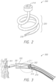
- FIG. 2 illustrates a perspective view of a corkscrew tissue anchor 200 in accordance with one or more embodiments.
- the corkscrew anchor 200 comprises a helical portion 220 that terminates in a tissue-penetrating/piercing tip portion 230, which may advantageously be pointed in shape.
- the corkscrew anchor 200 may further comprise a driver head portion 210, which may be shaped or dimensioned to be engaged by a driver tool of some kind in order to allow for exertion of rotational force on the tissue anchor 200.
- tissue anchor 200 when the pointed tip 230 is placed against biological tissue or other material, rotation of the tissue anchor 200 (e.g., clockwise rotation with respect to the illustrated embodiment) may cause the helical portion 220 of tissue anchor 200 to be screwed into the tissue or material, and thereby become at least partially embedded therein.
- the helical portion 220 may be embedded into the endocardium and/or myocardium layer(s) of the heart.
- tissue anchors such as corkscrew anchors
- tissue anchors may be delivered to a target operational site using a delivery catheter or system.
- Figure 3 illustrates an example delivery system 300 for delivering one or more tissue anchors (301, 302) to a target site.
- tissue anchors may be delivered to a target site for the purpose of embedding the tissue anchor(s) into local biological tissue 20, such as the ventricular wall of the heart, or other biological tissue.
- One or more of the anchors 301, 302 may be coupled to a tethering suture (e.g., 381), which may be used to tether certain biological anatomy as part of a medical procedure.
- the delivery system 300 further comprises one or more driver tools or components 370, which may be configured to engage with a driver head 310 of the tissue anchor 302, to thereby exert force, such as rotational force, thereon to cause the respective anchor to pierce or embed into the target tissue.
- the geometry or form of a corkscrew anchor 302 may lead to entanglements with the suture 381 associated with other tissue anchor 301 or device within the catheter 392.
- the suture 381 may be considered a cinching suture for the tissue anchor 301.
- the geometry or form of the corkscrew anchor e.g., 301 or 302 may result in entanglement with certain other anatomical features external to the catheter 392, such as chordae tendineae, trabeculae carneae, or the like with respect to ventricular procedures in a heart.
- anchor unscrewing or other disengagement may result, particularly under tethering tension that the embedded tissue anchor may be subjected to after implantation thereof.
- visual assessment that a tissue anchor is properly engaged with the target tissue may be difficult, particularly where fluoroscopy or other imaging technology is relied upon for visibility.
- corkscrew anchors can be used in various surgical procedures to attach and/or anchor into biological tissue.
- corkscrew anchors can be used to puncture and/or anchor into the cardiac anatomy.
- Example procedures that may involve corkscrew anchoring can include anchoring of cardiac resynchronization therapy (CRT) leads, annuloplasty device anchoring, among others.
- Corkscrew anchors utilized in medical procedures may be coupled to a suture or other structure, and may serve to anchor thereto. With respect to therapies used to treat structural heart disease, use of corkscrew tissue anchors may present certain advantages and disadvantages.
- corkscrew anchors having traditional configurations can lead to entanglement of the corkscrew with a tethering suture or wire.
- the corkscrew geometry can cause undesirable entanglement, which may occur at least partly within a delivery catheter, or in a heart ventricle, such as entanglement with the chordae tendineae.
- Suture entanglement in the delivery catheter may be a particular risk where multiple anchors are placed using a single catheter, as shown in the diagram of Figure 3 .
- tissue anchoring/piercing devices and/or methods that at least partially resolve one or more of the various issues described above with respect to certain tissue anchoring/piercing devices.
- the present disclosure provides a tissue anchor or piercing device that is associated with a cover feature, which may comprise cloth, polymer film, or the like, wherein such cover at least partially prevents entanglements of the tissue anchor with sutures and/or biological anatomy.
- the cover of the tissue anchor may be configured and/or designed such that, as the tissue anchor is rotated or otherwise pushed into the target tissue, the anchor tip pierces the cover, allowing the anchor to pass therethrough.
- a cover for a tissue anchor comprises one or more radiopaque markers.
- the cover is made of radiopaque material, such that the cover is substantially entirely radiopaque. Where radiopaque material is used in connection with the cover, as the anchor is pushed out of the cover when embedding in tissue, the radiopaque marker(s) may move with respect to the anchor and/or anchor tip.
- the cover may bunch up outside of the target tissue, and therefore the radiopaque features associated therewith may be viewable relative to the anchor embedded in the tissue, thereby providing a visual indication that at least a portion of the anchor has passed through the cover and embedded in tissue.
- a corkscrew tissue anchor device in accordance with embodiments of the present disclosure comprises a swivel feature, which may at least partially prevent twisting of the suture associated with the anchor during deployment of the anchor.
- the swivel feature may comprise an engaging fastener pin or spike feature configured to lock into the cover and/or target tissue to at least partially prevent the backing out or unscrewing of the tissue anchor.
- the cover e.g., cloth and/or film
- the cover may bunch-up, which may serve to create friction to further help prevent the backing-out or unscrewing of the tissue anchor.
- FIGs 4-6 illustrate embodiments of corkscrew tissue anchors having cover features associated therewith accordance with one or more embodiments.
- the tissue anchor devices of Figures 4-6 may comprise certain anti-entanglement, anti-unscrewing, and/or visibility-enhancement features (e.g. features allowing for improved visibility under fluoroscopy), as referenced above.
- corkscrew anchors can be used to attach and/or anchor into cardiac anatomy for various therapies (e.g., CRT lead placement, percutaneous annuloplasty anchoring, etc.).
- corkscrew-type anchors in therapies used to treat, for example, structural heart disease.
- entanglement of corkscrew anchors with sutures and/or biological anatomy can undesirably interfere with the execution of a medical procedure and/or result in physical damage or other harm.
- the helical geometry of corkscrew anchors may facilitate or make possible the entangling of the anchor with a suture, wire, chordae tendineae, or the like.
- solutions of the present disclosure provide a corkscrew anchor that is covered with a cloth or film, such as a polymer film or the like, which may serve to at least partially prevent or reduce the risk of entanglement with other devices or anatomy.
- the anchor device 400 comprises a cloth cover 440, which may provide a sock-like covering that at least partially prevents or reduces the risk of the internal corkscrew anchor geometry (not shown) from becoming entangled with sutures or local anatomy at a target operation site, such as chordae tendineae of a heart ventricle, or the like.
- the diagrams of Figures 4 and 5 show tissue anchor devices having different types of covers.
- the cover 440 may comprise a relatively loosely-woven mesh or fabric
- the cover 540 of the device 500 of Figure 5 may comprise a more tightly-woven fabric, or a polymer film or the like.
- the covers shown in the illustrated embodiments may serve to prevent the corkscrew geometry from entanglement and may allow for the internally-disposed corkscrew anchor to be screwed through, or otherwise penetrate, the distal portion (not shown) of the cover to allow the tissue anchor to embed into the target tissue when approximated thereto.
- the embodiments of Figures 4 and 5 further show radiopaque markers 445, 545 associated with the respective covers of the anchor devices.
- the illustrated embodiments show relatively small radiopaque marker areas, it should be understood that radiopaque or other visibility features associated with a cover of a tissue anchor in accordance with the present disclosure may have any suitable size, shape, or configuration.
- at least part of the cover of a tissue anchor comprises radiopaque fabric.
- the cover is entirely comprised of radiopaque fabric or material.
- radiopaque fabric or material associated with a tissue anchor cover in accordance with the present disclosure may comprise a full circumferential coverage.
- radiopaque markers for tissue anchor covers may generally be associated at least with a distal portion or end of the tissue anchor device. Radiopaque material may be used with tissue anchor covers in accordance with the present disclosure in order to assist in visualization of placement of the tissue anchor under fluoroscopy.
- a cover of a tissue anchor in accordance with the present disclosure comprises fully radiopaque fabric or cloth, wherein the radiopaque characteristic of the cover may allow for visualization of the cover separate from the anchor, which may provide information indicating where the cloth is relative to the tissue anchor and to what extent the tissue anchor is embedded in the target tissue.
- Figure 6 illustrates a side view of a corkscrew tissue anchor device 600 having a cover 640 in accordance with one or more embodiments.
- the cover 640 is configured or designed to cover substantially all of a helical portion 620 of an inner corkscrew form 601 of the anchor device 600.
- the anchor device 600 includes a driver head 610, which may be manipulated to cause the helical portion of the anchor to rotate, thereby embedding the pointed tip 630 of the anchor into target biological tissue.
- the distal pointed end 630 of the inner corkscrew 601 may be caused to puncture and push through the distal end portion of the cover 640, such that the corkscrew passes out of the cover 640 as it enters the target tissue.
- the cover 640 comprises relatively loosely-woven mesh or fabric, such that the pointed tip 630 may pass between the fibers of the mesh or fabric.
- the cover 640 of the anchor device 600 comprises one or more radiopaque marker features or portions 645.
- the radiopaque feature(s) of the cover 640 may advantageously have radiopacity/radiodensity characteristics that provide opacity to the radio wave and/or X-ray portions of the electromagnetic spectrum.
- the radiopaque feature(s) e.g., marker 645
- the radiopaque feature(s) may be configured to inhibit the passage of any desired wavelength/frequency of electromagnetic radiation, such that an imaging technique utilizing a particular frequency/wavelength of radiation that is blocked by the radiopaque feature(s) may be used to visualize or identify such features.
- the radiopaque feature(s) may have a relatively light appearance, providing visual distinction from surrounding matter.
- radiopacifier materials like those listed above may be provided as a filler material according to any suitable or desirable density or loading (e.g., 0-20%, 20-30%, 30-40%, 40-50%, 50-60%, or other density).
- the density of radiopacifier filler in a polymer cover may advantageously be low enough as to not undesirably affect or degrade the polymer's tensile strength.
- the radiopaque marker(s) may show the relative anchor positioning with respect to the cover 640 under fluoroscopy or other imaging mechanism.
- the radiopaque marking 645 and/or portion of the cover 640 may be positioned and/or configured to move relative to the helical portion 620 of the corkscrew anchor 601 when the tip 630 and at least part of the helical portion 620 are engaged with, and twisted into, tissue or other material.
- the cover 640 may become at least partially bunched-up, or drawn proximally/upward, relative to the pointed tip 630 with respect to the orientation illustrated in Figure 6 . Therefore, the relative positioning of the marker portion(s) may change with respect to one or more other features (e.g. metallic features) of the anchor 600. In some embodiments, bunching up of the cover may be caused or facilitated at least in part by an attachment or tightening of the cover 640 at a cinch point 603, which may be generally associated with or proximal end portion of the anchor 600.
- the collar of the cover 640 may be cinched with a strap, band, tie, suture, or the like. In some embodiments, as shown, the cover 640 may be cinched or otherwise attached at or near a proximal driver head feature 610.
- FIG. 7 illustrates a delivery system 700 for one or more tissue anchors in accordance with one or more embodiments.
- a plurality of tissue anchors may be delivered to a target site, such as within a ventricle heart, using a single delivery catheter 792.
- anchors are corkscrew-type anchors, as described in detail above, sutures and/or other components associated with the tissue anchors may become entangled with the corkscrew features of the tissue anchors within the catheter 792 and/or external to the catheter.
- a tissue anchor 702 delivered using a delivery catheter 792 comprises a cover 742 that prevents the corkscrew portion 722 of the tissue anchor 702, which is disposed at least partially within the cover 742, from becoming entangled with, for example, a suture 781, which may be attached to or otherwise associated with another tissue anchor 701.
- a tissue anchor e.g., tissue anchor 701 having a cover feature in accordance with embodiments of the present disclosure
- the internal corkscrew anchor 721 may be approximated to the surface of the target biological tissue 20 and pushed through the cover 741.
- the tip 731 of the tissue anchor 701 into the tissue 20 may cause the tip 731 to pass through the cover 741 and enter the tissue 20. While the pointed tip 731 and/or body 721 of the tissue anchor 701 may embed in the tissue 20, the cover 741 may remain generally external to the tissue, as shown, and may become at least partially bunched-up on the surface of the tissue due to the decreased distance between the attachment point of the cover with the anchor, or other surface or feature of the tissue anchor, and the surface of the tissue 20. For example, at least a portion of the cover 741 may become pinned or bunched between the driver head 711 or other feature of the tissue anchor 701 and the surface of the tissue 20.
- the cover features (741, 742) may further protect sharp points (e.g. 731, 732) of the tissue anchor(s) and/or other features of the tissue anchor(s) from undesirably catching on local anatomy, or components or devices of the implant system, when the tip of the respective anchor does not properly engage with the target tissue. Therefore, the cover at least partially protects the associated anchor from embolizing or getting entangled in chordae tendineae or other anatomy. For example, where a technician or physician is attempting to twist the tissue anchor 701 into the tissue 20, the cover 741 may protect the internal corkscrew features of the anchor 701 from becoming entangled with local anatomy prior to proper engagement of the anchor with the target tissue.
- the cover 741 can collect together or bunch-up. Therefore, where one or more radiopaque markers for marker portions are associated with the cover 741, such marker(s) may experience relative movement with the cover 741 away from the tip 731 and/or helical portion 721 of the anchor 701 generally in the proximal direction.
- the relative movement of the marker(s) and the other portions of the anchor 701 may be visible under fluoroscopy or other imaging technology.
- at least a portion of the corkscrew 721 and/or tip 731 may comprise metal or other material that is visible under fluoroscopy.
- FIG. 8 illustrates a tissue anchor 800 having a cover 840 covering at least a portion of a corkscrew anchor 801, and a suture-holding swivel feature 860 in accordance with one or more embodiments.
- the tissue anchor 800 comprises a corkscrew or helical portion 820 which may be at least initially disposed at least partially within the cover 840, as shown.
- the tissue anchor 800 further comprises a torque driver coupling head feature 810, which may be used to drive the tissue anchor into target biological tissue, such as by twisting or torqueing the driver head 810.
- the cover 840 may comprise any type of cloth/fabric or film.
- the cover 840 may be associated with one or more radiopaque markers or marker portions.
- the marker(s) may be positioned and/or designed to move relative to the corkscrew portion 820 when the corkscrew portion 820 is rotated into target biological tissue.
- the entire cloth or cover 840, or at least a substantial portion thereof, is woven of radiopaque fabric/suture.
- the cover 840 comprises one or more sewn-on platinum iridium markers, or other types of radiopaque features or markers.
- the tissue anchor 800 may further be associated with a suture 881.
- the suture 881 may be configured to connect to the anchor 800, and may be used to connect the anchor 800 to one or more additional anchors, devices, or anatomical features in connection with a surgical procedure.
- the tissue anchor 800 comprises a swivel feature 860, which may be configured and/or designed to at least partially prevent suture entanglement during the application of torque to, or rotation of, the corkscrew anchor 820 and/or driver head 810. That is, the swivel feature 860 may at least partially prevent twisting of the suture 881 during deployment of the tissue anchor 800.
- the swivel feature 860 is coupled to the suture 881, such that the suture 881 may remain substantially stationary relative to the tissue-engagement portion 820 as the tissue-engagement portion 820 of the tissue anchor 800 is wound into the target tissue.
- the swivel feature 860 may comprise an aperture or other attachment or securement mechanism 861 configured and/or dimensioned to hold the suture 881.
- the suture 881 may be slidably held within the aperture or attachment feature 861, such that the suture 881 may be drawn vertically with respect to the orientation of Figure 8 through the swivel feature 861, as necessary or desired.
- the swivel feature 860 may comprise an engagement fastener 862, such as a pin or spike feature, which may be shaped and configured to embed into the cover 840 and/or biological tissue to help prevent backing-out or unscrewing of the helical tissue-engagement portion 820 of the anchor 800.
- the swivel feature 860 may at least partially prevent entanglement of the suture 881 during torque application or twisting of the driver head 810, wherein the spike feature 862 may be configured to engage with the cover 840 and/or target biological tissue to prevent unscrewing.
- the cover 840 may collect or become bunched-up between the driver head 810 (or other attachment or contact point between the cover 840 and the internal anchor 801) and the surface of the target tissue.
- the bunched-up cover 840 when the tissue-engagement portion 820 is penetrated into the target tissue, may create frictional force between the anchor 800 and the surface of the target tissue to help prevent backing-out or unscrewing of the tissue-engagement portion 820 of the anchor.
- a delivery system used to deliver the anchor 800 comprises one or more holder features configured and designed to hold the swivel feature 860 with respect to the driver head 810.
- the driver head 810 may advantageously be allowed to turn, wherein the swivel feature 860 is substantially free relative to the driver head 810, such that rotation of the driver head does not result in a corresponding rotation in the swivel feature 860.
- Such relative independence of the swivel feature 860 and the driver head 810 may help to keep the suture 881 from becoming entangled as the driver head is rotated.
- the spike feature 862 may pierce and/or otherwise engage with the target tissue as the driver head 810 is approximated to the tissue surface.
- the spike feature 862 may help to keep the helical portion 820 of the corkscrew anchor 801 from unscrewing, and may be further assisted in preventing disengagement or unscrewing of the tissue anchor by the cover 840, which may be collected between the driver head 810 and/or swivel feature 860 and the tissue surface.
- the swivel feature 860 may generally be free to rotate independently of the corkscrew anchor 801 and/or driver head 810, when the spike feature 862 is embedded in the target tissue, the swivel feature 860 may thereby further secure the tissue anchor in the implanted/embedded position.
- FIG. 9 illustrates a side view of a tissue anchor 900 in accordance with embodiments of the present disclosure that is coupled to a torque driver 970.
- the torque driver 970 is engaged with a driver head 910 of the tissue anchor device 900.
- the torque driver coupling head 910 may be engaged by the torque driver 970, wherein rotation of the torque driver 970 may thereby be translated to rotation of driver head 910 and anchor 900.
- the tissue anchor 900 may comprise a cover 940 having disposed or contained therein a tissue-embedding anchor, such as a corkscrew-type anchor or the like.
- FIG. 10 illustrates a side view of a tissue anchor device 1000 in accordance with one or more embodiments.
- the tissue anchor device 1000 includes a tissue-engagement portion 1020 having a pointed distal portion 1030, and one or more barbs or other anchoring features 1025.
- the anchor device 1000 further comprises a cover 1040, which may be similar in certain respects to embodiments of tissue anchor covers described above.
- the cover may comprise cloth, fabric, polymer film or braid, or any other type of material designed to cover tissue engagement/anchoring features of the tissue anchor device 1000 to prevent entanglement or contact therewith directly by anatomical or device components.
- the cover 1040 may advantageously be loose enough about the tissue-engagement portion 1020 to allow for the tissue-engagement portion 1020 (e.g.
- the cover 1040 may comprise one or more radiopaque markers or marker portions 1045, which may be similar in certain respects to radiopaque materials and markings/features described in detail herein. At least a portion of the cover 1040 may comprise radiopaque material, fabric, polymer, or the like.
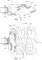
- FIG 11 illustrates the barbed tissue anchor 1000 of Figure 10 implanted in biological tissue 1122 in accordance with one or more embodiments.
- the tissue engagement portion 1020 As the tissue engagement portion 1020, which is disposed initially internal to the cover 1040, is pressed into the target biological tissue, the tissue engagement portion 1020 may pierce the distal portion of the cover 1040 and pass therethrough into the tissue 1122.
- the cover 1040 may not be allowed or inclined to pass into the biological tissue 1122, and may rather collect or bunch-up external to the biological tissue 1122 between the surface of the tissue and a point of attachment of the cover 1040 to the proximal portion of the tissue anchor device 1000, or between the surface of the tissue and a surface or feature of the tissue anchor 1000 at least partly opposite-facing with respect to the tissue surface.
- the cover 1040 comprises one or more radiopaque markers, or other portions of radiopaque material (e.g.
- the cover 1040 may comprise or consist of radiopaque fabric), such radiopaque feature(s) may advantageously allow for visibility of the relative motion of the cover 1040 to the tissue engagement portion 1020, which may thereby provide an indication of the extent to which the tissue engagement portion 1020 is embedded into the target tissue 1122.
- FIG. 12 illustrates a side view of a tissue-penetrating device 1200 in accordance with one or more embodiments.
- the device 1200 comprises a tissue-engagement or penetrating portion 1220, which may comprise a pointed distal portion 1230 configured to pierce target biological tissue, and further comprises a cover 1240 configured to at least partially enclose the tissue-engagement portion 1220 prior to embedding thereof in the target biological tissue.
- the tissue-engagement portion 1220 comprises a hypodermic needle or tube, forming an internal lumen 1229, which may be used to introduce certain fluids or materials into the target tissue according to a medical operation or procedure.
- the lumen 1229 may terminate in a discharge orifice, as shown, for discharging fluid or other material into the target tissue.
- the cover 1240 may comprise cloth, fabric, polymer film or braid, or any other type of material designed to cover the tissue-engagement features of the tissue anchor device 1200 to at least partly prevent entanglements or contact therewith directly by anatomical or device components.
- the cover 1240 may advantageously be loose enough about the tissue engagement portion 1220 to allow for the tissue engagement portion 1220 (e.g. beginning at the point at the distal end 1230) to pierce and/or pass through the distal portion of the cover 1240 when the tissue anchor device 1200 is pressed against target tissue to embed the tissue engagement portion 1220 therein.
- the cover 1240 may comprise one or more radiopaque markers are marker portions 1245, which may be similar in certain respects to radiopaque materials and markings described in detail herein. At least a portion of the cover 1240 may comprise radiopaque material, fabric, polymer, or the like.
- FIG. 13 illustrates the tissue-penetrating device 1200 of Figure 12 embedded in biological tissue 1322 in accordance with more embodiments.
- the tissue-engagement portion 1220 which is disposed initially internal to the cover 1240, is pressed into the target biological tissue, the tissue-engagement portion 1220 may pierce the distal portion of the cover 1240 and pass therethrough into the tissue 1322.
- the cover 1240 may not be allowed or inclined to pass into the biological tissue 1322, and may rather collect or bunch-up external to the biological tissue 1322 between the surface of the tissue and a point of attachment of the cover 1240 to the proximal portion of the tissue-penetrating device 1200, and/or between the surface or feature of the tissue and a surface of the tissue-penetrating device 1200 that is at least partly opposite-facing with respect to the tissue surface.
- the cover 1240 comprises one or more radiopaque markers, or other portions of radiopaque material (e.g.
- the cover 1240 may comprise or consist of radiopaque fabric), such radiopaque feature(s) may advantageously allow for visibility of the relative displacement or movement of the cover 1240 to the tissue-engagement portion 1220, which may thereby provide an indication of the extent to which the tissue engagement portion 1220 is embedded into the target tissue 1322.
- Figure 14 is a flow diagram illustrating a process 1400 for anchoring to or penetrating or embedding in biological tissue or other material in accordance with one or more embodiments.
- the process 1400 may advantageously result in reduced entanglement risk of anchor or tissue-penetrating devices within the delivery catheter and/or improved visibility of tissue engagement using fluoroscopy, as described in detail herein.
- the process 1400 involves advancing a delivery system for one or more tissue anchors to a target location.
- the one or more tissue anchors may advantageously comprise respective covers, as described in detail herein.
- the one or more tissue anchors comprises a corkscrew anchor having a cloth or film covering to prevent entanglement.
- the process 1400 involves deploying a tissue anchor from the delivery system and approximating a tissue anchor to a target tissue surface.
- the cover may be configured to bunch-up as an inner corkscrew anchor is twisted.
- the process 1400 involves passing the tissue-engagement portion of the tissue anchor through a distal portion of the cover and into the target tissue, thereby causing the cover to collect and/or bunch-up on the surface of the target tissue.
- the cover may comprise a cloth covering for a tissue-engagement portion of the tissue anchor, and may further have one or more radiopaque markers for visibility of the anchor engaging with tissue, as described above.
- the process 1400 involves utilizing fluoroscopy (e.g., X-ray) or other imaging technology to view the tissue engagement portion of the tissue anchor device and one or more radiopaque markers or portions of the tissue anchor device to determine that the tissue engagement portion of the tissue anchor device has properly engaged or embedded into the target tissue.
- fluoroscopy e.g., X-ray
- radiopaque markers or portions of the tissue anchor device to determine that the tissue engagement portion of the tissue anchor device has properly engaged or embedded into the target tissue.
- the process 1400 involves embedding a spike feature of a swivel feature of the tissue anchor device into the target tissue and/or cover to thereby secure the tissue engagement portion in the embedded position within the target tissue and prevent disengagement.
- the tissue anchor may advantageously comprise a swivel feature on a corkscrew anchor that prevents suture entanglement.
- tissue anchors Although Figure 14 and the accompanying description describe tissue anchors, it should be understood that the steps of the process 1400 may relate to other types of tissue-penetrating devices, and description of tissue anchors should be considered to apply to other tissue-penetrating devices as well, such as hypodermic needles and tubes.
- tissue anchors should be considered to apply to other tissue-penetrating devices as well, such as hypodermic needles and tubes.
- certain devices and processes are disclosed herein context of anchoring to biological tissue, it should be understood that devices and processes disclosed herein are applicable for anchoring into other types of materials, including nonbiological materials.
- indefinite articles may indicate “one or more” rather than “one.”
- an operation performed "based on” a condition or event may also be performed based on one or more other conditions or events not explicitly recited.
- spatially relative terms “outer,” “inner,” “upper,” “lower,” “below,” “above,” “vertical,” “horizontal,” and similar terms, may be used herein for ease of description to describe the relations between one element or component and another element or component as illustrated in the drawings. It will be understood that the spatially relative terms are intended to encompass different orientations of the device in use or operation, in addition to the orientation depicted in the drawings. For example, in the case where a device shown in the drawing is turned over, the device positioned “below” or “beneath” another device may be placed “above” another device. Accordingly, the illustrative term “below” may include both the lower and upper positions. The device may also be oriented in the other direction, and thus the spatially relative terms may be interpreted differently depending on the orientations.
Landscapes
- Health & Medical Sciences (AREA)
- Life Sciences & Earth Sciences (AREA)
- Surgery (AREA)
- Cardiology (AREA)
- Animal Behavior & Ethology (AREA)
- General Health & Medical Sciences (AREA)
- Biomedical Technology (AREA)
- Heart & Thoracic Surgery (AREA)
- Engineering & Computer Science (AREA)
- Veterinary Medicine (AREA)
- Public Health (AREA)
- Medical Informatics (AREA)
- Nuclear Medicine, Radiotherapy & Molecular Imaging (AREA)
- Molecular Biology (AREA)
- Rheumatology (AREA)
- Oral & Maxillofacial Surgery (AREA)
- Transplantation (AREA)
- Vascular Medicine (AREA)
- Surgical Instruments (AREA)
- Prostheses (AREA)
Abstract
Description
- This application claims priority to
U.S. Provisional Application No. 62/669,622, filed May 10, 2018 - The present disclosure generally relates to the field of biological tissue anchors and tissue-piercing devices. Tissue anchors and other devices for piercing and/or embedding in tissue or other material are used for various applications. The shape and/or features of such devices can lead to entanglement and visibility issues.
- In some implementations, the present disclosure relates to a tissue anchor comprising a driver head associated with a proximal portion of the tissue anchor, a pointed tip portion associated with a distal portion of the tissue anchor, a tissue-engagement portion disposed between the driver head and the pointed tip portion, and a cover configured to cover at least a portion of the tissue-engagement portion.
- In certain embodiments, the pointed tip portion is disposed within the cover. The cover may comprise cloth and/or polymer film. In some embodiments, the tissue anchor further comprises a swivel feature. For example, the swivel feature may include a suture-holding feature and/or may comprise a fastener configured to fasten to one or more of the cover and target biological tissue. The tissue anchor may further comprise a radiopaque material associated with the cover. In some embodiments, the tissue-engagement portion has a helical form. In some embodiments, the cover is configured to bunch up as the helical tissue-engagement portion passes through the cover and into tissue. The helical tissue-engagement portion may be configured to pass through the cover as the driver head is rotated and pressed against biological tissue. For example, the pointed tip portion may be configured to puncture the cover and at least partially pass therethrough when pressed against the biological tissue. In some embodiments, the tissue-engagement portion comprises one or more barbs and/or a hypodermic tube. In some embodiments, the tissue anchor further comprises a suture that is secured to one or more of the driver head and the helical tissue-engagement portion.
- In some implementations, the present disclosure relates to a method for anchoring into tissue. The method comprises approximating a tissue anchor to tissue, the tissue anchor being at least partially encapsulated in a cover, engaging a driver head portion of the tissue anchor, puncturing at least one of the cover of the tissue anchor and the tissue with a pointed tip portion of the tissue anchor and rotating the driver head portion to advance at least a portion of a corkscrew portion of the tissue anchor into the tissue.
- The method may further comprise providing a catheter containing the tissue anchor, delivering the catheter into a ventricle of a heart associated with the tissue, and expelling the tissue anchor from the catheter. For example, the method further comprises carrying another tissue anchor having another cover within the catheter, wherein the cover of the other tissue anchor prevents entanglement of another corkscrew portion of the other tissue anchor with a suture coupled to the tissue anchor. In some embodiments, the method further comprises visually determining that the corkscrew portion of the tissue anchor has advanced into the tissue from external to a body associated with the tissue. For example, visually determining may involve identifying one or more radiopaque markings associated with the cover using X-ray imaging. In some embodiments, rotating the driver head portion causes the cover to gather between the tissue and the driver head.
- In some implementations, the present disclosure relates to a system comprising a delivery catheter, a corkscrew tissue anchor having a proximal head portion and a distal pointed portion, a suture coupled to the corkscrew tissue anchor, and a cover covering at least part of the corkscrew tissue anchor. The cover may include one or more visual markers identifiable using radiation imaging. The system may further comprise a swivel fastener coupled to the corkscrew tissue anchor and configured to fasten to the cover.
- Various embodiments are depicted in the accompanying drawings for illustrative purposes and should in no way be interpreted as limiting the scope of the inventions. In addition, various features of different disclosed embodiments can be combined to form additional embodiments, which are part of this disclosure. Throughout the drawings, reference numbers may be reused to indicate correspondence between reference elements.
-
Figure 1 provides a cross-sectional view of a human heart. -
Figure 2 provides a perspective view of a tissue anchor in accordance with one or more embodiments. -
Figure 3 illustrates a delivery system for one or more tissue anchors in accordance with one or more embodiments. -
Figure 4 illustrates a tissue anchor having a cover in accordance with one or more embodiments. -
Figure 5 illustrates a tissue anchor having a cover in accordance with one or more embodiments. -
Figure 6 illustrates a tissue anchor having a cover in accordance with one or more embodiments. -
Figure 7 illustrates a delivery system for one or more tissue anchors in accordance with one or more embodiments. -
Figure 8 illustrates a tissue anchor having a cover and a swivel feature in accordance with one or more embodiments. -
Figure 9 illustrates a torque driver engaged with a tissue anchor in accordance with one or more embodiments. -
Figure 10 illustrates a tissue anchor having a cover in accordance with one or more embodiments. -
Figure 11 illustrates a tissue anchor embedded in tissue in accordance with one or more embodiments. -
Figure 12 illustrates a tissue-piercing device having a cover in accordance with one or more embodiments. -
Figure 13 illustrates a tissue-piercing device embedded in tissue in accordance with one or more embodiments. -
Figure 14 is a flow diagram illustrating a process for placing a tissue anchor in accordance with one or more embodiments. - The headings provided herein are for convenience only and do not necessarily affect the scope or meaning of the claimed invention.
- Although certain preferred embodiments and examples are disclosed below, inventive subject matter extends beyond the specifically disclosed embodiments to other alternative embodiments and/or uses and to modifications and equivalents thereof. Thus, the scope of the claims that may arise herefrom is not limited by any of the particular embodiments described below. For example, in any method or process disclosed herein, the acts or operations of the method or process may be performed in any suitable sequence and are not necessarily limited to any particular disclosed sequence. Various operations may be described as multiple discrete operations in turn, in a manner that may be helpful in understanding certain embodiments; however, the order of description should not be construed to imply that these operations are order dependent. Additionally, the structures, systems, and/or devices described herein may be embodied as integrated components or as separate components. For purposes of comparing various embodiments, certain aspects and advantages of these embodiments are described. Not necessarily all such aspects or advantages are achieved by any particular embodiment. Thus, for example, various embodiments may be carried out in a manner that achieves or optimizes one advantage or group of advantages as taught herein without necessarily achieving other aspects or advantages as may also be taught or suggested herein.
- The present disclosure provides systems, devices, and methods relating to entanglement-resistant tissue anchors and other tissue-piercing/penetrating devices, which may be used for certain medical procedures, or for other applications. Certain of the disclosed embodiments further provide tissue anchoring and/or puncturing devices having certain anti-unscrewing or anti-disengagement features associated therewith. Devices disclosed herein may be designed or configured to be embedded in, or otherwise attached, to biological tissue. However, it should be understood that principles disclosed herein may be applicable to devices and methods for embedding or securing to non-biological tissue as well. In some embodiments, the present disclosure relates to corkscrew-type anchors, which are described in detail herein. However, it should be understood that the disclosed principles may be applicable to other types of tissue anchors or tissue-piercing devices (e.g., hypodermic needles or tubes, or the like). Therefore, description herein of corkscrew-type anchors is applicable to other types of anchors and devices, including devices that do not have a corkscrew form or shape.
- Corkscrew anchors may be used to attach or anchor into biological tissue. For example, in connection with certain cardiac procedures, tissue anchors or the like may be used to embed in or otherwise secure to cardiac anatomy, which may be useful for various therapies. For example, cardiac resynchronization therapy (CRT), percutaneous angioplasty, or other therapies may utilize one or more corkscrew anchors, or other types of anchors, in some implementations.
- Corkscrew and other types of tissue anchors or tissue-puncturing devices, may be used in connection with various medical procedures, including cardiac operations. For convenience, in some contexts, the present disclosure describes embodiments in the context of cardiac operations. However, it should be understood that the disclosed embodiments may be implemented in connection with any type of medical procedure. To provide context for the disclosure herein relating to cardiac operations,
Figure 1 and the associated description show and describe a human heart. In humans and other vertebrate animals, the heart generally comprises a muscular organ having four pumping chambers, wherein the flow thereof is at least partially controlled by various heart valves, namely, the aortic, mitral (or bicuspid), tricuspid, and pulmonary valves. The valves may be configured to open and close in response to a pressure gradient present during various stages of the cardiac cycle (e.g., relaxation and contraction) to at least partially control the flow of blood to a respective region of the heart and/or to blood vessels (e.g., pulmonary, aorta, etc.). -
Figure 1 illustrates an example representation of a heart 1 having various features relevant to certain embodiments of the present inventive disclosure. The heart 1 includes four chambers, namely theleft atrium 2, theleft ventricle 3, the right ventricle 4, and theright atrium 5. A wall of muscle 17, referred to as the septum, separates theleft 2 and right 5 atria and theleft 3 and right 4 ventricles. The heart 1 further includes four valves for aiding the circulation of blood therein, including thetricuspid valve 8, which separates theright atrium 5 from the right ventricle 4. Dysfunction of a heart valve may be treated using various procedures that involve anchoring to cardiac tissue, which may be used to provide a tethering force for valve correction. Tissue anchors in accordance with the present disclosure may advantageously provide for tissue anchoring for valve or other cardiac correction procedures with improved visibility and/or anti-entanglement features, as described in detail below. Tissue anchoring for cardiac operations may involve anchoring to the ventricular wall or septum. - The
tricuspid valve 8 may generally have three cusps or leaflets and may generally close during ventricular contraction (i.e., systole) and open during ventricular expansion (i.e., diastole). The valves of the heart 1 further include thepulmonary valve 9, which separates the right ventricle 4 from thepulmonary artery 11, and may be configured to open during systole so that blood may be pumped toward the lungs, and close during diastole to prevent blood from leaking back into the heart from the pulmonary artery. Thepulmonary valve 9 generally has three cusps/leaflets, wherein each one may have a crescent-type shape. The heart 1 further includes the mitral valve 6, which generally has two cusps/leaflets and separates theleft atrium 2 from theleft ventricle 3. The mitral valve 6 may generally be configured to open during diastole so that blood in theleft atrium 2 can flow into theleft ventricle 3, and advantageously close during diastole to prevent blood from leaking back into theleft atrium 2. The aortic valve 7 separates theleft ventricle 3 from theaorta 12. The aortic valve 7 is configured to open during systole to allow blood leaving theleft ventricle 3 to enter theaorta 12, and close during diastole to prevent blood from leaking back into theleft ventricle 3. - Heart valves may generally comprise a relatively dense fibrous ring, referred to herein as the annulus, as well as a plurality of leaflets or cusps attached to the annulus. Generally, the size of the leaflets or cusps may be such that when the heart contracts the resulting increased blood pressure produced within the corresponding heart chamber forces the leaflets at least partially open to allow flow from the heart chamber. As the pressure in the heart chamber subsides, the pressure in the subsequent chamber or blood vessel may become dominant and press back against the leaflets. As a result, the leaflets/cusps come in apposition to each other, thereby closing the flow passage.
- The atrioventricular (i.e., mitral and tricuspid) heart valves may further comprise a collection of chordae tendineae and papillary muscles for securing the leaflets of the respective valves to promote and/or facilitate proper coaptation of the valve leaflets and prevent prolapse thereof. The papillary muscles, for example, may generally comprise finger-like projections from the ventricle wall. With respect to the
tricuspid valve 8, the normal tricuspid valve may comprise three leaflets (two shown inFigure 1 ) and three corresponding papillary muscles 10 (two shown inFigure 1 ). The leaflets of the tricuspid valve may be referred to as the anterior, posterior and septal leaflets, respectively. The valve leaflets are connected to the papillary muscles by thechordae tendineae 11, which are disposed in the right ventricle 4 along with thepapillary muscles 10. Although tricuspid valves are described herein as comprising three leaflets, it should be understood that tricuspid valves may occur with two or four leaflets in certain patients and/or conditions; the principles relating to papillary muscle adjustment disclosed herein are applicable to atrioventricular valves having any number of leaflets and/or papillary muscles associated therewith. - The right ventricular
papillary muscles 10 originate in the right ventricle wall, and attach to the anterior, posterior and septal leaflets of the tricuspid valve, respectively, via thechordae tendineae 11. Thepapillary muscles 10 of the right ventricle 4 may have variable anatomy; the anterior papillary may generally be the most prominent of the papillary muscles. Thepapillary muscles 10 may serve to secure the leaflets of thetricuspid valve 8 to prevent prolapsing of the leaflets into theright atrium 5 during ventricular systole. Tricuspid regurgitation can be the result of papillary dysfunction or chordae rupture. - With respect to the mitral valve 6, a normal mitral valve may comprise two leaflets (anterior and posterior) and two corresponding
papillary muscles 15. Thepapillary muscles 15 originate in the left ventricle wall and project into theleft ventricle 3. Generally, the anterior leaflet may cover approximately two-thirds of the valve annulus. Although the anterior leaflet covers a greater portion of the annulus, the posterior leaflet may comprise a larger surface area in certain anatomies. - The valve leaflets of the mitral valve 6 may be prevented from prolapsing into the
left atrium 2 by the action of thechordae tendineae 16 tendons connecting the valve leaflets to thepapillary muscles 15. The relativelyinelastic chordae tendineae 16 are attached at one end to thepapillary muscles 15 and at the other to the valve leaflets; chordae tendineae from each of thepapillary muscles 15 are attached to a respective leaflet of the mitral valve 6. Thus, when theleft ventricle 3 contracts, the intraventricular pressure forces the valve to close, while thechordae tendineae 16 keep the leaflets coapting together and prevent the valve from opening in the wrong direction, thereby preventing blood to flow back to theleft atrium 2. The various chords of the chordae tendineae may have different thicknesses, wherein relatively thinner chords are attached to the free leaflet margin, while relatively thicker chords (e.g., strut chords) are attached farther away from the free margin. - Although certain embodiments are described herein in the context of cardiac operations, it should be understood that such description is applicable to other types of biological tissue and/or procedures, as well as certain non-biological applications.
-
Figure 2 illustrates a perspective view of acorkscrew tissue anchor 200 in accordance with one or more embodiments. Thecorkscrew anchor 200 comprises ahelical portion 220 that terminates in a tissue-penetrating/piercingtip portion 230, which may advantageously be pointed in shape. Thecorkscrew anchor 200 may further comprise adriver head portion 210, which may be shaped or dimensioned to be engaged by a driver tool of some kind in order to allow for exertion of rotational force on thetissue anchor 200. Generally, when thepointed tip 230 is placed against biological tissue or other material, rotation of the tissue anchor 200 (e.g., clockwise rotation with respect to the illustrated embodiment) may cause thehelical portion 220 oftissue anchor 200 to be screwed into the tissue or material, and thereby become at least partially embedded therein. For example, with respect to a cardiac operation, thehelical portion 220 may be embedded into the endocardium and/or myocardium layer(s) of the heart. - Corkscrew anchors and/or other types of tissue anchors may be used to treat structural heart disease, such as heart valve dysfunction, ventricular dilation, and/or the like. Generally, tissue anchors, such as corkscrew anchors, may be delivered to a target operational site using a delivery catheter or system.
Figure 3 illustrates anexample delivery system 300 for delivering one or more tissue anchors (301, 302) to a target site. For example, one or more tissue anchors may be delivered to a target site for the purpose of embedding the tissue anchor(s) into localbiological tissue 20, such as the ventricular wall of the heart, or other biological tissue. One or more of theanchors delivery system 300 further comprises one or more driver tools orcomponents 370, which may be configured to engage with adriver head 310 of thetissue anchor 302, to thereby exert force, such as rotational force, thereon to cause the respective anchor to pierce or embed into the target tissue. - Where a
single delivery catheter 392 is used to transport a plurality of tissue anchors and/or sutures, as shown, the geometry or form of acorkscrew anchor 302 may lead to entanglements with thesuture 381 associated withother tissue anchor 301 or device within thecatheter 392. Thesuture 381 may be considered a cinching suture for thetissue anchor 301. In addition, the geometry or form of the corkscrew anchor (e.g., 301 or 302) may result in entanglement with certain other anatomical features external to thecatheter 392, such as chordae tendineae, trabeculae carneae, or the like with respect to ventricular procedures in a heart. In addition to issues relating to entanglement of corkscrew anchors, and/or other types of tissue anchors or devices, anchor unscrewing or other disengagement may result, particularly under tethering tension that the embedded tissue anchor may be subjected to after implantation thereof. In addition, with respect to medical procedures in which the target operational site is visually obscured with respect to the operating physician, visual assessment that a tissue anchor is properly engaged with the target tissue may be difficult, particularly where fluoroscopy or other imaging technology is relied upon for visibility. - As referenced above, corkscrew anchors can be used in various surgical procedures to attach and/or anchor into biological tissue. For example, with respect to certain cardiac procedures, corkscrew anchors can be used to puncture and/or anchor into the cardiac anatomy. Example procedures that may involve corkscrew anchoring can include anchoring of cardiac resynchronization therapy (CRT) leads, annuloplasty device anchoring, among others. Corkscrew anchors utilized in medical procedures may be coupled to a suture or other structure, and may serve to anchor thereto. With respect to therapies used to treat structural heart disease, use of corkscrew tissue anchors may present certain advantages and disadvantages. For example, use of corkscrew anchors having traditional configurations can lead to entanglement of the corkscrew with a tethering suture or wire. The corkscrew geometry can cause undesirable entanglement, which may occur at least partly within a delivery catheter, or in a heart ventricle, such as entanglement with the chordae tendineae. Suture entanglement in the delivery catheter may be a particular risk where multiple anchors are placed using a single catheter, as shown in the diagram of
Figure 3 . - The present disclosure provides tissue anchoring/piercing devices and/or methods that at least partially resolve one or more of the various issues described above with respect to certain tissue anchoring/piercing devices. In some embodiments, the present disclosure provides a tissue anchor or piercing device that is associated with a cover feature, which may comprise cloth, polymer film, or the like, wherein such cover at least partially prevents entanglements of the tissue anchor with sutures and/or biological anatomy. Although certain embodiments are described herein in the context of tissue anchor devices, it should be understood that the principles disclosed herein are applicable to other types of tissue-piercing devices, such as hypodermic needles/tubes. The cover of the tissue anchor may be configured and/or designed such that, as the tissue anchor is rotated or otherwise pushed into the target tissue, the anchor tip pierces the cover, allowing the anchor to pass therethrough. In some embodiments, a cover for a tissue anchor comprises one or more radiopaque markers. In certain embodiments, the cover is made of radiopaque material, such that the cover is substantially entirely radiopaque. Where radiopaque material is used in connection with the cover, as the anchor is pushed out of the cover when embedding in tissue, the radiopaque marker(s) may move with respect to the anchor and/or anchor tip. For example, with respect to a corkscrew anchor, as the corkscrew anchor is twisted into the target tissue, the cover may bunch up outside of the target tissue, and therefore the radiopaque features associated therewith may be viewable relative to the anchor embedded in the tissue, thereby providing a visual indication that at least a portion of the anchor has passed through the cover and embedded in tissue.
- In some embodiments, a corkscrew tissue anchor device in accordance with embodiments of the present disclosure comprises a swivel feature, which may at least partially prevent twisting of the suture associated with the anchor during deployment of the anchor. For example, the swivel feature may comprise an engaging fastener pin or spike feature configured to lock into the cover and/or target tissue to at least partially prevent the backing out or unscrewing of the tissue anchor. Furthermore, as the corkscrew anchor is twisted into the target tissue, the cover (e.g., cloth and/or film) may bunch-up, which may serve to create friction to further help prevent the backing-out or unscrewing of the tissue anchor.
-
Figures 4-6 illustrate embodiments of corkscrew tissue anchors having cover features associated therewith accordance with one or more embodiments. The tissue anchor devices ofFigures 4-6 may comprise certain anti-entanglement, anti-unscrewing, and/or visibility-enhancement features (e.g. features allowing for improved visibility under fluoroscopy), as referenced above. As described above, corkscrew anchors can be used to attach and/or anchor into cardiac anatomy for various therapies (e.g., CRT lead placement, percutaneous annuloplasty anchoring, etc.). - As referenced above, certain advantages and/or disadvantages may be associated with the use of corkscrew-type anchors in therapies used to treat, for example, structural heart disease. For example, entanglement of corkscrew anchors with sutures and/or biological anatomy (e.g., ventricular anatomy of a heart) can undesirably interfere with the execution of a medical procedure and/or result in physical damage or other harm. Generally, the helical geometry of corkscrew anchors may facilitate or make possible the entangling of the anchor with a suture, wire, chordae tendineae, or the like. As shown in the embodiments of
Figures 4-6 , in certain embodiments, solutions of the present disclosure provide a corkscrew anchor that is covered with a cloth or film, such as a polymer film or the like, which may serve to at least partially prevent or reduce the risk of entanglement with other devices or anatomy. - With respect to
Figure 4 , theanchor device 400 comprises acloth cover 440, which may provide a sock-like covering that at least partially prevents or reduces the risk of the internal corkscrew anchor geometry (not shown) from becoming entangled with sutures or local anatomy at a target operation site, such as chordae tendineae of a heart ventricle, or the like. The diagrams ofFigures 4 and 5 show tissue anchor devices having different types of covers. For example, with respect toFigure 4 , thecover 440 may comprise a relatively loosely-woven mesh or fabric, whereas thecover 540 of thedevice 500 ofFigure 5 may comprise a more tightly-woven fabric, or a polymer film or the like. The covers shown in the illustrated embodiments may serve to prevent the corkscrew geometry from entanglement and may allow for the internally-disposed corkscrew anchor to be screwed through, or otherwise penetrate, the distal portion (not shown) of the cover to allow the tissue anchor to embed into the target tissue when approximated thereto. The embodiments ofFigures 4 and 5 further showradiopaque markers -
Figure 6 illustrates a side view of a corkscrewtissue anchor device 600 having acover 640 in accordance with one or more embodiments. In certain embodiments, thecover 640 is configured or designed to cover substantially all of ahelical portion 620 of aninner corkscrew form 601 of theanchor device 600. Theanchor device 600 includes adriver head 610, which may be manipulated to cause the helical portion of the anchor to rotate, thereby embedding thepointed tip 630 of the anchor into target biological tissue. In certain embodiments, as the corkscrewanchor driver head 610 and/or innerhelical portion 620 is wound or rotated and approximated to the target biological tissue, the distalpointed end 630 of theinner corkscrew 601 may be caused to puncture and push through the distal end portion of thecover 640, such that the corkscrew passes out of thecover 640 as it enters the target tissue. In some embodiments, thecover 640 comprises relatively loosely-woven mesh or fabric, such that thepointed tip 630 may pass between the fibers of the mesh or fabric. - The
cover 640 of theanchor device 600 comprises one or more radiopaque marker features orportions 645. The radiopaque feature(s) of thecover 640 may advantageously have radiopacity/radiodensity characteristics that provide opacity to the radio wave and/or X-ray portions of the electromagnetic spectrum. It should be understood that the radiopaque feature(s) (e.g., marker 645) may be configured to inhibit the passage of any desired wavelength/frequency of electromagnetic radiation, such that an imaging technique utilizing a particular frequency/wavelength of radiation that is blocked by the radiopaque feature(s) may be used to visualize or identify such features. For example, in a radiograph, the radiopaque feature(s) may have a relatively light appearance, providing visual distinction from surrounding matter. The radiopaque features of embodiments disclosed herein may comprise any type of material, such as one or more of platinum, iridium, barium, iodine, titanium, tungsten, barium sulfate, bismuth compounds, zirconium oxide, or other material or radiopacifier with relatively high electron density contrast. For polymer covers, radiopacifier materials like those listed above may be provided as a filler material according to any suitable or desirable density or loading (e.g., 0-20%, 20-30%, 30-40%, 40-50%, 50-60%, or other density). The density of radiopacifier filler in a polymer cover may advantageously be low enough as to not undesirably affect or degrade the polymer's tensile strength. - The radiopaque marker(s) may show the relative anchor positioning with respect to the
cover 640 under fluoroscopy or other imaging mechanism. For example, theradiopaque marking 645 and/or portion of thecover 640 may be positioned and/or configured to move relative to thehelical portion 620 of thecorkscrew anchor 601 when thetip 630 and at least part of thehelical portion 620 are engaged with, and twisted into, tissue or other material. For example, as theanchor 600 is wound, such that thecorkscrew anchor 601 pierces and/or passes through the distal end of thecover 640, thecover 640 may become at least partially bunched-up, or drawn proximally/upward, relative to thepointed tip 630 with respect to the orientation illustrated inFigure 6 . Therefore, the relative positioning of the marker portion(s) may change with respect to one or more other features (e.g. metallic features) of theanchor 600. In some embodiments, bunching up of the cover may be caused or facilitated at least in part by an attachment or tightening of thecover 640 at acinch point 603, which may be generally associated with or proximal end portion of theanchor 600. The collar of thecover 640 may be cinched with a strap, band, tie, suture, or the like. In some embodiments, as shown, thecover 640 may be cinched or otherwise attached at or near a proximaldriver head feature 610. -
Figure 7 illustrates adelivery system 700 for one or more tissue anchors in accordance with one or more embodiments. As shown, in some systems, a plurality of tissue anchors may be delivered to a target site, such as within a ventricle heart, using asingle delivery catheter 792. Where such anchors are corkscrew-type anchors, as described in detail above, sutures and/or other components associated with the tissue anchors may become entangled with the corkscrew features of the tissue anchors within thecatheter 792 and/or external to the catheter. As shown, in some embodiments, atissue anchor 702 delivered using adelivery catheter 792 comprises acover 742 that prevents thecorkscrew portion 722 of thetissue anchor 702, which is disposed at least partially within thecover 742, from becoming entangled with, for example, asuture 781, which may be attached to or otherwise associated with anothertissue anchor 701. When a tissue anchor (e.g., tissue anchor 701) having a cover feature in accordance with embodiments of the present disclosure is deployed from thedelivery catheter 792, theinternal corkscrew anchor 721 may be approximated to the surface of the targetbiological tissue 20 and pushed through thecover 741. For example, as described above, rotating or otherwise embedding the tip 731 of thetissue anchor 701 into thetissue 20 may cause the tip 731 to pass through thecover 741 and enter thetissue 20. While the pointed tip 731 and/orbody 721 of thetissue anchor 701 may embed in thetissue 20, thecover 741 may remain generally external to the tissue, as shown, and may become at least partially bunched-up on the surface of the tissue due to the decreased distance between the attachment point of the cover with the anchor, or other surface or feature of the tissue anchor, and the surface of thetissue 20. For example, at least a portion of thecover 741 may become pinned or bunched between thedriver head 711 or other feature of thetissue anchor 701 and the surface of thetissue 20. - In addition to preventing entanglement with sutures and other components within the delivery catheter, the cover features (741, 742) may further protect sharp points (e.g. 731, 732) of the tissue anchor(s) and/or other features of the tissue anchor(s) from undesirably catching on local anatomy, or components or devices of the implant system, when the tip of the respective anchor does not properly engage with the target tissue. Therefore, the cover at least partially protects the associated anchor from embolizing or getting entangled in chordae tendineae or other anatomy. For example, where a technician or physician is attempting to twist the
tissue anchor 701 into thetissue 20, thecover 741 may protect the internal corkscrew features of theanchor 701 from becoming entangled with local anatomy prior to proper engagement of the anchor with the target tissue. - As shown with respect to the
tissue anchor 701, once the anchor passes through thecover 741 and engages with thetissue 20, thecover 741 can collect together or bunch-up. Therefore, where one or more radiopaque markers for marker portions are associated with thecover 741, such marker(s) may experience relative movement with thecover 741 away from the tip 731 and/orhelical portion 721 of theanchor 701 generally in the proximal direction. The relative movement of the marker(s) and the other portions of theanchor 701 may be visible under fluoroscopy or other imaging technology. For example, at least a portion of thecorkscrew 721 and/or tip 731 may comprise metal or other material that is visible under fluoroscopy. -
Figure 8 illustrates atissue anchor 800 having acover 840 covering at least a portion of acorkscrew anchor 801, and a suture-holdingswivel feature 860 in accordance with one or more embodiments. Thetissue anchor 800 comprises a corkscrew orhelical portion 820 which may be at least initially disposed at least partially within thecover 840, as shown. Thetissue anchor 800 further comprises a torque drivercoupling head feature 810, which may be used to drive the tissue anchor into target biological tissue, such as by twisting or torqueing thedriver head 810. Thecover 840 may comprise any type of cloth/fabric or film. Thecover 840 may be associated with one or more radiopaque markers or marker portions. The marker(s) may be positioned and/or designed to move relative to thecorkscrew portion 820 when thecorkscrew portion 820 is rotated into target biological tissue. In some embodiments, the entire cloth or cover 840, or at least a substantial portion thereof, is woven of radiopaque fabric/suture. In some embodiments, thecover 840 comprises one or more sewn-on platinum iridium markers, or other types of radiopaque features or markers. - The
tissue anchor 800 may further be associated with asuture 881. Thesuture 881 may be configured to connect to theanchor 800, and may be used to connect theanchor 800 to one or more additional anchors, devices, or anatomical features in connection with a surgical procedure. Thetissue anchor 800 comprises aswivel feature 860, which may be configured and/or designed to at least partially prevent suture entanglement during the application of torque to, or rotation of, thecorkscrew anchor 820 and/ordriver head 810. That is, theswivel feature 860 may at least partially prevent twisting of thesuture 881 during deployment of thetissue anchor 800. In some embodiments, theswivel feature 860 is coupled to thesuture 881, such that thesuture 881 may remain substantially stationary relative to the tissue-engagement portion 820 as the tissue-engagement portion 820 of thetissue anchor 800 is wound into the target tissue. For example, theswivel feature 860 may comprise an aperture or other attachment orsecurement mechanism 861 configured and/or dimensioned to hold thesuture 881. For example, thesuture 881 may be slidably held within the aperture orattachment feature 861, such that thesuture 881 may be drawn vertically with respect to the orientation ofFigure 8 through theswivel feature 861, as necessary or desired. - In some embodiments, the
swivel feature 860 may comprise anengagement fastener 862, such as a pin or spike feature, which may be shaped and configured to embed into thecover 840 and/or biological tissue to help prevent backing-out or unscrewing of the helical tissue-engagement portion 820 of theanchor 800. Theswivel feature 860 may at least partially prevent entanglement of thesuture 881 during torque application or twisting of thedriver head 810, wherein thespike feature 862 may be configured to engage with thecover 840 and/or target biological tissue to prevent unscrewing. As described above, as thehelical portion 820 of the anchor is twisted into the target tissue, thecover 840 may collect or become bunched-up between the driver head 810 (or other attachment or contact point between thecover 840 and the internal anchor 801) and the surface of the target tissue. The bunched-upcover 840, when the tissue-engagement portion 820 is penetrated into the target tissue, may create frictional force between theanchor 800 and the surface of the target tissue to help prevent backing-out or unscrewing of the tissue-engagement portion 820 of the anchor. - In some implementations, a delivery system used to deliver the
anchor 800 comprises one or more holder features configured and designed to hold theswivel feature 860 with respect to thedriver head 810. Thedriver head 810 may advantageously be allowed to turn, wherein theswivel feature 860 is substantially free relative to thedriver head 810, such that rotation of the driver head does not result in a corresponding rotation in theswivel feature 860. Such relative independence of theswivel feature 860 and thedriver head 810 may help to keep thesuture 881 from becoming entangled as the driver head is rotated. - When the
tissue anchor 800 is embedded in the target tissue, thespike feature 862 may pierce and/or otherwise engage with the target tissue as thedriver head 810 is approximated to the tissue surface. Thespike feature 862 may help to keep thehelical portion 820 of thecorkscrew anchor 801 from unscrewing, and may be further assisted in preventing disengagement or unscrewing of the tissue anchor by thecover 840, which may be collected between thedriver head 810 and/orswivel feature 860 and the tissue surface. That is, although theswivel feature 860 may generally be free to rotate independently of thecorkscrew anchor 801 and/ordriver head 810, when thespike feature 862 is embedded in the target tissue, theswivel feature 860 may thereby further secure the tissue anchor in the implanted/embedded position. -
Figure 9 illustrates a side view of atissue anchor 900 in accordance with embodiments of the present disclosure that is coupled to atorque driver 970. Thetorque driver 970 is engaged with adriver head 910 of thetissue anchor device 900. The torquedriver coupling head 910 may be engaged by thetorque driver 970, wherein rotation of thetorque driver 970 may thereby be translated to rotation ofdriver head 910 andanchor 900. Thetissue anchor 900 may comprise acover 940 having disposed or contained therein a tissue-embedding anchor, such as a corkscrew-type anchor or the like. -
Figure 10 illustrates a side view of atissue anchor device 1000 in accordance with one or more embodiments. Thetissue anchor device 1000 includes a tissue-engagement portion 1020 having a pointeddistal portion 1030, and one or more barbs or other anchoring features 1025. Theanchor device 1000 further comprises acover 1040, which may be similar in certain respects to embodiments of tissue anchor covers described above. The cover may comprise cloth, fabric, polymer film or braid, or any other type of material designed to cover tissue engagement/anchoring features of thetissue anchor device 1000 to prevent entanglement or contact therewith directly by anatomical or device components. Thecover 1040 may advantageously be loose enough about the tissue-engagement portion 1020 to allow for the tissue-engagement portion 1020 (e.g. beginning at the pointed distal end 1030) to pierce and/or pass through the distal portion of thecover 1040 when thetissue anchor device 1000 is pressed against target tissue to embed thetissue engagement portion 1020 therein. Thecover 1040 may comprise one or more radiopaque markers ormarker portions 1045, which may be similar in certain respects to radiopaque materials and markings/features described in detail herein. At least a portion of thecover 1040 may comprise radiopaque material, fabric, polymer, or the like. -
Figure 11 illustrates thebarbed tissue anchor 1000 ofFigure 10 implanted inbiological tissue 1122 in accordance with one or more embodiments. As thetissue engagement portion 1020, which is disposed initially internal to thecover 1040, is pressed into the target biological tissue, thetissue engagement portion 1020 may pierce the distal portion of thecover 1040 and pass therethrough into thetissue 1122. However, similarly to embodiments described above, thecover 1040 may not be allowed or inclined to pass into thebiological tissue 1122, and may rather collect or bunch-up external to thebiological tissue 1122 between the surface of the tissue and a point of attachment of thecover 1040 to the proximal portion of thetissue anchor device 1000, or between the surface of the tissue and a surface or feature of thetissue anchor 1000 at least partly opposite-facing with respect to the tissue surface. Where thecover 1040 comprises one or more radiopaque markers, or other portions of radiopaque material (e.g. thecover 1040 may comprise or consist of radiopaque fabric), such radiopaque feature(s) may advantageously allow for visibility of the relative motion of thecover 1040 to thetissue engagement portion 1020, which may thereby provide an indication of the extent to which thetissue engagement portion 1020 is embedded into thetarget tissue 1122. -
Figure 12 illustrates a side view of a tissue-penetratingdevice 1200 in accordance with one or more embodiments. Thedevice 1200 comprises a tissue-engagement or penetratingportion 1220, which may comprise a pointeddistal portion 1230 configured to pierce target biological tissue, and further comprises acover 1240 configured to at least partially enclose the tissue-engagement portion 1220 prior to embedding thereof in the target biological tissue. In some embodiments, the tissue-engagement portion 1220 comprises a hypodermic needle or tube, forming aninternal lumen 1229, which may be used to introduce certain fluids or materials into the target tissue according to a medical operation or procedure. Thelumen 1229 may terminate in a discharge orifice, as shown, for discharging fluid or other material into the target tissue. - The
cover 1240 may comprise cloth, fabric, polymer film or braid, or any other type of material designed to cover the tissue-engagement features of thetissue anchor device 1200 to at least partly prevent entanglements or contact therewith directly by anatomical or device components. Thecover 1240 may advantageously be loose enough about thetissue engagement portion 1220 to allow for the tissue engagement portion 1220 (e.g. beginning at the point at the distal end 1230) to pierce and/or pass through the distal portion of thecover 1240 when thetissue anchor device 1200 is pressed against target tissue to embed thetissue engagement portion 1220 therein. Thecover 1240 may comprise one or more radiopaque markers aremarker portions 1245, which may be similar in certain respects to radiopaque materials and markings described in detail herein. At least a portion of thecover 1240 may comprise radiopaque material, fabric, polymer, or the like. -
Figure 13 illustrates the tissue-penetratingdevice 1200 ofFigure 12 embedded inbiological tissue 1322 in accordance with more embodiments. As the tissue-engagement portion 1220, which is disposed initially internal to thecover 1240, is pressed into the target biological tissue, the tissue-engagement portion 1220 may pierce the distal portion of thecover 1240 and pass therethrough into thetissue 1322. However, similarly to embodiments described above, thecover 1240 may not be allowed or inclined to pass into thebiological tissue 1322, and may rather collect or bunch-up external to thebiological tissue 1322 between the surface of the tissue and a point of attachment of thecover 1240 to the proximal portion of the tissue-penetratingdevice 1200, and/or between the surface or feature of the tissue and a surface of the tissue-penetratingdevice 1200 that is at least partly opposite-facing with respect to the tissue surface. Where thecover 1240 comprises one or more radiopaque markers, or other portions of radiopaque material (e.g. thecover 1240 may comprise or consist of radiopaque fabric), such radiopaque feature(s) may advantageously allow for visibility of the relative displacement or movement of thecover 1240 to the tissue-engagement portion 1220, which may thereby provide an indication of the extent to which thetissue engagement portion 1220 is embedded into thetarget tissue 1322. -
Figure 14 is a flow diagram illustrating aprocess 1400 for anchoring to or penetrating or embedding in biological tissue or other material in accordance with one or more embodiments. With respect to transcatheter and/or surgical operations, theprocess 1400 may advantageously result in reduced entanglement risk of anchor or tissue-penetrating devices within the delivery catheter and/or improved visibility of tissue engagement using fluoroscopy, as described in detail herein. - At
block 1402, theprocess 1400 involves advancing a delivery system for one or more tissue anchors to a target location. The one or more tissue anchors may advantageously comprise respective covers, as described in detail herein. For example, in some embodiments the one or more tissue anchors comprises a corkscrew anchor having a cloth or film covering to prevent entanglement. Atblock 1404, theprocess 1400 involves deploying a tissue anchor from the delivery system and approximating a tissue anchor to a target tissue surface. - The cover may be configured to bunch-up as an inner corkscrew anchor is twisted. At
block 1406, theprocess 1400 involves passing the tissue-engagement portion of the tissue anchor through a distal portion of the cover and into the target tissue, thereby causing the cover to collect and/or bunch-up on the surface of the target tissue. The cover may comprise a cloth covering for a tissue-engagement portion of the tissue anchor, and may further have one or more radiopaque markers for visibility of the anchor engaging with tissue, as described above. - At
block 1408, theprocess 1400 involves utilizing fluoroscopy (e.g., X-ray) or other imaging technology to view the tissue engagement portion of the tissue anchor device and one or more radiopaque markers or portions of the tissue anchor device to determine that the tissue engagement portion of the tissue anchor device has properly engaged or embedded into the target tissue. - At
block 1410, theprocess 1400 involves embedding a spike feature of a swivel feature of the tissue anchor device into the target tissue and/or cover to thereby secure the tissue engagement portion in the embedded position within the target tissue and prevent disengagement. For example, the tissue anchor may advantageously comprise a swivel feature on a corkscrew anchor that prevents suture entanglement. - Although
Figure 14 and the accompanying description describe tissue anchors, it should be understood that the steps of theprocess 1400 may relate to other types of tissue-penetrating devices, and description of tissue anchors should be considered to apply to other tissue-penetrating devices as well, such as hypodermic needles and tubes. In addition, although certain devices and processes are disclosed herein context of anchoring to biological tissue, it should be understood that devices and processes disclosed herein are applicable for anchoring into other types of materials, including nonbiological materials. - Depending on the embodiment, certain acts, events, or functions of any of the processes or algorithms described herein can be performed in a different sequence, may be added, merged, or left out altogether. Thus, in certain embodiments, not all described acts or events are necessary for the practice of the processes.
- Conditional language used herein, such as, among others, "can," "could," "might," "may," "e.g.," and the like, unless specifically stated otherwise, or otherwise understood within the context as used, is intended in its ordinary sense and is generally intended to convey that certain embodiments include, while other embodiments do not include, certain features, elements and/or steps. Thus, such conditional language is not generally intended to imply that features, elements and/or steps are in any way required for one or more embodiments or that one or more embodiments necessarily include logic for deciding, with or without author input or prompting, whether these features, elements and/or steps are included or are to be performed in any particular embodiment. The terms "comprising," "including," "having," and the like are synonymous, are used in their ordinary sense, and are used inclusively, in an open-ended fashion, and do not exclude additional elements, features, acts, operations, and so forth. Also, the term "or" is used in its inclusive sense (and not in its exclusive sense) so that when used, for example, to connect a list of elements, the term "or" means one, some, or all of the elements in the list. Conjunctive language such as the phrase "at least one of X, Y and Z," unless specifically stated otherwise, is understood with the context as used in general to convey that an item, term, element, etc. may be either X, Y or Z. Thus, such conjunctive language is not generally intended to imply that certain embodiments require at least one of X, at least one of Y and at least one of Z to each be present.
- It should be appreciated that in the above description of embodiments, various features are sometimes grouped together in a single embodiment, figure, or description thereof for the purpose of streamlining the disclosure and aiding in the understanding of one or more of the various inventive aspects. This method of disclosure, however, is not to be interpreted as reflecting an intention that any claim require more features than are expressly recited in that claim. Moreover, any components, features, or steps illustrated and/or described in a particular embodiment herein can be applied to or used with any other embodiment(s). Further, no component, feature, step, or group of components, features, or steps are necessary or indispensable for each embodiment. Thus, it is intended that the scope of the inventions herein disclosed and claimed below should not be limited by the particular embodiments described above, but should be determined only by a fair reading of the claims that follow.
- It should be understood that certain ordinal terms (e.g., "first" or "second") may be provided for ease of reference and do not necessarily imply physical characteristics or ordering. Therefore, as used herein, an ordinal term (e.g., "first," "second," "third," etc.) used to modify an element, such as a structure, a component, an operation, etc., does not necessarily indicate priority or order of the element with respect to any other element, but rather may generally distinguish the element from another element having a similar or identical name (but for use of the ordinal term). In addition, as used herein, indefinite articles ("a" and "an") may indicate "one or more" rather than "one." Further, an operation performed "based on" a condition or event may also be performed based on one or more other conditions or events not explicitly recited.
- Unless otherwise defined, all terms (including technical and scientific terms) used herein have the same meaning as commonly understood by one of ordinary skill in the art to which example embodiments belong. It will be further understood that terms, such as those defined in commonly used dictionaries, should be interpreted as having a meaning that is consistent with their meaning in the context of the relevant art and will not be interpreted in an idealized or overly formal sense unless expressly so defined herein.
- The spatially relative terms "outer," "inner," "upper," "lower," "below," "above," "vertical," "horizontal," and similar terms, may be used herein for ease of description to describe the relations between one element or component and another element or component as illustrated in the drawings. It will be understood that the spatially relative terms are intended to encompass different orientations of the device in use or operation, in addition to the orientation depicted in the drawings. For example, in the case where a device shown in the drawing is turned over, the device positioned "below" or "beneath" another device may be placed "above" another device. Accordingly, the illustrative term "below" may include both the lower and upper positions. The device may also be oriented in the other direction, and thus the spatially relative terms may be interpreted differently depending on the orientations.
- Unless otherwise expressly stated, comparative and/or quantitative terms, such as "less," "more," "greater," and the like, are intended to encompass the concepts of equality. For example, "less" can mean not only "less" in the strictest mathematical sense, but also, "less than or equal to."
- The invention further comprises the following embodiments:
- 1. A tissue anchor comprising: a driver head associated with a proximal portion of the tissue anchor; a pointed tip portion associated with a distal portion of the tissue anchor; a tissue-engagement portion disposed between the driver head and the pointed tip portion; and a cover configured to cover at least a portion of the tissue-engagement portion.
- 2. The tissue anchor of embodiment 1, wherein the pointed tip portion is disposed within the cover.
- 3. The tissue anchor of embodiment 1 or
embodiment 2, wherein the cover comprises cloth. - 4. The tissue anchor of any of embodiments 1-3, wherein the cover comprises polymer film.
- 5. The tissue anchor of any of embodiments 1-4, further comprising a swivel feature.
- 6. The tissue anchor of
embodiment 5, wherein the swivel feature includes a suture-holding feature. - 7. The tissue anchor of
embodiment 5 or embodiment 6, wherein the swivel feature comprises a fastener configured to fasten to one or more of the cover and target biological tissue. - 8. The tissue anchor of any of embodiments 1-7, further comprising a radiopaque material associated with the cover.
- 9. The tissue anchor of any of embodiments 1-8, wherein the tissue-engagement portion has a helical form.
- 10. The tissue anchor of any of embodiments 1-9, wherein the cover is configured to bunch up as the helical tissue-engagement portion passes through the cover and into tissue.
- 11. The tissue anchor of any of embodiments 1-10, wherein the helical tissue-engagement portion is configured to pass through the cover as the driver head is rotated and pressed against biological tissue.
- 12. The tissue anchor of
embodiment 11, wherein the pointed tip portion is configured to puncture the cover and at least partially pass therethrough when pressed against the biological tissue. - 13. The tissue anchor of any of embodiments 1-12, wherein the tissue-engagement portion comprises one or more barbs.
- 14. The tissue anchor of any of embodiments 1-13, wherein the tissue-engagement portion comprises a hypodermic tube.
- 15. The tissue anchor of any of embodiments 1-14, further comprising a suture that is secured to one or more of the driver head and the helical tissue-engagement portion.
- 16. A method for anchoring into tissue, said method comprising: approximating a tissue anchor to tissue, the tissue anchor being at least partially encapsulated in a cover; engaging a driver head portion of the tissue anchor; puncturing at least one of the cover of the tissue anchor and the tissue with a pointed tip portion of the tissue anchor; and rotating the driver head portion to advance at least a portion of a corkscrew portion of the tissue anchor into the tissue.
- 17. The method of
embodiment 16, further comprising: providing a catheter containing the tissue anchor; delivering the catheter into a ventricle of a heart associated with the tissue; and expelling the tissue anchor from the catheter. - 18. The method of embodiment 17, further comprising carrying another tissue anchor having another cover within the catheter, wherein the cover of the other tissue anchor prevents entanglement of another corkscrew portion of the other tissue anchor with a suture coupled to the tissue anchor.
- 19. The method of any of embodiments 16-18, further comprising visually determining that the corkscrew portion of the tissue anchor has advanced into the tissue from external to a body associated with the tissue.
- 20. The method of embodiment 19, wherein said visually determining involves identifying one or more radiopaque markings associated with the cover using X-ray imaging.
- 21. The method of any of embodiments 16-20, wherein said rotating the driver head portion causes the cover to gather between the tissue and the driver head.
- 22. A system comprising: a delivery catheter; a corkscrew tissue anchor having a proximal head portion and a distal pointed portion; a suture coupled to the corkscrew tissue anchor; and a cover covering at least part of the corkscrew tissue anchor.
- 23. The system of embodiment 22, wherein the cover includes one or more visual markers identifiable using radiation imaging.
- 24. The system of embodiment 22 or embodiment 23, further comprising a swivel fastener coupled to the corkscrew tissue anchor and configured to fasten to the cover.
Claims (15)
- A tissue anchor (200; 400; 600; 700; 800) comprising:a helical tissue engagement portion (220; 620; 721; 820) that terminates in a tissue-penetrating/piercing pointed tip portion (230; 630; 731; 830);a driver head portion (210; 410; 610; 711; 810), shaped or dimensioned to be engaged by a driver tool in order to allow for exertion of rotational force on the tissue anchor (200; 400; 600; 700; 800)wherein, when the pointed tip portion (200; 400; 600; 700; 800) is placed against biological tissue or other material, rotation of the tissue anchor (200; 400; 600; 700; 800) is configured to cause the helical tissue engagement portion (220; 620; 721; 820) to be screwed into the tissue or material, and thereby become at least partially embedded therein; anda swivel feature (860);wherein the swivel feature (860) includes a suture-holding feature.
- The tissue anchor (200; 400; 600; 700; 800) of claim 1, further comprising a cover (440; 540; 640; 741; 840).
- The tissue anchor (200; 400; 600; 700; 800) of claim 2, wherein the pointed tip portion (230; 630; 731; 830) is disposed within the cover (440; 540; 640; 741; 840).
- The tissue anchor (200; 400; 600; 700; 800) of any of claims 2 or 3, wherein the cover (440; 540; 640; 741; 840) is configured to bunch up as the helical tissue-engagement portion (220; 620; 721; 820) passes through the cover (440; 540; 640; 741; 840) and into tissue.
- The tissue anchor (200; 400; 600; 700; 800) of any of claims 2 to 4, wherein the helical tissue-engagement portion (220; 620; 721; 820) is configured to pass through the cover (440; 540; 640; 741; 840) as the driver head (210; 410; 610; 711; 810) is rotated and pressed against biological tissue, preferably wherein the pointed tip portion (230; 630; 731; 830) is configured to puncture the cover (440; 540; 640; 741; 840) and at least partially pass therethrough when pressed against the biological tissue.
- The tissue anchor (200; 400; 600; 700; 800) of any of claims 2 to 5, wherein the cover (440; 540; 640; 741; 840) comprises cloth, preferably wherein the cover (440; 540; 640; 741; 840) comprises polymer film.
- The tissue anchor (200; 400; 600; 700; 800) of claim 6, wherein the cover (440; 540; 640; 741; 840) comprises relatively loosely-woven mesh or fabric, such that the pointed tip (230; 630; 731; 830) may pass between the fibers of the mesh or fabric.
- The tissue anchor (200; 400; 600; 700; 800) of any of claims 2 to 7, further comprising a radiopaque material (445; 545; 645) associated with the cover (440; 540; 640; 741; 840).
- The tissue anchor (200; 400; 600; 700; 800) of any of claims 1 to 8, wherein the swivel feature (860) comprises a fastener (862) configured to fasten to the cover (440; 540; 640; 741; 840) and target biological tissue.
- The tissue anchor (200; 400; 600; 700; 800) of any of claims 1 to 9, wherein the swivel feature (860) is substantially free relative to the driver head portion (210; 410; 610; 711; 810), such that rotation of the driver head portion (210; 410; 610; 711; 810) does not result in a corresponding rotation in the swivel feature (860).
- The tissue anchor (200; 400; 600; 700; 800) of any of claims 1 to 10, wherein the tissue-engagement portion (220; 620; 721; 820) comprises one or more barbs.
- The tissue anchor (200; 400; 600; 700; 800) of any of claims 1 to 11, wherein the tissue-engagement portion (220; 620; 721; 820) comprises a hypodermic tube.
- The tissue anchor (200; 400; 600; 700; 800) of any of claims 1 to 12, wherein the tissue anchor (200; 400; 600; 700; 800) is associated with a suture (881).
- The tissue anchor (200; 400; 600; 700; 800) of claim 12, wherein the swivel feature (860) comprises an aperture or other attachment or securement mechanism (861) configured and/or dimensioned to hold the suture (881).
- The tissue anchor (200; 400; 600; 700; 800) of claim 14, wherein the suture (881) is configured to connect the tissue anchor (200; 400; 600; 700; 800) to one or more additional anchors.
Applications Claiming Priority (4)
| Application Number | Priority Date | Filing Date | Title |
|---|---|---|---|
| US201862669622P | 2018-05-10 | 2018-05-10 | |
| US16/368,650 US11026673B2 (en) | 2018-05-10 | 2019-03-28 | Corkscrew tissue anchor |
| PCT/US2019/029681 WO2019217120A1 (en) | 2018-05-10 | 2019-04-29 | Corkscrew tissue anchor |
| EP19727166.1A EP3790472B1 (en) | 2018-05-10 | 2019-04-29 | Corkscrew tissue anchor |
Related Parent Applications (1)
| Application Number | Title | Priority Date | Filing Date |
|---|---|---|---|
| EP19727166.1A Division EP3790472B1 (en) | 2018-05-10 | 2019-04-29 | Corkscrew tissue anchor |
Publications (3)
| Publication Number | Publication Date |
|---|---|
| EP4437976A2 true EP4437976A2 (en) | 2024-10-02 |
| EP4437976A3 EP4437976A3 (en) | 2024-12-04 |
| EP4437976B1 EP4437976B1 (en) | 2025-12-31 |
Family
ID=68463713
Family Applications (2)
| Application Number | Title | Priority Date | Filing Date |
|---|---|---|---|
| EP19727166.1A Active EP3790472B1 (en) | 2018-05-10 | 2019-04-29 | Corkscrew tissue anchor |
| EP24175576.8A Active EP4437976B1 (en) | 2018-05-10 | 2019-04-29 | Corkscrew Fabric Anchor |
Family Applications Before (1)
| Application Number | Title | Priority Date | Filing Date |
|---|---|---|---|
| EP19727166.1A Active EP3790472B1 (en) | 2018-05-10 | 2019-04-29 | Corkscrew tissue anchor |
Country Status (3)
| Country | Link |
|---|---|
| US (3) | US11026673B2 (en) |
| EP (2) | EP3790472B1 (en) |
| WO (1) | WO2019217120A1 (en) |
Families Citing this family (10)
| Publication number | Priority date | Publication date | Assignee | Title |
|---|---|---|---|---|
| US12502167B2 (en) * | 2019-07-16 | 2025-12-23 | Edwards Lifesciences Corporation | Tissue remodeling systems and methods |
| US11571232B2 (en) | 2020-04-17 | 2023-02-07 | Covidien Lp | Corkscrew tissue resecting device |
| AU2021292434A1 (en) * | 2020-06-17 | 2023-02-02 | Pipeline Medical Technologies, Inc. | Method and apparatus for mitral valve chord repair |
| CN113940715A (en) * | 2021-11-19 | 2022-01-18 | 张强 | Continuous suturing device under endoscope |
| CN114259627B (en) * | 2021-12-30 | 2023-12-08 | 杭州德柯医疗科技有限公司 | Interventional injection device and interventional injection system |
| CN114129212A (en) * | 2021-12-31 | 2022-03-04 | 张强 | Endoscope inserting pile stitching device |
| CN114145797A (en) * | 2021-12-31 | 2022-03-08 | 张强 | Endoscope screw nail releasing device |
| EP4637575A1 (en) * | 2022-12-19 | 2025-10-29 | Edwards Lifesciences Innovation (Israel) Ltd. | Transcatheter systems and methods for atraumatic delivery and installation of a tissue anchor in a heart of a subject |
| CN118267176A (en) * | 2022-12-30 | 2024-07-02 | 杭州德晋医疗科技有限公司 | Anti-stranded anchor and medical anchoring system |
| US12569243B2 (en) | 2024-04-02 | 2026-03-10 | inQB8 Medical Technologies, LLC | Systems for percutaneous ventriculoplasty using ventricular anchors |
Family Cites Families (31)
| Publication number | Priority date | Publication date | Assignee | Title |
|---|---|---|---|---|
| US5868789A (en) | 1997-02-03 | 1999-02-09 | Huebner; Randall J. | Removable suture anchor apparatus |
| AU1011595A (en) * | 1994-01-13 | 1995-07-20 | Ethicon Inc. | Spiral surgical tack |
| US5582616A (en) | 1994-08-05 | 1996-12-10 | Origin Medsystems, Inc. | Surgical helical fastener with applicator |
| CA2283214C (en) | 1998-01-27 | 2007-07-03 | Scimed Life Systems, Inc. | Protective sheath for transvaginal anchor implantation device |
| US6108582A (en) | 1998-07-02 | 2000-08-22 | Intermedics Inc. | Cardiac pacemaker lead with extendable/retractable fixation |
| WO2000040158A2 (en) * | 1999-01-08 | 2000-07-13 | Influence Medical Technologies, Ltd. | Surgical tack |
| US20030163161A1 (en) | 2001-03-12 | 2003-08-28 | Barron John Christopher | Bone anchor protective cover |
| US20030105465A1 (en) | 2001-11-13 | 2003-06-05 | Reinhold Schmieding | Implant screw and washer assembly and method of fixation |
| EP1549394B1 (en) | 2002-09-26 | 2011-12-07 | Pacesetter, Inc. | Cardiovascular anchoring device |
| US8475476B2 (en) * | 2004-06-01 | 2013-07-02 | Cook Medical Technologies Llc | System and method for accessing a body cavity |
| US20090118776A1 (en) * | 2004-09-24 | 2009-05-07 | Biomec, Inc. | Tissue anchors |
| US8998949B2 (en) * | 2004-11-09 | 2015-04-07 | Biomet Sports Medicine, Llc | Soft tissue conduit device |
| US9492277B2 (en) * | 2005-08-30 | 2016-11-15 | Mayo Foundation For Medical Education And Research | Soft body tissue remodeling methods and apparatus |
| WO2007084411A2 (en) | 2006-01-13 | 2007-07-26 | Erickson Ty B | Needle driver and assembly |
| US20070260216A1 (en) * | 2006-02-15 | 2007-11-08 | Hickman Robert O | Vascular access catheter |
| US8523901B2 (en) * | 2007-08-14 | 2013-09-03 | Illuminoss Medical, Inc. | Apparatus and methods for attaching soft tissue to bone |
| US20090105815A1 (en) | 2007-10-19 | 2009-04-23 | Matthew Krever | Push-in retainer system for use in the direct plication annuloplasty treatment of mitral valve regurgitation |
| EP2520252A1 (en) | 2008-02-11 | 2012-11-07 | Corassist Cardiovascular Ltd. | Ventricular function assisting devices and methods of use thereof |
| US8728097B1 (en) | 2008-02-26 | 2014-05-20 | Mitralign, Inc. | Tissue plication devices and methods for their use |
| US8108054B2 (en) * | 2009-02-04 | 2012-01-31 | Pacesetter, Inc. | Active fixation implantable medical lead configured to indicate via fluoroscopy embedment of helical anchor in cardiac tissue |
| EP2473228B1 (en) | 2009-09-03 | 2014-12-31 | Mayo Foundation For Medical Education And Research | Pacing, sensing or defibrillator leads for implantation into the myocardium |
| US9180007B2 (en) | 2009-10-29 | 2015-11-10 | Valtech Cardio, Ltd. | Apparatus and method for guide-wire based advancement of an adjustable implant |
| US8790394B2 (en) * | 2010-05-24 | 2014-07-29 | Valtech Cardio, Ltd. | Adjustable artificial chordeae tendineae with suture loops |
| WO2012158187A1 (en) | 2011-05-17 | 2012-11-22 | Boston Scientific Scimed, Inc. | Corkscrew annuloplasty device |
| US9138221B2 (en) * | 2012-09-20 | 2015-09-22 | Medos International Sarl | Anti-backup suture anchor |
| US10376266B2 (en) | 2012-10-23 | 2019-08-13 | Valtech Cardio, Ltd. | Percutaneous tissue anchor techniques |
| WO2014108903A1 (en) | 2013-01-09 | 2014-07-17 | 4Tech Inc. | Soft tissue anchors |
| WO2014117087A1 (en) | 2013-01-25 | 2014-07-31 | Apica Cardiovascular Limited | Systems and methods for percutaneous access, stabilization and closure of organs |
| US20140257444A1 (en) * | 2013-03-08 | 2014-09-11 | Medtronic, Inc. | Radiopaque markers for implantable medical leads |
| US10022114B2 (en) * | 2013-10-30 | 2018-07-17 | 4Tech Inc. | Percutaneous tether locking |
| EP4450000A3 (en) * | 2015-04-30 | 2024-12-25 | Edwards Lifesciences Innovation (Israel) Ltd. | Annuloplasty technologies |
-
2019
- 2019-03-28 US US16/368,650 patent/US11026673B2/en active Active
- 2019-04-29 WO PCT/US2019/029681 patent/WO2019217120A1/en not_active Ceased
- 2019-04-29 EP EP19727166.1A patent/EP3790472B1/en active Active
- 2019-04-29 EP EP24175576.8A patent/EP4437976B1/en active Active
-
2021
- 2021-05-17 US US17/322,504 patent/US11969164B2/en active Active
-
2024
- 2024-04-16 US US18/637,188 patent/US20240268813A1/en active Pending
Also Published As
| Publication number | Publication date |
|---|---|
| EP4437976B1 (en) | 2025-12-31 |
| US20240268813A1 (en) | 2024-08-15 |
| EP4437976A3 (en) | 2024-12-04 |
| US11969164B2 (en) | 2024-04-30 |
| US20190343506A1 (en) | 2019-11-14 |
| US11026673B2 (en) | 2021-06-08 |
| EP3790472B1 (en) | 2024-05-15 |
| WO2019217120A1 (en) | 2019-11-14 |
| EP3790472A1 (en) | 2021-03-17 |
| US20210267585A1 (en) | 2021-09-02 |
Similar Documents
| Publication | Publication Date | Title |
|---|---|---|
| US11969164B2 (en) | Corkscrew tissue anchor | |
| US12458341B2 (en) | Systems and methods for anchoring an implant | |
| AU2003282982B2 (en) | Method and apparatus for performing catheter-based annuloplasty using local plications | |
| US7618449B2 (en) | Method and apparatus for tissue connection | |
| US20200188107A1 (en) | Heart valve repair | |
| AU2026201545A1 (en) | Systems and methods for reshaping a heart ventricle | |
| US12419751B2 (en) | Tissue compression anchors | |
| EP3801295B1 (en) | Pledgeted tissue anchor | |
| US20230255616A1 (en) | Intra-lumen suture knot deployment | |
| EP4362853A1 (en) | Transcatheter annuloplasty locking systems, devices and methods | |
| WO2020159815A1 (en) | Coronary anchoring for ventricular remodeling and treatment of heart failure |
Legal Events
| Date | Code | Title | Description |
|---|---|---|---|
| PUAI | Public reference made under article 153(3) epc to a published international application that has entered the european phase |
Free format text: ORIGINAL CODE: 0009012 |
|
| STAA | Information on the status of an ep patent application or granted ep patent |
Free format text: STATUS: THE APPLICATION HAS BEEN PUBLISHED |
|
| AC | Divisional application: reference to earlier application |
Ref document number: 3790472 Country of ref document: EP Kind code of ref document: P |
|
| AK | Designated contracting states |
Kind code of ref document: A2 Designated state(s): AL AT BE BG CH CY CZ DE DK EE ES FI FR GB GR HR HU IE IS IT LI LT LU LV MC MK MT NL NO PL PT RO RS SE SI SK SM TR |
|
| REG | Reference to a national code |
Ref country code: DE Free format text: PREVIOUS MAIN CLASS: A61B0017064000 Ref country code: DE Ref legal event code: R079 Ref document number: 602019080035 Country of ref document: DE Free format text: PREVIOUS MAIN CLASS: A61B0017064000 Ipc: A61B0017040000 |
|
| PUAL | Search report despatched |
Free format text: ORIGINAL CODE: 0009013 |
|
| AK | Designated contracting states |
Kind code of ref document: A3 Designated state(s): AL AT BE BG CH CY CZ DE DK EE ES FI FR GB GR HR HU IE IS IT LI LT LU LV MC MK MT NL NO PL PT RO RS SE SI SK SM TR |
|
| RIC1 | Information provided on ipc code assigned before grant |
Ipc: A61B 90/00 20160101ALN20241025BHEP Ipc: A61B 17/00 20060101ALN20241025BHEP Ipc: A61B 17/064 20060101ALI20241025BHEP Ipc: A61M 5/00 20060101ALI20241025BHEP Ipc: A61B 17/04 20060101AFI20241025BHEP |
|
| P01 | Opt-out of the competence of the unified patent court (upc) registered |
Free format text: CASE NUMBER: APP_60293/2024 Effective date: 20241108 |
|
| STAA | Information on the status of an ep patent application or granted ep patent |
Free format text: STATUS: REQUEST FOR EXAMINATION WAS MADE |
|
| 17P | Request for examination filed |
Effective date: 20250604 |
|
| GRAP | Despatch of communication of intention to grant a patent |
Free format text: ORIGINAL CODE: EPIDOSNIGR1 |
|
| STAA | Information on the status of an ep patent application or granted ep patent |
Free format text: STATUS: GRANT OF PATENT IS INTENDED |
|
| INTG | Intention to grant announced |
Effective date: 20250722 |
|
| RIC1 | Information provided on ipc code assigned before grant |
Ipc: A61B 17/04 20060101AFI20250714BHEP Ipc: A61M 5/00 20060101ALI20250714BHEP Ipc: A61B 17/064 20060101ALI20250714BHEP Ipc: A61B 17/00 20060101ALN20250714BHEP Ipc: A61B 90/00 20160101ALN20250714BHEP |
|
| GRAS | Grant fee paid |
Free format text: ORIGINAL CODE: EPIDOSNIGR3 |
|
| GRAA | (expected) grant |
Free format text: ORIGINAL CODE: 0009210 |
|
| STAA | Information on the status of an ep patent application or granted ep patent |
Free format text: STATUS: THE PATENT HAS BEEN GRANTED |
|
| AC | Divisional application: reference to earlier application |
Ref document number: 3790472 Country of ref document: EP Kind code of ref document: P |
|
| AK | Designated contracting states |
Kind code of ref document: B1 Designated state(s): AL AT BE BG CH CY CZ DE DK EE ES FI FR GB GR HR HU IE IS IT LI LT LU LV MC MK MT NL NO PL PT RO RS SE SI SK SM TR |
|
| REG | Reference to a national code |
Ref country code: CH Ref legal event code: F10 Free format text: ST27 STATUS EVENT CODE: U-0-0-F10-F00 (AS PROVIDED BY THE NATIONAL OFFICE) Effective date: 20251231 Ref country code: GB Ref legal event code: FG4D |
|
| REG | Reference to a national code |
Ref country code: DE Ref legal event code: R096 Ref document number: 602019080035 Country of ref document: DE |
|
| REG | Reference to a national code |
Ref country code: IE Ref legal event code: FG4D |
|
| PGFP | Annual fee paid to national office [announced via postgrant information from national office to epo] |
Ref country code: GB Payment date: 20260312 Year of fee payment: 8 |
|
| REG | Reference to a national code |
Ref country code: LT Ref legal event code: MG9D |
|
| PG25 | Lapsed in a contracting state [announced via postgrant information from national office to epo] |
Ref country code: NO Free format text: LAPSE BECAUSE OF FAILURE TO SUBMIT A TRANSLATION OF THE DESCRIPTION OR TO PAY THE FEE WITHIN THE PRESCRIBED TIME-LIMIT Effective date: 20260331 |
|
| PG25 | Lapsed in a contracting state [announced via postgrant information from national office to epo] |
Ref country code: HR Free format text: LAPSE BECAUSE OF FAILURE TO SUBMIT A TRANSLATION OF THE DESCRIPTION OR TO PAY THE FEE WITHIN THE PRESCRIBED TIME-LIMIT Effective date: 20251231 Ref country code: FI Free format text: LAPSE BECAUSE OF FAILURE TO SUBMIT A TRANSLATION OF THE DESCRIPTION OR TO PAY THE FEE WITHIN THE PRESCRIBED TIME-LIMIT Effective date: 20251231 |
|
| PG25 | Lapsed in a contracting state [announced via postgrant information from national office to epo] |
Ref country code: RS Free format text: LAPSE BECAUSE OF FAILURE TO SUBMIT A TRANSLATION OF THE DESCRIPTION OR TO PAY THE FEE WITHIN THE PRESCRIBED TIME-LIMIT Effective date: 20260331 |
|
| PG25 | Lapsed in a contracting state [announced via postgrant information from national office to epo] |
Ref country code: LV Free format text: LAPSE BECAUSE OF FAILURE TO SUBMIT A TRANSLATION OF THE DESCRIPTION OR TO PAY THE FEE WITHIN THE PRESCRIBED TIME-LIMIT Effective date: 20251231 |
|
| PG25 | Lapsed in a contracting state [announced via postgrant information from national office to epo] |
Ref country code: BG Free format text: LAPSE BECAUSE OF FAILURE TO SUBMIT A TRANSLATION OF THE DESCRIPTION OR TO PAY THE FEE WITHIN THE PRESCRIBED TIME-LIMIT Effective date: 20251231 |
|
| REG | Reference to a national code |
Ref country code: NL Ref legal event code: MP Effective date: 20251231 |
|
| REG | Reference to a national code |
Ref country code: AT Ref legal event code: MK05 Ref document number: 1872311 Country of ref document: AT Kind code of ref document: T Effective date: 20251231 |
|
| PG25 | Lapsed in a contracting state [announced via postgrant information from national office to epo] |
Ref country code: NL Free format text: LAPSE BECAUSE OF FAILURE TO SUBMIT A TRANSLATION OF THE DESCRIPTION OR TO PAY THE FEE WITHIN THE PRESCRIBED TIME-LIMIT Effective date: 20251231 |
|
| PG25 | Lapsed in a contracting state [announced via postgrant information from national office to epo] |
Ref country code: LT Free format text: LAPSE BECAUSE OF FAILURE TO SUBMIT A TRANSLATION OF THE DESCRIPTION OR TO PAY THE FEE WITHIN THE PRESCRIBED TIME-LIMIT Effective date: 20251231 |
|
| PG25 | Lapsed in a contracting state [announced via postgrant information from national office to epo] |
Ref country code: SM Free format text: LAPSE BECAUSE OF FAILURE TO SUBMIT A TRANSLATION OF THE DESCRIPTION OR TO PAY THE FEE WITHIN THE PRESCRIBED TIME-LIMIT Effective date: 20251231 |
|
| PG25 | Lapsed in a contracting state [announced via postgrant information from national office to epo] |
Ref country code: ES Free format text: LAPSE BECAUSE OF FAILURE TO SUBMIT A TRANSLATION OF THE DESCRIPTION OR TO PAY THE FEE WITHIN THE PRESCRIBED TIME-LIMIT Effective date: 20251231 |
|
| PG25 | Lapsed in a contracting state [announced via postgrant information from national office to epo] |
Ref country code: PL Free format text: LAPSE BECAUSE OF FAILURE TO SUBMIT A TRANSLATION OF THE DESCRIPTION OR TO PAY THE FEE WITHIN THE PRESCRIBED TIME-LIMIT Effective date: 20251231 |
|
| PG25 | Lapsed in a contracting state [announced via postgrant information from national office to epo] |
Ref country code: IT Free format text: LAPSE BECAUSE OF FAILURE TO SUBMIT A TRANSLATION OF THE DESCRIPTION OR TO PAY THE FEE WITHIN THE PRESCRIBED TIME-LIMIT Effective date: 20251231 |
|
| PGFP | Annual fee paid to national office [announced via postgrant information from national office to epo] |
Ref country code: DE Payment date: 20260305 Year of fee payment: 8 |
|
| PG25 | Lapsed in a contracting state [announced via postgrant information from national office to epo] |
Ref country code: AT Free format text: LAPSE BECAUSE OF FAILURE TO SUBMIT A TRANSLATION OF THE DESCRIPTION OR TO PAY THE FEE WITHIN THE PRESCRIBED TIME-LIMIT Effective date: 20251231 |
|
| PG25 | Lapsed in a contracting state [announced via postgrant information from national office to epo] |
Ref country code: EE Free format text: LAPSE BECAUSE OF FAILURE TO SUBMIT A TRANSLATION OF THE DESCRIPTION OR TO PAY THE FEE WITHIN THE PRESCRIBED TIME-LIMIT Effective date: 20251231 |
|
| PG25 | Lapsed in a contracting state [announced via postgrant information from national office to epo] |
Ref country code: PT Free format text: LAPSE BECAUSE OF FAILURE TO SUBMIT A TRANSLATION OF THE DESCRIPTION OR TO PAY THE FEE WITHIN THE PRESCRIBED TIME-LIMIT Effective date: 20260430 Ref country code: IS Free format text: LAPSE BECAUSE OF FAILURE TO SUBMIT A TRANSLATION OF THE DESCRIPTION OR TO PAY THE FEE WITHIN THE PRESCRIBED TIME-LIMIT Effective date: 20260430 |
|
| PG25 | Lapsed in a contracting state [announced via postgrant information from national office to epo] |
Ref country code: CZ Free format text: LAPSE BECAUSE OF FAILURE TO SUBMIT A TRANSLATION OF THE DESCRIPTION OR TO PAY THE FEE WITHIN THE PRESCRIBED TIME-LIMIT Effective date: 20251231 |
|
| PG25 | Lapsed in a contracting state [announced via postgrant information from national office to epo] |
Ref country code: SK Free format text: LAPSE BECAUSE OF FAILURE TO SUBMIT A TRANSLATION OF THE DESCRIPTION OR TO PAY THE FEE WITHIN THE PRESCRIBED TIME-LIMIT Effective date: 20251231 |
|
| PG25 | Lapsed in a contracting state [announced via postgrant information from national office to epo] |
Ref country code: SE Free format text: LAPSE BECAUSE OF FAILURE TO SUBMIT A TRANSLATION OF THE DESCRIPTION OR TO PAY THE FEE WITHIN THE PRESCRIBED TIME-LIMIT Effective date: 20251231 |