EP4437907A1 - Slide rail assembly and slide rail thereof - Google Patents
Slide rail assembly and slide rail thereof Download PDFInfo
- Publication number
- EP4437907A1 EP4437907A1 EP24150512.2A EP24150512A EP4437907A1 EP 4437907 A1 EP4437907 A1 EP 4437907A1 EP 24150512 A EP24150512 A EP 24150512A EP 4437907 A1 EP4437907 A1 EP 4437907A1
- Authority
- EP
- European Patent Office
- Prior art keywords
- rail
- wall
- section
- extension
- extension section
- Prior art date
- Legal status (The legal status is an assumption and is not a legal conclusion. Google has not performed a legal analysis and makes no representation as to the accuracy of the status listed.)
- Granted
Links
Images

Classifications
-
- A—HUMAN NECESSITIES
- A47—FURNITURE; DOMESTIC ARTICLES OR APPLIANCES; COFFEE MILLS; SPICE MILLS; SUCTION CLEANERS IN GENERAL
- A47B—TABLES; DESKS; OFFICE FURNITURE; CABINETS; DRAWERS; GENERAL DETAILS OF FURNITURE
- A47B88/00—Drawers for tables, cabinets or like furniture; Guides for drawers
- A47B88/40—Sliding drawers; Slides or guides therefor
- A47B88/483—Sliding drawers; Slides or guides therefor with single extensible guides or parts
- A47B88/487—Sliding drawers; Slides or guides therefor with single extensible guides or parts with rollers, ball bearings, wheels, or the like
-
- A—HUMAN NECESSITIES
- A47—FURNITURE; DOMESTIC ARTICLES OR APPLIANCES; COFFEE MILLS; SPICE MILLS; SUCTION CLEANERS IN GENERAL
- A47B—TABLES; DESKS; OFFICE FURNITURE; CABINETS; DRAWERS; GENERAL DETAILS OF FURNITURE
- A47B88/00—Drawers for tables, cabinets or like furniture; Guides for drawers
- A47B88/40—Sliding drawers; Slides or guides therefor
- A47B88/41—Drawers with castors, rollers or wheels, supported directly on a surface below, e.g. on a floor, shelf or desktop
-
- A—HUMAN NECESSITIES
- A47—FURNITURE; DOMESTIC ARTICLES OR APPLIANCES; COFFEE MILLS; SPICE MILLS; SUCTION CLEANERS IN GENERAL
- A47B—TABLES; DESKS; OFFICE FURNITURE; CABINETS; DRAWERS; GENERAL DETAILS OF FURNITURE
- A47B88/00—Drawers for tables, cabinets or like furniture; Guides for drawers
- A47B88/40—Sliding drawers; Slides or guides therefor
- A47B88/49—Sliding drawers; Slides or guides therefor with double extensible guides or parts
- A47B88/493—Sliding drawers; Slides or guides therefor with double extensible guides or parts with rollers, ball bearings, wheels, or the like
-
- B—PERFORMING OPERATIONS; TRANSPORTING
- B60—VEHICLES IN GENERAL
- B60N—SEATS SPECIALLY ADAPTED FOR VEHICLES; VEHICLE PASSENGER ACCOMMODATION NOT OTHERWISE PROVIDED FOR
- B60N2/00—Seats specially adapted for vehicles; Arrangement or mounting of seats in vehicles
- B60N2/02—Seats specially adapted for vehicles; Arrangement or mounting of seats in vehicles the seat or part thereof being movable, e.g. adjustable
- B60N2/04—Seats specially adapted for vehicles; Arrangement or mounting of seats in vehicles the seat or part thereof being movable, e.g. adjustable the whole seat being movable
- B60N2/06—Seats specially adapted for vehicles; Arrangement or mounting of seats in vehicles the seat or part thereof being movable, e.g. adjustable the whole seat being movable slidable
-
- B—PERFORMING OPERATIONS; TRANSPORTING
- B60—VEHICLES IN GENERAL
- B60N—SEATS SPECIALLY ADAPTED FOR VEHICLES; VEHICLE PASSENGER ACCOMMODATION NOT OTHERWISE PROVIDED FOR
- B60N2/00—Seats specially adapted for vehicles; Arrangement or mounting of seats in vehicles
- B60N2/02—Seats specially adapted for vehicles; Arrangement or mounting of seats in vehicles the seat or part thereof being movable, e.g. adjustable
- B60N2/04—Seats specially adapted for vehicles; Arrangement or mounting of seats in vehicles the seat or part thereof being movable, e.g. adjustable the whole seat being movable
- B60N2/06—Seats specially adapted for vehicles; Arrangement or mounting of seats in vehicles the seat or part thereof being movable, e.g. adjustable the whole seat being movable slidable
- B60N2/07—Slide construction
- B60N2/0702—Slide construction characterised by its cross-section
-
- F—MECHANICAL ENGINEERING; LIGHTING; HEATING; WEAPONS; BLASTING
- F16—ENGINEERING ELEMENTS AND UNITS; GENERAL MEASURES FOR PRODUCING AND MAINTAINING EFFECTIVE FUNCTIONING OF MACHINES OR INSTALLATIONS; THERMAL INSULATION IN GENERAL
- F16C—SHAFTS; FLEXIBLE SHAFTS; ELEMENTS OR CRANKSHAFT MECHANISMS; ROTARY BODIES OTHER THAN GEARING ELEMENTS; BEARINGS
- F16C29/00—Bearings for parts moving only linearly
- F16C29/005—Guide rails or tracks for a linear bearing, i.e. adapted for movement of a carriage or bearing body there along
-
- F—MECHANICAL ENGINEERING; LIGHTING; HEATING; WEAPONS; BLASTING
- F16—ENGINEERING ELEMENTS AND UNITS; GENERAL MEASURES FOR PRODUCING AND MAINTAINING EFFECTIVE FUNCTIONING OF MACHINES OR INSTALLATIONS; THERMAL INSULATION IN GENERAL
- F16C—SHAFTS; FLEXIBLE SHAFTS; ELEMENTS OR CRANKSHAFT MECHANISMS; ROTARY BODIES OTHER THAN GEARING ELEMENTS; BEARINGS
- F16C29/00—Bearings for parts moving only linearly
- F16C29/04—Ball or roller bearings
-
- F—MECHANICAL ENGINEERING; LIGHTING; HEATING; WEAPONS; BLASTING
- F16—ENGINEERING ELEMENTS AND UNITS; GENERAL MEASURES FOR PRODUCING AND MAINTAINING EFFECTIVE FUNCTIONING OF MACHINES OR INSTALLATIONS; THERMAL INSULATION IN GENERAL
- F16C—SHAFTS; FLEXIBLE SHAFTS; ELEMENTS OR CRANKSHAFT MECHANISMS; ROTARY BODIES OTHER THAN GEARING ELEMENTS; BEARINGS
- F16C29/00—Bearings for parts moving only linearly
- F16C29/04—Ball or roller bearings
- F16C29/048—Ball or roller bearings with thin walled races, e.g. tracks of sheet metal
-
- A—HUMAN NECESSITIES
- A47—FURNITURE; DOMESTIC ARTICLES OR APPLIANCES; COFFEE MILLS; SPICE MILLS; SUCTION CLEANERS IN GENERAL
- A47B—TABLES; DESKS; OFFICE FURNITURE; CABINETS; DRAWERS; GENERAL DETAILS OF FURNITURE
- A47B2210/00—General construction of drawers, guides and guide devices
- A47B2210/0002—Guide construction for drawers
- A47B2210/0029—Guide bearing means
- A47B2210/0032—Balls
-
- A—HUMAN NECESSITIES
- A47—FURNITURE; DOMESTIC ARTICLES OR APPLIANCES; COFFEE MILLS; SPICE MILLS; SUCTION CLEANERS IN GENERAL
- A47B—TABLES; DESKS; OFFICE FURNITURE; CABINETS; DRAWERS; GENERAL DETAILS OF FURNITURE
- A47B2210/00—General construction of drawers, guides and guide devices
- A47B2210/0002—Guide construction for drawers
- A47B2210/0051—Guide position
- A47B2210/0056—Guide located at the bottom of the drawer
Definitions
- the present invention is related to a slide rail assembly and a slide rail thereof.
- US patent number US 9,894,993 B2 discloses a three-section slide rail assembly, which includes a first rail, a second rail and a third rail.
- the first rail has a first longitudinal body extended with a pair of first arms from both sides of the first longitudinal body.
- a first passage is defined by the pair of first arms and the first longitudinal body.
- Each of the first arms has a first ball raceway located in the first passage.
- the second rail is movable relative to the first passage of the first rail.
- the second rail has a second longitudinal body extended with a pair of second arms from both sides of the second longitudinal body.
- a second passage is defined by the pair of second arms and the second longitudinal body.
- Each of the second arms has a first arm section and a second arm section.
- the first arm section has a second inner ball raceway
- the second arm section has a second outer ball raceway.
- the third rail is movable relative to the second passage of the second rail.
- the third rail has a third longitudinal body extended with a pair of longitudinal supporting structures from both sides of the third longitudinal body.
- Each of the supporting structures comprises a first supporting arm and a second supporting arm.
- One of the first supporting arm and the second supporting arm has a third ball raceway facing toward the second inner ball raceway of the second rail.
- the present invention aims at providing a slide rail assembly and a slide rail thereof.
- the claimed slide rail assembly comprises a first rail, a first slide assisting device and a second rail.
- the first rail comprises a first wall, a second wall and a first middle wall connected between the first wall and the second wall.
- a passage is defined by the first wall, the second wall and the first middle wall.
- the slide assisting device is arranged in the passage of the first rail, and the slide assisting device comprising a first rolling member.
- the second rail is movable relative to the first rail.
- the second rail comprises a first side wall, a second side wall and a second middle wall connected between the first side wall and the second side wall.
- the first middle wall of the first rail is formed with a first ball groove.
- the second rail further comprises a first extension wall.
- the first extension wall comprises a first extension section, a second extension section and a first middle section connected between the first extension section and the second extension section.
- the first extension section is extended from the first side wall of the second rail, the second extension section is extended toward the second middle wall of the second rail, and the first middle section is formed with a second ball groove.
- the first rolling member is located between the first ball groove and the second ball groove.
- the claimed slide rail comprises a first side wall, a second side wall and a middle wall.
- the middle wall is connected between the first side wall and the second side wall.
- the slide rail further comprises a first extension wall.
- the first extension wall comprises a first extension section, a second extension section and a first middle section connected between the first extension section and the second extension section.
- the first extension section is extended from the side wall, the second extension section is extended toward the middle wall, and the first middle section is formed with a ball groove.
- the slide rail further comprises a second extension wall.
- the second extension wall comprises a third extension section, a fourth extension section and a second middle section connected between the third extension section and the fourth extension section.
- the third extension section is extended from the second side wall, the fourth extension section is extended toward the middle wall, and the second middle section is formed with a ball groove.
- a slide rail assembly 20 comprises a first rail 22, a slide assisting device 24 and a second rail 26 according to an embodiment of the present invention.
- the first rail 22 is an outer rail
- the second rail 26 is an inner rail.
- the first rail 22 comprises a first wall 28a, a second wall 28b and a first middle wall 30 connected between the first wall 28a and the second wall 28b.
- a passage 32 is defined by the first wall 28a, the second wall 28b and the first middle wall 30.
- the slide assisting device 24 is arranged in the passage 32 of the first rail 22.
- the slide assisting device 24 comprises a first rolling member 34.
- the first rolling member 34 is a ball, but the present invention is not limited thereto.
- the slide assisting device 24 further comprises a retainer 35 configured to mount the first rolling member 34.
- the second rail 26 is movable relative to the first rail 22, and the second rail 26 comprises a first side wall 36a, a second side wall 36b and a second middle wall 38 connected between the first side wall 36a and the second side wall 36b.
- the first middle wall 30 of the first rail 22 is formed with a first ball groove 40
- the second rail 26 further comprises a first extension wall 42.
- the first extension wall 42 comprises a first extension section 44, a second extension section 46 and a first middle section 48 connected between the first extension section 44 and the second extension section 46.
- the first extension section 44 is extended from the first side wall 36a of the second rail 26.
- One end 46a of the second extension section 46 is extended toward the second middle wall 38 of the second rail 26.
- the first middle section 48 is formed with a second ball groove 50.
- the first rolling member 34 is located between the first ball groove 40 and the second ball groove 50.
- the first wall 28a of the first rail 22 comprises a first supporting section K1 and a second supporting section K2 bent relative to the first supporting section K1.
- the second supporting section K2 is configured to hold the first side wall 36a of the second rail 26, in order to prevent the second rail 26 from being detached from the passage 32 of the first rail 22.
- the first extension section 44 is reversely folded from the first side wall 36a of the second rail 26, and the first extension section 44 is configured to abut against the first side wall 36a of the second rail 26.
- the first middle section 48 is adjacent to the first side wall 36a of the second rail 26.
- a portion of the first middle section 48 is configured to abut against the first side wall 36a of the second rail 26.
- the end 46a of the second extension section 46 is configured to abut against the second middle wall 38 of the second rail 26.
- the second middle wall 38 of the second rail 26 has a first end part E1, and the first end part E1 is extended toward the second supporting section K2 of the first rail 22 along a first direction D1 and beyond a center position C1 of the first rolling member 34.
- the first rail 22 further comprises a first arc part 52 bent relative to the first middle wall 30.
- the first arc part 52 is formed with the first ball groove 40, and the second ball groove 50 of the first middle section 48 of the second rail 26 has an arc contour.
- the first rolling member 34 is in contact between the first ball groove 40 and the arc contour of the second ball groove 50 of the first middle section 48.
- the first middle wall 30 of the first rail 22 has a first surface S1 and a second surface S2 opposite to each other, and the first surface S1 faces toward the second rail 26.
- the first arc part 52 comprises a first shoulder section 43a, a second shoulder section 43b and a valley section 45 located between the first shoulder section 43a and the second shoulder section 43b.
- the shoulder sections 43a, 43b are protruded or raised relative to the first surface S1 of the first middle wall 30, so as to enhance structural strength of the first rail 22 (the first middle wall 30 of the first rail 22), and further improve stability of the first rolling member 34 located between the first ball groove 40 and the second ball groove 50.
- the slide assisting device 24 further comprises a second rolling member 54.
- the second rolling member 54 is a ball, but the present invention is not limited thereto.
- the retainer 35 is configured to mount the second rolling member 54.
- the first middle wall 30 of the first rail 22 is further formed with a third ball groove 56
- the second rail 26 further comprises a second extension wall 58.
- the second extension wall 58 comprises a third extension section 60 , a fourth extension section 62 and a second middle section 64 connected between the third extension section 60 and the fourth extension section 62.
- the third extension section 60 is extended from the second side wall 36b of the second rail 26.
- One end 62a of the fourth extension section 62 is extended toward the second middle wall 38 of the second rail 26.
- the second middle section 64 is formed with a fourth ball groove 66.
- the second rolling member 54 is located between the third ball groove 56 and the fourth ball groove 66.
- the second wall 28b of the first rail 22 comprises a third supporting section K3 and a fourth supporting section K4 bent relative to the third supporting section K3.
- the fourth supporting section K4 is configured to hold the second side wall 36b of the second rail 26, in order to prevent the second rail 26 from being detached from the passage 32 of the first rail 22.
- the second middle wall 38 of the second rail 26 has a second end part E2 opposite to the first end part E1, and the second end part E2 is extended toward the fourth supporting section K4 of the first rail 22 along a second direction D2 and beyond a center position C2 of the second rolling member 54.
- the second direction D2 is opposite to the first direction D1.
- the third extension section 60 is reversely folded from the second side wall 36b of the second rail 26, and the third extension section 60 is configured to abut against the second side wall 36b of the second rail 26.
- the second middle section 64 is adjacent to the second side wall 36b of the second rail 26.
- a portion of the second middle section 64 is configured to abut against the second side wall 36b of the second rail 26.
- the end 62a of the fourth extension section 62 is configured to abut against the second middle wall 38 of the second rail 26.
- the first rail 22 further comprises a second arc part 68 bent relative to the first middle wall 30.
- the second arc part 68 is formed with the third ball groove 56, and the fourth ball groove 66 of the second middle section 64 of the second rail 26 has an arc contour.
- the second rolling member 54 is in contact between the third ball groove 56 and the arc contour of the fourth ball groove 66 of the second middle section 64.
- the second arc part 68 comprises a first shoulder section 53a, a second shoulder section 53b and a valley section 55 located between the first shoulder section 53a and the second shoulder section 53b.
- the shoulder sections 53a, 53b are protruded or raised relative to the first surface S1 of the first middle wall 30, so as to enhance structural strength of the first rail 22 (the first middle wall 30 of the first rail 22), and further improve stability of the second rolling member 54 located between the third ball groove 56 and the fourth ball groove 66.
- the second rail 26 is configured to carry a carried object (not shown in figures), and the carried object is configured to apply forces F1, F2 to two sides of the second rail 26 due to gravity.
- first force F1 is applied to a position adjacent to the first end part E1 of the second middle wall 38 of the second rail 26, through extending the second extension section 46 toward the second middle wall 38 of the second rail 26 (such as abutting against the secondmiddle wall 38 of the second rail 26), entire structural strength or supporting strength of the second rail 26 (or the slide rail assembly 20) can be improved; furthermore, through extending the first end part E1 of the second middle wall 38 beyond the center position C1 of the first rolling member 34 along the first direction D1, the second middle wall 38 of the second rail 26 can be prevented from being deformed or damaged by the first force F1, such that the entire structural strength or supporting strength of the second rail 26 (or the slide rail assembly 20) can be further improved; furthermore, through reversely folding the first extension section 44 from the first side wall 36a of the second rail 26 with the first
- the entire structural strength or supporting strength of the second rail 26 can be improved; furthermore, through extending the second end part E2 of the second middle wall 38 beyond the center position C2 of the second rolling member 54 along the second direction D2, the second middle wall 38 of the second rail 26 can be prevented from being deformed or damaged by the second force F2, such that the entire structural strength or supporting strength of the second rail 26 (or the slide rail assembly 20) can be further improved; furthermore, through reversely folding the third extension section 60 from the second side wall 36b of the second rail 26 with the third extension section 44 60 abutting against the second side wall 36b of the second rail 26, the entire structural strength or supporting strength of the second rail 26 (or the slide rail assembly 20) can be further
- An embodiment of the present invention further provides a slide rail, such as a slide rail identical to the second rail 26 having the aforementioned structural configuration.
- the technical features of the slide rail can refer to structural configuration of the second rail 26 shown in FIG. 2 and related descriptions. For simplification, no further illustration is provided.
- the slide rail assembly 20 and the slide rail thereof (such as the second rail 26) provided by the embodiments of the present invention can have better structural strength or supporting strength through the aforementioned technical features.
Landscapes
- Engineering & Computer Science (AREA)
- General Engineering & Computer Science (AREA)
- Mechanical Engineering (AREA)
- Aviation & Aerospace Engineering (AREA)
- Transportation (AREA)
- Drawers Of Furniture (AREA)
- Bearings For Parts Moving Linearly (AREA)
- Seats For Vehicles (AREA)
- Pens And Brushes (AREA)
- Vehicle Step Arrangements And Article Storage (AREA)
Abstract
Description
- The present invention is related to a slide rail assembly and a slide rail thereof.
- US patent number
US 9,894,993 B2 - However, in order to meet diverse requirements of the market, it is important to develop various products.
- This in mind, the present invention aims at providing a slide rail assembly and a slide rail thereof.
- This is achieved by a slide rail assembly according to claim 1 and a slide rail according to claim 11. The dependent claims pertain to corresponding further developments and improvements.
- As will be seen more clearly from the detailed description following below, the claimed slide rail assembly comprises a first rail, a first slide assisting device and a second rail. The first rail comprises a first wall, a second wall and a first middle wall connected between the first wall and the second wall. A passage is defined by the first wall, the second wall and the first middle wall. The slide assisting device is arranged in the passage of the first rail, and the slide assisting device comprising a first rolling member. The second rail is movable relative to the first rail. The second rail comprises a first side wall, a second side wall and a second middle wall connected between the first side wall and the second side wall. The first middle wall of the first rail is formed with a first ball groove. The second rail further comprises a first extension wall. The first extension wall comprises a first extension section, a second extension section and a first middle section connected between the first extension section and the second extension section. The first extension section is extended from the first side wall of the second rail, the second extension section is extended toward the second middle wall of the second rail, and the first middle section is formed with a second ball groove. The first rolling member is located between the first ball groove and the second ball groove.
- As will be seen more clearly from the detailed description following below, the claimed slide rail comprises a first side wall, a second side wall and a middle wall. The middle wall is connected between the first side wall and the second side wall. The slide rail further comprises a first extension wall. The first extension wall comprises a first extension section, a second extension section and a first middle section connected between the first extension section and the second extension section. The first extension section is extended from the side wall, the second extension section is extended toward the middle wall, and the first middle section is formed with a ball groove. The slide rail further comprises a second extension wall. The second extension wall comprises a third extension section, a fourth extension section and a second middle section connected between the third extension section and the fourth extension section. The third extension section is extended from the second side wall, the fourth extension section is extended toward the middle wall, and the second middle section is formed with a ball groove.
- In the following, the invention is further illustrated by way of example, taking reference to the accompanying drawings thereof:
-
FIG. 1 is a diagram showing a slide rail assembly according to an embodiment of the present invention; and -
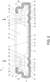
FIG. 2 is a cross-sectional view of the slide rail assembly according to the embodiment of the present invention. - As shown in
FIG. 1 andFIG. 2 , aslide rail assembly 20 comprises afirst rail 22, aslide assisting device 24 and asecond rail 26 according to an embodiment of the present invention. In the present embodiment, thefirst rail 22 is an outer rail, and thesecond rail 26 is an inner rail. - The
first rail 22 comprises afirst wall 28a, asecond wall 28b and afirst middle wall 30 connected between thefirst wall 28a and thesecond wall 28b. Apassage 32 is defined by thefirst wall 28a, thesecond wall 28b and thefirst middle wall 30. - The
slide assisting device 24 is arranged in thepassage 32 of thefirst rail 22. Theslide assisting device 24 comprises a first rollingmember 34. In the present embodiment, the firstrolling member 34 is a ball, but the present invention is not limited thereto. Preferably, theslide assisting device 24 further comprises aretainer 35 configured to mount the firstrolling member 34. - The
second rail 26 is movable relative to thefirst rail 22, and thesecond rail 26 comprises afirst side wall 36a, asecond side wall 36b and asecond middle wall 38 connected between thefirst side wall 36a and thesecond side wall 36b. - The
first middle wall 30 of thefirst rail 22 is formed with afirst ball groove 40, and thesecond rail 26 further comprises afirst extension wall 42. Thefirst extension wall 42 comprises afirst extension section 44, asecond extension section 46 and afirst middle section 48 connected between thefirst extension section 44 and thesecond extension section 46. Thefirst extension section 44 is extended from thefirst side wall 36a of thesecond rail 26. Oneend 46a of thesecond extension section 46 is extended toward thesecond middle wall 38 of thesecond rail 26. Thefirst middle section 48 is formed with asecond ball groove 50. The first rollingmember 34 is located between thefirst ball groove 40 and thesecond ball groove 50. - Preferably, the
first wall 28a of thefirst rail 22 comprises a first supporting section K1 and a second supporting section K2 bent relative to the first supporting section K1. The second supporting section K2 is configured to hold thefirst side wall 36a of thesecond rail 26, in order to prevent thesecond rail 26 from being detached from thepassage 32 of thefirst rail 22. - Preferably, the
first extension section 44 is reversely folded from thefirst side wall 36a of thesecond rail 26, and thefirst extension section 44 is configured to abut against thefirst side wall 36a of thesecond rail 26. Thefirst middle section 48 is adjacent to thefirst side wall 36a of thesecond rail 26. For example, a portion of thefirst middle section 48 is configured to abut against thefirst side wall 36a of thesecond rail 26. Theend 46a of thesecond extension section 46 is configured to abut against the secondmiddle wall 38 of thesecond rail 26. - Preferably, the second
middle wall 38 of thesecond rail 26 has a first end part E1, and the first end part E1 is extended toward the second supporting section K2 of thefirst rail 22 along a first direction D1 and beyond a center position C1 of the first rollingmember 34. - Preferably, the
first rail 22 further comprises afirst arc part 52 bent relative to the firstmiddle wall 30. Thefirst arc part 52 is formed with thefirst ball groove 40, and thesecond ball groove 50 of the firstmiddle section 48 of thesecond rail 26 has an arc contour. The first rollingmember 34 is in contact between thefirst ball groove 40 and the arc contour of thesecond ball groove 50 of the firstmiddle section 48. - Preferably, the first
middle wall 30 of thefirst rail 22 has a first surface S1 and a second surface S2 opposite to each other, and the first surface S1 faces toward thesecond rail 26. Thefirst arc part 52 comprises afirst shoulder section 43a, asecond shoulder section 43b and avalley section 45 located between thefirst shoulder section 43a and thesecond shoulder section 43b. Theshoulder sections middle wall 30, so as to enhance structural strength of the first rail 22 (the firstmiddle wall 30 of the first rail 22), and further improve stability of the first rollingmember 34 located between thefirst ball groove 40 and thesecond ball groove 50. - Preferably, the
slide assisting device 24 further comprises a second rollingmember 54. In the present embodiment, the second rollingmember 54 is a ball, but the present invention is not limited thereto. Preferably, theretainer 35 is configured to mount the second rollingmember 54. The firstmiddle wall 30 of thefirst rail 22 is further formed with athird ball groove 56, and thesecond rail 26 further comprises asecond extension wall 58. Thesecond extension wall 58 comprises athird extension section 60 , afourth extension section 62 and a secondmiddle section 64 connected between thethird extension section 60 and thefourth extension section 62. Thethird extension section 60 is extended from thesecond side wall 36b of thesecond rail 26. Oneend 62a of thefourth extension section 62 is extended toward the secondmiddle wall 38 of thesecond rail 26. The secondmiddle section 64 is formed with afourth ball groove 66. The second rollingmember 54 is located between thethird ball groove 56 and thefourth ball groove 66. - Preferably, the
second wall 28b of thefirst rail 22 comprises a third supporting section K3 and a fourth supporting section K4 bent relative to the third supporting section K3. The fourth supporting section K4 is configured to hold thesecond side wall 36b of thesecond rail 26, in order to prevent thesecond rail 26 from being detached from thepassage 32 of thefirst rail 22. The secondmiddle wall 38 of thesecond rail 26 has a second end part E2 opposite to the first end part E1, and the second end part E2 is extended toward the fourth supporting section K4 of thefirst rail 22 along a second direction D2 and beyond a center position C2 of the second rollingmember 54. The second direction D2 is opposite to the first direction D1. - Preferably, the
third extension section 60 is reversely folded from thesecond side wall 36b of thesecond rail 26, and thethird extension section 60 is configured to abut against thesecond side wall 36b of thesecond rail 26. The secondmiddle section 64 is adjacent to thesecond side wall 36b of thesecond rail 26. For example, a portion of the secondmiddle section 64 is configured to abut against thesecond side wall 36b of thesecond rail 26. Theend 62a of thefourth extension section 62 is configured to abut against the secondmiddle wall 38 of thesecond rail 26. - Preferably, the
first rail 22 further comprises asecond arc part 68 bent relative to the firstmiddle wall 30. Thesecond arc part 68 is formed with thethird ball groove 56, and thefourth ball groove 66 of the secondmiddle section 64 of thesecond rail 26 has an arc contour. The second rollingmember 54 is in contact between thethird ball groove 56 and the arc contour of thefourth ball groove 66 of the secondmiddle section 64. - Preferably, the
second arc part 68 comprises afirst shoulder section 53a, asecond shoulder section 53b and avalley section 55 located between thefirst shoulder section 53a and thesecond shoulder section 53b. Theshoulder sections middle wall 30, so as to enhance structural strength of the first rail 22 (the firstmiddle wall 30 of the first rail 22), and further improve stability of the second rollingmember 54 located between thethird ball groove 56 and thefourth ball groove 66. - Moreover, the
second rail 26 is configured to carry a carried object (not shown in figures), and the carried object is configured to apply forces F1, F2 to two sides of thesecond rail 26 due to gravity. When the first force F1 is applied to a position adjacent to the first end part E1 of the second middle wall 38 of the second rail 26, through extending the second extension section 46 toward the second middle wall 38 of the second rail 26 (such as abutting against the secondmiddle wall 38 of the second rail 26), entire structural strength or supporting strength of the second rail 26 (or the slide rail assembly 20) can be improved; furthermore, through extending the first end part E1 of the second middle wall 38 beyond the center position C1 of the first rolling member 34 along the first direction D1, the second middle wall 38 of the second rail 26 can be prevented from being deformed or damaged by the first force F1, such that the entire structural strength or supporting strength of the second rail 26 (or the slide rail assembly 20) can be further improved; furthermore, through reversely folding the first extension section 44 from the first side wall 36a of the second rail 26 with the first extension section 44 abutting against the first side wall 36a of the second rail 26, the entire structural strength or supporting strength of the second rail 26 (or the slide rail assembly 20) can be further improved; furthermore, through arranging the first arc part 52 of the first rail 22 to be bent relative to the first middle wall 30 for reinforcement, entire structural strength or supporting strength of the first rail 22 (or the slide rail assembly 20) can be improved; furthermore, through arranging the first shoulder section 43a and the second shoulder section 43b of the first arc part 52 to be protruded or raised relative to the first surface S1 of the first middle wall 30, the structural strength of the first rail 22 (the first middle wall 30 of the first rail 22) can be improved, so as to further improve stability of the first rolling member 34 located between the first ball groove 40 and the second ball groove 50. - Similarly, when the second force F2 is applied to a position adjacent to the second end part E2 of the second middle wall 38 of the second rail 26, through extending the fourth extension section 62 toward the second middle wall 38 of the second rail 26 (such as abutting against the second middle wall 38 of the second rail 26), the entire structural strength or supporting strength of the second rail 26 (or the slide rail assembly 20) can be improved; furthermore, through extending the second end part E2 of the second middle wall 38 beyond the center position C2 of the second rolling member 54 along the second direction D2, the second middle wall 38 of the second rail 26 can be prevented from being deformed or damaged by the second force F2, such that the entire structural strength or supporting strength of the second rail 26 (or the slide rail assembly 20) can be further improved; furthermore, through reversely folding the third extension section 60 from the second side wall 36b of the second rail 26 with the third extension section 44 60 abutting against the second side wall 36b of the second rail 26, the entire structural strength or supporting strength of the second rail 26 (or the slide rail assembly 20) can be further improved; furthermore, through arranging the second arc part 68 of the first rail 22 to be bent relative to the first middle wall 30 for reinforcement, the entire structural strength or supporting strength of the first rail 22 (or the slide rail assembly 20) can be improved; furthermore, through arranging the first shoulder section 53a and the second shoulder section 53b of the second arc part 68 to be protruded or raised relative to the first surface S1 of the first middle wall 30, the structural strength of the first rail 22 (the first middle wall 30 of the first rail 22) can be improved, so as to further improve stability of the second rolling member 54 located between the third ball groove 56 and the fourth ball groove 66.
- An embodiment of the present invention further provides a slide rail, such as a slide rail identical to the
second rail 26 having the aforementioned structural configuration. The technical features of the slide rail can refer to structural configuration of thesecond rail 26 shown inFIG. 2 and related descriptions. For simplification, no further illustration is provided. - Therefore, the
slide rail assembly 20 and the slide rail thereof (such as the second rail 26) provided by the embodiments of the present invention can have better structural strength or supporting strength through the aforementioned technical features.
Claims (12)
- A slide rail assembly (20), comprising:a first rail (22) comprising a first wall (28a), a second wall (28b) and a first middle wall (30) connected between the first wall (28a) and the second wall (28b), a passage (32) being defined by the first wall (28a), the second wall (28b) and the first middle wall (30);a slide assisting device (24) arranged in the passage (32) of the first rail (22), and the slide assisting device (24) comprising a first rolling member (34); anda second rail (26) movable relative to the first rail (22), the second rail (26) comprising a first side wall (36a), a second side wall (36b) and a second middle wall (38) connected between the first side wall (36a) and the second side wall (36b);characterized in that:wherein the first middle wall (30) of the first rail (22) is formed with a first ball groove (40), the second rail (26) further comprises a first extension wall (42), the first extension wall (42) comprises a first extension section (44), a second extension section (46) and a first middle section (48) connected between the first extension section (44) and the second extension section (46), the first extension section (44) is extended from the first side wall (36a) of the second rail (26), the second extension section (46) is extended toward the second middle wall (38) of the second rail (26), and the first middle section (48) is formed with a second ball groove (50) ;wherein the first rolling member (34) is located between the first ball groove (40) and the second ball groove (50).
- The slide rail assembly of claim 1, characterized in that the first wall (28a) of the first rail (22) comprises a first supporting section and a second supporting section bent relative to the first supporting section, and the second supporting section is configured to hold the first side wall (36a) of the second rail (26) .
- The slide rail assembly of claim 1 or 2, characterized in that the first extension section (44) is reversely folded from the first side wall (36a) of the second rail (26), and the second extension section (46) is configured to abut against the second middle wall (38) of the second rail (26).
- The slide rail assembly of claim 2, characterized in that the second middle wall (38) of the second rail (26) has a first end part, and the first end part is extended toward the second supporting section of the first rail (22) and beyond a center position of the first rolling member (34).
- The slide rail assembly of any of claims 1-4, characterized in that the first rail (22) further comprises a first arc part (52) bent relative to the first middle wall (30), the first arc part (52) is formed with the first ball groove (40), and the first middle section (48) of the second rail (26) has an arc contour.
- The slide rail assembly of any of claims 1-5, characterized in that the second wall (28b) of the first rail (22) comprises a third supporting section and a fourth supporting section bent relative to the third supporting section, and the fourth supporting section is configured to hold the second side wall (36b) of the second rail (26).
- The slide rail assembly of claim 6, characterized in that the slide assisting device (24) further comprises a second rolling member (54); wherein the first middle wall (30) of the first rail (22) is further formed with a third ball groove (56), the second rail (26) further comprises a second extension wall (58), the second extension wall (58) comprises a third extension section (60), a fourth extension section (62) and a second middle section (64) connected between the third extension section (60) and the fourth extension section (62), the third extension section (60) is extended from the second side wall (36b) of the second rail (26), the fourth extension section (62) is extended toward the second middle wall (38) of the second rail (26), and the second middle section (64) is formed with a fourth ball groove (66); wherein the second rolling member (54) is located between the third ball groove (56) and the fourth ball groove (66).
- The slide rail assembly of claim 7, characterized in that the second middle wall (38) of the second rail (26) has a second end part, and the second end part is extended toward the fourth supporting section of the first rail (22) and beyond a center position of the second rolling member (54).
- The slide rail assembly of claim 8, characterized in that the third extension section (60) is reversely folded from the second side wall (36b) of the second rail (26), and the fourth extension section (62) is configured to abut against the second middle wall (38) of the second rail (26).
- The slide rail assembly of claim 8 or 9, characterized in that the first rail (22) further comprises a second arc part (68) bent relative to the first middle wall (30), the second arc part (68) is formed with the third ball groove (56), and the second middle section (64) of the second rail (26) has an arc contour.
- A slide rail (26), comprising:a first side wall (36a);a second side wall (36b); anda middle wall (38) connected between the first side wall (36a) and the second side wall (36b);characterized in that:wherein the slide rail (26) further comprises a first extension wall (42), the first extension wall (42) comprises a first extension section (44), a second extension section (46) and a first middle section (48) connected between the first extension section (44) and the second extension section (46), the first extension section (44) is extended from the first side wall (36a), the second extension section (46) is extended toward the middle wall (38), and the first middle section (48) is formed with a ball groove (50);wherein the slide rail (26) further comprises a second extension wall (58), the second extension wall (58) comprises a third extension section (60), a fourth extension section (62) and a second middle section (64) connected between the third extension section (60) and the fourth extension section (62), the third extension section (60) is extended from the second side wall (36b), the fourth extension section (62) is extended toward the middle wall (38), and the second middle section (64) is formed with a ball groove (66).
- The slide rail of claim 11, characterized in that the first extension section (44) is reversely folded from the first side wall (36a), and the second extension section (46) is configured to abut against the middle wall (38); wherein the third extension section (60) is reversely folded from the second side wall (36b), and the fourth extension section (62) is configured to abut against the middle wall (38).
Applications Claiming Priority (1)
| Application Number | Priority Date | Filing Date | Title |
|---|---|---|---|
| TW112111852A TWI818879B (en) | 2023-03-27 | 2023-03-27 | Slide rail assembly and slide rail thereof |
Publications (2)
| Publication Number | Publication Date |
|---|---|
| EP4437907A1 true EP4437907A1 (en) | 2024-10-02 |
| EP4437907B1 EP4437907B1 (en) | 2025-07-23 |
Family
ID=89509145
Family Applications (1)
| Application Number | Title | Priority Date | Filing Date |
|---|---|---|---|
| EP24150512.2A Active EP4437907B1 (en) | 2023-03-27 | 2024-01-05 | Slide rail assembly and slide rail thereof |
Country Status (4)
| Country | Link |
|---|---|
| US (1) | US12408750B2 (en) |
| EP (1) | EP4437907B1 (en) |
| JP (1) | JP7679934B2 (en) |
| TW (1) | TWI818879B (en) |
Families Citing this family (1)
| Publication number | Priority date | Publication date | Assignee | Title |
|---|---|---|---|---|
| TWI847636B (en) * | 2023-03-27 | 2024-07-01 | 川湖科技股份有限公司 | Slide rail assembly and slide rail thereof |
Citations (3)
| Publication number | Priority date | Publication date | Assignee | Title |
|---|---|---|---|---|
| WO2008038472A1 (en) * | 2006-09-28 | 2008-04-03 | Thk Co., Ltd. | Slide rail unit |
| CN201721351U (en) * | 2010-07-22 | 2011-01-26 | 江苏裕华汽车零部件有限公司 | Slide rail for vehicle seat |
| US9894993B2 (en) | 2016-05-31 | 2018-02-20 | King Slide Works Co., Ltd. | Slide rail and slide rail assembly |
Family Cites Families (8)
| Publication number | Priority date | Publication date | Assignee | Title |
|---|---|---|---|---|
| US962502A (en) * | 1910-02-17 | 1910-06-28 | Axel Elmborg | Drawer-guide. |
| DE2942161A1 (en) * | 1979-10-18 | 1981-04-30 | Paul Hettich & Co, 4983 Kirchlengern | DRAWER GUIDE FOR A DRAWER |
| FR2544415B1 (en) | 1983-04-15 | 1986-09-05 | Peugeot Cycles | BALL SLIDE ELEMENT AND SLIDE THUS PRODUCED |
| US6378968B1 (en) * | 1999-06-07 | 2002-04-30 | Kuo-Chan Weng | Sliding track assembly |
| CN201076201Y (en) * | 2007-07-02 | 2008-06-25 | 川湖科技股份有限公司 | Hanging hole type slide rail |
| CN203828433U (en) * | 2014-04-21 | 2014-09-17 | 陈明伟 | Seven-ball three-section full-expansion concealed type steel ball drawer guide rail |
| TWI594712B (en) * | 2016-06-16 | 2017-08-11 | 川湖科技股份有限公司 | Supporting device for a rail |
| JP2018090119A (en) | 2016-12-05 | 2018-06-14 | トヨタ紡織株式会社 | Slide device for seat |
-
2023
- 2023-03-27 TW TW112111852A patent/TWI818879B/en active
- 2023-10-02 US US18/479,517 patent/US12408750B2/en active Active
-
2024
- 2024-01-05 JP JP2024000509A patent/JP7679934B2/en active Active
- 2024-01-05 EP EP24150512.2A patent/EP4437907B1/en active Active
Patent Citations (3)
| Publication number | Priority date | Publication date | Assignee | Title |
|---|---|---|---|---|
| WO2008038472A1 (en) * | 2006-09-28 | 2008-04-03 | Thk Co., Ltd. | Slide rail unit |
| CN201721351U (en) * | 2010-07-22 | 2011-01-26 | 江苏裕华汽车零部件有限公司 | Slide rail for vehicle seat |
| US9894993B2 (en) | 2016-05-31 | 2018-02-20 | King Slide Works Co., Ltd. | Slide rail and slide rail assembly |
Also Published As
| Publication number | Publication date |
|---|---|
| JP7679934B2 (en) | 2025-05-20 |
| TW202437963A (en) | 2024-10-01 |
| US12408750B2 (en) | 2025-09-09 |
| EP4437907B1 (en) | 2025-07-23 |
| TWI818879B (en) | 2023-10-11 |
| JP2024139684A (en) | 2024-10-09 |
| US20240324767A1 (en) | 2024-10-03 |
Similar Documents
| Publication | Publication Date | Title |
|---|---|---|
| US7837584B2 (en) | Chain | |
| CN101421060A (en) | Method for joining members to each other | |
| EP4437907B1 (en) | Slide rail assembly and slide rail thereof | |
| WO2009076691A3 (en) | Power assist element | |
| US4041790A (en) | Roller chain connecting link spring clip | |
| CN105051412A (en) | Chain | |
| WO2024249757A3 (en) | Directional tipped catheters | |
| KR101562824B1 (en) | Waterproof coupling structure for expansion joint device | |
| US20230167847A1 (en) | Mechanical system having high rotation flexure bearing | |
| EP4438400A1 (en) | Slide rail assembly and slide rail thereof | |
| EP3578726B1 (en) | Corrugated steel sheet having inclined portion in which position of coupling hole is adjusted and joint corrugated steel sheet structure using same | |
| WO2025187610A8 (en) | Terminal block | |
| US10549390B2 (en) | Body component having a tab element for pre-fastening | |
| US11892021B2 (en) | Connection structure | |
| CN118728850A (en) | Slide rail assembly and its slide rail | |
| JP3130519U (en) | Nested tube connection sleeve | |
| EP4454906A1 (en) | Method for manufacturing stabilizer, and stabilizer | |
| US20250146529A1 (en) | Retainer cage and bearing device | |
| EP3896296A1 (en) | Coupling device and all-terrain vehicle | |
| EP4454907A1 (en) | Stabilizer manufacturing method, stabilizer, and tubular member for manufacturing stabilizer | |
| JPH11280727A (en) | C-shaped ring | |
| WO2025005072A1 (en) | Pressing unit and spring member | |
| JP2005016235A (en) | Segment connection structure | |
| KR200421736Y1 (en) | Clamping band | |
| JPH04110266U (en) | hollow metal seal |
Legal Events
| Date | Code | Title | Description |
|---|---|---|---|
| PUAI | Public reference made under article 153(3) epc to a published international application that has entered the european phase |
Free format text: ORIGINAL CODE: 0009012 |
|
| STAA | Information on the status of an ep patent application or granted ep patent |
Free format text: STATUS: REQUEST FOR EXAMINATION WAS MADE |
|
| 17P | Request for examination filed |
Effective date: 20240826 |
|
| AK | Designated contracting states |
Kind code of ref document: A1 Designated state(s): AL AT BE BG CH CY CZ DE DK EE ES FI FR GB GR HR HU IE IS IT LI LT LU LV MC ME MK MT NL NO PL PT RO RS SE SI SK SM TR |
|
| GRAP | Despatch of communication of intention to grant a patent |
Free format text: ORIGINAL CODE: EPIDOSNIGR1 |
|
| STAA | Information on the status of an ep patent application or granted ep patent |
Free format text: STATUS: GRANT OF PATENT IS INTENDED |
|
| RIC1 | Information provided on ipc code assigned before grant |
Ipc: F16C 29/04 20060101ALI20250403BHEP Ipc: B60N 2/07 20060101ALI20250403BHEP Ipc: A47B 88/487 20170101AFI20250403BHEP |
|
| INTG | Intention to grant announced |
Effective date: 20250417 |
|
| GRAS | Grant fee paid |
Free format text: ORIGINAL CODE: EPIDOSNIGR3 |
|
| GRAA | (expected) grant |
Free format text: ORIGINAL CODE: 0009210 |
|
| STAA | Information on the status of an ep patent application or granted ep patent |
Free format text: STATUS: THE PATENT HAS BEEN GRANTED |
|
| AK | Designated contracting states |
Kind code of ref document: B1 Designated state(s): AL AT BE BG CH CY CZ DE DK EE ES FI FR GB GR HR HU IE IS IT LI LT LU LV MC ME MK MT NL NO PL PT RO RS SE SI SK SM TR |
|
| REG | Reference to a national code |
Ref country code: GB Ref legal event code: FG4D |
|
| REG | Reference to a national code |
Ref country code: CH Ref legal event code: EP |
|
| REG | Reference to a national code |
Ref country code: DE Ref legal event code: R096 Ref document number: 602024000308 Country of ref document: DE |
|
| REG | Reference to a national code |
Ref country code: IE Ref legal event code: FG4D |
|
| REG | Reference to a national code |
Ref country code: NL Ref legal event code: MP Effective date: 20250723 |
|
| PG25 | Lapsed in a contracting state [announced via postgrant information from national office to epo] |
Ref country code: PT Free format text: LAPSE BECAUSE OF FAILURE TO SUBMIT A TRANSLATION OF THE DESCRIPTION OR TO PAY THE FEE WITHIN THE PRESCRIBED TIME-LIMIT Effective date: 20251124 |
|
| PG25 | Lapsed in a contracting state [announced via postgrant information from national office to epo] |
Ref country code: NL Free format text: LAPSE BECAUSE OF FAILURE TO SUBMIT A TRANSLATION OF THE DESCRIPTION OR TO PAY THE FEE WITHIN THE PRESCRIBED TIME-LIMIT Effective date: 20250723 |
|
| REG | Reference to a national code |
Ref country code: AT Ref legal event code: MK05 Ref document number: 1815483 Country of ref document: AT Kind code of ref document: T Effective date: 20250723 |
|
| PG25 | Lapsed in a contracting state [announced via postgrant information from national office to epo] |
Ref country code: IS Free format text: LAPSE BECAUSE OF FAILURE TO SUBMIT A TRANSLATION OF THE DESCRIPTION OR TO PAY THE FEE WITHIN THE PRESCRIBED TIME-LIMIT Effective date: 20251123 |
|
| PG25 | Lapsed in a contracting state [announced via postgrant information from national office to epo] |
Ref country code: NO Free format text: LAPSE BECAUSE OF FAILURE TO SUBMIT A TRANSLATION OF THE DESCRIPTION OR TO PAY THE FEE WITHIN THE PRESCRIBED TIME-LIMIT Effective date: 20251023 |
|
| REG | Reference to a national code |
Ref country code: LT Ref legal event code: MG9D |
|
| PG25 | Lapsed in a contracting state [announced via postgrant information from national office to epo] |
Ref country code: AT Free format text: LAPSE BECAUSE OF FAILURE TO SUBMIT A TRANSLATION OF THE DESCRIPTION OR TO PAY THE FEE WITHIN THE PRESCRIBED TIME-LIMIT Effective date: 20250723 |
|
| PG25 | Lapsed in a contracting state [announced via postgrant information from national office to epo] |
Ref country code: FI Free format text: LAPSE BECAUSE OF FAILURE TO SUBMIT A TRANSLATION OF THE DESCRIPTION OR TO PAY THE FEE WITHIN THE PRESCRIBED TIME-LIMIT Effective date: 20250723 |
|
| PG25 | Lapsed in a contracting state [announced via postgrant information from national office to epo] |
Ref country code: HR Free format text: LAPSE BECAUSE OF FAILURE TO SUBMIT A TRANSLATION OF THE DESCRIPTION OR TO PAY THE FEE WITHIN THE PRESCRIBED TIME-LIMIT Effective date: 20250723 |
|
| PG25 | Lapsed in a contracting state [announced via postgrant information from national office to epo] |
Ref country code: GR Free format text: LAPSE BECAUSE OF FAILURE TO SUBMIT A TRANSLATION OF THE DESCRIPTION OR TO PAY THE FEE WITHIN THE PRESCRIBED TIME-LIMIT Effective date: 20251024 |
|
| PG25 | Lapsed in a contracting state [announced via postgrant information from national office to epo] |
Ref country code: SE Free format text: LAPSE BECAUSE OF FAILURE TO SUBMIT A TRANSLATION OF THE DESCRIPTION OR TO PAY THE FEE WITHIN THE PRESCRIBED TIME-LIMIT Effective date: 20250723 |
|
| PGFP | Annual fee paid to national office [announced via postgrant information from national office to epo] |
Ref country code: IE Payment date: 20251203 Year of fee payment: 3 |
|
| PG25 | Lapsed in a contracting state [announced via postgrant information from national office to epo] |
Ref country code: LV Free format text: LAPSE BECAUSE OF FAILURE TO SUBMIT A TRANSLATION OF THE DESCRIPTION OR TO PAY THE FEE WITHIN THE PRESCRIBED TIME-LIMIT Effective date: 20250723 |
|
| PG25 | Lapsed in a contracting state [announced via postgrant information from national office to epo] |
Ref country code: BG Free format text: LAPSE BECAUSE OF FAILURE TO SUBMIT A TRANSLATION OF THE DESCRIPTION OR TO PAY THE FEE WITHIN THE PRESCRIBED TIME-LIMIT Effective date: 20250723 Ref country code: PL Free format text: LAPSE BECAUSE OF FAILURE TO SUBMIT A TRANSLATION OF THE DESCRIPTION OR TO PAY THE FEE WITHIN THE PRESCRIBED TIME-LIMIT Effective date: 20250723 |
|
| PG25 | Lapsed in a contracting state [announced via postgrant information from national office to epo] |
Ref country code: RS Free format text: LAPSE BECAUSE OF FAILURE TO SUBMIT A TRANSLATION OF THE DESCRIPTION OR TO PAY THE FEE WITHIN THE PRESCRIBED TIME-LIMIT Effective date: 20251023 |
|
| PG25 | Lapsed in a contracting state [announced via postgrant information from national office to epo] |
Ref country code: ES Free format text: LAPSE BECAUSE OF FAILURE TO SUBMIT A TRANSLATION OF THE DESCRIPTION OR TO PAY THE FEE WITHIN THE PRESCRIBED TIME-LIMIT Effective date: 20250723 |
|
| PG25 | Lapsed in a contracting state [announced via postgrant information from national office to epo] |
Ref country code: SM Free format text: LAPSE BECAUSE OF FAILURE TO SUBMIT A TRANSLATION OF THE DESCRIPTION OR TO PAY THE FEE WITHIN THE PRESCRIBED TIME-LIMIT Effective date: 20250723 |
|
| PG25 | Lapsed in a contracting state [announced via postgrant information from national office to epo] |
Ref country code: DK Free format text: LAPSE BECAUSE OF FAILURE TO SUBMIT A TRANSLATION OF THE DESCRIPTION OR TO PAY THE FEE WITHIN THE PRESCRIBED TIME-LIMIT Effective date: 20250723 |
|
| PGFP | Annual fee paid to national office [announced via postgrant information from national office to epo] |
Ref country code: DE Payment date: 20251216 Year of fee payment: 3 |
|
| PG25 | Lapsed in a contracting state [announced via postgrant information from national office to epo] |
Ref country code: IT Free format text: LAPSE BECAUSE OF FAILURE TO SUBMIT A TRANSLATION OF THE DESCRIPTION OR TO PAY THE FEE WITHIN THE PRESCRIBED TIME-LIMIT Effective date: 20250723 |
|
| PG25 | Lapsed in a contracting state [announced via postgrant information from national office to epo] |
Ref country code: CZ Free format text: LAPSE BECAUSE OF FAILURE TO SUBMIT A TRANSLATION OF THE DESCRIPTION OR TO PAY THE FEE WITHIN THE PRESCRIBED TIME-LIMIT Effective date: 20250723 |
|
| PG25 | Lapsed in a contracting state [announced via postgrant information from national office to epo] |
Ref country code: SK Free format text: LAPSE BECAUSE OF FAILURE TO SUBMIT A TRANSLATION OF THE DESCRIPTION OR TO PAY THE FEE WITHIN THE PRESCRIBED TIME-LIMIT Effective date: 20250723 Ref country code: EE Free format text: LAPSE BECAUSE OF FAILURE TO SUBMIT A TRANSLATION OF THE DESCRIPTION OR TO PAY THE FEE WITHIN THE PRESCRIBED TIME-LIMIT Effective date: 20250723 |