EP4437835A1 - Handheld electric tool and single-handed saw - Google Patents
Handheld electric tool and single-handed saw Download PDFInfo
- Publication number
- EP4437835A1 EP4437835A1 EP23810913.6A EP23810913A EP4437835A1 EP 4437835 A1 EP4437835 A1 EP 4437835A1 EP 23810913 A EP23810913 A EP 23810913A EP 4437835 A1 EP4437835 A1 EP 4437835A1
- Authority
- EP
- European Patent Office
- Prior art keywords
- power tool
- handheld power
- connecting rod
- handle
- effective length
- Prior art date
- Legal status (The legal status is an assumption and is not a legal conclusion. Google has not performed a legal analysis and makes no representation as to the accuracy of the status listed.)
- Pending
Links
Images







Classifications
-
- A—HUMAN NECESSITIES
- A01—AGRICULTURE; FORESTRY; ANIMAL HUSBANDRY; HUNTING; TRAPPING; FISHING
- A01G—HORTICULTURE; CULTIVATION OF VEGETABLES, FLOWERS, RICE, FRUIT, VINES, HOPS OR SEAWEED; FORESTRY; WATERING
- A01G3/00—Cutting implements specially adapted for horticultural purposes; Delimbing standing trees
- A01G3/08—Other tools for pruning, branching or delimbing standing trees
- A01G3/085—Motor-driven saws for pruning or branching
-
- A—HUMAN NECESSITIES
- A01—AGRICULTURE; FORESTRY; ANIMAL HUSBANDRY; HUNTING; TRAPPING; FISHING
- A01G—HORTICULTURE; CULTIVATION OF VEGETABLES, FLOWERS, RICE, FRUIT, VINES, HOPS OR SEAWEED; FORESTRY; WATERING
- A01G3/00—Cutting implements specially adapted for horticultural purposes; Delimbing standing trees
- A01G3/08—Other tools for pruning, branching or delimbing standing trees
- A01G3/085—Motor-driven saws for pruning or branching
- A01G3/086—Chain saws
-
- A—HUMAN NECESSITIES
- A01—AGRICULTURE; FORESTRY; ANIMAL HUSBANDRY; HUNTING; TRAPPING; FISHING
- A01G—HORTICULTURE; CULTIVATION OF VEGETABLES, FLOWERS, RICE, FRUIT, VINES, HOPS OR SEAWEED; FORESTRY; WATERING
- A01G3/00—Cutting implements specially adapted for horticultural purposes; Delimbing standing trees
- A01G3/02—Secateurs; Flower or fruit shears
- A01G3/033—Secateurs; Flower or fruit shears having motor-driven blades
- A01G3/0335—Secateurs; Flower or fruit shears having motor-driven blades having elongated or extended handles
-
- A—HUMAN NECESSITIES
- A01—AGRICULTURE; FORESTRY; ANIMAL HUSBANDRY; HUNTING; TRAPPING; FISHING
- A01G—HORTICULTURE; CULTIVATION OF VEGETABLES, FLOWERS, RICE, FRUIT, VINES, HOPS OR SEAWEED; FORESTRY; WATERING
- A01G3/00—Cutting implements specially adapted for horticultural purposes; Delimbing standing trees
- A01G3/02—Secateurs; Flower or fruit shears
- A01G3/033—Secateurs; Flower or fruit shears having motor-driven blades
- A01G3/037—Secateurs; Flower or fruit shears having motor-driven blades the driving means being an electric motor
-
- B—PERFORMING OPERATIONS; TRANSPORTING
- B25—HAND TOOLS; PORTABLE POWER-DRIVEN TOOLS; MANIPULATORS
- B25F—COMBINATION OR MULTI-PURPOSE TOOLS NOT OTHERWISE PROVIDED FOR; DETAILS OR COMPONENTS OF PORTABLE POWER-DRIVEN TOOLS NOT PARTICULARLY RELATED TO THE OPERATIONS PERFORMED AND NOT OTHERWISE PROVIDED FOR
- B25F5/00—Details or components of portable power-driven tools not particularly related to the operations performed and not otherwise provided for
- B25F5/02—Construction of casings, bodies or handles
Definitions
- the present application relates to a power tool, for example, a handheld power tool and a one-handed saw.
- a chainsaw also known as a hedge trimmer, is often used for pruning branches or forest trees.
- the chainsaw is generally a portable small or medium-sized chainsaw.
- the portable small or medium-sized chainsaw has a relatively low cutting height and cannot satisfy a working condition in which an object to be cut is slightly higher.
- a pole saw can satisfy high-position cutting, but cannot satisfy the convenience, lightweight, and flexibility of the portable small or medium-sized chainsaw.
- other handheld power tools such as electric scissors, a mower, and a handheld circular saw, also face the preceding situation.
- the user expects the tools to be compact and lightweight while satisfying the requirements of different pruning heights.
- one-handed saws are common in the field of power tools.
- a one-handed saw is generally a sawing power tool that is operable by the user with just one hand.
- the one-handed saws may generally be divided into a one-handed chainsaw, a mini chainsaw, a one-handed reciprocating saw, a mini reciprocating saw, a one-handed electric circular saw, a mini electric circular saw, and the like.
- An object of the present application is to provide a chainsaw and a handheld power tool that are convenient, lightweight, flexible, and operable with one hand to satisfy the requirements of the user for the length of the handheld power tool in different working conditions.
- a handheld power tool includes a motor; a handle for a user to hold, where a first switch is disposed on the handle and configured to at least control the starting and stopping of the motor; and an output assembly configured to perform an output operation.
- An adjustment device including a telescopic rod assembly is further included, where the length of the adjustment device changes so that the handheld power tool has at least two working states, that is, a first working state and a second working state.
- the distance between the frontmost side of the handheld power tool and the rearmost side of the first switch is defined as the effective length of the handheld power tool; where when the handheld power tool is in the first working state, the handheld power tool has a first effective length T1; and when the handheld power tool is in the second working state, the handheld power tool has a second effective length T2; where the first effective length T1 is less than or equal to 1 m, and the second effective length T2 is greater than the first effective length T1.
- the difference between the second effective length T2 and the first effective length T1 is greater than or equal to 10 cm.
- the difference between the second effective length T2 and the first effective length T1 is greater than or equal to 20 cm.
- the handheld power tool further includes a third effective length T3, where the third effective length T3 is greater than the second effective length T2, and the difference between the third effective length T3 and the second effective length T2 is greater than or equal to 10 cm.
- the handheld power tool further includes a coupling portion configured to mount a battery pack, where the total weight of the handheld power tool to which the battery pack is mounted is less than or equal to 6 kg.
- the adjustment device is telescopic to a first state and a second state along the front and rear direction of the handheld power tool.
- an adjustment switch is further included, where at least part of the adjustment switch is disposed on the handle; a stop portion is disposed on the adjustment switch; and when the adjustment switch is in an unlocked state, the stop portion is located on a movement path of the first switch controlling the starting and stopping of the motor, and at this time, the first switch is restricted from implementing a function of starting the motor.
- the adjustment device is provided with a locking hole
- the adjustment switch further includes a button for the user to operate, a first seesaw rotatably connected to the handle, and a reset torsion spring connected to the first seesaw, the button is capable of pressing one end of the first seesaw, and the other end of the first seesaw is selectively inserted into the locking hole.
- the adjustment device includes a first connecting rod connected to the handle and provided with the locking hole.
- the handheld power tool further includes a body housing, where the motor is disposed in the body housing, the output assembly is at least partially disposed in the body housing, and the adjustment device further includes a second connecting rod connected to the body housing.
- a locking assembly is disposed between the first connecting rod and the second connecting rod, and when both the first connecting rod and the second connecting rod extend out of the handle, the locking assembly locks the first connecting rod and the second connecting rod.
- the handheld power tool further includes a coupling portion configured to mount a battery pack, where the handheld power tool further includes a spring wire, the spring wire is inserted through the handle and the adjustment device, one end of the spring wire is electrically connected to the motor, and the other end of the spring wire is electrically connected to the battery pack.
- the handheld power tool further includes a power supply device for supplying electric power to at least the motor, where the power supply device is detachably connected to a rear part of the handle.
- the first effective length T1 is less than or equal to 60 cm.
- the first effective length T1 is less than or equal to 50 cm.
- the adjustment device is at least partially disposed between the output assembly and the handle.
- the handheld power tool is a chainsaw, electric scissors, a nail gun, or a reciprocating saw.
- a handheld power tool includes a motor accommodated in a body housing; a handle for a user to hold; and an output assembly configured to perform an output operation.
- the maximum distance of the handheld power tool along the direction parallel to the horizontal plane is defined as the total length of the handheld power tool, and the total length is adjustable.
- the handheld power tool has at least two working states, that is, a first working state and a second working state; where when the handheld power tool is in the first working state, the handheld power tool has a first total length M1; and when the handheld power tool is in the second working state, the handheld power tool has a second total length M2; where the second total length M2 is greater than the first total length M1, and the first total length M1 is less than 1.2 m.
- the handheld power tool includes only a first switch for controlling the starting and stopping of the motor, where the first switch is capable of controlling the starting and stopping of the motor when the handheld power tool is in different working states.
- a one-handed saw includes a motor accommodated in a body housing; a handle for a user to hold; and an output assembly configured to perform an output operation.
- the maximum distance of the one-handed saw along the direction parallel to the horizontal plane is defined as the total length of the one-handed saw, and the total length is adjustable.
- orientations or position relations indicated by terms such as “center”, “upper”, “lower”, “left”, “right”, “front”, and “rear” are based on the drawings. These orientations or position relations are intended only to facilitate and simplify the description of the present application and not to indicate or imply that a device or element referred to must have such particular orientations or must be configured or operated in such particular orientations. Thus, these orientations or position relations are not to be construed as limiting the present application.
- terms such as “first” and “second” are used merely for the purpose of description or are used for distinguishing between different structures or components, and are not to be construed as indicating or implying relative importance.
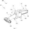
- FIG. 1 shows a handheld power tool 10 as a first example.
- the handheld power tool 10 is, for example, a chainsaw 100 generally configured to prune branches or forest trees.
- the chainsaw 100 generally includes a body housing 11, an output assembly 13, a motor 14, a power supply device, and the like.
- the body housing 11 has a front part 111, a rear part 112, and an intermediate part 113 between the front part 111 and the rear part 112.
- the output assembly 13 is a cutting assembly and includes a chain 132, a guide plate 131 that supports the movement of the chain 132, and a protective cover 133 that protects the chain.
- the motor 14 is disposed in the intermediate part 113 of the body housing 11 and configured to drive the chain 1132 to move around the guide plate 131 to implement the cutting operation.
- the body housing 11 is formed by a left housing 114 and a right housing 115.
- the right housing 115 is configured to accommodate the motor 14, and the axial direction of the motor 14 is basically perpendicular to the plane where the guide plate 131 is located.
- the output assemblies 13 of other forms of handheld power tools 10 than the chainsaw 100 may be different from the output assembly 13 of the chainsaw 100.
- the body housing 11 is further formed with a handle 12 for the user to hold.
- the handle 12 is disposed on the rear side of the body housing 11.
- a first switch 121 is disposed at one end of the handle 12 facing the rear part 112 of the body housing 11, and a coupling portion 122 for connecting a power supply device 17 is formed at one end of the handle 12 facing away from the rear part 112 of the body housing 11.
- the first switch 121 is operable by the user and is configured to control the starting and stopping of the motor 14.
- the first switch 121 may be configured to adjust the rotational speed of the motor 14.
- the first motor 121 is a trigger.
- the first switch 121 may be a switch that is pushable forward and backward or a switch that is togglable left and right.
- the power supply device 17 is connected to the coupling portion 122 and configured to supply electrical energy to the chainsaw 100.
- the power supply device is configured to be a battery pack. It is to be understood that the power supply device is not limited to the scenario of using the battery pack, and the power may be supplied to the circuit elements through mains power or an alternating current (AC) power supply in conjunction with the corresponding rectifier circuit, filter circuit, and voltage regulator circuit.
- AC alternating current
- the handle 12 includes a left handle housing 124 and a right handle housing 125.
- the left handle housing 124 and the right handle housing 125 form an accommodation space 123.
- the first switch 121 is connected to an integrated switch 1211 and configured to control the rotational speed of the motor 14 to control the cutting speed of the chainsaw 100.
- the integrated switch 1211 is disposed in the accommodation space 123 and corresponds to the first switch 121.
- the accommodation space 123 further accommodates a circuit board assembly 1221 that corresponds to the coupling portion 122 and is configured to control the power supply state of the power supply device 17 or communicate with the power supply device 17.
- the handle 12 is formed with or connected to an adjustment device 15.
- the adjustment device 15 extends along the direction of a first straight line 101 and is connected to the rear part 112 of the body housing 11.
- the adjustment device 15 has a first state and a second state in the direction of the first straight line 101.
- FIG. 1 shows a schematic view of the adjustment device 15 in the chainsaw 100 in the first state
- FIG. 3 shows a schematic view of the adjustment device 15 in the chainsaw 100 in the second state.
- the adjustment device 15 when the adjustment device 15 is in the first state, at least part of a front end surface 12a of the handle 12 abuts against the rear part 112.
- the adjustment device 15 when the adjustment device 15 is in the first state, the front end surface 12a of the handle 12 does not abut against the rear part 112, but is separated by a relatively short distance.
- the adjustment device 15 when the adjustment device 15 is in the second state, at least part of the adjustment device 15 is located between the rear part 112 of the body housing 11 and the front end surface 12a of the handle 12. It is to be understood that when the adjustment device 15 is in the first state, the adjustment device 15 can be completely disposed in the accommodation space 123 formed by the handle 12. When the adjustment device 15 is in the second state, at least part of the adjustment device 15 is located outside the accommodation space 123 formed by the handle 12.
- the adjustment device 15 is disposed between the body housing 11 and the handle 12.
- the handle 12 is movable relative to the rear part 112 along the extension direction of the adjustment device 15.
- the first distance L between the front end surface 12a of the handle 12 and the rear part 112 in the front and rear direction is greater than or equal to 0 and less than 1 meter.
- the first distance L between the front end surface 12a of the handle 12 and the rear part 112 in the front and rear direction is greater than or equal to 0 and less than 0.8 meters.
- the first distance L between the front end surface 12a of the handle 12 and the rear part 112 in the front and rear direction is greater than or equal to 0 and less than 0.6 meters.
- the first distance L may be understood as the maximum length of the part of the adjustment device 15 located between the handle 12 and the body housing 11. That is to say, during the movement of the handle 12, the maximum distance between the front end surface 12a of the handle 12 and the rear part 112 of the body housing 11 in the front and rear direction is greater than or equal to 0 and less than 1 meter.
- the adjustment device 15 includes at least a first connecting rod 151, a second connecting rod 152, and at least one intermediate connecting rod 153.
- the first connecting rod 151 is fixedly connected to the handle 12
- the second connecting rod 152 is fixedly connected to the rear part 121 of the body housing 11, and the intermediate connecting rod 153 is disposed between the first connecting rod 151 and the second connecting rod 152.
- first fixing pins 151a are formed on or connected to the first connecting rod 151
- multiple first through holes 12a are formed inside the handle 12
- two ends of the first fixing pin 151a are disposed in the first through hole 12a separately, thereby ensuring that the first connecting rod 151 is fixedly connected to the handle 12.
- second fixing pins 152a are formed on or connected to the second connecting rod 152, multiple second through holes 11a are formed on the rear part 112 of the body housing 11, and two ends of the second fixing pin 152a are disposed in the second through hole 11a separately, thereby ensuring that the second connecting rod 152 can be fixedly connected to the body housing 11.
- first connecting rod 151 is fixed to the handle 12 and the second connecting rod 152 is fixed to the rear part 121 of the body housing 11 exist, which are not limited here.
- those skilled in the art may provide a non-fixed connection method, for example, the first connecting rod can be slidably connected to the handle, or other examples, which are not limited here.
- the adjustment device 15 when the adjustment device 15 is in the first state, the adjustment device 15 can be completely disposed in the accommodation space 123 formed by the handle 12.
- the intermediate connecting rod 153 is sleeved on the second connecting rod 152, and the first connecting rod 151 is sleeved on the intermediate connecting rod 153.
- one intermediate connecting rod 153 may be provided.
- multiple intermediate connecting rods 153 may be provided. When multiple intermediate connecting rods are provided, the multiple intermediate connecting rods are sleeved together.
- the adjustment device 15 further includes multiple locking members.
- the second connecting rod 152 and each intermediate connecting rod 153 are provided with the locking members.
- the intermediate connecting rod 153 close to the first connecting rod 151 is used as an example for the detailed description of the working principle and function of the locking member.
- a first limiting member 1531 is formed on or connected to the intermediate connecting rod 152.
- the first limiting member 1531 has a first state and a second state in the direction of a second straight line 102.
- a first limiting portion is formed on the first connecting rod 151.
- the first limiting portion is optionally configured to be a first limiting hole 151b.
- the first limiting member 1531 on the intermediate connecting rod 154 is in the second state. At this time, the first limiting member 1531 is disposed in the first limiting hole 151b, and the first connecting rod 151 and the intermediate connecting rod are relatively fixed.
- the adjustment device 15 when the adjustment device 15 is in the second state, the adjustment device 15 has at least a first length and a second length in the direction of the first straight line 101.
- the first length is less than the second length.
- a second locking member 1521 is disposed at a limiting portion of the intermediate connecting rod 153, and the intermediate connecting rod 153 and the second connecting rod 152 are fixedly connected through the second locking member 1521.
- a first locking member 1531 is disposed at a limiting portion of the first connecting rod 151, and the first connecting rod 151 and the intermediate connecting rod 153 are fixedly connected through the first locking member 1521.
- the second connecting rod 152 and the intermediate connecting rod 153 close to the second connecting rod 152 are relatively fixed under the action of the locking member.
- FIG. 7B when the adjustment device 15 has the second length in the direction of the first straight line 101, all the locking members in the adjustment device 15 are located in the corresponding limiting holes.
- the first distance L between the grip center A of the handle 12 and the center B of the guide plate 131 is configured to be less than or equal to 1 meter.
- the chainsaw 100 further includes an adjustment switch 17 partially disposed in a groove 1241 formed by the left handle housing 124.
- the adjustment switch 17 is disposed on the handle 12.
- the adjustment switch 17 has a locking state and an unlocking state.
- the handle 12 is movable relative to the rear part 112 of the body housing 11 along the direction of the first straight line 101.
- the adjustment switch 17 includes a push rod 171 for the user to operate. When the user presses the push rod 171, the adjustment switch 17 is in the unlocking state; and when the user releases the push rod 171, the adjustment switch 17 is in the locking state.
- the adjustment switch 17 further includes a return spring 172. When the user releases the push rod 171, the adjustment switch 171 returns to the locking state from the unlocking state under the action of the return spring 172.
- the adjustment device 15 is provided with multiple locking holes 1532.
- a locking post 173 of the adjustment switch 17 is located in one of the multiple locking holes 1532 so that the handle 12 and the body housing 11 cannot move relative to each other.
- the locking post 173 of the adjustment switch 17 is disengaged from the locking hole 1532 so that the handle 12 and the body housing 11 are movable relatively in the direction of the first straight line 101. It is to be understood that many methods for implementing the adjustment switch exist.
- the handheld power tool 10 is, for example, electric scissors 10 generally configured to prune branches or forest trees.
- the electric scissors come in many shapes and types.
- the electric scissors 10 in this example include a body housing 1 and a motor (not shown in the figure) mounted in the body housing 1.
- the cutter part of a pruner 10 is formed by a fixed blade 3 and a movable blade 4.
- the fixed blade 3 is fixedly mounted relative to the housing 1, and the movable blade 4 is connected to the motor through a power transmission device.
- a knife edge 5 is formed between the fixed blade 3 and the movable blade 4.
- a switch 6 is mounted on the body housing 1.
- the pruner 10 is powered by the battery pack mounted at the end of the handle 12.
- the pruner 10 further includes a handle 7 for the user to hold and an adjustment device 8.
- the adjustment device is disposed between the body housing 1 and the handle 7.
- the handle 7 is movable relative to the body housing 1 along the extension direction of the adjustment device 8.
- the adjustment device 8 is telescopic to a first state and a second state along the extension direction of the adjustment device 8.
- FIG. 9A shows a schematic view of the electric scissors 10 when the adjustment device 8 is in the first state.
- FIG. 9B shows a schematic view of the electric scissors 10 when the adjustment device 8 is in the second state.
- the adjustment device 8 is in the first state, the distance between a front end surface 7a of the handle 7 and the rear part of the body housing 1 is the shortest.
- the part of the adjustment device located between the front end surface of the handle and the rear part of the body housing has at least a first length and a second length, and the second length is greater than the first length.
- the shortest distance between the front end surface 7a of the handle 7 and the rear end surface of the body housing 1 in the front and rear direction is greater than or equal to 0 and less than or equal to 0.03 meters.
- the shortest distance between the front end surface 7a of the handle 7 and the rear end surface of the body housing 1 in the front and rear direction is greater than or equal to 0 and less than or equal to 0.02 meters.
- the shortest distance between the front end surface 7a of the handle 7 and the rear end surface of the body housing 1 in the front and rear direction is greater than or equal to 0 and less than or equal to 0.01 meters.
- the handle 7 is formed with an accommodation space, and when the adjustment device 8 is in the first state, the adjustment device 8 can be completely disposed in the preceding accommodation space.
- the handheld power tool 10 is, for example, a chainsaw 100.
- the chainsaw 100 includes a first connecting rod 151 and a second connecting rod 152.
- the first connecting rod 151 is connected to a handle 12, and the second connecting rod 152 is connected to the rear part of a body housing 11.
- both the first connecting rod 151 and the second connecting rod 152 are aluminum tubes.
- the adjustment device 15 has a first state and a second state so that the chainsaw 100 has a retracted state and an extended state.
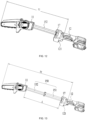
- the chainsaw 100 is in the retracted state.
- both the first connecting rod 151 and the second connecting rod 152 are retracted into the handle 12.
- the chainsaw 100 is in the extended state.
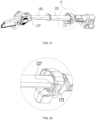
- the extended state is divided into two cases. In one case, as shown in FIGS. 11 and 12 , the second connecting rod 152 extends out of the handle 12, and the first connecting rod 151 is located inside the handle 12. In the other case, as shown in FIG. 13 , the first connecting rod 151 extends out of the handle 12, and the second connecting rod 152 extends out of the first connecting rod 151.
- the adjustment switch 17 lock the first connecting rod 151 and the second connecting rod 152, but also the adjustment switch 17 and the first switch 121 can be interlocked.
- the adjustment switch 17 includes a button 173 for the user to operate.
- the adjustment switch 17 When the user presses the button 173 to the right side of the chainsaw 100, the adjustment switch 17 is in the unlocking state; and when the user releases the button 173, the adjustment switch 17 is in the locking state.
- the adjustment switch 17 further includes a first seesaw 174 and a reset torsion spring 175.
- the first seesaw 174 rotates about a first rotary shaft, and the reset torsion spring 175 is sleeved on the first rotary shaft.
- the button 173 presses one end of the first seesaw 174 to lift the other end of the first seesaw 174; and when the user releases the button 173, under the action of the reset torsion spring 175, the button 173 and the first seesaw 174 are reset.
- the adjustment device 15 is provided with a locking hole 1532, and the end of the first seesaw 174 can extend into the locking hole 1532 so that the adjustment device 15 is locked, and the handle 12 and the body housing 11 cannot move relative to each other.
- the first connecting rod 151 and the second connecting rod 152 are both provided with locking holes 1532, and when the chainsaw 100 is in a fully retracted state, one locking hole 1532 on the first connecting rod 151 is aligned with one locking hole 1532 on the second connecting rod 152 so that the first seesaw 174 can lock the first connecting rod 151 and the second connecting rod 152 at the same time.
- a stop portion 1731 is disposed on the button 173.
- the stop portion 1731 is located on the movement path of the first switch 121 so that the first switch 121 cannot be pressed, and thus the first switch 121 is restricted from implementing a power-on function.
- the stop portion 1731 is located on a side of the button 173 facing the first switch 121, and the first seesaw 174 is located on a side of the button 173 facing away from the first switch 121. Since when the adjustment switch 17 is in the unlocking state, the handle 12 is movable relative to the body housing 11 along the direction of the first straight line, to ensure safety, the power-on function of the first switch 121 is limited.
- the adjustment switch 17 when the adjustment switch 17 is in the locking state, the end of the first seesaw 174 extends out of the locking hole 1532, the relative positions of the handle 12 and the body housing 11 are fixed, and the first switch 121 can implement the power-on function.
- the first switch 121 is locked by the adjustment switch 17 so that the first switch 121 cannot be pressed, and thus the first switch 121 cannot implement the power-on function.
- the wire is inserted through the handle 12 and the adjustment device 15, and the wire connects the motor 14 to the power supply device.
- the wire is a spring wire so that the wire can be lengthened and shortened as the adjustment device 15 is lengthened and shortened, and thus the power supply stability is not affected.
- a locking assembly is disposed between the first connecting rod 151 and the second connecting rod 152.
- the first connecting rod 151 and the second connecting rod 152 are locked by the locking assembly.
- the locking assembly provides resistance in the extension direction for the first connecting rod 151.
- the locking assembly includes a second seesaw 192 and a protective plate 191 disposed on the second connecting rod 152.
- the second seesaw 192 and the protective plate 191 are rotatably connected through a second rotary shaft.
- a resistance spring 193 is disposed on the protective plate 191 and sandwiched between the protective plate 191 and one end of the second seesaw 192.
- the first connecting rod 151 is provided with a limiting hole 1511, and one end of the second seesaw 192 facing away from the resistance spring can extend into the limiting hole 1511 so that the first connecting rod 151 and the second connecting rod 152 are locked.
- a limiting block 126 is disposed on the inner wall of the handle 12.
- the limiting block 126 can abut against the second seesaw 192 and compress the resistance spring 193.
- the limiting block 126 abuts against one end of the second seesaw 192 and compresses the resistance spring 193 so that the resistance spring 193 provides resistance to prevent the first connecting rod 151 from sliding out of the handle 12.
- the user needs to pull out the first connecting rod 151, the user needs to overcome the resistance of the resistance spring 193.
- the advantage of this setting is that the operating feel of the user is improved. When the user feels resistance when pulling out the second connecting rod 152, it can be considered that the second connecting rod 152 has been pulled out in place.
- the protective plate 191 covers two sides of the second seesaw 192 to prevent the following: branches and the like are accidentally in contact with the second seesaw 192, causing the resistance spring 193 to be pressed down due to the accidental contact when the resistance spring 193 does not need to be compressed, resulting in safety hazards.
- the protective plate 191 and the second connecting rod 152 are engaged through an elastic snap 194. During retraction, after the limiting block 126 abuts against the second seesaw 192, the protective plate 191 is fixed, the second connecting rod 152 continues retracting, and the external force applied by the user to the second connecting rod 152 overcomes the elastic force of the elastic snap 194.
- a clamping structure is further disposed between the handle 12 and the body housing 11.
- the clamping structure includes a clamping tooth 127 on the button 173 and a snap groove at the rear end of the body housing 11.
- the body housing 11 is provided with a protrusion 117, and the snap groove is opened on the protrusion 117.
- the clamping tooth 127 is disengaged from the snap groove, and the body housing 11 can slide relative to the handle 12; and when both the first connecting rod 151 and the second connecting rod 152 retract and the user releases the button 173, the clamping tooth 127 and the snap groove are clamped so that the body housing 11 and the handle 12 are locked.
- the user presses the button 173, and the button 173 presses one end of the first seesaw 174 to disengage the other end of the first seesaw 174 from the locking holes 1532.
- the handle 12 and the body housing 11 are movable along the direction of the first straight line 101.
- the second connecting rod 152 extends out of the handle 12, and the first connecting rod 151 is located inside the handle 12.
- the button 173 presses one end of the first seesaw 174 to disengage the other end of the first seesaw 174 from the locking hole 1532 of the second connecting rod 152.
- the handle 12 and the body housing 11 are movable along the direction of the first straight line 101.
- the user needs to apply a force to the second connecting rod 152 and the first connecting rod 151 along the length direction of the second connecting rod 152 so that the second seesaw 192 is disengaged from the limiting block 126, and the first connecting rod 151 is pulled out.
- one end of the second seesaw 192 facing away from the resistance spring extends into the limiting hole 1511 so that the first connecting rod 151 and the second connecting rod 152 are locked stably.
- the chainsaw 100 When the first connecting rod 151 extends out of the handle 12, the chainsaw 100 is in a fully extended state. If the user releases the button 173, under the action of the reset torsion spring 175, the button 173 and the first seesaw 174 are reset, and the end of the first seesaw 174 extends into the locking hole 1532 of the first connecting rod 151 to lock the first connecting rod 151.
- the user presses the button 173, and the button 173 presses one end of the first seesaw 174 to disengage the other end of the first seesaw 174 from the locking hole 1532 of the first connecting rod 151. Since one end of the second seesaw 192 is still located in the limiting hole 1511, the first connecting rod 151 and the second connecting rod 152 are locked. The first connecting rod 151 retracts into the handle 12 first, and when the limiting block 126 is in contact with the second seesaw 192, the limiting block 126 abuts against one end of the second seesaw 192 to disengage the other end of the second seesaw 192 from the limiting hole 1511.
- the second connecting rod 152 is slidable relative to the first connecting rod 151, and the second connecting rod 152 retracts into the first connecting rod 151.
- the user releases the button 173.
- the button 173 and the first seesaw 174 are reset, the end of the first seesaw 174 extends into the locking hole 1532 of the second connecting rod 152, and at the same time, the clamping tooth 127 and the snap groove are engaged.
- the handheld power tool 10 includes the output assembly 13 connected to the body housing and configured to perform an output operation; the adjustment device is disposed between the body housing and the handle; the handle is movable relative to the body housing along the extension direction of the adjustment device; and the distance between the frontmost side of the power tool and the rearmost side of the first switch 121 is defined as the effective length of the power tool, the handheld power tool 10 includes at least a first effective length T1 and a second effective length T2, and the handheld power tool 10 can work normally at both the first effective length T1 and the second effective length T2. That is to say, the handheld power tool 10 has at least a first working state and a second working state.
- the handheld power tool 10 When the handheld power tool 10 is in the first working state, the handheld power tool 10 has the first effective length T1; and when the handheld power tool 10 is in the second working state, the handheld power tool 10 has the second effective length T2.
- the first effective length T1 is less than or equal to 60 cm, and the second effective length T2 is greater than the first effective length T1.
- the effective length of the chainsaw refers to the distance between the frontmost side of the chain 132 and the rearmost side of the first switch 121. If the switch is the first switch 121 shown in the figure, the rearmost side of the switch is the rearmost side of the first switch 121. If the switch is a switch that is pushable forward and backward, the "rearmost side of the switch" in the effective length refers to the rearmost side of the switch when the switch is in the rearmost gear. That is to say, if the first switch 121 is a switch that is pushable forward and backward, the change in the position of the first switch 121 in the front and rear direction due to the turn-on of the switch is not included in the change in effective length.
- the effective length refers to the frontmost housing of the power tool without the saw blade attachment and the rearmost side of the first switch 121.
- the effective length refers to the chain and the rearmost side of the first switch 121.
- the distance between the frontmost side of the chain 132 and the rearmost side of the first switch 121 is T2, and T2 is about between 50 cm and 70 cm. In this example, T2 is about 65 cm. Both the first connecting rod 151 and the second connecting rod 152 can completely enter the handle 12 when retracted, thereby not only ensuring the portability of the chainsaw 100 but also ensuring the retractability of the chainsaw 100. In some examples, T2 may be 58 cm, 60 cm, 62 cm, 68 cm, or the like.
- T1 is greater than or equal to 25 cm and less than or equal to 50 cm.
- the power tool is moderately long and telescopic, so the power tool can adapt to a variety of working conditions.
- the difference between the second effective length T2 and the first effective length T1 is greater than or equal to 5 cm. In an example, the difference between the second effective length T2 and the first effective length T1 is greater than or equal to 10 cm. In an example, the difference between the second effective length T2 and the first effective length T1 is greater than or equal to 15 cm. In an example, the difference between the second effective length T2 and the first effective length T1 is greater than or equal to 20 cm.
- the power tool further includes the greatest third effective length T3, and the difference between the third effective length T3 and the second effective length T2 is greater than or equal to 10 cm.
- the power tool further includes the coupling portion 122 configured to mount a battery pack, and the total weight of the power tool to which the battery pack is mounted is less than or equal to 6 kg.
- the whole machine is relatively light in weight, is portable in operation, and can adapt to a wide range of applications.
- the total weight may be 5 kg or 4 kg.
- the total weight is about 2.2 kg.
- a nail gun a trimming machine, a one-handed reciprocating saw, a blower, a pruner, a hedge trimmer, a mower, a one-handed circular saw, a cleaning brush, and the like.
- the power tools are telescopic and can adapt to a variety of work conditions and workspaces.
- the adjustment device 15, the adjustment switch 17, the locking assembly, and the clamping structure provided in the third example above can be used in other handheld power tools 10, such as the nail gun shown in FIG. 23 and the reciprocating saw shown in FIG. 24 .
- FIG. 24 shows a one-handed mini reciprocating saw, which is also a small-sized reciprocating saw.
- the adjustment switch 17 is disposed on the handle 12. It is to be noted that when the solution disclosed in example three is applied in the form of an extension rod attachment, the handle 12 of the extension rod attachment is further provided with the additional adjustment switch 17 that is different from the switch provided on the original power tool.
- the adjustment switch 17 is electrically connected to the body housing of the handheld power tool 10.
- the chainsaw 100 further includes a housing disposed on a side of the handle 12 and connected to the handle 12, one end of the adjustment device 15 is located in the housing, and the other end of the adjustment device 15 is connected to the body housing 11.
- the adjustment device 15 includes at least the first connecting rod 151, the second connecting rod 152, and at least one intermediate connecting rod 153.
- the first connecting rod 151 is connected to the housing
- the second connecting rod 152 is connected to the body housing 11
- the intermediate connecting rod 153 is disposed between the first connecting rod 151 and the second connecting rod 152.
- connection manner of the first connecting rod 151, the second connecting rod 152, and the intermediate connecting rod 153 reference may be made to example one and example three, and the details are not repeated here.
- a spring wire 18 is inserted through the housing and the adjustment device 15. One end of the spring wire 18 is connected to the motor, and the other end of the spring wire is connected to the power supply device.
- T1 is greater than or equal to 10 cm and less than or equal to 40 cm.
- the length of the handheld power tool 10 from the grip part of the hand of the user to the frontmost side of the output assembly 13 for operation is smaller, that is to say, the volume of the tool is smaller. Therefore, when the solutions involved in the present application are adopted, the handheld power tool 10 is more compact and convenient, can be freely telescopic, and can satisfy the requirements of various working conditions.
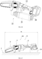
- the body housing 11 has a protruding support housing 116 so that the chain 132 will not touch the horizontal plane P when the chainsaw 100 is placed on the horizontal plane.
- the battery pack 130 may touch the horizontal plane P.
- the handheld power tool 10 has at least two working states, that is, the first working state and the second working state.
- the handheld power tool 10 When the handheld power tool 10 is in the first working state, the handheld power tool 10 has a first total length M1; and when the handheld power tool 10 is in the second working state, the handheld power tool has a second total length M2.
- the first total length M1 is less than or equal to 1.2 m, and the second total length M2 is greater than the first total length M1.
- the first total length M1 is less than or equal to 1 m.
- the first total length M1 is less than or equal to 0.8 m.
- the first total length M1 is less than or equal to 0.7 m.
- the first total length M1 is less than or equal to 0.6 m.
- the first total length M1 is less than or equal to 1 m, and the first effective length T1 is less than or equal to 60 cm. In an example, the first total length M1 is less than or equal to 1 m, and the first effective length T1 is less than or equal to 50 cm. In an example, the difference between the second total length M2 and the first total length M1 is greater than or equal to 10 cm. In an example, the difference between the second total length M2 and the first total length M1 is greater than or equal to 20 cm.
- the minimum value of the total length M refers to the shortest total length when the adjustment device 15 of the handheld power tool 10 or chainsaw 100 retracts along the front and rear direction of the tool.
- the content in the example shown in FIG. 27 that is repeated in the examples shown in FIGS. 1 to 26 is not repeatedly described.
- the first switch 121 can at least control the starting and stopping of the motor. That is to say, the first switch 121 may have other functions, such as adjusting the rotational speed of the motor. At least one first switch 121 may be provided.
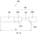
- a handheld power tool 10a includes an output assembly 13a and a handle 12a for the user to hold.
- the handheld power tool 10a has at least two switches that can control the starting and stopping of the motor, that is, a second switch 1212 and a first switch 1213.
- the second switch 1212 and the first switch 1213 are spaced apart from each other on the handle 12a.
- the handle 12a may be divided into a first handle portion 1201 and a second handle portion 1202.
- the first handle portion 1201 is closer to the output assembly 13a than the second handle portion 1202.
- the second switch 1212 is disposed on the first handle portion 1201, and the first switch 1213 is disposed on the second handle portion 1202.
- An adjustment device 15a is further disposed in the handle 12a.
- the adjustment device 15a increases the distance between the first handle portion 1201 and the second handle portion 1202.
- the adjustment device 15a may be a telescopic rod assembly similar to or different from the preceding structure.
- the user may hold the hand on the first handle portion 1201 and control the starting and stopping of the motor by operating the second switch 1212.
- the extended state shown in FIG. 30 the user may hold the hand on the second handle portion 1202 and control the starting and stopping of the motor by operating the first switch 1213.
- the distance between the rearmost side of the first switch 1213 and the frontmost side of the handheld power tool 10a is adjustable.
- the distance between the frontmost side of the handheld power tool 10a and the rearmost side of the first switch is defined as the effective length of the handheld power tool 10a.
- the handheld power tool 10a includes at least the first effective length T1 and the second effective length T2.
- the handheld power tool 10a has at least two working states, that is, the first working state and the second working state. When the handheld power tool 10a is in the first working state, the handheld power tool 10a has the first effective length T1; and when the handheld power tool 10a is in the second working state, the handheld power tool 10a has the second effective length T2.
- the first effective length T1 is less than or equal to 1 m, and the second effective length T2 is greater than the first effective length T1. It is to be noted that the definition of the first effective length T1 and the second effective length T2 in this case is consistent with the preceding description, and the details are not repeated here.
- one usage situation may be that in the retracted state of FIG. 29 , the user uses the second switch 1212; and in the extended state of FIG. 30 , the user uses the first switch 1213. It is to be noted that although only one of the first switch 1213 and the second switch 1212 can be activated at a moment, and the user controls the starting and stopping of the motor, both the first switch 1213 and the second switch 1212 can be used for controlling the starting and stopping of the motor.
- the adjustment device 15 includes a telescopic rod assembly 150.
- the adjustment device 15 can enable the handheld power tool 10 to have at least two working states, that is, the first working state and the second working state.
- the adjustment device 15 may not include the telescopic rod assembly 150, and other structures may be used to adjust the overall length of the handheld power tool 10.
- one-handed saws are common in the field of power tools.
- a one-handed saw is generally a sawing power tool that is operable by the user with just one hand.
- the one-handed saws may generally be divided into a one-handed chainsaw, a mini chainsaw, a one-handed reciprocating saw, a mini reciprocating saw, a one-handed electric circular saw, a mini electric circular saw, and the like.
- Two hands are generally required to hold the pole saw.
- the one-handed chainsaw and the mini chainsaw tend to be shorter in length than the pole saw and are generally configured to cut items at close range.
- the chainsaw can be used in a variety of working conditions, the limit on the distance between the object to be cut and the user is smaller, and the chainsaw may be long or short, flexible in operation, and suitable for a variety of working conditions.
- the present application discloses a one-handed saw.
- the one-handed saw includes a motor accommodated in a body housing; a handle for a user to hold; and an output assembly for performing an output operation.
- the maximum distance of the one-handed saw along the direction parallel to the horizontal plane is defined as the total length of the one-handed saw, and the total length is adjustable.
Landscapes
- Life Sciences & Earth Sciences (AREA)
- Biodiversity & Conservation Biology (AREA)
- Ecology (AREA)
- Forests & Forestry (AREA)
- Environmental Sciences (AREA)
- Engineering & Computer Science (AREA)
- Mechanical Engineering (AREA)
- Sawing (AREA)
Abstract
Description
- This application claims priority to
Chinese Patent Application No. 202210565167.7 filed with the China National Intellectual Property Administration (CNIPA) on May 23, 2022 Chinese Patent Application No. 202211130489.5 filed with the CNIPA on Sep. 16, 2022 - The present application relates to a power tool, for example, a handheld power tool and a one-handed saw.
- A chainsaw, also known as a hedge trimmer, is often used for pruning branches or forest trees. The chainsaw is generally a portable small or medium-sized chainsaw. Currently, the portable small or medium-sized chainsaw has a relatively low cutting height and cannot satisfy a working condition in which an object to be cut is slightly higher. A pole saw can satisfy high-position cutting, but cannot satisfy the convenience, lightweight, and flexibility of the portable small or medium-sized chainsaw. In addition to the chainsaw, other handheld power tools, such as electric scissors, a mower, and a handheld circular saw, also face the preceding situation. For portable handheld power tools, the user expects the tools to be compact and lightweight while satisfying the requirements of different pruning heights.
- In addition, one-handed saws are common in the field of power tools. A one-handed saw is generally a sawing power tool that is operable by the user with just one hand. According to different purposes and working conditions, the one-handed saws may generally be divided into a one-handed chainsaw, a mini chainsaw, a one-handed reciprocating saw, a mini reciprocating saw, a one-handed electric circular saw, a mini electric circular saw, and the like.
- An object of the present application is to provide a chainsaw and a handheld power tool that are convenient, lightweight, flexible, and operable with one hand to satisfy the requirements of the user for the length of the handheld power tool in different working conditions.
- To achieve the preceding object, the present application adopts the technical solution below. A handheld power tool includes a motor; a handle for a user to hold, where a first switch is disposed on the handle and configured to at least control the starting and stopping of the motor; and an output assembly configured to perform an output operation. An adjustment device including a telescopic rod assembly is further included, where the length of the adjustment device changes so that the handheld power tool has at least two working states, that is, a first working state and a second working state. The distance between the frontmost side of the handheld power tool and the rearmost side of the first switch is defined as the effective length of the handheld power tool; where when the handheld power tool is in the first working state, the handheld power tool has a first effective length T1; and when the handheld power tool is in the second working state, the handheld power tool has a second effective length T2; where the first effective length T1 is less than or equal to 1 m, and the second effective length T2 is greater than the first effective length T1.
- In an example, the difference between the second effective length T2 and the first effective length T1 is greater than or equal to 10 cm.
- In an example, the difference between the second effective length T2 and the first effective length T1 is greater than or equal to 20 cm.
- In an example, the handheld power tool further includes a third effective length T3, where the third effective length T3 is greater than the second effective length T2, and the difference between the third effective length T3 and the second effective length T2 is greater than or equal to 10 cm.
- In an example, the handheld power tool further includes a coupling portion configured to mount a battery pack, where the total weight of the handheld power tool to which the battery pack is mounted is less than or equal to 6 kg.
- In an example, the adjustment device is telescopic to a first state and a second state along the front and rear direction of the handheld power tool.
- In an example, an adjustment switch is further included, where at least part of the adjustment switch is disposed on the handle; a stop portion is disposed on the adjustment switch; and when the adjustment switch is in an unlocked state, the stop portion is located on a movement path of the first switch controlling the starting and stopping of the motor, and at this time, the first switch is restricted from implementing a function of starting the motor.
- In an example, the adjustment device is provided with a locking hole, the adjustment switch further includes a button for the user to operate, a first seesaw rotatably connected to the handle, and a reset torsion spring connected to the first seesaw, the button is capable of pressing one end of the first seesaw, and the other end of the first seesaw is selectively inserted into the locking hole.
- In an example, the adjustment device includes a first connecting rod connected to the handle and provided with the locking hole.
- In an example, the handheld power tool further includes a body housing, where the motor is disposed in the body housing, the output assembly is at least partially disposed in the body housing, and the adjustment device further includes a second connecting rod connected to the body housing.
- In an example, a locking assembly is disposed between the first connecting rod and the second connecting rod, and when both the first connecting rod and the second connecting rod extend out of the handle, the locking assembly locks the first connecting rod and the second connecting rod.
- In an example, the handheld power tool further includes a coupling portion configured to mount a battery pack, where the handheld power tool further includes a spring wire, the spring wire is inserted through the handle and the adjustment device, one end of the spring wire is electrically connected to the motor, and the other end of the spring wire is electrically connected to the battery pack.
- In an example, the handheld power tool further includes a power supply device for supplying electric power to at least the motor, where the power supply device is detachably connected to a rear part of the handle.
- In an example, the first effective length T1 is less than or equal to 60 cm.
- In an example, the first effective length T1 is less than or equal to 50 cm.
- In an example, the adjustment device is at least partially disposed between the output assembly and the handle.
- In an example, the handheld power tool is a chainsaw, electric scissors, a nail gun, or a reciprocating saw.
- The present application further adopts the technical solution below. A handheld power tool includes a motor accommodated in a body housing; a handle for a user to hold; and an output assembly configured to perform an output operation. When the handheld power tool is placed on a horizontal plane, the maximum distance of the handheld power tool along the direction parallel to the horizontal plane is defined as the total length of the handheld power tool, and the total length is adjustable. The handheld power tool has at least two working states, that is, a first working state and a second working state; where when the handheld power tool is in the first working state, the handheld power tool has a first total length M1; and when the handheld power tool is in the second working state, the handheld power tool has a second total length M2; where the second total length M2 is greater than the first total length M1, and the first total length M1 is less than 1.2 m.
- In an example, the handheld power tool includes only a first switch for controlling the starting and stopping of the motor, where the first switch is capable of controlling the starting and stopping of the motor when the handheld power tool is in different working states.
- The present application further adopts the technical solution below. A one-handed saw includes a motor accommodated in a body housing; a handle for a user to hold; and an output assembly configured to perform an output operation. When the one-handed saw is placed on a horizontal plane, the maximum distance of the one-handed saw along the direction parallel to the horizontal plane is defined as the total length of the one-handed saw, and the total length is adjustable.
-
-
FIG. 1 is a schematic view of a chainsaw and a handheld power tool as a first example of the present application. -
FIG. 2 is an exploded view of the chainsaw and the handheld power tool shown inFIG. 1 . -
FIG. 3 is a schematic view of the chainsaw and the handheld power tool shown inFIG. 1 from another perspective. -
FIG. 4 is a partial schematic view of the chainsaw and the handheld power tool with an adjustment device in a second state. -
FIG. 5 is a schematic view of an adjustment device in a first state. -
FIG. 6 is a partial exploded view of an adjustment device in a second state. -
FIG. 7A is a schematic view of an adjustment device with a first length. -
FIG. 7B is a schematic view of an adjustment device with a second length. -
FIG. 8 is a schematic view of an adjustment switch and an adjustment device. -
FIG. 9A is a schematic view of electric scissors as a second example of the present application. -
FIG. 9B is a schematic view of the electric scissors inFIG. 9A in another state. -
FIG. 10 is a schematic view of a chainsaw in a retracted state as a third example of the present application. -
FIG. 11 is a schematic view of the chainsaw shown inFIG. 10 with a first connecting rod retracted and a second connecting rod extended. -
FIG. 12 is a schematic view of the chainsaw inFIG. 11 from another perspective. -
FIG. 13 is a schematic view of the chainsaw shown inFIG. 10 with both a first connecting rod and a second connecting rod extended. -
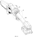
FIG. 14 is schematic view one of the chainsaw shown inFIG. 10 with part of a handle omitted. -
FIG. 15 is an enlarged view of part A inFIG. 14 . -
FIG. 16 is a sectional view of part of the structure of the chainsaw shown inFIG. 10 . -
FIG. 17 is schematic view two of the chainsaw shown inFIG. 10 with part of a handle omitted. -
FIG. 18 is an enlarged view of part B inFIG. 17 . -
FIG. 19 is a schematic view of a locking assembly of the chainsaw shown inFIG. 17 . -
FIG. 20 is a schematic view of part of a handle of the chainsaw shown inFIG. 17 . -
FIG. 21 is a schematic view of the chainsaw shown inFIG. 13 from another perspective. -
FIG. 22 is an enlarged view of part C inFIG. 21 . -
FIG. 23 is a schematic view of a nail gun as a fourth example of the present application. -
FIG. 24 is a schematic view of a nail gun as a fourth example of the present application. -
FIG. 25 is a schematic view of a chainsaw in an extended state as a fifth example of the present application. -
FIG. 26 is a schematic view of the chainsaw shown inFIG. 25 in a retracted state. -
FIG. 27 is a side view of the chainsaw and a handheld power tool inFIG. 10 placed on a horizontal plane. -
FIG. 28 is a side view of the chainsaw and the handheld power tool inFIG. 27 in another working state placed on a horizontal plane. -
FIG. 29 is a schematic view of an example of a chainsaw and a handheld power tool in a first working state. -
FIG. 30 is a schematic view of the chainsaw and the handheld power tool inFIG. 29 in a second working state. - In the description of the present application, it is to be noted that orientations or position relations indicated by terms such as "center", "upper", "lower", "left", "right", "front", and "rear" are based on the drawings. These orientations or position relations are intended only to facilitate and simplify the description of the present application and not to indicate or imply that a device or element referred to must have such particular orientations or must be configured or operated in such particular orientations. Thus, these orientations or position relations are not to be construed as limiting the present application. In addition, terms such as "first" and "second" are used merely for the purpose of description or are used for distinguishing between different structures or components, and are not to be construed as indicating or implying relative importance.
-
FIG. 1 shows ahandheld power tool 10 as a first example. Thehandheld power tool 10 is, for example, achainsaw 100 generally configured to prune branches or forest trees. As shown inFIGS. 1 and2 , thechainsaw 100 generally includes abody housing 11, anoutput assembly 13, amotor 14, a power supply device, and the like. Thebody housing 11 has afront part 111, arear part 112, and anintermediate part 113 between thefront part 111 and therear part 112. For thechainsaw 100, theoutput assembly 13 is a cutting assembly and includes achain 132, aguide plate 131 that supports the movement of thechain 132, and aprotective cover 133 that protects the chain. Themotor 14 is disposed in theintermediate part 113 of thebody housing 11 and configured to drive the chain 1132 to move around theguide plate 131 to implement the cutting operation. For example, thebody housing 11 is formed by aleft housing 114 and aright housing 115. In this example, theright housing 115 is configured to accommodate themotor 14, and the axial direction of themotor 14 is basically perpendicular to the plane where theguide plate 131 is located. Theoutput assemblies 13 of other forms ofhandheld power tools 10 than thechainsaw 100 may be different from theoutput assembly 13 of thechainsaw 100. - The
body housing 11 is further formed with ahandle 12 for the user to hold. Thehandle 12 is disposed on the rear side of thebody housing 11. For example, afirst switch 121 is disposed at one end of thehandle 12 facing therear part 112 of thebody housing 11, and acoupling portion 122 for connecting apower supply device 17 is formed at one end of thehandle 12 facing away from therear part 112 of thebody housing 11. Thefirst switch 121 is operable by the user and is configured to control the starting and stopping of themotor 14. In an example, thefirst switch 121 may be configured to adjust the rotational speed of themotor 14. In this example, thefirst motor 121 is a trigger. In other examples, thefirst switch 121 may be a switch that is pushable forward and backward or a switch that is togglable left and right. Thepower supply device 17 is connected to thecoupling portion 122 and configured to supply electrical energy to thechainsaw 100. In this example, the power supply device is configured to be a battery pack. It is to be understood that the power supply device is not limited to the scenario of using the battery pack, and the power may be supplied to the circuit elements through mains power or an alternating current (AC) power supply in conjunction with the corresponding rectifier circuit, filter circuit, and voltage regulator circuit. - The
handle 12 includes aleft handle housing 124 and aright handle housing 125. Theleft handle housing 124 and theright handle housing 125 form anaccommodation space 123. In this example, thefirst switch 121 is connected to anintegrated switch 1211 and configured to control the rotational speed of themotor 14 to control the cutting speed of thechainsaw 100. For example, theintegrated switch 1211 is disposed in theaccommodation space 123 and corresponds to thefirst switch 121. Theaccommodation space 123 further accommodates acircuit board assembly 1221 that corresponds to thecoupling portion 122 and is configured to control the power supply state of thepower supply device 17 or communicate with thepower supply device 17. - In this example, the
handle 12 is formed with or connected to anadjustment device 15. Theadjustment device 15 extends along the direction of a firststraight line 101 and is connected to therear part 112 of thebody housing 11. Theadjustment device 15 has a first state and a second state in the direction of the firststraight line 101.FIG. 1 shows a schematic view of theadjustment device 15 in thechainsaw 100 in the first state, andFIG. 3 shows a schematic view of theadjustment device 15 in thechainsaw 100 in the second state. For example, when theadjustment device 15 is in the first state, at least part of afront end surface 12a of thehandle 12 abuts against therear part 112. It is to be understood that when theadjustment device 15 is in the first state, thefront end surface 12a of thehandle 12 does not abut against therear part 112, but is separated by a relatively short distance. When theadjustment device 15 is in the second state, at least part of theadjustment device 15 is located between therear part 112 of thebody housing 11 and thefront end surface 12a of thehandle 12. It is to be understood that when theadjustment device 15 is in the first state, theadjustment device 15 can be completely disposed in theaccommodation space 123 formed by thehandle 12. When theadjustment device 15 is in the second state, at least part of theadjustment device 15 is located outside theaccommodation space 123 formed by thehandle 12. - For example, as shown in
FIG. 3 , theadjustment device 15 is disposed between thebody housing 11 and thehandle 12. Thehandle 12 is movable relative to therear part 112 along the extension direction of theadjustment device 15. During the movement of thehandle 12, the first distance L between thefront end surface 12a of thehandle 12 and therear part 112 in the front and rear direction is greater than or equal to 0 and less than 1 meter. For example, the first distance L between thefront end surface 12a of thehandle 12 and therear part 112 in the front and rear direction is greater than or equal to 0 and less than 0.8 meters. For example, the first distance L between thefront end surface 12a of thehandle 12 and therear part 112 in the front and rear direction is greater than or equal to 0 and less than 0.6 meters. The first distance L may be understood as the maximum length of the part of theadjustment device 15 located between thehandle 12 and thebody housing 11. That is to say, during the movement of thehandle 12, the maximum distance between thefront end surface 12a of thehandle 12 and therear part 112 of thebody housing 11 in the front and rear direction is greater than or equal to 0 and less than 1 meter. - For example, as shown in
FIG. 4 , theadjustment device 15 includes at least a first connectingrod 151, a second connectingrod 152, and at least one intermediate connectingrod 153. The first connectingrod 151 is fixedly connected to thehandle 12, the second connectingrod 152 is fixedly connected to therear part 121 of thebody housing 11, and the intermediate connectingrod 153 is disposed between the first connectingrod 151 and the second connectingrod 152. In this example, first fixingpins 151a are formed on or connected to the first connectingrod 151, multiple first throughholes 12a are formed inside thehandle 12, and two ends of thefirst fixing pin 151a are disposed in the first throughhole 12a separately, thereby ensuring that the first connectingrod 151 is fixedly connected to thehandle 12. Similarly,second fixing pins 152a are formed on or connected to the second connectingrod 152, multiple second throughholes 11a are formed on therear part 112 of thebody housing 11, and two ends of thesecond fixing pin 152a are disposed in the second throughhole 11a separately, thereby ensuring that the second connectingrod 152 can be fixedly connected to thebody housing 11. It is to be understood that many methods in which the first connectingrod 151 is fixed to thehandle 12 and the second connectingrod 152 is fixed to therear part 121 of thebody housing 11 exist, which are not limited here. Of course, those skilled in the art may provide a non-fixed connection method, for example, the first connecting rod can be slidably connected to the handle, or other examples, which are not limited here. - As shown in
FIGS. 2 and5 , when theadjustment device 15 is in the first state, theadjustment device 15 can be completely disposed in theaccommodation space 123 formed by thehandle 12. For example, the intermediate connectingrod 153 is sleeved on the second connectingrod 152, and the first connectingrod 151 is sleeved on the intermediate connectingrod 153. It is to be understood that one intermediate connectingrod 153 may be provided. Of course, multiple intermediate connectingrods 153 may be provided. When multiple intermediate connecting rods are provided, the multiple intermediate connecting rods are sleeved together. - Referring to
FIGS. 4 and6 , theadjustment device 15 further includes multiple locking members. The second connectingrod 152 and each intermediate connectingrod 153 are provided with the locking members. For example, the intermediate connectingrod 153 close to the first connectingrod 151 is used as an example for the detailed description of the working principle and function of the locking member. - As shown in
FIG. 6 , a first limitingmember 1531 is formed on or connected to the intermediate connectingrod 152. The first limitingmember 1531 has a first state and a second state in the direction of a secondstraight line 102. A first limiting portion is formed on the first connectingrod 151. For example, the first limiting portion is optionally configured to be a first limitinghole 151b. When theadjustment device 15 is in the first state, the first limitingmember 1531 on the intermediate connectingrod 153 is in the first state. At this time, the first limitingmember 1531 is located outside the first limitinghole 151b, and the first connectingrod 151 and the intermediate connectingrod 153 are movable relatively along the first direction D1 or the second direction D2. When theadjustment device 15 is in the second state, the first limitingmember 1531 on the intermediate connecting rod 154 is in the second state. At this time, the first limitingmember 1531 is disposed in the first limitinghole 151b, and the first connectingrod 151 and the intermediate connecting rod are relatively fixed. - In some examples, when the
adjustment device 15 is in the second state, theadjustment device 15 has at least a first length and a second length in the direction of the firststraight line 101. The first length is less than the second length. For example, when theadjustment device 15 has the first length, asecond locking member 1521 is disposed at a limiting portion of the intermediate connectingrod 153, and the intermediate connectingrod 153 and the second connectingrod 152 are fixedly connected through thesecond locking member 1521. When theadjustment device 15 has the second length, afirst locking member 1531 is disposed at a limiting portion of the first connectingrod 151, and the first connectingrod 151 and the intermediate connectingrod 153 are fixedly connected through thefirst locking member 1521. - For example, as shown in
FIG. 7A , when theadjustment device 15 has the first length in the direction of the firststraight line 101, the second connectingrod 152 and the intermediate connectingrod 153 close to the second connectingrod 152 are relatively fixed under the action of the locking member. Referring toFIG. 7B , when theadjustment device 15 has the second length in the direction of the firststraight line 101, all the locking members in theadjustment device 15 are located in the corresponding limiting holes. In this example, as shown inFIG. 3 , when theadjustment device 15 has the second length in the direction of the firststraight line 101, the first distance L between the grip center A of thehandle 12 and the center B of theguide plate 131 is configured to be less than or equal to 1 meter. - Referring to
FIGS. 1 ,2 , and8 , thechainsaw 100 further includes anadjustment switch 17 partially disposed in agroove 1241 formed by theleft handle housing 124. Theadjustment switch 17 is disposed on thehandle 12. Theadjustment switch 17 has a locking state and an unlocking state. For example, when theadjustment switch 17 is in the unlocking state, thehandle 12 is movable relative to therear part 112 of thebody housing 11 along the direction of the firststraight line 101. For example, theadjustment switch 17 includes a push rod 171 for the user to operate. When the user presses the push rod 171, theadjustment switch 17 is in the unlocking state; and when the user releases the push rod 171, theadjustment switch 17 is in the locking state. For example, theadjustment switch 17 further includes a return spring 172. When the user releases the push rod 171, the adjustment switch 171 returns to the locking state from the unlocking state under the action of the return spring 172. - For example, as shown in
FIG. 8 , theadjustment device 15 is provided with multiple locking holes 1532. When theadjustment switch 17 is in the locking state, a lockingpost 173 of theadjustment switch 17 is located in one of the multiple lockingholes 1532 so that thehandle 12 and thebody housing 11 cannot move relative to each other. When theadjustment switch 17 is in the unlocking state, the lockingpost 173 of theadjustment switch 17 is disengaged from thelocking hole 1532 so that thehandle 12 and thebody housing 11 are movable relatively in the direction of the firststraight line 101. It is to be understood that many methods for implementing the adjustment switch exist. - As a second example of the
handheld power tool 10, as shown inFIGS. 9A and 9B , thehandheld power tool 10 is, for example,electric scissors 10 generally configured to prune branches or forest trees. The electric scissors come in many shapes and types. Theelectric scissors 10 in this example include abody housing 1 and a motor (not shown in the figure) mounted in thebody housing 1. The cutter part of apruner 10 is formed by a fixedblade 3 and amovable blade 4. The fixedblade 3 is fixedly mounted relative to thehousing 1, and themovable blade 4 is connected to the motor through a power transmission device. Aknife edge 5 is formed between the fixedblade 3 and themovable blade 4. Aswitch 6 is mounted on thebody housing 1. To be suitable for different working places, thepruner 10 is powered by the battery pack mounted at the end of thehandle 12. Thepruner 10 further includes ahandle 7 for the user to hold and anadjustment device 8. - For example, the adjustment device is disposed between the
body housing 1 and thehandle 7. Thehandle 7 is movable relative to thebody housing 1 along the extension direction of theadjustment device 8. Theadjustment device 8 is telescopic to a first state and a second state along the extension direction of theadjustment device 8.FIG. 9A shows a schematic view of theelectric scissors 10 when theadjustment device 8 is in the first state.FIG. 9B shows a schematic view of theelectric scissors 10 when theadjustment device 8 is in the second state. When theadjustment device 8 is in the first state, the distance between afront end surface 7a of thehandle 7 and the rear part of thebody housing 1 is the shortest. When the adjustment device is in the second state, the part of the adjustment device located between the front end surface of the handle and the rear part of the body housing has at least a first length and a second length, and the second length is greater than the first length. During the movement of thehandle 7, the shortest distance between thefront end surface 7a of thehandle 7 and the rear end surface of thebody housing 1 in the front and rear direction is greater than or equal to 0 and less than or equal to 0.03 meters. For example, the shortest distance between thefront end surface 7a of thehandle 7 and the rear end surface of thebody housing 1 in the front and rear direction is greater than or equal to 0 and less than or equal to 0.02 meters. The shortest distance between thefront end surface 7a of thehandle 7 and the rear end surface of thebody housing 1 in the front and rear direction is greater than or equal to 0 and less than or equal to 0.01 meters. In some examples, thehandle 7 is formed with an accommodation space, and when theadjustment device 8 is in the first state, theadjustment device 8 can be completely disposed in the preceding accommodation space. - As a third example of the
handheld power tool 10, referring toFIGS. 10 to 13 , thehandheld power tool 10 is, for example, achainsaw 100. Thechainsaw 100 includes a first connectingrod 151 and a second connectingrod 152. The first connectingrod 151 is connected to ahandle 12, and the second connectingrod 152 is connected to the rear part of abody housing 11. In an example, both the first connectingrod 151 and the second connectingrod 152 are aluminum tubes. - The
adjustment device 15 has a first state and a second state so that thechainsaw 100 has a retracted state and an extended state. When theadjustment device 15 is in the first state, thechainsaw 100 is in the retracted state. As shown inFIG. 10 , both the first connectingrod 151 and the second connectingrod 152 are retracted into thehandle 12. When theadjustment device 15 is in the second state, thechainsaw 100 is in the extended state. In this example, the extended state is divided into two cases. In one case, as shown inFIGS. 11 and12 , the second connectingrod 152 extends out of thehandle 12, and the first connectingrod 151 is located inside thehandle 12. In the other case, as shown inFIG. 13 , the first connectingrod 151 extends out of thehandle 12, and the second connectingrod 152 extends out of the first connectingrod 151. - In this example, not only can the
adjustment switch 17 lock the first connectingrod 151 and the second connectingrod 152, but also theadjustment switch 17 and thefirst switch 121 can be interlocked. - For example, as shown in
FIGS. 14 and15 , theadjustment switch 17 includes abutton 173 for the user to operate. When the user presses thebutton 173 to the right side of thechainsaw 100, theadjustment switch 17 is in the unlocking state; and when the user releases thebutton 173, theadjustment switch 17 is in the locking state. Theadjustment switch 17 further includes afirst seesaw 174 and areset torsion spring 175. Thefirst seesaw 174 rotates about a first rotary shaft, and thereset torsion spring 175 is sleeved on the first rotary shaft. When the user presses thebutton 173, thebutton 173 presses one end of thefirst seesaw 174 to lift the other end of thefirst seesaw 174; and when the user releases thebutton 173, under the action of thereset torsion spring 175, thebutton 173 and thefirst seesaw 174 are reset. - The
adjustment device 15 is provided with alocking hole 1532, and the end of thefirst seesaw 174 can extend into thelocking hole 1532 so that theadjustment device 15 is locked, and thehandle 12 and thebody housing 11 cannot move relative to each other. According to actual requirements, the first connectingrod 151 and the second connectingrod 152 are both provided with lockingholes 1532, and when thechainsaw 100 is in a fully retracted state, onelocking hole 1532 on the first connectingrod 151 is aligned with onelocking hole 1532 on the second connectingrod 152 so that thefirst seesaw 174 can lock the first connectingrod 151 and the second connectingrod 152 at the same time. - A
stop portion 1731 is disposed on thebutton 173. When the user presses thebutton 173, thestop portion 1731 is located on the movement path of thefirst switch 121 so that thefirst switch 121 cannot be pressed, and thus thefirst switch 121 is restricted from implementing a power-on function. For example, thestop portion 1731 is located on a side of thebutton 173 facing thefirst switch 121, and thefirst seesaw 174 is located on a side of thebutton 173 facing away from thefirst switch 121. Since when theadjustment switch 17 is in the unlocking state, thehandle 12 is movable relative to thebody housing 11 along the direction of the first straight line, to ensure safety, the power-on function of thefirst switch 121 is limited. - As shown in
FIG. 15 , when theadjustment switch 17 is in the locking state, the end of thefirst seesaw 174 extends out of thelocking hole 1532, the relative positions of thehandle 12 and thebody housing 11 are fixed, and thefirst switch 121 can implement the power-on function. When theadjustment switch 17 is in the unlocking state, thefirst switch 121 is locked by theadjustment switch 17 so that thefirst switch 121 cannot be pressed, and thus thefirst switch 121 cannot implement the power-on function. For example, as shown inFIG. 16 , the wire is inserted through thehandle 12 and theadjustment device 15, and the wire connects themotor 14 to the power supply device. For example, the wire is a spring wire so that the wire can be lengthened and shortened as theadjustment device 15 is lengthened and shortened, and thus the power supply stability is not affected. - Referring to
FIGS. 17 to 20 , a locking assembly is disposed between the first connectingrod 151 and the second connectingrod 152. When both the first connectingrod 151 and the second connectingrod 152 extend out of thehandle 12, the first connectingrod 151 and the second connectingrod 152 are locked by the locking assembly. When the second connectingrod 152 extends out of thehandle 12 and the first connectingrod 151 retracts into thehandle 12, the locking assembly provides resistance in the extension direction for the first connectingrod 151. - For example, the locking assembly includes a
second seesaw 192 and aprotective plate 191 disposed on the second connectingrod 152. Thesecond seesaw 192 and theprotective plate 191 are rotatably connected through a second rotary shaft. Aresistance spring 193 is disposed on theprotective plate 191 and sandwiched between theprotective plate 191 and one end of thesecond seesaw 192. The first connectingrod 151 is provided with a limitinghole 1511, and one end of thesecond seesaw 192 facing away from the resistance spring can extend into the limitinghole 1511 so that the first connectingrod 151 and the second connectingrod 152 are locked. - A limiting
block 126 is disposed on the inner wall of thehandle 12. The limitingblock 126 can abut against thesecond seesaw 192 and compress theresistance spring 193. When the second connectingrod 152 extends out of thehandle 12 and the first connectingrod 151 retracts into thehandle 12, the limitingblock 126 abuts against one end of thesecond seesaw 192 and compresses theresistance spring 193 so that theresistance spring 193 provides resistance to prevent the first connectingrod 151 from sliding out of thehandle 12. At this time, if the user needs to pull out the first connectingrod 151, the user needs to overcome the resistance of theresistance spring 193. The advantage of this setting is that the operating feel of the user is improved. When the user feels resistance when pulling out the second connectingrod 152, it can be considered that the second connectingrod 152 has been pulled out in place. - The
protective plate 191 covers two sides of thesecond seesaw 192 to prevent the following: branches and the like are accidentally in contact with thesecond seesaw 192, causing theresistance spring 193 to be pressed down due to the accidental contact when theresistance spring 193 does not need to be compressed, resulting in safety hazards. - The
protective plate 191 and the second connectingrod 152 are engaged through anelastic snap 194. During retraction, after the limitingblock 126 abuts against thesecond seesaw 192, theprotective plate 191 is fixed, the second connectingrod 152 continues retracting, and the external force applied by the user to the second connectingrod 152 overcomes the elastic force of theelastic snap 194. - As shown in
FIGS. 21 to 23 , a clamping structure is further disposed between thehandle 12 and thebody housing 11. The clamping structure includes a clampingtooth 127 on thebutton 173 and a snap groove at the rear end of thebody housing 11. For example, thebody housing 11 is provided with aprotrusion 117, and the snap groove is opened on theprotrusion 117. When the user presses thebutton 173, the clampingtooth 127 is disengaged from the snap groove, and thebody housing 11 can slide relative to thehandle 12; and when both the first connectingrod 151 and the second connectingrod 152 retract and the user releases thebutton 173, the clampingtooth 127 and the snap groove are clamped so that thebody housing 11 and thehandle 12 are locked. - In the
chainsaw 100 provided in this example, when thechainsaw 100 is in the fully retracted state, onelocking hole 1532 on the first connectingrod 151 is aligned with onelocking hole 1532 on the second connectingrod 152, and the end of thefirst seesaw 174 extends into the lockingholes 1532 so that the first connectingrod 151 and the second connectingrod 152 are locked. At the same time, the clampingtooth 127 is clamped into the snap groove so that thebody housing 11 and thehandle 12 are locked. - When the
chainsaw 100 needs to be unfolded, the user presses thebutton 173, and thebutton 173 presses one end of thefirst seesaw 174 to disengage the other end of thefirst seesaw 174 from the locking holes 1532. At this time, thehandle 12 and thebody housing 11 are movable along the direction of the firststraight line 101. After the user applies a force to thebody housing 11 to pull out the second connectingrod 152, the second connectingrod 152 extends out of thehandle 12, and the first connectingrod 151 is located inside thehandle 12. At this time, if the user releases thebutton 173, under the action of thereset torsion spring 175, thebutton 173 and thefirst seesaw 174 are reset, and the end of thefirst seesaw 174 extends into thelocking hole 1532 of the second connectingrod 152 to lock the second connectingrod 152. - When the user presses the
button 173 again, thebutton 173 presses one end of thefirst seesaw 174 to disengage the other end of thefirst seesaw 174 from thelocking hole 1532 of the second connectingrod 152. At this time, thehandle 12 and thebody housing 11 are movable along the direction of the firststraight line 101. At this time, the user needs to apply a force to the second connectingrod 152 and the first connectingrod 151 along the length direction of the second connectingrod 152 so that thesecond seesaw 192 is disengaged from the limitingblock 126, and the first connectingrod 151 is pulled out. At this time, one end of thesecond seesaw 192 facing away from the resistance spring extends into the limitinghole 1511 so that the first connectingrod 151 and the second connectingrod 152 are locked stably. - When the first connecting
rod 151 extends out of thehandle 12, thechainsaw 100 is in a fully extended state. If the user releases thebutton 173, under the action of thereset torsion spring 175, thebutton 173 and thefirst seesaw 174 are reset, and the end of thefirst seesaw 174 extends into thelocking hole 1532 of the first connectingrod 151 to lock the first connectingrod 151. - When the
chainsaw 100 needs to be stored, the user presses thebutton 173, and thebutton 173 presses one end of thefirst seesaw 174 to disengage the other end of thefirst seesaw 174 from thelocking hole 1532 of the first connectingrod 151. Since one end of thesecond seesaw 192 is still located in the limitinghole 1511, the first connectingrod 151 and the second connectingrod 152 are locked. The first connectingrod 151 retracts into thehandle 12 first, and when the limitingblock 126 is in contact with thesecond seesaw 192, the limitingblock 126 abuts against one end of thesecond seesaw 192 to disengage the other end of thesecond seesaw 192 from the limitinghole 1511. At this time, the second connectingrod 152 is slidable relative to the first connectingrod 151, and the second connectingrod 152 retracts into the first connectingrod 151. The user releases thebutton 173. Under the action of thereset torsion spring 175, thebutton 173 and thefirst seesaw 174 are reset, the end of thefirst seesaw 174 extends into thelocking hole 1532 of the second connectingrod 152, and at the same time, the clampingtooth 127 and the snap groove are engaged. - In conjunction with
FIGS. 10 ,12, and 13 , thehandheld power tool 10 includes theoutput assembly 13 connected to the body housing and configured to perform an output operation; the adjustment device is disposed between the body housing and the handle; the handle is movable relative to the body housing along the extension direction of the adjustment device; and the distance between the frontmost side of the power tool and the rearmost side of thefirst switch 121 is defined as the effective length of the power tool, thehandheld power tool 10 includes at least a first effective length T1 and a second effective length T2, and thehandheld power tool 10 can work normally at both the first effective length T1 and the second effective length T2. That is to say, thehandheld power tool 10 has at least a first working state and a second working state. When thehandheld power tool 10 is in the first working state, thehandheld power tool 10 has the first effective length T1; and when thehandheld power tool 10 is in the second working state, thehandheld power tool 10 has the second effective length T2. The first effective length T1 is less than or equal to 60 cm, and the second effective length T2 is greater than the first effective length T1. - The effective length of the chainsaw refers to the distance between the frontmost side of the
chain 132 and the rearmost side of thefirst switch 121. If the switch is thefirst switch 121 shown in the figure, the rearmost side of the switch is the rearmost side of thefirst switch 121. If the switch is a switch that is pushable forward and backward, the "rearmost side of the switch" in the effective length refers to the rearmost side of the switch when the switch is in the rearmost gear. That is to say, if thefirst switch 121 is a switch that is pushable forward and backward, the change in the position of thefirst switch 121 in the front and rear direction due to the turn-on of the switch is not included in the change in effective length. - For the power tool with a saw blade attachment such as a reciprocating saw and a jigsaw, the effective length refers to the frontmost housing of the power tool without the saw blade attachment and the rearmost side of the
first switch 121. For the power tool with a chain such as a chainsaw, the effective length refers to the chain and the rearmost side of thefirst switch 121. - As shown in
FIG. 12 , in this example, the distance between the frontmost side of thechain 132 and the rearmost side of thefirst switch 121 is T2, and T2 is about between 50 cm and 70 cm. In this example, T2 is about 65 cm. Both the first connectingrod 151 and the second connectingrod 152 can completely enter thehandle 12 when retracted, thereby not only ensuring the portability of thechainsaw 100 but also ensuring the retractability of thechainsaw 100. In some examples, T2 may be 58 cm, 60 cm, 62 cm, 68 cm, or the like. - In an example, T1 is greater than or equal to 25 cm and less than or equal to 50 cm. The power tool is moderately long and telescopic, so the power tool can adapt to a variety of working conditions.
- In an example, the difference between the second effective length T2 and the first effective length T1 is greater than or equal to 5 cm. In an example, the difference between the second effective length T2 and the first effective length T1 is greater than or equal to 10 cm. In an example, the difference between the second effective length T2 and the first effective length T1 is greater than or equal to 15 cm. In an example, the difference between the second effective length T2 and the first effective length T1 is greater than or equal to 20 cm.
- The power tool further includes the greatest third effective length T3, and the difference between the third effective length T3 and the second effective length T2 is greater than or equal to 10 cm.
- The power tool further includes the
coupling portion 122 configured to mount a battery pack, and the total weight of the power tool to which the battery pack is mounted is less than or equal to 6 kg. The whole machine is relatively light in weight, is portable in operation, and can adapt to a wide range of applications. In some examples, the total weight may be 5 kg or 4 kg. In the third example, the total weight is about 2.2 kg. - It is to be noted that the technical solutions involved in the present application can be applied to the following types of power tools: a nail gun, a trimming machine, a one-handed reciprocating saw, a blower, a pruner, a hedge trimmer, a mower, a one-handed circular saw, a cleaning brush, and the like. The power tools are telescopic and can adapt to a variety of work conditions and workspaces.
- As a fourth example of the
handheld power tool 10, referring toFIGS. 23 and24 , theadjustment device 15, theadjustment switch 17, the locking assembly, and the clamping structure provided in the third example above can be used in otherhandheld power tools 10, such as the nail gun shown inFIG. 23 and the reciprocating saw shown inFIG. 24 . For example,FIG. 24 shows a one-handed mini reciprocating saw, which is also a small-sized reciprocating saw. - In
FIG. 23 , theadjustment switch 17 is disposed on thehandle 12. It is to be noted that when the solution disclosed in example three is applied in the form of an extension rod attachment, thehandle 12 of the extension rod attachment is further provided with theadditional adjustment switch 17 that is different from the switch provided on the original power tool. Theadjustment switch 17 is electrically connected to the body housing of thehandheld power tool 10. - As a fifth example of the
handheld power tool 10, referring toFIGS. 25 and26 , thechainsaw 100 further includes a housing disposed on a side of thehandle 12 and connected to thehandle 12, one end of theadjustment device 15 is located in the housing, and the other end of theadjustment device 15 is connected to thebody housing 11. - The
adjustment device 15 includes at least the first connectingrod 151, the second connectingrod 152, and at least one intermediate connectingrod 153. The first connectingrod 151 is connected to the housing, the second connectingrod 152 is connected to thebody housing 11, and the intermediate connectingrod 153 is disposed between the first connectingrod 151 and the second connectingrod 152. For the connection manner of the first connectingrod 151, the second connectingrod 152, and the intermediate connectingrod 153, reference may be made to example one and example three, and the details are not repeated here. - A
spring wire 18 is inserted through the housing and theadjustment device 15. One end of thespring wire 18 is connected to the motor, and the other end of the spring wire is connected to the power supply device. - In an example, T1 is greater than or equal to 10 cm and less than or equal to 40 cm. In this case, the length of the
handheld power tool 10 from the grip part of the hand of the user to the frontmost side of theoutput assembly 13 for operation is smaller, that is to say, the volume of the tool is smaller. Therefore, when the solutions involved in the present application are adopted, thehandheld power tool 10 is more compact and convenient, can be freely telescopic, and can satisfy the requirements of various working conditions. - It is to be noted that the technical solutions in the five examples described above can be adopted in conjunction with each other, and some repetitive features are not repeatedly described at the time of writing the present application.
- As shown in
FIGS. 27 and28 , when thehandheld power tool 10 or thechainsaw 100 is placed on a horizontal plane P, thebody housing 11 has a protrudingsupport housing 116 so that thechain 132 will not touch the horizontal plane P when thechainsaw 100 is placed on the horizontal plane. At the other end of thechainsaw 100, that is, on a side where abattery pack 130 is mounted, thebattery pack 130 may touch the horizontal plane P. When thehandheld power tool 10 or thechainsaw 100 is placed in this manner, the distance of the entirehandheld power tool 10 orchainsaw 100 in the front and rear direction is defined as the total length of thehandheld power tool 10 orchainsaw 100. The total length is adjustable, and the minimum value of the total length is less than 1.2 m. - The
handheld power tool 10 has at least two working states, that is, the first working state and the second working state. When thehandheld power tool 10 is in the first working state, thehandheld power tool 10 has a first total length M1; and when thehandheld power tool 10 is in the second working state, the handheld power tool has a second total length M2. The first total length M1 is less than or equal to 1.2 m, and the second total length M2 is greater than the first total length M1. In an example, the first total length M1 is less than or equal to 1 m. In an example, the first total length M1 is less than or equal to 0.8 m. In an example, the first total length M1 is less than or equal to 0.7 m. In an example, the first total length M1 is less than or equal to 0.6 m. - In an example, the first total length M1 is less than or equal to 1 m, and the first effective length T1 is less than or equal to 60 cm. In an example, the first total length M1 is less than or equal to 1 m, and the first effective length T1 is less than or equal to 50 cm. In an example, the difference between the second total length M2 and the first total length M1 is greater than or equal to 10 cm. In an example, the difference between the second total length M2 and the first total length M1 is greater than or equal to 20 cm.
- It is to be noted that the minimum value of the total length M refers to the shortest total length when the
adjustment device 15 of thehandheld power tool 10 orchainsaw 100 retracts along the front and rear direction of the tool. The content in the example shown inFIG. 27 that is repeated in the examples shown inFIGS. 1 to 26 is not repeatedly described. - The following is a supplementary description of the
first switch 121. Thefirst switch 121 can at least control the starting and stopping of the motor. That is to say, thefirst switch 121 may have other functions, such as adjusting the rotational speed of the motor. At least onefirst switch 121 may be provided. - The examples shown in
FIGS. 29 and30 are described below. As shown inFIG. 29 , ahandheld power tool 10a includes anoutput assembly 13a and ahandle 12a for the user to hold. Thehandheld power tool 10a has at least two switches that can control the starting and stopping of the motor, that is, asecond switch 1212 and afirst switch 1213. Thesecond switch 1212 and thefirst switch 1213 are spaced apart from each other on thehandle 12a. Thehandle 12a may be divided into afirst handle portion 1201 and asecond handle portion 1202. Thefirst handle portion 1201 is closer to theoutput assembly 13a than thesecond handle portion 1202. Thesecond switch 1212 is disposed on thefirst handle portion 1201, and thefirst switch 1213 is disposed on thesecond handle portion 1202. - An
adjustment device 15a is further disposed in thehandle 12a. When thehandheld power tool 10a is extended from the retracted state shown inFIG. 29 to the extended state shown inFIG. 30 , theadjustment device 15a increases the distance between thefirst handle portion 1201 and thesecond handle portion 1202. In an example, theadjustment device 15a may be a telescopic rod assembly similar to or different from the preceding structure. In the retracted state shown inFIG. 29 , the user may hold the hand on thefirst handle portion 1201 and control the starting and stopping of the motor by operating thesecond switch 1212. In the extended state shown inFIG. 30 , the user may hold the hand on thesecond handle portion 1202 and control the starting and stopping of the motor by operating thefirst switch 1213. - The distance between the rearmost side of the
first switch 1213 and the frontmost side of thehandheld power tool 10a is adjustable. The distance between the frontmost side of thehandheld power tool 10a and the rearmost side of the first switch is defined as the effective length of thehandheld power tool 10a. Thehandheld power tool 10a includes at least the first effective length T1 and the second effective length T2. Thehandheld power tool 10a has at least two working states, that is, the first working state and the second working state. When thehandheld power tool 10a is in the first working state, thehandheld power tool 10a has the first effective length T1; and when thehandheld power tool 10a is in the second working state, thehandheld power tool 10a has the second effective length T2. The first effective length T1 is less than or equal to 1 m, and the second effective length T2 is greater than the first effective length T1. It is to be noted that the definition of the first effective length T1 and the second effective length T2 in this case is consistent with the preceding description, and the details are not repeated here. - For the example disclosed in
FIGS. 29 and30 , one usage situation may be that in the retracted state ofFIG. 29 , the user uses thesecond switch 1212; and in the extended state ofFIG. 30 , the user uses thefirst switch 1213. It is to be noted that although only one of thefirst switch 1213 and thesecond switch 1212 can be activated at a moment, and the user controls the starting and stopping of the motor, both thefirst switch 1213 and thesecond switch 1212 can be used for controlling the starting and stopping of the motor. - As shown in
FIGS. 6 and13 , theadjustment device 15 includes atelescopic rod assembly 150. Theadjustment device 15 can enable thehandheld power tool 10 to have at least two working states, that is, the first working state and the second working state. In some examples, theadjustment device 15 may not include thetelescopic rod assembly 150, and other structures may be used to adjust the overall length of thehandheld power tool 10. - In addition, one-handed saws are common in the field of power tools. A one-handed saw is generally a sawing power tool that is operable by the user with just one hand. According to different purposes and working conditions, the one-handed saws may generally be divided into a one-handed chainsaw, a mini chainsaw, a one-handed reciprocating saw, a mini reciprocating saw, a one-handed electric circular saw, a mini electric circular saw, and the like. Two hands are generally required to hold the pole saw. The one-handed chainsaw and the mini chainsaw tend to be shorter in length than the pole saw and are generally configured to cut items at close range. In the technical solutions involved in the present application, the chainsaw can be used in a variety of working conditions, the limit on the distance between the object to be cut and the user is smaller, and the chainsaw may be long or short, flexible in operation, and suitable for a variety of working conditions.
- With continued reference to
FIGS. 27 and28 , the present application discloses a one-handed saw. The one-handed saw includes a motor accommodated in a body housing; a handle for a user to hold; and an output assembly for performing an output operation. When the one-handed saw is placed on a horizontal plane, the maximum distance of the one-handed saw along the direction parallel to the horizontal plane is defined as the total length of the one-handed saw, and the total length is adjustable.
Claims (20)
- A handheld power tool, comprising:a motor;a handle for a user to hold, wherein a first switch is disposed on the handle and configured to at least control starting and stopping of the motor; andan output assembly configured to perform an output operation;wherein the handheld power tool further comprises:an adjustment device comprising a telescopic rod assembly, wherein a length of the adjustment device changes so that the handheld power tool has at least two working states, that is, a first working state and a second working state;wherein a distance between a frontmost side of the handheld power tool and a rearmost side of the first switch is defined as an effective length of the handheld power tool; wherein when the handheld power tool is in the first working state, the handheld power tool has a first effective length (T1); and when the handheld power tool is in the second working state, the handheld power tool has a second effective length (T2); wherein the first effective length (T1) is less than or equal to 1 m, and the second effective length (T2) is greater than the first effective length (T1).
- The handheld power tool of claim 1, wherein a difference between the second effective length (T2) and the first effective length (T1) is greater than or equal to 10 cm.
- The handheld power tool of claim 1, wherein a difference between the second effective length (T2) and the first effective length (T1) is greater than or equal to 20 cm.
- The handheld power tool of claim 1, further comprising a third effective length (T3), wherein the third effective length (T3) is greater than the second effective length (T2), and a difference between the third effective length (T3) and the second effective length (T2) is greater than or equal to 10 cm.
- The handheld power tool of claim 1, further comprising a coupling portion configured to mount a battery pack, wherein total weight of the handheld power tool to which the battery pack is mounted is less than or equal to 6 kg.
- The handheld power tool of claim 1, wherein the adjustment device is telescopic to a first state and a second state along a front and rear direction of the handheld power tool.
- The handheld power tool of claim 1, further comprising an adjustment switch, wherein at least part of the adjustment switch is disposed on the handle; a stop portion is disposed on the adjustment switch; and when the adjustment switch is in an unlocked state, the stop portion is located on a movement path of the first switch controlling the starting and stopping of the motor, and at this time, the first switch is restricted from implementing a function of starting the motor.
- The handheld power tool of claim 7, wherein the adjustment device is provided with a locking hole, the adjustment switch further comprises a button for the user to operate, a first seesaw rotatably connected to the handle, and a reset torsion spring connected to the first seesaw, the button is capable of pressing one end of the first seesaw, and another end of the first seesaw is selectively inserted into the locking hole.
- The handheld power tool of claim 8, wherein the adjustment device comprises a first connecting rod connected to the handle and provided with the locking hole.
- The handheld power tool of claim 9, further comprising a body housing, wherein the motor is disposed in the body housing, the output assembly is at least partially disposed in the body housing, and the adjustment device further comprises a second connecting rod connected to the body housing.
- The handheld power tool of claim 10, wherein a locking assembly is disposed between the first connecting rod and the second connecting rod, and when both the first connecting rod and the second connecting rod extend out of the handle, the locking assembly locks the first connecting rod and the second connecting rod.
- The handheld power tool of claim 1, further comprising a coupling portion configured to mount a battery pack, wherein the handheld power tool further comprises a spring wire, the spring wire is inserted through the handle and the adjustment device, one end of the spring wire is electrically connected to the motor, and another end of the spring wire is electrically connected to the battery pack.
- The handheld power tool of claim 1, further comprising a power supply device for supplying electric power to at least the motor, wherein the power supply device is detachably connected to a rear part of the handle.
- The handheld power tool of claim 1, wherein the first effective length (T1) is less than or equal to 60 cm.
- The handheld power tool of claim 1, wherein the first effective length (T1) is less than or equal to 50 cm.
- The handheld power tool of claim 1, wherein the adjustment device is at least partially disposed between the output assembly and the handle.
- The handheld power tool of claim 1, wherein the handheld power tool is a chainsaw, electric scissors, a nail gun, or a reciprocating saw.
- A handheld power tool, comprising:a motor accommodated in a body housing;a handle for a user to hold; andan output assembly configured to perform an output operation;wherein when the handheld power tool is placed on a horizontal plane, a maximum distance of the handheld power tool along a direction parallel to the horizontal plane is defined as a total length of the handheld power tool, and the total length is adjustable; andthe handheld power tool has at least two working states, that is, a first working state and a second working state; wherein when the handheld power tool is in the first working state, the handheld power tool has a first total length (M1); and when the handheld power tool is in the second working state, the handheld power tool has a second total length (M2); wherein the second total length (M2) is greater than the first total length (M1), and the first total length (M1) is less than 1.2 m.
- The handheld power tool of claim 18, comprising only a first switch for controlling starting and stopping of the motor, wherein the first switch is capable of controlling the starting and stopping of the motor when the handheld power tool is in different working states.
- A one-handed saw, comprising:a motor accommodated in a body housing;a handle for a user to hold; andan output assembly configured to perform an output operation;wherein when the one-handed saw is placed on a horizontal plane, a maximum distance of the one-handed saw along a direction parallel to the horizontal plane is defined as a total length of the one-handed saw, and the total length is adjustable.
Applications Claiming Priority (3)
| Application Number | Priority Date | Filing Date | Title |
|---|---|---|---|
| CN202210565167 | 2022-05-23 | ||
| CN202211130489 | 2022-09-16 | ||
| PCT/CN2023/094676 WO2023226840A1 (en) | 2022-05-23 | 2023-05-17 | Handheld electric tool and single-handed saw |
Publications (2)
| Publication Number | Publication Date |
|---|---|
| EP4437835A1 true EP4437835A1 (en) | 2024-10-02 |
| EP4437835A4 EP4437835A4 (en) | 2025-05-14 |
Family
ID=88793352
Family Applications (1)
| Application Number | Title | Priority Date | Filing Date |
|---|---|---|---|
| EP23810913.6A Pending EP4437835A4 (en) | 2022-05-23 | 2023-05-17 | Handheld electric tool and single-handed saw |
Country Status (3)
| Country | Link |
|---|---|
| EP (1) | EP4437835A4 (en) |
| CN (1) | CN117099580A (en) |
| WO (1) | WO2023226840A1 (en) |
Cited By (1)
| Publication number | Priority date | Publication date | Assignee | Title |
|---|---|---|---|---|
| US12599065B1 (en) * | 2024-12-09 | 2026-04-14 | Sihao Huang | Telescopic structure, telescopic blower, and telescopic electric chainsaw |
Family Cites Families (14)
| Publication number | Priority date | Publication date | Assignee | Title |
|---|---|---|---|---|
| US20050249564A1 (en) * | 2004-05-05 | 2005-11-10 | One World Technologies Limited | Auxiliary handle for a portable power tool |
| US20080173138A1 (en) * | 2006-08-15 | 2008-07-24 | Dayton Douglas C | Systems and methods of a vacuum cup bulb changer power tool system with interchangeable functional attachments |
| US9591809B2 (en) * | 2007-02-06 | 2017-03-14 | Mtd Products Inc | Split power tool |
| CN201612046U (en) * | 2009-12-15 | 2010-10-27 | 南京德朔实业有限公司 | Pruners with Extension Rods |
| CN103181262A (en) * | 2011-12-30 | 2013-07-03 | 苏州宝时得电动工具有限公司 | Garden tool |
| ES2658617T3 (en) * | 2013-09-26 | 2018-03-12 | Ningbo Zhenhai Greatwall Automobile Parts Factory | Electric tree cutting device |
| AU2017336937A1 (en) * | 2016-09-29 | 2019-03-28 | Mtd Products Inc | Split power tool |
| CN108240345B (en) * | 2016-12-23 | 2024-02-20 | 苏州宝时得电动工具有限公司 | Electric tool |
| IT201800010192A1 (en) * | 2018-11-09 | 2020-05-09 | Archman S R L | TRUNK OR LOPPER |
| CN113305789B (en) * | 2020-02-27 | 2022-09-20 | 南京泉峰科技有限公司 | Long rod type electric tool |
| CN111436292B (en) * | 2020-03-26 | 2024-12-24 | 浙江动一新能源动力科技股份有限公司 | An all-in-one work tool |
| TWM612629U (en) * | 2020-12-28 | 2021-06-01 | 合成園藝工具股份有限公司 | Structure of long-armed clipper |
| CN214902338U (en) * | 2021-01-30 | 2021-11-30 | 东莞市嘉航实业有限公司 | A new type of telescopic rod and sugarcane trimmer provided with the telescopic rod |
| CN113875428B (en) * | 2021-11-15 | 2024-09-27 | 上海士商进出口有限公司 | A high branch saw |
-
2023
- 2023-05-17 WO PCT/CN2023/094676 patent/WO2023226840A1/en not_active Ceased
- 2023-05-17 EP EP23810913.6A patent/EP4437835A4/en active Pending
- 2023-05-19 CN CN202310574706.8A patent/CN117099580A/en active Pending
Cited By (1)
| Publication number | Priority date | Publication date | Assignee | Title |
|---|---|---|---|---|
| US12599065B1 (en) * | 2024-12-09 | 2026-04-14 | Sihao Huang | Telescopic structure, telescopic blower, and telescopic electric chainsaw |
Also Published As
| Publication number | Publication date |
|---|---|
| WO2023226840A1 (en) | 2023-11-30 |
| EP4437835A4 (en) | 2025-05-14 |
| CN117099580A (en) | 2023-11-24 |
Similar Documents
| Publication | Publication Date | Title |
|---|---|---|
| US20240351182A1 (en) | Handheld power tool and one-handed saw | |
| CN101056745B (en) | Blades for power utility knives | |
| CA2432503C (en) | Power tool | |
| CN109746877B (en) | Hand-held electric tool | |
| US20160375571A1 (en) | Split power tool | |
| US20230172111A1 (en) | Pole power tool and foldable pole assembly | |
| US7989718B1 (en) | Power control engagement device for a power tool | |
| EP4520493A1 (en) | Chain saw | |
| CN220571063U (en) | Support device and working apparatus having the same | |
| US20200346335A1 (en) | Power head configured to operate multiple tool heads with universal rotary device | |
| EP3669628A1 (en) | Garden tool and control box thereof | |
| US20240208092A1 (en) | Multiple function hair trimmer | |
| US11554474B2 (en) | Mating interface for a power head configured to operate multiple tool attachments | |
| EP1075914B1 (en) | Biscuit jointer | |
| EP0879553A2 (en) | Hedge trimmer | |
| US20200375124A1 (en) | Blower with improved balance and construction | |
| WO2023226840A1 (en) | Handheld electric tool and single-handed saw | |
| CN112335437A (en) | Removable multi-functional gardens of handle instrument of repairing | |
| CN222340087U (en) | Chain saw | |
| EP0979711B1 (en) | Battery powered portable circular saw with depth of cut control | |
| US20240081192A1 (en) | Hedge trimmer | |
| EP1627562A1 (en) | Hedge trimmer | |
| JP5281999B2 (en) | Extension handle used for gardening hair clippers | |
| CN217530757U (en) | Electric tool capable of being lengthened in telescopic mode | |
| CN219395633U (en) | Hedge trimmer convenient to accomodate |
Legal Events
| Date | Code | Title | Description |
|---|---|---|---|
| STAA | Information on the status of an ep patent application or granted ep patent |
Free format text: STATUS: THE INTERNATIONAL PUBLICATION HAS BEEN MADE |
|
| PUAI | Public reference made under article 153(3) epc to a published international application that has entered the european phase |
Free format text: ORIGINAL CODE: 0009012 |
|
| STAA | Information on the status of an ep patent application or granted ep patent |
Free format text: STATUS: REQUEST FOR EXAMINATION WAS MADE |
|
| 17P | Request for examination filed |
Effective date: 20240626 |
|
| AK | Designated contracting states |
Kind code of ref document: A1 Designated state(s): AL AT BE BG CH CY CZ DE DK EE ES FI FR GB GR HR HU IE IS IT LI LT LU LV MC ME MK MT NL NO PL PT RO RS SE SI SK SM TR |
|
| REG | Reference to a national code |
Ref country code: DE Ref legal event code: R079 Free format text: PREVIOUS MAIN CLASS: A01G0003025000 Ipc: A01G0003033000 |
|
| A4 | Supplementary search report drawn up and despatched |
Effective date: 20250414 |
|
| RIC1 | Information provided on ipc code assigned before grant |
Ipc: A01G 3/037 20060101ALI20250408BHEP Ipc: B25F 5/02 20060101ALI20250408BHEP Ipc: A01G 3/08 20060101ALI20250408BHEP Ipc: A01G 3/033 20060101AFI20250408BHEP |
|
| DAV | Request for validation of the european patent (deleted) | ||
| DAX | Request for extension of the european patent (deleted) | ||
| STAA | Information on the status of an ep patent application or granted ep patent |
Free format text: STATUS: EXAMINATION IS IN PROGRESS |
|
| 17Q | First examination report despatched |
Effective date: 20251117 |
|
| GRAP | Despatch of communication of intention to grant a patent |
Free format text: ORIGINAL CODE: EPIDOSNIGR1 |
|
| STAA | Information on the status of an ep patent application or granted ep patent |
Free format text: STATUS: GRANT OF PATENT IS INTENDED |