EP4436319A1 - Luminaires for emergency lighting operation and methods of operating the same - Google Patents
Luminaires for emergency lighting operation and methods of operating the same Download PDFInfo
- Publication number
- EP4436319A1 EP4436319A1 EP23163915.4A EP23163915A EP4436319A1 EP 4436319 A1 EP4436319 A1 EP 4436319A1 EP 23163915 A EP23163915 A EP 23163915A EP 4436319 A1 EP4436319 A1 EP 4436319A1
- Authority
- EP
- European Patent Office
- Prior art keywords
- luminaire
- lighting operation
- supply voltage
- emergency lighting
- unit
- Prior art date
- Legal status (The legal status is an assumption and is not a legal conclusion. Google has not performed a legal analysis and makes no representation as to the accuracy of the status listed.)
- Pending
Links
- 238000000034 method Methods 0.000 title claims description 26
- 238000004891 communication Methods 0.000 claims abstract description 67
- 238000001514 detection method Methods 0.000 claims description 11
- 238000010586 diagram Methods 0.000 description 9
- 238000005286 illumination Methods 0.000 description 4
- 230000007704 transition Effects 0.000 description 3
- 230000000694 effects Effects 0.000 description 2
- 239000003990 capacitor Substances 0.000 description 1
- 230000001419 dependent effect Effects 0.000 description 1
- 238000005516 engineering process Methods 0.000 description 1
- 238000009499 grossing Methods 0.000 description 1
- 230000002028 premature Effects 0.000 description 1
Images


Classifications
-
- H—ELECTRICITY
- H05—ELECTRIC TECHNIQUES NOT OTHERWISE PROVIDED FOR
- H05B—ELECTRIC HEATING; ELECTRIC LIGHT SOURCES NOT OTHERWISE PROVIDED FOR; CIRCUIT ARRANGEMENTS FOR ELECTRIC LIGHT SOURCES, IN GENERAL
- H05B47/00—Circuit arrangements for operating light sources in general, i.e. where the type of light source is not relevant
- H05B47/10—Controlling the light source
- H05B47/105—Controlling the light source in response to determined parameters
- H05B47/11—Controlling the light source in response to determined parameters by determining the brightness or colour temperature of ambient light
-
- H—ELECTRICITY
- H05—ELECTRIC TECHNIQUES NOT OTHERWISE PROVIDED FOR
- H05B—ELECTRIC HEATING; ELECTRIC LIGHT SOURCES NOT OTHERWISE PROVIDED FOR; CIRCUIT ARRANGEMENTS FOR ELECTRIC LIGHT SOURCES, IN GENERAL
- H05B47/00—Circuit arrangements for operating light sources in general, i.e. where the type of light source is not relevant
- H05B47/10—Controlling the light source
- H05B47/105—Controlling the light source in response to determined parameters
- H05B47/115—Controlling the light source in response to determined parameters by determining the presence or movement of objects or living beings
-
- H—ELECTRICITY
- H05—ELECTRIC TECHNIQUES NOT OTHERWISE PROVIDED FOR
- H05B—ELECTRIC HEATING; ELECTRIC LIGHT SOURCES NOT OTHERWISE PROVIDED FOR; CIRCUIT ARRANGEMENTS FOR ELECTRIC LIGHT SOURCES, IN GENERAL
- H05B47/00—Circuit arrangements for operating light sources in general, i.e. where the type of light source is not relevant
- H05B47/10—Controlling the light source
- H05B47/17—Operational modes, e.g. switching from manual to automatic mode or prohibiting specific operations
- H05B47/172—Emergency operational modes
-
- H—ELECTRICITY
- H05—ELECTRIC TECHNIQUES NOT OTHERWISE PROVIDED FOR
- H05B—ELECTRIC HEATING; ELECTRIC LIGHT SOURCES NOT OTHERWISE PROVIDED FOR; CIRCUIT ARRANGEMENTS FOR ELECTRIC LIGHT SOURCES, IN GENERAL
- H05B47/00—Circuit arrangements for operating light sources in general, i.e. where the type of light source is not relevant
- H05B47/10—Controlling the light source
- H05B47/175—Controlling the light source by remote control
- H05B47/19—Controlling the light source by remote control via wireless transmission
Definitions
- the present disclosure relates to lighting technology, and in particular to luminaires for emergency lighting operation.
- Basic lighting systems may require the deployment of cost-conscious system components.
- Luminaires of such lighting systems may for cost reasons not be arranged to detect an emergency situation and to perform a corresponding emergency lighting operation, let alone in connection with some kind of configurability.
- An objective is to provide cost-efficient luminaires that can be configured for emergency lighting operation on-demand.
- a first aspect of the present disclosure relates to a luminaire for emergency lighting operation.
- the luminaire comprises a sensor unit; a control unit; a driver unit; an LED load; and a first communication unit.
- the sensor unit is configured to selectively provide the control unit with a supply voltage of the luminaire in response to a sensor reading.
- the control unit is configured to control the driver unit in accordance with a rule of behavior for the emergency lighting operation and the selectively provided supply voltage; and to trigger the first communication unit in response to an absence of zero crossings in the selectively provided supply voltage.
- the driver unit is configured to drive the LED load; and the first communication unit is configured to send an indication of the emergency lighting operation in response to the trigger.
- the first communication unit may further be configured to receive the indication of the emergency lighting operation.
- a second aspect of the present disclosure relates to a luminaire for emergency lighting operation.
- the luminaire comprises a control unit; a driver unit; an LED load; and a first communication unit.
- the first communication unit is configured to receive an indication of the emergency lighting operation.
- the control unit is configured to control the driver unit in accordance with a rule of behavior for emergency lighting operation and a permanently provided supply voltage of the luminaire.
- the driver unit is configured to drive the LED load.
- the control unit may further be configured to trigger the first communication unit in response to an absence of zero crossings in the permanently provided supply voltage; and the first communication unit may further be configured to send the indication of the emergency lighting operation in response to the trigger.
- the supply voltage of the luminaire may comprise one of: an alternating current, AC, voltage or a rectified AC voltage under regular lighting operation; and a direct current, DC, voltage under the emergency lighting operation.
- the control unit may further be configured to detect a presence of the zero crossings using the ZXD circuit upon a completion of a zero crossing countdown being set upon an emergence of the emergency lighting operation.
- the first communication unit may comprise one of: a Wireless Local Area Network, WLAN, communication interface in accordance with IEEE 802.11; a Thread communication interface in accordance with IEEEE 802.15.4; a Bluetooth communication interface, a Bluetooth Low Energy, BLE, communication interface, a SubGHz communication interface preferable in the ISM bands (e.g. 433 MHz, 868 MHz, 915 MHz), or operating at another frequency.
- WLAN Wireless Local Area Network
- Thread in accordance with IEEEE 802.15.4
- Bluetooth communication interface a Bluetooth Low Energy, BLE, communication interface
- SubGHz communication interface preferable in the ISM bands (e.g. 433 MHz, 868 MHz, 915 MHz), or operating at another frequency.
- the sensor unit may comprise one of: a presence and/or motion sensor, being configured to selectively provide the control unit with the supply voltage of the luminaire in response to a presence and/or motion sensor reading; a light intensity sensor, being configured to selectively provide the control unit with the supply voltage of the luminaire in response to a light intensity sensor reading; and a communication interface of a lighting control bus, being configured to selectively provide the control unit with the supply voltage of the luminaire in response to a sensor reading via the lighting control bus.
- a presence and/or motion sensor being configured to selectively provide the control unit with the supply voltage of the luminaire in response to a presence and/or motion sensor reading
- a light intensity sensor being configured to selectively provide the control unit with the supply voltage of the luminaire in response to a light intensity sensor reading
- a communication interface of a lighting control bus being configured to selectively provide the control unit with the supply voltage of the luminaire in response to a sensor reading via the lighting control bus.
- the lighting control bus may comprise a Digital Addressable Lighting Interface, DALI, bus.
- the luminaire may further comprise a second communication unit; and the control unit may further be configured to receive, via the second communication unit, a parameter being indicative of the rule of behavior for the emergency lighting operation.
- the second communication unit may comprise a Near Field Communication, NFC, interface.
- the rule of behavior for the emergency lighting operation may comprise one of: not driving the LED load and not responding to the provided supply voltage any further, if the parameter corresponds to a value of 0; driving the LED load at a dim level corresponding to the parameter and not responding to the provided supply voltage any further, if the parameter corresponds to a value between 1 and 100; driving the LED load at a predefined dim level and not responding to the provided supply voltage any further, if the parameter corresponds to a value of 101; and driving the LED load at a dim level corresponding to regular operating conditions in response to the provided supply voltage, if the parameter corresponds to a value of 255.
- a third aspect of the present disclosure relates to a method of operating a luminaire for emergency lighting operation.
- the method comprises selectively providing a control unit of the luminaire with a supply voltage of the luminaire in response to a sensor reading.
- the method further comprises controlling a driver unit of the luminaire in accordance with a rule of behavior for the emergency lighting operation and the selectively provided supply voltage.
- the method further comprises driving an LED load of the luminaire.
- the method further comprises triggering a first communication unit of the luminaire in response to an absence of zero crossings in the selectively provided supply voltage; and sending an indication of the emergency lighting operation in response to the trigger.
- a fourth aspect of the present disclosure relates to a method of operating a luminaire for emergency lighting operation.
- the method comprises receiving an indication of the emergency lighting operation.
- the method further comprises controlling a driver unit of the luminaire in accordance with a rule of behavior for the emergency lighting operation and a permanently provided supply voltage of the luminaire; and driving an LED load of the luminaire.
- the present disclosure provides cost-efficient luminaires using simple components, such as presence/movement sensors behaving like light switches.
- the luminaires are on-demand configurable for emergency lighting operation, detect emergency situations via voltage supply or indications received from other luminaires, and perform the emergency lighting operation in accordance with said configuration.
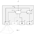
- the depicted luminaire 1 is suitable for regular lighting operation (i.e., regular illumination) as well as for emergency lighting operation (i.e., emergency illumination).
- the luminaire 1 comprises a sensor unit 11; a control unit 12; a driver unit 13; an LED load 14; and a first communication unit 15.
- the sensor unit 11 may comprise a presence and/or motion sensor, being configured to selectively provide the control unit 12 with the supply voltage 10, L of the luminaire 1 in response to a presence and/or motion sensor reading.
- the sensor unit 11 may comprise a light intensity sensor (not shown), such as a daylight sensor, being configured to selectively provide the control unit 12 with the supply voltage 10, L of the luminaire 1 in response to a light intensity sensor reading.
- a light intensity sensor such as a daylight sensor
- the sensor unit 11 may comprise a communication interface (not shown) of a lighting control bus, such as a Digital Addressable Lighting Interface (DALI, or DALI-2) bus.
- the communication interface may be configured to selectively provide the control unit 12 with the supply voltage 10, L of the luminaire 1 in response to a sensor reading indicated via the lighting control bus.
- DALI Digital Addressable Lighting Interface
- the sensor unit 11 is configured to selectively provide the control unit 12 with a supply voltage 10, L of the luminaire 1 in response to a sensor reading such as presence/motion, daylight, etc.
- the sensor unit 11 behaves like a light switch in that it switches/connects through the supply voltage 10, L of the luminaire 1 to the control unit 12 upon the sensor reading.
- the control unit 12 may comprise one of: an Application-Specific Integrated Circuit (ASIC), a field-programmable gate array (FPGA), a microcontroller ( ⁇ C), a Central Processing Unit (CPU), and the like.
- ASIC Application-Specific Integrated Circuit
- FPGA field-programmable gate array
- ⁇ C microcontroller
- CPU Central Processing Unit
- the driver unit 13 may comprise a commercially available LED driver matching the electrical requirements of the LED load 14.
- the LED load 14 may comprise at least one LED.
- the first communication unit 15 may comprise one of: a Wireless Local Area Network, WLAN, communication interface in accordance with IEEE 802.11; a Thread communication interface in accordance with IEEEE 802.15.4; a Bluetooth communication interface, a Bluetooth Low Energy, BLE, communication interface, a SubGHz communication interface preferrable in the ISM bands (e.g. 433 MHz, 868 MHz, 915 MHz), or operating at another frequency.
- the control unit 12 may further be configured to detect the absence of the zero crossings (i.e., emergency lighting operation) using the ZXD circuit 121.
- the luminaire 1 of the first aspect is capable of distinguishing regular lighting operation and emergency lighting operation once the sensor unit 11 is active.
- the rule of behavior of the control unit 12 for the emergency lighting operation may comprise one of: If the parameter 17, X corresponds to ... ... then ... ... a value of 0 , ... not driving the LED load 14 and not responding to the provided supply voltage 10, L any further ⁇ stop regular lighting operation ; ... a value between 1 and 100, ... driving the LED load 14 at a dim level corresponding to the parameter 17, X and not responding to the provided supply voltage 10, L ; 10, L ' any further ⁇ proceed to emergency lighting operation with defined dim level ; ... a value of 101 , ... driving the LED load 14 at a predefined dim level and not responding to the provided supply voltage 10, L; 10, L' any further ⁇ proceed to emergency lighting operation with pre defined dim level ; ...
- the control unit 12 is further configured to control the driver unit 13 in accordance with the rule of behavior for the emergency lighting operation and the selectively provided supply voltage 10', L'.
- the driver unit 13 is configured to drive the LED load 14.
- the control unit 12 is further configured to trigger the first communication unit 15 in response to the selectively provided supply voltage 10', L', and in particular in response to the absence of the zero crossings in the selectively provided supply voltage 10', L'.
- the first communication unit 15 is configured to send an indication of the emergency lighting operation in response to the trigger to other luminaires 1, 1'; and may further be configured to receive the indication of the emergency lighting operation from the other luminaires 1, 1'.
- the luminaire 1 of the first aspect enables
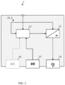
- FIG. 2 illustrates a luminaire 1' in accordance with the present disclosure.
- the luminaire 1' of FIG. 2 is suitable for regular lighting operation as well as for emergency lighting operation.
- the depicted luminaire 1' comprises a control unit 12; a driver unit 13; an LED load 14; and a first communication unit 15 as described in connection with FIG. 1 .
- the luminaire 1' of FIG. 2 lacks a sensor unit 11.
- the luminaire 1 of the second aspect is capable of distinguishing regular lighting operation and emergency lighting operation as follows: First, the control unit 12 of the luminaire 1' of FIG. 2 is configured to receive a permanently provided supply voltage 10, L.
- This permanently provided supply voltage 10, L may comprise one of: an AC voltage or a rectified AC voltage under regular lighting operation; and a DC voltage under the emergency lighting operation.
- the control unit 12 of the luminaire 1' of FIG. 2 is further configured to control the driver unit 13 in accordance with a rule of behavior (see above) for emergency lighting operation and the permanently provided supply voltage 10, L.
- the luminaire 1' of FIG. 2 may autonomously establish emergency situations by detecting an absence of the zero crossings in the permanently provided supply voltage 10, L as described above.
- the first communication unit 15 of the luminaire 1' of FIG. 2 is further configured to receive an indication of the emergency lighting operation from other luminaires 1, 1'. Accordingly, the luminaire 1' of FIG. 2 may further establish emergency situations by receiving appropriate indications from other luminaires 1, 1'.
- the driver unit 13 is configured to drive the LED load 14.
- the control unit 12 may further be configured to trigger the first communication unit 15 in response to the absence of zero crossings in the permanently provided supply voltage 10, L ; and the first communication unit 15 may further be configured to send the indication of the emergency lighting operation in response to the trigger.
- the luminaire 1, 1' may also comprise a second communication unit 16 such as an NFC interface; and the control unit 12 may further be configured to receive, via the second communication unit 16, a parameter 17, X being indicative of the rule of behavior for the emergency lighting operation.
- a parameter 17, X being indicative of the rule of behavior for the emergency lighting operation.
- the luminaire 1' of the second aspect enables
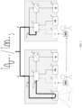
- FIG. 3 illustrates a lighting system 1, 1' in regular lighting operation.
- the lighting system 1, 1' comprises the luminaires 1 (with a sensor unit 11) and 1' (without a sensor unit 11) as explained in connection with FIGs. 1 and 2 , respectively.
- the supply voltage 10, L applied comprises one of an AC voltage or a rectified AC voltage. That is to say, the luminaires 1, 1' receive a same AC supply voltage having zero crossings.
- the sensor unit 11 of the luminaire 1 (left side of FIG. 3 ) is configured to selectively provide the control unit 12 with a supply voltage 10, L of the luminaire 1 in response to the sensor reading, such that the control unit 12 of the luminaire 1 receives the selectively provided supply voltage 10', L '.
- control unit 12 of the luminaire 1' receives a permanently provided supply voltage 10, L.
- control units 12 of both luminaires 1, 1' are further configured to control their driver units 13 in accordance with a respective rule of behavior (see above) for emergency lighting operation and the respective provided supply voltage 10, L, 10, L '.
- both control units 12 will detect a presence of zero crossings and therefore not control their driver units 13 in accordance with an emergency lighting operation.
- FIG. 3 also indicates operating staff proceeding from luminaire 1 to luminaire 1' for a respective configuration as an emergency luminaire (or regular luminaire) by holding an NFC tag to its NFC interface 16, if any.
- FIG. 4 illustrates a lighting system 1, 1' in emergency lighting operation.
- the lighting system 1, 1' of FIG. 4 corresponds to the lighting system of FIG. 3 .
- the supply voltage 10, L applied comprises a DC voltage. Accordingly, the luminaires 1, 1' receive a DC supply voltage wherein zero crossings are absent.
- the sensor unit 11 of the luminaire 1 (left side of FIG. 4 ) is configured to selectively provide the control unit 12 with a supply voltage 10, L of the luminaire 1 in response to the sensor reading, such that the control unit 12 of the luminaire 1 receives the selectively provided supply voltage 10', L '.
- the control unit 12 of the luminaire 1' receives a permanently provided supply voltage 10, L.
- control units 12 of both luminaires 1, 1' are further configured to control their driver units 13 in accordance with a respective rule of behavior (see above) for emergency lighting operation and the respective provided supply voltage 10, L, 10, L '.
- both control units 12 will detect an absence of zero crossings and therefore control their driver units 13 in accordance with an emergency lighting operation.
- the control unit 12 of the luminaire 1 (left side of FIG. 4 ) further triggers its first communication unit 15 in response to the absence of the zero crossings in the selectively provided supply voltage 10', L'; and the first communication unit 15 of the luminaire 1 (left side of FIG. 4 ) further sends an indication of the emergency lighting operation in response to the trigger.
- the first communication unit 15 of the luminaire 1' receives the indication of the emergency lighting operation from the other luminaire 1.
- the luminaire 1' may autonomously establish emergency situations by detecting the absence of the zero crossings in the permanently provided supply voltage 10, L as described above, and may further establish emergency situations by receiving appropriate indications from the sensor-based luminaire 1.
- an arbitrary luminaire 1, 1' of a lighting system may respond to an emergency situation even without any a zero crossing detection.
- FIG. 5 illustrates a state diagram of the control unit 12 of the luminaire 1, 1'.
- the stripped-down state diagram includes two states S 1 (regular lighting operation, i.e., no emergency illumination) and S 2 (emergency lighting operation, i.e., emergency illumination), respectively.
- the control unit 12 may be configured to detect the corresponding presence of zero crossings in the provided supply voltage 10, L, 10, L ' using its zero crossing detection, ZXD, circuit 121 (not shown, see FIG. 6 below), in particular upon a completion of a zero crossing countdown being set upon an emergence of the emergency lighting operation.
- the zero crossing countdown may be started from a value of 1 for immediate detection of the presence of zero crossings.
- the zero crossing counter is decremented every time a zero crossing is detected.
- the regular detection/presence of zero crossings is indicated by the non-lapse of a zero crossing timeout period in excess of a reciprocal value of a mains frequency. In other words, as long as the appropriate zero crossing timeout period doesn't lapse, regular lighting operation applies.
- a transition from regular lighting operation to emergency lighting operation is shown on the right side of FIG. 5 .
- the control unit 12 may be configured to detect the corresponding absence of the zero crossings in the provided supply voltage 10, L, 10, L ' using the ZXD circuit 121 upon a lapse of the zero crossing timeout period in excess of a reciprocal value of a mains frequency.
- FIG. 6 illustrates the ZXD circuit 121 of the control unit 12 of the luminaire 1, 1'.
- An electrically connected zero-crossing detection may include a ZXD circuit 121 within the control circuit 12 preceded by a series resistor.
- the electrically isolated zero-crossing detection indicated in FIG. 6 may include an arbitrary General Purpose Input/Output (GPIO) port the control circuit 12 preceded by a low-pass circuit, an opto-coupler, and an optional rectifier bridge.
- GPIO General Purpose Input/Output
- the low-pass circuit includes a resistor and a capacitor in series. An appropriate dimensioning of the low-pass circuit achieves an incomplete smoothing of the resulting ZCD signal so that zero crossings may still be detected.
- FIG. 7 illustrates a flow diagram of a method 2 in accordance with the present disclosure of operating the luminaire 1.
- the method 2 is suitable for operating the luminaire 1 for emergency lighting operation of FIG. 1 .
- the method 2 comprises a step of selectively providing 21 a control unit 12 of the luminaire 1 with a supply voltage 10, L of the luminaire 1 in response to a sensor reading.
- the method 2 further comprises controlling 22 a driver unit 13 of the luminaire 1 in accordance with a rule of behavior for the emergency lighting operation and the selectively provided supply voltage 10 ' , L'.
- the method 2 further comprises driving 23 an LED load 14 of the luminaire 1.
- the method 2 further comprises triggering 24 a first communication unit 15 of the luminaire 1 in response to an absence of zero crossings in the selectively provided supply voltage 10', L '; and sending 25 an indication of the emergency lighting operation in response to the trigger.
- FIG. 8 illustrates a flow diagram of a method 2' in accordance with the present disclosure of operating the luminaire 1'.
- the method 2' is suitable for operating the luminaire 1' for emergency lighting operation of FIG. 2 .
- the method 2' comprises receiving 25' an indication of the emergency lighting operation.
- this may be the indication of the emergency lighting operation sent by a luminaire 1 of the first aspect (i.e., including a sensor unit).
- the method 2' further comprises controlling 22' a driver unit 13 of the luminaire 1 in accordance with a rule of behavior for the emergency lighting operation and a permanently provided supply voltage 10, L of the luminaire 1; and driving 23 an LED load 14 of the luminaire 1.
Landscapes
- Circuit Arrangement For Electric Light Sources In General (AREA)
Abstract
Disclosed is a luminaire (1) for emergency lighting operation. The luminaire (1) comprises a sensor unit (11); a control unit (12); a driver unit (13); an LED load (14); and a first communication unit (15). The sensor unit (11) is configured to selectively provide the control unit (12) with a supply voltage (10, L) of the luminaire (1) in response to a sensor reading. The control unit (12) is configured to control the driver unit (13) in accordance with a rule of behavior for the emergency lighting operation and the selectively provided supply voltage (10', L'); and to trigger the first communication unit (15) in response to an absence of zero crossings in the selectively provided supply voltage (10', L'). The driver unit (13) is configured to drive the LED load (14); and the first communication unit (15) is configured to send an indication of the emergency lighting operation in response to the trigger. Such luminaires are cost-efficient and may be configured for emergency lighting operation on-demand.
Description
- The present disclosure relates to lighting technology, and in particular to luminaires for emergency lighting operation.
- Basic lighting systems may require the deployment of cost-conscious system components. Luminaires of such lighting systems may for cost reasons not be arranged to detect an emergency situation and to perform a corresponding emergency lighting operation, let alone in connection with some kind of configurability.
- In view of the above-mentioned drawbacks and limitations, the present disclosure aims to improve the lighting systems of the background art. An objective is to provide cost-efficient luminaires that can be configured for emergency lighting operation on-demand.
- The objective is achieved by the embodiments as defined by the appended independent claims. Preferred embodiments are set forth in the dependent claims and in the following description and drawings.
- A first aspect of the present disclosure relates to a luminaire for emergency lighting operation. The luminaire comprises a sensor unit; a control unit; a driver unit; an LED load; and a first communication unit. The sensor unit is configured to selectively provide the control unit with a supply voltage of the luminaire in response to a sensor reading. The control unit is configured to control the driver unit in accordance with a rule of behavior for the emergency lighting operation and the selectively provided supply voltage; and to trigger the first communication unit in response to an absence of zero crossings in the selectively provided supply voltage. The driver unit is configured to drive the LED load; and the first communication unit is configured to send an indication of the emergency lighting operation in response to the trigger.
- The first communication unit may further be configured to receive the indication of the emergency lighting operation.
- A second aspect of the present disclosure relates to a luminaire for emergency lighting operation. The luminaire comprises a control unit; a driver unit; an LED load; and a first communication unit. The first communication unit is configured to receive an indication of the emergency lighting operation. The control unit is configured to control the driver unit in accordance with a rule of behavior for emergency lighting operation and a permanently provided supply voltage of the luminaire. The driver unit is configured to drive the LED load.
- The control unit may further be configured to trigger the first communication unit in response to an absence of zero crossings in the permanently provided supply voltage; and the first communication unit may further be configured to send the indication of the emergency lighting operation in response to the trigger.
- The supply voltage of the luminaire may comprise one of: an alternating current, AC, voltage or a rectified AC voltage under regular lighting operation; and a direct current, DC, voltage under the emergency lighting operation.
- The control unit may further comprise a zero crossing detection, ZXD, circuit; and the control unit may further be configured to detect the absence of the zero crossings using the ZXD circuit upon a lapse of a zero crossing timeout period in excess of a reciprocal value of a mains frequency.
- The control unit may further be configured to detect a presence of the zero crossings using the ZXD circuit upon a completion of a zero crossing countdown being set upon an emergence of the emergency lighting operation.
- The first communication unit may comprise one of: a Wireless Local Area Network, WLAN, communication interface in accordance with IEEE 802.11; a Thread communication interface in accordance with IEEEE 802.15.4; a Bluetooth communication interface, a Bluetooth Low Energy, BLE, communication interface, a SubGHz communication interface preferable in the ISM bands (e.g. 433 MHz, 868 MHz, 915 MHz), or operating at another frequency.
- The sensor unit may comprise one of: a presence and/or motion sensor, being configured to selectively provide the control unit with the supply voltage of the luminaire in response to a presence and/or motion sensor reading; a light intensity sensor, being configured to selectively provide the control unit with the supply voltage of the luminaire in response to a light intensity sensor reading; and a communication interface of a lighting control bus, being configured to selectively provide the control unit with the supply voltage of the luminaire in response to a sensor reading via the lighting control bus.
- The lighting control bus may comprise a Digital Addressable Lighting Interface, DALI, bus.
- The luminaire may further comprise a second communication unit; and the control unit may further be configured to receive, via the second communication unit, a parameter being indicative of the rule of behavior for the emergency lighting operation.
- The second communication unit may comprise a Near Field Communication, NFC, interface.
- The rule of behavior for the emergency lighting operation may comprise one of: not driving the LED load and not responding to the provided supply voltage any further, if the parameter corresponds to a value of 0; driving the LED load at a dim level corresponding to the parameter and not responding to the provided supply voltage any further, if the parameter corresponds to a value between 1 and 100; driving the LED load at a predefined dim level and not responding to the provided supply voltage any further, if the parameter corresponds to a value of 101; and driving the LED load at a dim level corresponding to regular operating conditions in response to the provided supply voltage, if the parameter corresponds to a value of 255.
- A third aspect of the present disclosure relates to a method of operating a luminaire for emergency lighting operation. The method comprises selectively providing a control unit of the luminaire with a supply voltage of the luminaire in response to a sensor reading. The method further comprises controlling a driver unit of the luminaire in accordance with a rule of behavior for the emergency lighting operation and the selectively provided supply voltage. The method further comprises driving an LED load of the luminaire. The method further comprises triggering a first communication unit of the luminaire in response to an absence of zero crossings in the selectively provided supply voltage; and sending an indication of the emergency lighting operation in response to the trigger.
- A fourth aspect of the present disclosure relates to a method of operating a luminaire for emergency lighting operation. The method comprises receiving an indication of the emergency lighting operation. The method further comprises controlling a driver unit of the luminaire in accordance with a rule of behavior for the emergency lighting operation and a permanently provided supply voltage of the luminaire; and driving an LED load of the luminaire.
- The present disclosure provides cost-efficient luminaires using simple components, such as presence/movement sensors behaving like light switches. The luminaires are on-demand configurable for emergency lighting operation, detect emergency situations via voltage supply or indications received from other luminaires, and perform the emergency lighting operation in accordance with said configuration.
- The technical effects and advantages described above in relation with the luminaires equally apply to the methods of operating the same having corresponding features.
- The above-described aspects and implementations will now be explained with reference to the accompanying drawings, in which the same or similar reference numerals designate the same or similar elements.
- The features of these aspects and implementations may be combined with each other unless specifically stated otherwise.
- The drawings are to be regarded as being schematic representations, and elements illustrated in the drawings are not necessarily shown to scale. Rather, the various elements are represented such that their function and general purpose become apparent to those skilled in the art.
-
FIG. 1 illustrates a luminaire in accordance with the present disclosure; -
FIG. 2 illustrates a luminaire in accordance with the present disclosure; -
FIG. 3 illustrates a lighting system in regular lighting operation; -
FIG. 4 illustrates a lighting system in emergency lighting operation; -
FIG. 5 illustrates a state diagram of the control unit of the luminaire; -
FIG. 6 illustrates the ZXD circuit of the control unit of the luminaire; -
FIG. 7 illustrates a flow diagram of a method in accordance with the present disclosure of operating the luminaire; and -
FIG. 8 illustrates a flow diagram of a method in accordance with the present disclosure of operating the luminaire. -
FIG. 1 illustrates aluminaire 1 in accordance with the present disclosure. - The depicted
luminaire 1 is suitable for regular lighting operation (i.e., regular illumination) as well as for emergency lighting operation (i.e., emergency illumination). - The
luminaire 1 comprises asensor unit 11; acontrol unit 12; adriver unit 13; anLED load 14; and afirst communication unit 15. - In accordance with
FIG. 1 , thesensor unit 11 may comprise a presence and/or motion sensor, being configured to selectively provide thecontrol unit 12 with thesupply voltage 10, L of theluminaire 1 in response to a presence and/or motion sensor reading. - Alternatively, the
sensor unit 11 may comprise a light intensity sensor (not shown), such as a daylight sensor, being configured to selectively provide thecontrol unit 12 with thesupply voltage 10, L of theluminaire 1 in response to a light intensity sensor reading. - Alternatively, the
sensor unit 11 may comprise a communication interface (not shown) of a lighting control bus, such as a Digital Addressable Lighting Interface (DALI, or DALI-2) bus. The communication interface may be configured to selectively provide thecontrol unit 12 with thesupply voltage 10, L of theluminaire 1 in response to a sensor reading indicated via the lighting control bus. - The
sensor unit 11 is configured to selectively provide thecontrol unit 12 with asupply voltage 10, L of theluminaire 1 in response to a sensor reading such as presence/motion, daylight, etc. In other words, thesensor unit 11 behaves like a light switch in that it switches/connects through thesupply voltage 10, L of theluminaire 1 to thecontrol unit 12 upon the sensor reading. - The
control unit 12 may comprise one of: an Application-Specific Integrated Circuit (ASIC), a field-programmable gate array (FPGA), a microcontroller (µC), a Central Processing Unit (CPU), and the like. - The
driver unit 13 may comprise a commercially available LED driver matching the electrical requirements of theLED load 14. - The
LED load 14 may comprise at least one LED. - The
first communication unit 15 may comprise one of: a Wireless Local Area Network, WLAN, communication interface in accordance with IEEE 802.11; a Thread communication interface in accordance with IEEEE 802.15.4; a Bluetooth communication interface, a Bluetooth Low Energy, BLE, communication interface, a SubGHz communication interface preferrable in the ISM bands (e.g. 433 MHz, 868 MHz, 915 MHz), or operating at another frequency. - The
supply voltage 10, L of theluminaire 1, which may be applied at a port suggested on top ofFIG. 1 , may comprise one of: an alternating current (AC) voltage or a rectified AC voltage under regular lighting operation; and a direct current (DC) voltage under the emergency lighting operation. That is to say, theluminaire 1 regularly receives an AC supply voltage having zero crossings, whereas in emergency situations theluminaire 1 receives a DC supply voltage from a central emergency power supply such as a battery. - The
control unit 12 may be configured to detect a presence of zero crossings (i.e., regular lighting operation) using a zero crossing detection, ZXD, circuit 121 (not shown, seeFIG. 6 below). - In particular, the presence of zero crossings may be detected upon a completion of a zero crossing countdown being set upon an emergence of the emergency lighting operation. For example, the zero crossing countdown may be started from a value of 1 for immediate detection of the presence of zero crossings, whereas higher start values may prevent a premature detection of the presence of zero crossings.
- The
control unit 12 may further be configured to detect the absence of the zero crossings (i.e., emergency lighting operation) using theZXD circuit 121. - In particular, the absence of zero crossings may be detected upon a lapse of a zero crossing timeout period in excess of a reciprocal value of a mains frequency. For example, a mains frequency of ƒ = 50 or 60 Hz implies a zero crossing every 1/f = 10 ms (8, 3 ms). Thus, depending on the applicable mains frequency, a zero crossing timeout period in excess of 10 ms (8, 3 ms) should be used, and the corresponding timer should be (re-)set to this zero crossing timeout period each time a zero crossing is detected.
- Accordingly, the
luminaire 1 of the first aspect is capable of distinguishing regular lighting operation and emergency lighting operation once thesensor unit 11 is active. - The
luminaire 1 may further comprise asecond communication unit 16, such as a Near Field Communication (NFC) interface; and may further be configured to receive, via thesecond communication unit 16, a parameter 17, X being indicative of a rule of behavior for the emergency lighting operation. - For example, the rule of behavior of the
control unit 12 for the emergency lighting operation may comprise one of:If the parameter 17, X corresponds to ... ... then ... ... a value of 0, ... not driving the LED load 14 and not responding to the providedsupply voltage 10, L any further ⇒ stop regular lighting operation ;... a value between 1 and 100, ... driving the LED load 14 at a dim level corresponding to the parameter 17, X and not responding to the providedsupply voltage 10, L; 10, L' any further ⇒ proceed to emergency lighting operation with defined dim level ;... a value of 101, ... driving the LED load 14 at a predefined dim level and not responding to the providedsupply voltage 10, L; 10, L' any further ⇒ proceed to emergency lighting operation with predefined dim level ; ... a value between 102 and 254, ... (reserved) ... a value of 255, ... driving the LED load 14 at a dim level corresponding to regular operating conditions in response to the providedsupply voltage 10, L; 10, L ' ⇒ continue regular lighting operation. - Accordingly, an
arbitrary luminaire 1, 1' may be configured as an emergency luminaire (or regular luminaire) by holding an NFC tag to it.Other luminaires 1, 1' may be configured to be switched off in emergency situations so as to preserve the central emergency DC supply. - The
control unit 12 is further configured to control thedriver unit 13 in accordance with the rule of behavior for the emergency lighting operation and the selectively provided supply voltage 10', L'. - Evidently, the
driver unit 13 is configured to drive theLED load 14. - The
control unit 12 is further configured to trigger thefirst communication unit 15 in response to the selectively provided supply voltage 10', L', and in particular in response to the absence of the zero crossings in the selectively provided supply voltage 10', L'. - The
first communication unit 15 is configured to send an indication of the emergency lighting operation in response to the trigger toother luminaires 1, 1'; and may further be configured to receive the indication of the emergency lighting operation from theother luminaires 1, 1'. - In summary, the
luminaire 1 of the first aspect enables - recognizing emergency situations by detecting, upon a sensor reading, a lack of zero crossings in a centralized emergency DC voltage supply (or by receiving an indication of such situations), and
- responding to the recognized emergency situations in accordance with an on-demand configuration.
-
FIG. 2 illustrates a luminaire 1' in accordance with the present disclosure. - Like the
luminaire 1 ofFIG. 1 , the luminaire 1' ofFIG. 2 is suitable for regular lighting operation as well as for emergency lighting operation. - The depicted luminaire 1' comprises a
control unit 12; adriver unit 13; anLED load 14; and afirst communication unit 15 as described in connection withFIG. 1 . - However, unlike the
luminaire 1 ofFIG. 1 , the luminaire 1' ofFIG. 2 lacks asensor unit 11. - Despite the lack of a
sensor unit 11, theluminaire 1 of the second aspect is capable of distinguishing regular lighting operation and emergency lighting operation as follows:
First, thecontrol unit 12 of the luminaire 1' ofFIG. 2 is configured to receive a permanently providedsupply voltage 10, L. - This permanently provided
supply voltage 10, L may comprise one of: an AC voltage or a rectified AC voltage under regular lighting operation; and a DC voltage under the emergency lighting operation. - The
control unit 12 of the luminaire 1' ofFIG. 2 is further configured to control thedriver unit 13 in accordance with a rule of behavior (see above) for emergency lighting operation and the permanently providedsupply voltage 10, L. In other words, the luminaire 1' ofFIG. 2 may autonomously establish emergency situations by detecting an absence of the zero crossings in the permanently providedsupply voltage 10, L as described above. - Second, the
first communication unit 15 of the luminaire 1' ofFIG. 2 is further configured to receive an indication of the emergency lighting operation fromother luminaires 1, 1'. Accordingly, the luminaire 1' ofFIG. 2 may further establish emergency situations by receiving appropriate indications fromother luminaires 1, 1'. - As before, the
driver unit 13 is configured to drive theLED load 14. - The
control unit 12 may further be configured to trigger thefirst communication unit 15 in response to the absence of zero crossings in the permanently providedsupply voltage 10, L; and thefirst communication unit 15 may further be configured to send the indication of the emergency lighting operation in response to the trigger. - The
luminaire 1, 1' may also comprise asecond communication unit 16 such as an NFC interface; and thecontrol unit 12 may further be configured to receive, via thesecond communication unit 16, a parameter 17, X being indicative of the rule of behavior for the emergency lighting operation. - In summary, the luminaire 1' of the second aspect enables
- recognizing emergency situations by detecting a lack of zero crossings in a centralized emergency DC voltage supply (or by receiving an indication of such situations), and
- responding to the recognized emergency situations in accordance with an on-demand configuration.
-
FIG. 3 illustrates alighting system 1, 1' in regular lighting operation. - In this example, the
lighting system 1, 1' comprises the luminaires 1 (with a sensor unit 11) and 1' (without a sensor unit 11) as explained in connection withFIGs. 1 and2 , respectively. - Under regular lighting operation, the
supply voltage 10, L applied comprises one of an AC voltage or a rectified AC voltage. That is to say, theluminaires 1, 1' receive a same AC supply voltage having zero crossings. - Assuming a sensor reading such as a presence/motion, daylight, and the like, the
sensor unit 11 of the luminaire 1 (left side ofFIG. 3 ) is configured to selectively provide thecontrol unit 12 with asupply voltage 10, L of theluminaire 1 in response to the sensor reading, such that thecontrol unit 12 of theluminaire 1 receives the selectively provided supply voltage 10', L '. - By contrast, the
control unit 12 of the luminaire 1' (right side ofFIG. 3 ) receives a permanently providedsupply voltage 10, L. - The
control units 12 of bothluminaires 1, 1' are further configured to control theirdriver units 13 in accordance with a respective rule of behavior (see above) for emergency lighting operation and the respective providedsupply voltage 10, L, 10, L '. - Under regular lighting operation, both
control units 12 will detect a presence of zero crossings and therefore not control theirdriver units 13 in accordance with an emergency lighting operation. -
FIG. 3 also indicates operating staff proceeding fromluminaire 1 to luminaire 1' for a respective configuration as an emergency luminaire (or regular luminaire) by holding an NFC tag to itsNFC interface 16, if any. -
FIG. 4 illustrates alighting system 1, 1' in emergency lighting operation. - The
lighting system 1, 1' ofFIG. 4 corresponds to the lighting system ofFIG. 3 . - However, under emergency lighting operation, the
supply voltage 10, L applied comprises a DC voltage. Accordingly, theluminaires 1, 1' receive a DC supply voltage wherein zero crossings are absent. - Assuming a sensor reading such as a presence/motion, daylight, and the like, the
sensor unit 11 of the luminaire 1 (left side ofFIG. 4 ) is configured to selectively provide thecontrol unit 12 with asupply voltage 10, L of theluminaire 1 in response to the sensor reading, such that thecontrol unit 12 of theluminaire 1 receives the selectively provided supply voltage 10', L '. - The
control unit 12 of the luminaire 1' (right side ofFIG. 4 ) receives a permanently providedsupply voltage 10, L. - The
control units 12 of bothluminaires 1, 1' are further configured to control theirdriver units 13 in accordance with a respective rule of behavior (see above) for emergency lighting operation and the respective providedsupply voltage 10, L, 10, L '. - Under emergency lighting operation, both
control units 12 will detect an absence of zero crossings and therefore control theirdriver units 13 in accordance with an emergency lighting operation. - The
control unit 12 of the luminaire 1 (left side ofFIG. 4 ) further triggers itsfirst communication unit 15 in response to the absence of the zero crossings in the selectively provided supply voltage 10', L'; and thefirst communication unit 15 of the luminaire 1 (left side ofFIG. 4 ) further sends an indication of the emergency lighting operation in response to the trigger. - In turn, the
first communication unit 15 of the luminaire 1' (right side ofFIG. 4 ) receives the indication of the emergency lighting operation from theother luminaire 1. - Accordingly, the luminaire 1' (right side of
FIG. 4 ) may autonomously establish emergency situations by detecting the absence of the zero crossings in the permanently providedsupply voltage 10, L as described above, and may further establish emergency situations by receiving appropriate indications from the sensor-basedluminaire 1. Thus, anarbitrary luminaire 1, 1' of a lighting system may respond to an emergency situation even without any a zero crossing detection. -
FIG. 5 illustrates a state diagram of thecontrol unit 12 of theluminaire 1, 1'. - The stripped-down state diagram includes two states S1 (regular lighting operation, i.e., no emergency illumination) and S2 (emergency lighting operation, i.e., emergency illumination), respectively.
- On the left side of
FIG. 5 , a transition from emergency lighting operation to regular lighting operation is shown. - Note the sine shapes of the provided
supply voltage 10, L, 10, L ' in the diagrams on the left ofFIG. 5 . - The
control unit 12 may be configured to detect the corresponding presence of zero crossings in the providedsupply voltage 10, L, 10, L' using its zero crossing detection, ZXD, circuit 121 (not shown, seeFIG. 6 below), in particular upon a completion of a zero crossing countdown being set upon an emergence of the emergency lighting operation. For example, the zero crossing countdown may be started from a value of 1 for immediate detection of the presence of zero crossings. The zero crossing counter is decremented every time a zero crossing is detected. - The regular detection/presence of zero crossings is indicated by the non-lapse of a zero crossing timeout period in excess of a reciprocal value of a mains frequency. In other words, as long as the appropriate zero crossing timeout period doesn't lapse, regular lighting operation applies.
- A transition from regular lighting operation to emergency lighting operation is shown on the right side of
FIG. 5 . - Note the discontinuation of the sine-shaped provided
supply voltage 10, L, 10, L ' in the diagram on the right ofFIG. 5 and the subsequent transition to a providedDC supply voltage 10, L, 10, L' upon reception from the central emergency power supply. - The
control unit 12 may be configured to detect the corresponding absence of the zero crossings in the providedsupply voltage 10, L, 10, L ' using theZXD circuit 121 upon a lapse of the zero crossing timeout period in excess of a reciprocal value of a mains frequency. - In other words, as long as the zero crossing timeout period lapses, emergency lighting operation (state S2 ) applies. As soon as zero crossings emerge and the zero crossing timeout period fails to lapse, a return to the regular lighting operation (state S1 ) is appropriate.
-
FIG. 6 illustrates theZXD circuit 121 of thecontrol unit 12 of theluminaire 1, 1'. - An electrically connected zero-crossing detection (not shown) may include a
ZXD circuit 121 within thecontrol circuit 12 preceded by a series resistor. - The electrically isolated zero-crossing detection indicated in
FIG. 6 may include an arbitrary General Purpose Input/Output (GPIO) port thecontrol circuit 12 preceded by a low-pass circuit, an opto-coupler, and an optional rectifier bridge. - The low-pass circuit includes a resistor and a capacitor in series. An appropriate dimensioning of the low-pass circuit achieves an incomplete smoothing of the resulting ZCD signal so that zero crossings may still be detected.
-
FIG. 7 illustrates a flow diagram of amethod 2 in accordance with the present disclosure of operating theluminaire 1. - The
method 2 is suitable for operating theluminaire 1 for emergency lighting operation ofFIG. 1 . - The
method 2 comprises a step of selectively providing 21 acontrol unit 12 of theluminaire 1 with asupply voltage 10, L of theluminaire 1 in response to a sensor reading. - The
method 2 further comprises controlling 22 adriver unit 13 of theluminaire 1 in accordance with a rule of behavior for the emergency lighting operation and the selectively provided supply voltage 10',L'. - The
method 2 further comprises driving 23 anLED load 14 of theluminaire 1. - The
method 2 further comprises triggering 24 afirst communication unit 15 of theluminaire 1 in response to an absence of zero crossings in the selectively provided supply voltage 10', L'; and sending 25 an indication of the emergency lighting operation in response to the trigger. -
FIG. 8 illustrates a flow diagram of a method 2' in accordance with the present disclosure of operating the luminaire 1'. - The method 2' is suitable for operating the luminaire 1' for emergency lighting operation of
FIG. 2 . - The method 2' comprises receiving 25' an indication of the emergency lighting operation. In particular, this may be the indication of the emergency lighting operation sent by a
luminaire 1 of the first aspect (i.e., including a sensor unit). - The method 2' further comprises controlling 22' a
driver unit 13 of theluminaire 1 in accordance with a rule of behavior for the emergency lighting operation and a permanently providedsupply voltage 10, L of theluminaire 1; and driving 23 anLED load 14 of theluminaire 1.
Claims (15)
- A luminaire (1) for emergency lighting operation, comprisinga sensor unit (11); a control unit (12); a driver unit (13); an LED load (14); and a first communication unit (15);the sensor unit (11) being configured to- selectively provide the control unit (12) with a supply voltage (10, L) of the luminaire (1) in response to a sensor reading;the control unit (12) being configured to- control the driver unit (13) in accordance with a rule of behavior for the emergency lighting operation and the selectively provided supply voltage (10', L'); and- trigger the first communication unit (15) in response to an absence of zero crossings in the selectively provided supply voltage (10', L');the driver unit (13) being configured to- drive the LED load (14); andthe first communication unit (15) being configured to- send an indication of the emergency lighting operation in response to the trigger.
- The luminaire (1) of claim 1,
the first communication unit (15) further being configured to- receive the indication of the emergency lighting operation. - A luminaire (1') for emergency lighting operation, comprisinga control unit (12); a driver unit (13); an LED load (14); and a first communication unit (15);the first communication unit (15) being configured to- receive an indication of the emergency lighting operation;the control unit (12) being configured to- control the driver unit (13) in accordance with a rule of behavior for emergency lighting operation and a permanently provided supply voltage (10, L) of the luminaire (1'); andthe driver unit (13) being configured to- drive the LED load (14).
- The luminaire (1') of claim 3,the control unit (12) further being configured to- trigger the first communication unit (15) in response to an absence of zero crossings in the permanently provided supply voltage (10, L);the first communication unit (15) further being configured to- send the indication of the emergency lighting operation in response to the trigger.
- The luminaire (1, 1') of any one of the preceding claims,
the supply voltage (10, L) of the luminaire (1, 1') comprising one of:- an alternating current, AC, voltage or a rectified AC voltage under regular lighting operation; and- a direct current, DC, voltage under the emergency lighting operation. - The luminaire (1, 1') of any one of the preceding claims,the control unit (12) further comprising
a zero crossing detection, ZXD, circuit (121);the control unit (12) further being configured to- detect the absence of the zero crossings using the ZXD circuit (121) upon a lapse of a zero crossing timeout period in excess of a reciprocal value of a mains frequency. - The luminaire (1, 1') of claim 6,
the control unit (12) further being configured to- detect a presence of the zero crossings using the ZXD circuit (121) upon a completion of a zero crossing countdown being set upon an emergence of the emergency lighting operation. - The luminaire (1, 1') of any one of the preceding claims,
the first communication unit (15) comprising one of:- a Wireless Local Area Network, WLAN, communication interface in accordance with IEEE 802.11;- a Thread communication interface in accordance with IEEEE 802.15.4;- a Bluetooth communication interface,- a Bluetooth Low Energy, BLE, communication interface,- a SubGHz communication interface preferrable in the ISM bands (e.g. 433 MHz, 868 MHz, 915 MHz), or operating at another frequency. - The luminaire (1, 1') of any one of the preceding claims,
the sensor unit (11) comprising one of:a presence and/or motion sensor, being configured to- selectively provide the control unit (12) with the supply voltage (10, L) of the luminaire (1) in response to a presence and/or motion sensor reading;a light intensity sensor, being configured to- selectively provide the control unit (12) with the supply voltage (10, L) of the luminaire (1) in response to a light intensity sensor reading; anda communication interface of a lighting control bus, being configured to- selectively provide the control unit (12) with the supply voltage (10, L) of the luminaire (1) in response to a sensor reading via the lighting control bus. - The luminaire (1, 1') of claim 9,
the lighting control bus comprising a Digital Addressable Lighting Interface, DALI, bus. - The luminaire (1, 1') of any one of the preceding claims, further comprisinga second communication unit (16);the control unit (12) further being configured to- receive, via the second communication unit (16), a parameter (17, X) being indicative of the rule of behavior for the emergency lighting operation.
- The luminaire (1, 1') of claim 11,
the second communication unit (16) comprising
a Near Field Communication, NFC, interface. - The luminaire (1, 1') of claim 11 or claim 12,
the rule of behavior for the emergency lighting operation comprising one of:- not driving the LED load (14) and not responding to the provided supply voltage (10, L) any further, if the parameter (17, X) corresponds to a value of 0;- driving the LED load (14) at a dim level corresponding to the parameter (17, X) and not responding to the provided supply voltage (10, L; 10, L ') any further, if the parameter (17, X) corresponds to a value between 1 and 100;- driving the LED load (14) at a predefined dim level and not responding to the provided supply voltage (10, L; 10, L') any further, if the parameter (17, X) corresponds to a value of 101; and- driving the LED load (14) at a dim level corresponding to regular operating conditions in response to the provided supply voltage (10, L; 10, L '), if the parameter (17, X) corresponds to a value of 255. - A method (2) of operating a luminaire (1) for emergency lighting operation, the method (2) comprising- selectively providing (21) a control unit (12) of the luminaire (1) with a supply voltage (10, L) of the luminaire (1) in response to a sensor reading;- controlling (22) a driver unit (13) of the luminaire (1) in accordance with a rule of behavior for the emergency lighting operation and the selectively provided supply voltage (10', L');- driving (23) an LED load (14) of the luminaire (1); and- triggering (24) a first communication unit (15) of the luminaire (1) in response to an absence of zero crossings in the selectively provided supply voltage (10', L');- sending (25) an indication of the emergency lighting operation in response to the trigger.
- A method (2') of operating a luminaire (1') for emergency lighting operation, the method (2') comprising- receiving (25') an indication of the emergency lighting operation;- controlling (22') a driver unit (13) of the luminaire (1) in accordance with a rule of behavior for the emergency lighting operation and a permanently provided supply voltage (10, L) of the luminaire (1); and- driving (23) an LED load (14) of the luminaire (1).
Priority Applications (2)
| Application Number | Priority Date | Filing Date | Title |
|---|---|---|---|
| EP23163915.4A EP4436319A1 (en) | 2023-03-24 | 2023-03-24 | Luminaires for emergency lighting operation and methods of operating the same |
| PCT/EP2024/055790 WO2024199916A1 (en) | 2023-03-24 | 2024-03-06 | Luminaires for emergency lighting operation and methods of operating the same |
Applications Claiming Priority (1)
| Application Number | Priority Date | Filing Date | Title |
|---|---|---|---|
| EP23163915.4A EP4436319A1 (en) | 2023-03-24 | 2023-03-24 | Luminaires for emergency lighting operation and methods of operating the same |
Publications (1)
| Publication Number | Publication Date |
|---|---|
| EP4436319A1 true EP4436319A1 (en) | 2024-09-25 |
Family
ID=85726465
Family Applications (1)
| Application Number | Title | Priority Date | Filing Date |
|---|---|---|---|
| EP23163915.4A Pending EP4436319A1 (en) | 2023-03-24 | 2023-03-24 | Luminaires for emergency lighting operation and methods of operating the same |
Country Status (2)
| Country | Link |
|---|---|
| EP (1) | EP4436319A1 (en) |
| WO (1) | WO2024199916A1 (en) |
Families Citing this family (1)
| Publication number | Priority date | Publication date | Assignee | Title |
|---|---|---|---|---|
| EP4352852A1 (en) * | 2021-06-08 | 2024-04-17 | Appleton Grp LLC | Hazardous area lighting with emergency power back up and wireless communications |
Citations (3)
| Publication number | Priority date | Publication date | Assignee | Title |
|---|---|---|---|---|
| US20090072970A1 (en) * | 2007-09-19 | 2009-03-19 | Barton Robert A | Safety system and method for conventional lighting fixtures |
| US20150120000A1 (en) * | 2013-03-15 | 2015-04-30 | Smartbotics Inc. | Adaptive home and commercial automation devices, methods and systems based on the proximity of controlling elements |
| US20190261493A1 (en) * | 2018-02-17 | 2019-08-22 | Lutron Technology Company Llc | Lighting Control System with Emergency Mode |
-
2023
- 2023-03-24 EP EP23163915.4A patent/EP4436319A1/en active Pending
-
2024
- 2024-03-06 WO PCT/EP2024/055790 patent/WO2024199916A1/en not_active Ceased
Patent Citations (3)
| Publication number | Priority date | Publication date | Assignee | Title |
|---|---|---|---|---|
| US20090072970A1 (en) * | 2007-09-19 | 2009-03-19 | Barton Robert A | Safety system and method for conventional lighting fixtures |
| US20150120000A1 (en) * | 2013-03-15 | 2015-04-30 | Smartbotics Inc. | Adaptive home and commercial automation devices, methods and systems based on the proximity of controlling elements |
| US20190261493A1 (en) * | 2018-02-17 | 2019-08-22 | Lutron Technology Company Llc | Lighting Control System with Emergency Mode |
Also Published As
| Publication number | Publication date |
|---|---|
| WO2024199916A1 (en) | 2024-10-03 |
Similar Documents
| Publication | Publication Date | Title |
|---|---|---|
| JP4581646B2 (en) | Light emitting diode lighting device | |
| CN212876160U (en) | Infrared human body induction lighting drive control system and corridor lighting lamp | |
| US5019747A (en) | Illumination control apparatus | |
| JP2003519895A (en) | Apparatus for controlling operating means of at least one electric lighting means and method for controlling operating means of at least one electric lighting means | |
| US20200059997A1 (en) | Operating device having a test switch and status indicator | |
| JP2017503318A (en) | Dimmer system and dimming method | |
| WO2024199916A1 (en) | Luminaires for emergency lighting operation and methods of operating the same | |
| CN108293287A (en) | Lighting device control switch and method | |
| CN111781876B (en) | Energy-saving intelligent clothes airing machine based on human body induction control and implementation method thereof | |
| CN103108431B (en) | A kind of LED illumination drive control circuit and its control method | |
| CN206629299U (en) | A kind of Projecting Lamp infrared sensing switch | |
| JP4853421B2 (en) | Lighting dimming system | |
| CN210168264U (en) | Power driver and power driving system | |
| JP2685826B2 (en) | Discharge lamp lighting device | |
| JP5376867B2 (en) | Illumination lighting device, luminaire, and illumination system | |
| CN113677059A (en) | A wireless control LED light induction circuit | |
| US12349247B2 (en) | LED power supply equipment with bi-level dimming | |
| EP4475631B1 (en) | Converter device controlled by combined control signals | |
| JPH08288073A (en) | Night light with emergency light function | |
| JPH08273876A (en) | Discharge lamp lighting device, discharge lamp lighting device, and lighting system | |
| KR101499584B1 (en) | a LED sensor lamp with low-power and normal on | |
| JPH07192881A (en) | High frequency power supply device, discharge lamp lighting device, and lighting fixture | |
| CN111988884A (en) | Power driver, power drive system and method | |
| JPH0536183Y2 (en) | ||
| JP2003217882A (en) | Discharge lamp lighting device |
Legal Events
| Date | Code | Title | Description |
|---|---|---|---|
| PUAI | Public reference made under article 153(3) epc to a published international application that has entered the european phase |
Free format text: ORIGINAL CODE: 0009012 |
|
| STAA | Information on the status of an ep patent application or granted ep patent |
Free format text: STATUS: THE APPLICATION HAS BEEN PUBLISHED |
|
| AK | Designated contracting states |
Kind code of ref document: A1 Designated state(s): AL AT BE BG CH CY CZ DE DK EE ES FI FR GB GR HR HU IE IS IT LI LT LU LV MC ME MK MT NL NO PL PT RO RS SE SI SK SM TR |
|
| STAA | Information on the status of an ep patent application or granted ep patent |
Free format text: STATUS: REQUEST FOR EXAMINATION WAS MADE |
|
| 17P | Request for examination filed |
Effective date: 20250122 |