EP4436318A1 - Method and device for determining and/or optimizing a lifetime of an led gear - Google Patents
Method and device for determining and/or optimizing a lifetime of an led gear Download PDFInfo
- Publication number
- EP4436318A1 EP4436318A1 EP23163645.7A EP23163645A EP4436318A1 EP 4436318 A1 EP4436318 A1 EP 4436318A1 EP 23163645 A EP23163645 A EP 23163645A EP 4436318 A1 EP4436318 A1 EP 4436318A1
- Authority
- EP
- European Patent Office
- Prior art keywords
- lifetime
- led
- gear
- memory
- led gear
- Prior art date
- Legal status (The legal status is an assumption and is not a legal conclusion. Google has not performed a legal analysis and makes no representation as to the accuracy of the status listed.)
- Granted
Links
Images


Classifications
-
- H—ELECTRICITY
- H05—ELECTRIC TECHNIQUES NOT OTHERWISE PROVIDED FOR
- H05B—ELECTRIC HEATING; ELECTRIC LIGHT SOURCES NOT OTHERWISE PROVIDED FOR; CIRCUIT ARRANGEMENTS FOR ELECTRIC LIGHT SOURCES, IN GENERAL
- H05B45/00—Circuit arrangements for operating light-emitting diodes [LED]
- H05B45/50—Circuit arrangements for operating light-emitting diodes [LED] responsive to malfunctions or undesirable behaviour of LEDs; responsive to LED life; Protective circuits
- H05B45/56—Circuit arrangements for operating light-emitting diodes [LED] responsive to malfunctions or undesirable behaviour of LEDs; responsive to LED life; Protective circuits involving measures to prevent abnormal temperature of the LEDs
-
- H—ELECTRICITY
- H05—ELECTRIC TECHNIQUES NOT OTHERWISE PROVIDED FOR
- H05B—ELECTRIC HEATING; ELECTRIC LIGHT SOURCES NOT OTHERWISE PROVIDED FOR; CIRCUIT ARRANGEMENTS FOR ELECTRIC LIGHT SOURCES, IN GENERAL
- H05B45/00—Circuit arrangements for operating light-emitting diodes [LED]
- H05B45/50—Circuit arrangements for operating light-emitting diodes [LED] responsive to malfunctions or undesirable behaviour of LEDs; responsive to LED life; Protective circuits
- H05B45/58—Circuit arrangements for operating light-emitting diodes [LED] responsive to malfunctions or undesirable behaviour of LEDs; responsive to LED life; Protective circuits involving end of life detection of LEDs
Definitions
- the invention relates to a method and a device for determining and/or optimizing a lifetime of an LED gear, such as an LED driver.
- the invention further relates to a system comprising the device and the LED gear.
- the expected lifetime of an LED gear typically depends on its temperature during operation. This temperature is usually determined by the ambient temperature and by the output current provided by the LED gear.
- a lifetime table of a conventional LED driver may show that if the driver runs at an ambient temperature of e.g. 50°C and provides an output current of e.g. 400 mA (at 1000 dimlevel) to a connected LED module, the expected LED driver temperature T c is 80°C which may correspond to a lifetime of 50,000 h.
- This information can be used when choosing and/or qualifying an LED driver for certain LED luminaires.
- the LED driver will not operate continuously at a dimlevel of 100%, the actual lifetime of the driver might exceed the value shown in the lifetime table.
- lifetime tables do often not show "realistic" lifetime expectations of LED drivers at their actual installation sites.
- the specifications of LED gear require that a minimum lifetime of the gear - when operated at the most demanding operating point - needs to be equal to or larger a certain duration. This requirement can lead to increased component costs, as more resilient and thus more expensive components are used to reach the minimal lifetime.
- the LED gear is often operated at less demanding conditions. Thus, cheaper components would have been sufficient to reach the target lifetime.
- a further limiting factor of LED gear lifetime can be the number of write/erase cycles of a microcontroller flash memory of the gear.
- a memory of the LED gear can have a lifetime of 10k write/erase cycles.
- the invention relates to a method for determining and/or optimizing a lifetime of an LED gear.
- the method comprises the steps of:
- the LED gear can be a device for supplying an LED load.
- the LED gear can be connected to a number of LED luminaires or modules and can power the LED luminaires or modules, e.g., by supplying them with an LED current and/or voltage.
- the LED gear is an LED driver.
- the lifetime of the LED gear can be defined by a minimum number of operating hours, e.g., 50,000 h.
- the first information can comprise any combination of the following parameters of the LED gear: an LED voltage, an LED current, an LED gear temperature, a mains voltage and/or a mains frequency.
- the thermal load on the at least one electronic component of the LED gear depends on these parameters.
- the at least one electronic component can comprise one or more electrolytic capacitors (ECAP) of the LED gear.
- ECAP electrolytic capacitors
- the thermal lifetime of the LED gear depends on the temperature of the ECAP(s) during operation.
- the ECAP is often the first point of failure due to temperature strain in the LED gear.
- the higher the thermal load and/or the thermal strain on the ECAP the shorter the expected (thermal) lifetime of the ECAP and, thus, the LED gear.
- the second information can comprise the number of erase/write/read cycles (also referred to as: read/erase/write cycles, or shorter: write/erase cycles) and/or the amount of data (e.g., in bits) transferred to / received from the memory over a period of time or until know.
- erase/write/read cycles also referred to as: read/erase/write cycles, or shorter: write/erase cycles
- amount of data e.g., in bits
- the memory of the LED gear can comprise a flash memory and/or a RAM (random access memory).
- the memory has a limited lifetime determined by a maximum number of erase/write/read cycles and/or by a maximum amount of data transferred to/from the memory.
- the lower the update/writing frequency and the lower the amount of data written into the memory the higher the lifetime of the memory and, thus, the LED gear.
- the determined lifetime of the LED gear can be an expected total lifetime of the LED gear.
- the lifetime parameters (lifetime of the LED gear, expected thermal lifetime and the expected memory lifetime) can be calculated under the assumption that the LED gear continues to be operated according to the received first and second information.
- the received first and second information can comprise or be based on parameters which were recorded over time and/or averaged over time.
- the thermal load can be an average thermal load and the read/write cycles and/or amount of data can be average read/write cycles and/or average amount of data.
- the first and the second information can be received via a communication interface of the LED gear, e.g. a wireless or a wire-bound interface.
- a communication interface of the LED gear e.g. a wireless or a wire-bound interface.
- the first and the second information is received at a computing device connected to the communication interface of the gear.
- the computing device can be an external device which is remote to the LED gear, e.g. a laptop or smartphone.
- the expected thermal lifetime is calculated by feeding a dedicated formula or an algorithm with any combination of the following parameters: an LED voltage, an LED current, an LED gear temperature, a mains voltage and/or a mains frequency.
- the expected memory lifetime can be calculated by feeding a dedicated formula or an algorithm with values representing the number of erase/write/read cycles and/or the amount of data transferred to/from the memory.
- the lifetime of the LED gear is determined as the shorter one of the two parameters expected thermal lifetime and expected memory lifetime.
- the method further comprises the step of:
- the memory can be optimally utilized without additionally shortening the lifetime of the LED gear.
- unnecessary constraints on the memory usage can be avoided should the expected thermal lifetime be much shorter than the expected memory lifetime. In other words, the shorter the expected thermal lifetime, the higher the allowed data amount and frequency of the data written into the memory.
- the expected memory lifetime does not exceed the expected thermal lifetime by more than the threshold value.
- the optimized memory usage can be defined by an adjusted number of erase/write/read cycles and/or an adjusted amount of data transferred to/from the memory.
- the expected memory lifetime can be calculated for varying erase/write/read cycle and/or data amount values, until the expected memory lifetime no longer deviates from the expected thermal lifetime by more than the threshold value.
- the adjusted parameters for the optimized memory usage can be calculated as a function of thermal constraints of the LED gear, such as a temperature of the LED gear, an LED current and/or an LED voltage.
- the method comprises the further step of:
- certain features of the LED gear such as temperature logging, can be deactivated. This reduces the number of erase/write/read cycles and/or the amount of transferred data and, thus, extends the expected memory lifetime.
- the method comprises the further step of:
- the maximum LED current can be the maximum current that is output by the LED gear, e.g., at a dimlevel of 100% (brightest setting).
- the maximum LED current can be reduced below a current threshold value.
- the method comprises the further step of:
- the maximum LED current can be increased above a further current threshold value.
- the method comprises the step of: reducing a maximum LED current provided by the LED gear in case the calculated expected thermal lifetime is shorter than the calculated expected memory lifetime.
- the invention relates to a device for determining and/or optimizing a lifetime of an LED gear.
- the device comprises a communication interface configured to receive first information from the LED gear, the first information representing a thermal load on at least one electronic component, in particular an electrolytic capacitor, of the LED gear; wherein the communication interface is further configured to receive second information from the LED gear, the second information representing a number of erase/write/read cycles of a memory of the LED gear and/or an amount of data transferred to/from the memory of the LED gear; and a processor configured to calculate an expected thermal lifetime of the LED gear based on the first information, and to calculate an expected memory lifetime of the LED gear based on the second information; wherein the processor is configured to determine the lifetime of the LED gear based on the expected thermal lifetime and the expected memory lifetime.
- the device of the second aspect of the invention achieves the same advantages as the method of the first aspect of the invention, and may be extended by respective implementations as described above for the method of the first aspect.
- the processor is configured to determine the lifetime of the LED gear as the shorter one of the two parameters expected thermal lifetime and expected memory lifetime.
- the processor is further configured to calculate an optimized memory usage for which the expected memory lifetime does not deviate from the expected thermal lifetime by more than a threshold value.
- the device is configured to control the LED gear to adapt its operation, in particular the operation of its memory, based on the optimized memory usage.
- the device is configured to control the LED gear to reduce a maximum LED current provided by the LED gear in case the expected memory lifetime exceeds a further threshold value.
- the device is configured to control the LED gear to increase a maximum LED current provided by the LED gear in case the expected thermal lifetime exceeds the expected memory lifetime.
- the device can control the LED to adapt its operation and/or to reduce respectively increase its LED current by generation and transmitting a control command to the LED gear via the communication interface.
- the device is a remote device, such as a computer or smartphone, which is wirelessly connected to the LED gear.
- the device is connected to the LED gear by a wire-bound connection and/or the device is integrated in a housing of the LED gear.
- the device of the second aspect of the invention can be adapted to carry out the method of the first aspect of the invention.
- the invention relates to a system comprising: the device according to the second aspect of the invention; and the LED gear.
- the LED gear can comprise at least one electronic component, in particular the electrolytic capacitor, a memory, and a communication interface.
- the LED gear is configured to transmit the first and the second information to the device, e.g. via its communication interface.
- the device and the LED gear can be configured to communicate via their respective communication interfaces.
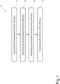
- Fig. 1 shows step of a method 10 for determining and/or optimizing a lifetime of an LED gear according to an embodiment.
- the method 10 comprises the steps of:
- the lifetime of the LED gear can be determined for the specific installation of the gear, i.e., for the actual use case / application of the LED gear. This will results in a more realistic lifetime estimation compared to a general estimation provided by a lifetime table in an LED gear datasheet.
- the lifetime of the LED gear that is determined in step 14 can be a "total" expected lifetime of the LED gear. This total expected lifetime may be determined as the shorter one of: the expected thermal lifetime and the expected memory lifetime.
- the expected thermal lifetime can be an estimated lifetime of an LED gear component until its failure due to thermal strain
- the expected memory lifetime can be an estimated lifetime of a memory of the LED gear due to an intensity of use.
- the first and second information can be received remotely, e.g., at a remote device.
- This remote device can then calculate the LED gear lifetime.
- the user can read out the first and second information from the LED gear. This data can then be analyzed. Depending on the data, the amount of guaranteed lifetime hours can be determined individually (customized for the given application, in the given luminaire, the LED module, the LED current, the typical ambient temperature, etc.).
- the first information may relate to thermal lifetime limitations of the LED gear components.
- the first information comprises a number of parameters which can determine the thermal load on at least one electronic component of the LED gear. These parameters can comprise: an LED voltage, an LED current, an LED gear temperature, a mains voltage and/or a mains frequency.
- the at least one electronic component can comprise one or more electrolytic capacitors (ECAP) of the LED gear.
- ECAP electrolytic capacitors
- the thermal lifetime of the LED gear depends on the temperature of the ECAP(s) during operation. This means that to extend the thermal lifetime of the gear, more resilient (and also more expensive) ECAPs are required and/or the components around the ECAP need to be adapted to decrease the ambient temperature of the ECAP, e.g., by using better MOSFETs, larger magnetics or better (more expensive) ferrite core materials.
- cheaper ECAPs would be sufficient, as the actual use case is less demanding.
- it can be found that less expensive LED gear components, e.g. ECAPs are sufficient for a specific application.
- the second information may relate to memory lifetime limitations of the LED gear memory.
- the memory can comprise a flash memory and/or a RAM (random access memory).
- the second information can comprise the number of erase/write/read cycles and/or the amount of data (e.g., in bits) transferred to / received from the memory over a period of time or until know.
- the number of memory erase/write/read (or write/erase) cycles can be correlated to the number of mains on/off cycles of the LED gear. This is because data is usually written to flash at mains off (for instance, while the microcontroller is buffered with a, e.g., 3.3V supply voltage for several hundreds of milliseconds after the mains voltage is turned off).
- the more data the LED gear needs to dynamically save to memory e.g. logging data, user settings, etc.
- the memory lifetime of the LED gear can vary greatly depending on the actual use of the memory. For instance, if a large percentage of all logging/settings data that is stored in the memory is always updated at mains off, the memory lifetime will be decreased. However, this "worst case" scenario will not occur in most cases, because a user may not use all software features of the LED gear (at a time). Thus, by calculating an expected memory lifetime based on (the second) information from the installed LED gear, a more realistic and application specific memory lifetime estimation can be provided.
- Fig. 2 shows further steps of the method 10 shown in Fig. 1 according to an embodiment.
- the method 10 may comprise the further step of:
- the optimized memory usage can be defined by an adjusted (i.e., optimized) number of erase/write/read cycles and/or an adjusted (i.e., optimized) amount of data transferred to/from the memory.
- the expected thermal lifetime of the LED gear e.g. of the ECAP(s) is calculated, for instance, based on thermal conditions (the first information).
- the memory writing frequency and data amount can then be adjusted such that the expected memory lifetime does not unnecessarily extend beyond this thermal lifetime expectation. In other words, the shorter the thermal lifetime expectation, the higher the data amount and frequency of the data written into the memory.
- the adjusted data amount and erase/write/read numbers can be calculated directly as a function of the thermal constrains on the LED gear components, in particular on the ECAP, (e.g., determined for example by the temperature of the LED gear, the LED current and/or the LED voltage). These thermal constraints can be represented by the first information.
- the method 10 may comprise the further step of:
- an intelligent LED gear can be realized with can adaptively optimize itself, in particular its memory usage, with regards to the expected LED gear lifetime.
- a user can adapt the LED gear functionality based on the expected memory lifetime.
- the number of software features offered by the LED gear can be adjusted to match the memory lifetime to a target lifetime of the LED gear and/or to a thermal lifetime limitation.
- the number of possible mains on/off cycles can be made transparent to a user of the LED gear.
- the user can then influence that number by activating or disabling certain software features.
- the user is not interested in the internal LED gear temperature logging (which could be used for several statistic reasons) he could simply disable that feature and by that increasing the number of mains on/off cycles (and therefore increase the expected memory lifetime, once the flash memory write/erase cycles become a limiting factor).
- software features which put a greater load on the memory can be activated, e.g., logging LED gear internal temperatures with a fine granularity.
- the activation and deactivation of software features as well as the readout of the guaranteed mains on/off cycles can be done via an external interface, e.g., with an external device which is connected to the LED gear via a communication connection.
- the maximum LED current can be reduced in case the memory lifetime has been estimated to be very long (in view of the data strain) .
- the thermal lifetime of the LED gear can be enhanced in order to increase the total lifetime of the LED gear.
- the method 10 can comprise the further step of:
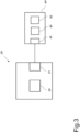
- Fig. 3 shows a schematic diagram of a device 30 for determining and/or optimizing a lifetime of the LED gear 40 according to an embodiment.
- the device 30 comprises a communication interface 31 configured to receive first information from the LED gear 40, the first information representing a thermal load on at least one electronic component 42, in particular an electrolytic capacitor, of the LED gear 40.
- the communication interface 31 is further configured to receive second information from the LED gear 40, the second information representing a number of read/write cycles of a memory 43 of the LED gear 40 and/or an amount of data transferred to/from the memory 43 of the LED gear 40.
- the device 30 further comprises a processor 32 configured to calculate an expected thermal lifetime of the LED gear 40 based on the first information and to calculate an expected memory lifetime of the LED gear 40 based on the second information; wherein the processor 32 is configured to determine the lifetime of the LED gear 40 based on the expected thermal lifetime and the expected memory lifetime.
- the device 30 can be a computing device and/or a communication device, e.g., a laptop or a smartphone.
- the device 30 can be configured to carry out the method 10 as shown in Figs. 1 and 2 .
- the processor 32 can be a microprocessor of the device 30.
- the LED gear 40 can comprise means to detect the first and/or second information.
- the LED gear 40 can comprise sensor units, such as a temperature sensor to measure an internal or ambient temperature, or a voltage/current sensor to measure a voltage and/or current supplied to the LED.
- the LED gear 40 can comprise a microcontroller which is configured to record the memory usage.
- the communication interface 31 of the device 30 can be connected to a corresponding communication interface 41 of the LED gear.
- each of the communication interfaces 31, 41 can be a wireless interface, e.g., a Bluetooth or Wifi interface.
- the device 30 can be a remote device which is wirelessly connected to the LED gear 40.
- Each of the communication interfaces 31, 41 could also be a wire-bound interface, e.g. a DALI interfaces. As such, the device can be connected to the LED gear 40 by a wire-bound connection.
- the device 30 can even be integrated in a housing of the LED gear 40.
- the processor 32 can be configured to calculate the optimized memory usage for the LED gear memory 43 for which the expected memory lifetime does not deviate from the expected thermal lifetime by more than a threshold value.
- the device 30 can be configured to control the LED gear 40 to adapt its operation, in particular the operation of its memory, based on the optimized memory usage. For instance, the device 30 can send a control command to the LED gear (e.g., via the interface 31), wherein, upon receiving the control command, the LED gear 40 is configured to adapt its memory usage.
- the device 30 can also be configured to display the optimized memory usage and/or to send this information to a further device, such that a user can adapt the LED gear 40 accordingly.
- the device 30 can be configured to control the LED gear 40 to adapt the maximum LED current that is provided by the LED gear to an LED load, e.g., an LED module, depending on the expected thermal and/or memory lifetime(s) of the LED gear 40.
- the device 30 can control the LED gear 40 to reduce a maximum LED current in case the expected memory lifetime is bigger than a further threshold value and/or to increase the maximum LED current in case the expected thermal lifetime is bigger than the expected memory lifetime.
- the threshold value and the further threshold value can be stored in a memory of the device 30.
- Fig. 4A shows a schematic diagram of the LED gear 40 according to an embodiment.
- the LED gear 40 is connected to an LED module 50 and provides a power supply to the LED module 50.
- the LED gear 40 and the LED module 50 can form an LED luminaire.
- the LED gear shown in Fig. 4A is further connected to a DALI bus, via its communication interface 41, e.g. a DALI interface, and to a mains supply via a mains connection 45.
- a DALI bus via its communication interface 41, e.g. a DALI interface
- a mains supply via a mains connection 45.
- the LED gear 40 has certain operating conditions, such as its ambient temperature T a (which can be influenced by the luminaire design and the ambient temperature of the luminaire itself T a_lum ), the forward voltage and temperature of the connected LED module V LED and T c_mod , the selected LED current I LED and the mains voltage V mains (and frequency f mains ).
- the LED gear case temperature T c will have a certain value. Any number of these parameters can be forwarded by the LED gear 40 as first information to the device 30 via the communication interface 41.
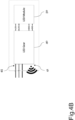
- Fig. 4B shows a schematic diagram of the LED gear 40, wherein the communication interface is a wireless interface, e.g. Bluetooth or Wifi, instead of a wire-bound interface.
- the communication interface is a wireless interface, e.g. Bluetooth or Wifi, instead of a wire-bound interface.
- a user can read out the first information (e.g. an LED voltage, an LED current, an LED gear temperature, a mains voltage and frequency) and/or the second information via the interface 41. Based on these parameters, an expected lifetime of the LED gear 40 can be calculated.
- the LED gear 40 can be connected to a communication network, such as the internet, via the communication interface 41.
- a user could then directly access the gear 40, e.g., by having access to a wireless network the LED gear is connected to, or by having access to a computer which acts as a master on the DALI bus.
- the lifetime of the LED gear 40 is limited by both thermals constraints (e.g., component temperatures; usually temperatures of electrolytic capacitors, ECAPs) as well as the memory usage, e.g., of the flash memory used in a microcontroller of the LED gear 40.
- thermals constraints e.g., component temperatures; usually temperatures of electrolytic capacitors, ECAPs
- the memory usage e.g., of the flash memory used in a microcontroller of the LED gear 40.
- the manufacturer of a microcontrollers guarantees for each flash page (whereas one page has a size of 2kB) a certain number (e.g., up to 10,000) erase cycles until the memory can be corrupted. This means each page can be completely written and erased for 10,000 times. Writing to a page, and erasing, typically happens when data is to be stored persistently. This happens, e.g., when the LED gear 40 stores logging data.
- the logging data can comprise mains voltage, temperature of the LED module, temperature of the LED gear, LED voltage, etc.
- the more data gets logged the more diagnostic information can be provided for a user (e.g. for predictive maintenance purpose). But, the more data gets logged, the more likely the mentioned characteristics of the flash memory gets the limiting factor when it comes to guaranteed lifetime.
- a user can enable/select or disable/de-select different logging features at the LED gear or directly in the end-application. Based on the selection, the user gets an estimation of the LED gear lifetime. Besides selection or de-selection of different data logging possibilities, the user might also predict how often the mains voltage of the LED gear is turned off. As the data is often only stored to flash memory only when mains OFF is detected, the flash memory limitation can limit the number of mains cycles the LED gear 40 sees during its lifetime. However, it is also possible that data is written to flash memory always when the data is changed (although mains remains ON all the time). In these applications flash memory might be the limiting factor much sooner.
- the LED gear 40 might withstand e.g. 40,000 mains cycles (if data is written to flash memory at each mains OFF). If only half of the data logging features are enabled the LED gear 40 the number of possible mains cycles could be increased to e.g. 60,000. If data is written to flash memory periodically (e.g. each 10s) the flash memory limitation will limit the possible lifetime of the LED gear 40. The less data logging features enabled, the longer the lifetime will be in this case.
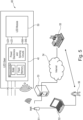
- Fig. 5 shows a schematic diagram of a system 60 according to an embodiment.
- the system 60 comprises the LED gear 40 and the device 30 for determining and/or optimizing a lifetime of the LED gear 40 as, e.g., shown in Fig. 3 .
- the LED gear 40 can be configured to transmit the first and the second information to the device 30.
- the LED gear 40 can comprise a microcontroller.
- the memory 43 of the LED gear 40 can comprise a flash memory and/or a RAM (random access memory) of the microcontroller.
- the LED gear 40 can further comprise power electronics and/or sensing circuits.
- the at least one electronic component 42 can be a power electronic component.
- the sensing circuits can be configured to sense LED gear parameters, e.g. internal temperature (s), which can form at least a part of the first information.
- the device 30 can be a workstation 52 or a server 53 and can be connected to the LED gear 40 via a wireless communication connection, e.g., using a wireless access point 51 or border router.
- a user 56 can enable / disable logging features of the LED gear 40 on the workstation 52 or server 53 using a configuration tool with a graphical user interface.
- the configuration tool can report back an estimated number of mains cycles or an estimated lifetime of the flash memory.
- the user 56 might readout other data from the LED gear such as gear temperature, V LED , I LED or V mains .
- the user 56 can report all the data to another entity 55, e.g., an LED gear manufacturer or supplier. Based on all the data the LED gear manufacturer 55 can determine an expected LED gear lifetime for the given application.
- the manufacturer may send a "lock" code to the user 56 which the user can send to the LED gear 40. For instance, if the gear 40 receives the lock code, no further changes of logging features are possible (otherwise the user 56 could again enable other logging features which would not be constituent with the estimated lifetime).
- the LED gear manufacturer 55 could also have access to the LED gear 40 directly. This could be realized e.g. via the internet 54, a server 53 in the network of the user and the wireless access point 51 or border router. In this case, the LED gear manufacturer 55 can readout the mentioned data autonomously and determine the estimated lifetime which then is reported to the user 56. The user 56 might be able to enable / disable logging features of the given LED gear 40 in the given application on a web based platform provided by the LED gear manufacturer 55.
Landscapes
- Circuit Arrangement For Electric Light Sources In General (AREA)
- Techniques For Improving Reliability Of Storages (AREA)
Abstract
Description
- The invention relates to a method and a device for determining and/or optimizing a lifetime of an LED gear, such as an LED driver. The invention further relates to a system comprising the device and the LED gear.
- The expected lifetime of an LED gear, such an LED driver, typically depends on its temperature during operation. This temperature is usually determined by the ambient temperature and by the output current provided by the LED gear.
- It is known to show the expected lifetimes of an LED gear for certain combinations of output currents and ambient temperatures in so-called lifetime tables. These lifetime tables are often printed in the datasheet of the LED gear.
- For example, a lifetime table of a conventional LED driver may show that if the driver runs at an ambient temperature of e.g. 50°C and provides an output current of e.g. 400 mA (at 1000 dimlevel) to a connected LED module, the expected LED driver temperature Tc is 80°C which may correspond to a lifetime of 50,000 h. This information can be used when choosing and/or qualifying an LED driver for certain LED luminaires. However, since the LED driver will not operate continuously at a dimlevel of 100%, the actual lifetime of the driver might exceed the value shown in the lifetime table. Thus, lifetime tables do often not show "realistic" lifetime expectations of LED drivers at their actual installation sites.
- Often, the specifications of LED gear require that a minimum lifetime of the gear - when operated at the most demanding operating point - needs to be equal to or larger a certain duration. This requirement can lead to increased component costs, as more resilient and thus more expensive components are used to reach the minimal lifetime. However, in a real life application, the LED gear is often operated at less demanding conditions. Thus, cheaper components would have been sufficient to reach the target lifetime.
- A further limiting factor of LED gear lifetime can be the number of write/erase cycles of a microcontroller flash memory of the gear. For example, a memory of the LED gear can have a lifetime of 10k write/erase cycles.
- Thus, it is an objective of the invention to provide an improved method and an improved device for determining and/or optimizing the lifetime of an LED gear, which avoid the above-mentioned disadvantages.
- The object of the present invention is achieved by the solution provided in the enclosed independent claims. Advantageous implementations of the present invention are further defined in the dependent claims.
- According to a first aspect, the invention relates to a method for determining and/or optimizing a lifetime of an LED gear. The method comprises the steps of:
- receiving first information from the LED gear, the first information representing a thermal load on at least one electronic component, in particular an electrolytic capacitor, of the LED gear;
- receiving second information from the LED gear, the second information representing a number of write/erase/read cycles of a memory of the LED gear and/or an amount of data transferred to/from the memory of the LED gear;
- calculating an expected thermal lifetime of the LED gear based on the first information, and calculating an expected memory lifetime of the LED gear based on the second information; and
- determining the lifetime of the LED gear based on the expected thermal lifetime and the expected memory lifetime.
- This achieves the advantage that the lifetime of the LED gear can be determined more accurately based on the actual use of the LED gear, i.e., based on real world data from the LED gear. Thereby, both the temperature of the LED gear and the memory usage can be considered.
- The LED gear can be a device for supplying an LED load. For example, the LED gear can be connected to a number of LED luminaires or modules and can power the LED luminaires or modules, e.g., by supplying them with an LED current and/or voltage. For example, the LED gear is an LED driver.
- The lifetime of the LED gear can be defined by a minimum number of operating hours, e.g., 50,000 h.
- The first information can comprise any combination of the following parameters of the LED gear: an LED voltage, an LED current, an LED gear temperature, a mains voltage and/or a mains frequency. In particular, the thermal load on the at least one electronic component of the LED gear depends on these parameters.
- The at least one electronic component can comprise one or more electrolytic capacitors (ECAP) of the LED gear. Typically, the thermal lifetime of the LED gear depends on the temperature of the ECAP(s) during operation. The ECAP is often the first point of failure due to temperature strain in the LED gear. In particular, the higher the thermal load and/or the thermal strain on the ECAP, the shorter the expected (thermal) lifetime of the ECAP and, thus, the LED gear.
- The second information can comprise the number of erase/write/read cycles (also referred to as: read/erase/write cycles, or shorter: write/erase cycles) and/or the amount of data (e.g., in bits) transferred to / received from the memory over a period of time or until know.
- The memory of the LED gear can comprise a flash memory and/or a RAM (random access memory). For instance, the memory has a limited lifetime determined by a maximum number of erase/write/read cycles and/or by a maximum amount of data transferred to/from the memory. In particular, the lower the update/writing frequency and the lower the amount of data written into the memory, the higher the lifetime of the memory and, thus, the LED gear.
- The determined lifetime of the LED gear can be an expected total lifetime of the LED gear. For instance, the lifetime parameters (lifetime of the LED gear, expected thermal lifetime and the expected memory lifetime) can be calculated under the assumption that the LED gear continues to be operated according to the received first and second information.
- The received first and second information can comprise or be based on parameters which were recorded over time and/or averaged over time. I.e., the thermal load can be an average thermal load and the read/write cycles and/or amount of data can be average read/write cycles and/or average amount of data.
- The first and the second information can be received via a communication interface of the LED gear, e.g. a wireless or a wire-bound interface. For instance, the first and the second information is received at a computing device connected to the communication interface of the gear. The computing device can be an external device which is remote to the LED gear, e.g. a laptop or smartphone.
- For example, the expected thermal lifetime is calculated by feeding a dedicated formula or an algorithm with any combination of the following parameters: an LED voltage, an LED current, an LED gear temperature, a mains voltage and/or a mains frequency.
- Likewise, the expected memory lifetime can be calculated by feeding a dedicated formula or an algorithm with values representing the number of erase/write/read cycles and/or the amount of data transferred to/from the memory.
- In an embodiment, the lifetime of the LED gear is determined as the shorter one of the two parameters expected thermal lifetime and expected memory lifetime.
- In an embodiment, the method further comprises the step of:
- calculating an optimized memory usage for which the expected memory lifetime does not deviate from the expected thermal lifetime by more than a threshold value.
- This achieves the advantage that the memory can be optimally utilized without additionally shortening the lifetime of the LED gear. At the same time, unnecessary constraints on the memory usage can be avoided should the expected thermal lifetime be much shorter than the expected memory lifetime. In other words, the shorter the expected thermal lifetime, the higher the allowed data amount and frequency of the data written into the memory.
- For example, at the optimized memory usage the expected memory lifetime does not exceed the expected thermal lifetime by more than the threshold value.
- The optimized memory usage can be defined by an adjusted number of erase/write/read cycles and/or an adjusted amount of data transferred to/from the memory.
- To identify these "adjusted" parameters for the optimized memory usage, the expected memory lifetime can be calculated for varying erase/write/read cycle and/or data amount values, until the expected memory lifetime no longer deviates from the expected thermal lifetime by more than the threshold value.
- Alternatively, the adjusted parameters for the optimized memory usage can be calculated as a function of thermal constraints of the LED gear, such as a temperature of the LED gear, an LED current and/or an LED voltage.
- In an embodiment, the method comprises the further step of:
- adapting an operation of the LED gear, in particular of the memory of the LED gear, based on the optimized memory usage.
- For example, to reduce the memory usage certain features of the LED gear, such as temperature logging, can be deactivated. This reduces the number of erase/write/read cycles and/or the amount of transferred data and, thus, extends the expected memory lifetime.
- In an embodiment, the method comprises the further step of:
- reducing a maximum LED current provided by the LED gear in case the calculated expected memory lifetime exceeds a further threshold value.
- This achieves the advantage that in case of a very long memory lifetime also the thermal lifetime can be enhanced in order to increase the total lifetime of the LED gear. The maximum LED current can be the maximum current that is output by the LED gear, e.g., at a dimlevel of 100% (brightest setting).
- For example, the maximum LED current can be reduced below a current threshold value.
- In an embodiment, the method comprises the further step of:
- enhancing a maximum LED current provided by the LED gear in case the expected thermal lifetime exceeds the expected memory lifetime.
- This achieves the advantage that a higher LED performance can be allowed should the memory lifetime be the constraining factor of the total lifetime.
- For example, the maximum LED current can be increased above a further current threshold value.
- In another example, the method comprises the step of: reducing a maximum LED current provided by the LED gear in case the calculated expected thermal lifetime is shorter than the calculated expected memory lifetime.
- According to a second aspect, the invention relates to a device for determining and/or optimizing a lifetime of an LED gear. The device comprises a communication interface configured to receive first information from the LED gear, the first information representing a thermal load on at least one electronic component, in particular an electrolytic capacitor, of the LED gear; wherein the communication interface is further configured to receive second information from the LED gear, the second information representing a number of erase/write/read cycles of a memory of the LED gear and/or an amount of data transferred to/from the memory of the LED gear; and a processor configured to calculate an expected thermal lifetime of the LED gear based on the first information, and to calculate an expected memory lifetime of the LED gear based on the second information; wherein the processor is configured to determine the lifetime of the LED gear based on the expected thermal lifetime and the expected memory lifetime.
- The device of the second aspect of the invention achieves the same advantages as the method of the first aspect of the invention, and may be extended by respective implementations as described above for the method of the first aspect.
- In an embodiment, the processor is configured to determine the lifetime of the LED gear as the shorter one of the two parameters expected thermal lifetime and expected memory lifetime.
- In an embodiment, the processor is further configured to calculate an optimized memory usage for which the expected memory lifetime does not deviate from the expected thermal lifetime by more than a threshold value.
- In an embodiment, the device is configured to control the LED gear to adapt its operation, in particular the operation of its memory, based on the optimized memory usage.
- In an embodiment, the device is configured to control the LED gear to reduce a maximum LED current provided by the LED gear in case the expected memory lifetime exceeds a further threshold value.
- In an embodiment, the device is configured to control the LED gear to increase a maximum LED current provided by the LED gear in case the expected thermal lifetime exceeds the expected memory lifetime.
- For instance, the device can control the LED to adapt its operation and/or to reduce respectively increase its LED current by generation and transmitting a control command to the LED gear via the communication interface.
- In an embodiment, the device is a remote device, such as a computer or smartphone, which is wirelessly connected to the LED gear.
- In an embodiment, the device is connected to the LED gear by a wire-bound connection and/or the device is integrated in a housing of the LED gear.
- The device of the second aspect of the invention can be adapted to carry out the method of the first aspect of the invention.
- According to a third aspect, the invention relates to a system comprising: the device according to the second aspect of the invention; and the LED gear.
- The LED gear can comprise at least one electronic component, in particular the electrolytic capacitor, a memory, and a communication interface.
- For example, the LED gear is configured to transmit the first and the second information to the device, e.g. via its communication interface. In particular, the device and the LED gear can be configured to communicate via their respective communication interfaces.
- The invention will be explained in the followings together with the figures.
- Fig. 1
- shows steps of a method for determining and/or optimizing a lifetime of an LED gear according to an embodiment;
- Fig. 2
- shows further steps of the method shown in
Fig. 1 according to an embodiment; - Fig. 3
- shows a schematic diagram of a device for determining and/or optimizing a lifetime of an LED gear according to an embodiment;
- Fig. 4A
- shows a schematic diagram of an LED gear according to an embodiment;
- Fig. 4B
- shows a schematic diagram of an LED gear according to an embodiment; and
- Fig. 5
- shows a schematic diagram of a system according to an embodiment.
-
Fig. 1 shows step of amethod 10 for determining and/or optimizing a lifetime of an LED gear according to an embodiment. - The
method 10 comprises the steps of: - receiving 11 first information from the LED gear, the first information representing a thermal load on at least one electronic component, in particular an electrolytic capacitor, of the LED gear;
- receiving 12 second information from the LED gear, the second information representing a number of erase/write/read cycles of a memory of the LED gear and/or an amount of data transferred to/from the memory of the LED gear; and
- calculating 13 an expected thermal lifetime of the LED gear based on the first information, and calculating an expected memory lifetime of the LED gear based on the second information; and
- determining 14 the lifetime of the LED gear based on the expected thermal lifetime and the expected memory lifetime.
- In this way, the lifetime of the LED gear can be determined for the specific installation of the gear, i.e., for the actual use case / application of the LED gear. This will results in a more realistic lifetime estimation compared to a general estimation provided by a lifetime table in an LED gear datasheet.
- The lifetime of the LED gear that is determined in
step 14 can be a "total" expected lifetime of the LED gear. This total expected lifetime may be determined as the shorter one of: the expected thermal lifetime and the expected memory lifetime. - The expected thermal lifetime can be an estimated lifetime of an LED gear component until its failure due to thermal strain, and the expected memory lifetime can be an estimated lifetime of a memory of the LED gear due to an intensity of use.
- The first and second information can be received remotely, e.g., at a remote device. This remote device can then calculate the LED gear lifetime.
- For example, during an installation of the LED gear or directly in the field in the end application, the user can read out the first and second information from the LED gear. This data can then be analyzed. Depending on the data, the amount of guaranteed lifetime hours can be determined individually (customized for the given application, in the given luminaire, the LED module, the LED current, the typical ambient temperature, etc.).
- The first information may relate to thermal lifetime limitations of the LED gear components. In particular, the first information comprises a number of parameters which can determine the thermal load on at least one electronic component of the LED gear. These parameters can comprise: an LED voltage, an LED current, an LED gear temperature, a mains voltage and/or a mains frequency.
- The at least one electronic component can comprise one or more electrolytic capacitors (ECAP) of the LED gear. Typically, the thermal lifetime of the LED gear depends on the temperature of the ECAP(s) during operation. This means that to extend the thermal lifetime of the gear, more resilient (and also more expensive) ECAPs are required and/or the components around the ECAP need to be adapted to decrease the ambient temperature of the ECAP, e.g., by using better MOSFETs, larger magnetics or better (more expensive) ferrite core materials. However, for many application scenarios, cheaper ECAPs would be sufficient, as the actual use case is less demanding. Thus, by providing a more realistic lifetime estimation, it can be found that less expensive LED gear components, e.g. ECAPs, are sufficient for a specific application.
- The second information may relate to memory lifetime limitations of the LED gear memory. The memory can comprise a flash memory and/or a RAM (random access memory). The second information can comprise the number of erase/write/read cycles and/or the amount of data (e.g., in bits) transferred to / received from the memory over a period of time or until know.
- For example, the number of memory erase/write/read (or write/erase) cycles can be correlated to the number of mains on/off cycles of the LED gear. This is because data is usually written to flash at mains off (for instance, while the microcontroller is buffered with a, e.g., 3.3V supply voltage for several hundreds of milliseconds after the mains voltage is turned off). In general, the more data the LED gear needs to dynamically save to memory (e.g. logging data, user settings, etc.), the less mains on / mains off cycles (= flash write / erase cycles) are supported before a maximum number of flash write/erase cycles is reached. Afterwards flash memory can get corrupted which may lead to LED gear malfunction or destruction.
- Thus, the memory lifetime of the LED gear can vary greatly depending on the actual use of the memory. For instance, if a large percentage of all logging/settings data that is stored in the memory is always updated at mains off, the memory lifetime will be decreased. However, this "worst case" scenario will not occur in most cases, because a user may not use all software features of the LED gear (at a time). Thus, by calculating an expected memory lifetime based on (the second) information from the installed LED gear, a more realistic and application specific memory lifetime estimation can be provided.
- In contrast, for a conventional LED gear often the worst case scenario will be assumed and, as a consequence, the amount of data that is dynamically stored to flash memory will be limited (e.g. by limiting data that is logged during the operation of the LED gear) and/or larger (more expensive) microcontrollers which have more flash memory available will be used (which allows to store more data as the limitation of write/erase cycle is e.g. 10k cycles per "flash page" whereas one flash page usually is 2048 bytes in the controllers that are offered today). These disadvantages can be avoided by calculating the expected memory lifetime based on the actual memory usage using the second information according to the
method 10. -
Fig. 2 shows further steps of themethod 10 shown inFig. 1 according to an embodiment. - For example, the
method 10 may comprise the further step of: - calculating 15 an optimized memory usage for which the expected memory lifetime does not deviate from the expected thermal lifetime (calculated in step 13) by more than a threshold value.
- The optimized memory usage can be defined by an adjusted (i.e., optimized) number of erase/write/read cycles and/or an adjusted (i.e., optimized) amount of data transferred to/from the memory.
- For example, in a first step, the expected thermal lifetime of the LED gear, e.g. of the ECAP(s), is calculated, for instance, based on thermal conditions (the first information). The memory writing frequency and data amount can then be adjusted such that the expected memory lifetime does not unnecessarily extend beyond this thermal lifetime expectation. In other words, the shorter the thermal lifetime expectation, the higher the data amount and frequency of the data written into the memory.
- In an example, it is not necessary to first determine the total LED gear lifetime or the expected memory lifetime in order to calculate the adjusted number of erase/write/read cycles and/or the adjusted amount of data. Instead, for example the adjusted data amount and erase/write/read numbers can be calculated directly as a function of the thermal constrains on the LED gear components, in particular on the ECAP, (e.g., determined for example by the temperature of the LED gear, the LED current and/or the LED voltage). These thermal constraints can be represented by the first information.
- The
method 10 may comprise the further step of: - adapting 16 the operation of the LED gear, in particular of the memory of the LED gear, based on the optimized memory usage.
- This
adaption 16 can be carried out by the LED gear, e.g., prompted by a control command from an external device or by a user. - In this way, an intelligent LED gear can be realized with can adaptively optimize itself, in particular its memory usage, with regards to the expected LED gear lifetime.
- Furthermore, a user can adapt the LED gear functionality based on the expected memory lifetime. For example, the number of software features offered by the LED gear can be adjusted to match the memory lifetime to a target lifetime of the LED gear and/or to a thermal lifetime limitation. For instance, the number of possible mains on/off cycles (before flash memory malfunctions might occur) can be made transparent to a user of the LED gear. The user can then influence that number by activating or disabling certain software features. E.g., if the user is not interested in the internal LED gear temperature logging (which could be used for several statistic reasons) he could simply disable that feature and by that increasing the number of mains on/off cycles (and therefore increase the expected memory lifetime, once the flash memory write/erase cycles become a limiting factor). If a shorter memory lifetime is acceptable for a certain use-case, software features which put a greater load on the memory can be activated, e.g., logging LED gear internal temperatures with a fine granularity.
- This means, e.g., if all software features (that require the dynamic storage of some data) are active, the number of mains on/off cycles is, e.g., 40,000 before a flash memory malfunction is likely to happen. If the user is not interested in the logging of certain functions, for example "lamp operating hours", he can disable that features which will increase the number of mains on/off cycles (as less data needs to be stored dynamically). The same can be done for other features, such as the logging of internal gear temperatures, or the energy calculation features our recent gears have.
- For example, if the user has an installation which is powered by mains all the time (i.e., mains on/off cycles occur very seldom), the flash memory write/erase cycles are less likely to be a limiting factor. In these installations, the gear can activate more or even all features and/or log all available data, as the data remains, e.g., only in RAM and is stored to flash very less frequently.
- The activation and deactivation of software features as well as the readout of the guaranteed mains on/off cycles can be done via an external interface, e.g., with an external device which is connected to the LED gear via a communication connection.
- As a further aspect, the operation of the LED driver can be set to at least two different scenarios. A first scenario is represented by the following step of the
method 10 shown inFig. 2 : - reducing 17 a maximum LED current provided by the LED gear in case the calculated expected memory lifetime exceeds a further threshold value.
- In other words, the maximum LED current can be reduced in case the memory lifetime has been estimated to be very long (in view of the data strain) . Thus, in case of a very long memory lifetime also the thermal lifetime of the LED gear can be enhanced in order to increase the total lifetime of the LED gear.
- Alternatively or additionally, the
method 10 can comprise the further step of: - enhancing 18 a maximum LED current provided by the LED gear in case the expected thermal lifetime is bigger than the expected memory lifetime.
- Thus, a higher maximum LED current can be proposed which might result in a lifetime restriction caused by the thermal conditions, which is lower than the lifetime expectation of the flash memory.
-
Fig. 3 shows a schematic diagram of adevice 30 for determining and/or optimizing a lifetime of theLED gear 40 according to an embodiment. - The
device 30 comprises acommunication interface 31 configured to receive first information from theLED gear 40, the first information representing a thermal load on at least oneelectronic component 42, in particular an electrolytic capacitor, of theLED gear 40. Thecommunication interface 31 is further configured to receive second information from theLED gear 40, the second information representing a number of read/write cycles of amemory 43 of theLED gear 40 and/or an amount of data transferred to/from thememory 43 of theLED gear 40. Thedevice 30 further comprises aprocessor 32 configured to calculate an expected thermal lifetime of theLED gear 40 based on the first information and to calculate an expected memory lifetime of theLED gear 40 based on the second information; wherein theprocessor 32 is configured to determine the lifetime of theLED gear 40 based on the expected thermal lifetime and the expected memory lifetime. - The
device 30 can be a computing device and/or a communication device, e.g., a laptop or a smartphone. Thedevice 30 can be configured to carry out themethod 10 as shown inFigs. 1 and2 . - The
processor 32 can be a microprocessor of thedevice 30. - The
LED gear 40 can be a LED driver. The LED gear can be connected to an LED module and supply said LED module with an LED voltage and/or current. - The
LED gear 40 can comprise means to detect the first and/or second information. For example, theLED gear 40 can comprise sensor units, such as a temperature sensor to measure an internal or ambient temperature, or a voltage/current sensor to measure a voltage and/or current supplied to the LED. For instance, theLED gear 40 can comprise a microcontroller which is configured to record the memory usage. - To establish a communication connection, the
communication interface 31 of thedevice 30 can be connected to acorresponding communication interface 41 of the LED gear. - For instance, each of the communication interfaces 31, 41 can be a wireless interface, e.g., a Bluetooth or Wifi interface. As such, the
device 30 can be a remote device which is wirelessly connected to theLED gear 40. - Each of the communication interfaces 31, 41 could also be a wire-bound interface, e.g. a DALI interfaces. As such, the device can be connected to the
LED gear 40 by a wire-bound connection. - In an example, the
device 30 can even be integrated in a housing of theLED gear 40. - The
processor 32 can be configured to calculate the optimized memory usage for theLED gear memory 43 for which the expected memory lifetime does not deviate from the expected thermal lifetime by more than a threshold value. - Based on this information, the
device 30 can be configured to control theLED gear 40 to adapt its operation, in particular the operation of its memory, based on the optimized memory usage. For instance, thedevice 30 can send a control command to the LED gear (e.g., via the interface 31), wherein, upon receiving the control command, theLED gear 40 is configured to adapt its memory usage. - The
device 30 can also be configured to display the optimized memory usage and/or to send this information to a further device, such that a user can adapt theLED gear 40 accordingly. - According to another example, the
device 30 can be configured to control theLED gear 40 to adapt the maximum LED current that is provided by the LED gear to an LED load, e.g., an LED module, depending on the expected thermal and/or memory lifetime(s) of theLED gear 40. For instance, thedevice 30 can control theLED gear 40 to reduce a maximum LED current in case the expected memory lifetime is bigger than a further threshold value and/or to increase the maximum LED current in case the expected thermal lifetime is bigger than the expected memory lifetime. - The threshold value and the further threshold value can be stored in a memory of the
device 30. -
Fig. 4A shows a schematic diagram of theLED gear 40 according to an embodiment. - The
LED gear 40 is connected to anLED module 50 and provides a power supply to theLED module 50. For example, theLED gear 40 and theLED module 50 can form an LED luminaire. - The LED gear shown in
Fig. 4A is further connected to a DALI bus, via itscommunication interface 41, e.g. a DALI interface, and to a mains supply via amains connection 45. - Depending on the end application, the
LED gear 40 has certain operating conditions, such as its ambient temperature Ta (which can be influenced by the luminaire design and the ambient temperature of the luminaire itself Ta_lum), the forward voltage and temperature of the connected LED module VLED and Tc_mod, the selected LED current ILED and the mains voltage Vmains (and frequency fmains). Depending on the output power (Pout = VLED * ILED) and the ambient temperature of the LED gear Ta the LED gear case temperature Tc will have a certain value. Any number of these parameters can be forwarded by theLED gear 40 as first information to thedevice 30 via thecommunication interface 41. -
Fig. 4B shows a schematic diagram of theLED gear 40, wherein the communication interface is a wireless interface, e.g. Bluetooth or Wifi, instead of a wire-bound interface. - A user can read out the first information (e.g. an LED voltage, an LED current, an LED gear temperature, a mains voltage and frequency) and/or the second information via the
interface 41. Based on these parameters, an expected lifetime of theLED gear 40 can be calculated. For instance, theLED gear 40 can be connected to a communication network, such as the internet, via thecommunication interface 41. A user could then directly access thegear 40, e.g., by having access to a wireless network the LED gear is connected to, or by having access to a computer which acts as a master on the DALI bus. - Typically, the lifetime of the
LED gear 40 is limited by both thermals constraints (e.g., component temperatures; usually temperatures of electrolytic capacitors, ECAPs) as well as the memory usage, e.g., of the flash memory used in a microcontroller of theLED gear 40. For example, the manufacturer of a microcontrollers guarantees for each flash page (whereas one page has a size of 2kB) a certain number (e.g., up to 10,000) erase cycles until the memory can be corrupted. This means each page can be completely written and erased for 10,000 times. Writing to a page, and erasing, typically happens when data is to be stored persistently. This happens, e.g., when theLED gear 40 stores logging data. For example, the logging data can comprise mains voltage, temperature of the LED module, temperature of the LED gear, LED voltage, etc. The more data gets logged, the more diagnostic information can be provided for a user (e.g. for predictive maintenance purpose). But, the more data gets logged, the more likely the mentioned characteristics of the flash memory gets the limiting factor when it comes to guaranteed lifetime. - A user can enable/select or disable/de-select different logging features at the LED gear or directly in the end-application. Based on the selection, the user gets an estimation of the LED gear lifetime. Besides selection or de-selection of different data logging possibilities, the user might also predict how often the mains voltage of the LED gear is turned off. As the data is often only stored to flash memory only when mains OFF is detected, the flash memory limitation can limit the number of mains cycles the
LED gear 40 sees during its lifetime. However, it is also possible that data is written to flash memory always when the data is changed (although mains remains ON all the time). In these applications flash memory might be the limiting factor much sooner. - For example, if all data logging features are enabled (selected) the
LED gear 40 might withstand e.g. 40,000 mains cycles (if data is written to flash memory at each mains OFF). If only half of the data logging features are enabled theLED gear 40 the number of possible mains cycles could be increased to e.g. 60,000. If data is written to flash memory periodically (e.g. each 10s) the flash memory limitation will limit the possible lifetime of theLED gear 40. The less data logging features enabled, the longer the lifetime will be in this case. -
Fig. 5 shows a schematic diagram of asystem 60 according to an embodiment. Thesystem 60 comprises theLED gear 40 and thedevice 30 for determining and/or optimizing a lifetime of theLED gear 40 as, e.g., shown inFig. 3 . - The
LED gear 40 can be configured to transmit the first and the second information to thedevice 30. - The
LED gear 40 can comprise a microcontroller. Thememory 43 of theLED gear 40 can comprise a flash memory and/or a RAM (random access memory) of the microcontroller. TheLED gear 40 can further comprise power electronics and/or sensing circuits. The at least oneelectronic component 42 can be a power electronic component. The sensing circuits can be configured to sense LED gear parameters, e.g. internal temperature (s), which can form at least a part of the first information. - As shown in
Fig. 5 , thedevice 30 can be aworkstation 52 or aserver 53 and can be connected to theLED gear 40 via a wireless communication connection, e.g., using awireless access point 51 or border router. - For instance, a
user 56 can enable / disable logging features of theLED gear 40 on theworkstation 52 orserver 53 using a configuration tool with a graphical user interface. Depending on the enabled features and the particular LED gear type (that stores data to flash memory either periodically, on demand or always at mains OFF), the configuration tool can report back an estimated number of mains cycles or an estimated lifetime of the flash memory. - Additionally, the
user 56 might readout other data from the LED gear such as gear temperature, VLED, ILED or Vmains. Theuser 56 can report all the data to anotherentity 55, e.g., an LED gear manufacturer or supplier. Based on all the data theLED gear manufacturer 55 can determine an expected LED gear lifetime for the given application. The manufacturer may send a "lock" code to theuser 56 which the user can send to theLED gear 40. For instance, if thegear 40 receives the lock code, no further changes of logging features are possible (otherwise theuser 56 could again enable other logging features which would not be constituent with the estimated lifetime). - Alternatively, the
LED gear manufacturer 55 could also have access to theLED gear 40 directly. This could be realized e.g. via theinternet 54, aserver 53 in the network of the user and thewireless access point 51 or border router. In this case, theLED gear manufacturer 55 can readout the mentioned data autonomously and determine the estimated lifetime which then is reported to theuser 56. Theuser 56 might be able to enable / disable logging features of the givenLED gear 40 in the given application on a web based platform provided by theLED gear manufacturer 55. - Although the invention has been illustrated and described with respect to one or more implementations, equivalent alternations and modifications will occur to those skilled in the art upon the reading of the understanding of the specification and the annexed drawings. In addition, while a particular feature of the invention may have been disclosed with respect to only of the several implementations, such features may be combined with one or more other features of the other implementations as may be desired and advantage for any given or particular application.
Claims (15)
- A method (10) for determining and/or optimizing a lifetime of an LED gear (40), the method comprising the steps of:- receiving (11) first information from the LED gear (40), the first information representing a thermal load on at least one electronic component, in particular an electrolytic capacitor, of the LED gear (40);- receiving (12) second information from the LED gear (40), the second information representing a number of erase/write/read cycles of a memory (43) of the LED gear (40) and/or an amount of data transferred to/from the memory (43) of the LED gear (40);- calculating (13) an expected thermal lifetime of the LED gear (40) based on the first information, and calculating an expected memory lifetime of the LED gear (40) based on the second information; and- determining (14) the lifetime of the LED gear (40) based on the expected thermal lifetime and the expected memory lifetime.
- The method (10) of claim 1,
wherein the lifetime of the LED gear (40) is determined as the shorter one of the two parameters expected thermal lifetime and expected memory lifetime. - The method (10) of claim 1 or 2, further comprising the step of:- calculating (15) an optimized memory usage for which the expected memory lifetime does not deviate from the expected thermal lifetime by more than a threshold value.
- The method (10) of claim 3, further comprising the step of:- adapting (16) an operation of the LED gear (40), in particular of the memory (43) of the LED gear (40), based on the optimized memory usage.
- The method (10) of any one of the preceding claims, comprising the further step of:- reducing (17) a maximum LED current provided by the LED gear (40) in case the calculated expected memory lifetime exceeds a further threshold value.
- The method (10) of any one of the preceding claims, comprising the further step of:- enhancing (18) a maximum LED current (18) provided by the LED gear (40) in case the expected thermal lifetime exceeds the expected memory lifetime.
- A device (30) for determining and/or optimizing a lifetime of an LED gear (40), the device comprising:a communication interface (31) configured to receive first information from the LED gear (40), the first information representing a thermal load on at least one electronic component, in particular an electrolytic capacitor, of the LED gear (40);wherein the communication interface (31) is further configured to receive second information from the LED gear (40), the second information representing a number of erase/write/read cycles of a memory (43) of the LED gear (40) and/or an amount of data transferred to/from the memory (43) of the LED gear (40); anda processor (32) configured to calculate an expected thermal lifetime of the LED gear (40) based on the first information, and to calculate an expected memory lifetime of the LED gear (40) based on the second information;wherein the processor (32) is configured to determine the lifetime of the LED gear (40) based on the expected thermal lifetime and the expected memory lifetime.
- The device (30) of claim 7,
wherein the processor (32) is configured to determine the lifetime of the LED gear (40) as the shorter one of the two parameters expected thermal lifetime and expected memory lifetime. - The device (30) of claim 7 or 8,
wherein the processor (32) is further configured to calculate an optimized memory usage for which the expected memory lifetime does not deviate from the expected thermal lifetime by more than a threshold value. - The device (30) of claim 9,
wherein the device (30) is configured to control the LED gear (40) to adapt its operation, in particular the operation of its memory (43), based on the optimized memory usage. - The device (30) of any one of claims 7 to 10,
wherein the device (30) is configured to control the LED gear (40) to reduce a maximum LED current provided by the LED gear (40) in case the expected memory lifetime exceeds a further threshold value. - The device (30) of any one of claims 7 to 11,
wherein the device (30) is configured to control the LED gear (40) to increase a maximum LED current provided by the LED gear in case the expected thermal lifetime exceeds the expected memory lifetime. - The device (30) of any one of claims 7 to 12,
wherein the device (30) is a remote device, such as a computer or smartphone, which is wirelessly connected to the LED gear (40). - The device (30) of any one of claims 7 to 12,
wherein the device (20) is connected to the LED gear (40) by a wire-bound connection and/or wherein the device (30) is integrated in a housing of the LED gear (40). - A system (60) comprising:the device (30) of any one of claims 7 to 14; andthe LED gear (40).
Priority Applications (2)
| Application Number | Priority Date | Filing Date | Title |
|---|---|---|---|
| EP23163645.7A EP4436318B1 (en) | 2023-03-23 | 2023-03-23 | Method and device for determining and/or optimizing a lifetime of an led gear |
| PCT/EP2024/055795 WO2024194012A1 (en) | 2023-03-23 | 2024-03-06 | Method and device for determining and/or optimizing a lifetime of an led gear |
Applications Claiming Priority (1)
| Application Number | Priority Date | Filing Date | Title |
|---|---|---|---|
| EP23163645.7A EP4436318B1 (en) | 2023-03-23 | 2023-03-23 | Method and device for determining and/or optimizing a lifetime of an led gear |
Publications (2)
| Publication Number | Publication Date |
|---|---|
| EP4436318A1 true EP4436318A1 (en) | 2024-09-25 |
| EP4436318B1 EP4436318B1 (en) | 2025-07-16 |
Family
ID=85726344
Family Applications (1)
| Application Number | Title | Priority Date | Filing Date |
|---|---|---|---|
| EP23163645.7A Active EP4436318B1 (en) | 2023-03-23 | 2023-03-23 | Method and device for determining and/or optimizing a lifetime of an led gear |
Country Status (2)
| Country | Link |
|---|---|
| EP (1) | EP4436318B1 (en) |
| WO (1) | WO2024194012A1 (en) |
Citations (2)
| Publication number | Priority date | Publication date | Assignee | Title |
|---|---|---|---|---|
| US20110254554A1 (en) * | 2010-06-18 | 2011-10-20 | Xicato, Inc. | Led-based illumination module on-board diagnostics |
| CN108804777A (en) * | 2018-05-23 | 2018-11-13 | 东南大学 | A kind of LED illumination System life-span prediction method based on thermal coupling effect |
-
2023
- 2023-03-23 EP EP23163645.7A patent/EP4436318B1/en active Active
-
2024
- 2024-03-06 WO PCT/EP2024/055795 patent/WO2024194012A1/en not_active Ceased
Patent Citations (2)
| Publication number | Priority date | Publication date | Assignee | Title |
|---|---|---|---|---|
| US20110254554A1 (en) * | 2010-06-18 | 2011-10-20 | Xicato, Inc. | Led-based illumination module on-board diagnostics |
| CN108804777A (en) * | 2018-05-23 | 2018-11-13 | 东南大学 | A kind of LED illumination System life-span prediction method based on thermal coupling effect |
Non-Patent Citations (1)
| Title |
|---|
| ZHANG HUI: "A Viable Nontesting Method to Predict the Lifetime of LED Drivers", IEEE JOURNAL OF EMERGING AND SELECTED TOPICS IN POWER ELECTRONICS, IEEE, PISCATAWAY, NJ, USA, vol. 6, no. 3, 1 September 2018 (2018-09-01), pages 1246 - 1251, XP011688279, ISSN: 2168-6777, [retrieved on 20180807], DOI: 10.1109/JESTPE.2018.2826364 * |
Also Published As
| Publication number | Publication date |
|---|---|
| EP4436318B1 (en) | 2025-07-16 |
| WO2024194012A1 (en) | 2024-09-26 |
Similar Documents
| Publication | Publication Date | Title |
|---|---|---|
| US10595373B2 (en) | Methods and apparatuses to provide dimming for a light emitting diode system | |
| US9467052B2 (en) | Adaptive control scheme of voltage regulator for light and sinking load operation | |
| JP2010529548A5 (en) | ||
| EP2962412B1 (en) | Visible light communication with increased signal-to-noise ratio | |
| TW201516634A (en) | Redundant array of independent disks storage device, server system, and power management method thereof | |
| CN102646402A (en) | Backlight driving voltage control device, backlight driving voltage control method and television | |
| CN110764964B (en) | Storage device and control method thereof | |
| US20180158492A1 (en) | Storage device operating differently according to temperature of memory | |
| TWI591473B (en) | Power-off memory system and its device | |
| CN117112475B (en) | An I2C bus driving capability automatic adjustment system and method | |
| EP4436318B1 (en) | Method and device for determining and/or optimizing a lifetime of an led gear | |
| EP2477463A1 (en) | Apparatus and method for sensing failure | |
| CN114203243B (en) | Memory system and power supply circuit | |
| CN103248308A (en) | Method for controlling inverter | |
| CN113961060A (en) | Electronic device and power management method thereof | |
| KR100763331B1 (en) | Semiconductor memory device | |
| KR102839272B1 (en) | Storage device and operating method thereof | |
| US8667610B2 (en) | Portable computer and charging method thereof | |
| CN101094554B (en) | Method and ballast to start discharge lamp | |
| US20120109339A1 (en) | Life management circuit, an electronic system and a machine-implemented method for managing usage rates of multiple electronic components | |
| CN117953795A (en) | Display device and driving method thereof | |
| JP2021533724A (en) | Digitally addressable lighting interface (DALI) compatible communication device and corresponding method for sending messages through the communication bus. | |
| KR20240083977A (en) | Master device for identifying an address of a slave device, electronic device including the same, and operating method of the electronic device | |
| CN112055440B (en) | Light-emitting diode lamp string system with sequencing function and sequencing method | |
| CN107994925A (en) | A kind of method by power line communication |
Legal Events
| Date | Code | Title | Description |
|---|---|---|---|
| PUAI | Public reference made under article 153(3) epc to a published international application that has entered the european phase |
Free format text: ORIGINAL CODE: 0009012 |
|
| STAA | Information on the status of an ep patent application or granted ep patent |
Free format text: STATUS: THE APPLICATION HAS BEEN PUBLISHED |
|
| AK | Designated contracting states |
Kind code of ref document: A1 Designated state(s): AL AT BE BG CH CY CZ DE DK EE ES FI FR GB GR HR HU IE IS IT LI LT LU LV MC ME MK MT NL NO PL PT RO RS SE SI SK SM TR |
|
| STAA | Information on the status of an ep patent application or granted ep patent |
Free format text: STATUS: REQUEST FOR EXAMINATION WAS MADE |
|
| 17P | Request for examination filed |
Effective date: 20241009 |
|
| RBV | Designated contracting states (corrected) |
Designated state(s): AL AT BE BG CH CY CZ DE DK EE ES FI FR GB GR HR HU IE IS IT LI LT LU LV MC ME MK MT NL NO PL PT RO RS SE SI SK SM TR |
|
| GRAP | Despatch of communication of intention to grant a patent |
Free format text: ORIGINAL CODE: EPIDOSNIGR1 |
|
| STAA | Information on the status of an ep patent application or granted ep patent |
Free format text: STATUS: GRANT OF PATENT IS INTENDED |
|
| INTG | Intention to grant announced |
Effective date: 20250224 |
|
| GRAS | Grant fee paid |
Free format text: ORIGINAL CODE: EPIDOSNIGR3 |
|
| P01 | Opt-out of the competence of the unified patent court (upc) registered |
Free format text: CASE NUMBER: APP_21115/2025 Effective date: 20250505 |
|
| GRAA | (expected) grant |
Free format text: ORIGINAL CODE: 0009210 |
|
| STAA | Information on the status of an ep patent application or granted ep patent |
Free format text: STATUS: THE PATENT HAS BEEN GRANTED |
|
| AK | Designated contracting states |
Kind code of ref document: B1 Designated state(s): AL AT BE BG CH CY CZ DE DK EE ES FI FR GB GR HR HU IE IS IT LI LT LU LV MC ME MK MT NL NO PL PT RO RS SE SI SK SM TR |
|
| REG | Reference to a national code |
Ref country code: GB Ref legal event code: FG4D |
|
| REG | Reference to a national code |
Ref country code: CH Ref legal event code: EP Ref country code: DE Ref legal event code: R096 Ref document number: 602023004774 Country of ref document: DE |
|
| REG | Reference to a national code |
Ref country code: IE Ref legal event code: FG4D |
|
| REG | Reference to a national code |
Ref country code: NL Ref legal event code: MP Effective date: 20250716 |
|
| PG25 | Lapsed in a contracting state [announced via postgrant information from national office to epo] |
Ref country code: PT Free format text: LAPSE BECAUSE OF FAILURE TO SUBMIT A TRANSLATION OF THE DESCRIPTION OR TO PAY THE FEE WITHIN THE PRESCRIBED TIME-LIMIT Effective date: 20251117 |
|
| PG25 | Lapsed in a contracting state [announced via postgrant information from national office to epo] |
Ref country code: NL Free format text: LAPSE BECAUSE OF FAILURE TO SUBMIT A TRANSLATION OF THE DESCRIPTION OR TO PAY THE FEE WITHIN THE PRESCRIBED TIME-LIMIT Effective date: 20250716 |
|
| REG | Reference to a national code |
Ref country code: AT Ref legal event code: MK05 Ref document number: 1815344 Country of ref document: AT Kind code of ref document: T Effective date: 20250716 |
|
| PG25 | Lapsed in a contracting state [announced via postgrant information from national office to epo] |
Ref country code: IS Free format text: LAPSE BECAUSE OF FAILURE TO SUBMIT A TRANSLATION OF THE DESCRIPTION OR TO PAY THE FEE WITHIN THE PRESCRIBED TIME-LIMIT Effective date: 20251116 |
|
| PG25 | Lapsed in a contracting state [announced via postgrant information from national office to epo] |
Ref country code: NO Free format text: LAPSE BECAUSE OF FAILURE TO SUBMIT A TRANSLATION OF THE DESCRIPTION OR TO PAY THE FEE WITHIN THE PRESCRIBED TIME-LIMIT Effective date: 20251016 |
|
| REG | Reference to a national code |
Ref country code: LT Ref legal event code: MG9D |
|
| PG25 | Lapsed in a contracting state [announced via postgrant information from national office to epo] |
Ref country code: AT Free format text: LAPSE BECAUSE OF FAILURE TO SUBMIT A TRANSLATION OF THE DESCRIPTION OR TO PAY THE FEE WITHIN THE PRESCRIBED TIME-LIMIT Effective date: 20250716 |
|
| PG25 | Lapsed in a contracting state [announced via postgrant information from national office to epo] |
Ref country code: FI Free format text: LAPSE BECAUSE OF FAILURE TO SUBMIT A TRANSLATION OF THE DESCRIPTION OR TO PAY THE FEE WITHIN THE PRESCRIBED TIME-LIMIT Effective date: 20250716 |
|
| PG25 | Lapsed in a contracting state [announced via postgrant information from national office to epo] |
Ref country code: HR Free format text: LAPSE BECAUSE OF FAILURE TO SUBMIT A TRANSLATION OF THE DESCRIPTION OR TO PAY THE FEE WITHIN THE PRESCRIBED TIME-LIMIT Effective date: 20250716 |
|
| PG25 | Lapsed in a contracting state [announced via postgrant information from national office to epo] |
Ref country code: GR Free format text: LAPSE BECAUSE OF FAILURE TO SUBMIT A TRANSLATION OF THE DESCRIPTION OR TO PAY THE FEE WITHIN THE PRESCRIBED TIME-LIMIT Effective date: 20251017 |
|
| PG25 | Lapsed in a contracting state [announced via postgrant information from national office to epo] |
Ref country code: SE Free format text: LAPSE BECAUSE OF FAILURE TO SUBMIT A TRANSLATION OF THE DESCRIPTION OR TO PAY THE FEE WITHIN THE PRESCRIBED TIME-LIMIT Effective date: 20250716 |
|
| PG25 | Lapsed in a contracting state [announced via postgrant information from national office to epo] |
Ref country code: LV Free format text: LAPSE BECAUSE OF FAILURE TO SUBMIT A TRANSLATION OF THE DESCRIPTION OR TO PAY THE FEE WITHIN THE PRESCRIBED TIME-LIMIT Effective date: 20250716 |
|
| PG25 | Lapsed in a contracting state [announced via postgrant information from national office to epo] |
Ref country code: PL Free format text: LAPSE BECAUSE OF FAILURE TO SUBMIT A TRANSLATION OF THE DESCRIPTION OR TO PAY THE FEE WITHIN THE PRESCRIBED TIME-LIMIT Effective date: 20250716 Ref country code: BG Free format text: LAPSE BECAUSE OF FAILURE TO SUBMIT A TRANSLATION OF THE DESCRIPTION OR TO PAY THE FEE WITHIN THE PRESCRIBED TIME-LIMIT Effective date: 20250716 |
|
| PG25 | Lapsed in a contracting state [announced via postgrant information from national office to epo] |
Ref country code: RS Free format text: LAPSE BECAUSE OF FAILURE TO SUBMIT A TRANSLATION OF THE DESCRIPTION OR TO PAY THE FEE WITHIN THE PRESCRIBED TIME-LIMIT Effective date: 20251016 |
|
| PG25 | Lapsed in a contracting state [announced via postgrant information from national office to epo] |
Ref country code: ES Free format text: LAPSE BECAUSE OF FAILURE TO SUBMIT A TRANSLATION OF THE DESCRIPTION OR TO PAY THE FEE WITHIN THE PRESCRIBED TIME-LIMIT Effective date: 20250716 |
|
| PG25 | Lapsed in a contracting state [announced via postgrant information from national office to epo] |
Ref country code: SM Free format text: LAPSE BECAUSE OF FAILURE TO SUBMIT A TRANSLATION OF THE DESCRIPTION OR TO PAY THE FEE WITHIN THE PRESCRIBED TIME-LIMIT Effective date: 20250716 |
|
| PG25 | Lapsed in a contracting state [announced via postgrant information from national office to epo] |
Ref country code: DK Free format text: LAPSE BECAUSE OF FAILURE TO SUBMIT A TRANSLATION OF THE DESCRIPTION OR TO PAY THE FEE WITHIN THE PRESCRIBED TIME-LIMIT Effective date: 20250716 |
|
| PGFP | Annual fee paid to national office [announced via postgrant information from national office to epo] |
Ref country code: DE Payment date: 20260320 Year of fee payment: 4 |
|
| PG25 | Lapsed in a contracting state [announced via postgrant information from national office to epo] |
Ref country code: IT Free format text: LAPSE BECAUSE OF FAILURE TO SUBMIT A TRANSLATION OF THE DESCRIPTION OR TO PAY THE FEE WITHIN THE PRESCRIBED TIME-LIMIT Effective date: 20250716 |
|
| PGFP | Annual fee paid to national office [announced via postgrant information from national office to epo] |
Ref country code: FR Payment date: 20260323 Year of fee payment: 4 |
|
| PG25 | Lapsed in a contracting state [announced via postgrant information from national office to epo] |
Ref country code: CZ Free format text: LAPSE BECAUSE OF FAILURE TO SUBMIT A TRANSLATION OF THE DESCRIPTION OR TO PAY THE FEE WITHIN THE PRESCRIBED TIME-LIMIT Effective date: 20250716 |
|
| PG25 | Lapsed in a contracting state [announced via postgrant information from national office to epo] |
Ref country code: SK Free format text: LAPSE BECAUSE OF FAILURE TO SUBMIT A TRANSLATION OF THE DESCRIPTION OR TO PAY THE FEE WITHIN THE PRESCRIBED TIME-LIMIT Effective date: 20250716 Ref country code: EE Free format text: LAPSE BECAUSE OF FAILURE TO SUBMIT A TRANSLATION OF THE DESCRIPTION OR TO PAY THE FEE WITHIN THE PRESCRIBED TIME-LIMIT Effective date: 20250716 |