EP4436031A1 - Novel current limit strategy for hoist application - Google Patents
Novel current limit strategy for hoist application Download PDFInfo
- Publication number
- EP4436031A1 EP4436031A1 EP24165276.7A EP24165276A EP4436031A1 EP 4436031 A1 EP4436031 A1 EP 4436031A1 EP 24165276 A EP24165276 A EP 24165276A EP 4436031 A1 EP4436031 A1 EP 4436031A1
- Authority
- EP
- European Patent Office
- Prior art keywords
- duty command
- loop
- closed
- open
- threshold value
- Prior art date
- Legal status (The legal status is an assumption and is not a legal conclusion. Google has not performed a legal analysis and makes no representation as to the accuracy of the status listed.)
- Pending
Links
Images


Classifications
-
- H—ELECTRICITY
- H02—GENERATION; CONVERSION OR DISTRIBUTION OF ELECTRIC POWER
- H02P—CONTROL OR REGULATION OF ELECTRIC MOTORS, ELECTRIC GENERATORS OR DYNAMO-ELECTRIC CONVERTERS; CONTROLLING TRANSFORMERS, REACTORS OR CHOKE COILS
- H02P23/00—Arrangements or methods for the control of AC motors characterised by a control method other than vector control
- H02P23/0004—Control strategies in general, e.g. linear type, e.g. P, PI, PID, using robust control
- H02P23/0027—Control strategies in general, e.g. linear type, e.g. P, PI, PID, using robust control using different modes of control depending on a parameter, e.g. the speed
-
- H—ELECTRICITY
- H02—GENERATION; CONVERSION OR DISTRIBUTION OF ELECTRIC POWER
- H02P—CONTROL OR REGULATION OF ELECTRIC MOTORS, ELECTRIC GENERATORS OR DYNAMO-ELECTRIC CONVERTERS; CONTROLLING TRANSFORMERS, REACTORS OR CHOKE COILS
- H02P21/00—Arrangements or methods for the control of electric machines by vector control, e.g. by control of field orientation
- H02P21/22—Current control, e.g. using a current control loop
-
- H—ELECTRICITY
- H02—GENERATION; CONVERSION OR DISTRIBUTION OF ELECTRIC POWER
- H02P—CONTROL OR REGULATION OF ELECTRIC MOTORS, ELECTRIC GENERATORS OR DYNAMO-ELECTRIC CONVERTERS; CONTROLLING TRANSFORMERS, REACTORS OR CHOKE COILS
- H02P21/00—Arrangements or methods for the control of electric machines by vector control, e.g. by control of field orientation
- H02P21/0003—Control strategies in general, e.g. linear type, e.g. P, PI, PID, using robust control
- H02P21/001—Control strategies in general, e.g. linear type, e.g. P, PI, PID, using robust control using fuzzy control
-
- H—ELECTRICITY
- H02—GENERATION; CONVERSION OR DISTRIBUTION OF ELECTRIC POWER
- H02P—CONTROL OR REGULATION OF ELECTRIC MOTORS, ELECTRIC GENERATORS OR DYNAMO-ELECTRIC CONVERTERS; CONTROLLING TRANSFORMERS, REACTORS OR CHOKE COILS
- H02P21/00—Arrangements or methods for the control of electric machines by vector control, e.g. by control of field orientation
- H02P21/14—Estimation or adaptation of machine parameters, e.g. flux, current or voltage
- H02P21/18—Estimation of position or speed
-
- H—ELECTRICITY
- H02—GENERATION; CONVERSION OR DISTRIBUTION OF ELECTRIC POWER
- H02P—CONTROL OR REGULATION OF ELECTRIC MOTORS, ELECTRIC GENERATORS OR DYNAMO-ELECTRIC CONVERTERS; CONTROLLING TRANSFORMERS, REACTORS OR CHOKE COILS
- H02P27/00—Arrangements or methods for the control of AC motors characterised by the kind of supply voltage
- H02P27/04—Arrangements or methods for the control of AC motors characterised by the kind of supply voltage using variable-frequency supply voltage, e.g. inverter or converter supply voltage
- H02P27/06—Arrangements or methods for the control of AC motors characterised by the kind of supply voltage using variable-frequency supply voltage, e.g. inverter or converter supply voltage using DC to AC converters or inverters
- H02P27/08—Arrangements or methods for the control of AC motors characterised by the kind of supply voltage using variable-frequency supply voltage, e.g. inverter or converter supply voltage using DC to AC converters or inverters with pulse width modulation
- H02P27/085—Arrangements or methods for the control of AC motors characterised by the kind of supply voltage using variable-frequency supply voltage, e.g. inverter or converter supply voltage using DC to AC converters or inverters with pulse width modulation wherein the PWM mode is adapted on the running conditions of the motor, e.g. the switching frequency
-
- H—ELECTRICITY
- H02—GENERATION; CONVERSION OR DISTRIBUTION OF ELECTRIC POWER
- H02P—CONTROL OR REGULATION OF ELECTRIC MOTORS, ELECTRIC GENERATORS OR DYNAMO-ELECTRIC CONVERTERS; CONTROLLING TRANSFORMERS, REACTORS OR CHOKE COILS
- H02P2205/00—Indexing scheme relating to controlling arrangements characterised by the control loops
- H02P2205/07—Speed loop, i.e. comparison of the motor speed with a speed reference
Definitions
- the present disclosure relates to a hoist application and, in particular, to a current limit strategy for a hoist application.
- Helicopter-hoist equipment typically includes a lifting device such as a hoist, which is attached to a helicopter, a hoist cable and a hook located at the distal end of the cable for direct or indirect attachment to a person, animal or object for rescue.
- the hoist usually has a rotary drum and a motor. The motor turns the rotary drum for winding the cable in and out to lift or transport a load.
- a hoist application system includes a motor drive unit, which is receptive of a final duty command and which drives a motor in accordance with the final duty command, a closed-loop control unit configured to generate a closed-loop duty command, an open-loop control unit configured to generate an open-loop duty command and a switch logic unit.
- the switch logic unit is receptive of direct current (DC) system information, the closed-loop duty command and the open-loop duty command, and is configured to generate the final duty command from one of the closed-loop duty command and the open-loop duty command based on the DC system information.
- DC direct current
- the closed-loop control unit is configured to calculate the closed-loop duty command based on an error between a commanded motor speed and a measured motor speed.
- the open-loop control unit is configured to calculate the open-loop duty command using a fuzzy map algorithm.
- the fuzzy map algorithm considers a measured motor speed, the DC system information and a current version of the final duty command.
- the open-loop control unit is configured to calculate the open-loop duty command to achieve a gradual time-based duty cycle reduction.
- the switch logic unit is configured to transition from the closed-loop duty command to the open-loop duty command by comparing a DC-link current to a threshold value from the DC system information and transitioning from the closed-loop duty command to the open-loop duty command in an event the DC-link current exceeds the threshold value for a predetermine time.
- the threshold value is about 150A.
- the switch logic unit is configured to transition from the open-loop duty command to the closed-loop duty command in an event the DC system information indicates that a DC-link current is lower than a threshold value for a predetermined time and closed-loop operation is possible without crossing the threshold value.
- the threshold value is about 150A.
- a method of operating a hoist application system includes driving a motor in accordance with a final duty command, generating, in a closed-loop control unit, a closed-loop duty command, generating, in an open-loop control unit, an open-loop duty command and generating the final duty command from one of the closed-loop duty command and the open-loop duty command based on direct current (DC) system information.
- DC direct current
- the generating of the closed-loop duty command includes calculating the closed-loop duty command based on an error between a commanded motor speed and a measured motor speed.
- the generating of the open-loop duty command includes calculating the open-loop duty command using a fuzzy map algorithm.
- the fuzzy map algorithm considers a measured motor speed, the DC system information and a current version of the final duty command.
- the generating of the open-loop duty command includes calculating the open-loop duty command to achieve a gradual time-based duty cycle reduction.
- the generating of the final duty command includes switching from the closed-loop duty command to the open-loop duty command and the switching includes comparing a DC-link current to a threshold value from the DC system information and transitioning from the closed-loop duty command to the open-loop duty command in an event the DC-link current exceeds the threshold value for a predetermine time.
- the threshold value is about 150A.
- the generating of the final duty command includes switching from the open-loop duty command to the closed-loop duty command and the switching includes determining whether the DC system information indicates that a DC-link current is lower than a threshold value for a predetermined time and a closed-loop operation is possible without crossing the threshold value and switching from the open-loop duty command to the closed-loop duty command in an event the DC system information indicates that the DC-link current is lower than the threshold value for the predetermined time and, for a commanded motor speed and a load applied on the system, the closed-loop operation is possible without crossing the threshold value.
- the threshold value is about 150A.
- a method of operating a hoist application system includes driving a motor in accordance with a final duty command, generating, in a closed-loop control unit, a closed-loop duty command, generating, in an open-loop control unit, an open-loop duty command and generating the final duty command from one of the closed-loop duty command and the open-loop duty command based on direct current (DC) system information.
- the generating of the final duty command includes one of switching from the closed-loop duty command to the open-loop duty command and switching from the open-loop duty command to the closed-loop duty command.
- the switching from the closed-loop duty command to the open-loop duty command includes comparing a DC-link current to a threshold value from the DC system information and transitioning from the closed-loop duty command to the open-loop duty command in an event the DC-link current exceeds the threshold value for a predetermine time and the switching from the open-loop duty command to the closed-loop duty command includes determining whether the DC system information indicates that a DC-link current is lower than a threshold value for a predetermined time and a closed-loop operation is possible without crossing the threshold value and switching from the open-loop duty command to the closed-loop duty command in an event the DC system information indicates that the DC-link current is lower than the threshold value for the predetermined time and, for a commanded motor speed and a load applied on the system, the closed-loop operation is possible without crossing the threshold value.
- a hoist application system in which the DC-Link current is monitored and limited by taking a penalty on the speed of the motor in case of high loads.
- a hysteresis controller for the DC-link current can be used, but this will result in speed oscillations if it is not implemented with a high accuracy sensor or with a reduced latency system.
- a logical architecture is configured to smoothly transition from closed-loop speed control to an open-loop duty cycle-based motor drive system and vice versa. In the open-loop system, a calculated duty cycle is applied to limit the DC-link current based on speed and current feedback.
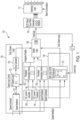
- a hoist application system 101 includes a motor drive unit 110, which is receptive of a final duty command and which drives a motor via switching logic 111 in accordance with the final duty command.
- the motor can be a BLDC motor and the motor drive unit 110 can be provided as a pulse width modulation (PWM) generation unit.
- the hoist application system 101 further includes a closed-loop control unit 120 that is configured to generate a closed-loop duty command, an open-loop control unit 130 that is configured to generate an open-loop duty command and a switch logic unit 140.
- the switch logic unit 140 is receptive of direct current (DC) system information, the closed-loop duty command from the closed-loop control unit 120 and the open-loop duty command from the open-loop control unit 130.
- the switch logic unit 140 is configured to generate the final duty command from one of the closed-loop duty command and the open-loop duty command based on the DC system information.
- the hoist application system 101 also includes a DC current calculator 150, which is configured to calculate DC-link current and to output a signal accordingly, a DC current threshold unit 151 that stores a predetermined threshold value of a DC current limit (i.e., about 150A) and a first comparator 152.
- the first comparator 152 is configured to compare the DC-link current and the predetermined threshold value, which together form the DC system information, to determine whether the DC-link current is currently above or below the predetermined threshold value and to issue a signal to the switch logic unit 140 accordingly.
- the hoist application system 101 still further includes a second comparator 153, which is receptive of a motor speed command signal (i.e., a commanded motor speed) and a motor speed feedback signal (i.e., a measured motor speed).
- the second comparator 153 is configured to compare the commanded motor speed and the measured motor speed, the determine which is larger and to issue a signal to the switch logic unit 140 accordingly.
- the closed-loop control unit 120 includes a summation unit 121, which is receptive of the motor speed command signal (i.e., the commanded motor speed) and the motor speed feedback signal (i.e., the measured motor speed), and which is configured to generate an error signal that is representative of the error between the commanded motor speed and the measured motor speed.
- the closed-loop control unit 120 further includes a proportional integral (PI) controller 122, which is receptive of the error signal that it converts to a PI voltage command signal, and a duty calculator 123.
- the duty calculator 123 is receptive of the PI voltage command signal and thus calculates the closed-loop duty command.
- the closed-loop duty command is calculated based at least partially on the error between a commanded motor speed and a measured motor speed.
- the PI controller 122 can be disabled by the switch logic unit 140 in a case in which the switch logic unit 140 generates the final duty command from the open-loop duty command.
- the open-loop control unit 130 includes a duty reducing unit 131, which is receptive of a current version of the final duty command, the motor speed feedback signal and the DC-link current.
- the open-loop control unit 130 is thus configured to calculate the open-loop duty command using a fuzzy map algorithm, which considers a measured motor speed from the motor speed feedback signal, the DC-link current from the DC system information and the current version of the final duty command.
- the open-loop control unit 130 can be configured to calculate the open-loop duty command to achieve a gradual time-based duty cycle reduction.
- the switch logic unit 140 is configured to transition from the closed-loop duty command to the open-loop duty command by comparing or recognizing the comparison of the first comparator 152 of the DC-link current to the predetermined threshold value (i.e., about 150A) and transitioning from the closed-loop duty command to the open-loop duty command in an event the DC-link current exceeds the predetermined threshold value for a predetermine time.
- the predetermined threshold value i.e., about 150A
- the switch logic unit 140 is configured to transition from the open-loop duty command to the closed-loop duty command in an event the comparison of the first and second comparators 152 and 153 indicate that the DC-link current is lower than the predetermined threshold value for a predetermined time and it is estimated whether, for the commanded motor speed and a load applied on the system, a closed-loop operation is possible without crossing the predetermined threshold value for the DC-link current. Based on an output of this estimation, the hoist application system 101 can transition to the closed-loop operation smoothly. In accordance with embodiments, the estimation can be carried out at a relatively slow rate so as to avoid unwanted switching between open-loop control to closed-loop control, which can result in system oscillation.
- a commanded motor speed can be set at 16,500 rpm.
- the motor is driven by the closed-loop duty command to 16,500 rpm, at which time a load on the motor is increased. This load increase continues until DC current reaches 150A.
- the open-loop duty command is used to drive the motor with the commanded (or reference) speed dropped to 10,000 rpm and then to 4,000 rpm without load reduction.
- the measured motor speed more closely follows the commanded motor speed than in the moments following the load increase and until the transition to the open-loop control.
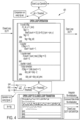
- a method 300 (see FIG. 3 ) of operating a hoist application system, such as the hoist application system 101 of FIG. 1 , is provided.
- the method 300 includes driving a motor in accordance with a final duty command (block 301), generating, in a closed-loop control unit, a closed-loop duty command (block 302) by calculating the closed-loop duty command based on the error between the commanded motor speed and the measured motor speed (block 3021), generating, in an open-loop control unit, an open-loop duty command (block 303) and generating the final duty command from one of the closed-loop duty command and the open-loop duty command based on DC system information (block 304).
- the generating of the open-loop duty command of block 303 can be executed using a fuzzy map algorithm as described above (block 3031) or to achieve a gradual time-based duty cycle reduction (block 3032).
- the generating of the final duty command of block 304 can includes switching from the closed-loop duty command to the open-loop duty command (block 305) or switching from the open-loop duty command to the closed-loop duty command (block 306).
- the switching from the closed-loop duty command to the open-loop duty command of block 305 includes comparing the DC-link current to the predetermined threshold value (i.e., about 150A) from the DC system information (block 3051) and transitioning from the closed-loop duty command to the open-loop duty command in an event the DC-link current exceeds the predetermined threshold value for the predetermine time (block 3052).
- the switching from the open-loop duty command to the closed-loop duty command of block 306 can include determining whether the DC system information indicates that the DC-link current is lower than the predetermined threshold value for the predetermined time and estimating whether, for the commanded motor speed and a load applied on the system, a closed-loop operation is possible without crossing the predetermined threshold value for the DC-link current (block 3061).
- the estimation can be carried out at a relatively slow rate to avoid unwanted switching between open-loop control to closed-loop control, which can result in system oscillation and, based on an output of this estimation, the hoist application system 101 can transition to the closed-loop operation smoothly.
- the switching from the open-loop duty command to the closed-loop duty command of block 306 can further include switching or transitioning from the open-loop duty command to the closed-loop duty command in an event the DC system information indicates that the DC-link current is lower than the predetermined threshold value for the DC-link current for the predetermined time and, for the commanded motor speed and a load applied on the system, it is estimated that the closed-loop operation is possible without crossing the predetermined threshold value for the DC-link current (block 3062).
- a state diagram 401 illustrating a hoist application system operation begins with closed-loop operation as described above. During the closed-loop operation, it is determined whether the DC current exceeds a threshold. If so, open-loop operation can be initiated as described above with the closed-loop duty cycle provided as an input and the open-loop duty cycle given as the output. During the open-loop operation, it is determined whether to return to closed-loop operation as explained above, or continue with the open-loop operation.
Landscapes
- Engineering & Computer Science (AREA)
- Power Engineering (AREA)
- Automation & Control Theory (AREA)
- Fuzzy Systems (AREA)
- Control Of Direct Current Motors (AREA)
Abstract
A hoist application system is provided. The hoist application system includes a motor drive unit (110), which is receptive of a final duty command and which drives a motor in accordance with the final duty command, a closed-loop control unit (120) configured to generate a closed-loop duty command, an open-loop control unit (130) configured to generate an open-loop duty command and a switch logic unit (140). The switch logic unit (140) is receptive of direct current (DC) system information, the closed-loop duty command and the open-loop duty command, and is configured to generate the final duty command from one of the closed-loop duty command and the open-loop duty command based on the DC system information.
Description
- This application claims the benefit of
Indian Application No. 202311020101 filed March 22, 2023 - The present disclosure relates to a hoist application and, in particular, to a current limit strategy for a hoist application.
- Helicopter-hoist equipment typically includes a lifting device such as a hoist, which is attached to a helicopter, a hoist cable and a hook located at the distal end of the cable for direct or indirect attachment to a person, animal or object for rescue. The hoist usually has a rotary drum and a motor. The motor turns the rotary drum for winding the cable in and out to lift or transport a load.
- A need remains for improved current control in a motor of helicopter-hoist equipment.
- According to an aspect of the disclosure, a hoist application system is provided. The hoist application system includes a motor drive unit, which is receptive of a final duty command and which drives a motor in accordance with the final duty command, a closed-loop control unit configured to generate a closed-loop duty command, an open-loop control unit configured to generate an open-loop duty command and a switch logic unit. The switch logic unit is receptive of direct current (DC) system information, the closed-loop duty command and the open-loop duty command, and is configured to generate the final duty command from one of the closed-loop duty command and the open-loop duty command based on the DC system information.
- In accordance with additional or alternative embodiments, the closed-loop control unit is configured to calculate the closed-loop duty command based on an error between a commanded motor speed and a measured motor speed.
- In accordance with additional or alternative embodiments, the open-loop control unit is configured to calculate the open-loop duty command using a fuzzy map algorithm.
- In accordance with additional or alternative embodiments, the fuzzy map algorithm considers a measured motor speed, the DC system information and a current version of the final duty command.
- In accordance with additional or alternative embodiments, the open-loop control unit is configured to calculate the open-loop duty command to achieve a gradual time-based duty cycle reduction.
- In accordance with additional or alternative embodiments, the switch logic unit is configured to transition from the closed-loop duty command to the open-loop duty command by comparing a DC-link current to a threshold value from the DC system information and transitioning from the closed-loop duty command to the open-loop duty command in an event the DC-link current exceeds the threshold value for a predetermine time.
- In accordance with additional or alternative embodiments, the threshold value is about 150A.
- In accordance with additional or alternative embodiments, the switch logic unit is configured to transition from the open-loop duty command to the closed-loop duty command in an event the DC system information indicates that a DC-link current is lower than a threshold value for a predetermined time and closed-loop operation is possible without crossing the threshold value.
- In accordance with additional or alternative embodiments, the threshold value is about 150A.
- According to an aspect of the disclosure, a method of operating a hoist application system is provided and includes driving a motor in accordance with a final duty command, generating, in a closed-loop control unit, a closed-loop duty command, generating, in an open-loop control unit, an open-loop duty command and generating the final duty command from one of the closed-loop duty command and the open-loop duty command based on direct current (DC) system information.
- In accordance with additional or alternative embodiments, the generating of the closed-loop duty command includes calculating the closed-loop duty command based on an error between a commanded motor speed and a measured motor speed.
- In accordance with additional or alternative embodiments, the generating of the open-loop duty command includes calculating the open-loop duty command using a fuzzy map algorithm.
- In accordance with additional or alternative embodiments, the fuzzy map algorithm considers a measured motor speed, the DC system information and a current version of the final duty command.
- In accordance with additional or alternative embodiments, the generating of the open-loop duty command includes calculating the open-loop duty command to achieve a gradual time-based duty cycle reduction.
- In accordance with additional or alternative embodiments, the generating of the final duty command includes switching from the closed-loop duty command to the open-loop duty command and the switching includes comparing a DC-link current to a threshold value from the DC system information and transitioning from the closed-loop duty command to the open-loop duty command in an event the DC-link current exceeds the threshold value for a predetermine time.
- In accordance with additional or alternative embodiments, the threshold value is about 150A.
- In accordance with additional or alternative embodiments, the generating of the final duty command includes switching from the open-loop duty command to the closed-loop duty command and the switching includes determining whether the DC system information indicates that a DC-link current is lower than a threshold value for a predetermined time and a closed-loop operation is possible without crossing the threshold value and switching from the open-loop duty command to the closed-loop duty command in an event the DC system information indicates that the DC-link current is lower than the threshold value for the predetermined time and, for a commanded motor speed and a load applied on the system, the closed-loop operation is possible without crossing the threshold value.
- In accordance with additional or alternative embodiments, the threshold value is about 150A.
- According to an aspect of the disclosure, a method of operating a hoist application system is provided and includes driving a motor in accordance with a final duty command, generating, in a closed-loop control unit, a closed-loop duty command, generating, in an open-loop control unit, an open-loop duty command and generating the final duty command from one of the closed-loop duty command and the open-loop duty command based on direct current (DC) system information. The generating of the final duty command includes one of switching from the closed-loop duty command to the open-loop duty command and switching from the open-loop duty command to the closed-loop duty command.
- In accordance with additional or alternative embodiments, the switching from the closed-loop duty command to the open-loop duty command includes comparing a DC-link current to a threshold value from the DC system information and transitioning from the closed-loop duty command to the open-loop duty command in an event the DC-link current exceeds the threshold value for a predetermine time and the switching from the open-loop duty command to the closed-loop duty command includes determining whether the DC system information indicates that a DC-link current is lower than a threshold value for a predetermined time and a closed-loop operation is possible without crossing the threshold value and switching from the open-loop duty command to the closed-loop duty command in an event the DC system information indicates that the DC-link current is lower than the threshold value for the predetermined time and, for a commanded motor speed and a load applied on the system, the closed-loop operation is possible without crossing the threshold value.
- Additional features and advantages are realized through the techniques of the present disclosure. Other embodiments and aspects of the disclosure are described in detail herein and are considered a part of the claimed technical concept. For a better understanding of the disclosure with the advantages and the features, refer to the description and to the drawings.
- For a more complete understanding of this disclosure, reference is now made to the following brief description, taken in connection with the accompanying drawings and detailed description, wherein like reference numerals represent like parts:
-
FIG. 1 is a schematic diagram illustrating a hoist application system in accordance with embodiments; -
FIG. 2 is a graphical illustrating of an execution of the hoist application system ofFIG. 1 in accordance with embodiments; -
FIG. 3 is a flow diagram illustrating a method of operating the hoist application system ofFIG. 1 in accordance with embodiments; and -
FIG. 4 is a state diagram illustrating a hoist application system operation in accordance with embodiments. - For specific applications of a brushless direct current (DC) or BLDC motor, such as in a hoist application for a helicopter, there is often a desire to control hoisting speed without a current loop. In these cases, a challenge exists in that monitoring and limiting DC-link current becomes necessary. Indeed, for certain BLDC motors with very low inductance, it can be difficult to control the input current. Moreover, in certain low-cost drive systems, there may not be three-phase current sensors available.
- Thus, as will be described below, a hoist application system is provided in which the DC-Link current is monitored and limited by taking a penalty on the speed of the motor in case of high loads. Typically, a hysteresis controller for the DC-link current can be used, but this will result in speed oscillations if it is not implemented with a high accuracy sensor or with a reduced latency system. To avoid this issue, a logical architecture is configured to smoothly transition from closed-loop speed control to an open-loop duty cycle-based motor drive system and vice versa. In the open-loop system, a calculated duty cycle is applied to limit the DC-link current based on speed and current feedback.
- With reference to
FIG. 1 , ahoist application system 101 is provided and includes amotor drive unit 110, which is receptive of a final duty command and which drives a motor viaswitching logic 111 in accordance with the final duty command. The motor can be a BLDC motor and themotor drive unit 110 can be provided as a pulse width modulation (PWM) generation unit. Thehoist application system 101 further includes a closed-loop control unit 120 that is configured to generate a closed-loop duty command, an open-loop control unit 130 that is configured to generate an open-loop duty command and aswitch logic unit 140. Theswitch logic unit 140 is receptive of direct current (DC) system information, the closed-loop duty command from the closed-loop control unit 120 and the open-loop duty command from the open-loop control unit 130. Theswitch logic unit 140 is configured to generate the final duty command from one of the closed-loop duty command and the open-loop duty command based on the DC system information. - In addition, the
hoist application system 101 also includes a DCcurrent calculator 150, which is configured to calculate DC-link current and to output a signal accordingly, a DCcurrent threshold unit 151 that stores a predetermined threshold value of a DC current limit (i.e., about 150A) and afirst comparator 152. Thefirst comparator 152 is configured to compare the DC-link current and the predetermined threshold value, which together form the DC system information, to determine whether the DC-link current is currently above or below the predetermined threshold value and to issue a signal to theswitch logic unit 140 accordingly. Thehoist application system 101 still further includes asecond comparator 153, which is receptive of a motor speed command signal (i.e., a commanded motor speed) and a motor speed feedback signal (i.e., a measured motor speed). Thesecond comparator 153 is configured to compare the commanded motor speed and the measured motor speed, the determine which is larger and to issue a signal to theswitch logic unit 140 accordingly. - The closed-
loop control unit 120 includes asummation unit 121, which is receptive of the motor speed command signal (i.e., the commanded motor speed) and the motor speed feedback signal (i.e., the measured motor speed), and which is configured to generate an error signal that is representative of the error between the commanded motor speed and the measured motor speed. The closed-loop control unit 120 further includes a proportional integral (PI)controller 122, which is receptive of the error signal that it converts to a PI voltage command signal, and aduty calculator 123. Theduty calculator 123 is receptive of the PI voltage command signal and thus calculates the closed-loop duty command. Thus, the closed-loop duty command is calculated based at least partially on the error between a commanded motor speed and a measured motor speed. ThePI controller 122 can be disabled by theswitch logic unit 140 in a case in which theswitch logic unit 140 generates the final duty command from the open-loop duty command. - The open-
loop control unit 130 includes aduty reducing unit 131, which is receptive of a current version of the final duty command, the motor speed feedback signal and the DC-link current. The open-loop control unit 130 is thus configured to calculate the open-loop duty command using a fuzzy map algorithm, which considers a measured motor speed from the motor speed feedback signal, the DC-link current from the DC system information and the current version of the final duty command. Alternatively, the open-loop control unit 130 can be configured to calculate the open-loop duty command to achieve a gradual time-based duty cycle reduction. - With the hoist
application system 101 configured as described above, theswitch logic unit 140 is configured to transition from the closed-loop duty command to the open-loop duty command by comparing or recognizing the comparison of thefirst comparator 152 of the DC-link current to the predetermined threshold value (i.e., about 150A) and transitioning from the closed-loop duty command to the open-loop duty command in an event the DC-link current exceeds the predetermined threshold value for a predetermine time. Conversely, theswitch logic unit 140 is configured to transition from the open-loop duty command to the closed-loop duty command in an event the comparison of the first andsecond comparators application system 101 can transition to the closed-loop operation smoothly. In accordance with embodiments, the estimation can be carried out at a relatively slow rate so as to avoid unwanted switching between open-loop control to closed-loop control, which can result in system oscillation. - An operation of the hoist
application system 101 is illustrated inFIG. 2 . As shown inFIG. 2 , a commanded motor speed can be set at 16,500 rpm. In this case, the motor is driven by the closed-loop duty command to 16,500 rpm, at which time a load on the motor is increased. This load increase continues until DC current reaches 150A. At this point, the open-loop duty command is used to drive the motor with the commanded (or reference) speed dropped to 10,000 rpm and then to 4,000 rpm without load reduction. During the use of the open-loop duty command, it is observed that the measured motor speed more closely follows the commanded motor speed than in the moments following the load increase and until the transition to the open-loop control. - With reference to
FIGS. 3 and4 , a method 300 (seeFIG. 3 ) of operating a hoist application system, such as the hoistapplication system 101 ofFIG. 1 , is provided. The method 300 includes driving a motor in accordance with a final duty command (block 301), generating, in a closed-loop control unit, a closed-loop duty command (block 302) by calculating the closed-loop duty command based on the error between the commanded motor speed and the measured motor speed (block 3021), generating, in an open-loop control unit, an open-loop duty command (block 303) and generating the final duty command from one of the closed-loop duty command and the open-loop duty command based on DC system information (block 304). The generating of the open-loop duty command ofblock 303 can be executed using a fuzzy map algorithm as described above (block 3031) or to achieve a gradual time-based duty cycle reduction (block 3032). - The generating of the final duty command of
block 304 can includes switching from the closed-loop duty command to the open-loop duty command (block 305) or switching from the open-loop duty command to the closed-loop duty command (block 306). The switching from the closed-loop duty command to the open-loop duty command ofblock 305 includes comparing the DC-link current to the predetermined threshold value (i.e., about 150A) from the DC system information (block 3051) and transitioning from the closed-loop duty command to the open-loop duty command in an event the DC-link current exceeds the predetermined threshold value for the predetermine time (block 3052). - The switching from the open-loop duty command to the closed-loop duty command of
block 306 can include determining whether the DC system information indicates that the DC-link current is lower than the predetermined threshold value for the predetermined time and estimating whether, for the commanded motor speed and a load applied on the system, a closed-loop operation is possible without crossing the predetermined threshold value for the DC-link current (block 3061). In accordance with embodiments, the estimation can be carried out at a relatively slow rate to avoid unwanted switching between open-loop control to closed-loop control, which can result in system oscillation and, based on an output of this estimation, the hoistapplication system 101 can transition to the closed-loop operation smoothly. That is, the switching from the open-loop duty command to the closed-loop duty command ofblock 306 can further include switching or transitioning from the open-loop duty command to the closed-loop duty command in an event the DC system information indicates that the DC-link current is lower than the predetermined threshold value for the DC-link current for the predetermined time and, for the commanded motor speed and a load applied on the system, it is estimated that the closed-loop operation is possible without crossing the predetermined threshold value for the DC-link current (block 3062). - As shown in
FIG. 4 , a state diagram 401 illustrating a hoist application system operation is provided. The state diagram begins with closed-loop operation as described above. During the closed-loop operation, it is determined whether the DC current exceeds a threshold. If so, open-loop operation can be initiated as described above with the closed-loop duty cycle provided as an input and the open-loop duty cycle given as the output. During the open-loop operation, it is determined whether to return to closed-loop operation as explained above, or continue with the open-loop operation. - Technical effects and benefits of the present disclosure are the provision of a hoist application system that is low cost and has a relatively simple control algorithm.
- The corresponding structures, materials, acts, and equivalents of all means or step-plus function elements in the claims below are intended to include any structure, material, or act for performing the function in combination with other claimed elements as specifically claimed. The description of the present disclosure has been presented for purposes of illustration and description, but is not intended to be exhaustive or limited to the technical concepts in the form disclosed. Many modifications and variations will be apparent to those of ordinary skill in the art without departing from the scope and spirit of the disclosure. The embodiments were chosen and described in order to best explain the principles of the disclosure and the practical application, and to enable others of ordinary skill in the art to understand the disclosure for various embodiments with various modifications as are suited to the particular use contemplated.
- While the preferred embodiments to the disclosure have been described, it will be understood that those skilled in the art, both now and in the future, may make various improvements and enhancements which fall within the scope of the claims which follow. These claims should be construed to maintain the proper protection for the disclosure first described.
Claims (15)
- A hoist application system, comprising:a motor drive unit (110), which is receptive of a final duty command and which drives a motor in accordance with the final duty command;a closed-loop control unit (120) configured to generate a closed-loop duty command;an open-loop control unit (130) configured to generate an open-loop duty command; anda switch logic unit (140), which is receptive of direct current (DC) system information, the closed-loop duty command and the open-loop duty command, and which is configured to generate the final duty command from one of the closed-loop duty command and the open-loop duty command based on the DC system information.
- The hoist application system according to claim 1, wherein the closed-loop control unit (120) is configured to calculate the closed-loop duty command based on an error between a commanded motor speed and a measured motor speed.
- The hoist application system according to claim 1 or 2, wherein the open-loop control unit (130) is configured to calculate the open-loop duty command using a fuzzy map algorithm, and optionally wherein the fuzzy map algorithm considers a measured motor speed, the DC system information and a current version of the final duty command.
- The hoist application system according to any preceding claim, wherein the open-loop control unit (130) is configured to calculate the open-loop duty command to achieve a gradual time-based duty cycle reduction.
- The hoist application system according to claim 1, wherein the switch logic unit (140) is configured to transition from the closed-loop duty command to the open-loop duty command by comparing a DC-link current to a threshold value from the DC system information and transitioning from the closed-loop duty command to the open-loop duty command in an event the DC-link current exceeds the threshold value for a predetermine time, and optionally wherein the threshold value is about 150A.
- The hoist application system according to any preceding claim, wherein the switch logic unit (140) is configured to transition from the open-loop duty command to the closed-loop duty command in an event the DC system information indicates that a DC-link current is lower than a threshold value for a predetermined time and closed-loop operation is possible without crossing the threshold value.
- The hoist application system according to claim 5, wherein the threshold value is about 150A.
- A method of operating a hoist application system, the method comprising:driving a motor in accordance with a final duty command;generating, in a closed-loop control unit (120), a closed-loop duty command;generating, in an open-loop control unit (130), an open-loop duty command; andgenerating the final duty command from one of the closed-loop duty command and the open-loop duty command based on direct current (DC) system information.
- The method according to claim 8, wherein the generating of the closed-loop duty command comprises calculating the closed-loop duty command based on an error between a commanded motor speed and a measured motor speed.
- The method according to claim 8 or 9, wherein the generating of the open-loop duty command comprises calculating the open-loop duty command using a fuzzy map algorithm, and optionally wherein the fuzzy map algorithm considers a measured motor speed, the DC system information and a current version of the final duty command.
- The method according to any of claims 8 to 10, wherein the generating of the open-loop duty command comprises calculating the open-loop duty command to achieve a gradual time-based duty cycle reduction.
- The method according to any of claims 8 to 11, wherein:the generating of the final duty command comprises switching from the closed-loop duty command to the open-loop duty command, andthe switching comprises:comparing a DC-link current to a threshold value from the DC system information; andtransitioning from the closed-loop duty command to the open-loop duty command in an event the DC-link current exceeds the threshold value for a predetermine time, and optionally wherein the threshold value is about 150A.
- The method according to any of claims 8 to 12, wherein:the generating of the final duty command comprises switching from the open-loop duty command to the closed-loop duty command, andthe switching comprises:determining whether the DC system information indicates that a DC-link current is lower than a threshold value for a predetermined time and a closed-loop operation is possible without crossing the threshold value; andswitching from the open-loop duty command to the closed-loop duty command in an event the DC system information indicates that the DC-link current is lower than the threshold value for the predetermined time and, for a commanded motor speed and a load applied on the system, the closed-loop operation is possible without crossing the threshold value, and optionally wherein the threshold value is about 150A.
- A method of operating a hoist application system, the method comprising:driving a motor in accordance with a final duty command;generating, in a closed-loop control unit (120), a closed-loop duty command;generating, in an open-loop control unit (130), an open-loop duty command; andgenerating the final duty command from one of the closed-loop duty command and the open-loop duty command based on direct current (DC) system information,wherein the generating of the final duty command comprises one of switching from the closed-loop duty command to the open-loop duty command and switching from the open-loop duty command to the closed-loop duty command.
- The method according to claim 14, wherein:the switching from the closed-loop duty command to the open-loop duty command comprises comparing a DC-link current to a threshold value from the DC system information and transitioning from the closed-loop duty command to the open-loop duty command in an event the DC-link current exceeds the threshold value for a predetermine time, andthe switching from the open-loop duty command to the closed-loop duty command comprises determining whether the DC system information indicates that a DC-link current is lower than a threshold value for a predetermined time and a closed-loop operation is possible without crossing the threshold value and switching from the open-loop duty command to the closed-loop duty command in an event the DC system information indicates that the DC-link current is lower than the threshold value for the predetermined time and, for a commanded motor speed and a load applied on the system, the closed-loop operation is possible without crossing the threshold value.
Applications Claiming Priority (1)
| Application Number | Priority Date | Filing Date | Title |
|---|---|---|---|
| IN202311020101 | 2023-03-22 |
Publications (1)
| Publication Number | Publication Date |
|---|---|
| EP4436031A1 true EP4436031A1 (en) | 2024-09-25 |
Family
ID=90417666
Family Applications (1)
| Application Number | Title | Priority Date | Filing Date |
|---|---|---|---|
| EP24165276.7A Pending EP4436031A1 (en) | 2023-03-22 | 2024-03-21 | Novel current limit strategy for hoist application |
Country Status (3)
| Country | Link |
|---|---|
| US (1) | US12407286B2 (en) |
| EP (1) | EP4436031A1 (en) |
| CA (1) | CA3232513A1 (en) |
Citations (3)
| Publication number | Priority date | Publication date | Assignee | Title |
|---|---|---|---|---|
| US20070115899A1 (en) * | 2005-11-22 | 2007-05-24 | Shlomo Ovadia | Method, apparatus and system architecture for performing handovers between heterogeneous wireless networks |
| WO2015179364A2 (en) * | 2014-05-19 | 2015-11-26 | Black & Decker Inc. | Cycle-by-cycle current limit for power tools having a brushless motor |
| CN110963380A (en) * | 2019-12-27 | 2020-04-07 | 重庆威斯特电梯有限公司 | Elevator controller, elevator and elevator control method |
Family Cites Families (23)
| Publication number | Priority date | Publication date | Assignee | Title |
|---|---|---|---|---|
| US4665350A (en) | 1986-01-31 | 1987-05-12 | General Motors Corporation | Open-loop brushless motor control system |
| WO2002010984A2 (en) | 2000-07-21 | 2002-02-07 | Triplehop Technologies, Inc. | System and method for obtaining user preferences and providing user recommendations for unseen physical and information goods and services |
| DE60135149D1 (en) | 2000-12-30 | 2008-09-11 | Hamilton Sundstrand Corp | SWITCH CONTROL SYSTEM AND SPEED CONTROL FOR A BRUSHLESS ENGINE |
| US6803735B2 (en) | 2002-10-01 | 2004-10-12 | Siemens Vdo Automotive Inc. | Speed-based open-loop start-up method for brushless DC motor |
| US6801009B2 (en) | 2002-11-27 | 2004-10-05 | Siemens Vdo Automotive Inc. | Current limitation process of brush and brushless DC motors during severe voltage changes |
| US7145302B2 (en) | 2004-04-06 | 2006-12-05 | General Electric Company | Method and apparatus for driving a brushless direct current motor |
| US6975087B1 (en) * | 2004-08-06 | 2005-12-13 | Delphi Technologies, Inc. | Closed-loop control system |
| US7321210B2 (en) | 2005-04-05 | 2008-01-22 | International Rectifier Corporation | Sensorless brushless direct current motor drive using pulse width modulation speed control at motor frequency |
| EP2377237A4 (en) | 2008-12-17 | 2017-10-25 | LG Electronics Inc. | Apparatus and method for start-up of a sensorless bldc motor |
| CN102355179A (en) | 2011-09-22 | 2012-02-15 | 西北工业大学 | Device and method for carrying out cooperative control on multiple brushless DC (direct current) motors |
| KR101366772B1 (en) * | 2012-09-24 | 2014-02-26 | 삼성전기주식회사 | Motor driving device, and method for cotrolling motor |
| US9444376B2 (en) | 2013-02-22 | 2016-09-13 | Hamilton Sundstrand Corporation | Variable link sensorless brushless direct current motor controller for space and hardened applications |
| DE102013003513A1 (en) | 2013-03-04 | 2014-09-04 | Wabco Gmbh | Compressor arrangement for operating a compressed air supply system, compressed air supply system and compressed air supply system and vehicle with such a compressed air supply system |
| CN104155877A (en) | 2014-08-19 | 2014-11-19 | 江苏科技大学 | Brushless DC motor fuzzy control system based on genetic algorithm and control method thereof |
| US9374028B2 (en) * | 2014-08-22 | 2016-06-21 | Rockwell Automation Technologies, Inc. | Transition scheme for position sensorless control of AC motor drives |
| US10284129B2 (en) | 2015-09-16 | 2019-05-07 | Eaton Intelligent Power Limited | Three-phase variable reference pulse width modulation |
| US9960669B2 (en) * | 2016-03-21 | 2018-05-01 | Analog Devices, Inc. | Hybrid soft-start for isolated converter |
| US10050574B2 (en) | 2016-05-06 | 2018-08-14 | The Boeing Company | Management of motor regeneration |
| US10074245B2 (en) | 2017-01-10 | 2018-09-11 | Woodward, Inc. | Force feel using a brushless DC motor |
| US10501293B2 (en) | 2017-01-31 | 2019-12-10 | Goodrich Aerospace Services Private Limited | Method of applying brake to a hoist by electromagnetic means in a permanent magnet motor |
| US10870562B2 (en) | 2017-07-11 | 2020-12-22 | Goodrich Corporation | System and method for hoist with integrated drum and motor |
| JP2020115713A (en) | 2019-01-17 | 2020-07-30 | 日本電産モビリティ株式会社 | Motor control device |
| US11764710B2 (en) * | 2021-06-30 | 2023-09-19 | Texas Instruments Incorporated | Automatic transition of motor controller from open-loop control to closed-loop control |
-
2023
- 2023-07-21 US US18/356,334 patent/US12407286B2/en active Active
-
2024
- 2024-03-19 CA CA3232513A patent/CA3232513A1/en active Pending
- 2024-03-21 EP EP24165276.7A patent/EP4436031A1/en active Pending
Patent Citations (3)
| Publication number | Priority date | Publication date | Assignee | Title |
|---|---|---|---|---|
| US20070115899A1 (en) * | 2005-11-22 | 2007-05-24 | Shlomo Ovadia | Method, apparatus and system architecture for performing handovers between heterogeneous wireless networks |
| WO2015179364A2 (en) * | 2014-05-19 | 2015-11-26 | Black & Decker Inc. | Cycle-by-cycle current limit for power tools having a brushless motor |
| CN110963380A (en) * | 2019-12-27 | 2020-04-07 | 重庆威斯特电梯有限公司 | Elevator controller, elevator and elevator control method |
Also Published As
| Publication number | Publication date |
|---|---|
| CA3232513A1 (en) | 2025-06-25 |
| US20240322723A1 (en) | 2024-09-26 |
| US12407286B2 (en) | 2025-09-02 |
Similar Documents
| Publication | Publication Date | Title |
|---|---|---|
| CN101910524B (en) | Hybrid construction machine and control method for hybrid construction machine | |
| EP1729407B1 (en) | Controller of permanent magnet synchronous motor | |
| US8348020B2 (en) | Elevator control device with carrier frequency switch circuit | |
| EP2888190B1 (en) | Elevator system using dynamic braking | |
| CN111211715B (en) | A motor control method, system, and controller | |
| US10128776B2 (en) | Inverter device | |
| JP5808779B2 (en) | Excavator | |
| JP5476681B2 (en) | Elevator system motor controller | |
| JP4786942B2 (en) | Inverter device | |
| US7588125B2 (en) | Elevator control device | |
| JP6169936B2 (en) | Inverter device | |
| US12407286B2 (en) | Current limit strategy for hoist application | |
| EP1695861B1 (en) | Forklift and method for controlling induction motor applied to the same | |
| CN108352798B (en) | Motor control device and elevator using the same | |
| JP7732582B2 (en) | Elevator door control device | |
| JP5654770B2 (en) | Automatic door drive control device | |
| KR102216667B1 (en) | Apparatus and Method for controlling power source abnormality of motor | |
| JPH07111708A (en) | Induction motor controller for electric vehicle | |
| BR102024005488A2 (en) | WINCH APPLICATION SYSTEM, AND, METHOD OF OPERATION OF A WINCH APPLICATION SYSTEM | |
| JPH11246182A (en) | Inverter-controlled crane / hoist light-load booster | |
| JP5399789B2 (en) | Inverter device and teaching method for inverter device | |
| JP7639958B1 (en) | Motor control device | |
| KR20080016373A (en) | Inertial load suppression device and method for inverter system | |
| KR100709816B1 (en) | Control device of permanent magnet synchronous motor | |
| CN108934185B (en) | Inverter device and method for determining light load of motor |
Legal Events
| Date | Code | Title | Description |
|---|---|---|---|
| PUAI | Public reference made under article 153(3) epc to a published international application that has entered the european phase |
Free format text: ORIGINAL CODE: 0009012 |
|
| STAA | Information on the status of an ep patent application or granted ep patent |
Free format text: STATUS: THE APPLICATION HAS BEEN PUBLISHED |
|
| AK | Designated contracting states |
Kind code of ref document: A1 Designated state(s): AL AT BE BG CH CY CZ DE DK EE ES FI FR GB GR HR HU IE IS IT LI LT LU LV MC ME MK MT NL NO PL PT RO RS SE SI SK SM TR |
|
| STAA | Information on the status of an ep patent application or granted ep patent |
Free format text: STATUS: REQUEST FOR EXAMINATION WAS MADE |
|
| 17P | Request for examination filed |
Effective date: 20250325 |