EP4435989A1 - Electrical protection circuit for energy storage unit - Google Patents
Electrical protection circuit for energy storage unit Download PDFInfo
- Publication number
- EP4435989A1 EP4435989A1 EP23169650.1A EP23169650A EP4435989A1 EP 4435989 A1 EP4435989 A1 EP 4435989A1 EP 23169650 A EP23169650 A EP 23169650A EP 4435989 A1 EP4435989 A1 EP 4435989A1
- Authority
- EP
- European Patent Office
- Prior art keywords
- switch
- esu
- electrical protection
- power line
- discharging
- Prior art date
- Legal status (The legal status is an assumption and is not a legal conclusion. Google has not performed a legal analysis and makes no representation as to the accuracy of the status listed.)
- Pending
Links
Images





Classifications
-
- H—ELECTRICITY
- H02—GENERATION; CONVERSION OR DISTRIBUTION OF ELECTRIC POWER
- H02H—EMERGENCY PROTECTIVE CIRCUIT ARRANGEMENTS
- H02H7/00—Emergency protective circuit arrangements specially adapted for specific types of electric machines or apparatus or for sectionalised protection of cable or line systems, and effecting automatic switching in the event of an undesired change from normal working conditions
- H02H7/18—Emergency protective circuit arrangements specially adapted for specific types of electric machines or apparatus or for sectionalised protection of cable or line systems, and effecting automatic switching in the event of an undesired change from normal working conditions for batteries; for accumulators
-
- H—ELECTRICITY
- H02—GENERATION; CONVERSION OR DISTRIBUTION OF ELECTRIC POWER
- H02J—ELECTRIC POWER NETWORKS; CIRCUIT ARRANGEMENTS OR SYSTEMS FOR SUPPLYING OR DISTRIBUTING ELECTRIC POWER; SYSTEMS FOR STORING ELECTRIC ENERGY
- H02J7/00—Circuit arrangements for charging or discharging batteries or for supplying loads from batteries
- H02J7/60—Circuit arrangements for charging or discharging batteries or for supplying loads from batteries including safety or protection arrangements
- H02J7/62—Circuit arrangements for charging or discharging batteries or for supplying loads from batteries including safety or protection arrangements against overcurrent
-
- H—ELECTRICITY
- H02—GENERATION; CONVERSION OR DISTRIBUTION OF ELECTRIC POWER
- H02J—ELECTRIC POWER NETWORKS; CIRCUIT ARRANGEMENTS OR SYSTEMS FOR SUPPLYING OR DISTRIBUTING ELECTRIC POWER; SYSTEMS FOR STORING ELECTRIC ENERGY
- H02J7/00—Circuit arrangements for charging or discharging batteries or for supplying loads from batteries
- H02J7/60—Circuit arrangements for charging or discharging batteries or for supplying loads from batteries including safety or protection arrangements
Definitions
- the present disclosure generally relates to energy storage units. More particularly, it relates to providing an electrical protection circuit for an energy storage unit, ESU.
- an energy storage sector consists of several different branches of mediums/energy storage units, ESUs, to store energy.
- the ESUs include batteries, supercapacitors, or the like.
- a fault condition for example, current overloading, rapid discharge, under voltage, or the like
- the ESUs have to be protected.
- An electrical protection circuit can be used to protect an ESU.
- the protection circuit can implement a method of electrical protection for protecting the ESU.
- the ESU behaves differently depending on an implemented method of electrical protection.
- consequences such as thermal runaway, arcing, venting, fire, or the like, can cause short-circuit.
- the electrical system may have an open circuit, which can cause very high over-voltage.
- an electrical protection circuit for connecting an energy storage unit, ESU, to a main power line.
- the electrical protection circuit comprises a first main terminal configured to be connected to the main power line, a second main terminal configured to be connected to the main power line, wherein the second main terminal is configured for a lower electric potential than the first main terminal.
- the first ESU terminal configured to be connected to a positive terminal of the ESU and a second ESU terminal configured to be connected to a negative terminal of the ESU.
- the first main terminal is connected to the first ESU terminal via a first normally closed, NC, switch.
- the electrical protection circuit comprises a first diode with an anode connected to the first main terminal and a cathode connected to the first ESU terminal.
- a parallel combination of the first NC switch and the first diode forms a closed path for a charging current and a discharging current flowing between the main power line and the ESU during operation.
- the first main terminal is connected to the second main terminal via a normally open, NO, switch, and a second diode being connected in parallel with the NO switch with a cathode connected to the first main terminal, and an anode connected to the second main terminal.
- the first NC switch is configured to be opened thereby to disconnect the ESU from the main power line.
- the NO switch is configured to be closed thereby to bypass the ESU from the main power line in order to achieve electrical protection for the ESU.
- controllable and safe electrical protection circuit which combines disconnection and bypassing functionalities for providing electrical protection to the ESU.
- the electrical protection circuit comprises a discharging circuit.
- the discharging circuit comprises a resistor in series with a discharging switch.
- the discharging circuit is connected between the first ESU terminal and the second ESU terminal.
- the discharging switch is a NO switch.
- the discharging switch is configured to be closed thereby to discharge the ESU through the resistor in order to achieve the electrical protection for the ESU.
- the proposed electrical protection circuit utilizes discharging functionality along with the disconnection and bypassing functionalities for providing electrical protection to the ESU.
- the electrical protection circuit disclosed herein may act as universal protection circuit, as the combined functionalities (disconnection, bypassing, and discharging) of the electrical protection circuit may be applicable for all types of ESUs.
- the electrical protection circuit may provide electrical protection for both battery unit and supercapacitor (exemplary types of the ESUs).
- the usage of the electrical protection circuit disclosed herein for electrically protecting the ESU may increase reliability.
- the electrical protection circuit disclosed herein may comprise small sized and less expensive components.
- the electrical protection circuit disclosed herein may be used for different levels, availability of an Energy Storage, ES, system comprising the ESU may be increased.
- the electrical protection circuit further comprises a second NC switch connected in series with the first NC switch.
- the second NC switch is configured to disconnect the ESU and the discharging circuit from the main power line thereby achieving electrical protection for the ESU.
- the electrical protection circuit further comprises a third NC switch connected in series with the ESU.
- the third NC switch is configured to disconnect the ESU from the discharging circuit and the main power line thereby achieving electrical protection for the ESU.
- the electrical protection circuit further comprises a second NC switch connected in series with the first NC switch and a third NC switch connected in series with the ESU.
- a combination of the second NC switch and the third NC switch is configured to disconnect the ESU and the discharging circuit from the main power line thereby achieving electrical protection for the ESU.
- the second NC switch is configured to be opened to disconnect the ESU and the discharging circuit from the main power line
- the third NC switch is configured to be opened after opening of the second NC switch and after discharging of the ESU through the resistor, thereby achieving electrical protection for the ESU.
- the third NC switch is configured to be opened after discharging of the ESU through the resistor and the second NC switch is configured to be opened after opening of the third NC switch, thereby achieving electrical protection for the ESU.
- the electrical protection circuit further comprises a resistor connected in parallel to the first NC switch, wherein the closing of the NO switch causes the ESU to discharge through the resistor thereby achieving electrical protection for the ESU.
- the electrical protection circuit further comprises a resistor connected in parallel to the first NC switch and a second NC switch connected in between the ESU and the parallel combination of the resistor and the first NC switch.
- the first NC switch connected in parallel to the resistor is configured to be opened for causing the charging current to flow through the first diode or the second diode
- the NO switch is configured to be closed for discharging the ESU
- the second NC switch connected in between the ESU and the parallel combination of the resistor and the first NC switch is configured to be opened for disconnecting the ESU from the main power line, when the ESU is discharged.
- the first NC switch, the second NC switch, the third NC switch, the NO switch, and the discharging switch are of same or different types and connectable in series or parallel configuration.
- the ESU is at least one of a battery unit or a supercapacitor.
- the electrical protection circuit is configured to maintain uninterrupted current flow for rest of system other than the ESU during the bypassing.
- a method for connecting an Energy Storage Unit, ESU, to a main power line comprises opening a first normally closed, NC, switch to disconnect the ESU from a main power line.
- a parallel combination of the first NC switch and a first diode forms a closed path for charging current and a discharging current flowing between the main power line and the ESU during operation.
- Opening the first NC switch causes the charging current to flow from the main power line to the ESU through a first diode.
- Opening the first NC switch causes the discharging current to flow to the main line through a second diode being connected in parallel with a normally open, NO, switch, thereby disconnecting the ESU.
- the method comprises closing the NO switch to bypass current flowing through the ESU.
- Closing the NO switch causes the charging current and the discharging current to get diverted to least resistance path provided by the parallel combination of the closed NO switch and the second diode thereby bypassing the ESU.
- the electrical protection is provided to the ESU by opening the first NC switch to disconnect the ESU from the main power line and by closing the NO switch to bypass the ESU from the main power line.
- the method comprises closing a discharging switch to discharge the ESU through a resistor to provide the electrical protection to the ESU.
- the resistor is in series with the discharging switch, wherein the discharging switch is another NO switch.
- the ESU may be protected by combining disconnection, bypassing and discharging functionalities.
- a module for connecting an Energy Storage Unit, ESU, to a main power line comprises a first main terminal configured to be connected to the main power line.
- the module comprises a second main terminal configured to be connected to the main power line, wherein the second main terminal is configured for a lower electric potential than the first main terminal.
- the module comprises a first ESU terminal configured to be connected to a positive terminal of the ESU.
- the module comprises a second ESU terminal configured to be connected to a negative terminal of the ESU.
- the module comprises an electrical protection circuit according to the first aspect of the present disclosure..
- Fig. 1 discloses an electrical protection circuit 100 for an Energy Storage Unit, ESU 10.
- the electrical protection circuit 100 referred herein is configured for providing electrical protection to the ESU 10.
- the electrical protection may be provided to the ESU 10 in an event of one or more fault conditions such as, but not limited to, current overloading, rapid discharge, under voltage, or the like.
- the ESU 10 may comprise one or more of: a battery unit, a supercapacitor, or the like.
- the electrical protection circuit may implement a method of electrical protection for protecting the ESU 10.
- the ESU 10 behaves differently depending on an implemented method of electrical protection.
- different types of electrical protection circuits can be used, as the electrical protection circuit may not implement a single method of electrical protection for the different types of ESUs.
- controllable, safe, and universal electrical protection circuit 100 is provided for providing electrical protection to the ESU 10.
- the electrical protection circuit 100 connects the ESU 10 to the main power line 80.
- the electrical protection circuit 100 comprises a first main terminal, a second main terminal, a first ESU terminal, a second ESU terminal, a first normally closed, NC, switch 20, a first diode 30, a normally open, NO, switch 40, and a second diode 50.
- the first main terminal and the second main terminal are configured to be connected to the main power line 80.
- the second main terminal is configured for a lower electric potential than the first main terminal.
- the first ESU terminal is configured to be connected to a positive terminal of the ESU 10.
- the second ESU terminal is configured to be connected to a negative terminal of the ESU 10.
- the first main terminal is connected to the first ESU terminal via the first NC switch 20.
- An anode of the first diode 30 is connected to the first main terminal and a cathode of the first diode 30 is connected to the first ESU terminal.
- a parallel combination of the first NC switch 20 and the first diode 30 forms a closed path for a charging current and a discharging current flowing between the main power line 80 and the ESU 10 during operation.
- the first main terminal is connected to the second main terminal via the NO switch 40 and the second diode 50.
- the second diode 50 is connected in parallel with the NO switch 40 with a cathode connected to the first main terminal and an anode connected to the second main terminal.
- the first NC switch 20, and the NO switch 40 may be of same or different types and connectable in series or parallel configuration.
- Examples of the switch may include, but are not limited to, a mechanical switch, an electro-mechanical switch, a Silicon based switch, a Wide bandgap, WBG, based semiconductor switch, a pyrotechnical switch, an electron tube, or a combination thereof. As would be understood, any similar type of above described switch may be considered herein.
- the first NC switch 20 is configured to be opened thereby to disconnect the ESU 10 from the main power line 80.
- the NO switch 40 is configured to be closed thereby to bypass the ESU 10 from the main power line 80. Thereby, achieving electrical protection for the ESU 10.
- Opening of the first NC switch 20 causes the charging current to flow from the main power line 80 to the ESU 10 through the first diode 30 and causes the discharging current to flow to the main power line 80 through the second diode 50. Thereby disconnecting the ESU 10 from the main power line 80.
- Closing of the NO switch causes the charging current and the discharging current to be diverted to at least resistance path provided by the parallel combination of the closed NO switch 40 and the second diode 50. Thereby, bypassing the ESU 10.
- the electrical protection circuit 100 may be configured to maintain uninterrupted current flow for rest of system other than the ESU 10.
- the system referred herein may be an electrical system/Energy Storage, ES, system comprising the ESU 10.
- the electrical protection circuit 100 disclosed herein utilizes disconnection and bypassing functionality/protection methods for protecting the ESU 10 electrically.
- the electrical protection circuit 100 may further comprise a discharging circuit.
- the discharging circuit may comprise a resistor 60 in series with a discharging switch 70.
- the discharging circuit may be connected between the first ESU terminal and the second ESU terminal.
- the discharging switch 70 may be another NO switch.
- the discharging switch 70 may be of different types and may be connected in series or parallel configuration. Examples of the switch may include, but are not limited to, a mechanical switch, an electro-mechanical switch, a Silicon based switch, a WBG semiconductor switch, a pyrotechnical switch, an electron tube, or a combination thereof.
- the discharging switch 70 may be configured to be closed thereby to discharge the ESU 10 through the resistor 60 in order to achieve the electrical protection for the ESU 10. In some examples, the discharging of the ESU 10 may be carried out for a long period of time (for example, hours/days).
- discharging functionality may also be combined with the disconnection and bypassing functionality for providing the electrical protection to the ESU 10.
- the electrical protection circuit 100 may be designed for the both the battery unit and the supercapacitor (i.e., for any type of ESUs 10). However, it should be noted that an arrangement of the components of the electrical protection unit 100 may be differed for each type of the ESU 10.
- the electrical protection circuit 100 may comprise an over voltage protection for switches such as the first NC switch 20, and the NO switch 40.
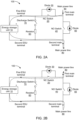
- Figs. 2A and 2B disclose the electrical protection circuit 100 configured to connect the ESU 10 to the main power line 80 and protect the ESU 10 by combining disconnection, bypassing, and discharging functionalities.
- the electrical protection circuit 100 comprises the first and second main terminals connected to the main power line 80, the first and second ESU terminals connected to the ESU 10, the first NC switch 20, the first diode 30, the NO switch 40, the second diode 50, and the discharging circuit.
- the discharging circuit comprises the resistor 60 and the discharging switch 70.
- the parallel combination of the first NC switch 20 and the first diode 30 is configured to provide a closed path for the charging current and the discharging current flowing between the main power line and the ESU during operation.
- the curve indicated in Fig. 2A represents a flow of the charging/operational current in the circuit 100 during a normal operation of the circuit.
- the curve indicated in Fig. 2B represents the discharging current in the normal operation state of the ESU 10.
- the first NC switch 20 opens and disconnects the ESU 10 from the main power line 80.
- the NO switch 40 closes and bypasses the ESU 10 from the main power line 80. Due to the bypass, an operation of the electrical/ES system comprising the ESU 10 may be continued. The failed ESU 10 may be discharged while being disconnected from the main power line 80/ES system.
- the discharging switch 70 closes and causes the ESU 10 to discharge its energy through the resistor 60.
- the electrical protection circuit 100 provides electrical protection to the ESU 10 by combining the disconnection, bypassing and/or discharging functionalities. Such an electrical protection circuit 100 may increase reliability and reduce time need for maintenance. Also, the electrical protection circuit 100 disclosed herein may comprise small sized and less expensive components, which ultimately reduces total cost of the electrical protection circuit 100. In addition, as the electrical protection circuit 100 may be used for different levels (for example, module level), availability of the ES system may be increased.
- balancing functions may be implemented on energy string level, for example, NO/NC switches may be ON/OFF for certain period of time to balance energy modules of the ESU 10.
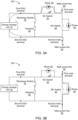
- Figs. 3A and 3B disclose the electrical protection circuit 100 in which the first NC switch 20 is configured to be opened to disconnect the ESU 10 from the main power line 80.
- the first NC switch 20 opens/breaks in the event of any fault condition. Opening of the first NC switch 20 disconnects the ESU 10 from the main power line/main connection 80. Thereby, providing electrical protection to the ESU 10. After disconnecting the ESU 10 from the system, the electrical protection circuit 100 may allow de-energization of energy stored in the ESU 10.
- Opening of the first NC switch 20 causes the first diode 30 and the second diode 50 to conduct depending on a direction of the charging current of the system. Opening of the first NC switch 20 causes the charging current to flow from the main power line 80 to the ESU 10 through the first diode 30, which is indicated by the curve in Fig. 3A . Opening of the first NC switch 20 causes the discharging current to flow to the main power line 80 through the second diode 50, which is indicated by the curve in Fig. 3B . Thereby disconnecting the ESU 10 from the main power line 80.
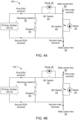
- Figs. 4A and 4B disclose the electrical protection circuit 100 in which the NO switch 40 is configured to be closed to bypass the ESU 10 from the main power line 80.
- the NO switch 40 closes. Closing of the NO switch 40 bypasses the current totally from the ESU 10, as depicted in Figs. 4A and 4B .
- the curve in Fig. 4A represents the charging current of the system and the curve in Fig. 4B represents the discharging current of the system.
- the electrical protection circuit 100 may be configured to maintain uninterrupted current flow for rest of system other than the ESU 10.
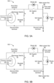
- Figs. 5A and 5B disclose the electrical protection circuit 100 in which the discharging switch 70 is configured to be closed to discharge the ESU 10.
- the discharging switch 70 closes/makes. Closing of the discharging switch 70 causes the ESU 10 to start discharging its energy through the resistor 60 connected in series with the discharging switch 70, as depicted in Figs. 5A and 5B .
- the curve in Fig. 5A represents the charging current of the system and the curve in Fig. 5B represents the discharging current of the system.
- the curve indicated around the ESU 10 in Figs. 5A and 5B represents a discharging curve of the disconnected ESU 10.
- electrical protection for the ESU 10 may be achieved by discharging the ESU 10. While providing electrical protection to the ESU 10, short-circuits may be avoided since a discharge path is provided after disconnection of the protected ESU 10.
- the discharging circuit comprising the discharging switch 70 and the resistor 60 may be arranged/designed in different configurations (including above) depending on the type of the ESU 10 and energy storage capability of the ESU 10.
- the discharging circuit may be designed by considering, for example, resistance, and over-discharge of the battery unit.
- the resistance for example, large resistance (several ohms and up) may be considered to guarantee requirements of long discharging time and to ensure that thermal runaway does not occur.
- the over-discharge of the battery unit may be considered when designing the discharge circuit that is for how to avoid over-discharge.
- ESU 10 comprises the supercapacitors.
- the discharging circuit may be designed without considering the resistance.
- the resistance could be either small or large (from tenths of milliohms and up) due to the discharging time may not be limited as for the battery unit.
- Figs. 6 , 7 , 8 , and 9 discloses example electrical protection circuit.
- a front view of the electrical protection circuit provided for the ESUs 10 connected in parallel is depicted in Fig. 6 .
- a right side view of the electrical protection circuit provided for the ESUs 10 connected in parallel is depicted in Fig. 7 .
- a left side view of the electrical protection circuit provided for the ESUs 10 connected in parallel is depicted in Fig. 8 .
- Atop view of the electrical protection circuit provided for the ESUs 10 connected in parallel is depicted in Fig. 9 .
- the electrical protection circuit is configured to provide electrical protection to the ESUs 10 connected in parallel.
- the ESUs 10 may comprise one or more of: a battery unit, and a supercapacitor.
- the electrical protection circuit comprises the first NC switch 20, the first diode 30, the NO switch 40, the second diode 50, and the discharging circuit.
- the discharging circuit comprises the resistor 60 and the discharging switch 70.
- the first NC switch 20, the NO switch 40, and the discharging switch 70 are connected to control/communication unit 102.
- the resistor 60 is connected to a heat sink 104.
- the first NC switch 20 is configured to be opened to disconnect the ESUs 10 from the main power line.
- the NO switch 40 is configured to be closed to bypass the ESUs 10 from the main power line.
- the discharging switch 70 is configured to be closed to cause the ESUs 10 to discharge its energy through the resistor 60.
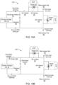
- Figs. 10A and 10B disclose the electrical protection circuit 100 in which the ESU 10 and the discharging circuit are disconnected from the main power line 80 for providing the electrical protection for the ESU 10.
- the electrical protection circuit 100 comprises the first and second main terminals connected to the main power line 80, the first and second ESU terminals connected to the ESU 10, the first NC switch 20, the first diode 30, the NO switch 40, the second diode 50, a second NC switch 90, and the discharging circuit.
- the discharging circuit comprises the resistor 60 and the discharging switch 70.
- the second NC switch 90 is connected in series with the first NC switch 20.
- the second NC switch 90 connected in series with the first NC switch 20 may be configured to disconnect the ESU 10 and the discharging circuit (the resistor 60 and the discharging switch 70) from the main power line 80. Thereby achieving electrical protection for the ESU 10.
- the electrical protection circuit 100 comprises the first and second main terminals connected to the main power line 80, the first and second ESU terminals connected to the ESU 10, the first NC switch 20, the first diode 30, the NO switch 40, the second diode 50, a third NC switch 95, and the discharging circuit.
- the third NC switch 95 is connected in series with the ESU 10.
- the third NC switch 95 connected in series with the ESU 10 may be configured to disconnect the ESU 10 from the discharging circuit (the resistor 60 and the discharging switch 70) and the main power line 80. Thereby achieving electrical protection for the ESU 10.
- the first NC switch, the second NC switch 90, the third NC switch 95, the NO switch 40, and the discharge switch 70 described herein may be of different types and may be connected in series or parallel configuration.
- the switch may include, but are not limited to, a mechanical switch, an electro-mechanical switch, a Silicon based switch, a WBG semiconductor switch, a pyrotechnical switch, an electron tube, or a combination thereof.
- Fig. 11 discloses the electrical protection circuit 100 in which closing of the NO switch 40 causes discharging of the ESU 10.
- the electrical protection circuit 100 comprises the first NC switch 20, the first diode 30, the NO switch 40, the second diode 50, and the resistor 60.
- the resistor 60 is connected in parallel to the first NC switch 20.
- the first NC switch 20 is configured to be opened thereby to disconnect the ESU 10 from the main power line 80 and the NO switch 40 is configured to be closed thereby to bypass the ESU 10 from the main power line 80 in order to achieve electrical protection for the ESU 10.
- the resistor 60 may be automatically connected to the first NC switch 20.
- closing of the NO switch 40 may cause the ESU 10 to discharge through the resistor 60 thereby achieving electrical protection for the ESU 10.
- an impedance of the resistor 60 has to be significantly higher than that of the first NC switch 20 and the first diode 30.
- Fig. 12 discloses the electrical protection circuit 100 in which a combination of a second NC switch and a third NC switch is configured to disconnect an ESU from a discharging circuit and a main power line.
- the electrical protection circuit 100 comprises the first and second main terminals connected to the main power line 80, the first and second ESU terminals connected to the ESU 10, the first NC switch 20, the first diode 30, the NO switch 40, the second diode 50, the second NC switch 90, the third NC switch 95, and the discharging circuit.
- the discharging circuit comprises the resistor 60 and the discharging switch 70.
- the second NC switch 90 is connected in series with the NC switch 20, thereby connecting the second NC switch 90 between the discharging circuit and the first NC switch 20.
- the third NC switch 95 is connected in series with the ESU 10, thereby connecting the third NC switch 95 between the ESU 10 and the discharging circuit.
- a combination of the second NC switch 90 and the third NC switch 95 is configured to disconnect the ESU 10 from the discharging circuit and the main power line 80. Thereby achieving electrical protection for the ESU 10.
- the first NC switch 20 is configured to be opened to disconnect the ESU 10 from the main power line 80 and the NO switch 40 is configured to be closed to bypass the ESU from the main power line. Operations of the first NC switch 20 and the NO switch 40 may precede the operation of the second NC switch 90 and the third NC switch 95.
- the second NC switch 90 may be configured to be opened to disconnect the ESU and the discharging circuit from the main power line 80
- the third NC switch 95 may be configured to be opened after opening of the second NC switch 90 and after discharging of the ESU through the resistor 60. Thereby, achieving electrical protection for the ESU 10.
- the third NC switch 95 may be configured to be opened after discharging of the ESU through the resistor 60 and the second NC switch is configured to be opened after opening of the third NC switch 95. Thereby achieving electrical protection for the ESU 10.
- Fig. 13 discloses an electrical circuit in which the first NC switch connected in parallel with the resistor and the second NC switch connected in series with an ESU are operated to disconnect an ESU from the main power line.
- the electrical protection circuit 100 comprises the first NC switch 20, the first diode 30, the NO switch 40, the second diode 50, the second NC switch 90, and the resistor 60.
- the resistor 60 is connected in parallel to the first NC switch 20.
- the second NC switch 90 is connected in between the ESU 10 and the parallel combination of the resistor 60 and the first NC switch 20.
- Opening of the first NC switch 20 and the second NC switch 90 may be controlled to disconnect the ESU 10 from the main power line 80. Thereby, achieving the electrical protection for the ESU 10.
- operations of the first NC switch 20 and the NO switch 40 may precede the operation of the second NC switch 90.
- the first NC switch 20 connected in parallel to the resistor is configured to be opened for causing the charging current to flow through the first diode or the second diode.
- the NO switch 40 is configured to be closed for discharging the ESU 10.
- the second NC switch 90 connected in between the ESU 10 and the parallel combination of the resistor 60 and the first NC switch 20 is configured to be opened for disconnecting the ESU 10 from the main power line 80, when the ESU 10 is discharged.
- Fig. 14 is a flowchart illustrating example method steps of a method 1400 for connecting the ESU to the main power line and providing electrical protection to the ESU.
- the ESU may comprise one or more of: a battery unit, and a supercapacitor.
- the method 1400 comprises opening the first NC switch to disconnect the ESU from the main power line.
- a parallel combination of the first NC switch and the first diode forms a closed path for both charging current and discharging current flowing between the main power line and the ESU during operation. Opening the first NC switch causes the charging current to flow from the ESU through the first diode. Opening of the first NC switch causes the discharging current to flow to the main power line through the second diode connected in parallel to NO switch, thereby disconnecting the ESU.
- the method 1400 comprises closing the NO switch to bypass current flowing through the ESU. Closing the NO switch causes the charging current and the discharging current to get diverted to at least resistance path provided by the parallel combination of the closed NO switch and the second diode, thereby bypassing the ESU.
- the electrical protection is provided to the ESU by opening the first NC switch to disconnect the ESU from the main power line and by closing the NO switch to bypass the ESU from the main power line.
- the method may further comprise maintaining an uninterrupted current flow for rest of the system other than the ESU during the bypassing.
- the method 1400 comprises closing the discharging switch to discharge the ESU through the resistor to provide the electrical protection to the ESU.
- the resistor is in series with the discharging switch.
- the discharging switch may be another NO switch.
- the method may comprise opening the second NC switch to disconnect the ESU and the resistor from the main power line to provide the electrical protection to the ESU.
- the second NC switch may be connected in series with the first NC switch.
- the method may comprise opening the third NC switch to disconnect the ESU from the resistor and the main power line to provide the electrical protection to the ESU.
- the third NC switch may be connected in series with the ESU.
- the method may comprise providing the electrical protection to the ESU by operating the second NC switch connected in series with the first NC switch and the third NC switch connected in series with the ESU in combination.
- the method may comprise opening the second NC switch to disconnect the ESU and the discharging circuit from the main power line, and opening the third NC switch after opening of the second NC switch and after discharging of the ESU through the resistor, thereby achieving electrical protection for the ESU.
- the method may comprise opening the third NC switch after discharging of the ESU through the resistor and opening of the second NC switch after opening of the third NC switch, thereby achieving electrical protection for the ESU.
- the method may comprise providing the electrical protection to the ESU by closing the NO switch that causes the ESU to discharge through the resistor.
- the resistor may be connected in parallel to the first NC switch.
- the method may comprise providing electrical protection to the ESU by operating a resistor connected in parallel to the first NC switch and a second NC switch connected in between the ESU and the parallel combination of the resistor and the first NC switch. More specifically, the method may comprise opening, the first NC switch connected in parallel to the resistor for causing the charging current to flow through the first diode or the second diode. The method may comprise closing the NO switch for discharging the ESU. The method may comprise opening, the second NC switch connected in between the ESU and the parallel combination of the resistor and the first NC switch, for disconnecting the ESU from the main power line, when the ESU is discharged.
- the NO switch, the first NC switch, and the discharging switch referred herein may be of same or different types and connectable in series or parallel configuration.
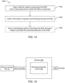
- Fig. 15 discloses a module 300 for providing electrical protection to the ESU 10.
- the module 300 comprises a first main terminal, a second main terminal, a first ESU terminal, a second ESU terminal, and the electrical protection circuit 100.
- the first and second main terminals are connected to the main power line.
- the second main terminal is configured for a lower electric potential than the first main terminal.
- the first ESU terminal is configured to be connected to a positive terminal of the ESU.
- the second ESU terminal configured to be connected to a negative terminal of the ESU.
- the electrical protection circuit 100 comprises the first NC switch, the first diode, the NO switch, and the second diode.
- the first NC switch is configured to form a closed path for both charging current and discharging current flowing between the main power line and the ESU 10 during operation.
- An anode of the first diode is connected to the first main terminal and a cathode of the first diode is connected to the second main terminal.
- the second diode is connected in parallel with the NO switch with a cathode connected to the first main terminal and an anode connected to the second main terminal.
- the module 300 is configured to provide the electrical protection to the ESU 10 by opening the first NC switch to disconnect the ESU 10 from the main power line and by closing the NO switch to bypass the ESU from the main power line.
- the electrical protection circuit 100 may also comprise the discharging circuit.
- the discharging circuit may comprise the resistor in series with the discharging switch.
- the module 300 is configured to provide the electrical protection to the ESU 10 by closing the discharging switch thereby to discharge the ESU 10 through the resistor 60 in order to achieve the electrical protection for the ESU 10.
Landscapes
- Engineering & Computer Science (AREA)
- Power Engineering (AREA)
- Charge And Discharge Circuits For Batteries Or The Like (AREA)
Abstract
Embodiments herein provide an electrical protection circuit (100) for connecting an Energy Storage Unit, ESU (10) to a main power line (80). The electrical protection circuit (100) comprises first and second main terminals configured to be connected to a main power line, first and second ESU terminals connected to the ESU (10). The first main terminal is connected to the first ESU terminal via a first normally closed, NC, switch (20). The first main terminal is connected to the second main terminal via a normally open, NO switch (40). The first NC switch (20) is configured to be opened thereby to disconnect the ESU (10) from the main power line (80), and the NO switch (40) is configured to be closed thereby to bypass the ESU (10) from the main power line (80) in order to achieve electrical protection for the ESU (10).
Description
- The present disclosure generally relates to energy storage units. More particularly, it relates to providing an electrical protection circuit for an energy storage unit, ESU.
- In general, an energy storage sector consists of several different branches of mediums/energy storage units, ESUs, to store energy. The ESUs include batteries, supercapacitors, or the like. In an event of a fault condition (for example, current overloading, rapid discharge, under voltage, or the like), the ESUs have to be protected.
- An electrical protection circuit can be used to protect an ESU. The protection circuit can implement a method of electrical protection for protecting the ESU. However, while protecting the energy storage unit electrically, the ESU behaves differently depending on an implemented method of electrical protection. Also, while protecting the ESU, consequences such as thermal runaway, arcing, venting, fire, or the like, can cause short-circuit.
- Further, in the prior art, for protecting different types of ESUs, different types of electrical protection circuits can be used, as the electrical protection circuit may not implement a single method of electrical protection for the different types of ESUs. For example, if a bypass protection method is implemented, then there may be possibility for protecting the supercapacitor depending on impedance of the bypass protection method. On the contrary, the battery may not be protected by implementing the bypass protection method due to thermal runaway.
- In addition, while protecting the ESU, if an electrical system uses opening/breaking devices, the electrical system may have an open circuit, which can cause very high over-voltage.
- Consequently, there is a need for a universal electrical protection circuit for protecting different types of ESUs by considering functionalities/features, which can be applicable for all the types of ESUs.
- It is therefore an object of the present disclosure to provide an electrical protection circuit for an energy storage unit, ESU, to mitigate, alleviate, or eliminate all or at least some of the above-discussed drawbacks of presently known solutions.
- This and other objects are achieved by means of an electrical protection circuit, as defined in the appended claims. The term exemplary is in the present context to be understood as serving as an instance, example or illustration.
- According to a first aspect of the present disclosure, an electrical protection circuit for connecting an energy storage unit, ESU, to a main power line is provided. The electrical protection circuit comprises a first main terminal configured to be connected to the main power line, a second main terminal configured to be connected to the main power line, wherein the second main terminal is configured for a lower electric potential than the first main terminal. The first ESU terminal configured to be connected to a positive terminal of the ESU and a second ESU terminal configured to be connected to a negative terminal of the ESU. The first main terminal is connected to the first ESU terminal via a first normally closed, NC, switch. The electrical protection circuit comprises a first diode with an anode connected to the first main terminal and a cathode connected to the first ESU terminal. A parallel combination of the first NC switch and the first diode forms a closed path for a charging current and a discharging current flowing between the main power line and the ESU during operation. The first main terminal is connected to the second main terminal via a normally open, NO, switch, and a second diode being connected in parallel with the NO switch with a cathode connected to the first main terminal, and an anode connected to the second main terminal. The first NC switch is configured to be opened thereby to disconnect the ESU from the main power line. The NO switch is configured to be closed thereby to bypass the ESU from the main power line in order to achieve electrical protection for the ESU.
- Thus, with the proposed topology, controllable and safe electrical protection circuit is provided, which combines disconnection and bypassing functionalities for providing electrical protection to the ESU.
- In some embodiments, the electrical protection circuit comprises a discharging circuit. The discharging circuit comprises a resistor in series with a discharging switch. The discharging circuit is connected between the first ESU terminal and the second ESU terminal. The discharging switch is a NO switch. The discharging switch is configured to be closed thereby to discharge the ESU through the resistor in order to achieve the electrical protection for the ESU.
- Advantageously, the proposed electrical protection circuit utilizes discharging functionality along with the disconnection and bypassing functionalities for providing electrical protection to the ESU.
- Further, the electrical protection circuit disclosed herein may act as universal protection circuit, as the combined functionalities (disconnection, bypassing, and discharging) of the electrical protection circuit may be applicable for all types of ESUs. For example, the electrical protection circuit may provide electrical protection for both battery unit and supercapacitor (exemplary types of the ESUs).
- Further, the usage of the electrical protection circuit disclosed herein for electrically protecting the ESU may increase reliability.
- Further, the electrical protection circuit disclosed herein may comprise small sized and less expensive components.
- In addition, as the electrical protection circuit disclosed herein may be used for different levels, availability of an Energy Storage, ES, system comprising the ESU may be increased.
- In some embodiments, the electrical protection circuit further comprises a second NC switch connected in series with the first NC switch. The second NC switch is configured to disconnect the ESU and the discharging circuit from the main power line thereby achieving electrical protection for the ESU.
- In some embodiments, the electrical protection circuit further comprises a third NC switch connected in series with the ESU. The third NC switch is configured to disconnect the ESU from the discharging circuit and the main power line thereby achieving electrical protection for the ESU.
- In some embodiments, the electrical protection circuit further comprises a second NC switch connected in series with the first NC switch and a third NC switch connected in series with the ESU. A combination of the second NC switch and the third NC switch is configured to disconnect the ESU and the discharging circuit from the main power line thereby achieving electrical protection for the ESU.
- In some embodiments, the second NC switch is configured to be opened to disconnect the ESU and the discharging circuit from the main power line, and the third NC switch is configured to be opened after opening of the second NC switch and after discharging of the ESU through the resistor, thereby achieving electrical protection for the ESU.
- In some embodiments, the third NC switch is configured to be opened after discharging of the ESU through the resistor and the second NC switch is configured to be opened after opening of the third NC switch, thereby achieving electrical protection for the ESU.
- In some embodiments, the electrical protection circuit further comprises a resistor connected in parallel to the first NC switch, wherein the closing of the NO switch causes the ESU to discharge through the resistor thereby achieving electrical protection for the ESU.
- In some embodiments, the electrical protection circuit further comprises a resistor connected in parallel to the first NC switch and a second NC switch connected in between the ESU and the parallel combination of the resistor and the first NC switch.
- In some embodiments, the first NC switch connected in parallel to the resistor is configured to be opened for causing the charging current to flow through the first diode or the second diode, the NO switch is configured to be closed for discharging the ESU, and the second NC switch connected in between the ESU and the parallel combination of the resistor and the first NC switch is configured to be opened for disconnecting the ESU from the main power line, when the ESU is discharged.
- In some embodiments, the first NC switch, the second NC switch, the third NC switch, the NO switch, and the discharging switch are of same or different types and connectable in series or parallel configuration.
- In some embodiments, the ESU is at least one of a battery unit or a supercapacitor.
- In some embodiments, the electrical protection circuit is configured to maintain uninterrupted current flow for rest of system other than the ESU during the bypassing.
- According to a second aspect of the present disclosure, a method for connecting an Energy Storage Unit, ESU, to a main power line is provided. The method comprises opening a first normally closed, NC, switch to disconnect the ESU from a main power line. A parallel combination of the first NC switch and a first diode forms a closed path for charging current and a discharging current flowing between the main power line and the ESU during operation. Opening the first NC switch causes the charging current to flow from the main power line to the ESU through a first diode. Opening the first NC switch causes the discharging current to flow to the main line through a second diode being connected in parallel with a normally open, NO, switch, thereby disconnecting the ESU. The method comprises closing the NO switch to bypass current flowing through the ESU. Closing the NO switch causes the charging current and the discharging current to get diverted to least resistance path provided by the parallel combination of the closed NO switch and the second diode thereby bypassing the ESU. The electrical protection is provided to the ESU by opening the first NC switch to disconnect the ESU from the main power line and by closing the NO switch to bypass the ESU from the main power line.
- In some embodiments, the method comprises closing a discharging switch to discharge the ESU through a resistor to provide the electrical protection to the ESU. The resistor is in series with the discharging switch, wherein the discharging switch is another NO switch.
- Thus, the ESU may be protected by combining disconnection, bypassing and discharging functionalities.
- According to a third aspect of the present disclosure, a module for connecting an Energy Storage Unit, ESU, to a main power line is provided. The module comprises a first main terminal configured to be connected to the main power line. The module comprises a second main terminal configured to be connected to the main power line, wherein the second main terminal is configured for a lower electric potential than the first main terminal. The module comprises a first ESU terminal configured to be connected to a positive terminal of the ESU. The module comprises a second ESU terminal configured to be connected to a negative terminal of the ESU. The module comprises an electrical protection circuit according to the first aspect of the present disclosure..
- Other advantages may be readily apparent to one having skill in the art. Certain embodiments may have some, or all of the recited advantages.
- The foregoing will be apparent from the following more particular description of the example embodiments, as illustrated in the accompanying drawings in which like reference characters refer to the same parts throughout the different views. The drawings are not necessarily to scale, emphasis instead being placed upon illustrating the example embodiments.
-
Fig. 1 discloses an electrical protection circuit for Energy Storage Unit, ESU according to some examples; -
Figs. 2A and 2B disclose an electrical protection circuit connecting an ESU to main power line according to some examples; -
Figs. 3A and 3B disclose an electrical protection circuit in which a first normally closed, NC, switch configured to be opened to disconnect an ESU from a main power line according to some examples; -
Figs. 4A and 4B disclose an electrical protection circuit in which a normally open, NO, switch is configured to be closed to bypass an ESU from a main power line according to some examples; -
Figs. 5A and 5B disclose an electrical protection circuit in which a discharging circuit is configured to be closed to discharge an ESU through a resistor according to some examples; -
Figs. 6 ,7 ,8 , and9 disclose an example electrical protection circuit; -
Fig. 10A and 10B disclose an electrical protection circuit in which an ESU and a discharging circuit are disconnected from a main power line for providing electrical protection for the ESU according to some examples; -
Fig. 11 discloses an electrical protection circuit in which closing of a NO switch causes discharging of an ESU according to some examples; -
Fig. 12 discloses an electrical protection circuit in which a combination of a second NC switch and a third NC switch is configured to disconnect an ESU from a discharging circuit and a main power line according to some examples; -
Fig. 13 discloses an electrical protection circuit in which a first NC switch connected in parallel with a resistor and a second NC switch connected in series with an ESU are operated to disconnect an ESU from a main power line according to some examples; -
Fig. 14 is a flowchart illustrating example method steps; and -
Fig. 15 discloses a module for providing electrical protection to an ESU according to some examples. - Aspects of the present disclosure will be described more fully hereinafter with reference to the accompanying drawings. The apparatus and methods disclosed herein can, however, be realized in many different forms and should not be construed as being limited to the aspects set forth herein. Like numbers in the drawings refer to like elements throughout.
- The terminology used herein is for the purpose of describing particular aspects of the disclosure only and is not intended to limit the invention. It should be emphasized that the term "comprises/comprising" when used in this specification is taken to specify the presence of stated features, integers, steps, or components, but does not preclude the presence or addition of one or more other features, integers, steps, components, or groups thereof. As used herein, the singular forms "a", "an" and "the" are intended to include the plural forms as well, unless the context clearly indicates otherwise.
-
Fig. 1 discloses anelectrical protection circuit 100 for an Energy Storage Unit,ESU 10. Theelectrical protection circuit 100 referred herein is configured for providing electrical protection to theESU 10. The electrical protection may be provided to theESU 10 in an event of one or more fault conditions such as, but not limited to, current overloading, rapid discharge, under voltage, or the like. In some examples, theESU 10 may comprise one or more of: a battery unit, a supercapacitor, or the like. - In the prior art, the electrical protection circuit may implement a method of electrical protection for protecting the
ESU 10. However, while protecting the energy storage unit electrically, theESU 10 behaves differently depending on an implemented method of electrical protection. Further, in the prior art, for protecting different types of ESUs, different types of electrical protection circuits can be used, as the electrical protection circuit may not implement a single method of electrical protection for the different types of ESUs. - Therefore, according to embodiments of the present disclosure, the controllable, safe, and universal
electrical protection circuit 100 is provided for providing electrical protection to theESU 10. - The
electrical protection circuit 100 connects theESU 10 to themain power line 80. Theelectrical protection circuit 100 comprises a first main terminal, a second main terminal, a first ESU terminal, a second ESU terminal, a first normally closed, NC, switch 20, afirst diode 30, a normally open, NO, switch 40, and asecond diode 50. - The first main terminal and the second main terminal are configured to be connected to the
main power line 80. The second main terminal is configured for a lower electric potential than the first main terminal. The first ESU terminal is configured to be connected to a positive terminal of theESU 10. The second ESU terminal is configured to be connected to a negative terminal of theESU 10. - The first main terminal is connected to the first ESU terminal via the
first NC switch 20. - An anode of the
first diode 30 is connected to the first main terminal and a cathode of thefirst diode 30 is connected to the first ESU terminal. A parallel combination of thefirst NC switch 20 and thefirst diode 30 forms a closed path for a charging current and a discharging current flowing between themain power line 80 and theESU 10 during operation. - The first main terminal is connected to the second main terminal via the
NO switch 40 and thesecond diode 50. Thesecond diode 50 is connected in parallel with theNO switch 40 with a cathode connected to the first main terminal and an anode connected to the second main terminal. - In some examples, the
first NC switch 20, and theNO switch 40 may be of same or different types and connectable in series or parallel configuration. Examples of the switch may include, but are not limited to, a mechanical switch, an electro-mechanical switch, a Silicon based switch, a Wide bandgap, WBG, based semiconductor switch, a pyrotechnical switch, an electron tube, or a combination thereof. As would be understood, any similar type of above described switch may be considered herein. - The
first NC switch 20 is configured to be opened thereby to disconnect theESU 10 from themain power line 80. TheNO switch 40 is configured to be closed thereby to bypass theESU 10 from themain power line 80. Thereby, achieving electrical protection for theESU 10. - Opening of the
first NC switch 20 causes the charging current to flow from themain power line 80 to theESU 10 through thefirst diode 30 and causes the discharging current to flow to themain power line 80 through thesecond diode 50. Thereby disconnecting theESU 10 from themain power line 80. - Closing of the NO switch causes the charging current and the discharging current to be diverted to at least resistance path provided by the parallel combination of the
closed NO switch 40 and thesecond diode 50. Thereby, bypassing theESU 10. During the bypassing of theESU 10 from themain power line 80, theelectrical protection circuit 100 may be configured to maintain uninterrupted current flow for rest of system other than theESU 10. The system referred herein may be an electrical system/Energy Storage, ES, system comprising theESU 10. - Thus, the
electrical protection circuit 100 disclosed herein utilizes disconnection and bypassing functionality/protection methods for protecting theESU 10 electrically. - The
electrical protection circuit 100 may further comprise a discharging circuit. The discharging circuit may comprise aresistor 60 in series with a dischargingswitch 70. The discharging circuit may be connected between the first ESU terminal and the second ESU terminal. In some examples, the dischargingswitch 70 may be another NO switch. In some examples, the dischargingswitch 70 may be of different types and may be connected in series or parallel configuration. Examples of the switch may include, but are not limited to, a mechanical switch, an electro-mechanical switch, a Silicon based switch, a WBG semiconductor switch, a pyrotechnical switch, an electron tube, or a combination thereof. - The discharging
switch 70 may be configured to be closed thereby to discharge theESU 10 through theresistor 60 in order to achieve the electrical protection for theESU 10. In some examples, the discharging of theESU 10 may be carried out for a long period of time (for example, hours/days). - Thus, discharging functionality may also be combined with the disconnection and bypassing functionality for providing the electrical protection to the
ESU 10. With the disconnection, bypassing, and discharging functionalities combined, theelectrical protection circuit 100 may be designed for the both the battery unit and the supercapacitor (i.e., for any type of ESUs 10). However, it should be noted that an arrangement of the components of theelectrical protection unit 100 may be differed for each type of theESU 10. - Optionally, the
electrical protection circuit 100 may comprise an over voltage protection for switches such as thefirst NC switch 20, and theNO switch 40. -
Figs. 2A and 2B disclose theelectrical protection circuit 100 configured to connect theESU 10 to themain power line 80 and protect theESU 10 by combining disconnection, bypassing, and discharging functionalities. Theelectrical protection circuit 100 comprises the first and second main terminals connected to themain power line 80, the first and second ESU terminals connected to theESU 10, thefirst NC switch 20, thefirst diode 30, theNO switch 40, thesecond diode 50, and the discharging circuit. The discharging circuit comprises theresistor 60 and the dischargingswitch 70. - The parallel combination of the
first NC switch 20 and thefirst diode 30 is configured to provide a closed path for the charging current and the discharging current flowing between the main power line and the ESU during operation. The curve indicated inFig. 2A represents a flow of the charging/operational current in thecircuit 100 during a normal operation of the circuit. The curve indicated inFig. 2B represents the discharging current in the normal operation state of theESU 10. - In the event of any fault conditions, the
first NC switch 20 opens and disconnects theESU 10 from themain power line 80. Upon disconnection of theESU 10 from themain power line 80, theNO switch 40 closes and bypasses theESU 10 from themain power line 80. Due to the bypass, an operation of the electrical/ES system comprising theESU 10 may be continued. The failedESU 10 may be discharged while being disconnected from themain power line 80/ES system. The dischargingswitch 70 closes and causes theESU 10 to discharge its energy through theresistor 60. - Thus, the
electrical protection circuit 100 provides electrical protection to theESU 10 by combining the disconnection, bypassing and/or discharging functionalities. Such anelectrical protection circuit 100 may increase reliability and reduce time need for maintenance. Also, theelectrical protection circuit 100 disclosed herein may comprise small sized and less expensive components, which ultimately reduces total cost of theelectrical protection circuit 100. In addition, as theelectrical protection circuit 100 may be used for different levels (for example, module level), availability of the ES system may be increased. - In some examples, using power electronic switches or the like, balancing functions may be implemented on energy string level, for example, NO/NC switches may be ON/OFF for certain period of time to balance energy modules of the
ESU 10. -
Figs. 3A and 3B disclose theelectrical protection circuit 100 in which thefirst NC switch 20 is configured to be opened to disconnect theESU 10 from themain power line 80. - For providing the electrical protection to the
ESU 10, thefirst NC switch 20 opens/breaks in the event of any fault condition. Opening of thefirst NC switch 20 disconnects theESU 10 from the main power line/main connection 80. Thereby, providing electrical protection to theESU 10. After disconnecting theESU 10 from the system, theelectrical protection circuit 100 may allow de-energization of energy stored in theESU 10. - Opening of the
first NC switch 20 causes thefirst diode 30 and thesecond diode 50 to conduct depending on a direction of the charging current of the system. Opening of thefirst NC switch 20 causes the charging current to flow from themain power line 80 to theESU 10 through thefirst diode 30, which is indicated by the curve inFig. 3A . Opening of thefirst NC switch 20 causes the discharging current to flow to themain power line 80 through thesecond diode 50, which is indicated by the curve inFig. 3B . Thereby disconnecting theESU 10 from themain power line 80. -
Figs. 4A and 4B disclose theelectrical protection circuit 100 in which theNO switch 40 is configured to be closed to bypass theESU 10 from themain power line 80. - When the
ESU 10 is disconnected from themain power line 80, theNO switch 40 closes. Closing of theNO switch 40 bypasses the current totally from theESU 10, as depicted inFigs. 4A and 4B . The curve inFig. 4A represents the charging current of the system and the curve inFig. 4B represents the discharging current of the system. During the bypassing of theESU 10 from themain power line 80, theelectrical protection circuit 100 may be configured to maintain uninterrupted current flow for rest of system other than theESU 10. -
Figs. 5A and 5B disclose theelectrical protection circuit 100 in which the dischargingswitch 70 is configured to be closed to discharge theESU 10. - When the
ESU 10 is disconnected and bypassed from themain power line 80, the dischargingswitch 70 closes/makes. Closing of the dischargingswitch 70 causes theESU 10 to start discharging its energy through theresistor 60 connected in series with the dischargingswitch 70, as depicted inFigs. 5A and 5B . The curve inFig. 5A represents the charging current of the system and the curve inFig. 5B represents the discharging current of the system. The curve indicated around theESU 10 inFigs. 5A and 5B represents a discharging curve of the disconnectedESU 10. - Thus, electrical protection for the
ESU 10 may be achieved by discharging theESU 10. While providing electrical protection to theESU 10, short-circuits may be avoided since a discharge path is provided after disconnection of the protectedESU 10. - As would be understood, the discharging circuit comprising the discharging
switch 70 and theresistor 60 may be arranged/designed in different configurations (including above) depending on the type of theESU 10 and energy storage capability of theESU 10. - In an example, consider that the
ESU 10 comprises the battery unit, then the discharging circuit may be designed by considering, for example, resistance, and over-discharge of the battery unit. The resistance, for example, large resistance (several ohms and up) may be considered to guarantee requirements of long discharging time and to ensure that thermal runaway does not occur. The over-discharge of the battery unit may be considered when designing the discharge circuit that is for how to avoid over-discharge. - In another example, consider that
ESU 10 comprises the supercapacitors. In such a case, the discharging circuit may be designed without considering the resistance. The resistance could be either small or large (from tenths of milliohms and up) due to the discharging time may not be limited as for the battery unit. -
Figs. 6 ,7 ,8 , and9 discloses example electrical protection circuit. A front view of the electrical protection circuit provided for theESUs 10 connected in parallel is depicted inFig. 6 . A right side view of the electrical protection circuit provided for theESUs 10 connected in parallel is depicted inFig. 7 . A left side view of the electrical protection circuit provided for theESUs 10 connected in parallel is depicted inFig. 8 . Atop view of the electrical protection circuit provided for theESUs 10 connected in parallel is depicted inFig. 9 . - The electrical protection circuit is configured to provide electrical protection to the
ESUs 10 connected in parallel. TheESUs 10 may comprise one or more of: a battery unit, and a supercapacitor. - The electrical protection circuit comprises the
first NC switch 20, thefirst diode 30, theNO switch 40, thesecond diode 50, and the discharging circuit. The discharging circuit comprises theresistor 60 and the dischargingswitch 70. - The
first NC switch 20, theNO switch 40, and the dischargingswitch 70 are connected to control/communication unit 102. Theresistor 60 is connected to aheat sink 104. - For providing the electrical protection to the
ESUs 10, thefirst NC switch 20 is configured to be opened to disconnect theESUs 10 from the main power line. TheNO switch 40 is configured to be closed to bypass theESUs 10 from the main power line. The dischargingswitch 70 is configured to be closed to cause theESUs 10 to discharge its energy through theresistor 60. Thus, the disconnection, bypassing and discharging functionalities are combined in order to achieve the electrical protection for theESUs 10. -
Figs. 10A and 10B disclose theelectrical protection circuit 100 in which theESU 10 and the discharging circuit are disconnected from themain power line 80 for providing the electrical protection for theESU 10. - As depicted in
Fig. 10A , theelectrical protection circuit 100 comprises the first and second main terminals connected to themain power line 80, the first and second ESU terminals connected to theESU 10, thefirst NC switch 20, thefirst diode 30, theNO switch 40, thesecond diode 50, asecond NC switch 90, and the discharging circuit. The discharging circuit comprises theresistor 60 and the dischargingswitch 70. Thesecond NC switch 90 is connected in series with thefirst NC switch 20. Thesecond NC switch 90 connected in series with thefirst NC switch 20 may be configured to disconnect theESU 10 and the discharging circuit (theresistor 60 and the discharging switch 70) from themain power line 80. Thereby achieving electrical protection for theESU 10. - As depicted in
Fig. 10B , theelectrical protection circuit 100 comprises the first and second main terminals connected to themain power line 80, the first and second ESU terminals connected to theESU 10, thefirst NC switch 20, thefirst diode 30, theNO switch 40, thesecond diode 50, athird NC switch 95, and the discharging circuit. Thethird NC switch 95 is connected in series with theESU 10. Thethird NC switch 95 connected in series with theESU 10 may be configured to disconnect theESU 10 from the discharging circuit (theresistor 60 and the discharging switch 70) and themain power line 80. Thereby achieving electrical protection for theESU 10. - In some embodiments, the first NC switch, the
second NC switch 90, thethird NC switch 95, theNO switch 40, and thedischarge switch 70 described herein may be of different types and may be connected in series or parallel configuration. Examples of the switch may include, but are not limited to, a mechanical switch, an electro-mechanical switch, a Silicon based switch, a WBG semiconductor switch, a pyrotechnical switch, an electron tube, or a combination thereof. -
Fig. 11 discloses theelectrical protection circuit 100 in which closing of theNO switch 40 causes discharging of theESU 10. As depicted inFig. 11 , theelectrical protection circuit 100 comprises thefirst NC switch 20, thefirst diode 30, theNO switch 40, thesecond diode 50, and theresistor 60. Theresistor 60 is connected in parallel to thefirst NC switch 20. - The
first NC switch 20 is configured to be opened thereby to disconnect theESU 10 from themain power line 80 and theNO switch 40 is configured to be closed thereby to bypass theESU 10 from themain power line 80 in order to achieve electrical protection for theESU 10. - After bypassing the
ESU 10 from themain power line 80, theresistor 60 may be automatically connected to thefirst NC switch 20. When the resistor is connected to thefirst NC switch 20, closing of theNO switch 40 may cause theESU 10 to discharge through theresistor 60 thereby achieving electrical protection for theESU 10. As would be understood, for discharging theESU 10 by closing of theNO switch 40, an impedance of theresistor 60 has to be significantly higher than that of thefirst NC switch 20 and thefirst diode 30. -
Fig. 12 discloses theelectrical protection circuit 100 in which a combination of a second NC switch and a third NC switch is configured to disconnect an ESU from a discharging circuit and a main power line. As depicted inFig. 12 , theelectrical protection circuit 100 comprises the first and second main terminals connected to themain power line 80, the first and second ESU terminals connected to theESU 10, thefirst NC switch 20, thefirst diode 30, theNO switch 40, thesecond diode 50, thesecond NC switch 90, thethird NC switch 95, and the discharging circuit. The discharging circuit comprises theresistor 60 and the dischargingswitch 70. - The
second NC switch 90 is connected in series with theNC switch 20, thereby connecting thesecond NC switch 90 between the discharging circuit and thefirst NC switch 20. - The
third NC switch 95 is connected in series with theESU 10, thereby connecting thethird NC switch 95 between theESU 10 and the discharging circuit. - A combination of the
second NC switch 90 and thethird NC switch 95 is configured to disconnect theESU 10 from the discharging circuit and themain power line 80. Thereby achieving electrical protection for theESU 10. - More specifically, the
first NC switch 20 is configured to be opened to disconnect theESU 10 from themain power line 80 and theNO switch 40 is configured to be closed to bypass the ESU from the main power line. Operations of thefirst NC switch 20 and theNO switch 40 may precede the operation of thesecond NC switch 90 and thethird NC switch 95. - In some embodiments, the
second NC switch 90 may be configured to be opened to disconnect the ESU and the discharging circuit from themain power line 80, and thethird NC switch 95 may be configured to be opened after opening of thesecond NC switch 90 and after discharging of the ESU through theresistor 60. Thereby, achieving electrical protection for theESU 10. - In some embodiments, the
third NC switch 95 may be configured to be opened after discharging of the ESU through theresistor 60 and the second NC switch is configured to be opened after opening of thethird NC switch 95. Thereby achieving electrical protection for theESU 10. -
Fig. 13 discloses an electrical circuit in which the first NC switch connected in parallel with the resistor and the second NC switch connected in series with an ESU are operated to disconnect an ESU from the main power line. As depicted inFig. 13 , theelectrical protection circuit 100 comprises thefirst NC switch 20, thefirst diode 30, theNO switch 40, thesecond diode 50, thesecond NC switch 90, and theresistor 60. - The
resistor 60 is connected in parallel to thefirst NC switch 20. Thesecond NC switch 90 is connected in between theESU 10 and the parallel combination of theresistor 60 and thefirst NC switch 20. - Opening of the
first NC switch 20 and thesecond NC switch 90 may be controlled to disconnect theESU 10 from themain power line 80. Thereby, achieving the electrical protection for theESU 10. - More specifically, operations of the
first NC switch 20 and theNO switch 40 may precede the operation of thesecond NC switch 90. Thefirst NC switch 20 connected in parallel to the resistor is configured to be opened for causing the charging current to flow through the first diode or the second diode. TheNO switch 40 is configured to be closed for discharging theESU 10. Thesecond NC switch 90 connected in between theESU 10 and the parallel combination of theresistor 60 and thefirst NC switch 20 is configured to be opened for disconnecting theESU 10 from themain power line 80, when theESU 10 is discharged. -
Fig. 14 is a flowchart illustrating example method steps of amethod 1400 for connecting the ESU to the main power line and providing electrical protection to the ESU. In some examples, the ESU may comprise one or more of: a battery unit, and a supercapacitor. - At
step 1402, themethod 1400 comprises opening the first NC switch to disconnect the ESU from the main power line. A parallel combination of the first NC switch and the first diode forms a closed path for both charging current and discharging current flowing between the main power line and the ESU during operation. Opening the first NC switch causes the charging current to flow from the ESU through the first diode. Opening of the first NC switch causes the discharging current to flow to the main power line through the second diode connected in parallel to NO switch, thereby disconnecting the ESU. - At
step 1404, themethod 1400 comprises closing the NO switch to bypass current flowing through the ESU. Closing the NO switch causes the charging current and the discharging current to get diverted to at least resistance path provided by the parallel combination of the closed NO switch and the second diode, thereby bypassing the ESU. - Thus, the electrical protection is provided to the ESU by opening the first NC switch to disconnect the ESU from the main power line and by closing the NO switch to bypass the ESU from the main power line.
- In some embodiments, the method may further comprise maintaining an uninterrupted current flow for rest of the system other than the ESU during the bypassing.
- Optionally, at
step 1406, themethod 1400 comprises closing the discharging switch to discharge the ESU through the resistor to provide the electrical protection to the ESU. The resistor is in series with the discharging switch. The discharging switch may be another NO switch. - In some embodiments, the method may comprise opening the second NC switch to disconnect the ESU and the resistor from the main power line to provide the electrical protection to the ESU. The second NC switch may be connected in series with the first NC switch.
- In some embodiments, the method may comprise opening the third NC switch to disconnect the ESU from the resistor and the main power line to provide the electrical protection to the ESU. The third NC switch may be connected in series with the ESU.
- In some embodiments, the method may comprise providing the electrical protection to the ESU by operating the second NC switch connected in series with the first NC switch and the third NC switch connected in series with the ESU in combination. In some examples, the method may comprise opening the second NC switch to disconnect the ESU and the discharging circuit from the main power line, and opening the third NC switch after opening of the second NC switch and after discharging of the ESU through the resistor, thereby achieving electrical protection for the ESU. In some examples, the method may comprise opening the third NC switch after discharging of the ESU through the resistor and opening of the second NC switch after opening of the third NC switch, thereby achieving electrical protection for the ESU.
- In some embodiments, the method may comprise providing the electrical protection to the ESU by closing the NO switch that causes the ESU to discharge through the resistor. The resistor may be connected in parallel to the first NC switch.
- In some embodiments, the method may comprise providing electrical protection to the ESU by operating a resistor connected in parallel to the first NC switch and a second NC switch connected in between the ESU and the parallel combination of the resistor and the first NC switch. More specifically, the method may comprise opening, the first NC switch connected in parallel to the resistor for causing the charging current to flow through the first diode or the second diode. The method may comprise closing the NO switch for discharging the ESU. The method may comprise opening, the second NC switch connected in between the ESU and the parallel combination of the resistor and the first NC switch, for disconnecting the ESU from the main power line, when the ESU is discharged.
- In some examples, the NO switch, the first NC switch, and the discharging switch referred herein may be of same or different types and connectable in series or parallel configuration.
-
Fig. 15 discloses amodule 300 for providing electrical protection to theESU 10. As depicted inFig. 15 , themodule 300 comprises a first main terminal, a second main terminal, a first ESU terminal, a second ESU terminal, and theelectrical protection circuit 100. - The first and second main terminals are connected to the main power line. The second main terminal is configured for a lower electric potential than the first main terminal. The first ESU terminal is configured to be connected to a positive terminal of the ESU. The second ESU terminal configured to be connected to a negative terminal of the ESU.
- The
electrical protection circuit 100 comprises the first NC switch, the first diode, the NO switch, and the second diode. The first NC switch is configured to form a closed path for both charging current and discharging current flowing between the main power line and theESU 10 during operation. An anode of the first diode is connected to the first main terminal and a cathode of the first diode is connected to the second main terminal. The second diode is connected in parallel with the NO switch with a cathode connected to the first main terminal and an anode connected to the second main terminal. - The
module 300 is configured to provide the electrical protection to theESU 10 by opening the first NC switch to disconnect theESU 10 from the main power line and by closing the NO switch to bypass the ESU from the main power line. - The
electrical protection circuit 100 may also comprise the discharging circuit. The discharging circuit may comprise the resistor in series with the discharging switch. Themodule 300 is configured to provide the electrical protection to theESU 10 by closing the discharging switch thereby to discharge theESU 10 through theresistor 60 in order to achieve the electrical protection for theESU 10. - As the
electrical protection circuit 100 is described in detail in conjunction withFigs. 1-13 , repetition of description is omitted herein. - The foregoing description of the specific embodiments will so fully reveal the general nature of the embodiments herein that others can, by applying current knowledge, readily modify and/or adapt for various applications such specific embodiments without departing from the generic concept, and, therefore, such adaptations and modifications should and are intended to be comprehended within the meaning and range of equivalents of the disclosed embodiments. It is to be understood that the phraseology or terminology employed herein is for the purpose of description and not of limitation. Therefore, while the embodiments herein have been described in terms of preferred embodiments, those skilled in the art will recognize that the embodiments herein can be practiced with modification within the scope of the disclosure.
Claims (25)
- An electrical protection circuit (100) for connecting an Energy Storage Unit, ESU (10), to a main power line (80), wherein the electrical protection circuit (100) comprising:a first main terminal configured to be connected to the main power line (80);a second main terminal configured to be connected to the main power line (80), wherein the second main terminal is configured for a lower electric potential than the first main terminal;a first ESU terminal configured to be connected to a positive terminal of the ESU (10);a second ESU terminal configured to be connected to a negative terminal of the ESU (10);wherein the first main terminal is connected to the first ESU terminal via a first normally closed, NC, switch (20); anda first diode (30) with an anode connected to the first main terminal, and a cathode connected to the first ESU terminal, wherein a parallel combination of the first NC switch (20) and the first diode (30) forms a closed path for a charging current and a discharging current flowing between the main power line (80) and the ESU (10) during operation;wherein the first main terminal is connected to the second main terminal via a normally open, NO, switch (40) and a second diode (50) being connected in parallel with the NO switch (40) with a cathode connected to the first main terminal, and an anode connected to the second main terminal;wherein the first NC switch (20) is configured to be opened thereby to disconnect the ESU (10) from the main power line (80), and the NO switch (40) is configured to be closed thereby to bypass the ESU (10) from the main power line (80) in order to achieve electrical protection for the ESU (10).
- The electrical protection circuit (100) according to claim 1, further comprising:
a discharging circuit comprising a resistor (60) in series with a discharging switch (70), wherein the discharging circuit is connected between the first ESU terminal and the second ESU terminal, wherein the discharging switch (70) is a NO switch;
wherein the discharging switch (70) is configured to be closed thereby to discharge the ESU (10) through the resistor (60) in order to achieve the electrical protection for the ESU (10). - The electrical protection circuit (100) according to any of the preceding claims, further comprising:
a second NC switch (90) connected in series with the first NC switch (20), wherein the second NC switch (90) is configured to disconnect the ESU (10) and the discharging circuit from the main power line (80) thereby achieving electrical protection for the ESU (10). - The electrical protection circuit (100) according to any of claims 1-2, further comprising:
a third NC switch (95) connected in series with the ESU (10), wherein the third NC switch (95) is configured to disconnect the ESU (10) from the discharging circuit and the main power line (80) thereby achieving electrical protection for the ESU (10). - The electrical protection circuit (100) according to any of claims 1 or 2, further comprising:a second NC switch (90) connected in series with the first NC switch (20); anda third NC switch (95) connected in series with the ESU (10), wherein a combination of the second NC switch (90) and the third NC switch (95) is configured to disconnect the ESU (10) and the discharging circuit from the main power line (80) thereby achieving electrical protection for the ESU (10).
- The electrical protection circuit (100) according to claim 5, whereinthe second NC switch (90) is configured to be opened to disconnect the ESU (10) and the discharging circuit from the main power line (80); andthe third NC switch (95) is configured to be opened after opening of the second NC switch (90) and discharging of the ESU (10) through the resistor (60), thereby achieving electrical protection for the ESU (10).
- The electrical protection circuit (100) according to claim 5, whereinthe third NC switch (95) is configured to be opened after discharging of the ESU (10) through the resistor (60); andthe second NC switch (90) is configured to be opened after opening of the third NC switch (95), thereby achieving electrical protection for the ESU (10).
- The electrical protection circuit (100) according to claim 1, further comprising:
a resistor (60) connected in parallel to the first NC switch (20), wherein the closing of the NO switch (40) causes the ESU (10) to discharge through the resistor (60) thereby achieving electrical protection for the ESU (10). - The electrical protection circuit (100) according to claim 1, further comprising:a resistor (60) connected in parallel to the first NC switch (20); anda second NC switch (90) connected in between the ESU (10) and the parallel combination of the resistor (60) and the first NC switch (20).
- The electrical protection circuit (100) according to claims 1 and 9, whereinthe first NC switch (20) connected in parallel to the resistor (60) is configured to be opened for causing the charging current to flow through the first diode (30) or the second diode (50);the NO switch (40) is configured to be closed for discharging the ESU (10); andthe second NC switch (90) connected in between the ESU (10) and the parallel combination of the resistor (60) and the first NC switch (20) is configured to be opened for disconnecting the ESU (10) from the main power line (80), when the ESU (10) is discharged.
- The electrical protection circuit (100) according to any of the preceding claims, wherein the first NC switch (20), the second NC switch (90), the third NC switch (95), the NO switch (40), and the discharging switch (70) are of same or different types and connectable in series or parallel configuration.
- The electrical protection circuit (100) according to any of the preceding claims,wherein the ESU (10) is at least one of a battery unit or a supercapacitor; andwherein the electrical protection circuit (100) is configured to maintain uninterrupted current flow for rest of system other than the ESU (10) during the bypassing.
- A method (1400) for connecting an Energy Storage Unit, ESU (10), to a main power line (80), the method (1400) comprising:opening (1402) a first normally closed, NC, switch (20) to disconnect the ESU (10) from the main power line (80),wherein a parallel combination of the first NC switch (20) and a first diode (30) forms a closed path for a charging current and a discharging current flowing between the main power line (80) and the ESU (10) during operation,wherein opening the first NC switch (20) causes the charging current to flow from the main power line (80) to the ESU (10) through the first diode (30) andwherein opening the first NC switch (20) causes the discharging current to flow to the main power line (80) through a second diode (50) being connected in parallel with a normally open, NO, switch (40), thereby disconnecting the ESU (10); andclosing (1404) the NO switch (40) to bypass current flowing through the ESU (10), wherein closing the NO switch (40) causes the charging current and the discharging current to get diverted to least resistance path provided by the parallel combination of the closed NO switch (40) and the second diode (50) thereby bypassing the ESU (10);wherein the electrical protection is provided to the ESU (10) by opening the first NC switch (20) to disconnect the ESU (10) from the main power line (80) and by closing the NO switch (40) to bypass the ESU (10) from the main power line (80).
- The method (1400) according to claim 13, further comprising:closing (1406) a discharging switch (70) to discharge the ESU (10) through a resistor (60) to provide the electrical protection to the ESU (10),wherein the resistor (60) is in series with the discharging switch (70), wherein the discharging switch (70) is another NO switch.
- The method (1400) according to any of claims 13-14, further comprising:
opening a second NC switch (90) to disconnect the ESU (10) and the resistor (60) from the main power line (80) to provide the electrical protection to the ESU (10), wherein the second NC switch (90) is connected in series with the first NC switch (20). - The method (1400) according to any of claims 13-14, further comprising:
opening a third NC switch (95) to disconnect the ESU (10) from the resistor (60) and the main power line (80) to provide the electrical protection to the ESU (10), wherein the third NC switch (95) is connected in series with the ESU (10). - The method (1400) according to any of claims 13 or 14, further comprising:
providing the electrical protection to the ESU (10) by operating a second NC switch (90) connected in series with the first NC switch (20) and a third NC switch (95) connected in series with the ESU (10) in combination. - The method (1400) according to claim 17, further comprising:
providing the electrical protection to the ESU (10) by opening the second NC switch (90) to disconnect the ESU (10) and the discharging circuit from the main power line (80) and opening the third switch (95) after opening of the second NC switch (90) and discharging of the ESU (10) through the resistor (60). - The method (1400) according to claim 17, further comprising:
providing the electrical protection to the ESU (10) by opening the third NC switch (95) after discharging of the ESU (10) through the resistor (60) and opening the second NC switch (90) after opening of the third NC switch (95). - The method (1400) according to claim 13, further comprising:
providing the electrical protection to the ESU (10) by closing the NO switch (40) that causes the ESU (10) to discharge through the resistor (60), wherein the resistor (60) is connected in parallel to the first NC switch (20). - The method (1400) according to claim 13, further comprising:
providing the electrical protection to the ESU (10) by operating a resistor (60) connected in parallel to the first NC switch (20) and a second NC switch (90) connected in between the ESU (10) and the parallel combination of the resistor (60) and the first NC switch (20). - The method (1400) according to claims 13 and 21, further comprising:opening the first NC switch (20) connected in parallel to the resistor (60) for causing the charging current to flow through the first diode (30) or the second diode (50);closing the NO switch (40) for discharging the ESU (10); andopening the second NC switch (90) connected in between the ESU (10) and the parallel combination of the resistor (60) and the first NC switch (20) for disconnecting the ESU (10) from the main power line (80), when the ESU (10) is discharged.
- The method (1400) according to any of claims 13-21, wherein the first NC switch (20), the second NC switch (90), the third NC switch (95), the NO switch (40), and the discharging switch (70) are of same or different types and connectable in series or parallel.
- The method (1400) according to any of claims 13-22, further comprising:
maintaining an uninterrupted current flow for rest of system other than the ESU (10) during the bypassing, wherein the ESU (10) is at least one of a battery unit or a supercapacitor. - A module (300) for connecting an Energy Storage Unit, ESU, (10) to a main power line, the module (300) comprising:a first main terminal configured to be connected to the main power line (80);a second main terminal configured to be connected to the main power line (80), wherein the second main terminal is configured for a lower electric potential than the first main terminal;a first ESU terminal configured to be connected to a positive terminal of the ESU (10);a second ESU terminal configured to be connected to a negative terminal of the ESU (10); andan electrical protection circuit (100) according to any of claims 1-12.
Priority Applications (3)
| Application Number | Priority Date | Filing Date | Title |
|---|---|---|---|
| US19/167,543 US20260128581A1 (en) | 2023-03-24 | 2024-03-22 | Electrical protection circuit for energy storage unit |
| CN202480017725.3A CN120858501A (en) | 2023-03-24 | 2024-03-22 | Electrical protection circuit for energy storage units |
| PCT/EP2024/057844 WO2024200298A1 (en) | 2023-03-24 | 2024-03-22 | Electrical protection circuit for energy storage unit |
Applications Claiming Priority (1)
| Application Number | Priority Date | Filing Date | Title |
|---|---|---|---|
| GR20230100247 | 2023-03-24 |
Publications (1)
| Publication Number | Publication Date |
|---|---|
| EP4435989A1 true EP4435989A1 (en) | 2024-09-25 |
Family
ID=92541365
Family Applications (1)
| Application Number | Title | Priority Date | Filing Date |
|---|---|---|---|
| EP23169650.1A Pending EP4435989A1 (en) | 2023-03-24 | 2023-04-25 | Electrical protection circuit for energy storage unit |
Country Status (1)
| Country | Link |
|---|---|
| EP (1) | EP4435989A1 (en) |
Citations (3)
| Publication number | Priority date | Publication date | Assignee | Title |
|---|---|---|---|---|
| CN104253469A (en) * | 2014-09-24 | 2014-12-31 | 于志章 | Secondary battery pack charging and discharging management system |
| US20190245359A1 (en) * | 2016-10-28 | 2019-08-08 | Sanyo Electric Co., Ltd. | Power supply device |
| US20200373768A1 (en) * | 2019-05-24 | 2020-11-26 | Witricity Corporation | Protection circuits for wireless power receivers |
-
2023
- 2023-04-25 EP EP23169650.1A patent/EP4435989A1/en active Pending
Patent Citations (3)
| Publication number | Priority date | Publication date | Assignee | Title |
|---|---|---|---|---|
| CN104253469A (en) * | 2014-09-24 | 2014-12-31 | 于志章 | Secondary battery pack charging and discharging management system |
| US20190245359A1 (en) * | 2016-10-28 | 2019-08-08 | Sanyo Electric Co., Ltd. | Power supply device |
| US20200373768A1 (en) * | 2019-05-24 | 2020-11-26 | Witricity Corporation | Protection circuits for wireless power receivers |
Similar Documents
| Publication | Publication Date | Title |
|---|---|---|
| US11984719B2 (en) | Quick battery disconnect system for high current circuits | |
| US8842404B2 (en) | Short circuit protection device and switchgear assembly having such protection devices | |
| RU2500062C2 (en) | High-speed switching device for high-power accumulator battery in isolated dc circuit | |
| CN114336817A (en) | Intelligent battery disconnection and protection framework of onboard high-power modular multi-string battery pack | |
| US10026948B2 (en) | Safety element for battery cell | |
| US9478996B2 (en) | Battery cell unit comprising a battery cell and a monitoring and actuation unit for monitoring the battery cell and method for monitoring a battery cell | |
| CN113039718B (en) | Photovoltaic string junction box with protection function | |
| EP3652833B1 (en) | Charging system | |
| CN105493397A (en) | Circuit arrangement for a photovoltaic inverter for break relief using short-circuit switches, and uses of said circuit arrangement | |
| JP5697451B2 (en) | Fuel cell system comprising at least one fuel cell | |
| EP3713074B1 (en) | Converter cell for a voltage source converter | |
| US20170077725A1 (en) | Battery system with overcharge and/or exhaustive-discharge protection | |
| US12046930B2 (en) | Battery system | |
| US20010006747A1 (en) | Safety device for electrical storage cell battery and battery equipped with the device | |
| CN111095719A (en) | battery device | |
| US20260128581A1 (en) | Electrical protection circuit for energy storage unit | |
| CN117716598A (en) | Power storage system, electric device, and control device | |
| EP4456358A1 (en) | Protection in a direct current high voltage electric system | |
| CN119096323B (en) | Energy storage system | |
| CN223501942U (en) | Battery devices, battery packs, and electric drive equipment | |
| US11876250B2 (en) | High voltage battery module with series connected cells and internal relays | |
| WO2025176797A1 (en) | Energy storage system and method for operating a protection circuit in an energy storage system | |
| CN120693767A (en) | Energy storage segmentation for an energy storage system and method of controlling an energy storage system |
Legal Events
| Date | Code | Title | Description |
|---|---|---|---|
| PUAI | Public reference made under article 153(3) epc to a published international application that has entered the european phase |
Free format text: ORIGINAL CODE: 0009012 |
|
| STAA | Information on the status of an ep patent application or granted ep patent |
Free format text: STATUS: THE APPLICATION HAS BEEN PUBLISHED |
|
| AK | Designated contracting states |
Kind code of ref document: A1 Designated state(s): AL AT BE BG CH CY CZ DE DK EE ES FI FR GB GR HR HU IE IS IT LI LT LU LV MC ME MK MT NL NO PL PT RO RS SE SI SK SM TR |
|
| STAA | Information on the status of an ep patent application or granted ep patent |
Free format text: STATUS: REQUEST FOR EXAMINATION WAS MADE |
|
| 17P | Request for examination filed |
Effective date: 20250325 |