EP4435958A1 - Battery module and battery pack including same - Google Patents
Battery module and battery pack including same Download PDFInfo
- Publication number
- EP4435958A1 EP4435958A1 EP23857620.1A EP23857620A EP4435958A1 EP 4435958 A1 EP4435958 A1 EP 4435958A1 EP 23857620 A EP23857620 A EP 23857620A EP 4435958 A1 EP4435958 A1 EP 4435958A1
- Authority
- EP
- European Patent Office
- Prior art keywords
- busbar
- metal layer
- battery
- battery module
- frame
- Prior art date
- Legal status (The legal status is an assumption and is not a legal conclusion. Google has not performed a legal analysis and makes no representation as to the accuracy of the status listed.)
- Pending
Links
Images





Classifications
-
- H—ELECTRICITY
- H01—ELECTRIC ELEMENTS
- H01M—PROCESSES OR MEANS, e.g. BATTERIES, FOR THE DIRECT CONVERSION OF CHEMICAL ENERGY INTO ELECTRICAL ENERGY
- H01M50/00—Constructional details or processes of manufacture of the non-active parts of electrochemical cells other than fuel cells, e.g. hybrid cells
- H01M50/50—Current conducting connections for cells or batteries
- H01M50/569—Constructional details of current conducting connections for detecting conditions inside cells or batteries, e.g. details of voltage sensing terminals
-
- H—ELECTRICITY
- H01—ELECTRIC ELEMENTS
- H01M—PROCESSES OR MEANS, e.g. BATTERIES, FOR THE DIRECT CONVERSION OF CHEMICAL ENERGY INTO ELECTRICAL ENERGY
- H01M10/00—Secondary cells; Manufacture thereof
- H01M10/42—Methods or arrangements for servicing or maintenance of secondary cells or secondary half-cells
- H01M10/425—Structural combination with electronic components, e.g. electronic circuits integrated to the outside of the casing
-
- H—ELECTRICITY
- H01—ELECTRIC ELEMENTS
- H01M—PROCESSES OR MEANS, e.g. BATTERIES, FOR THE DIRECT CONVERSION OF CHEMICAL ENERGY INTO ELECTRICAL ENERGY
- H01M10/00—Secondary cells; Manufacture thereof
- H01M10/42—Methods or arrangements for servicing or maintenance of secondary cells or secondary half-cells
- H01M10/48—Accumulators combined with arrangements for measuring, testing or indicating the condition of cells, e.g. the level or density of the electrolyte
-
- H—ELECTRICITY
- H01—ELECTRIC ELEMENTS
- H01M—PROCESSES OR MEANS, e.g. BATTERIES, FOR THE DIRECT CONVERSION OF CHEMICAL ENERGY INTO ELECTRICAL ENERGY
- H01M10/00—Secondary cells; Manufacture thereof
- H01M10/42—Methods or arrangements for servicing or maintenance of secondary cells or secondary half-cells
- H01M10/48—Accumulators combined with arrangements for measuring, testing or indicating the condition of cells, e.g. the level or density of the electrolyte
- H01M10/482—Accumulators combined with arrangements for measuring, testing or indicating the condition of cells, e.g. the level or density of the electrolyte for several batteries or cells simultaneously or sequentially
-
- H—ELECTRICITY
- H01—ELECTRIC ELEMENTS
- H01M—PROCESSES OR MEANS, e.g. BATTERIES, FOR THE DIRECT CONVERSION OF CHEMICAL ENERGY INTO ELECTRICAL ENERGY
- H01M50/00—Constructional details or processes of manufacture of the non-active parts of electrochemical cells other than fuel cells, e.g. hybrid cells
- H01M50/10—Primary casings; Jackets or wrappings
- H01M50/102—Primary casings; Jackets or wrappings characterised by their shape or physical structure
- H01M50/105—Pouches or flexible bags
-
- H—ELECTRICITY
- H01—ELECTRIC ELEMENTS
- H01M—PROCESSES OR MEANS, e.g. BATTERIES, FOR THE DIRECT CONVERSION OF CHEMICAL ENERGY INTO ELECTRICAL ENERGY
- H01M50/00—Constructional details or processes of manufacture of the non-active parts of electrochemical cells other than fuel cells, e.g. hybrid cells
- H01M50/20—Mountings; Secondary casings or frames; Racks, modules or packs; Suspension devices; Shock absorbers; Transport or carrying devices; Holders
- H01M50/204—Racks, modules or packs for multiple batteries or multiple cells
- H01M50/207—Racks, modules or packs for multiple batteries or multiple cells characterised by their shape
- H01M50/211—Racks, modules or packs for multiple batteries or multiple cells characterised by their shape adapted for pouch cells
-
- H—ELECTRICITY
- H01—ELECTRIC ELEMENTS
- H01M—PROCESSES OR MEANS, e.g. BATTERIES, FOR THE DIRECT CONVERSION OF CHEMICAL ENERGY INTO ELECTRICAL ENERGY
- H01M50/00—Constructional details or processes of manufacture of the non-active parts of electrochemical cells other than fuel cells, e.g. hybrid cells
- H01M50/50—Current conducting connections for cells or batteries
-
- H—ELECTRICITY
- H01—ELECTRIC ELEMENTS
- H01M—PROCESSES OR MEANS, e.g. BATTERIES, FOR THE DIRECT CONVERSION OF CHEMICAL ENERGY INTO ELECTRICAL ENERGY
- H01M50/00—Constructional details or processes of manufacture of the non-active parts of electrochemical cells other than fuel cells, e.g. hybrid cells
- H01M50/50—Current conducting connections for cells or batteries
- H01M50/502—Interconnectors for connecting terminals of adjacent batteries; Interconnectors for connecting cells outside a battery casing
- H01M50/503—Interconnectors for connecting terminals of adjacent batteries; Interconnectors for connecting cells outside a battery casing characterised by the shape of the interconnectors
-
- H—ELECTRICITY
- H01—ELECTRIC ELEMENTS
- H01M—PROCESSES OR MEANS, e.g. BATTERIES, FOR THE DIRECT CONVERSION OF CHEMICAL ENERGY INTO ELECTRICAL ENERGY
- H01M50/00—Constructional details or processes of manufacture of the non-active parts of electrochemical cells other than fuel cells, e.g. hybrid cells
- H01M50/50—Current conducting connections for cells or batteries
- H01M50/502—Interconnectors for connecting terminals of adjacent batteries; Interconnectors for connecting cells outside a battery casing
- H01M50/507—Interconnectors for connecting terminals of adjacent batteries; Interconnectors for connecting cells outside a battery casing comprising an arrangement of two or more busbars within a container structure, e.g. busbar modules
-
- H—ELECTRICITY
- H01—ELECTRIC ELEMENTS
- H01M—PROCESSES OR MEANS, e.g. BATTERIES, FOR THE DIRECT CONVERSION OF CHEMICAL ENERGY INTO ELECTRICAL ENERGY
- H01M50/00—Constructional details or processes of manufacture of the non-active parts of electrochemical cells other than fuel cells, e.g. hybrid cells
- H01M50/50—Current conducting connections for cells or batteries
- H01M50/502—Interconnectors for connecting terminals of adjacent batteries; Interconnectors for connecting cells outside a battery casing
- H01M50/514—Methods for interconnecting adjacent batteries or cells
- H01M50/516—Methods for interconnecting adjacent batteries or cells by welding, soldering or brazing
-
- H—ELECTRICITY
- H01—ELECTRIC ELEMENTS
- H01M—PROCESSES OR MEANS, e.g. BATTERIES, FOR THE DIRECT CONVERSION OF CHEMICAL ENERGY INTO ELECTRICAL ENERGY
- H01M50/00—Constructional details or processes of manufacture of the non-active parts of electrochemical cells other than fuel cells, e.g. hybrid cells
- H01M50/50—Current conducting connections for cells or batteries
- H01M50/502—Interconnectors for connecting terminals of adjacent batteries; Interconnectors for connecting cells outside a battery casing
- H01M50/519—Interconnectors for connecting terminals of adjacent batteries; Interconnectors for connecting cells outside a battery casing comprising printed circuit boards [PCB]
-
- H—ELECTRICITY
- H01—ELECTRIC ELEMENTS
- H01M—PROCESSES OR MEANS, e.g. BATTERIES, FOR THE DIRECT CONVERSION OF CHEMICAL ENERGY INTO ELECTRICAL ENERGY
- H01M50/00—Constructional details or processes of manufacture of the non-active parts of electrochemical cells other than fuel cells, e.g. hybrid cells
- H01M50/50—Current conducting connections for cells or batteries
- H01M50/502—Interconnectors for connecting terminals of adjacent batteries; Interconnectors for connecting cells outside a battery casing
- H01M50/521—Interconnectors for connecting terminals of adjacent batteries; Interconnectors for connecting cells outside a battery casing characterised by the material
- H01M50/522—Inorganic material
-
- H—ELECTRICITY
- H01—ELECTRIC ELEMENTS
- H01M—PROCESSES OR MEANS, e.g. BATTERIES, FOR THE DIRECT CONVERSION OF CHEMICAL ENERGY INTO ELECTRICAL ENERGY
- H01M50/00—Constructional details or processes of manufacture of the non-active parts of electrochemical cells other than fuel cells, e.g. hybrid cells
- H01M50/50—Current conducting connections for cells or batteries
- H01M50/502—Interconnectors for connecting terminals of adjacent batteries; Interconnectors for connecting cells outside a battery casing
- H01M50/521—Interconnectors for connecting terminals of adjacent batteries; Interconnectors for connecting cells outside a battery casing characterised by the material
- H01M50/526—Interconnectors for connecting terminals of adjacent batteries; Interconnectors for connecting cells outside a battery casing characterised by the material having a layered structure
-
- Y—GENERAL TAGGING OF NEW TECHNOLOGICAL DEVELOPMENTS; GENERAL TAGGING OF CROSS-SECTIONAL TECHNOLOGIES SPANNING OVER SEVERAL SECTIONS OF THE IPC; TECHNICAL SUBJECTS COVERED BY FORMER USPC CROSS-REFERENCE ART COLLECTIONS [XRACs] AND DIGESTS
- Y02—TECHNOLOGIES OR APPLICATIONS FOR MITIGATION OR ADAPTATION AGAINST CLIMATE CHANGE
- Y02E—REDUCTION OF GREENHOUSE GAS [GHG] EMISSIONS, RELATED TO ENERGY GENERATION, TRANSMISSION OR DISTRIBUTION
- Y02E60/00—Enabling technologies; Technologies with a potential or indirect contribution to GHG emissions mitigation
- Y02E60/10—Energy storage using batteries
Definitions
- the present disclosure relates to a battery module and a battery pack including the same, and more particularly, a battery module that improves manufacturing process efficiency and reduces costs, and a battery pack including the same.
- chargeable/dischargeable secondary batteries are used as a power source for an electric vehicle (EV), a hybrid electric vehicle (HEV), a plug-in hybrid electric vehicle (P-HEV) and the like, in an attempt to solve air pollution and the like caused by existing gasoline vehicles using fossil fuel. Therefore, the demand for development of the secondary battery is growing.
- EV electric vehicle
- HEV hybrid electric vehicle
- P-HEV plug-in hybrid electric vehicle
- the lithium secondary battery has come into the spotlight because it has advantages, for example, hardly exhibiting memory effects compared to nickel-based secondary batteries and thus being freely charged and discharged, and having very low self-discharge rate and high energy density.
- Such a lithium secondary battery mainly uses a lithium-based oxide and a carbonaceous material as a cathode active material and an anode active material, respectively.
- the lithium secondary battery includes an electrode assembly in which a cathode plate and an anode plate, each being coated with the cathode active material and the anode active material, are disposed with a separator being interposed therebetween, and an exterior material, i.e., a battery case, that seals and houses the electrode assembly together with the electrolyte.
- the lithium secondary battery may be classified into a can-type secondary battery in which the electrode assembly is mounted in a metal can, and a pouch-type secondary battery in which the electrode assembly is mounted in a pouch of an aluminum laminate sheet, depending on the shape of the exterior material.
- a battery module in which a plurality of battery cells are electrically connected is used.
- a plurality of battery cells are connected to each other in series or parallel to form a cell assembly, thereby improving capacity and output.
- One or more battery modules can be mounted together with various control and protection systems such as a battery management system (BMS), a battery disconnect unit (BDU), and a cooling system to form a battery pack.
- BMS battery management system
- BDU battery disconnect unit
- a cooling system to form a battery pack.
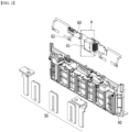
- FIG. 1 is a partial perspective view showing a conventional battery module.
- FIG. 2 is an exploded perspective view showing a busbar, a busbar frame, and a sensing member included in the battery module of FIG. 1 .
- FIG. 3 is a partial perspective view which enlarges and shows a section "A" of FIG. 2 .
- a conventional battery module 10 includes a battery cell stack 12 including a plurality of battery cells 11.
- the battery cell stack 12 can be housed inside the module frame, and for convenience of explanation, illustration of the module frame is omitted.
- a plurality of battery cells 11 are stacked in one direction, and a busbar 50 and a busbar frame 40 are disposed on one side of the battery cell stack 12 to electrically connect the battery cells 11.
- the busbar frame 40 may be located in the direction in which the electrode leads 13 of the battery cells 11 are located in the battery cell stack 12.
- a busbar 50 including a metal material may be mounted on such a busbar frame 40.
- the electrode leads 13 of the battery cells 11 may be weld-joined to the busbar 50.
- the electrode leads 13 of the battery cells 11 may be joined to the busbar 50, and electrically connected to each other in series or in parallel.
- the battery module 10 may include a sensing member 60. Voltage information of the battery cells 11 within the battery module 10 may be transmitted to an external battery management system (BMS) via such a sensing member 60.
- BMS battery management system
- the sensing member 60 includes an FFC (flat flexible cable), a PCB (printed circuit board), or an FPCB (flexible printed circuit board), wherein a module connector 61 may be connected to a sensing member 60, and a joining member 62 may be connected to one end of the sensing member 60.
- the plate-shaped joining member 62 may be joined to the busbar 50 to which the electrode lead 13 is joined by a welding method.
- Voltage information of each battery cell 11 may be transmitted to an external battery management system via the busbar 50, the joining member 62, the sensing member 60, and the module connector 61.
- the battery management system monitors and controls the condition of each battery cell 11 based on this.
- junction is performed using welding between the joining member 62 and the busbar 50, in which case there are problems that automation of the manufacturing process is difficult, the rework of junction is difficult, and non-destructive testing is impossible.
- a battery module comprising: a battery cell stack in which battery cells having electrode leads protruding in in either one or both directions are stacked; a busbar frame located on one side of the battery cell stack; a busbar and a sensing member mounted on the busbar frame; and a metal wire that connects the busbar and the sensing member, wherein the busbar includes a first metal layer located on a surface facing the busbar frame, and a second metal layer located on a surface opposite to a surface that faces the busbar frame, wherein the electrode lead passes through a slit formed in the busbar frame, and then is bent and joined to the second metal layer, and wherein one region of the metal wire is joined to the first metal layer, and the other region of the metal wire is connected to the sensing member.
- the metal wire and the busbar may be configured to be joined by wire bonding.
- the sensing member may include a FFC (flat flexible cable), a PCB (printed circuit board), or a FPCB (flexible printed circuit board).
- FFC flat flexible cable
- PCB printed circuit board
- FPCB flexible printed circuit board
- the first metal layer may include an aluminum material, and the second metal layer may include a copper material.
- the metal wire may include an aluminum material.
- a curved bending part may be formed on one side of the busbar.
- the first metal layer may be exposed to a surface opposite to a surface that faces the busbar frame.
- the metal wire may be joined to a portion exposed by the bending part among the first metal layer.
- a through hole is formed in the second metal layer, and the first metal layer may be exposed to a surface opposite to a surface that faces the busbar frame via the through hole.
- the metal wire may be joined to a portion exposed through the through hole among the first metal layer.
- the busbar may have a plate shape
- the first metal layer may have a thickness of 85% to 90% relative to the thickness of the busbar
- the second metal layer may have a thickness of 10% to 15% relative to the thickness of the busbar.
- a battery pack comprising the battery module.
- planar it means when a target portion is viewed from the upper side
- cross-sectional it means when a target portion is observed from the side of the vertically cut cross-section.
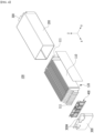
- FIG. 4 is an exploded perspective view showing a battery module according to an embodiment of the present disclosure.
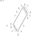
- FIG. 5 is a diagram showing one of the battery cells included in the battery module of FIG. 4 .
- the battery cell 110 is preferably a pouch-type battery cell, and can be formed in a rectangular sheet-like structure.
- the battery cell 110 according to the present embodiment has electrode leads 111 that protrude in in either one or both directions.
- FIG. 5 illustrates a structure in which two electrode leads 111 face each other and protrude from one end 114a and the other end 114b of the cell main body 113, respectively. More specifically, the electrode leads 111 are connected to an electrode assembly (not shown), and are protruded from the electrode assembly (not shown) to the outside of the battery cell 110.
- a battery cell in which two electrode leads 111 protrude in the same direction is also possible as an embodiment of the present disclosure.
- the battery cell 110 can be produced by joining both ends 114a and 114b of a cell case 114 and one side part 114c connecting them in a state in which an electrode assembly (not shown) is housed in a cell case 114.
- the battery cell 110 according to the present embodiment has a total of three sealing parts 114sa, 114sb and 114sc, wherein the sealing parts 114sa, 114sb and 114sc have a structure that is sealed by a method such as heat-sealing, and the remaining other side part may be composed of a folding part 115. It can form a structure in which the cell case 114 is folded in the folding part 115.
- the cell case 114 may be composed of a laminated sheet including a resin layer and a metal layer.
- the folding part 115 may extend long along one edge of the battery cell 110, and a protrusion 110p of the battery cell 110 called a bat-ear can be formed at an end part of the folding part 115.
- the protrusion 110p is an exemplary structure, and in another embodiment of the present disclosure, the battery cell 110 may have a configuration in which no protrusion is formed and the folding part 115 extends in a straight line.
- a terrace part 116 may be formed between the electrode leads 111 and the cell main body 113. That is, the battery cell 110 includes a terrace part 116 formed to extend from the cell main body 113 in the direction in which the electrode leads 111 protrude.
- the battery module 100 may include a module frame 200 and an end plate 300 that form an internal space in which the battery cell stack 120 is housed.
- the module frame 200 may be a structure in which one surface and the other surface opposite to the one surface are opened. More specifically, the module frame 200 may be opened in both directions where the electrode leads 111 protrude with respect to the battery cell stack 120.
- the module frame 200 may be in the form of a mono frame integrated with the upper surface, the lower surface and both side surfaces.
- the module frame 200 may include a U-shaped frame that covers the lower surface and both side surfaces of the battery cell stack 120 and an upper cover that covers the upper surface of the battery cell stack 120.
- the U-shaped frame and the upper cover may be joined with corresponding edges to form a module frame 200.
- the joining method is not particularly limited, and weld-joining may be performed as an example.
- the end plate 300 may be composed by a plurality of numbers, and may cover the one open surface and the other open surface of the module frame 200, respectively.
- the battery cell stack 120 is housed in the internal space formed by the module frame 200 and the end plate 300, so that the battery cell stack 120 can be physically protected.
- the module frame 200 and the end plate 300 may include a metal material with a predetermined strength.
- the module frame 200 and the end plate 300 may be joined by a method such as welding in a state where their corresponding edge portions are in contact with each other.
- busbar frame the busbar, the busbar, and the sensing member according to the present embodiment will be described in detail.
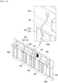
- FIG. 6 is a perspective view showing a busbar frame, a busbar, a sensing member, and the like included in the battery module of FIG. 4 .
- FIG. 7 is an exploded perspective view showing the busbar frame, busbar, sensing member, and the like in FIG. 6 .
- the busbar frame 400 is located on one side of the battery cell stack 120. Specifically, the busbar frame 400 may be located on one side in the direction in which the electrode lead 111 protrudes in the battery cell stack 120. In FIG. 4 , only the case where one busbar frame 400 is located on one side of the battery cell stack 120 is illustrated, but another busbar frame may be further located on the opposite side with respect to the battery cell stack 120. That is, a total of two busbar frames 400 may be disposed on both sides of the battery cell stack 120, respectively.
- the battery module 100 includes a busbar 500 and a sensing member 600 mounted on the busbar frame 400. Further, the battery module 100 includes a metal wire 700 that connects the busbar 500 and the sensing member 600.
- the busbar 500 is for electrically connecting the battery cells 110 within the battery module 100, and preferably includes a metal material to enable electrical connection.
- the busbar 500 may be mounted on a surface opposite to a surface that faces the battery cell stack 120 among the busbar frame 400.
- the electrode leads 111 protruding from the battery cells 110 may pass through a slit 400S formed in the busbar frame 400, and then be bent and connected to the busbar 500.
- one electrode lead 111 may pass through a slit 400S of the busbar frame 400 located on one side of the battery cell stack 120, and then be bent and connected to the busbar 500, and the other electrode lead 111 may pass through a slit in the busbar frame (not shown) located on the other side of the battery cell stack 120, and then be connected to the busbar 500.
- the connection method between the electrode lead 111 and the busbar 500 is not particularly limited, but weld-joining may be performed as an example. The connection between the electrode lead 111 and the busbar 500 will be described again with reference to FIG. 9 .
- the busbar frame 400 preferably includes an electrically insulating material in order to prevent the busbar 500 and other electrical components from coming into contact with parts other than the electrode lead 111 of the battery cell 110 and causing a short circuit.
- the busbar frame 400 may be an injection-molded plastic product.
- the busbar frame 400 may be equipped with a terminal busbar 500T in addition to the busbar 500.
- the terminal busbar 500T may be mounted on a surface opposite to a surface that faces the battery cell stack 120 among the busbar frame 400, and the electrode leads 111 may pass through a slit 400S formed in the busbar frame 400, and then be bent and connected to the terminal busbar 500T.
- the terminal busbar 500T is generally similar to the busbar 500, but unlike the busbar 500, it has a part exposed to the outside.
- a terminal opening hole 300H (see FIG. 4 ) may be formed in the end plate 300, and the upwardly extending portion of the terminal busbar 500T may pass through the terminal opening hole 300H and be exposed to the outside of the battery module 100.
- the terminal busbar 500T functions as an input/output terminal of the battery module 100 for HV (High Voltage) connection.
- HV connection refers to an electrical connection that requires relatively high voltage, such as the input/output terminal of a battery module.
- the battery module 100 according to the present embodiment can be connected to other battery module or a battery disconnect unit (BDU) that controls the electrical connection of the battery module through the exposed portion of the terminal busbar 500T.
- BDU battery disconnect unit
- the sensing member 600 is a member for LV (Low Voltage) connection of the battery module 100.
- the LV connection refers to electrical connections that require relatively low voltage, such as battery electrical components.
- the sensing member 600 senses voltage data or temperature data of the battery cells 110 included in the battery module 100, and transmits the sensed voltage data or temperature data to a battery management system (BMS) located outside the battery module 100.
- BMS battery management system
- the battery management system manages the voltage or temperature of the corresponding battery module 100 based on the transmitted voltage or temperature data.
- the sensing member 600 is electrically connected to the busbar 500 to which the electrode lead 111 is connected via a metal wire 700, which will be described later. Similar to the busbar 500, the sensing member 600 may be mounted on a surface opposite to a surface that faces the battery cell stack 120 among the busbar frame 400, and can be mounted in the upper region of the busbar frame 400.
- This sensing member 600 may include a FFC (flat flexible cable), a PCB (printed circuit board), or a FPCB (flexible printed circuit board).
- a module connector 610 may be connected to the sensing member 600.
- the module connector 610 is a member exposed to the outside of the battery module 100, and is connected to a battery management system (BMS) located outside the battery module 100, so that voltage data or temperature data measured by sensing member 600 can be transmitted to a battery management system.
- BMS battery management system
- the electrode lead 111 is joined to the busbar 500, and a metal wire 700 connects the busbar 500 and the sensing member 600. Specifically, one region of the metal wire 700 is connected to the busbar 500, and the other region of the metal wire 700 is connected to the sensing member 600.
- the metal wire 700 and the busbar 500 may be configured to be joined by wire bonding.
- the wire bonding is a bonding method mainly used in the semiconductor manufacturing process, and refers to a method of connecting an integrated circuit and a terminal with a thin wire made of metal.
- the wire bonding refers to a technique that uses metal wires and creates electrical interconnections with a combination of ultrasonic energy and pressure.
- connection method between the metal wire 700 and the sensing member 600 is not particularly limited as long as electrical connection is possible therebetween.
- the strength of the welded portion should be evaluated through destructive testing.
- wire bonding is performed, and at the same time, a predetermined force is applied to the metal wire 700, thereby making it possible to evaluate the bonding strength in a non-destructive state. Even if only a small force is applied to the metal wire 700 compared to the strength at which the metal wire 700 breaks, strength evaluation can be performed. This non-destructive testing allows for complete monitoring of the joints in real time during the process.
- FIG. 8 is a diagram showing a busbar according to an embodiment of the present disclosure.
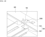
- FIG. 9 is a partial perspective view which enlarges and shows a section "B" of FIG. 6 .
- FIG. 10 is a partial view which enlarges and shows the connection form between the busbar and metal wire in FIG. 9 .
- FIG. 9 shows a state of the electrode lead 111 bent after passing through the slit 400S of the busbar frame 400.
- the busbar 500 includes a first metal layer 510 located on a surface facing the busbar frame 400 and a second metal layer 520 located on a surface opposite to a surface that faces the busbar frame 400.
- the second metal layer 520 is shown by shaded parts to facilitate distinction.
- the electrode lead 111 of the battery cell 110 passes through a slit 400S formed in the busbar frame 400, and then is bent and joined to the second metal layer 520.
- the metal wire 700 is joined to the first metal layer 510. That is, one region of the metal wire 700 is joined to the first metal layer 510, and the other region of the metal wire 700 is connected to the sensing member 600.
- the first metal layer 510 may include an aluminum material
- the second metal layer 520 may include a copper material
- the busbar 500 according to the present embodiment may be a clad member in which the first metal layer 510 and the second metal layer 520 are joined by rolling.
- the first metal layer 510 containing an aluminum material and the second metal layer 520 containing a copper material that is, the first and second metal layers 510 and 520 made of mutually different materials are joined to each other by rolling, so that a busbar 500 according to the present embodiment can be provided.
- clad joining for manufacturing a clad member refers to a technique of using a metal or non-metal as a base layer and joining the other metal to one surface of the base layer by rolling.
- the busbar 500 is mounted on the busbar frame 400 such that the first metal layer 510 faces the busbar frame 400 and the second metal layer 520 does not face the busbar frame 400.
- the second metal layer 520 is a region to which the electrode lead 111 that has passed through the slit 400S is bent and then joined. Since the capacity of battery cells gradually increases and charging time shortens, controlling the heat generation of battery cells is an important issue. In the case of copper, since it has excellent thermal and electrical conductivity, the degree of heat dissipation is excellent when applied to the busbar 500, which can improve the cooling performance of the battery module 100, and reduce the resistance in electrical connection with the electrode lead 111. That is, a copper material may be included in the second metal layer 520 of the busbar 500 in order to increase the degree of heat dissipation of the busbar 500 and reduce the resistance.
- a conventional busbar 50 may be constituted of a single layer of copper material.
- copper has excellent thermal and electrical conductivity, but has the disadvantage of being slightly expensive. Therefore, in the present embodiment, the busbar 500 is not constituted of a single layer of copper material, but is configured to include a first metal layer 510 and a second metal layer 520. Since the aluminum material included in the first metal layer 510 is about 3 to 4 times cheaper than the copper material included in the second metal layer 520, material costs can be reduced. Taken together, in order to simultaneously satisfy improvement of cooling performance, reduction of resistance, and reduction of costs, the busbar 500 according to the present embodiment was designed to include a first metal layer 510 containing an aluminum material and a second metal layer 520 containing a copper material.
- the first metal layer 510 containing an aluminum material may have a thickness of 85% or more and 90% or less relative to the thickness of the busbar 500
- the second metal layer 520 containing a copper material may have a thickness of 10% or more and 15% or less relative to the thickness of the bus bar 500.
- the manufacturing cost of the busbar 500 may be too high compared to the desired degree of heat dissipation of the busbar 500.
- the thickness of the first metal layer 510 is greater than 90% and the thickness of the second metal layer 520 is less than 10% relative to the thickness of the busbar 500, the extent of heat dissipation of the busbar 500 is insufficient, and thus, the battery module 100 may fail to satisfy the cooling performance standards.
- the metal wire 700 according to the present embodiment may include an aluminum material. That is, the metal wire 700 may include the same material as the material of the first metal layer 510 to which the metal wire 700 is joined.
- Aluminum material is widely used in the process of manufacturing battery modules and has the advantage of being inexpensive. Therefore, aluminum can be used as a material for the metal wire 700 for wire bonding.
- the bonding performance improves if the same materials are joined to each other, whereby the metal wire 700 containing an aluminum material was designed to be joined to a first metal layer 510 containing aluminum material.
- the second metal layer 520 is located on the surface opposite to the side that faces the busbar frame 400.
- the first metal layer 510 is located on the surface facing the busbar frame 400, in which case it may be difficult to join the first metal layer 510 and the metal wire 700 due to locational limitations.
- a curved bending part 500B was formed on one side of the busbar 500.
- the first metal layer 510 may be exposed to the surface opposite to the surface that faces the busbar frame 400.
- the bending part 500B may be a portion where both the first metal layer 510 and the second metal layer 520 of the busbar 500 are extended while being curved.
- the metal wire 700 may be joined to a portion of the first metal layer 510 exposed by the bending part 500B.
- the first metal layer 510 is included in the busbar 500 to reduce material costs and at the same time form a bending part 500B, so that the metal wire 700 is easily joined to the first metal layer 510 to thereby ensure manufacturing process performance.
- the position of the bending part 500B is not particularly limited, but it is preferably located close to the sensing member 600.
- a bending part 500B may be formed on the upper part of the busbar 500.
- a bending part 500B may be formed not only on the busbar 500 but also on the terminal busbar 500T, and the metal wire 700 may be joined to the first metal layer 510 of the bending portion 500B of the terminal busbar 500T.
- busbar according to another embodiment of the present disclosure will be described. However, descriptions of parts that overlap with those described above will be omitted.
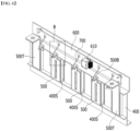
- FIG. 11 is a perspective view showing a busbar frame, a busbar, a sensing member, and the like according to another embodiment of the present disclosure.
- FIG. 12 is a diagram showing the busbar of FIG. 11 .
- the second metal layer 520 is shown by shaded parts to facilitate distinction.
- the busbar 500 and the sensing member 600 may be mounted on the busbar frame 400 according to another embodiment of the present disclosure.
- a metal wire 700 may connect the busbar 500 and the sensing member 600.
- a terminal busbar 500T can be mounted on the busbar frame 400, and the sensing member 600 may be connected to the module connector 610.
- the busbar 500 includes a first metal layer 510 located on the surface facing the busbar frame 400 and a second metal layer 520 located on the surface opposite to the surface that faces the busbar frame 400.
- the electrode lead 111 of the battery cell 110 passes through a slit formed in the busbar frame 400, and then is bent and joined to the second metal layer 520.
- the busbar 500 according to the present embodiment differs in that a through hole 520H is formed in the second metal layer 520 instead of the bending part.
- a through hole 520H may be formed in the second metal layer 520, and the first metal layer 510 may be exposed to the surface opposite to the surface that faces the busbar frame 400 through this through hole 520H.
- the metal wire 700 may be joined to a portion exposed through the through hole 520H among the first metal layer 510.
- the first metal layer 510 is included in the busbar 500 to save material costs
- the second metal layer 520 is formed with a through hole 520H, so that the metal wire 700 can be easily connected to the first metal layer 510, thereby ensuring manufacturing process performance.
- the position of the through hole 520H is not particularly limited, but it is preferably located close to the sensing member 600.
- a through hole 520H may be formed in the upper region of the busbar 500. Further, as shown in FIG. 11 , a through hole 520H may be formed not only in the busbar 500 but also in the terminal busbar 500T, and the metal wire 700 may be bonded to the first metal layer 510 exposed through the through hole 520H of the terminal busbar 500T.
- the one or more battery modules according to embodiments of the present disclosure described above can be mounted together with various control and protection systems such as a battery management system (BMS), a battery disconnect unit (BDU), and a cooling system to form a battery pack.
- BMS battery management system
- BDU battery disconnect unit
- the battery module or the battery pack can be applied to various devices. Specifically, it can be applied to vehicle means such as an electric bike, an electric vehicle, and a hybrid electric vehicle, or an ESS (energy storage system) and may be applied to various devices capable of using a secondary battery, without being limited thereto.
- vehicle means such as an electric bike, an electric vehicle, and a hybrid electric vehicle, or an ESS (energy storage system) and may be applied to various devices capable of using a secondary battery, without being limited thereto.
Landscapes
- Chemical & Material Sciences (AREA)
- Chemical Kinetics & Catalysis (AREA)
- Electrochemistry (AREA)
- General Chemical & Material Sciences (AREA)
- Engineering & Computer Science (AREA)
- Manufacturing & Machinery (AREA)
- Inorganic Chemistry (AREA)
- Microelectronics & Electronic Packaging (AREA)
- Connection Of Batteries Or Terminals (AREA)
- Battery Mounting, Suspending (AREA)
Abstract
Description
- This application claims the benefit of
Korean Patent Application No. 10-2022-0107418 filed on August 26, 2022 - The present disclosure relates to a battery module and a battery pack including the same, and more particularly, a battery module that improves manufacturing process efficiency and reduces costs, and a battery pack including the same.
- In modern society, as portable devices such as a mobile phone, a notebook computer, a camcorder and a digital camera has been daily used, the development of technologies in the fields related to mobile devices as described above has been activated. In addition, chargeable/dischargeable secondary batteries are used as a power source for an electric vehicle (EV), a hybrid electric vehicle (HEV), a plug-in hybrid electric vehicle (P-HEV) and the like, in an attempt to solve air pollution and the like caused by existing gasoline vehicles using fossil fuel. Therefore, the demand for development of the secondary battery is growing.
- Currently commercialized secondary batteries include a nickel cadmium battery, a nickel hydrogen battery, a nickel zinc battery, and a lithium secondary battery. Among them, the lithium secondary battery has come into the spotlight because it has advantages, for example, hardly exhibiting memory effects compared to nickel-based secondary batteries and thus being freely charged and discharged, and having very low self-discharge rate and high energy density.
- Such a lithium secondary battery mainly uses a lithium-based oxide and a carbonaceous material as a cathode active material and an anode active material, respectively. The lithium secondary battery includes an electrode assembly in which a cathode plate and an anode plate, each being coated with the cathode active material and the anode active material, are disposed with a separator being interposed therebetween, and an exterior material, i.e., a battery case, that seals and houses the electrode assembly together with the electrolyte.
- Generally, the lithium secondary battery may be classified into a can-type secondary battery in which the electrode assembly is mounted in a metal can, and a pouch-type secondary battery in which the electrode assembly is mounted in a pouch of an aluminum laminate sheet, depending on the shape of the exterior material.
- In the case of a secondary battery used for small-sized devices, two to three battery cells are disposed, but in the case of a secondary battery used for a medium- and large-sized device such as automobiles, a battery module in which a plurality of battery cells are electrically connected is used. In such a battery module, a plurality of battery cells are connected to each other in series or parallel to form a cell assembly, thereby improving capacity and output. One or more battery modules can be mounted together with various control and protection systems such as a battery management system (BMS), a battery disconnect unit (BDU), and a cooling system to form a battery pack.
-
FIG. 1 is a partial perspective view showing a conventional battery module.FIG. 2 is an exploded perspective view showing a busbar, a busbar frame, and a sensing member included in the battery module ofFIG. 1 .FIG. 3 is a partial perspective view which enlarges and shows a section "A" ofFIG. 2 . - Referring to
FIGS. 1 to 3 , aconventional battery module 10 includes abattery cell stack 12 including a plurality ofbattery cells 11. Thebattery cell stack 12 can be housed inside the module frame, and for convenience of explanation, illustration of the module frame is omitted. A plurality ofbattery cells 11 are stacked in one direction, and abusbar 50 and abusbar frame 40 are disposed on one side of thebattery cell stack 12 to electrically connect thebattery cells 11. - Specifically, the
busbar frame 40 may be located in the direction in which the electrode leads 13 of thebattery cells 11 are located in thebattery cell stack 12. Abusbar 50 including a metal material may be mounted on such abusbar frame 40. The electrode leads 13 of thebattery cells 11 may be weld-joined to thebusbar 50. The electrode leads 13 of thebattery cells 11 may be joined to thebusbar 50, and electrically connected to each other in series or in parallel. - The
battery module 10 may include asensing member 60. Voltage information of thebattery cells 11 within thebattery module 10 may be transmitted to an external battery management system (BMS) via such asensing member 60. - Specifically, the
sensing member 60 includes an FFC (flat flexible cable), a PCB (printed circuit board), or an FPCB (flexible printed circuit board), wherein amodule connector 61 may be connected to asensing member 60, and a joiningmember 62 may be connected to one end of thesensing member 60. The plate-shaped joiningmember 62 may be joined to thebusbar 50 to which theelectrode lead 13 is joined by a welding method. Voltage information of eachbattery cell 11 may be transmitted to an external battery management system via thebusbar 50, the joiningmember 62, thesensing member 60, and themodule connector 61. The battery management system monitors and controls the condition of eachbattery cell 11 based on this. - At this time, in the
conventional battery module 10, junction is performed using welding between the joiningmember 62 and thebusbar 50, in which case there are problems that automation of the manufacturing process is difficult, the rework of junction is difficult, and non-destructive testing is impossible. - It is an object of the present disclosure to provide a battery module that enables automation of the manufacturing process, rework of junction, and non-destructive testing in the connection between the sensing member and the busbar, and a battery pack including the same.
- However, the technical problems to be solved by embodiments of the present disclosure are not limited to the above-described problems, and can be variously expanded within the scope of the technical idea included in the present disclosure.
- According to one embodiment of the present disclosure, there is provided a battery module comprising: a battery cell stack in which battery cells having electrode leads protruding in in either one or both directions are stacked; a busbar frame located on one side of the battery cell stack; a busbar and a sensing member mounted on the busbar frame; and a metal wire that connects the busbar and the sensing member, wherein the busbar includes a first metal layer located on a surface facing the busbar frame, and a second metal layer located on a surface opposite to a surface that faces the busbar frame, wherein the electrode lead passes through a slit formed in the busbar frame, and then is bent and joined to the second metal layer, and wherein one region of the metal wire is joined to the first metal layer, and the other region of the metal wire is connected to the sensing member.
- The metal wire and the busbar may be configured to be joined by wire bonding.
- The sensing member may include a FFC (flat flexible cable), a PCB (printed circuit board), or a FPCB (flexible printed circuit board).
- The first metal layer may include an aluminum material, and the second metal layer may include a copper material.
- The metal wire may include an aluminum material.
- A curved bending part may be formed on one side of the busbar. In the bending part, the first metal layer may be exposed to a surface opposite to a surface that faces the busbar frame.
- The metal wire may be joined to a portion exposed by the bending part among the first metal layer.
- A through hole is formed in the second metal layer, and the first metal layer may be exposed to a surface opposite to a surface that faces the busbar frame via the through hole.
- The metal wire may be joined to a portion exposed through the through hole among the first metal layer.
- The busbar may have a plate shape, the first metal layer may have a thickness of 85% to 90% relative to the thickness of the busbar, and the second metal layer may have a thickness of 10% to 15% relative to the thickness of the busbar.
- The battery cell is a pouch-type battery cell, and the battery cells may be stacked in an upright state to form the battery cell stack.
- According to another embodiment of the present disclosure, there is provided a battery pack comprising the battery module.
- According to embodiments of the present disclosure, by applying a joining method using a metal wire when connecting between the sensing member and the busbar, automation of manufacturing processes, rework of junction, and non-destructive testing are all possible.
- Additionally, by including both copper material and aluminum material in the busbar, material costs can be reduced.
- The effects of the present disclosure are not limited to the effects mentioned above, and additional other effects not mentioned above will be clearly understood from the description of claims by those skilled in the art.
-
-
FIG. 1 is a partial perspective view showing a conventional battery module; -
FIG. 2 is an exploded perspective view showing a busbar, a busbar frame, and a sensing member included in the battery module ofFIG. 1 ; -
FIG. 3 is a partial perspective view which enlarges and shows a section "A" ofFIG. 2 ; -
FIG. 4 is an exploded perspective view showing a battery module according to an embodiment of the present disclosure; -
FIG. 5 is a diagram showing one of the battery cells included in the battery module ofFIG. 4 ; -
FIG. 6 is a perspective view showing a busbar frame, a busbar, a sensing member, and the like included in the battery module ofFIG. 4 ; -
FIG. 7 is an exploded perspective view showing the busbar frame, busbar, sensing member, and the like inFIG. 6 ; -
FIG. 8 is a diagram showing a busbar according to an embodiment of the present disclosure; -
FIG. 9 is a partial perspective view which enlarges and shows a section "B" ofFIG. 6 ; -
FIG. 10 is a partial view which enlarges and shows the connection form between the busbar and metal wire inFIG. 9 ; -
FIG. 11 is a perspective view showing a busbar frame, a busbar, a sensing member, and the like according to another embodiment of the present disclosure; and -
FIG. 12 is a diagram showing the busbar ofFIG. 11 . - Hereinafter, various embodiments of the present disclosure will be described in detail with reference to the accompanying drawings so that those skilled in the art can easily carry out them. The present disclosure may be modified in various different ways, and is not limited to the embodiments set forth herein.
- Portions that are irrelevant to the description will be omitted to clearly describe the present disclosure, and same reference numerals designate same or like elements throughout the description.
- Further, in the drawings, the size and thickness of each element are arbitrarily illustrated for convenience of description, and the present disclosure is not necessarily limited to those illustrated in the drawings. In the drawings, the thickness of layers, regions, etc. are exaggerated for clarity. In the drawings, for convenience of description, the thicknesses of a part and an area are exaggerated.
- Further, it will be understood that when an element such as a layer, film, region, or plate is referred to as being "on" or "above" another element, it can be directly on the other element or intervening elements may also be present. In contrast, when an element is referred to as being "directly on" another element, it means that other intervening elements are not present. Further, a certain part being located "above" or "on" a reference portion means the certain part being located above or below the reference portion and does not particularly mean the certain part "above" or "on" toward an opposite direction of gravity.
- Further, throughout the description, when a portion is referred to as "including" or "comprising" a certain component, it means that the portion can further include other components, without excluding the other components, unless otherwise stated.
- Further, throughout the description, when it is referred to as "planar", it means when a target portion is viewed from the upper side, and when it is referred to as "cross-sectional", it means when a target portion is observed from the side of the vertically cut cross-section.
-
FIG. 4 is an exploded perspective view showing a battery module according to an embodiment of the present disclosure.FIG. 5 is a diagram showing one of the battery cells included in the battery module ofFIG. 4 . - Referring to
FIGS. 4 and5 , thebattery module 100 according to an embodiment of the present disclosure includes abattery cell stack 120 in whichbattery cells 110 are stacked and abusbar frame 400 located on one side of thebattery cell stack 120. - First, the
battery cell 110 is preferably a pouch-type battery cell, and can be formed in a rectangular sheet-like structure. Thebattery cell 110 according to the present embodiment has electrode leads 111 that protrude in in either one or both directions. As an example,FIG. 5 illustrates a structure in which two electrode leads 111 face each other and protrude from oneend 114a and theother end 114b of the cellmain body 113, respectively. More specifically, the electrode leads 111 are connected to an electrode assembly (not shown), and are protruded from the electrode assembly (not shown) to the outside of thebattery cell 110. Although not specifically shown, a battery cell in which two electrode leads 111 protrude in the same direction is also possible as an embodiment of the present disclosure. - On the other hand, the
battery cell 110 can be produced by joining bothends cell case 114 and oneside part 114c connecting them in a state in which an electrode assembly (not shown) is housed in acell case 114. In other words, thebattery cell 110 according to the present embodiment has a total of three sealing parts 114sa, 114sb and 114sc, wherein the sealing parts 114sa, 114sb and 114sc have a structure that is sealed by a method such as heat-sealing, and the remaining other side part may be composed of afolding part 115. It can form a structure in which thecell case 114 is folded in thefolding part 115. Thecell case 114 may be composed of a laminated sheet including a resin layer and a metal layer. - Further, the
folding part 115 may extend long along one edge of thebattery cell 110, and aprotrusion 110p of thebattery cell 110 called a bat-ear can be formed at an end part of thefolding part 115. However, theprotrusion 110p is an exemplary structure, and in another embodiment of the present disclosure, thebattery cell 110 may have a configuration in which no protrusion is formed and thefolding part 115 extends in a straight line. - Further, while the
cell case 114 is sealed, with the protruding electrode leads 111 being interposed therebetween, aterrace part 116 may be formed between the electrode leads 111 and the cellmain body 113. That is, thebattery cell 110 includes aterrace part 116 formed to extend from the cellmain body 113 in the direction in which the electrode leads 111 protrude. - Such a
battery cell 110 may be composed by a plurality of numbers, and the plurality ofbattery cells 110 may be stacked so as to be electrically connected to each other, thereby forming abattery cell stack 120. Particularly, as shown inFIG. 4 , a plurality ofbattery cells 110 may be stacked in an upright state along a direction parallel to the y-axis so as to make one side surfaces of the cellmain body 113 face each other. Thereby, the electrode leads 111 may protrude in a direction perpendicular to the direction in which thebattery cells 110 are stacked. That is, in thebattery cell 110, oneelectrode lead 111 may protrude toward the x-axis direction, and theother electrode lead 111 may protrude toward the -x-axis direction. If the electrode leads 111 are battery cells that protrude only in one direction, the electrode leads 111 protrude in the x-axis direction or the -x-axis direction. - On the other hand, the
battery module 100 according to the present embodiment may include amodule frame 200 and anend plate 300 that form an internal space in which thebattery cell stack 120 is housed. - The
module frame 200 may be a structure in which one surface and the other surface opposite to the one surface are opened. More specifically, themodule frame 200 may be opened in both directions where the electrode leads 111 protrude with respect to thebattery cell stack 120. In an embodiment of the present disclosure, themodule frame 200 may be in the form of a mono frame integrated with the upper surface, the lower surface and both side surfaces. Further, in another embodiment of the present disclosure, themodule frame 200 may include a U-shaped frame that covers the lower surface and both side surfaces of thebattery cell stack 120 and an upper cover that covers the upper surface of thebattery cell stack 120. The U-shaped frame and the upper cover may be joined with corresponding edges to form amodule frame 200. The joining method is not particularly limited, and weld-joining may be performed as an example. - The
end plate 300 may be composed by a plurality of numbers, and may cover the one open surface and the other open surface of themodule frame 200, respectively. Thebattery cell stack 120 is housed in the internal space formed by themodule frame 200 and theend plate 300, so that thebattery cell stack 120 can be physically protected. For this purpose, themodule frame 200 and theend plate 300 may include a metal material with a predetermined strength. On the other hand, themodule frame 200 and theend plate 300 may be joined by a method such as welding in a state where their corresponding edge portions are in contact with each other. - Next, the busbar frame, the busbar, and the sensing member according to the present embodiment will be described in detail.
-
FIG. 6 is a perspective view showing a busbar frame, a busbar, a sensing member, and the like included in the battery module ofFIG. 4 .FIG. 7 is an exploded perspective view showing the busbar frame, busbar, sensing member, and the like inFIG. 6 . - Referring to
FIGS. 4 to 7 together, thebusbar frame 400 according to the present embodiment is located on one side of thebattery cell stack 120. Specifically, thebusbar frame 400 may be located on one side in the direction in which theelectrode lead 111 protrudes in thebattery cell stack 120. InFIG. 4 , only the case where onebusbar frame 400 is located on one side of thebattery cell stack 120 is illustrated, but another busbar frame may be further located on the opposite side with respect to thebattery cell stack 120. That is, a total of twobusbar frames 400 may be disposed on both sides of thebattery cell stack 120, respectively. - The
battery module 100 according to the present embodiment includes abusbar 500 and asensing member 600 mounted on thebusbar frame 400. Further, thebattery module 100 includes ametal wire 700 that connects thebusbar 500 and thesensing member 600. - The
busbar 500 is for electrically connecting thebattery cells 110 within thebattery module 100, and preferably includes a metal material to enable electrical connection. Thebusbar 500 may be mounted on a surface opposite to a surface that faces thebattery cell stack 120 among thebusbar frame 400. The electrode leads 111 protruding from thebattery cells 110 may pass through aslit 400S formed in thebusbar frame 400, and then be bent and connected to thebusbar 500. More specifically, oneelectrode lead 111 may pass through aslit 400S of thebusbar frame 400 located on one side of thebattery cell stack 120, and then be bent and connected to thebusbar 500, and theother electrode lead 111 may pass through a slit in the busbar frame (not shown) located on the other side of thebattery cell stack 120, and then be connected to thebusbar 500. The connection method between theelectrode lead 111 and thebusbar 500 is not particularly limited, but weld-joining may be performed as an example. The connection between theelectrode lead 111 and thebusbar 500 will be described again with reference toFIG. 9 . - By connecting the electrode leads 111 of the
battery cells 110 to thebusbar 500 as described above, electrical series or parallel connection between thebattery cells 110 can be realized. - On the other hand, the
busbar frame 400 preferably includes an electrically insulating material in order to prevent thebusbar 500 and other electrical components from coming into contact with parts other than theelectrode lead 111 of thebattery cell 110 and causing a short circuit. As an example, thebusbar frame 400 may be an injection-molded plastic product. - On the other hand, the
busbar frame 400 may be equipped with aterminal busbar 500T in addition to thebusbar 500. Similar to thebusbar 500, theterminal busbar 500T may be mounted on a surface opposite to a surface that faces thebattery cell stack 120 among thebusbar frame 400, and the electrode leads 111 may pass through aslit 400S formed in thebusbar frame 400, and then be bent and connected to theterminal busbar 500T. Theterminal busbar 500T is generally similar to thebusbar 500, but unlike thebusbar 500, it has a part exposed to the outside. As an example, aterminal opening hole 300H (seeFIG. 4 ) may be formed in theend plate 300, and the upwardly extending portion of theterminal busbar 500T may pass through theterminal opening hole 300H and be exposed to the outside of thebattery module 100. - The
terminal busbar 500T functions as an input/output terminal of thebattery module 100 for HV (High Voltage) connection. HV connection refers to an electrical connection that requires relatively high voltage, such as the input/output terminal of a battery module. Thebattery module 100 according to the present embodiment can be connected to other battery module or a battery disconnect unit (BDU) that controls the electrical connection of the battery module through the exposed portion of theterminal busbar 500T. - The sensing
member 600 is a member for LV (Low Voltage) connection of thebattery module 100. The LV connection refers to electrical connections that require relatively low voltage, such as battery electrical components. As an example, the sensingmember 600 senses voltage data or temperature data of thebattery cells 110 included in thebattery module 100, and transmits the sensed voltage data or temperature data to a battery management system (BMS) located outside thebattery module 100. The battery management system manages the voltage or temperature of thecorresponding battery module 100 based on the transmitted voltage or temperature data. - In order to sense the voltage data of the
battery cell 110, the sensingmember 600 is electrically connected to thebusbar 500 to which theelectrode lead 111 is connected via ametal wire 700, which will be described later. Similar to thebusbar 500, the sensingmember 600 may be mounted on a surface opposite to a surface that faces thebattery cell stack 120 among thebusbar frame 400, and can be mounted in the upper region of thebusbar frame 400. Thissensing member 600 may include a FFC (flat flexible cable), a PCB (printed circuit board), or a FPCB (flexible printed circuit board). - A
module connector 610 may be connected to thesensing member 600. Themodule connector 610 is a member exposed to the outside of thebattery module 100, and is connected to a battery management system (BMS) located outside thebattery module 100, so that voltage data or temperature data measured by sensingmember 600 can be transmitted to a battery management system. - As described above, the
electrode lead 111 is joined to thebusbar 500, and ametal wire 700 connects thebusbar 500 and thesensing member 600. Specifically, one region of themetal wire 700 is connected to thebusbar 500, and the other region of themetal wire 700 is connected to thesensing member 600. - At this time, the
metal wire 700 and thebusbar 500 may be configured to be joined by wire bonding. The wire bonding is a bonding method mainly used in the semiconductor manufacturing process, and refers to a method of connecting an integrated circuit and a terminal with a thin wire made of metal. In other words, the wire bonding refers to a technique that uses metal wires and creates electrical interconnections with a combination of ultrasonic energy and pressure. - On the other hand, the connection method between the
metal wire 700 and thesensing member 600 is not particularly limited as long as electrical connection is possible therebetween. - Similar to
FIGS. 2 and3 , when connecting the sensingmember 60 and thebusbar 50 in aconventional battery module 10, a method was used in which a joiningmember 62, which is a plate-shaped metal member, is welded to thebusbar 50. In particular, resistance welding, ultrasonic welding, or laser welding were applied. On the other hand, in thebattery module 100 according to the present embodiment, wire bonding using ametal wire 700 is applied when connecting thesensing member 600 and thebusbar 500. Below, the advantages of thebattery module 100 of the present disclosure over theconventional battery module 10 will be described from the viewpoints of automation of the manufacturing process, rework of junction, and non-destructive testing. - First, in the process of joining between the joining
member 62 and thebusbar 50 of theconventional battery module 10, there must be no gap between the joiningmember 62 and thebusbar 50 to ensure the strength of the welded joint. In order to eliminate the gap, clamping work on the sensingmember 60 is first performed, but due to the flexible nature of the sensingmember 60, it is difficult to secure the sensingmember 60 during a clamping operation. Therefore, the clamping work is difficult to automate and must be performed manually. On the other hand, when using themetal wire 700 as in the present embodiment, the two connection objects can be joined even if they are at different lengths, different directions, and different heights, so the conventional gap problem can be solved, and automation of the manufacturing process is possible. - Next, when a weld-joining such as laser welding is applied between the joining
member 62 and thebusbar 50, chemical deformation occurs in both metal materials. Therefore, when rework is performed, welding must be performed in other regions of the jointingmember 62 that has not been welded, and since the region is not large, rework is not easy. On the other hand, in the case of wire bonding using ametal wire 700, rework is easy because no chemical reaction occurs on the surface of the metal material. Further, in the case of wire bonding, there is an advantage that rework can be performed if only a very narrow region can be secured. - Finally, when a weldjoining such as laser welding is applied between the joining
member 62 and thebusbar 50, the strength of the welded portion should be evaluated through destructive testing. On the other hand, in the case of wire bonding using themetal wire 700, wire bonding is performed, and at the same time, a predetermined force is applied to themetal wire 700, thereby making it possible to evaluate the bonding strength in a non-destructive state. Even if only a small force is applied to themetal wire 700 compared to the strength at which themetal wire 700 breaks, strength evaluation can be performed. This non-destructive testing allows for complete monitoring of the joints in real time during the process. - Below, a specific form of the busbar according to the present embodiment will be described in detail.
-
FIG. 8 is a diagram showing a busbar according to an embodiment of the present disclosure.FIG. 9 is a partial perspective view which enlarges and shows a section "B" ofFIG. 6 .FIG. 10 is a partial view which enlarges and shows the connection form between the busbar and metal wire inFIG. 9 . However, for convenience of explanation,FIG. 9 shows a state of theelectrode lead 111 bent after passing through theslit 400S of thebusbar frame 400. - Referring to
FIGS. 8 to 10 together withFIGS. 4 and6 , thebusbar 500 according to the present embodiment includes afirst metal layer 510 located on a surface facing thebusbar frame 400 and asecond metal layer 520 located on a surface opposite to a surface that faces thebusbar frame 400. InFIG. 8 , thesecond metal layer 520 is shown by shaded parts to facilitate distinction. - The
electrode lead 111 of thebattery cell 110 passes through aslit 400S formed in thebusbar frame 400, and then is bent and joined to thesecond metal layer 520. Themetal wire 700 is joined to thefirst metal layer 510. That is, one region of themetal wire 700 is joined to thefirst metal layer 510, and the other region of themetal wire 700 is connected to thesensing member 600. - The
first metal layer 510 may include an aluminum material, and thesecond metal layer 520 may include a copper material. Specifically, thebusbar 500 according to the present embodiment may be a clad member in which thefirst metal layer 510 and thesecond metal layer 520 are joined by rolling. As an example, thefirst metal layer 510 containing an aluminum material and thesecond metal layer 520 containing a copper material, that is, the first andsecond metal layers busbar 500 according to the present embodiment can be provided. Here, clad joining for manufacturing a clad member refers to a technique of using a metal or non-metal as a base layer and joining the other metal to one surface of the base layer by rolling. This is a joining technique that allows the characteristics of each material to appear at the same time. That is, thefirst metal layer 510 and thesecond metal layer 520 can be joined to each other using a clad bonding technique to form thebusbar 500 according to the present embodiment. Thebusbar 500 is mounted on thebusbar frame 400 such that thefirst metal layer 510 faces thebusbar frame 400 and thesecond metal layer 520 does not face thebusbar frame 400. - The
second metal layer 520 is a region to which theelectrode lead 111 that has passed through theslit 400S is bent and then joined. Since the capacity of battery cells gradually increases and charging time shortens, controlling the heat generation of battery cells is an important issue. In the case of copper, since it has excellent thermal and electrical conductivity, the degree of heat dissipation is excellent when applied to thebusbar 500, which can improve the cooling performance of thebattery module 100, and reduce the resistance in electrical connection with theelectrode lead 111. That is, a copper material may be included in thesecond metal layer 520 of thebusbar 500 in order to increase the degree of heat dissipation of thebusbar 500 and reduce the resistance. - On the other hand, a
conventional busbar 50 may be constituted of a single layer of copper material. However, copper has excellent thermal and electrical conductivity, but has the disadvantage of being slightly expensive. Therefore, in the present embodiment, thebusbar 500 is not constituted of a single layer of copper material, but is configured to include afirst metal layer 510 and asecond metal layer 520. Since the aluminum material included in thefirst metal layer 510 is about 3 to 4 times cheaper than the copper material included in thesecond metal layer 520, material costs can be reduced. Taken together, in order to simultaneously satisfy improvement of cooling performance, reduction of resistance, and reduction of costs, thebusbar 500 according to the present embodiment was designed to include afirst metal layer 510 containing an aluminum material and asecond metal layer 520 containing a copper material. - At this time, in the plate-shaped
busbar 500, thefirst metal layer 510 containing an aluminum material may have a thickness of 85% or more and 90% or less relative to the thickness of thebusbar 500, and thesecond metal layer 520 containing a copper material may have a thickness of 10% or more and 15% or less relative to the thickness of thebus bar 500. - When the thickness of the
first metal layer 510 is less than 85% and the thickness of thesecond metal layer 520 is more than 15% relative to the thickness of thebusbar 500, the manufacturing cost of thebusbar 500 may be too high compared to the desired degree of heat dissipation of thebusbar 500. - Further, when the thickness of the
first metal layer 510 is greater than 90% and the thickness of thesecond metal layer 520 is less than 10% relative to the thickness of thebusbar 500, the extent of heat dissipation of thebusbar 500 is insufficient, and thus, thebattery module 100 may fail to satisfy the cooling performance standards. - On the other hand, the
metal wire 700 according to the present embodiment may include an aluminum material. That is, themetal wire 700 may include the same material as the material of thefirst metal layer 510 to which themetal wire 700 is joined. Aluminum material is widely used in the process of manufacturing battery modules and has the advantage of being inexpensive. Therefore, aluminum can be used as a material for themetal wire 700 for wire bonding. - In wire bonding between the
metal wire 700 and thebusbar 500, the bonding performance improves if the same materials are joined to each other, whereby themetal wire 700 containing an aluminum material was designed to be joined to afirst metal layer 510 containing aluminum material. - However, because the
second metal layer 520 must be joined to theelectrode lead 111, thesecond metal layer 520 is located on the surface opposite to the side that faces thebusbar frame 400. Thefirst metal layer 510 is located on the surface facing thebusbar frame 400, in which case it may be difficult to join thefirst metal layer 510 and themetal wire 700 due to locational limitations. - Therefore, in the present embodiment, a
curved bending part 500B was formed on one side of thebusbar 500. In thisbending part 500B, thefirst metal layer 510 may be exposed to the surface opposite to the surface that faces thebusbar frame 400. The bendingpart 500B may be a portion where both thefirst metal layer 510 and thesecond metal layer 520 of thebusbar 500 are extended while being curved. - As shown in
FIGS. 9 and10 , themetal wire 700 may be joined to a portion of thefirst metal layer 510 exposed by the bendingpart 500B. In the present embodiment, thefirst metal layer 510 is included in thebusbar 500 to reduce material costs and at the same time form abending part 500B, so that themetal wire 700 is easily joined to thefirst metal layer 510 to thereby ensure manufacturing process performance. - The position of the bending
part 500B is not particularly limited, but it is preferably located close to thesensing member 600. In one example, a bendingpart 500B may be formed on the upper part of thebusbar 500. In addition, as shown inFIGS. 6 and7 , a bendingpart 500B may be formed not only on thebusbar 500 but also on theterminal busbar 500T, and themetal wire 700 may be joined to thefirst metal layer 510 of the bendingportion 500B of theterminal busbar 500T. - Next, a busbar according to another embodiment of the present disclosure will be described. However, descriptions of parts that overlap with those described above will be omitted.
-
FIG. 11 is a perspective view showing a busbar frame, a busbar, a sensing member, and the like according to another embodiment of the present disclosure.FIG. 12 is a diagram showing the busbar ofFIG. 11 . InFIG. 12 , thesecond metal layer 520 is shown by shaded parts to facilitate distinction. - Referring to
FIGS. 11 and12 , thebusbar 500 and thesensing member 600 may be mounted on thebusbar frame 400 according to another embodiment of the present disclosure. Ametal wire 700 may connect thebusbar 500 and thesensing member 600. Aterminal busbar 500T can be mounted on thebusbar frame 400, and thesensing member 600 may be connected to themodule connector 610. - Further, the
busbar 500 includes afirst metal layer 510 located on the surface facing thebusbar frame 400 and asecond metal layer 520 located on the surface opposite to the surface that faces thebusbar frame 400. Theelectrode lead 111 of thebattery cell 110 passes through a slit formed in thebusbar frame 400, and then is bent and joined to thesecond metal layer 520. - Up to this point, it is similar to the structure of the busbar described previously in
FIGS. 8 to 10 . However, thebusbar 500 according to the present embodiment differs in that a throughhole 520H is formed in thesecond metal layer 520 instead of the bending part. - Specifically, a through
hole 520H may be formed in thesecond metal layer 520, and thefirst metal layer 510 may be exposed to the surface opposite to the surface that faces thebusbar frame 400 through this throughhole 520H. Themetal wire 700 may be joined to a portion exposed through the throughhole 520H among thefirst metal layer 510. In the present embodiment, thefirst metal layer 510 is included in thebusbar 500 to save material costs, and thesecond metal layer 520 is formed with a throughhole 520H, so that themetal wire 700 can be easily connected to thefirst metal layer 510, thereby ensuring manufacturing process performance. - The position of the through
hole 520H is not particularly limited, but it is preferably located close to thesensing member 600. In one example, a throughhole 520H may be formed in the upper region of thebusbar 500. Further, as shown inFIG. 11 , a throughhole 520H may be formed not only in thebusbar 500 but also in theterminal busbar 500T, and themetal wire 700 may be bonded to thefirst metal layer 510 exposed through the throughhole 520H of theterminal busbar 500T. - The terms representing directions such as the front side, the rear side, the left side, the right side, the upper side, and the lower side have been used in the present embodiment, but the terms used are provided simply for convenience of description and may become different according to the position of an object, the position of an observer, or the like.
- The one or more battery modules according to embodiments of the present disclosure described above can be mounted together with various control and protection systems such as a battery management system (BMS), a battery disconnect unit (BDU), and a cooling system to form a battery pack.
- The battery module or the battery pack can be applied to various devices. Specifically, it can be applied to vehicle means such as an electric bike, an electric vehicle, and a hybrid electric vehicle, or an ESS (energy storage system) and may be applied to various devices capable of using a secondary battery, without being limited thereto.
- The invention has been described in detail with reference to preferred embodiments thereof. However, it will be appreciated by those skilled in the art that the scope of the present disclosure is not limited thereto, and various modifications and improvements can be made in these embodiment without departing from the principles and sprit of the invention, the scope of which is defined in the appended claims and their equivalents.
-
- 100: battery module
- 110: battery cell
- 120: battery cell stack
- 400: busbar frame
- 500: busbar
- 500B: bending part
- 510: first metal layer
- 520: second metal layer
- 520H: through hole
- 600: sensing member
- 700: metal wire
Claims (12)
- A battery module comprising:a battery cell stack in which battery cells having electrode leads protruding in in either one or both directions are stacked;a busbar frame located on one side of the battery cell stack;a busbar and a sensing member mounted on the busbar frame; anda metal wire that connects the busbar and the sensing member,wherein the busbar includes a first metal layer located on a surface facing the busbar frame, and a second metal layer located on a surface opposite to a surface that faces the busbar frame,wherein the electrode lead passes through a slit formed in the busbar frame, and then is bent and joined to the second metal layer, andwherein one region of the metal wire is joined to the first metal layer, and the other region of the metal wire is connected to the sensing member.
- The battery module of claim 1, wherein:
the metal wire and the busbar are configured to be joined by wire bonding. - The battery module of claim 1, wherein:
the sensing member includes a FFC (flat flexible cable), a PCB (printed circuit board), or a FPCB (flexible printed circuit board). - The battery module of claim 1, wherein:
the first metal layer includes an aluminum material, and the second metal layer includes a copper material. - The battery module of claim 4, wherein:
the metal wire includes an aluminum material. - The battery module of claim 1, wherein:a curved bending part is formed on one side of the busbar, andin the bending part, the first metal layer is exposed to a surface opposite to a surface that faces the busbar frame.
- The battery module of claim 6, wherein:
the metal wire is joined to a portion exposed by the bending part among the first metal layer. - The battery module of claim 1, wherein:
a through hole is formed in the second metal layer, and the first metal layer is exposed to a surface opposite to a surface that faces the busbar frame via the through hole. - The battery module of claim 8, wherein:
the metal wire is joined to a portion exposed through the through hole among the first metal layer. - The battery module of claim 1, wherein:the busbar has a plate shape,the first metal layer has a thickness of 85% to 90% relative to the thickness of the busbar, andthe second metal layer has a thickness of 10% to 15% relative to the thickness of the busbar.
- The battery module of claim 1, wherein:the battery cell is a pouch-type battery cell, andthe battery cells are stacked in an upright state to form the battery cell stack.
- A battery pack comprising the battery module of claim 1.
Applications Claiming Priority (2)
| Application Number | Priority Date | Filing Date | Title |
|---|---|---|---|
| KR1020220107418A KR20240029225A (en) | 2022-08-26 | 2022-08-26 | Battery module and battery pack including the same |
| PCT/KR2023/011802 WO2024043586A1 (en) | 2022-08-26 | 2023-08-10 | Battery module and battery pack including same |
Publications (2)
| Publication Number | Publication Date |
|---|---|
| EP4435958A1 true EP4435958A1 (en) | 2024-09-25 |
| EP4435958A4 EP4435958A4 (en) | 2025-04-16 |
Family
ID=90013490
Family Applications (1)
| Application Number | Title | Priority Date | Filing Date |
|---|---|---|---|
| EP23857620.1A Pending EP4435958A4 (en) | 2022-08-26 | 2023-08-10 | BATTERY MODULE AND BATTERY PACK COMPRISING SAME |
Country Status (6)
| Country | Link |
|---|---|
| US (1) | US20250062512A1 (en) |
| EP (1) | EP4435958A4 (en) |
| JP (1) | JP7718779B2 (en) |
| KR (1) | KR20240029225A (en) |
| CN (1) | CN118355556A (en) |
| WO (1) | WO2024043586A1 (en) |
Families Citing this family (3)
| Publication number | Priority date | Publication date | Assignee | Title |
|---|---|---|---|---|
| WO2026005367A1 (en) * | 2024-06-24 | 2026-01-02 | 주식회사 엘지에너지솔루션 | Bus bar bonding plate for battery module and battery module comprising same |
| KR20260004016A (en) * | 2024-07-01 | 2026-01-08 | 주식회사 엘지에너지솔루션 | Busbar frame assembly and battery module including the same |
| KR20260017205A (en) * | 2024-07-29 | 2026-02-05 | 주식회사 엘지에너지솔루션 | Battery cell assembly and battery pack including the same |
Family Cites Families (9)
| Publication number | Priority date | Publication date | Assignee | Title |
|---|---|---|---|---|
| DE102014213275A1 (en) * | 2014-07-09 | 2016-01-14 | Robert Bosch Gmbh | Carrier assembly for carrying and holding components for battery cells of a battery module, in particular for an electric vehicle |
| JP2019114389A (en) * | 2017-12-22 | 2019-07-11 | ダイムラー・アクチェンゲゼルシャフトDaimler AG | Battery module |
| EP4030548A4 (en) * | 2019-12-20 | 2022-11-23 | Lg Energy Solution, Ltd. | SUB-BLOCK INCLUDING MULTIPLE UNIT MODULES AND BMS ASSEMBLY, AND BATTERY PACK INCLUDING SUB-BLOCK |
| KR102847235B1 (en) * | 2020-06-17 | 2025-08-14 | 주식회사 엘지에너지솔루션 | Battery module with non-welded structure as a connection structure between a busbar and a voltage sensing member |
| JP2022014957A (en) * | 2020-07-08 | 2022-01-21 | 株式会社オートネットワーク技術研究所 | Battery wiring module |
| KR20220040199A (en) * | 2020-09-23 | 2022-03-30 | 주식회사 엘지에너지솔루션 | Battery module and battery pack including the same |
| KR20220041429A (en) * | 2020-09-25 | 2022-04-01 | 주식회사 엘지에너지솔루션 | Battery module and battery pack including the same |
| KR20220107418A (en) | 2021-01-25 | 2022-08-02 | 김예련 | Manufacturing method of mist spray type oil composition |
| KR102511924B1 (en) * | 2021-02-10 | 2023-03-20 | 삼성에스디아이 주식회사 | Battery pack |
-
2022
- 2022-08-26 KR KR1020220107418A patent/KR20240029225A/en active Pending
-
2023
- 2023-08-10 WO PCT/KR2023/011802 patent/WO2024043586A1/en not_active Ceased
- 2023-08-10 CN CN202380014880.5A patent/CN118355556A/en active Pending
- 2023-08-10 JP JP2024529742A patent/JP7718779B2/en active Active
- 2023-08-10 US US18/715,476 patent/US20250062512A1/en active Pending
- 2023-08-10 EP EP23857620.1A patent/EP4435958A4/en active Pending
Also Published As
| Publication number | Publication date |
|---|---|
| EP4435958A4 (en) | 2025-04-16 |
| CN118355556A (en) | 2024-07-16 |
| KR20240029225A (en) | 2024-03-05 |
| JP7718779B2 (en) | 2025-08-05 |
| JP2024542223A (en) | 2024-11-13 |
| US20250062512A1 (en) | 2025-02-20 |
| WO2024043586A1 (en) | 2024-02-29 |
Similar Documents
| Publication | Publication Date | Title |
|---|---|---|
| US20250062512A1 (en) | Battery module and battery pack including the same | |
| JP7134543B2 (en) | Electrode assembly including plastic member applied to electrode tab lead connection and secondary battery including the same | |
| JP7596525B2 (en) | Battery module and manufacturing method thereof | |
| JP7434572B2 (en) | Battery module, battery pack including the same, and manufacturing method thereof | |
| KR20220120512A (en) | Battery module and manufacturing method of the same | |
| JP7546678B2 (en) | Battery module, battery pack including same, and method of manufacturing same | |
| KR102543155B1 (en) | Busbar frame and battery module having the same | |
| KR20220067119A (en) | Battery module and battery pack including the same | |
| EP4250463B1 (en) | Battery module and battery pack comprising same | |
| US20250329888A1 (en) | Battery module and battery pack including the same | |
| US20240039125A1 (en) | Battery module and battery pack including the same | |
| CN218919099U (en) | Battery module and battery pack | |
| US20260045647A1 (en) | Battery Cell and Battery Module Including the Same | |
| KR102523946B1 (en) | Busbar frame and battery module having the same | |
| JP2026507683A (en) | Busbar and battery module including same | |
| CN117957711A (en) | Battery Module | |
| KR20250157611A (en) | Busbar frame assembly and battery module including the same |
Legal Events
| Date | Code | Title | Description |
|---|---|---|---|
| STAA | Information on the status of an ep patent application or granted ep patent |
Free format text: STATUS: THE INTERNATIONAL PUBLICATION HAS BEEN MADE |
|
| PUAI | Public reference made under article 153(3) epc to a published international application that has entered the european phase |
Free format text: ORIGINAL CODE: 0009012 |
|
| STAA | Information on the status of an ep patent application or granted ep patent |
Free format text: STATUS: REQUEST FOR EXAMINATION WAS MADE |
|
| 17P | Request for examination filed |
Effective date: 20240618 |
|
| AK | Designated contracting states |
Kind code of ref document: A1 Designated state(s): AL AT BE BG CH CY CZ DE DK EE ES FI FR GB GR HR HU IE IS IT LI LT LU LV MC ME MK MT NL NO PL PT RO RS SE SI SK SM TR |
|
| A4 | Supplementary search report drawn up and despatched |
Effective date: 20250319 |
|
| RIC1 | Information provided on ipc code assigned before grant |
Ipc: H01M 50/50 20210101ALI20250313BHEP Ipc: H01M 50/105 20210101ALI20250313BHEP Ipc: H01M 10/48 20060101ALI20250313BHEP Ipc: H01M 10/42 20060101ALI20250313BHEP Ipc: H01M 50/211 20210101ALI20250313BHEP Ipc: H01M 50/519 20210101ALI20250313BHEP Ipc: H01M 50/569 20210101ALI20250313BHEP Ipc: H01M 50/507 20210101AFI20250313BHEP |
|
| STAA | Information on the status of an ep patent application or granted ep patent |
Free format text: STATUS: EXAMINATION IS IN PROGRESS |
|
| DAV | Request for validation of the european patent (deleted) | ||
| DAX | Request for extension of the european patent (deleted) | ||
| 17Q | First examination report despatched |
Effective date: 20251111 |