EP4435919A1 - Vehicular battery pack and related assembly method - Google Patents
Vehicular battery pack and related assembly method Download PDFInfo
- Publication number
- EP4435919A1 EP4435919A1 EP24164374.1A EP24164374A EP4435919A1 EP 4435919 A1 EP4435919 A1 EP 4435919A1 EP 24164374 A EP24164374 A EP 24164374A EP 4435919 A1 EP4435919 A1 EP 4435919A1
- Authority
- EP
- European Patent Office
- Prior art keywords
- battery pack
- substrate
- seats
- primary
- seat
- Prior art date
- Legal status (The legal status is an assumption and is not a legal conclusion. Google has not performed a legal analysis and makes no representation as to the accuracy of the status listed.)
- Pending
Links
- 238000000034 method Methods 0.000 title claims description 26
- 239000000758 substrate Substances 0.000 claims abstract description 48
- 230000000295 complement effect Effects 0.000 claims abstract description 5
- 238000004519 manufacturing process Methods 0.000 claims description 12
- 238000004804 winding Methods 0.000 claims description 12
- 239000003792 electrolyte Substances 0.000 claims description 8
- 239000000654 additive Substances 0.000 claims description 6
- 230000000996 additive effect Effects 0.000 claims description 6
- 238000005057 refrigeration Methods 0.000 claims description 5
- 238000005266 casting Methods 0.000 claims description 3
- 239000004020 conductor Substances 0.000 claims description 2
- 239000012777 electrically insulating material Substances 0.000 claims description 2
- 239000012466 permeate Substances 0.000 claims description 2
- 239000011245 gel electrolyte Substances 0.000 claims 1
- 238000007639 printing Methods 0.000 claims 1
- 229910052751 metal Inorganic materials 0.000 description 5
- 239000002184 metal Substances 0.000 description 5
- 239000011149 active material Substances 0.000 description 4
- 239000000463 material Substances 0.000 description 4
- 239000004411 aluminium Substances 0.000 description 3
- 229910052782 aluminium Inorganic materials 0.000 description 3
- XAGFODPZIPBFFR-UHFFFAOYSA-N aluminium Chemical compound [Al] XAGFODPZIPBFFR-UHFFFAOYSA-N 0.000 description 3
- 230000015572 biosynthetic process Effects 0.000 description 3
- 229910001416 lithium ion Inorganic materials 0.000 description 3
- WHXSMMKQMYFTQS-UHFFFAOYSA-N Lithium Chemical compound [Li] WHXSMMKQMYFTQS-UHFFFAOYSA-N 0.000 description 2
- HBBGRARXTFLTSG-UHFFFAOYSA-N Lithium ion Chemical compound [Li+] HBBGRARXTFLTSG-UHFFFAOYSA-N 0.000 description 2
- 229910000831 Steel Inorganic materials 0.000 description 2
- 238000001816 cooling Methods 0.000 description 2
- 238000003780 insertion Methods 0.000 description 2
- 230000037431 insertion Effects 0.000 description 2
- 229910052744 lithium Inorganic materials 0.000 description 2
- 229920000642 polymer Polymers 0.000 description 2
- 239000010959 steel Substances 0.000 description 2
- RYGMFSIKBFXOCR-UHFFFAOYSA-N Copper Chemical compound [Cu] RYGMFSIKBFXOCR-UHFFFAOYSA-N 0.000 description 1
- 230000000712 assembly Effects 0.000 description 1
- 238000000429 assembly Methods 0.000 description 1
- 239000000919 ceramic Substances 0.000 description 1
- 238000002485 combustion reaction Methods 0.000 description 1
- 229910052802 copper Inorganic materials 0.000 description 1
- 239000010949 copper Substances 0.000 description 1
- 230000001419 dependent effect Effects 0.000 description 1
- 230000008021 deposition Effects 0.000 description 1
- 238000007599 discharging Methods 0.000 description 1
- 239000011888 foil Substances 0.000 description 1
- 230000014509 gene expression Effects 0.000 description 1
- 239000011244 liquid electrolyte Substances 0.000 description 1
- 238000003801 milling Methods 0.000 description 1
- 239000012768 molten material Substances 0.000 description 1
- 238000005457 optimization Methods 0.000 description 1
- 239000005518 polymer electrolyte Substances 0.000 description 1
- 239000011347 resin Substances 0.000 description 1
- 229920005989 resin Polymers 0.000 description 1
- 238000000110 selective laser sintering Methods 0.000 description 1
- 238000000926 separation method Methods 0.000 description 1
- 239000007787 solid Substances 0.000 description 1
- 238000003860 storage Methods 0.000 description 1
Images

Classifications
-
- H—ELECTRICITY
- H01—ELECTRIC ELEMENTS
- H01M—PROCESSES OR MEANS, e.g. BATTERIES, FOR THE DIRECT CONVERSION OF CHEMICAL ENERGY INTO ELECTRICAL ENERGY
- H01M50/00—Constructional details or processes of manufacture of the non-active parts of electrochemical cells other than fuel cells, e.g. hybrid cells
- H01M50/10—Primary casings; Jackets or wrappings
- H01M50/102—Primary casings; Jackets or wrappings characterised by their shape or physical structure
- H01M50/112—Monobloc comprising multiple compartments
-
- H—ELECTRICITY
- H01—ELECTRIC ELEMENTS
- H01M—PROCESSES OR MEANS, e.g. BATTERIES, FOR THE DIRECT CONVERSION OF CHEMICAL ENERGY INTO ELECTRICAL ENERGY
- H01M50/00—Constructional details or processes of manufacture of the non-active parts of electrochemical cells other than fuel cells, e.g. hybrid cells
- H01M50/20—Mountings; Secondary casings or frames; Racks, modules or packs; Suspension devices; Shock absorbers; Transport or carrying devices; Holders
- H01M50/249—Mountings; Secondary casings or frames; Racks, modules or packs; Suspension devices; Shock absorbers; Transport or carrying devices; Holders specially adapted for aircraft or vehicles, e.g. cars or trains
-
- B—PERFORMING OPERATIONS; TRANSPORTING
- B60—VEHICLES IN GENERAL
- B60K—ARRANGEMENT OR MOUNTING OF PROPULSION UNITS OR OF TRANSMISSIONS IN VEHICLES; ARRANGEMENT OR MOUNTING OF PLURAL DIVERSE PRIME-MOVERS IN VEHICLES; AUXILIARY DRIVES FOR VEHICLES; INSTRUMENTATION OR DASHBOARDS FOR VEHICLES; ARRANGEMENTS IN CONNECTION WITH COOLING, AIR INTAKE, GAS EXHAUST OR FUEL SUPPLY OF PROPULSION UNITS IN VEHICLES
- B60K1/00—Arrangement or mounting of electrical propulsion units
- B60K1/04—Arrangement or mounting of electrical propulsion units of the electric storage means for propulsion
-
- B—PERFORMING OPERATIONS; TRANSPORTING
- B60—VEHICLES IN GENERAL
- B60L—PROPULSION OF ELECTRICALLY-PROPELLED VEHICLES; SUPPLYING ELECTRIC POWER FOR AUXILIARY EQUIPMENT OF ELECTRICALLY-PROPELLED VEHICLES; ELECTRODYNAMIC BRAKE SYSTEMS FOR VEHICLES IN GENERAL; MAGNETIC SUSPENSION OR LEVITATION FOR VEHICLES; MONITORING OPERATING VARIABLES OF ELECTRICALLY-PROPELLED VEHICLES; ELECTRIC SAFETY DEVICES FOR ELECTRICALLY-PROPELLED VEHICLES
- B60L50/00—Electric propulsion with power supplied within the vehicle
- B60L50/50—Electric propulsion with power supplied within the vehicle using propulsion power supplied by batteries or fuel cells
- B60L50/60—Electric propulsion with power supplied within the vehicle using propulsion power supplied by batteries or fuel cells using power supplied by batteries
- B60L50/64—Constructional details of batteries specially adapted for electric vehicles
-
- B—PERFORMING OPERATIONS; TRANSPORTING
- B60—VEHICLES IN GENERAL
- B60L—PROPULSION OF ELECTRICALLY-PROPELLED VEHICLES; SUPPLYING ELECTRIC POWER FOR AUXILIARY EQUIPMENT OF ELECTRICALLY-PROPELLED VEHICLES; ELECTRODYNAMIC BRAKE SYSTEMS FOR VEHICLES IN GENERAL; MAGNETIC SUSPENSION OR LEVITATION FOR VEHICLES; MONITORING OPERATING VARIABLES OF ELECTRICALLY-PROPELLED VEHICLES; ELECTRIC SAFETY DEVICES FOR ELECTRICALLY-PROPELLED VEHICLES
- B60L50/00—Electric propulsion with power supplied within the vehicle
- B60L50/50—Electric propulsion with power supplied within the vehicle using propulsion power supplied by batteries or fuel cells
- B60L50/60—Electric propulsion with power supplied within the vehicle using propulsion power supplied by batteries or fuel cells using power supplied by batteries
- B60L50/66—Arrangements of batteries
-
- H—ELECTRICITY
- H01—ELECTRIC ELEMENTS
- H01M—PROCESSES OR MEANS, e.g. BATTERIES, FOR THE DIRECT CONVERSION OF CHEMICAL ENERGY INTO ELECTRICAL ENERGY
- H01M10/00—Secondary cells; Manufacture thereof
- H01M10/04—Construction or manufacture in general
- H01M10/0431—Cells with wound or folded electrodes
-
- H—ELECTRICITY
- H01—ELECTRIC ELEMENTS
- H01M—PROCESSES OR MEANS, e.g. BATTERIES, FOR THE DIRECT CONVERSION OF CHEMICAL ENERGY INTO ELECTRICAL ENERGY
- H01M50/00—Constructional details or processes of manufacture of the non-active parts of electrochemical cells other than fuel cells, e.g. hybrid cells
- H01M50/10—Primary casings; Jackets or wrappings
- H01M50/102—Primary casings; Jackets or wrappings characterised by their shape or physical structure
- H01M50/103—Primary casings; Jackets or wrappings characterised by their shape or physical structure prismatic or rectangular
-
- H—ELECTRICITY
- H01—ELECTRIC ELEMENTS
- H01M—PROCESSES OR MEANS, e.g. BATTERIES, FOR THE DIRECT CONVERSION OF CHEMICAL ENERGY INTO ELECTRICAL ENERGY
- H01M50/00—Constructional details or processes of manufacture of the non-active parts of electrochemical cells other than fuel cells, e.g. hybrid cells
- H01M50/10—Primary casings; Jackets or wrappings
- H01M50/102—Primary casings; Jackets or wrappings characterised by their shape or physical structure
- H01M50/107—Primary casings; Jackets or wrappings characterised by their shape or physical structure having curved cross-section, e.g. round or elliptic
-
- H—ELECTRICITY
- H01—ELECTRIC ELEMENTS
- H01M—PROCESSES OR MEANS, e.g. BATTERIES, FOR THE DIRECT CONVERSION OF CHEMICAL ENERGY INTO ELECTRICAL ENERGY
- H01M50/00—Constructional details or processes of manufacture of the non-active parts of electrochemical cells other than fuel cells, e.g. hybrid cells
- H01M50/10—Primary casings; Jackets or wrappings
- H01M50/147—Lids or covers
- H01M50/148—Lids or covers characterised by their shape
-
- H—ELECTRICITY
- H01—ELECTRIC ELEMENTS
- H01M—PROCESSES OR MEANS, e.g. BATTERIES, FOR THE DIRECT CONVERSION OF CHEMICAL ENERGY INTO ELECTRICAL ENERGY
- H01M50/00—Constructional details or processes of manufacture of the non-active parts of electrochemical cells other than fuel cells, e.g. hybrid cells
- H01M50/10—Primary casings; Jackets or wrappings
- H01M50/147—Lids or covers
- H01M50/148—Lids or covers characterised by their shape
- H01M50/152—Lids or covers characterised by their shape for cells having curved cross-section, e.g. round or elliptic
-
- H—ELECTRICITY
- H01—ELECTRIC ELEMENTS
- H01M—PROCESSES OR MEANS, e.g. BATTERIES, FOR THE DIRECT CONVERSION OF CHEMICAL ENERGY INTO ELECTRICAL ENERGY
- H01M50/00—Constructional details or processes of manufacture of the non-active parts of electrochemical cells other than fuel cells, e.g. hybrid cells
- H01M50/20—Mountings; Secondary casings or frames; Racks, modules or packs; Suspension devices; Shock absorbers; Transport or carrying devices; Holders
- H01M50/204—Racks, modules or packs for multiple batteries or multiple cells
-
- H—ELECTRICITY
- H01—ELECTRIC ELEMENTS
- H01M—PROCESSES OR MEANS, e.g. BATTERIES, FOR THE DIRECT CONVERSION OF CHEMICAL ENERGY INTO ELECTRICAL ENERGY
- H01M50/00—Constructional details or processes of manufacture of the non-active parts of electrochemical cells other than fuel cells, e.g. hybrid cells
- H01M50/20—Mountings; Secondary casings or frames; Racks, modules or packs; Suspension devices; Shock absorbers; Transport or carrying devices; Holders
- H01M50/204—Racks, modules or packs for multiple batteries or multiple cells
- H01M50/207—Racks, modules or packs for multiple batteries or multiple cells characterised by their shape
- H01M50/213—Racks, modules or packs for multiple batteries or multiple cells characterised by their shape adapted for cells having curved cross-section, e.g. round or elliptic
-
- H—ELECTRICITY
- H01—ELECTRIC ELEMENTS
- H01M—PROCESSES OR MEANS, e.g. BATTERIES, FOR THE DIRECT CONVERSION OF CHEMICAL ENERGY INTO ELECTRICAL ENERGY
- H01M50/00—Constructional details or processes of manufacture of the non-active parts of electrochemical cells other than fuel cells, e.g. hybrid cells
- H01M50/50—Current conducting connections for cells or batteries
- H01M50/543—Terminals
- H01M50/552—Terminals characterised by their shape
- H01M50/559—Terminals adapted for cells having curved cross-section, e.g. round, elliptic or button cells
- H01M50/56—Cup shaped terminals
-
- B—PERFORMING OPERATIONS; TRANSPORTING
- B60—VEHICLES IN GENERAL
- B60K—ARRANGEMENT OR MOUNTING OF PROPULSION UNITS OR OF TRANSMISSIONS IN VEHICLES; ARRANGEMENT OR MOUNTING OF PLURAL DIVERSE PRIME-MOVERS IN VEHICLES; AUXILIARY DRIVES FOR VEHICLES; INSTRUMENTATION OR DASHBOARDS FOR VEHICLES; ARRANGEMENTS IN CONNECTION WITH COOLING, AIR INTAKE, GAS EXHAUST OR FUEL SUPPLY OF PROPULSION UNITS IN VEHICLES
- B60K1/00—Arrangement or mounting of electrical propulsion units
- B60K1/04—Arrangement or mounting of electrical propulsion units of the electric storage means for propulsion
- B60K2001/0405—Arrangement or mounting of electrical propulsion units of the electric storage means for propulsion characterised by their position
- B60K2001/0438—Arrangement under the floor
-
- H—ELECTRICITY
- H01—ELECTRIC ELEMENTS
- H01M—PROCESSES OR MEANS, e.g. BATTERIES, FOR THE DIRECT CONVERSION OF CHEMICAL ENERGY INTO ELECTRICAL ENERGY
- H01M10/00—Secondary cells; Manufacture thereof
- H01M10/05—Accumulators with non-aqueous electrolyte
- H01M10/056—Accumulators with non-aqueous electrolyte characterised by the materials used as electrolytes, e.g. mixed inorganic/organic electrolytes
- H01M10/0564—Accumulators with non-aqueous electrolyte characterised by the materials used as electrolytes, e.g. mixed inorganic/organic electrolytes the electrolyte being constituted of organic materials only
- H01M10/0565—Polymeric materials, e.g. gel-type or solid-type
-
- H—ELECTRICITY
- H01—ELECTRIC ELEMENTS
- H01M—PROCESSES OR MEANS, e.g. BATTERIES, FOR THE DIRECT CONVERSION OF CHEMICAL ENERGY INTO ELECTRICAL ENERGY
- H01M10/00—Secondary cells; Manufacture thereof
- H01M10/05—Accumulators with non-aqueous electrolyte
- H01M10/058—Construction or manufacture
- H01M10/0587—Construction or manufacture of accumulators having only wound construction elements, i.e. wound positive electrodes, wound negative electrodes and wound separators
-
- H—ELECTRICITY
- H01—ELECTRIC ELEMENTS
- H01M—PROCESSES OR MEANS, e.g. BATTERIES, FOR THE DIRECT CONVERSION OF CHEMICAL ENERGY INTO ELECTRICAL ENERGY
- H01M10/00—Secondary cells; Manufacture thereof
- H01M10/60—Heating or cooling; Temperature control
- H01M10/62—Heating or cooling; Temperature control specially adapted for specific applications
- H01M10/625—Vehicles
-
- H—ELECTRICITY
- H01—ELECTRIC ELEMENTS
- H01M—PROCESSES OR MEANS, e.g. BATTERIES, FOR THE DIRECT CONVERSION OF CHEMICAL ENERGY INTO ELECTRICAL ENERGY
- H01M10/00—Secondary cells; Manufacture thereof
- H01M10/60—Heating or cooling; Temperature control
- H01M10/65—Means for temperature control structurally associated with the cells
- H01M10/655—Solid structures for heat exchange or heat conduction
- H01M10/6556—Solid parts with flow channel passages or pipes for heat exchange
-
- H—ELECTRICITY
- H01—ELECTRIC ELEMENTS
- H01M—PROCESSES OR MEANS, e.g. BATTERIES, FOR THE DIRECT CONVERSION OF CHEMICAL ENERGY INTO ELECTRICAL ENERGY
- H01M2220/00—Batteries for particular applications
- H01M2220/20—Batteries in motive systems, e.g. vehicle, ship, plane
-
- H—ELECTRICITY
- H01—ELECTRIC ELEMENTS
- H01M—PROCESSES OR MEANS, e.g. BATTERIES, FOR THE DIRECT CONVERSION OF CHEMICAL ENERGY INTO ELECTRICAL ENERGY
- H01M2300/00—Electrolytes
- H01M2300/0017—Non-aqueous electrolytes
- H01M2300/0025—Organic electrolyte
-
- H—ELECTRICITY
- H01—ELECTRIC ELEMENTS
- H01M—PROCESSES OR MEANS, e.g. BATTERIES, FOR THE DIRECT CONVERSION OF CHEMICAL ENERGY INTO ELECTRICAL ENERGY
- H01M2300/00—Electrolytes
- H01M2300/0085—Immobilising or gelification of electrolyte
-
- H—ELECTRICITY
- H01—ELECTRIC ELEMENTS
- H01M—PROCESSES OR MEANS, e.g. BATTERIES, FOR THE DIRECT CONVERSION OF CHEMICAL ENERGY INTO ELECTRICAL ENERGY
- H01M50/00—Constructional details or processes of manufacture of the non-active parts of electrochemical cells other than fuel cells, e.g. hybrid cells
- H01M50/10—Primary casings; Jackets or wrappings
- H01M50/147—Lids or covers
- H01M50/155—Lids or covers characterised by the material
- H01M50/157—Inorganic material
- H01M50/159—Metals
-
- Y—GENERAL TAGGING OF NEW TECHNOLOGICAL DEVELOPMENTS; GENERAL TAGGING OF CROSS-SECTIONAL TECHNOLOGIES SPANNING OVER SEVERAL SECTIONS OF THE IPC; TECHNICAL SUBJECTS COVERED BY FORMER USPC CROSS-REFERENCE ART COLLECTIONS [XRACs] AND DIGESTS
- Y02—TECHNOLOGIES OR APPLICATIONS FOR MITIGATION OR ADAPTATION AGAINST CLIMATE CHANGE
- Y02E—REDUCTION OF GREENHOUSE GAS [GHG] EMISSIONS, RELATED TO ENERGY GENERATION, TRANSMISSION OR DISTRIBUTION
- Y02E60/00—Enabling technologies; Technologies with a potential or indirect contribution to GHG emissions mitigation
- Y02E60/10—Energy storage using batteries
Definitions
- the invention relates to power storage systems for the automotive industry and it relates to a vehicular battery pack and to a related assembling method.
- the invention can advantageously, though not exclusively be applied to battery packs for high-performance road vehicles, to which explicit reference will be made in the description below without because of this lacking generality.
- Lithium batteries thanks to their high energy density, allow electric drive systems to be more and more implemented in the automotive industry.
- Lithium polymers in particular, currently represent, from an electrochemical point of view, the state of the art in the production of high-capacity batteries.
- Solutions are known, which involve the interconnection - in series and in parallel - of different cells (generally, with 3.7 V each) in order to reach the desired total voltage and energy density for a vehicular battery pack.
- vehicular battery packs which mainly comprise cylindrical or planar (prismatic or pouch) batteries.
- Said battery packs usually consist of a plurality of modules, which are combined with and connected to one another so as to form the battery pack.
- Each module in turn, consists of a plurality of cells, whether they are cylindrical or planar cells, each inserted in a suited metal container, usually made of aluminium or steel, also known as can (if it is rigid), which can be cylindrical or prismatic, or pouch (if it is flexible).
- the modules are usually assembled in series, with standard dimensions, and are subsequently combined so as to fill the battery pack as much as possible, said battery pack being usually located in the area of the floorboard of motor vehicles. This leads to a lack of space optimization, since the battery modules do not enable combinations that follow the sinuous profiles of the body of cars.
- the dimensions and the weight of the battery pack of a road vehicle need to be optimized, without wasting useful space for the batteries.
- Document US2015280185 discloses a multi-core lithium-ion battery comprising a sealed casing and a support member arranged inside the sealed casing.
- the support member comprises a sealed casing, with a lithium-ion cell region and a shared atmosphere region inside the casing.
- the object of the invention is to provide a vehicular battery pack and a related assembly method and a related vehicle, which are at least partially free from the drawbacks described above and, at the same time, are simple and economic to be manufactured and carried out.
- a vehicular battery pack and a related assembly method and a related vehicle as claimed in the independent claims attached hereto and, preferably, in any one of the dependent claims directly or indirectly depending on the independent claims.
- number 1 indicates, as a whole, a road vehicle provided with two front wheels 2 and two rear wheels 3, at least a pair (or all) of them receiving the torque from a powertrain system 4.
- the road vehicle 1 is an at least partially electric vehicle (namely, a hybrid or full electric vehicle).
- the powertrain system 4 can be a hybrid system (namely, comprising an internal combustion heat engine and at least one electric motor) or an electric system (namely, solely comprising one or more electric motors).
- second component does not imply the presence of a "first” component.
- these terms are only used as labels to improve clarity and should not be interpreted in a limiting manner.
- the road vehicle 1 further comprises a body 5 defining a passenger compartment 6, which is configured to accommodate at least a driver and, if necessary, one or more passengers.
- the passenger compartment 6 defines at least one cockpit 7 for the driver.
- the road vehicle 1 comprises a vehicular frame 8, which supports the body 5.
- the road vehicle 1 comprises a vehicular battery pack 9 fitted to the frame 8 and preferably arranged so as to define at least part of a floorboard 10 of the road vehicle 1.
- the vehicular battery pack 9 comprises a support structure 11 extending along the vehicular longitudinal axis X and comprising a floor 12, which at least partly defines the floorboard 10 of the road vehicle 1.
- the floor 12 substantially extends between a front axle (which is known and is not shown herein) and a rear axle (which is also known and is not shown herein) of the road vehicle 1.
- the floor 12 has a sheet-like shape (namely, it is shaped like a slab, with a thickness that is significantly smaller than the other two dimensions).
- the support structure 11 defines, on the inside, a housing 13, which is delimited by the floor 12 at the bottom.
- the battery 9 does not consist of modules comprising a plurality of independent cells, formed and operating singularly.
- the battery pack 9 does not comprise single outer containers, such as cans or pouches, which normally delimit the active materials (electrodes, separator, electrolyte) of an electrochemical cell.
- the battery pack 9 advantageously comprises a three-dimensional substrate 14, which is arranged inside the housing 13; in particular it is supported by, hence is arranged above, the floor 12.
- the three-dimensional substrate 14 preferably has a prismatic structure, in particular a parallelepiped-like or anyway an extruded structure, comprising a first outer surface 15 and a second outer surface 16 opposite the first outer surface 15
- first outer surface 15 and the second outer surface 16 are parallel to one another.
- first outer surface 15 and the second outer surface 16 are also parallel to the floor 12.
- first outer surface 15 and the second outer surface 16 are transverse, in particular perpendicular to the floor 12.
- the three-dimensional substrate 14 is provided with a plurality of seats 17, which extend inside the substrate 14 along a longitudinal axis A from an opening 18 of the first outer surface of the substrate 14.
- the battery pack 9 advantageously comprises a plurality of active primary units 19 (of the type used, for example, for the formation of known electrochemical cells).
- cylindrical electrochemical primary units 19 are of the known kind, for example with lithium ions, and will not be described in detail below, for they are manufactured with known methods.
- Each primary unit comprises a plurality of active materials, among which there are at least a first electrode 20 (for example, an anode or a cathode), a first separator 21 (of the known kind and not described in detail below, for example a polymer, ceramic, etc. separator), a second electrode 22 (for example, a cathode or an anode) and a second separator 23 (of the same kind as the first separator 21).
- a first electrode 20 for example, an anode or a cathode
- a first separator 21 of the known kind and not described in detail below, for example a polymer, ceramic, etc. separator
- second electrode 22 for example, a cathode or an anode
- a second separator 23 of the same kind as the first separator 21.
- the active materials are staggered relative to one another and are piled up so as to form a stack (of the kind used for assembling prismatic or pouch cells).
- the active materials are wound around a winding axis W so as to form a winding 24 (of the kind used for assembling cylindrical cells) .
- each primary unit comprises a first terminal 25 connected to the first electrode 20 and a second terminal 26 connected to the second electrode 22.
- each primary unit 19 is entirely inserted in a respective seat 17 of the plurality of seats 17 of the support substrate 14.
- each seat 17 has a shape that is complementary to the one of each primary unit 19.
- the primary units 17 are cylindrical windings 24; therefore, the seats 17 are cylindrical cavities, namely holes with a circular section.
- the primary units 17 are stacks; therefore, the seats 17 are prismatic cavities, namely oblong slots where to insert the stacks.
- the battery pack advantageously comprises a first closure assembly 27, which closes the plurality of primary units 19 inside the respective seats 17.
- the closure assembly 27 comprises a plurality of first closure elements 28, which are electrically conductive and are each arranged in the area of a respective opening 18.
- the closure elements 28 preferably are independent of one another for each seat 17.
- each seat 17 is provided with a respective closure element 28.
- closure elements 28 are metal caps 29, preferably with the shape of a disc, defining one of the cylindrical bases of the seat 17, in the case of the windings 24 shown in figures 3 and 4 .
- the first terminal 25 is electrically in contact with the respective first closure element 28 of the respective seat 17. In this way, the closure element 28 itself becomes the first terminal 25.
- the first terminal 25 is of the known kind and can be defined by a tab, a bare foil (for example, copper or aluminium) or by a plurality of tabs pressed towards the centre (also known as tabless structure).
- the three-dimensional substrate 14 defines the inner structure of the battery pack 9, constituting the interstitial portion between the primary units 19.
- each seat 17 is filled with an electrolyte before or, preferably, after the primary unit 19 is inserted into it.
- the quantity of electrolyte inserted into a seat 17 is such as to completely fill the seat 17 with the respective primary unit 19 inside it.
- each primary unit 19 comprises a non-watery, gel polymer electrolyte, which permeates the first separator 21 and the second separator 23 (hence, for example, already part of the winding 24 between the two electrodes 20 and 22).
- the substrate 14 is made of an electrically conductive material, for example metal (steel or, preferably, aluminium).
- the second terminal 26 of each one of the primary units 19 is electrically con contact with the substrate 14, thus making it a terminal 26 itself. Therefore, in these embodiments, each first closure element 28 has to be electrically insulated from the substrate 14 because otherwise the batter pack 9 would short-circuit.
- the substrate 14 is made of an electrically insulating material (for example, resin).
- each opening 18 is a through opening extending from the first outer surface 15 to the second outer surface 16 of the substrate 14 opposite the first outer surface 15.
- the battery pack 9 preferably comprises, furthermore, a second closure assembly 29, which closes the plurality of primary units 19 inside the respective seats 17 on the side of the second outer surface 16.
- the second closure assembly 29 comprises a plurality of second closure elements 30, which are electrically conductive and are each arranged in the area of a respective seat 17. More precisely, the second terminal 26 is electrically in contact with the respective second closure element 30 of the respective seat 17.
- the second closure elements 30 are of the same kind as the first closure elements 28.
- the support substrate 14 is manufactured by means of additive manufacturing techniques, such as for example stereolithography, fused deposition modelling or selective laser sintering (used selectively depending on the material used for the substrate 14) .
- additive manufacturing allows for the creation of a substrate 14 provided with an net-like interstitial section, between one seat and the other, thus lightening the battery pack and improving the elasticity thereof at the same time.
- the support substrate is manufactured by means of traditional subtractive manufacturing methods (by means of presses, milling machines or lathes) with casting of molten material into suitable dies.
- the seat has such a length, along the longitudinal axis A, that it can accommodate more the one primary unit 19.
- the seat has such a length, along the longitudinal axis A, that several windings 24 can be placed (in series) inside a same seat 17.
- the substrate 14 has a prismatic shape, namely a shape having two opposite bases spaced apart from one another by the volume of the substrate 14 itself.
- at least a lower base of the substrate 14, namely the one in contact with the floor 12 has a shape such as to fill the floor 12 of the battery pack 9 as much as possible.
- the assembly made up of the substrate 14, the first closure assembly 27 (if necessary, the second closure assembly 29) and the primary units 19 defines a layer 31 of cells.
- the battery pack 9 does not comprise singularly movable electrochemical cells, but the three-dimensional substrate 14 supports the primary units 19 and the closure assemblies 27 and 29, without the interposition of further (metal) casings that generate unnecessary volumes.
- the primary units 19 can be brought closer to one another, since they are normally separated by a double thickness due to the cans or the pouches that singularly surround them.
- the battery pack 9 has one single separating layer between adjacent primary units 19, thus optimizing the spaces available inside the battery pack 9, which can accommodate a larger number of primary units 19 in the same volume.
- the battery pack 9 comprises a plurality of layers 31 of cells on top of one another (for example, in the case of the embodiment of figure 3 ) or next to one another (for example, in the case of the embodiment of figure 4 ).
- the seats 17 are arranged along parallel longitudinal axes A.
- the parallel longitudinal axes A are, in turn, perpendicular to the floor 12 (whether it is perfectly parallel to the ground or slightly inclined). More in particular, the parallel longitudinal axes A are parallel to the vertical axis Z (or at most at a 10° angle, preferably at most at a 5° angle relative to the latter).
- the parallel longitudinal axes A are, in turn, parallel to the floor 12 (whether it is perfectly parallel to the ground or slightly inclined). More in particular, the parallel longitudinal axes A are parallel to the transverse axis Y.
- the battery pack 9 further comprises refrigeration channels 32 parallel to the longitudinal axes A of the seats 17 and interposed between the seats 17.
- the refrigeration channels 32 are obtained in the substrate 14, in particular in the separation zone between the primary units 19. In this way, the cooling of the active parts of the battery pack is improved 9, since the casings of the single cells no longer need to be cooled.
- the primary units 19 of the battery pack are electrically connected to one another through the interconnection of the closure elements 28, 30 (if present) and, if necessary, of the substrate 14, if it is electrically conductive.
- the horizontal arrangement of the primary units 19 allows the three-dimensional substrate 14 to also adjust to a curved shape of the floor 12 of the battery pack 9.
- the floor 12 comprises, along the longitudinal axis X, a front portion 33 substantially parallel to the ground G and a rear portion 34 diverging from the ground G.
- the primary units of a same layer 31 of cells are arranged so as to form a quincux formation.
- the seats 17 are staggered so as to maximize the quantity of primary units 19 in the same volume.
- the battery pack 9 comprises a verticalized portion 35 supported by the rear portion 34 and having a greater thickness than the rest of the battery pack 9.
- the verticalized portion 35 comprises at least two, in particular at least three layers 31 of cells on top of one another (or next to one another, in case a configuration according to the embodiment of figure 4 is used).
- the battery pack 9 further comprises a lowered portion 36 supported by the front portion 33 and having a smaller thickness than the verticalized portion 35.
- the battery pack 9 is arranged at the bottom of the passenger compartment 6.
- the front portion 33 is arranged under the cockpit 7 and the possible passenger's seat beside it, whereas the rear portion 34 is arranged behind the seats contained inside the passenger compartment 6.
- the battery pack 9 is suited to be connected to the powertrain system 4 of the at least partially electric vehicle 1 and is designed to store the power produced by an electric machine (which is not shown herein).
- the battery pack 9 is connected to the electric machine through the interposition of a power converter (commonly known as inverter), which, based on the different needs of the electric machine and of the battery pack 9, transforms the direct current outputted by the battery pack 9 into alternating current for the electric machine and vice versa.
- a power converter commonly known as inverter
- the battery pack 9 comprises at least one section configured to house a battery management system - BMS designed to control the operating parameters of the primary units 19 by measuring a plurality of parameters relating to the first terminal 25 and/or to the second terminal 26, which are connected to general terminals of the battery pack 9 with a known BUS connection.
- a battery management system - BMS designed to control the operating parameters of the primary units 19 by measuring a plurality of parameters relating to the first terminal 25 and/or to the second terminal 26, which are connected to general terminals of the battery pack 9 with a known BUS connection.
- the method comprises the steps of providing, for example conveying along a production line, the support structure 11 and of placing the substrate 14 inside the housing.
- the method further comprises the step of providing, hence conveying, for example to a store, a plurality of active primary units 19 (for example cylindrical windings 14 or planar stacks).
- active primary units 19 for example cylindrical windings 14 or planar stacks.
- the method comprises the step of entirely inserting, preferably by means of a robotic manipulator, each primary unit 19 into a respective seat 17.
- the insertion has to be carried out with precision in order not to damage the primary units 19, since each seat 17 has a shape that is complementary to the one of each primary unit 19.
- the method advantageously comprises the step of closing said plurality of seats 17, each accommodating, on the inside, at least one respective primary unit 19, by means at least of the first closure assembly 27 (or, if necessary, in combination with the second closure assembly 29), which closes said plurality of primary units 19 inside the respective seats 17.
- the method comprise closing the first closure elements 28 and, if necessary, the second closure elements 30 one by one or in groups.
- the method further comprises the step of placing, prior to or concurrently with the closing step, the first terminal 25 electrically in contact with the respective first closure element 28 of the respective seat 17.
- the second closure assembly 29 it is placed on the substrate 14 so as to close/seal the seats 17 on the side of the second surface 16. In particular, this step takes place before the seats 17 are filled with the primary units 19.
- the method comprises the prior step of manufacturing the substrate 14 by means of additive manufacturing techniques of the kind described above or by means of casting into dies or subtractive manufacturing.
- the method comprises the step of filling, before or preferably after the insertion of the primary units 19 into the respective seats 17, said plurality of seats 17 with an electrolyte. More in particular, the introduced quantity of electrolyte is sufficient to drown the plurality of primary units 19 and eliminate air from within the seats 19 before the step of closing with the first closure assembly 27.
- the method comprises the further step of placing several layers 31 of cells, on top of or next to one another, on the floor 12 of the battery pack 9.
- the verticalized portion 35 is formed, which is supported by the rear portion 34 and has a greater thickness than the rest of the battery pack 9.
- the verticalized portion 35 there are at least two, in particular at least three layers 31 on top of one another (in particular, horizontal layers).
- the method comprises the step of forming the battery pack 9 carrying out charging/discharging cycles, which merge those that are normally carried out for the single electrochemical cells making up prior art battery packs.
- the invention offers many advantages.
- a further advantage of the invention lies in the possibility of customizing each battery pack so as to fill as much volume as possible in the vehicular floorboard, thus generating not necessarily rectangular shapes.
Landscapes
- Engineering & Computer Science (AREA)
- Chemical & Material Sciences (AREA)
- Chemical Kinetics & Catalysis (AREA)
- Electrochemistry (AREA)
- General Chemical & Material Sciences (AREA)
- Transportation (AREA)
- Mechanical Engineering (AREA)
- Life Sciences & Earth Sciences (AREA)
- Sustainable Development (AREA)
- Sustainable Energy (AREA)
- Power Engineering (AREA)
- Combustion & Propulsion (AREA)
- Manufacturing & Machinery (AREA)
- Aviation & Aerospace Engineering (AREA)
- Battery Mounting, Suspending (AREA)
Abstract
A vehicular battery pack (9) comprising a three-dimensional substrate (14) arranged within the housing (13) and provided with a plurality of seats (17), which extend on the inside of the substrate (14); a plurality of active primary units (19); wherein each primary unit (19) is entirely inserted in a respective seat (17); wherein each seat (17) has a shape that is complementary to the one of each primary unit (19); the battery pack (9) further comprising a first closure assembly (27), which closes said plurality of primary units (19) inside the respective seats (17); wherein the closure assembly comprises a plurality of first closure elements (28), which are electrically conductive and are each arranged in the area of a respective opening (18); wherein the first terminal (25) is electrically in contact with the respective first closure element of the respective seat (17).
Description
- This patent application claims priority from
Italian patent application no. 102023000005292 filed on March 21, 2023 - The invention relates to power storage systems for the automotive industry and it relates to a vehicular battery pack and to a related assembling method.
- In particular, the invention can advantageously, though not exclusively be applied to battery packs for high-performance road vehicles, to which explicit reference will be made in the description below without because of this lacking generality.
- Lithium batteries, thanks to their high energy density, allow electric drive systems to be more and more implemented in the automotive industry. Lithium polymers, in particular, currently represent, from an electrochemical point of view, the state of the art in the production of high-capacity batteries.
- Solutions are known, which involve the interconnection - in series and in parallel - of different cells (generally, with 3.7 V each) in order to reach the desired total voltage and energy density for a vehicular battery pack.
- Different types of vehicular battery packs are known, which mainly comprise cylindrical or planar (prismatic or pouch) batteries.
- Said battery packs usually consist of a plurality of modules, which are combined with and connected to one another so as to form the battery pack. Each module, in turn, consists of a plurality of cells, whether they are cylindrical or planar cells, each inserted in a suited metal container, usually made of aluminium or steel, also known as can (if it is rigid), which can be cylindrical or prismatic, or pouch (if it is flexible).
- The presence of these containers determines an increase in the mass of the battery pack resulting from inactive and heavy materials. Said materials, given the thousands of cells that can make up the battery pack of an electric vehicle, significantly affect the dimensions and the weight of the battery pack and, hence, the performances that the road vehicle can reach on a track.
- Furthermore, the modules are usually assembled in series, with standard dimensions, and are subsequently combined so as to fill the battery pack as much as possible, said battery pack being usually located in the area of the floorboard of motor vehicles. This leads to a lack of space optimization, since the battery modules do not enable combinations that follow the sinuous profiles of the body of cars.
- Therefore, the dimensions and the weight of the battery pack of a road vehicle need to be optimized, without wasting useful space for the batteries.
- Document
US2015280185 discloses a multi-core lithium-ion battery comprising a sealed casing and a support member arranged inside the sealed casing. The support member comprises a sealed casing, with a lithium-ion cell region and a shared atmosphere region inside the casing. - The object of the invention is to provide a vehicular battery pack and a related assembly method and a related vehicle, which are at least partially free from the drawbacks described above and, at the same time, are simple and economic to be manufactured and carried out.
- According to the invention, there are provided a vehicular battery pack and a related assembly method and a related vehicle as claimed in the independent claims attached hereto and, preferably, in any one of the dependent claims directly or indirectly depending on the independent claims.
- The appended claims describe preferred embodiments of the invention and form an integral part of the description.
- The invention will now be described with reference to the accompanying drawings, which show some non-limiting embodiments thereof, wherein:
-
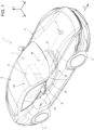
figure 1 is a schematic perspective view of an at least partially electric vehicle comprising a battery pack according to the invention; -
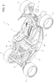
figure 2 is a schematic perspective view, with details left out for greater clarity, of an inner structure of the road vehicle offigure 1 , showing the inside of the battery pack; -
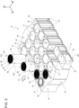
figure 3 is a schematic perspective view, with details left out for greater clarity, showing different steps of a method according to the invention for manufacturing a first embodiment of the battery pack offigure 2 ; -
figure 4 is a schematic perspective view, with details left out for greater clarity, showing different steps of a method according to the invention for manufacturing a second embodiment of the battery pack. - In
figure 1 , number 1 indicates, as a whole, a road vehicle provided with twofront wheels 2 and tworear wheels 3, at least a pair (or all) of them receiving the torque from apowertrain system 4. - The road vehicle 1 is an at least partially electric vehicle (namely, a hybrid or full electric vehicle). In other words, the
powertrain system 4 can be a hybrid system (namely, comprising an internal combustion heat engine and at least one electric motor) or an electric system (namely, solely comprising one or more electric motors). - In the figures, the same numbers and the same reference letters indicate the same elements or components with the same function.
- For the purposes of the invention, the term "second" component does not imply the presence of a "first" component. As a matter of fact, these terms are only used as labels to improve clarity and should not be interpreted in a limiting manner.
- The elements and features contained in the different preferred embodiments, drawings included, can be combined with one another, without for this reason going beyond the scope of protection of this patent application, as described hereinafter.
- The road vehicle 1 further comprises a
body 5 defining apassenger compartment 6, which is configured to accommodate at least a driver and, if necessary, one or more passengers. Thepassenger compartment 6 defines at least onecockpit 7 for the driver. - Hereinafter, expressions such as "at the top", "at the bottom", "at the front", "at the back" and others similar to them are used with reference to normal travel conditions of the vehicle 1 along the normal travel direction D.
- As shown in the non-limiting embodiment of
figure 1 , it is further possible to define: - a longitudinal axis X integral to the vehicle 1 and, in use, horizontal and parallel to a normal travel direction D of the vehicle 1;
- a transverse axis X integral to the vehicle 1 and, in use, horizontal and orthogonal to the axis X; and
- a vertical axis Z integral to the vehicle 1 and, in use, vertical and orthogonal to the axes X, Y.
- The road vehicle 1 comprises a
vehicular frame 8, which supports thebody 5. - Furthermore, the road vehicle 1 comprises a
vehicular battery pack 9 fitted to theframe 8 and preferably arranged so as to define at least part of afloorboard 10 of the road vehicle 1. - In the non-limiting embodiments of
figures 1 and2 , thevehicular battery pack 9 comprises asupport structure 11 extending along the vehicular longitudinal axis X and comprising afloor 12, which at least partly defines thefloorboard 10 of the road vehicle 1. - Advantageously, though not in a limiting manner, the
floor 12 substantially extends between a front axle (which is known and is not shown herein) and a rear axle (which is also known and is not shown herein) of the road vehicle 1. - As shown in the non-limiting embodiment of
figure 1 , thefloor 12 has a sheet-like shape (namely, it is shaped like a slab, with a thickness that is significantly smaller than the other two dimensions). - In particular, the
support structure 11 defines, on the inside, ahousing 13, which is delimited by thefloor 12 at the bottom. - Unlike prior art documents, as explained more in detail below, the
battery 9 does not consist of modules comprising a plurality of independent cells, formed and operating singularly. In particular, thebattery pack 9 does not comprise single outer containers, such as cans or pouches, which normally delimit the active materials (electrodes, separator, electrolyte) of an electrochemical cell. - The
battery pack 9 advantageously comprises a three-dimensional substrate 14, which is arranged inside thehousing 13; in particular it is supported by, hence is arranged above, thefloor 12. - The three-
dimensional substrate 14 preferably has a prismatic structure, in particular a parallelepiped-like or anyway an extruded structure, comprising a firstouter surface 15 and a secondouter surface 16 opposite the firstouter surface 15 - In particular, the first
outer surface 15 and the secondouter surface 16 are parallel to one another. - In some non-limiting cases, like the one shown in
figures 2 and3 , the firstouter surface 15 and the secondouter surface 16 are also parallel to thefloor 12. - In other non-limiting cases, like the one shown in
figure 4 , the firstouter surface 15 and the secondouter surface 16 are transverse, in particular perpendicular to thefloor 12. - Furthermore, the three-
dimensional substrate 14 is provided with a plurality ofseats 17, which extend inside thesubstrate 14 along a longitudinal axis A from anopening 18 of the first outer surface of thesubstrate 14. - The
battery pack 9 advantageously comprises a plurality of active primary units 19 (of the type used, for example, for the formation of known electrochemical cells). - In detail, the cylindrical electrochemical
primary units 19 are of the known kind, for example with lithium ions, and will not be described in detail below, for they are manufactured with known methods. - Each primary unit comprises a plurality of active materials, among which there are at least a first electrode 20 (for example, an anode or a cathode), a first separator 21 (of the known kind and not described in detail below, for example a polymer, ceramic, etc. separator), a second electrode 22 (for example, a cathode or an anode) and a second separator 23 (of the same kind as the first separator 21).
- In some non-limiting cases, the active materials are staggered relative to one another and are piled up so as to form a stack (of the kind used for assembling prismatic or pouch cells).
- In other cases, like the ones shown in the non-limiting embodiments of
figures 2 to 4 , the active materials are wound around a winding axis W so as to form a winding 24 (of the kind used for assembling cylindrical cells) . - In particular, each primary unit comprises a
first terminal 25 connected to thefirst electrode 20 and asecond terminal 26 connected to thesecond electrode 22. - As shown in the non-limiting embodiment of
figures 2 to 4 , eachprimary unit 19 is entirely inserted in arespective seat 17 of the plurality ofseats 17 of thesupport substrate 14. In particular, eachseat 17 has a shape that is complementary to the one of eachprimary unit 19. - For example, in the embodiments of
figures 3 and4 , theprimary units 17 arecylindrical windings 24; therefore, theseats 17 are cylindrical cavities, namely holes with a circular section. - In other non limiting embodiment which are nor shown herein, the
primary units 17 are stacks; therefore, theseats 17 are prismatic cavities, namely oblong slots where to insert the stacks. - Furthermore, the battery pack advantageously comprises a
first closure assembly 27, which closes the plurality ofprimary units 19 inside therespective seats 17. - According to some preferred, though non-limiting embodiments, like the one shown in
figures 3 and4 , theclosure assembly 27 comprises a plurality offirst closure elements 28, which are electrically conductive and are each arranged in the area of arespective opening 18. - The
closure elements 28 preferably are independent of one another for eachseat 17. In other words, eachseat 17 is provided with arespective closure element 28. - In particular, the
closure elements 28 aremetal caps 29, preferably with the shape of a disc, defining one of the cylindrical bases of theseat 17, in the case of thewindings 24 shown infigures 3 and4 . - In detail, the
first terminal 25 is electrically in contact with the respectivefirst closure element 28 of therespective seat 17. In this way, theclosure element 28 itself becomes thefirst terminal 25. - The
first terminal 25 is of the known kind and can be defined by a tab, a bare foil (for example, copper or aluminium) or by a plurality of tabs pressed towards the centre (also known as tabless structure). - Hence, in particular, the three-
dimensional substrate 14 defines the inner structure of thebattery pack 9, constituting the interstitial portion between theprimary units 19. - According to some non-limiting embodiments, in case a watery or anyway liquid electrolyte is used for the formation of the
battery pack 9, eachseat 17 is filled with an electrolyte before or, preferably, after theprimary unit 19 is inserted into it. In particular, the quantity of electrolyte inserted into aseat 17 is such as to completely fill theseat 17 with the respectiveprimary unit 19 inside it. - According to other non-limiting embodiments, each
primary unit 19 comprises a non-watery, gel polymer electrolyte, which permeates thefirst separator 21 and the second separator 23 (hence, for example, already part of the winding 24 between the twoelectrodes 20 and 22). - In some non-limiting cases, the
substrate 14 is made of an electrically conductive material, for example metal (steel or, preferably, aluminium). In particular, thesecond terminal 26 of each one of theprimary units 19 is electrically con contact with thesubstrate 14, thus making it a terminal 26 itself. Therefore, in these embodiments, eachfirst closure element 28 has to be electrically insulated from thesubstrate 14 because otherwise thebatter pack 9 would short-circuit. - In other preferred non-limiting cases, the
substrate 14 is made of an electrically insulating material (for example, resin). - Advantageously, though not in a limiting manner, each opening 18 is a through opening extending from the first
outer surface 15 to the secondouter surface 16 of thesubstrate 14 opposite the firstouter surface 15. - In these embodiments, the
battery pack 9 preferably comprises, furthermore, asecond closure assembly 29, which closes the plurality ofprimary units 19 inside therespective seats 17 on the side of the secondouter surface 16. In particular, thesecond closure assembly 29 comprises a plurality ofsecond closure elements 30, which are electrically conductive and are each arranged in the area of arespective seat 17. More precisely, thesecond terminal 26 is electrically in contact with the respectivesecond closure element 30 of therespective seat 17. - Preferably, though not in a limiting manner, the
second closure elements 30 are of the same kind as thefirst closure elements 28. - According to some preferred, though non-limiting embodiments, the
support substrate 14 is manufactured by means of additive manufacturing techniques, such as for example stereolithography, fused deposition modelling or selective laser sintering (used selectively depending on the material used for the substrate 14) . In this way, the customization of the shape of thebattery pack 9 is improved for each model of road vehicle 1. Furthermore, additive manufacturing allows for the creation of asubstrate 14 provided with an net-like interstitial section, between one seat and the other, thus lightening the battery pack and improving the elasticity thereof at the same time. - According to other non-limiting embodiments, the support substrate is manufactured by means of traditional subtractive manufacturing methods (by means of presses, milling machines or lathes) with casting of molten material into suitable dies.
- In some non-limiting cases, which are not shown herein, the seat has such a length, along the longitudinal axis A, that it can accommodate more the one
primary unit 19. For example, in case ofwindings 24, the seat has such a length, along the longitudinal axis A, thatseveral windings 24 can be placed (in series) inside asame seat 17. - According to some preferred, though non-limiting embodiments, like the ones shown in
figures 3 and4 , thesubstrate 14 has a prismatic shape, namely a shape having two opposite bases spaced apart from one another by the volume of thesubstrate 14 itself. In particular, at least a lower base of thesubstrate 14, namely the one in contact with thefloor 12, has a shape such as to fill thefloor 12 of thebattery pack 9 as much as possible. - In particular, as shown in the non-limiting embodiments of the accompanying drawings, the assembly made up of the
substrate 14, the first closure assembly 27 (if necessary, the second closure assembly 29) and theprimary units 19 defines alayer 31 of cells. - Hence, in particular, unlike the prior art, the
battery pack 9 does not comprise singularly movable electrochemical cells, but the three-dimensional substrate 14 supports theprimary units 19 and theclosure assemblies primary units 19 can be brought closer to one another, since they are normally separated by a double thickness due to the cans or the pouches that singularly surround them. On the contrary, thebattery pack 9 has one single separating layer between adjacentprimary units 19, thus optimizing the spaces available inside thebattery pack 9, which can accommodate a larger number ofprimary units 19 in the same volume. - According to some non-limiting cases, like the one shown in
figure 1 , thebattery pack 9 comprises a plurality oflayers 31 of cells on top of one another (for example, in the case of the embodiment offigure 3 ) or next to one another (for example, in the case of the embodiment offigure 4 ). - Advantageously, though not in a limiting manner, and as shown in the embodiments of
figures 2 to 4 , in order to optimize spaces, theseats 17 are arranged along parallel longitudinal axes A. - In particular, in the non-limiting embodiment of
figure 3 , the parallel longitudinal axes A are, in turn, perpendicular to the floor 12 (whether it is perfectly parallel to the ground or slightly inclined). More in particular, the parallel longitudinal axes A are parallel to the vertical axis Z (or at most at a 10° angle, preferably at most at a 5° angle relative to the latter). - In particular, in the non-limiting embodiment of
figure 4 , the parallel longitudinal axes A are, in turn, parallel to the floor 12 (whether it is perfectly parallel to the ground or slightly inclined). More in particular, the parallel longitudinal axes A are parallel to the transverse axis Y. - Advantageously, though not in a limiting manner, the
battery pack 9 further comprisesrefrigeration channels 32 parallel to the longitudinal axes A of theseats 17 and interposed between theseats 17. Hence, in other words, therefrigeration channels 32 are obtained in thesubstrate 14, in particular in the separation zone between theprimary units 19. In this way, the cooling of the active parts of the battery pack is improved 9, since the casings of the single cells no longer need to be cooled. - In particular, the
primary units 19 of the battery pack are electrically connected to one another through the interconnection of theclosure elements 28, 30 (if present) and, if necessary, of thesubstrate 14, if it is electrically conductive. - In the non-limiting embodiment of
figure 4 , the horizontal arrangement of theprimary units 19 allows the three-dimensional substrate 14 to also adjust to a curved shape of thefloor 12 of thebattery pack 9. - In the non-limiting embodiment of
figure 1 , thefloor 12 comprises, along the longitudinal axis X, afront portion 33 substantially parallel to the ground G and arear portion 34 diverging from the ground G. - According to some preferred, though non-limiting embodiments, like the one shown in the accompanying drawings, the primary units of a
same layer 31 of cells are arranged so as to form a quincux formation. In other words, theseats 17 are staggered so as to maximize the quantity ofprimary units 19 in the same volume. - Preferably, as shown in the non-limiting embodiment of
figure 3 , thebattery pack 9 comprises averticalized portion 35 supported by therear portion 34 and having a greater thickness than the rest of thebattery pack 9. In particular, theverticalized portion 35 comprises at least two, in particular at least threelayers 31 of cells on top of one another (or next to one another, in case a configuration according to the embodiment offigure 4 is used). - Advantageously, though not necessarily, the
battery pack 9 further comprises a loweredportion 36 supported by thefront portion 33 and having a smaller thickness than theverticalized portion 35. - In particular, in the lowered
portion 36 there is only one layer ofcells 31, preferably with theprimary units 19 arranged with the longitudinal axis A horizontal. - Advantageously, though not in a limiting manner, the
battery pack 9 is arranged at the bottom of thepassenger compartment 6. In particular, thefront portion 33 is arranged under thecockpit 7 and the possible passenger's seat beside it, whereas therear portion 34 is arranged behind the seats contained inside thepassenger compartment 6. - In particular, the
battery pack 9 is suited to be connected to thepowertrain system 4 of the at least partially electric vehicle 1 and is designed to store the power produced by an electric machine (which is not shown herein). Thebattery pack 9 is connected to the electric machine through the interposition of a power converter (commonly known as inverter), which, based on the different needs of the electric machine and of thebattery pack 9, transforms the direct current outputted by thebattery pack 9 into alternating current for the electric machine and vice versa. - The
battery pack 9 comprises at least one section configured to house a battery management system - BMS designed to control the operating parameters of theprimary units 19 by measuring a plurality of parameters relating to thefirst terminal 25 and/or to thesecond terminal 26, which are connected to general terminals of thebattery pack 9 with a known BUS connection. - According to a further aspect of the invention, there is provided a method for assembling a
vehicular battery pack 9. - The method comprises the steps of providing, for example conveying along a production line, the
support structure 11 and of placing thesubstrate 14 inside the housing. - The method further comprises the step of providing, hence conveying, for example to a store, a plurality of active primary units 19 (for example
cylindrical windings 14 or planar stacks). - In addition, the method comprises the step of entirely inserting, preferably by means of a robotic manipulator, each
primary unit 19 into arespective seat 17. In particular, the insertion has to be carried out with precision in order not to damage theprimary units 19, since eachseat 17 has a shape that is complementary to the one of eachprimary unit 19. - Furthermore, the method advantageously comprises the step of closing said plurality of
seats 17, each accommodating, on the inside, at least one respectiveprimary unit 19, by means at least of the first closure assembly 27 (or, if necessary, in combination with the second closure assembly 29), which closes said plurality ofprimary units 19 inside therespective seats 17. In particular, the method comprise closing thefirst closure elements 28 and, if necessary, thesecond closure elements 30 one by one or in groups. - In particular the method further comprises the step of placing, prior to or concurrently with the closing step, the
first terminal 25 electrically in contact with the respectivefirst closure element 28 of therespective seat 17. - Advantageously, though not in a limiting manner, in case there is the
second closure assembly 29, it is placed on thesubstrate 14 so as to close/seal theseats 17 on the side of thesecond surface 16. In particular, this step takes place before theseats 17 are filled with theprimary units 19. - According to some preferred non-limiting embodiments, the method comprises the prior step of manufacturing the
substrate 14 by means of additive manufacturing techniques of the kind described above or by means of casting into dies or subtractive manufacturing. - In particular, in case the
primary units 19 are not of the so-called solid state (SS) kind, the method comprises the step of filling, before or preferably after the insertion of theprimary units 19 into therespective seats 17, said plurality ofseats 17 with an electrolyte. More in particular, the introduced quantity of electrolyte is sufficient to drown the plurality ofprimary units 19 and eliminate air from within theseats 19 before the step of closing with thefirst closure assembly 27. - Preferably, though not in a limiting manner, the method comprises the further step of placing
several layers 31 of cells, on top of or next to one another, on thefloor 12 of thebattery pack 9. - Advantageously, though not in a limiting manner, during the further placing step, the
verticalized portion 35 is formed, which is supported by therear portion 34 and has a greater thickness than the rest of thebattery pack 9. In particular, in theverticalized portion 35 there are at least two, in particular at least threelayers 31 on top of one another (in particular, horizontal layers). - Finally, not in a limiting manner, the method comprises the step of forming the
battery pack 9 carrying out charging/discharging cycles, which merge those that are normally carried out for the single electrochemical cells making up prior art battery packs. - Even though the invention described above specifically relates to some precise embodiments, it should not be considered as limited to said embodiments, for its scope of protection also includes all those variants, changes or simplifications covered by the appended claims, such as for example a different shape of the battery pack, a different location thereof, a different type of materials, etc.
- The invention offers many advantages.
- First of all, it eliminates the metal containers of the single electrochemical cells, which determine an undesired increase in weight and dimensions.
- Furthermore, as a consequence of said improved use of the space, more primary unit can be inserted in the same volume.
- A further advantage of the invention lies in the possibility of customizing each battery pack so as to fill as much volume as possible in the vehicular floorboard, thus generating not necessarily rectangular shapes.
- Furthermore, the use of additive techniques improves the elasticity and increases the lightness of the battery pack.
- In addition, there are a plurality of refrigeration channels, which are directly integrated in the substrate and ensure an optimized cooling efficiency.
- Finally, thanks to the invention, the geometric limits to which state-of-the-art battery packs are currently subjected can be overcome, thus freeing designers from the idea of a battery pack consisting of single units that have to be coupled to maximize the capacity thereof.
-
- 1
- vehicle
- 2
- wheels
- 3
- wheels
- 4
- powertrain system
- 5
- body
- 6
- passenger compartment
- 7
- cockpit
- 8
- frame
- 9
- battery pack
- 10
- floorboard
- 11
- support structure
- 12
- floor
- 13
- housing
- 14
- substrate
- 15
- first outer surface
- 16
- second outer surface
- 17
- seats
- 18
- opening
- 19
- primary units
- 20
- first electrode
- 21
- first separator
- 22
- second electrode
- 23
- second separator
- 24
- winding
- 25
- first terminal
- 26
- second terminal
- 27
- first closure assembly
- 28
- first closure elements
- 29
- second closure assembly
- 30
- second closure elements
- 31
- layer of cells
- 32
- refrigeration channels
- 33
- front portion
- 34
- rear portion
- 35
- verticalized portion
- 36
- lowered portion
- A
- longitudinal axis
- D
- direction
- G
- ground
- W
- winding axis
- X
- axis
- Y
- axis
- Z
- axis
Claims (15)
- A vehicular battery pack (9) comprising:- a support structure (11) extending along a vehicular axis (X), defining within it a housing (13);- a three-dimensional substrate (14) disposed within the housing (13) and provided with a plurality of seats (17), each extending internally to the substrate (14) along an axis (A) longitudinally from an opening (18) of a first surface (15) external to the substrate (14);- a plurality of active primary units (19); each primary unit (19) comprising at least a first electrode (20), a first separator (21), a second electrode (22) and a second separator (23), arranged alternated each other and stacked together to form a stack or wound to form a winding (24); each primary unit (19) comprising a first terminal (25) connected to the first electrode (20) and a second terminal (26) connected to the second electrode (22);wherein each primary unit (19) is entirely inserted into a respective seat (17) of the plurality of seats (17) of the substrate (14); wherein each seat (17) has a shape complementary to that of each primary unit (19);
the battery pack (9) further comprising a first closure assembly (27), which closes a plurality of primary units (19) inside the respective seats (17); wherein the closure assembly comprises a plurality of first closure elements (28) each electrically conductive and arranged at a respective opening (18);
wherein the first terminal (25) is electrically in contact with the respective first closure element of the respective housing (17). - The battery pack (9) according to claim 1, wherein each primary unit (19) is immersed in an electrolyte in the respective seat (17).
- The battery pack (9) according to claim 1, wherein each primary unit (19) comprises a non-aqueous polymeric gel electrolyte, which permeates the first separator (21) and the second separator (23).
- The battery pack (9) according to any one of claims 1 to 3, wherein the substrate (14) is made of an electrically conductive material; wherein the second terminal (26) is electrically in contact with the substrate (14) making it itself the second terminal (26); wherein each first closure element is electrically insulated from the substrate (14).
- The battery pack (9) according to any one of claims 1 to 3, wherein the substrate (14) is made of an electrically insulating material;wherein each opening (18) is a through opening (18) extending from the first outer surface (15) to a second outer surface (16) of the substrate (14) opposite the first outer surface (15);wherein the battery pack (9) further comprises a second closure assembly (30), which encloses the plurality of primary units (19) within respective housings (17) on the side of the second outer surface (16); wherein the second closure assembly (30) comprises a plurality of second electrically conductive closure elements (30) each disposed at a respective housing (17);wherein the second terminal (26) is electrically in contact with the respective second closure element of the respective seat (17).
- The battery pack (9) according to any one of the preceding claims, wherein the substrate (14) is made by additive manufacturing techniques.
- The battery pack (9) according to any one of the preceding claims, wherein multiple windings may be arranged in series within a single seat (17).
- The battery pack (9) according to any one of the preceding claims, wherein the substrate (14) has a prismatic shape; wherein the assembly comprising the substrate (14) with the first closure assembly (27) and the primary units (19) defines a layer (31) of cells.
- The battery pack (9) according to claim 8 and comprising a plurality of overlapping or side-by-side layers (31) of cells.
- The battery pack (9) according to any one of the preceding claims, wherein the seats (17) are arranged along parallel longitudinal axes, the battery pack (9) further comprising refrigeration channels (32) parallel to the longitudinal axes of the seats (17) and interposed between the seats (17) themselves.
- Electric or hybrid road vehicle (1) comprising:- four wheels (2, 3), of which at least one pair of wheels (2, 3) is driven;- a passenger compartment (6);- a power train system (4) configured to control the motion of the driving wheels (2, 3);- a battery pack (9) according to any one of claims 1 to 10.
- The road vehicle (1) according to claim 11, wherein the battery pack (9) is mounted to a frame (8) of the road vehicle (1) and is arranged to define at least part of a floor pan (10) of the road vehicle (1).
- Method of assembling a vehicle battery pack (9) comprising the steps of:- providing a substrate (14) with a plurality of seats (17), each extending along a longitudinal axis (A) from an opening (18) of a first surface (15) on the outside of the substrate (14) towards the inside of the substrate (14) itself;- providing a plurality of active primary units (19); each primary unit (19) comprising at least a first electrode (20), a first separator (21), a second electrode (22) and a second separator (23), arranged alternated each other and stacked together to form a stack or coiled to form a coil (24); each primary unit (19) comprising a first terminal (25) connected to the first electrode (20) and a second terminal (26) connected to the second electrode (22);- inserting each primary unit (19) entirely within a respective seat (17) of the plurality of seats (17) of the substrate (14); wherein each seat (17) has a shape complementary to that of each primary unit (19);- closing the plurality of seats (17) with within, each, at least one respective primary unit (19) by means of at least one first closure assembly (27), which comprises the plurality of primary units (19) within the respective seat (17); wherein the closure assembly comprises a plurality of electrically conductive first closure elements (28) each arranged at a respective seat (17);- arranging, prior to or concurrently with the step of closing, the first terminal (25) electrically in contact with the respective first closure element of the respective seat (17).
- The method according to claim 13 and comprising the further step of making the substrate (14) by means of additive manufacturing techniques, printing or casting.
- The method according to claim 13 or 14 and comprising the step of filling, before or after inserting the primary units (19) into the respective seat (17), the plurality of seats (17) with electrolyte; wherein the amount of electrolyte injected is sufficient to drown the plurality of primary units (19) and eliminate air from within the housings (17).
Applications Claiming Priority (1)
| Application Number | Priority Date | Filing Date | Title |
|---|---|---|---|
| IT202300005292 | 2023-03-21 |
Publications (1)
| Publication Number | Publication Date |
|---|---|
| EP4435919A1 true EP4435919A1 (en) | 2024-09-25 |
Family
ID=86657056
Family Applications (1)
| Application Number | Title | Priority Date | Filing Date |
|---|---|---|---|
| EP24164374.1A Pending EP4435919A1 (en) | 2023-03-21 | 2024-03-19 | Vehicular battery pack and related assembly method |
Country Status (3)
| Country | Link |
|---|---|
| US (1) | US20240322305A1 (en) |
| EP (1) | EP4435919A1 (en) |
| CN (1) | CN222071987U (en) |
Citations (6)
| Publication number | Priority date | Publication date | Assignee | Title |
|---|---|---|---|---|
| US6255015B1 (en) * | 1998-08-23 | 2001-07-03 | Ovonic Battery Company, Inc. | Monoblock battery assembly |
| US7547487B1 (en) * | 2004-05-18 | 2009-06-16 | Ovonic Battery Company, Inc. | Multi-cell battery assembly |
| US20100143773A1 (en) * | 2008-12-04 | 2010-06-10 | Hitachi Vehicle Energy, Ltd. | Lithium secondary battery, secondary battery module, and secondary battery pack |
| US20150280185A1 (en) | 2012-10-11 | 2015-10-01 | Clotearn, LLC | Lithium Ion Battery |
| US20180069280A1 (en) * | 2016-09-07 | 2018-03-08 | Thunder Power New Energy Vehicle Development Company Limited | Battery system assembly process and battery system assembly |
| DE102021122486A1 (en) * | 2021-08-31 | 2023-03-02 | Bayerische Motoren Werke Aktiengesellschaft | Housing for electrode stack and battery cell group |
Family Cites Families (17)
| Publication number | Priority date | Publication date | Assignee | Title |
|---|---|---|---|---|
| US4346151A (en) * | 1980-12-29 | 1982-08-24 | The Gates Rubber Company | Multicell sealed rechargeable battery |
| US6051336A (en) * | 1998-01-19 | 2000-04-18 | Johnson Controls Technology | Battery case for thin metal film cells |
| CN101627490B (en) * | 2006-12-14 | 2012-10-03 | 江森自控帅福得先进能源动力系统有限责任公司 | Battery module |
| US8049460B2 (en) * | 2007-07-18 | 2011-11-01 | Tesla Motors, Inc. | Voltage dividing vehicle heater system and method |
| KR101393167B1 (en) * | 2009-05-20 | 2014-05-08 | 존슨 컨트롤즈 테크놀로지, 엘엘씨 | Lithium ion battery module |
| KR101093695B1 (en) * | 2009-10-16 | 2011-12-19 | 삼성에스디아이 주식회사 | Battery module |
| EP2522047A1 (en) * | 2010-01-08 | 2012-11-14 | Dow Global Technologies LLC | Thermal management of an electrochemical cell by a combination of heat transfer fluid and phase change material |
| EP2521202B1 (en) * | 2010-02-03 | 2016-06-08 | Panasonic Intellectual Property Management Co., Ltd. | Power source |
| WO2012124273A1 (en) * | 2011-03-17 | 2012-09-20 | パナソニック株式会社 | Battery block |
| KR101265199B1 (en) * | 2011-08-08 | 2013-05-23 | 삼성에스디아이 주식회사 | Rechargeable battery |
| US8920955B1 (en) * | 2012-12-13 | 2014-12-30 | Atieva, Inc. | Battery module with high thermal conductivity and assembling method thereof |
| US20150221904A1 (en) * | 2014-02-04 | 2015-08-06 | General Electric Company | Battery modules and cells with insulated module block, and method for manufacturing |
| ES2778903T3 (en) * | 2014-02-14 | 2020-08-12 | Intramicron Inc | Thermal management systems for energy storage cells that have high charge / discharge currents and procedures for their manufacture and use |
| EP4391171A4 (en) * | 2022-01-14 | 2025-07-23 | Contemporary Amperex Technology Hong Kong Ltd | BATTERY PACK AND ELECTRICAL DEVICE |
| DE102022133622A1 (en) * | 2022-12-16 | 2024-06-27 | Elringklinger Ag | Form element, energy storage device, structural component and method for producing a form element |
| CN118825575A (en) * | 2023-04-18 | 2024-10-22 | 宁德时代新能源科技股份有限公司 | Battery cells, batteries and electrical devices |
| CN118198665A (en) * | 2023-04-28 | 2024-06-14 | 宁德时代新能源科技股份有限公司 | Battery cells, batteries and electrical devices |
-
2024
- 2024-03-19 US US18/609,146 patent/US20240322305A1/en active Pending
- 2024-03-19 EP EP24164374.1A patent/EP4435919A1/en active Pending
- 2024-03-21 CN CN202420559485.7U patent/CN222071987U/en active Active
Patent Citations (6)
| Publication number | Priority date | Publication date | Assignee | Title |
|---|---|---|---|---|
| US6255015B1 (en) * | 1998-08-23 | 2001-07-03 | Ovonic Battery Company, Inc. | Monoblock battery assembly |
| US7547487B1 (en) * | 2004-05-18 | 2009-06-16 | Ovonic Battery Company, Inc. | Multi-cell battery assembly |
| US20100143773A1 (en) * | 2008-12-04 | 2010-06-10 | Hitachi Vehicle Energy, Ltd. | Lithium secondary battery, secondary battery module, and secondary battery pack |
| US20150280185A1 (en) | 2012-10-11 | 2015-10-01 | Clotearn, LLC | Lithium Ion Battery |
| US20180069280A1 (en) * | 2016-09-07 | 2018-03-08 | Thunder Power New Energy Vehicle Development Company Limited | Battery system assembly process and battery system assembly |
| DE102021122486A1 (en) * | 2021-08-31 | 2023-03-02 | Bayerische Motoren Werke Aktiengesellschaft | Housing for electrode stack and battery cell group |
Also Published As
| Publication number | Publication date |
|---|---|
| CN222071987U (en) | 2024-11-26 |
| US20240322305A1 (en) | 2024-09-26 |
Similar Documents
| Publication | Publication Date | Title |
|---|---|---|
| US20220285768A1 (en) | Prismatic battery cell energy density for a lithium ion battery module | |
| US10862159B2 (en) | Free floating battery cell assembly techniques for lithium ion battery module | |
| US20220285799A1 (en) | Prismatic lithium ion cell with positive polarity rigid container | |
| EP3446346B1 (en) | Multicavity battery module | |
| EP3198661B1 (en) | Lithium ion battery module with floating prismatic battery cells | |
| JP6844458B2 (en) | Batteries | |
| US20230395947A1 (en) | Battery systems, methods, and vehicles with interconnect board assemblies having multilayer current collectors | |
| CN106252546B (en) | Battery cell separator for establishing a dielectric barrier in a battery assembly | |
| US10680297B2 (en) | Tab cooling for pouch cell | |
| US20250192353A1 (en) | Venting thermal exchange device for battery pack | |
| US20240063499A1 (en) | Battery container vents with pressure burst covers using electrical interlocks for detecting thermal events | |
| EP4434787B1 (en) | Vehicular battery pack and related assembly method | |
| EP4435919A1 (en) | Vehicular battery pack and related assembly method | |
| US10668826B1 (en) | Electric vehicle lithium batteries having non-uniform anode layer | |
| US20240194963A1 (en) | Battery cell assemblies, thermal management systems, and control logic with cell-level internal cooling | |
| US12255347B1 (en) | Configurable battery pack | |
| US20250183412A1 (en) | Systems and methods for mitigating thermal propagation within traction battery arrays | |
| CN120545591A (en) | Inverted battery assembly | |
| EP2774190B1 (en) | Prismatic lithium ion cell with positive polarity rigid container | |
| CN120978348A (en) | Current collector assembly with bent interconnect sections | |
| CN118676512A (en) | Traction battery pack cell block assembly excluding cell-to-cell spacers | |
| CN118281471A (en) | Bracket for battery cell |
Legal Events
| Date | Code | Title | Description |
|---|---|---|---|
| PUAI | Public reference made under article 153(3) epc to a published international application that has entered the european phase |
Free format text: ORIGINAL CODE: 0009012 |
|
| STAA | Information on the status of an ep patent application or granted ep patent |
Free format text: STATUS: THE APPLICATION HAS BEEN PUBLISHED |
|
| AK | Designated contracting states |
Kind code of ref document: A1 Designated state(s): AL AT BE BG CH CY CZ DE DK EE ES FI FR GB GR HR HU IE IS IT LI LT LU LV MC ME MK MT NL NO PL PT RO RS SE SI SK SM TR |
|
| STAA | Information on the status of an ep patent application or granted ep patent |
Free format text: STATUS: REQUEST FOR EXAMINATION WAS MADE |
|
| 17P | Request for examination filed |
Effective date: 20250325 |