EP4435549B1 - Robotic navigation with simultaneous local path planning and learning - Google Patents
Robotic navigation with simultaneous local path planning and learning Download PDFInfo
- Publication number
- EP4435549B1 EP4435549B1 EP24152871.0A EP24152871A EP4435549B1 EP 4435549 B1 EP4435549 B1 EP 4435549B1 EP 24152871 A EP24152871 A EP 24152871A EP 4435549 B1 EP4435549 B1 EP 4435549B1
- Authority
- EP
- European Patent Office
- Prior art keywords
- approach
- value
- robotic agent
- current
- nbq
- Prior art date
- Legal status (The legal status is an assumption and is not a legal conclusion. Google has not performed a legal analysis and makes no representation as to the accuracy of the status listed.)
- Active
Links
Images


Classifications
-
- G—PHYSICS
- G05—CONTROLLING; REGULATING
- G05D—SYSTEMS FOR CONTROLLING OR REGULATING NON-ELECTRIC VARIABLES
- G05D1/00—Control of position, course, altitude or attitude of land, water, air or space vehicles, e.g. using automatic pilots
- G05D1/60—Intended control result
- G05D1/644—Optimisation of travel parameters, e.g. of energy consumption, journey time or distance
-
- G—PHYSICS
- G05—CONTROLLING; REGULATING
- G05D—SYSTEMS FOR CONTROLLING OR REGULATING NON-ELECTRIC VARIABLES
- G05D1/00—Control of position, course, altitude or attitude of land, water, air or space vehicles, e.g. using automatic pilots
- G05D1/20—Control system inputs
- G05D1/22—Command input arrangements
- G05D1/229—Command input data, e.g. waypoints
-
- G—PHYSICS
- G01—MEASURING; TESTING
- G01C—MEASURING DISTANCES, LEVELS OR BEARINGS; SURVEYING; NAVIGATION; GYROSCOPIC INSTRUMENTS; PHOTOGRAMMETRY OR VIDEOGRAMMETRY
- G01C21/00—Navigation; Navigational instruments not provided for in groups G01C1/00 - G01C19/00
- G01C21/20—Instruments for performing navigational calculations
- G01C21/206—Instruments for performing navigational calculations specially adapted for indoor navigation
-
- G—PHYSICS
- G05—CONTROLLING; REGULATING
- G05D—SYSTEMS FOR CONTROLLING OR REGULATING NON-ELECTRIC VARIABLES
- G05D1/00—Control of position, course, altitude or attitude of land, water, air or space vehicles, e.g. using automatic pilots
- G05D1/20—Control system inputs
- G05D1/24—Arrangements for determining position or orientation
- G05D1/242—Means based on the reflection of waves generated by the vehicle
-
- G—PHYSICS
- G05—CONTROLLING; REGULATING
- G05D—SYSTEMS FOR CONTROLLING OR REGULATING NON-ELECTRIC VARIABLES
- G05D1/00—Control of position, course, altitude or attitude of land, water, air or space vehicles, e.g. using automatic pilots
- G05D1/20—Control system inputs
- G05D1/24—Arrangements for determining position or orientation
- G05D1/246—Arrangements for determining position or orientation using environment maps, e.g. simultaneous localisation and mapping [SLAM]
- G05D1/2469—Arrangements for determining position or orientation using environment maps, e.g. simultaneous localisation and mapping [SLAM] using a topologic or simplified map
-
- G—PHYSICS
- G05—CONTROLLING; REGULATING
- G05D—SYSTEMS FOR CONTROLLING OR REGULATING NON-ELECTRIC VARIABLES
- G05D1/00—Control of position, course, altitude or attitude of land, water, air or space vehicles, e.g. using automatic pilots
- G05D1/60—Intended control result
- G05D1/65—Following a desired speed profile
-
- G—PHYSICS
- G05—CONTROLLING; REGULATING
- G05D—SYSTEMS FOR CONTROLLING OR REGULATING NON-ELECTRIC VARIABLES
- G05D2101/00—Details of software or hardware architectures used for the control of position
- G05D2101/10—Details of software or hardware architectures used for the control of position using artificial intelligence [AI] techniques
- G05D2101/15—Details of software or hardware architectures used for the control of position using artificial intelligence [AI] techniques using machine learning, e.g. neural networks
-
- G—PHYSICS
- G05—CONTROLLING; REGULATING
- G05D—SYSTEMS FOR CONTROLLING OR REGULATING NON-ELECTRIC VARIABLES
- G05D2107/00—Specific environments of the controlled vehicles
- G05D2107/70—Industrial sites, e.g. warehouses or factories
-
- G—PHYSICS
- G05—CONTROLLING; REGULATING
- G05D—SYSTEMS FOR CONTROLLING OR REGULATING NON-ELECTRIC VARIABLES
- G05D2109/00—Types of controlled vehicles
- G05D2109/10—Land vehicles
Definitions
- the embodiments herein generally relate to the field of robot navigation and, more particularly, to a method and system for robotic navigation with simultaneous local path planning and learning.
- Online planning or offline learning based planning is the key for any successful navigation from a given position to another in a robotic environment. Online planning suffers from repeated planning for minor positional modifications. Learning circumvents this repeated planning by learning the action (e.g., velocity vector) for the minor positional modifications. Unfortunately, the learning algorithms either works in offline or requires a priori training data. Thus, in conventional robot navigation techniques learning and planning algorithms act independently without guiding each other simultaneously.
- Document CN114564016A discloses a navigation obstacle avoidance control method, a navigation obstacle avoidance control system and a navigation obstacle avoidance control model combining path planning and reinforcement learning, wherein a driving task is divided into static path planning and dynamic optimal track tracking, the combination of a rule-based path planning algorithm and deep reinforcement learning is realized, and the problem of difficult vehicle control under a complex road scene (such as left turn at a signal lamp-free intersection) can be effectively solved.
- the method does not need to adjust the parameters manually and continuously.
- the method does not depend on the model precision of the controlled object excessively, meanwhile, the complexity of the solving process is greatly reduced, and the vehicle-mounted real-time computing efficiency is improved.
- the method Compared with end-to-end reinforcement learning, the method combines the kinematics model of the vehicle, has interpretability, and greatly improves the safety of the vehicle in the navigation process (Abstract).
- Document Ketan Doshi in " Reinforcement Learning Explained Visually (Part 3): Model-free solutions, step-by-step
- this article discloses about n about the core techniques used by all solutions. Using an iterative algorithm as a framework to incrementally improve predictions, this article understands the fundamental similarities and differences between Value-based and Policy-based solutions.
- the invention is as defined in method claim 1.
- the invention is as defined in a system claim 3.
- Path planning for a mobile robot is the process of finding a sequence of valid collision-free configurations to transport the mobile robot from one position to another.
- Global path planning algorithm offers path between start and goal on a given world in offline.
- environmental uncertainties e.g., amendment of stationary object/obstacle in the world
- global planner requires frequent replanning.
- global planners are computationally expensive.
- a local planner works on local environment, which is created locally within sensing range, and does not include any global information. Hence, the robot may be stuck in local minima as shown by state-of-the art.
- the computational cost of the local path planning algorithm is less as compared to the global path planning algorithm.
- the local path planning algorithms in the art are capable enough to deal with frequent changes in the surroundings.
- One of the initial local path planning approaches is introduced as a curvature velocity method.
- the basics of the curvature velocity method is maximizing an objective function by choosing one suitable velocity sample (satisfying necessary constraints) from a velocity space.
- the concept of dynamic window approach (DWA) is derived by another existing work.
- the dynamic window is defined on the basis of the kinematics model and current velocity of the robot.
- a score is computed by selecting each velocity sample from the dynamic window as a function of robot's goal heading, velocity, and distance from the nearest obstacle. The velocity sample with maximum score value is selected for execution.
- Improvement of DWA is done by another existing method for better navigation capabilities in partially unknown environments among obstacles. Some works further proposed a Global DWA in order to avoid trapping in local minima. Besides several improvements of DWA, following technical limitations of DWA are specified in the literature. Firstly, the evaluation functions are not sufficient to identify potential velocity sample in the dynamic window. Hence, potential velocity sample may be ignored. Secondly, the score function is weighted sum of evaluation functions, and performance of the DWA highly depends on the choice of weight values. Former hindrances are circumvented by employing reinforcement learning and by deep reinforcement learning in the recent works in the art. However, these recent approaches require offline learning or training with a priori training data. Additionally, dimension of Q-table is defined a priori in the works in literature.
- simultaneous learning and planning algorithm (SLPA) is proposed in the art.
- the SLPA works for a fixed start and goal pair and needs to reinitialize if start and/or goal are/is altered.
- start and local goal keep on changing. So, local planning by employing SLPA is not feasible.
- Embodiments herein disclose a method and system for robotic navigation with simultaneous local path planning and learning by a robotic agent.
- the method discloses an approach that enables the robotic agent, also referred as mobile robot or robot interchangeably, to learn and plan simultaneously, based on SLPA in sensing range (SLPA-SR) approach, a wherein learning and planning techniques are synergistically combined to assist each other and improve the overall navigational performance of the robot.
- the planner acts as an actuator and helps to balance exploration and exploitation in the learning algorithm.
- DWA dynamic window approach
- NBQ Next best Q-learning
- dimension of Q-tree in the NBQ is dynamic and does not require to define a priori.
- FIGS. 1A through 9 where similar reference characters denote corresponding features consistently throughout the figures, there are shown preferred embodiments and these embodiments are described in the context of the following exemplary system and/or method.
- FIG. 1A is a functional block diagram of a system 100, interchangeably referred to as a robotic agent 100, for robotic navigation with simultaneous local path planning and learning, in accordance with some embodiments of the present disclosure.
- the system 100 includes a processor(s) 104, communication interface device(s), alternatively referred as input/output (I/O) interface(s) 106, and one or more data storage devices or a memory 102 operatively coupled to the processor(s) 104.
- the system 100 with one or more hardware processors is configured to execute functions of one or more functional blocks of the system 100.
- the robotic agent is integrated with a sensor, for example a light detection and ranging LiDAR, (not shown) to sense the environment of the robot during navigation towards a goal position.
- a sensor for example a light detection and ranging LiDAR, (not shown) to sense the environment of the robot during navigation towards a goal position.
- the processor(s) 104 can be one or more hardware processors 104.
- the one or more hardware processors 104 can be implemented as one or more microprocessors, microcomputers, microcontrollers, digital signal processors, central processing units, state machines, logic circuitries, and/or any devices that manipulate signals based on operational instructions.
- the one or more hardware processors 104 are configured to fetch and execute computer-readable instructions stored in the memory 102.
- the system 100 can be implemented in a variety of computing systems including laptop computers, notebooks, hand-held devices such as mobile phones, workstations, mainframe computers, servers, and the like.
- the I/O interface(s) 106 can include a variety of software and hardware interfaces, for example, a web interface, a graphical user interface, and the like and can facilitate multiple communications within a wide variety of networks N/W and protocol types, including wired networks, for example, LAN, cable, etc., and wireless networks, such as WLAN, cellular and the like.
- the I/O interface (s) 106 can include one or more ports for connecting to a number of external devices or to another server or devices.
- the memory 102 may include any computer-readable medium known in the art including, for example, volatile memory, such as static random access memory (SRAM) and dynamic random access memory (DRAM), and/or non-volatile memory, such as read only memory (ROM), erasable programmable ROM, flash memories, hard disks, optical disks, and magnetic tapes.
- volatile memory such as static random access memory (SRAM) and dynamic random access memory (DRAM)
- DRAM dynamic random access memory
- non-volatile memory such as read only memory (ROM), erasable programmable ROM, flash memories, hard disks, optical disks, and magnetic tapes.
- the memory 102 includes a plurality of modules 110.
- the plurality of modules 110 include programs or coded instructions that supplement applications or functions performed by the system 100 for executing different steps involved in the process of robotic navigation with simultaneous local path planning and learning, being performed by the system 100.
- the plurality of modules 110 can include routines, programs, objects, components, and data structures, which performs particular tasks or implement particular abstract data types.
- the plurality of modules 110 may also be used as, signal processor(s), node machine(s), logic circuitries, and/or any other device or component that manipulates signals based on operational instructions. Further, the plurality of modules 110 can be used by hardware, by computer-readable instructions executed by the one or more hardware processors 104, or by a combination thereof.
- the plurality of modules 110 can include various sub-modules (not shown) such as modules executing the DWA and the NBQ as depicted in FIG. 1B .
- the memory 102 may comprise information pertaining to input(s)/output(s) of each step performed by the processor(s) 104 of the system100 and methods of the present disclosure.
- the memory 102 includes a database 108.
- the database (or repository) 108 may include a plurality of abstracted piece of code for refinement and data that is processed, received, or generated as a result of the execution of the plurality of modules in the module(s) 110, for example, a 2D floor plan, a goal position, a plurality of way points to reach the goal positions, the Q-tree, the local goals, a plurality of states visited by the robotic agent and so on.
- the data base 108 is shown internal to the system 100, it will be noted that, in alternate embodiments, the database 108 can also be implemented external to the system 100, and communicatively coupled to the system 100. The data contained within such external database may be periodically updated. For example, new data may be added into the database (not shown in FIG.
- LDAP Lightweight Directory Access Protocol
- RDBMS Relational Database Management System
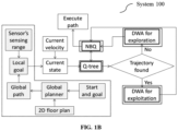
- FIG. 1B illustrates high level process flow of the system 100 of FIG. 1A , in accordance with some embodiments of the present disclosure.
- FIGS. 2A through 2B (collectively referred as FIG. 2 ) is a flow diagram illustrating a method 200 for robotic navigation with simultaneous local path planning and learning, using the system depicted in FIG. 1A and FIG. 1B , in accordance with some embodiments of the present disclosure.
- the system 100 comprises one or more data storage devices or the memory 102 operatively coupled to the processor(s) 104 and is configured to store instructions for execution of steps of the method 200 by the processor(s) or one or more hardware processors 104.
- the steps of the method 200 of the present disclosure will now be explained with reference to the components or blocks of the system 100 as depicted in FIG. 1A and FIG. 1B and the steps of flow diagram as depicted in FIG. 2 .
- process steps, method steps, techniques or the like may be described in a sequential order, such processes, methods, and techniques may be configured to work in alternate orders. In other words, any sequence or order of steps that may be described does not necessarily indicate a requirement that the steps to be performed in that order.
- the steps of processes described herein may be performed in any order practical. Further, some steps may be performed simultaneously.
- the robotic agent 100 executed by one or more hardware processors 104, perform a global path planning to obtain a plurality of way points to reach a goal position based on a current position, the goal position and two-dimensional (2D) floor plan of an environment the robotic agent is deployed into, wherein the current position of the robotic agent represents a current way point.
- 2D two-dimensional
- step 204 of the method 200 of the robotic agent 100, executed by the one or more hardware processors 104, sequentially navigates through each of the plurality of way points to reach the goal position by simultaneously applying a) a Dynamic Window Approach (DWA) for a local path planning, and b) a Next best Q-learning (NBQ) approach that enables real-time learning while balancing between an exploitation approach and an exploration approach.
- Sequentially navigating through each of the plurality of way points to reach the goal position comprises iteratively performing a plurality of steps (204a though 204f as listed below) until the plurality of way points are covered.
- method 200 employs synergistic combination of the DWA for planning and the disclosed NBQ for learning.
- a state is the tuple consisting of sector within sensing range of the sensor attached to the robotic agent (robot) and current velocity vector of the robotic agent.
- Action is the velocity sample chosen from the dynamic window.
- the number of linear and angular velocity samples are computed by the disclosed action selection strategy. For each velocity sample one score value is computed, ignoring the robot's distance from the nearest obstacle which is captured by the rewarding mechanism in the NBQ.
- the computed Q-values in the NBQ can adapt dynamically based on the environmental uncertainties. Over the iteration, requirement of the DWA is reduced and robot becomes more dependent on the learned NBQ-values for optimal velocity sample selection at current state.
- PRELIMINARIES Considering dynamic window approach (DWA) [as the planning algorithm] and the disclosed NBQ-learning as learning algorithm, the preliminaries section briefly explains the DWA to improve legibility.
- the DWA generates linear velocity ( v ) and angular velocity ( ⁇ ) to control a robot for a finite sampling time, say ⁇ t.
- the selection of optimal velocity vector: ( v* , ⁇ * ) from a set of velocity vectors is twofold. First fold is about generating the set of feasible velocity vectors, V r . Second fold is about the selection of ( v *, ⁇ * ) from V r .
- PROBLEM FORMULATION Online planning or offline learning based planning is the key for any successful navigation from a given position to another. Online planning suffers from repeated planning for minor positional modifications. Learning circumvents this repeated planning by learning the action (e.g., velocity vector) for the minor positional modifications. Unfortunately, existing learning algorithms either work in offline or requires a priori training data.
- the disclosed method 200 synergistically combines the planning (here DWA) and the learning (here the disclosed NBQ) algorithms.
- the block DWA for exploitation refers DWA is planning with minimum number of velocity samples to exploit Q-tree. In any case, actuation by the DWA assists the NBQ to update Q-tree. Finally, the NBQ offers one optimal velocity sample for execution. Detail description of the disclosed method 200 is provided below after describing the methodology of local goal computation.
- the DWA selects one velocity vector among multiples for execution, which corresponds to the maximum score.
- NBQ Next Best Q-learning
- Q-value at a state due to an action is the summation of immediate reward and the Q-value corresponds to the next best action at the said state.
- This process continues recursively to update Q-values at each state for various actions.
- the immediate reward in NBQ is adapted based on the pruned score function, i.e., score without considering changes of static object/obstacle in the world ( ⁇ dist ( v, ⁇ )) as shown in equation (3) below.
- Motivation of pruning score function is to deal with the environmental amendments by NBQ and acts in real-time.
- Q t ( s,a ) be the actual Q-value at ( s,a ) after t iteration and after infinite iteration Q t ( s,a ) attains true Q-value, i.e., Q ( s,a ) .
- the error in Q-value at ( s,a ) after t iteration is given by ⁇ t ( s,a ).
- Assumption 4.1 is made to establish converge of the disclosed NBQ.
- n vr ( s ) and n ⁇ r ( s ) are computed and fed into the DWA for actuation. Because of this actuation (say a ) r ( s,a ) and Q ( s,a ) are updated. Finally, a * is recomputed for execution at s. The updated p is compared with the waypoint offered by A* and this whole process is repeated. Pseudo-code1 is provided below for the method 200.
- the SLPA-SR implemented by the method 200 is analyzed in terms of computational cost by considering DWA as proposed in D. Fox, W. Burgard, and S. Thrun, "The dynamic window approach to collision avoidance, " IEEE Robotics & Automation Magazine, vol. 4, no. 1, pp. 23-33, 1997 as the contender algorithm.
- Computational cost for one optimal velocity vector generation at state ( s) by The SLPA-SR involves computation cost for the planner (DWA) and computation cost for the learner (NBQ).
- the cited DWA involves n r ( s ) score computation (pruned score offered by equation (3)) and compares ( n r ( s ) - 1) scores to evaluate the best score.
- n r ( s ) is the number of velocity samples chosen from dynamic window at state (s).
- robot computes NBQ-values with maximum of ( N r ( s )-1) number of score comparison and finally, selects the optimal velocity vector by doing maximum ( N r ( s )-1) number of Q-value comparisons.
- N r ( s ) is the maximum value of n r (s) .
- t l ( s ) be the computational cost for one time optimal velocity vector generation by the SLPA-SR at s and based on the above discussion t l ( s ) is expressed below.
- t l s O n r s t s + O n r s ⁇ 1 + O 2 N r s ⁇ 1 , planning learning ⁇ O n r s t s + O n r s + O N r s , where t s is the one time score computation cost by DWA following equation (3) at state (s).
- Second step is about simulation of the disclosed The method 200 and DWA, in a typical warehouse environment ( world 2) of dimension 30 m ⁇ 20 m using TurtleBot3 Waffle Pi.
- Average run-time for Pseudocode 1 ⁇ algo ⁇ [DWA, SLPA-SR] ⁇ is computed by equation (18) below.
- Average run ⁇ time 1 number of epoch ⁇ ⁇ epoch t epoch algo , where t epoch algo is the run-time required to reach from start to goal by algo ⁇ [DWA, SLAP-SR], i.e., one epoch.
- An epoch is a finite time duration.
- %E number of states used exploitation total number of states ⁇ 100 %
- simulation average reward in the SLPA-SR of the method 200 at an epoch is computed by taking average of Q-values at all state action pairs.
- FIG. 8 (b) depicts 2D local cost map of world 3 for experiments.
- TurtleBot3 Waffle Pi is placed at the origin of world 3 Table I Average run-time analysis World Start Goal Randomly placed obstacle Epoch Algo Average run-time (sec) 1 (0, 0) (3, 6) 0 60 DWA 32.9907 method 200 (SLPA-SR) 31.5132 (0, 0) (10,6) 1 10 DWA 50.7337 method 200 48.5605 (0, 0) (10,-6) 1 10 DWA 54.4768 method 200 50.7555 (0, 0) (-10,6) 2 10 DWA 53.8211 2 method 200 52.3395 (-10,6) (-10,-4) 3 10 DWA 82.3827 method 200 80.1633 (-10,-4) (10,-6) 3 10 DWA 79.6911 method 200 77.2029 random random 7 10 DWA 55.1072 method 200 54.1522
- the method and system disclosed herein provides dynamic nature of the NBQ disclosed herein, i.e., number of state-action pair is dynamic in the Q-tree. Further, provides balancing of exploration-exploitation in the NBQ with ability to deal with environmental uncertainties.
- Such computer-readable storage means contain program-code means for implementation of one or more steps of the method, when the program runs on a server or mobile device or any suitable programmable device.
- the hardware device can be any kind of device which can be programmed including e.g., any kind of computer like a server or a personal computer, or the like, or any combination thereof.
- the device may also include means which could be e.g., hardware means like e.g., an application-specific integrated circuit (ASIC), a field-programmable gate array (FPGA), or a combination of hardware and software means, e.g., an ASIC and an FPGA, or at least one microprocessor and at least one memory with software processing components located therein.
- the means can include both hardware means, and software means.
- the method embodiments described herein could be implemented in hardware and software.
- the device may also include software means. Alternatively, the embodiments may be implemented on different hardware devices, e.g., using a plurality of CPUs.
- the embodiments herein can comprise hardware and software elements.
- the embodiments that are implemented in software include but are not limited to, firmware, resident software, microcode, etc.
- the functions performed by various components described herein may be implemented in other components or combinations of other components.
- a computer-usable or computer readable medium can be any apparatus that can comprise, store, communicate, propagate, or transport the program for use by or in connection with the instruction execution system, apparatus, or device.
- a computer-readable storage medium refers to any type of physical memory on which information or data readable by a processor may be stored.
- a computer-readable storage medium may store instructions for execution by one or more processors, including instructions for causing the processor(s) to perform steps or stages consistent with the embodiments described herein.
- the term "computer-readable medium” should be understood to include tangible items and exclude carrier waves and transient signals, i.e., be non-transitory. Examples include random access memory (RAM), read-only memory (ROM), volatile memory, nonvolatile memory, hard drives, CD ROMs, DVDs, flash drives, disks, and any other known physical storage media.
Landscapes
- Engineering & Computer Science (AREA)
- Radar, Positioning & Navigation (AREA)
- Remote Sensing (AREA)
- Physics & Mathematics (AREA)
- General Physics & Mathematics (AREA)
- Automation & Control Theory (AREA)
- Aviation & Aerospace Engineering (AREA)
- Feedback Control In General (AREA)
Description
- The present application claims priority to
Indian application no. 202321021088, filed on March 24, 2023 - The embodiments herein generally relate to the field of robot navigation and, more particularly, to a method and system for robotic navigation with simultaneous local path planning and learning.
- Online planning or offline learning based planning is the key for any successful navigation from a given position to another in a robotic environment. Online planning suffers from repeated planning for minor positional modifications. Learning circumvents this repeated planning by learning the action (e.g., velocity vector) for the minor positional modifications. Unfortunately, the learning algorithms either works in offline or requires a priori training data. Thus, in conventional robot navigation techniques learning and planning algorithms act independently without guiding each other simultaneously. Document
CN114564016A discloses a navigation obstacle avoidance control method, a navigation obstacle avoidance control system and a navigation obstacle avoidance control model combining path planning and reinforcement learning, wherein a driving task is divided into static path planning and dynamic optimal track tracking, the combination of a rule-based path planning algorithm and deep reinforcement learning is realized, and the problem of difficult vehicle control under a complex road scene (such as left turn at a signal lamp-free intersection) can be effectively solved. Compared with the existing PID + LQR control strategy, the method does not need to adjust the parameters manually and continuously. Compared with a Model Predictive Control (MPC) control method, the method does not depend on the model precision of the controlled object excessively, meanwhile, the complexity of the solving process is greatly reduced, and the vehicle-mounted real-time computing efficiency is improved. Compared with end-to-end reinforcement learning, the method combines the kinematics model of the vehicle, has interpretability, and greatly improves the safety of the vehicle in the navigation process (Abstract). Further, Document Ketan Doshi in "Reinforcement Learning Explained Visually (Part 3): Model-free solutions, step-by-step | by Ketan Doshi | Towards Data Science" discloses about Reinforcement Learning (RL), what an RL Problem is, and the types of solutions available. Here, this article discloses about n about the core techniques used by all solutions. Using an iterative algorithm as a framework to incrementally improve predictions, this article understands the fundamental similarities and differences between Value-based and Policy-based solutions. - The invention is as defined in
method claim 1. - The invention is as defined in a
system claim 3. - It is to be understood that both the foregoing general description and the following detailed description are exemplary and explanatory only and are not restrictive of the invention, as claimed.
- The accompanying drawings, which are incorporated in and constitute a part of this disclosure, illustrate exemplary embodiments and, together with the description, serve to explain the disclosed principles:
-
FIG. 1A is a functional block diagram of a system, interchangeably referred to as a robotic agent, for robotic navigation with simultaneous local path planning and learning, in accordance with some embodiments of the present disclosure. -
FIG. 1B illustrates a high level process flow of the system ofFIG. 1A , in accordance with some embodiments of the present disclosure. -
FIGS. 2A through 2B (collectively referred asFIG. 2 ) is a flow diagram illustrating a method for robotic navigation with simultaneous local path planning and learning, using the system depicted inFIG. 1A and1B , in accordance with some embodiments of the present disclosure. -
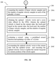
FIG. 3A depicts geometric representation for local goal computation by the robotic agent for a sensing range of an attached sensor, in accordance with some embodiments of the present disclosure. -
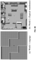
FIGS. 3B and 3C depict two simulation worlds experienced by the robotic agent during navigation towards a goal position, in accordance with some embodiments of the present disclosure. -
FIGS. 4 through 7 , andFIG. 9 depict simulation and experimental results for TurtleBot3 Waffle Pi™ robotic agent implementing the simultaneous local path planning and learning of the method ofFIG. 2 , in accordance with some embodiments of the present disclosure. -
FIG. 8 depicts a third world and corresponding two dimensional (2D) local cost map for the experiments on the TurtleBot3 Waffle Pi™ robotic agent implementing the simultaneous local path planning and learning of the method ofFIG. 2 , in accordance with some embodiments of the present disclosure. - It should be appreciated by those skilled in the art that any block diagrams herein represent conceptual views of illustrative systems and devices embodying the principles of the present subject matter. Similarly, it will be appreciated that any flow charts, flow diagrams, and the like represent various processes which may be substantially represented in computer readable medium and so executed by a computer or processor, whether or not such computer or processor is explicitly shown.
- Exemplary embodiments are described with reference to the accompanying drawings. In the figures, the left-most digit(s) of a reference number identifies the figure in which the reference number first appears. Wherever convenient, the same reference numbers are used throughout the drawings to refer to the same or like parts. While examples and features of disclosed principles are described herein, modifications, adaptations, and other implementations are possible without departing from the scope of the disclosed embodiments.
- Path planning for a mobile robot is the process of finding a sequence of valid collision-free configurations to transport the mobile robot from one position to another. Global path planning algorithm offers path between start and goal on a given world in offline. In order to deal with the environmental uncertainties (e.g., amendment of stationary object/obstacle in the world), global planner requires frequent replanning. Hence, global planners are computationally expensive. On the other hand, a local planner works on local environment, which is created locally within sensing range, and does not include any global information. Hence, the robot may be stuck in local minima as shown by state-of-the art. However, the computational cost of the local path planning algorithm is less as compared to the global path planning algorithm. Naturally, the local path planning algorithms in the art are capable enough to deal with frequent changes in the surroundings. One of the initial local path planning approaches is introduced as a curvature velocity method. The basics of the curvature velocity method is maximizing an objective function by choosing one suitable velocity sample (satisfying necessary constraints) from a velocity space. Based on the curvature velocity method, the concept of dynamic window approach (DWA) is derived by another existing work. The dynamic window is defined on the basis of the kinematics model and current velocity of the robot. A score is computed by selecting each velocity sample from the dynamic window as a function of robot's goal heading, velocity, and distance from the nearest obstacle. The velocity sample with maximum score value is selected for execution. Improvement of DWA is done by another existing method for better navigation capabilities in partially unknown environments among obstacles. Some works further proposed a Global DWA in order to avoid trapping in local minima. Besides several improvements of DWA, following technical limitations of DWA are specified in the literature. Firstly, the evaluation functions are not sufficient to identify potential velocity sample in the dynamic window. Hence, potential velocity sample may be ignored. Secondly, the score function is weighted sum of evaluation functions, and performance of the DWA highly depends on the choice of weight values. Former hindrances are circumvented by employing reinforcement learning and by deep reinforcement learning in the recent works in the art. However, these recent approaches require offline learning or training with a priori training data. Additionally, dimension of Q-table is defined a priori in the works in literature. To circumvent the said bottleneck (i.e., offline learning, a priori training data for learning and predefined Q-table dimension) of learning algorithm, simultaneous learning and planning algorithm (SLPA) is proposed in the art. However, the SLPA works for a fixed start and goal pair and needs to reinitialize if start and/or goal are/is altered. On the other hand, in local planning start and local goal keep on changing. So, local planning by employing SLPA is not feasible.
- Embodiments herein disclose a method and system for robotic navigation with simultaneous local path planning and learning by a robotic agent. The method discloses an approach that enables the robotic agent, also referred as mobile robot or robot interchangeably, to learn and plan simultaneously, based on SLPA in sensing range (SLPA-SR) approach, a wherein learning and planning techniques are synergistically combined to assist each other and improve the overall navigational performance of the robot. The planner acts as an actuator and helps to balance exploration and exploitation in the learning algorithm. The synergy between dynamic window approach (DWA) as a planning technique and a disclosed Next best Q-learning (NBQ) as a learning technique offers an efficient local planning approach. Further, unlike the traditional Q-learning, dimension of Q-tree in the NBQ is dynamic and does not require to define a priori.
- Referring now to the drawings, and more particularly to
FIGS. 1A through 9 , where similar reference characters denote corresponding features consistently throughout the figures, there are shown preferred embodiments and these embodiments are described in the context of the following exemplary system and/or method. -
FIG. 1A is a functional block diagram of asystem 100, interchangeably referred to as arobotic agent 100, for robotic navigation with simultaneous local path planning and learning, in accordance with some embodiments of the present disclosure. In an embodiment, thesystem 100 includes a processor(s) 104, communication interface device(s), alternatively referred as input/output (I/O) interface(s) 106, and one or more data storage devices or amemory 102 operatively coupled to the processor(s) 104. Thesystem 100 with one or more hardware processors is configured to execute functions of one or more functional blocks of thesystem 100. Further the robotic agent is integrated with a sensor, for example a light detection and ranging LiDAR, (not shown) to sense the environment of the robot during navigation towards a goal position. - Referring to the components of
system 100, in an embodiment, the processor(s) 104, can be one ormore hardware processors 104. In an embodiment, the one ormore hardware processors 104 can be implemented as one or more microprocessors, microcomputers, microcontrollers, digital signal processors, central processing units, state machines, logic circuitries, and/or any devices that manipulate signals based on operational instructions. Among other capabilities, the one ormore hardware processors 104 are configured to fetch and execute computer-readable instructions stored in thememory 102. In an embodiment, thesystem 100 can be implemented in a variety of computing systems including laptop computers, notebooks, hand-held devices such as mobile phones, workstations, mainframe computers, servers, and the like. - The I/O interface(s) 106 can include a variety of software and hardware interfaces, for example, a web interface, a graphical user interface, and the like and can facilitate multiple communications within a wide variety of networks N/W and protocol types, including wired networks, for example, LAN, cable, etc., and wireless networks, such as WLAN, cellular and the like. In an embodiment, the I/O interface (s) 106 can include one or more ports for connecting to a number of external devices or to another server or devices.
- The
memory 102 may include any computer-readable medium known in the art including, for example, volatile memory, such as static random access memory (SRAM) and dynamic random access memory (DRAM), and/or non-volatile memory, such as read only memory (ROM), erasable programmable ROM, flash memories, hard disks, optical disks, and magnetic tapes. - In an embodiment, the
memory 102 includes a plurality ofmodules 110. The plurality ofmodules 110 include programs or coded instructions that supplement applications or functions performed by thesystem 100 for executing different steps involved in the process of robotic navigation with simultaneous local path planning and learning, being performed by thesystem 100. The plurality ofmodules 110, amongst other things, can include routines, programs, objects, components, and data structures, which performs particular tasks or implement particular abstract data types. The plurality ofmodules 110 may also be used as, signal processor(s), node machine(s), logic circuitries, and/or any other device or component that manipulates signals based on operational instructions. Further, the plurality ofmodules 110 can be used by hardware, by computer-readable instructions executed by the one ormore hardware processors 104, or by a combination thereof. The plurality ofmodules 110 can include various sub-modules (not shown) such as modules executing the DWA and the NBQ as depicted inFIG. 1B . Further, thememory 102 may comprise information pertaining to input(s)/output(s) of each step performed by the processor(s) 104 of the system100 and methods of the present disclosure. Further, thememory 102 includes adatabase 108. The database (or repository) 108 may include a plurality of abstracted piece of code for refinement and data that is processed, received, or generated as a result of the execution of the plurality of modules in the module(s) 110, for example, a 2D floor plan, a goal position, a plurality of way points to reach the goal positions, the Q-tree, the local goals, a plurality of states visited by the robotic agent and so on. Although thedata base 108 is shown internal to thesystem 100, it will be noted that, in alternate embodiments, thedatabase 108 can also be implemented external to thesystem 100, and communicatively coupled to thesystem 100. The data contained within such external database may be periodically updated. For example, new data may be added into the database (not shown inFIG. 1A ) and/or existing data may be modified and/or non-useful data may be deleted from the database. In one example, the data may be stored in an external system, such as a Lightweight Directory Access Protocol (LDAP) directory and a Relational Database Management System (RDBMS). Functions of the components of thesystem 100 are now explained with reference toFIG. 1B through FIG. 9 . -
FIG. 1B illustrates high level process flow of thesystem 100 ofFIG. 1A , in accordance with some embodiments of the present disclosure. -
FIGS. 2A through 2B (collectively referred asFIG. 2 ) is a flow diagram illustrating amethod 200 for robotic navigation with simultaneous local path planning and learning, using the system depicted inFIG. 1A andFIG. 1B , in accordance with some embodiments of the present disclosure. - In an embodiment, the
system 100 comprises one or more data storage devices or thememory 102 operatively coupled to the processor(s) 104 and is configured to store instructions for execution of steps of themethod 200 by the processor(s) or one ormore hardware processors 104. The steps of themethod 200 of the present disclosure will now be explained with reference to the components or blocks of thesystem 100 as depicted inFIG. 1A andFIG. 1B and the steps of flow diagram as depicted inFIG. 2 . Although process steps, method steps, techniques or the like may be described in a sequential order, such processes, methods, and techniques may be configured to work in alternate orders. In other words, any sequence or order of steps that may be described does not necessarily indicate a requirement that the steps to be performed in that order. The steps of processes described herein may be performed in any order practical. Further, some steps may be performed simultaneously. - Referring to the steps of the
method 200, atstep 202 of themethod 200, therobotic agent 100, executed by one ormore hardware processors 104, perform a global path planning to obtain a plurality of way points to reach a goal position based on a current position, the goal position and two-dimensional (2D) floor plan of an environment the robotic agent is deployed into, wherein the current position of the robotic agent represents a current way point. - At
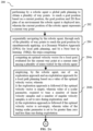
step 204 of themethod 200, of therobotic agent 100, executed by the one ormore hardware processors 104, sequentially navigates through each of the plurality of way points to reach the goal position by simultaneously applying a) a Dynamic Window Approach (DWA) for a local path planning, and b) a Next best Q-learning (NBQ) approach that enables real-time learning while balancing between an exploitation approach and an exploration approach. Sequentially navigating through each of the plurality of way points to reach the goal position comprises iteratively performing a plurality of steps (204a though 204f as listed below) until the plurality of way points are covered. - a) Computing an optimal velocity vector for a local goal evaluated for the current way point at a current state among a plurality of states visited by the robotic agent (204a). Each of the plurality of states is a tuple comprising a sector within sensing range of the sensor (for example, a LiDAR) attached to the robotic agent, a current linear velocity of the robotic agent, and a current angular velocity of the robotic agent.
- b) Employing, by the robotic agent, one of an exploration approach and an exploitation approach for the local path planning based on the optimal velocity vector (204b). Further,
- i) The exploration approach is followed if the optimal velocity vector is empty. Value of a scalar parameter, required to tune a number of linear velocity samples and a number of angular velocity samples, is set to zero during the exploration approach.
- ii) The exploitation approach is followed if the optimal velocity vector is not-empty, The value of the scalar parameter is set to be greater than zero and less than one during the exploitation approach;
- c) Computing the number of linear velocity samples and the number of angular velocity samples at each of the plurality of states based on value set for the scalar parameter (204c).
- d) Obtaining the optimal velocity vector and a score value for each velocity sample offered by the DWA based on the current state, the local goal, the number of linear velocity samples, and the number of angular velocity samples (204d).
- e) Evaluating a reward using a predefined reward function and updating a Q-value of a Q-tree (204e). The Q-value adapts based on one or more uncertainties in the environment. The Q-value is summation of immediate reward and discounted next best Q-value. An alpha is the learning rate to balance between an old and a new Q-value. The dimension of the Q-tree in the NBQ is dynamically obtained without need to define a priori.
- f) Recomputing the optimal velocity vector at the current state with the updated Q-tree and executing the optimal velocity vector to update the current waypoint by current position of the robotic agent (204f).
- Thus,
method 200 employs synergistic combination of the DWA for planning and the disclosed NBQ for learning. In NBQ, a state is the tuple consisting of sector within sensing range of the sensor attached to the robotic agent (robot) and current velocity vector of the robotic agent. Action is the velocity sample chosen from the dynamic window. Unlike traditional DWA, the number of linear and angular velocity samples are computed by the disclosed action selection strategy. For each velocity sample one score value is computed, ignoring the robot's distance from the nearest obstacle which is captured by the rewarding mechanism in the NBQ. The computed Q-values in the NBQ can adapt dynamically based on the environmental uncertainties. Over the iteration, requirement of the DWA is reduced and robot becomes more dependent on the learned NBQ-values for optimal velocity sample selection at current state. - The
method 200 is now explained with reference toFIG. 1B with supporting mathematical explanation and pseudocode. - PRELIMINARIES: Considering dynamic window approach (DWA) [as the planning algorithm] and the disclosed NBQ-learning as learning algorithm, the preliminaries section briefly explains the DWA to improve legibility. The DWA generates linear velocity (v) and angular velocity (ω) to control a robot for a finite sampling time, say Δt. The selection of optimal velocity vector: (v*,ω*) from a set of velocity vectors is twofold. First fold is about generating the set of feasible velocity vectors, Vr . Second fold is about the selection of (v*,ω*) from Vr .
- 1) Generating feasible velocity space: Feasible velocity space is denoted by Vr = Vs ∩ Vd ∩ Vad, where Vs, Vd and Vad are velocity space satisfies
condition 1, condition 2 andcondition 3 respectively.- Condition 1: After pruning complete velocity vectors by vmin ≤ v ≤ vmax and ωmin ≤ ω ≤ ωmax the remained velocity vector is referred as Vs . Here, max and min in the suffix of nomenclature are the corresponding maximum and minimum limitation respectively.
- Condition 2: The set of velocity vectors Vd reachable from robot's current velocity vector (va ,ωa ) within time horizon Δt is defined by va-amax Δt ≤ v ≤ va +amax Δt and ωa-αmax Δt ≤ ω ≤ ωa+αmax Δt and is also named as dynamic window. Here, amax and αmax are the maximum possible linear and angular accelerations respectively for the robot.
- Condition 3: The admissible velocity vectors Vad is the collection of collision free velocity vectors by satisfying v ≤


- 2) Selecting the optimal velocity vector from Vr: Let, Vr consists of Nvr as linear and Nwr as angular velocity samples. Total velocity samples Nr can be represented as a Nvr ×Nωr window. For each velocity sample, (v,ω) a score function J(v,ω) is evaluated by equation (1) below.

- PROBLEM FORMULATION: Online planning or offline learning based planning is the key for any successful navigation from a given position to another. Online planning suffers from repeated planning for minor positional modifications. Learning circumvents this repeated planning by learning the action (e.g., velocity vector) for the minor positional modifications. Unfortunately, existing learning algorithms either work in offline or requires a priori training data. The disclosed
method 200 synergistically combines the planning (here DWA) and the learning (here the disclosed NBQ) algorithms. - The method 200: as depicted in
FIG. 1B , blocks within the dotted section are generating one local goal. Local goal computation is done with the help of sensor's sensing range and global path (sequence of plurality of waypoints from start position of the robot to goal) offered by the global path planner. Input to the global path planner is a 2D floor plan, start and goal location as shown inFIG. 1B . The main building blocks (marked as double lined blocks inFIG. 1B ) of themethod 200 are DWA (planning module), the disclosed NBQ (learning module) and one Q-tree (records Q-value of NBQ at each state-action pair). The block DWA for exploration refers DWA is planning with maximum possible velocity samples for exploration. On the other hand, the block DWA for exploitation refers DWA is planning with minimum number of velocity samples to exploit Q-tree. In any case, actuation by the DWA assists the NBQ to update Q-tree. Finally, the NBQ offers one optimal velocity sample for execution. Detail description of the disclosedmethod 200 is provided below after describing the methodology of local goal computation. - Local Goal Computation: Consider a sensor with sensing range of rsensor. A local goal denoted by lg is computed for two situations. In
situation 1, next waypoint say P 1 is within rsensor and in the situation 2, P 1 is outside of rsensor. Forsituation 1, P 1 is the local goal and is expressed by equation (2) below. For situation 2, a vector OP1 between robot's current position, say, O and P 1 is formed. The unit vector corresponds to OP1 is given by


- Next Best Q-learning (NBQ): In the learning algorithm NBQ, Q-value at a state due to an action is the summation of immediate reward and the Q-value corresponds to the next best action at the said state. This process continues recursively to update Q-values at each state for various actions. The immediate reward in NBQ is adapted based on the pruned score function, i.e., score without considering changes of static object/obstacle in the world (β×dist(v,ω)) as shown in equation (3) below. Motivation of pruning score function is to deal with the environmental amendments by NBQ and acts in real-time. The computed Q-values are recorded for future reference.

- Like Q-learning, in the disclosed NBQ, selection of state, action and design of reward function are very important. Hence, the said parameters are discussed in the subsequent sections.
- 1) State: State is denoted by s =< qk, va, ωa >, where qk is the sector within sensing range and (va, ωa ) is the robot's current velocity vector. Each (va, ωa ) falls within one among multiple discrete ranges defined over Vr (feasible velocity space). To define qk, the entire sensing range is equally partitioned into a number of regions, where each region is one sector. Say, the horizontal sensing range αh is equally partitioned into n number of sectors denoted by qk, k ∈ [1,...,n]. Each qk lies between angle θ k-1 and θk,k E [1,...,n]. Angle covered by qk is (θk -θ k-1), here θk > θ k-1 . The maximum angle covered by qk is denoted by θmax , and is shown in
FIG. 3A , where w is the robot's width. Now θmax is expressed by equation (4), where 'e' is the clearance. Robot needs at least w unit arc length with a clearance of e on both sides to navigate as shown inFIG. 3A .

- 2) Action: Let action a ∈ A at state (s) is <v,ω>, where v and ω are the linear and angular velocities respectively offered by the DWA satisfying the
condition 1, condition 2 andcondition 3 at current state to reach next state. - 3) Reward: It is apparent from equation (3) that the pruned score is function of action a =<v,ω> only. The action a is executed from a state, say 's' Naturally, the score value offered by equation (3) because of the same 'a' from another state (say 's') are not identical. This infers that the score value offered by equation (3) is the function of both s and a, i.e.,
 be the score at state 's' because of optimal action a*.


- 4) Next Best Q-Learning (NBQ)-value: Let, Q-value at s because of an action a is denoted by Q(s,a). In the disclosed NBQ, Q(s,a) adapts according to the variation of r(s,a). The value of r(s,a) varies with the variation of


- 1) Receive score, from DWA at (s,a)

- 2) Find next best score of say


- 3) Get action corresponds to i.e., a'

- 4) Obtain Q-value at (s,a') from Q-tree, i.e., Q(s,a')
- 5) If Q(s,a') > 0, then NBQ(s,a) = Q(s,a')
method 200 using the SLPA-SR approach reduces frequency of invoking DWA as learning progresses, which indeed beneficial for real-time planning. For planning at s, the optimal action a* is computed by equation (9) below. However, if any feasible action is not found, then DWA is invoked for exploration.
- 1) Receive score,
- 5) Balancing Exploration and Exploitation in NBQ: The DWA acts as an actuator in the disclosed NBQ. Actuation of DWA depends on the number of velocity samples selected from the dynamic window. An attempt is made to design an expression, which can compute the number of velocity samples by tuning one scalar parameter (c). Hence, unlike DWA described earlier, here number of velocity samples nr (s) = nvr (s) × nωr (s) at each state (s) is computed, where nvr (s) and nωr (s) are the linear and angular velocity samples respectively. The expression for nvr (s) and nωr (s) respectively are given by equations (10) and (11) below. In equations (10) and (11) vinit and ωinit are the initial linear and angular velocity sample count for DWA respectively. Also (fv +vinit ) = Nvr, (fω + ωinit ) = Nωr and Nvr × Nωr = Nr. Gradually vinit and ωinit exponentially decrease with the value of x(s), where x(s) is the number of times the robot visits the state (s). Finally, with the increase of x(s) the value of nvr (s) and nωr (s) converges to 0 < fv << vinit and 0 < fω << ωinit respectively to keep exploring nature of the disclosed NBQ at s.


- 6) Convergence of NBQ: Explained below are few theorems with proofs.
- i. Theorem 1 (deals with the convergence of the disclosed NBQ) - The disclosed NBQ converges at each state action pair as time t → ∞.
- Proof: Let, Qt (s,a) be the actual Q-value at (s,a) after t iteration and after infinite iteration Qt (s,a) attains true Q-value, i.e., Q(s,a). The error in Q-value at (s,a) after t iteration is given by Δ t (s,a). Assumption 4.1 is made to establish converge of the disclosed NBQ.
-
Assumption 1 of theorem 1: The actual and true value of r(s,a) at an iteration for any environmental condition are identical.
- It is apparent from equation (12) that Δ t is separated into two parts: Δ t-1(s,a) and Δ t-1(s,a'). It is also apparent from equation (12) that in each iteration Δ t-1(s,a) is getting multiplied by a
factor 0 ≤ (1 - α) < 1, ∵ 0 < α ≤ 1. Now, say at first iteration maximum error contribution for the first part at (s,a) is Δ0(s,a). Then after t iteration one can write that
- As t → ∞, Δ t (s,a) → 0. Similarly, αyΔ t-1(s,a') can be expressed for (s,a'), and similar inference can be made as done in equation (13) ∵ 0 ≤ γ < 1 and 0 < α ≤ 1. Hence, the disclosed NBQ converges ∀(s,a) with zero error as t → ∞.
- The method 200: As depicted in
FIG. 1B and steps ofFIG. 2 , themethod 200 computes global path offered by A* using start, goal positions and 2D floor plan as inputs. After that, robot attempts to visit each waypoint offered by the A* from robot's current position, say p. To visit one waypoint robot needs to evaluate corresponding lg and associated qk. Then current state, s =< qk, va, ωa > is formed. From s, robot attempts to compute a* by equation (9). In case, a* = Ø, robot attempts for pure exploration setting c = 0. For a* ≠ Ø, robot starts exploitation setting 0 < c < 1. Based on the value of c, nvr (s) and nωr (s) are computed and fed into the DWA for actuation. Because of this actuation (say a)r(s,a) and Q(s,a) are updated. Finally, a* is recomputed for execution at s. The updated p is compared with the waypoint offered by A* and this whole process is repeated. Pseudo-code1 is provided below for the
method 200. -


- ANALYSIS: The SLPA-SR implemented by the
method 200 is analyzed in terms of computational cost by considering DWA as proposed in D. Fox, W. Burgard, and S. Thrun, "The dynamic window approach to collision avoidance, " IEEE Robotics & Automation Magazine, vol. 4, no. 1, pp. 23-33, 1997 as the contender algorithm. Computational cost for one optimal velocity vector generation at state (s) by The SLPA-SR involves computation cost for the planner (DWA) and computation cost for the learner (NBQ). The cited DWA involves nr (s) score computation (pruned score offered by equation (3)) and compares (nr (s) - 1) scores to evaluate the best score. Here, nr (s) is the number of velocity samples chosen from dynamic window at state (s). In the disclosed NBQ-learning, robot computes NBQ-values with maximum of (Nr (s)-1) number of score comparison and finally, selects the optimal velocity vector by doing maximum (Nr (s)-1) number of Q-value comparisons. Here, Nr (s) is the maximum value of nr (s). Say, tl (s) be the computational cost for one time optimal velocity vector generation by the SLPA-SR at s and based on the above discussion tl (s) is expressed below.


- Again referring equation (10) and equation (11), as t → ∞ with the increase in x(s) the value of nr (s) converges to fvf ω << Nr. Again, by equation (14),

- Hence, it can be concluded that tl (s) < tp (s) at s.
- SIMULATION AND EXPERIMENT: Demonstrated are simulation and experimental results in three steps. First step simulates the SLPA-SR and contender (DWA) algorithm in a zigzag environment (world 1) of dimension 16m × 13m with lane width of 3.5m using TurtleBot3 Waffle Pi™. The simulation is performed using Turtlebot3: Robot simulation made easy, (last accessed 16th February 2023). [Online]. Available: https://www.turtlebot.com/about/. Second step is about simulation of the disclosed The
method 200 and DWA, in a typical warehouse environment (world 2) of dimension 30m×20m using TurtleBot3 Waffle Pi. Finally, one real experiment is conducted using TurtleBot3 Waffle Pi™ in a zigzag environment (world 3) of dimension 3.6m×2.4m with lane width of 1.2m by exploiting the learned Q-tree from world 2. Python implementation of DWA is taken from A. Sakai, D. Ingram, J. Dinius, K. Chawla, A. Raffin, and A. Paques, "Pythonrobotics: a python code collection of robotics algorithms, " arXiv preprint arXiv:1808.10703, 2018 . The performance metrics include average run-time, linear velocity, angular velocity, % of exploitation, average reward, state-action pair count. Performance metric linear velocity, angular velocity and average run-time are employed to confirm superiority of the disclosed The SLPA-SR over the contender algorithm (DWA). Remaining performance metrics are employed to establish efficacy of the SLPA-SR. -
- 1) Simulation: Simulation of
Pseudocode 1 is conducted in a workstation with an Intel Core i7-9700K CPU@ 3.60GHz * 8 processor™ and 16GB of RAM having Ubuntu 20.04.4 LTS™ as operating system.Pseudocode 1 is implemented using Python 3.8 and simulated on Robot Operating System (ROS) Noetic™ with Gazebo™ for TurtleBot3 Waffle Pi™. TurtleBot3 Waffle Pi™ is equipped with 360° 2D LiDAR to perceive real-time uncertainties from the world. Over the iteration uncertain obstacles are introduced randomly in (a) world 1 (zigzag) and (b) world 2 ( typical warehouse) ofFIG. 3B . An inflation of 0.2m is considered for simulation. Velocity and acceleration ranges are ±0.2m/sec and ±0.5m/sec 2, respectively. Following parameters are set inPseudocode 1 for simulation: fv = 20,fω = 3, vinit = 100, ωinit = 10, c = 0.05 for exploitation using DWA,ε = 0.5m, α = 0.1, γ
0.9,α' = 15,γ' = 0.9, Δt = 3sec, σ = 0.83 and clarence e = 0.2. - 2) Experiment: Hardware experiment is conducted using TurtleBort3 Waffle Pi™. TurtleBort3 Waffle Pi™ is equipped with one 360° 2D LiDAR. During navigation, real-time uncertainties are communicated with a ground station using one ad hoc wireless network. Ground station sends command velocities, computed by the disclosed The
method 200 or DWA to the TurtleBort3 Waffle Pi, via said wireless network. TurtleBot3 Waffle Pi receives command velocities through connecting the WiFi of Raspberry Pi™ (mounted on TurtleBot3 Waffle Pi™) to the said ad hoc WiFi network. Localization of the TurtleBort3 is done using OptiTrack-Motion Capture Systems™. Thepseudocode 1 employs same parameter setting for real-time experiment as employed in simulation. During uncertain obstacle avoidance velocity range is reduced to ±0.1m/sec from ±0.2m/sec. Also, an inflation of 0.25m is considered for hardware experiments. -
1) Simulation: Description of the performance metric are given below. Average run-time for Pseudocode 1 {algo∈[DWA, SLPA-SR]} is computed by equation (18) below. To compute average run-time, start, goal locations inworld 1, 2 are separately fixed and the simulations are repeated.

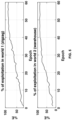
The % of exploitation (%E) at an epoch in SLPA-SR is given by:
method 200 at an epoch is computed by taking average of Q-values at all state action pairs.
2) Experiment: For hardware experiment using TurtleBot3 Waffle Pi™, one 2D floor plan of world 3 (depicted in inFIG. 8 (a) ) is created at the beginning of experiments using 3600 2D LiDAR equipped with the TurtleBot3 Waffle Pi™. The 2D floor plan is fed intoPseudocode 1. Q-tree, learned by TurtleBot3 Waffle Pi™ during simulation on world 2 of FIG. 3C, is imported to TurtleBot3 Waffle Pi™ for hardware experiment onworld 3 ofFIG. 8 . Randomly static obstacle is placed onworld 3 while navigating using TurtleBot3 Waffle Pi.FIG. 8 (b) depicts 2D local cost map ofworld 3 for experiments. TurtleBot3 Waffle Pi is placed at the origin ofworld 3Table I Average run-time analysis World Start Goal Randomly placed obstacle Epoch Algo Average run-time (sec) 1 (0, 0) (3, 6) 0 60 DWA 32.9907 method 200 (SLPA-SR) 31.5132 (0, 0) (10,6) 1 10 DWA 50.7337 method 20048.5605 (0, 0) (10,-6) 1 10 DWA 54.4768 method 20050.7555 (0, 0) (-10,6) 2 10 DWA 53.8211 2 method 20052.3395 (-10,6) (-10,-4) 3 10 DWA 82.3827 method 20080.1633 (-10,-4) (10,-6) 3 10 DWA 79.6911 method 20077.2029 random random 7 10 DWA 55.1072 method 20054.1522 - Experimental results for TurtleBot3 Waffle Pi™.
- 1) Simulation: Table I above lists average run-time for simulations conducted with the TurtleBot3 Waffle Pi in
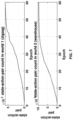
world 1 and 2. It is apparent from Table I that the disclosed method 200 (SLPA-SR) is outperforming the contender algorithm (i.e., DWA) in terms of average run-time for bothworld 1 and 2. Inworld 1, themethod 200 is tested with one pair of start-goal without any obstacle for 60 epochs. In world 2, themethod 200 is tested with six sets of start-goal pairs. For each start-goal pair, after 5 epochs static object/obstacle is placed randomly on global path. The remaining five epochs are tested with the randomly placed static object/obstacle as shown in Table I. Table I is also supporting equations (16) and (17).FIG. 4 shows the variation of linear and angular velocities (at 7th epoch) of TurtleBot3 Waffle Pi™ during simulation in world 2 with (0,0) as start and (10,6) as goal locations and one randomly placed obstacle. It is apparent fromFIG. 4 that the disclosed Themethod 200 is offering better velocity profiles compared to the same by the DWA. It is also apparent fromFIG. 4 that Themethod 200 has reached goal in less time compared to the same by DWA.FIG. 4 again validates equations (16) and (17). The plot for % of exploitation (%E) is shown inFIG. 5 . It is apparent fromFIG. 5 that the % of exploitation is monotonically increasing in nature with epoch. As count of exploitation is increasing, it can be inferred that the usage of planner (i.e., DWA) is decreasing with the increase in number of epochs. Average reward is also monotonically increasing in nature with epoch as shown inFIG. 6 for bothworld 1 and 2. Monotonic increment in state-action pair's count in the disclosed NBQ is also shown inFIG. 7 for bothworld 1 and 2. - 2) Experiment:
FIG. 8 (a) shows theworld 3 for experiment andFIG. 8 (b) shows 2D local cost map ofworld 3.FIG. 9 shows the real-time velocity plots from hardware experiments for themethod 200 and DWA. It is apparent fromFIG. 9 that the disclosedmethod 200 is offering better velocity profile compared to the same by DWA. Also, themethod 200 is taking less time compared to the DWA to reach the goal. - Unlike the exiting approaches that have a technical limitation of not able to perform planning and learning simultaneously in real-time, the method and system disclosed herein provides dynamic nature of the NBQ disclosed herein, i.e., number of state-action pair is dynamic in the Q-tree. Further, provides balancing of exploration-exploitation in the NBQ with ability to deal with environmental uncertainties.
- It is to be understood that the scope of the protection is extended to such a program and in addition to a computer-readable means having a message therein; such computer-readable storage means contain program-code means for implementation of one or more steps of the method, when the program runs on a server or mobile device or any suitable programmable device. The hardware device can be any kind of device which can be programmed including e.g., any kind of computer like a server or a personal computer, or the like, or any combination thereof. The device may also include means which could be e.g., hardware means like e.g., an application-specific integrated circuit (ASIC), a field-programmable gate array (FPGA), or a combination of hardware and software means, e.g., an ASIC and an FPGA, or at least one microprocessor and at least one memory with software processing components located therein. Thus, the means can include both hardware means, and software means. The method embodiments described herein could be implemented in hardware and software. The device may also include software means. Alternatively, the embodiments may be implemented on different hardware devices, e.g., using a plurality of CPUs.
- The embodiments herein can comprise hardware and software elements. The embodiments that are implemented in software include but are not limited to, firmware, resident software, microcode, etc. The functions performed by various components described herein may be implemented in other components or combinations of other components. For the purposes of this description, a computer-usable or computer readable medium can be any apparatus that can comprise, store, communicate, propagate, or transport the program for use by or in connection with the instruction execution system, apparatus, or device.
- Furthermore, one or more computer-readable storage media may be utilized in implementing embodiments consistent with the present disclosure. A computer-readable storage medium refers to any type of physical memory on which information or data readable by a processor may be stored. Thus, a computer-readable storage medium may store instructions for execution by one or more processors, including instructions for causing the processor(s) to perform steps or stages consistent with the embodiments described herein. The term "computer-readable medium" should be understood to include tangible items and exclude carrier waves and transient signals, i.e., be non-transitory. Examples include random access memory (RAM), read-only memory (ROM), volatile memory, nonvolatile memory, hard drives, CD ROMs, DVDs, flash drives, disks, and any other known physical storage media.
Claims (4)
- A method for robot navigation, the method further comprising:performing (202), by a robotic agent executed by one or more hardware processors, a global path planning to obtain a plurality of way points to reach a goal position based on a current position, the goal position and two-dimensional (2D) floor plan of an environment the robotic agent is deployed into, wherein the current position of the robotic agent represents a current way point; andsequentially navigating (204), by the robotic agent, through each of the plurality of way points to reach the goal position by simultaneously applying a) a Dynamic Window Approach (DWA) for a local path planning, and b) a Next best Q-learning (NBQ) approach that enables real-time learning while balancing between an exploitation approach and an exploration approach, wherein sequentially navigating through each of the plurality of way points to reach the goal position comprises iteratively performing a plurality of steps until the plurality of way points are covered, the plurality of steps further comprising:a) computing an optimal velocity vector for a local goal evaluated for the current way point at a current state among a plurality of states visited by the robotic agent (204a);b) employing, by the robotic agent, one of an exploration approach and an exploitation approach for the local path planning based on the optimal velocity vector (204b), whereini) the exploration approach is followed if the optimal velocity vector is empty, wherein value of a scalar parameter, required to tune a number of linear velocity samples and a number of angular velocity samples, is set to zero during the exploration approach, andii) the exploitation approach is followed if the optimal velocity vector is not-empty, wherein value of the tuning scalar parameter is set to be greater than zero and less than one during the exploitation approach;c) computing the number of linear velocity samples and the number of angular velocity samples at each of the plurality of states based on value set for the scalar parameter (204c);d) obtaining the optimal velocity vector and a score value for each velocity sample offered by the DWA based on the current state, the local goal, the number of linear velocity samples, and the number of angular velocity samples (204d);e) evaluating a reward using a predefined reward function and updating a Q-value of a Q-tree (204e), wherein the Q-value adapts based on one or more uncertainties in the environment, wherein by the NBQ approach, the Q-value at a particular state of the plurality of states due to an action is a summation of immediate reward and a discounted next best Q-value, wherein the discounted next best Q-value is the Q-value corresponding to a next best action at the particular state, wherein the Q-values is updated recursively at each state for the plurality of actions, wherein the immediate reward is adapted based on a pruned score function without considering changes of static obstacle in the environment, and wherein the pruned score function is adapted to deal with environmental amendments by the NBQ approach in real-time; andf) recomputing the optimal velocity vector at the current state with the updated Q-tree and executing the optimal velocity vector to update the current waypoint by current position of the robotic agent (204f).
- The method of claim 1, wherein each of the plurality of states is a tuple further comprising a sector within sensing range of a sensor attached to the robotic agent, a current linear velocity of the robotic agent, and a current angular velocity of the robotic agent.
- A robotic agent (100) for robot navigation, the robotic agent (100) further comprising:a memory (102) storing instructions;one or more Input/Output (I/O) interfaces (106); andone or more hardware processors (104) coupled to the memory (102) via the one or more I/O interfaces (106), wherein the one or more hardware processors (104) are configured by the instructions to:perform a global path planning to obtain a plurality of way points to reach a goal position based on a current position, the goal position and two-dimensional (2D) floor plan of an environment the robotic agent is deployed into, wherein the current position of the robotic agent represents a current way point; andsequentially navigate through each of the plurality of way points to reach the goal position by simultaneously applying a) a Dynamic Window Approach (DWA) for a local path planning, and b) a Next best Q-learning (NBQ) approach that enables real-time learning while balancing between an exploitation approach and an exploration approach, wherein sequentially navigating through each of the plurality of way points to reach the goal position comprises iteratively performing a plurality of steps until the plurality of way points are covered, the plurality of steps further comprising:a) computing an optimal velocity vector for a local goal evaluated for the current way point at a current state among a plurality of states visited by the robotic agent;b) employing, by the robotic agent, one of an exploration approach and an exploitation approach for the local path planning based on the optimal velocity vector, whereini) the exploration approach is followed if the optimal velocity vector is empty, wherein value of a scalar parameter, required to tune a number of linear velocity samples and a number of angular velocity samples, is set to zero during the exploration approach, andii) the exploitation approach is followed if the optimal velocity vector is not-empty, wherein value of the tuning scalar parameter is set to be greater than zero and less than one during the exploitation approach;c) computing the number of linear velocity samples and the number of angular velocity samples at each of the plurality of states based on value set for the scalar parameter;d) obtaining the optimal velocity vector and a score value for each velocity sample offered by the DWA based on the current state, the local goal, the number of linear velocity samples, and the number of angular velocity samples;e) evaluating a reward using a predefined reward function and updating a Q-value of a Q-tree, wherein the Q-value adapts based on one or more uncertainties in the environment, wherein by the NBQ approach, the Q-value at a particular state of the plurality of states due to an action is a summation of immediate reward and a discounted next best Q-value , wherein the discounted next best Q-value is the Q-value corresponding to a next best action at the particular state, wherein the Q-values is updated recursively at each state for the plurality of actions, wherein the immediate reward is adapted based on a pruned score function without considering changes of static obstacle in the environment, and wherein the pruned score function is adapted to deal with environmental amendments by the NBQ approach in real-time; andf) recomputing the optimal velocity vector at the current state with the updated Q-tree and executing the optimal velocity vector to update the current waypoint by current position of the robotic agent.
- The robotic agent of claim 3, wherein state is a tuple further comprising a sector within sensing range of a sensor attached to the robotic agent, a current linear velocity of the robotic agent, and a current angular velocity of the robotic agent.
Applications Claiming Priority (1)
| Application Number | Priority Date | Filing Date | Title |
|---|---|---|---|
| IN202321021088 | 2023-03-24 |
Publications (3)
| Publication Number | Publication Date |
|---|---|
| EP4435549A1 EP4435549A1 (en) | 2024-09-25 |
| EP4435549B1 true EP4435549B1 (en) | 2025-04-30 |
| EP4435549C0 EP4435549C0 (en) | 2025-04-30 |
Family
ID=89661993
Family Applications (1)
| Application Number | Title | Priority Date | Filing Date |
|---|---|---|---|
| EP24152871.0A Active EP4435549B1 (en) | 2023-03-24 | 2024-01-19 | Robotic navigation with simultaneous local path planning and learning |
Country Status (2)
| Country | Link |
|---|---|
| US (1) | US12585285B2 (en) |
| EP (1) | EP4435549B1 (en) |
Families Citing this family (3)
| Publication number | Priority date | Publication date | Assignee | Title |
|---|---|---|---|---|
| CN120074626B (en) * | 2025-01-24 | 2025-08-22 | 四川大学 | A communication path planning method for large-scale low-orbit constellation with sudden interference |
| CN119984290A (en) * | 2025-04-15 | 2025-05-13 | 青岛杰瑞自动化有限公司 | A path planning method and system based on deep reinforcement learning, and electronic equipment |
| CN120993921B (en) * | 2025-10-16 | 2026-01-30 | 青岛大学 | Humanoid robot motion control method based on footprint planning |
Family Cites Families (5)
| Publication number | Priority date | Publication date | Assignee | Title |
|---|---|---|---|---|
| CN108829134A (en) * | 2018-07-03 | 2018-11-16 | 中国船舶重工集团公司第七〇九研究所 | A kind of real-time automatic obstacle avoiding method of deepwater robot |
| US12399501B2 (en) | 2020-12-10 | 2025-08-26 | AI Incorporated | Method of lightweight simultaneous localization and mapping performed on a real-time computing and battery operated wheeled device |
| CN112506199B (en) | 2020-12-12 | 2022-12-02 | 江西洪都航空工业集团有限责任公司 | Local path planning method based on dynamic window method and suitable for Ackerman model robot |
| WO2022216232A1 (en) * | 2021-04-08 | 2022-10-13 | Nanyang Technological University | Methods and systems for shared control of goal directed wheelchair navigation |
| CN114564016A (en) * | 2022-02-24 | 2022-05-31 | 江苏大学 | Navigation obstacle avoidance control method, system and model combining path planning and reinforcement learning |
-
2024
- 2024-01-19 EP EP24152871.0A patent/EP4435549B1/en active Active
- 2024-01-19 US US18/417,504 patent/US12585285B2/en active Active
Also Published As
| Publication number | Publication date |
|---|---|
| EP4435549C0 (en) | 2025-04-30 |
| US12585285B2 (en) | 2026-03-24 |
| EP4435549A1 (en) | 2024-09-25 |
| US20240319735A1 (en) | 2024-09-26 |
Similar Documents
| Publication | Publication Date | Title |
|---|---|---|
| EP4435549B1 (en) | Robotic navigation with simultaneous local path planning and learning | |
| Min et al. | RNN-based path prediction of obstacle vehicles with deep ensemble | |
| EP3748455B1 (en) | A method and a system for hierarchical network based diverse trajectory proposal | |
| Claes et al. | Multi robot collision avoidance in a shared workspace | |
| Pérez-Higueras et al. | Teaching robot navigation behaviors to optimal RRT planners | |
| Bonetto et al. | irotate: Active visual slam for omnidirectional robots | |
| Shiarlis et al. | Rapidly exploring learning trees | |
| EP3685968B1 (en) | Robot motion planning in manufacturing | |
| Elizondo-Leal et al. | The exact Euclidean distance transform: a new algorithm for universal path planning | |
| Lei et al. | A bio-inspired neural network approach to robot navigation and mapping with nature-inspired algorithms | |
| CN118092413B (en) | Path planning method, terminal and storage medium for multi-robot system | |
| Kim et al. | Learning forward dynamics model and informed trajectory sampler for safe quadruped navigation | |
| Guo et al. | Safe path planning with gaussian process regulated risk map | |
| Kitanov et al. | Topological belief space planning for active SLAM with pairwise Gaussian potentials and performance guarantees | |
| Hoerger et al. | Adaptive discretization using voronoi trees for continuous-action pomdps | |
| Xu et al. | Online motion planning of mobile cable-driven parallel robots for autonomous navigation in uncertain environments | |
| Bhargava et al. | An omnidirectional mecanum wheel automated guided vehicle control using hybrid modified A* algorithm | |
| Essaky et al. | ARReSVG: Intelligent Multi-UAV Navigation in Partially Observable Spaces Using Adaptive Deep Reinforcement Learning Approach | |
| EP3797939B1 (en) | Control command based adaptive system and method for estimating motion parameters of differential drive vehicles | |
| Oliveira et al. | Augmented vector field navigation cost mapping using inertial sensors | |
| Jin et al. | APPA: An adaptation path planning algorithm for real-time obstacle avoidance in multi-robot systems | |
| Huh et al. | Learning to generate cost-to-go functions for efficient motion planning | |
| Vaněk et al. | Multi-goal trajectory planning with motion primitives for hexapod walking robot | |
| Sugiyama et al. | Value function approximation on non-linear manifolds for robot motor control | |
| Kashyap et al. | Modified type-2 fuzzy controller for intercollision avoidance of single and multi-humanoid robots in complex terrains |
Legal Events
| Date | Code | Title | Description |
|---|---|---|---|
| PUAI | Public reference made under article 153(3) epc to a published international application that has entered the european phase |
Free format text: ORIGINAL CODE: 0009012 |
|
| STAA | Information on the status of an ep patent application or granted ep patent |
Free format text: STATUS: THE APPLICATION HAS BEEN PUBLISHED |
|
| STAA | Information on the status of an ep patent application or granted ep patent |
Free format text: STATUS: REQUEST FOR EXAMINATION WAS MADE |
|
| AK | Designated contracting states |
Kind code of ref document: A1 Designated state(s): AL AT BE BG CH CY CZ DE DK EE ES FI FR GB GR HR HU IE IS IT LI LT LU LV MC ME MK MT NL NO PL PT RO RS SE SI SK SM TR |
|
| 17P | Request for examination filed |
Effective date: 20240827 |
|
| RBV | Designated contracting states (corrected) |
Designated state(s): AL AT BE BG CH CY CZ DE DK EE ES FI FR GB GR HR HU IE IS IT LI LT LU LV MC ME MK MT NL NO PL PT RO RS SE SI SK SM TR |
|
| GRAP | Despatch of communication of intention to grant a patent |
Free format text: ORIGINAL CODE: EPIDOSNIGR1 |
|
| STAA | Information on the status of an ep patent application or granted ep patent |
Free format text: STATUS: GRANT OF PATENT IS INTENDED |
|
| RIC1 | Information provided on ipc code assigned before grant |
Ipc: G01C 21/20 20060101ALI20250114BHEP Ipc: G05D 109/10 20240101ALI20250114BHEP Ipc: G05D 107/70 20240101ALI20250114BHEP Ipc: G05D 101/15 20240101ALI20250114BHEP Ipc: G01C 21/00 20060101ALI20250114BHEP Ipc: G05D 1/65 20240101ALI20250114BHEP Ipc: G05D 1/644 20240101ALI20250114BHEP Ipc: G05D 1/246 20240101ALI20250114BHEP Ipc: G05D 1/242 20240101AFI20250114BHEP |
|
| INTG | Intention to grant announced |
Effective date: 20250124 |
|
| GRAS | Grant fee paid |
Free format text: ORIGINAL CODE: EPIDOSNIGR3 |
|
| GRAA | (expected) grant |
Free format text: ORIGINAL CODE: 0009210 |
|
| STAA | Information on the status of an ep patent application or granted ep patent |
Free format text: STATUS: THE PATENT HAS BEEN GRANTED |
|
| AK | Designated contracting states |
Kind code of ref document: B1 Designated state(s): AL AT BE BG CH CY CZ DE DK EE ES FI FR GB GR HR HU IE IS IT LI LT LU LV MC ME MK MT NL NO PL PT RO RS SE SI SK SM TR |
|
| REG | Reference to a national code |
Ref country code: CH Ref legal event code: EP Ref country code: GB Ref legal event code: FG4D |
|
| REG | Reference to a national code |
Ref country code: IE Ref legal event code: FG4D |
|
| REG | Reference to a national code |
Ref country code: DE Ref legal event code: R096 Ref document number: 602024000085 Country of ref document: DE |
|
| U01 | Request for unitary effect filed |
Effective date: 20250430 |
|
| U07 | Unitary effect registered |
Designated state(s): AT BE BG DE DK EE FI FR IT LT LU LV MT NL PT RO SE SI Effective date: 20250508 |
|
| PG25 | Lapsed in a contracting state [announced via postgrant information from national office to epo] |
Ref country code: ES Free format text: LAPSE BECAUSE OF FAILURE TO SUBMIT A TRANSLATION OF THE DESCRIPTION OR TO PAY THE FEE WITHIN THE PRESCRIBED TIME-LIMIT Effective date: 20250430 |
|
| PG25 | Lapsed in a contracting state [announced via postgrant information from national office to epo] |
Ref country code: NO Free format text: LAPSE BECAUSE OF FAILURE TO SUBMIT A TRANSLATION OF THE DESCRIPTION OR TO PAY THE FEE WITHIN THE PRESCRIBED TIME-LIMIT Effective date: 20250730 Ref country code: GR Free format text: LAPSE BECAUSE OF FAILURE TO SUBMIT A TRANSLATION OF THE DESCRIPTION OR TO PAY THE FEE WITHIN THE PRESCRIBED TIME-LIMIT Effective date: 20250731 |
|
| PG25 | Lapsed in a contracting state [announced via postgrant information from national office to epo] |
Ref country code: PL Free format text: LAPSE BECAUSE OF FAILURE TO SUBMIT A TRANSLATION OF THE DESCRIPTION OR TO PAY THE FEE WITHIN THE PRESCRIBED TIME-LIMIT Effective date: 20250430 |
|
| PG25 | Lapsed in a contracting state [announced via postgrant information from national office to epo] |
Ref country code: HR Free format text: LAPSE BECAUSE OF FAILURE TO SUBMIT A TRANSLATION OF THE DESCRIPTION OR TO PAY THE FEE WITHIN THE PRESCRIBED TIME-LIMIT Effective date: 20250430 |
|
| PG25 | Lapsed in a contracting state [announced via postgrant information from national office to epo] |
Ref country code: RS Free format text: LAPSE BECAUSE OF FAILURE TO SUBMIT A TRANSLATION OF THE DESCRIPTION OR TO PAY THE FEE WITHIN THE PRESCRIBED TIME-LIMIT Effective date: 20250731 |
|
| PG25 | Lapsed in a contracting state [announced via postgrant information from national office to epo] |
Ref country code: IS Free format text: LAPSE BECAUSE OF FAILURE TO SUBMIT A TRANSLATION OF THE DESCRIPTION OR TO PAY THE FEE WITHIN THE PRESCRIBED TIME-LIMIT Effective date: 20250830 |
|
| PG25 | Lapsed in a contracting state [announced via postgrant information from national office to epo] |
Ref country code: SM Free format text: LAPSE BECAUSE OF FAILURE TO SUBMIT A TRANSLATION OF THE DESCRIPTION OR TO PAY THE FEE WITHIN THE PRESCRIBED TIME-LIMIT Effective date: 20250430 |
|
| PG25 | Lapsed in a contracting state [announced via postgrant information from national office to epo] |
Ref country code: CZ Free format text: LAPSE BECAUSE OF FAILURE TO SUBMIT A TRANSLATION OF THE DESCRIPTION OR TO PAY THE FEE WITHIN THE PRESCRIBED TIME-LIMIT Effective date: 20250430 |
|
| PG25 | Lapsed in a contracting state [announced via postgrant information from national office to epo] |
Ref country code: SK Free format text: LAPSE BECAUSE OF FAILURE TO SUBMIT A TRANSLATION OF THE DESCRIPTION OR TO PAY THE FEE WITHIN THE PRESCRIBED TIME-LIMIT Effective date: 20250430 |
|
| U20 | Renewal fee for the european patent with unitary effect paid |
Year of fee payment: 3 Effective date: 20260126 |
|
| PLBE | No opposition filed within time limit |
Free format text: ORIGINAL CODE: 0009261 |
|
| STAA | Information on the status of an ep patent application or granted ep patent |
Free format text: STATUS: NO OPPOSITION FILED WITHIN TIME LIMIT |
|
| REG | Reference to a national code |
Ref country code: CH Ref legal event code: L10 Free format text: ST27 STATUS EVENT CODE: U-0-0-L10-L00 (AS PROVIDED BY THE NATIONAL OFFICE) Effective date: 20260311 |
|
| 26N | No opposition filed |
Effective date: 20260202 |