EP4435415A1 - Battery cell test system and method - Google Patents
Battery cell test system and method Download PDFInfo
- Publication number
- EP4435415A1 EP4435415A1 EP22911932.6A EP22911932A EP4435415A1 EP 4435415 A1 EP4435415 A1 EP 4435415A1 EP 22911932 A EP22911932 A EP 22911932A EP 4435415 A1 EP4435415 A1 EP 4435415A1
- Authority
- EP
- European Patent Office
- Prior art keywords
- battery cell
- electrode
- image
- tray
- case
- Prior art date
- Legal status (The legal status is an assumption and is not a legal conclusion. Google has not performed a legal analysis and makes no representation as to the accuracy of the status listed.)
- Pending
Links
Images






Classifications
-
- G—PHYSICS
- G01—MEASURING; TESTING
- G01N—INVESTIGATING OR ANALYSING MATERIALS BY DETERMINING THEIR CHEMICAL OR PHYSICAL PROPERTIES
- G01N23/00—Investigating or analysing materials by the use of wave or particle radiation, e.g. X-rays or neutrons, not covered by groups G01N3/00 – G01N17/00, G01N21/00 or G01N22/00
- G01N23/02—Investigating or analysing materials by the use of wave or particle radiation, e.g. X-rays or neutrons, not covered by groups G01N3/00 – G01N17/00, G01N21/00 or G01N22/00 by transmitting the radiation through the material
- G01N23/04—Investigating or analysing materials by the use of wave or particle radiation, e.g. X-rays or neutrons, not covered by groups G01N3/00 – G01N17/00, G01N21/00 or G01N22/00 by transmitting the radiation through the material and forming images of the material
-
- H—ELECTRICITY
- H01—ELECTRIC ELEMENTS
- H01M—PROCESSES OR MEANS, e.g. BATTERIES, FOR THE DIRECT CONVERSION OF CHEMICAL ENERGY INTO ELECTRICAL ENERGY
- H01M10/00—Secondary cells; Manufacture thereof
- H01M10/42—Methods or arrangements for servicing or maintenance of secondary cells or secondary half-cells
- H01M10/4285—Testing apparatus
-
- G—PHYSICS
- G01—MEASURING; TESTING
- G01N—INVESTIGATING OR ANALYSING MATERIALS BY DETERMINING THEIR CHEMICAL OR PHYSICAL PROPERTIES
- G01N23/00—Investigating or analysing materials by the use of wave or particle radiation, e.g. X-rays or neutrons, not covered by groups G01N3/00 – G01N17/00, G01N21/00 or G01N22/00
- G01N23/02—Investigating or analysing materials by the use of wave or particle radiation, e.g. X-rays or neutrons, not covered by groups G01N3/00 – G01N17/00, G01N21/00 or G01N22/00 by transmitting the radiation through the material
- G01N23/04—Investigating or analysing materials by the use of wave or particle radiation, e.g. X-rays or neutrons, not covered by groups G01N3/00 – G01N17/00, G01N21/00 or G01N22/00 by transmitting the radiation through the material and forming images of the material
- G01N23/046—Investigating or analysing materials by the use of wave or particle radiation, e.g. X-rays or neutrons, not covered by groups G01N3/00 – G01N17/00, G01N21/00 or G01N22/00 by transmitting the radiation through the material and forming images of the material using tomography, e.g. computed tomography [CT]
-
- G—PHYSICS
- G01—MEASURING; TESTING
- G01N—INVESTIGATING OR ANALYSING MATERIALS BY DETERMINING THEIR CHEMICAL OR PHYSICAL PROPERTIES
- G01N23/00—Investigating or analysing materials by the use of wave or particle radiation, e.g. X-rays or neutrons, not covered by groups G01N3/00 – G01N17/00, G01N21/00 or G01N22/00
- G01N23/02—Investigating or analysing materials by the use of wave or particle radiation, e.g. X-rays or neutrons, not covered by groups G01N3/00 – G01N17/00, G01N21/00 or G01N22/00 by transmitting the radiation through the material
- G01N23/06—Investigating or analysing materials by the use of wave or particle radiation, e.g. X-rays or neutrons, not covered by groups G01N3/00 – G01N17/00, G01N21/00 or G01N22/00 by transmitting the radiation through the material and measuring the absorption
- G01N23/18—Investigating the presence of flaws defects or foreign matter
-
- G—PHYSICS
- G06—COMPUTING OR CALCULATING; COUNTING
- G06N—COMPUTING ARRANGEMENTS BASED ON SPECIFIC COMPUTATIONAL MODELS
- G06N3/00—Computing arrangements based on biological models
- G06N3/02—Neural networks
- G06N3/06—Physical realisation, i.e. hardware implementation of neural networks, neurons or parts of neurons
- G06N3/063—Physical realisation, i.e. hardware implementation of neural networks, neurons or parts of neurons using electronic means
- G06N3/065—Analogue means
-
- G—PHYSICS
- G06—COMPUTING OR CALCULATING; COUNTING
- G06N—COMPUTING ARRANGEMENTS BASED ON SPECIFIC COMPUTATIONAL MODELS
- G06N3/00—Computing arrangements based on biological models
- G06N3/02—Neural networks
- G06N3/08—Learning methods
-
- G—PHYSICS
- G06—COMPUTING OR CALCULATING; COUNTING
- G06N—COMPUTING ARRANGEMENTS BASED ON SPECIFIC COMPUTATIONAL MODELS
- G06N3/00—Computing arrangements based on biological models
- G06N3/02—Neural networks
- G06N3/08—Learning methods
- G06N3/09—Supervised learning
-
- G—PHYSICS
- G06—COMPUTING OR CALCULATING; COUNTING
- G06T—IMAGE DATA PROCESSING OR GENERATION, IN GENERAL
- G06T7/00—Image analysis
- G06T7/0002—Inspection of images, e.g. flaw detection
- G06T7/0004—Industrial image inspection
-
- G—PHYSICS
- G06—COMPUTING OR CALCULATING; COUNTING
- G06T—IMAGE DATA PROCESSING OR GENERATION, IN GENERAL
- G06T7/00—Image analysis
- G06T7/0002—Inspection of images, e.g. flaw detection
- G06T7/0004—Industrial image inspection
- G06T7/0006—Industrial image inspection using a design-rule based approach
-
- G—PHYSICS
- G06—COMPUTING OR CALCULATING; COUNTING
- G06T—IMAGE DATA PROCESSING OR GENERATION, IN GENERAL
- G06T7/00—Image analysis
- G06T7/0002—Inspection of images, e.g. flaw detection
- G06T7/0004—Industrial image inspection
- G06T7/0008—Industrial image inspection checking presence/absence
-
- G—PHYSICS
- G06—COMPUTING OR CALCULATING; COUNTING
- G06T—IMAGE DATA PROCESSING OR GENERATION, IN GENERAL
- G06T7/00—Image analysis
- G06T7/70—Determining position or orientation of objects or cameras
- G06T7/73—Determining position or orientation of objects or cameras using feature-based methods
- G06T7/75—Determining position or orientation of objects or cameras using feature-based methods involving models
-
- G—PHYSICS
- G01—MEASURING; TESTING
- G01N—INVESTIGATING OR ANALYSING MATERIALS BY DETERMINING THEIR CHEMICAL OR PHYSICAL PROPERTIES
- G01N2223/00—Investigating materials by wave or particle radiation
- G01N2223/30—Accessories, mechanical or electrical features
- G01N2223/307—Accessories, mechanical or electrical features cuvettes-sample holders
-
- G—PHYSICS
- G01—MEASURING; TESTING
- G01N—INVESTIGATING OR ANALYSING MATERIALS BY DETERMINING THEIR CHEMICAL OR PHYSICAL PROPERTIES
- G01N2223/00—Investigating materials by wave or particle radiation
- G01N2223/30—Accessories, mechanical or electrical features
- G01N2223/33—Accessories, mechanical or electrical features scanning, i.e. relative motion for measurement of successive object-parts
- G01N2223/3307—Accessories, mechanical or electrical features scanning, i.e. relative motion for measurement of successive object-parts source and detector fixed; object moves
-
- G—PHYSICS
- G01—MEASURING; TESTING
- G01N—INVESTIGATING OR ANALYSING MATERIALS BY DETERMINING THEIR CHEMICAL OR PHYSICAL PROPERTIES
- G01N2223/00—Investigating materials by wave or particle radiation
- G01N2223/40—Imaging
- G01N2223/401—Imaging image processing
-
- G—PHYSICS
- G01—MEASURING; TESTING
- G01N—INVESTIGATING OR ANALYSING MATERIALS BY DETERMINING THEIR CHEMICAL OR PHYSICAL PROPERTIES
- G01N2223/00—Investigating materials by wave or particle radiation
- G01N2223/40—Imaging
- G01N2223/414—Imaging stereoscopic system
-
- G—PHYSICS
- G01—MEASURING; TESTING
- G01N—INVESTIGATING OR ANALYSING MATERIALS BY DETERMINING THEIR CHEMICAL OR PHYSICAL PROPERTIES
- G01N2223/00—Investigating materials by wave or particle radiation
- G01N2223/40—Imaging
- G01N2223/419—Imaging computed tomograph
-
- G—PHYSICS
- G01—MEASURING; TESTING
- G01N—INVESTIGATING OR ANALYSING MATERIALS BY DETERMINING THEIR CHEMICAL OR PHYSICAL PROPERTIES
- G01N2223/00—Investigating materials by wave or particle radiation
- G01N2223/40—Imaging
- G01N2223/421—Imaging digitised image, analysed in real time (recognition algorithms)
-
- G—PHYSICS
- G01—MEASURING; TESTING
- G01N—INVESTIGATING OR ANALYSING MATERIALS BY DETERMINING THEIR CHEMICAL OR PHYSICAL PROPERTIES
- G01N2223/00—Investigating materials by wave or particle radiation
- G01N2223/60—Specific applications or type of materials
- G01N2223/646—Specific applications or type of materials flaws, defects
-
- G—PHYSICS
- G06—COMPUTING OR CALCULATING; COUNTING
- G06T—IMAGE DATA PROCESSING OR GENERATION, IN GENERAL
- G06T2207/00—Indexing scheme for image analysis or image enhancement
- G06T2207/10—Image acquisition modality
- G06T2207/10072—Tomographic images
- G06T2207/10081—Computed x-ray tomography [CT]
-
- G—PHYSICS
- G06—COMPUTING OR CALCULATING; COUNTING
- G06T—IMAGE DATA PROCESSING OR GENERATION, IN GENERAL
- G06T2207/00—Indexing scheme for image analysis or image enhancement
- G06T2207/10—Image acquisition modality
- G06T2207/10116—X-ray image
-
- G—PHYSICS
- G06—COMPUTING OR CALCULATING; COUNTING
- G06T—IMAGE DATA PROCESSING OR GENERATION, IN GENERAL
- G06T2207/00—Indexing scheme for image analysis or image enhancement
- G06T2207/20—Special algorithmic details
- G06T2207/20081—Training; Learning
-
- G—PHYSICS
- G06—COMPUTING OR CALCULATING; COUNTING
- G06T—IMAGE DATA PROCESSING OR GENERATION, IN GENERAL
- G06T2207/00—Indexing scheme for image analysis or image enhancement
- G06T2207/20—Special algorithmic details
- G06T2207/20084—Artificial neural networks [ANN]
-
- G—PHYSICS
- G06—COMPUTING OR CALCULATING; COUNTING
- G06T—IMAGE DATA PROCESSING OR GENERATION, IN GENERAL
- G06T2207/00—Indexing scheme for image analysis or image enhancement
- G06T2207/30—Subject of image; Context of image processing
- G06T2207/30108—Industrial image inspection
- G06T2207/30136—Metal
-
- Y—GENERAL TAGGING OF NEW TECHNOLOGICAL DEVELOPMENTS; GENERAL TAGGING OF CROSS-SECTIONAL TECHNOLOGIES SPANNING OVER SEVERAL SECTIONS OF THE IPC; TECHNICAL SUBJECTS COVERED BY FORMER USPC CROSS-REFERENCE ART COLLECTIONS [XRACs] AND DIGESTS
- Y02—TECHNOLOGIES OR APPLICATIONS FOR MITIGATION OR ADAPTATION AGAINST CLIMATE CHANGE
- Y02E—REDUCTION OF GREENHOUSE GAS [GHG] EMISSIONS, RELATED TO ENERGY GENERATION, TRANSMISSION OR DISTRIBUTION
- Y02E60/00—Enabling technologies; Technologies with a potential or indirect contribution to GHG emissions mitigation
- Y02E60/10—Energy storage using batteries
Definitions
- Embodiments disclosed herein relate to a battery cell inspection system and method.
- a lithium polymer battery a type of secondary batteries, is a battery capable of repeating charge and discharge through reversible interconversion between chemical energy and electrical energy, and has been used variously for portable electronic devices, electric vehicle batteries, etc., due to the advantages of long life and large capacity.
- an electrode assembly of a lithium polymer battery has a structure in which a plurality of positive electrodes and negative electrodes are alternately stacked with separators therebetween.
- the negative electrode may have a large area enough to cover the positive electrode, in which a protruding portion of the negative electrode is referred to as an overhang.
- an overhang portion is bent or protrudes too much, or some electrode is missing due to a problem in a manufacturing process, it may lead to a defect of a battery and thus require a process of inspecting an electrode through internal CT scan.
- Embodiments disclosed herein aim to a battery cell inspection system and method in which an electrode endpoint is tracked in a battery cell image using an artificial intelligence learning model and it is automatically determined based thereon whether an electrode is defective.
- a battery cell inspection system includes a photographing unit configured to obtain an electrode image of a battery cell, a memory storing a learning model trained to track an electrode endpoint in an electrode image of a battery cell, and a controller configured to track the electrode endpoint in the electrode image of the battery cell by using the learning model, and determine whether an electrode of the battery cell is defective, based on coordinate information of the electrode endpoint.
- the learning model may be generated by receiving learning data including an electrode image of a battery cell, labelling the learning data, extracting a feature based on the labelled learning data, and developing a database where the feature is recorded.
- the photographing unit may include a radiation source configured to output radiation toward a region of interest of the battery cell and a radiation detector configured to detect radiation penetrating the region of interest of the battery cell.
- the photographing unit may be further configured to obtain a three-dimensional image for the region of interest of the battery cell
- the controller may be further configured to generate cross-sectional images for two or more directions based on the three-dimensional image and track an electrode endpoint of the battery cell for each of the cross-sectional images
- the learning model may be trained using cross-sectional images for two or more directions, generated based on a three-dimensional image, as learning data.
- an electrode of the battery cell may include a structure where a plurality of positive electrodes and a plurality of negative electrodes are alternately stacked with separators therebetween, and the controller may be further configured to determine that the electrode of the battery cell is defective, in at least one of a case where some positive electrode or negative electrode is bent, a case where some positive electrode or negative electrode is missing, a case where a gap between endpoints of adjacent positive electrode and negative electrode is equal to or greater than a reference value, a case where an insertion order of a positive electrode or a negative electrode is reversed, a case where a gap between endpoints of adjacent positive electrodes or a gap between endpoints of adjacent negative electrodes is equal to or greater than a reference value, a case where a parameter indicating an alignment state of a positive electrode and a negative electrode in a specific section is equal to or less than a reference value, and a case where some positive electrode or negative electrode is disconnected.
- the battery cell inspection system may further include a tray on which two or more battery cells are loaded and a transferring unit configured to transfer the tray on which the battery cells are loaded, to a photographing point of the photographing unit, and transfer the tray out of the photographing point upon completion of photographing.
- the transferring unit may be further configured to simultaneously transfer two or more trays on which the battery cells are loaded, to the photographing point, and the two or more trays may be arranged such that the radiation output from the radiation source penetrates regions of interest of the battery cells loaded on all of the trays at the same time.
- the two or more trays may be arranged such that corners of the battery cells loaded on each tray face corners of the battery cells loaded on another tray, in the photographing point.
- the transferring unit may be further configured to rotate the tray on which the battery cells are loaded, with respect to an axis in the photographing point, and the photographing unit may be further configured to obtain a three-dimensional image of the battery cell based on a two-dimensional radiation image obtained during rotation of the tray.
- a battery cell inspection method may include training a learning model to track an electrode endpoint in an electrode image of a battery cell, obtaining the electrode image of the battery cell, tracking the electrode endpoint in the electrode image of the battery cell by using the learning model, and determining whether an electrode of the battery cell is defective, based on coordinate information of the electrode endpoint.
- the learning model may be generated by receiving learning data including an electrode image of a battery cell, labelling the learning data, extracting a feature based on the labelled learning data, and developing a database where the feature is recorded.
- the obtaining of the electrode image of the battery cell may include outputting radiation toward a region of interest of the battery cell and detecting radiation penetrating the region of interest of the battery cell.
- the obtaining of the electrode image of the battery cell may include obtaining a three-dimensional image for the region of interest of the battery cell
- the tracking of the electrode endpoint of the battery cell may include generating cross-sectional images for two or more directions based on the three-dimensional image and tracking the electrode endpoint of the battery cell for each of the cross-sectional images
- the learning model may be trained using cross-sectional images for two or more directions, generated based on a three-dimensional image, as learning data.
- an electrode of the battery cell may include a structure where a plurality of positive electrodes and a plurality of negative electrodes are alternately stacked with a separator therebetween, and the battery cell inspection method may further include determining that the electrode of the battery cell is defective, in at least one of a case where some positive electrode or negative electrode is bent, a case where some positive electrode or negative electrode is missing, a case where a gap between endpoints of adjacent positive electrode and negative electrode is equal to or greater than a reference value, a case where an insertion order of a positive electrode or a negative electrode is reversed, a case where a gap between endpoints of adjacent positive electrodes or a gap between endpoints of adjacent negative electrodes is equal to or greater than a reference value, a case where a parameter indicating an alignment state of a positive electrode and a negative electrode in a specific section is equal to or less than a reference value, and a case where some positive electrode or negative electrode is disconnected.
- the battery cell inspection method may further include loading two or more battery cells on a tray, transferring the tray on which the battery cells are loaded, to a photographing point, and transferring the tray out of the photographing point upon completion of photographing.
- the transferring of the tray to the photographing point may include simultaneously transferring two or more trays on which the battery cells are loaded, to the photographing point, and the two or more trays may be arranged such that the radiation penetrates regions of interest of the battery cells loaded on all of the trays at the same time.
- the two or more trays may be arranged such that corners of the battery cells loaded on each tray face corners of the battery cells loaded on another tray, in the photographing point.
- the battery cell inspection method may further include rotating the tray on which the battery cells are loaded, with respect to an axis in the photographing point, in which the obtaining of the electrode image of the battery cell may include obtaining a three-dimensional image of the battery cell based on a two-dimensional radiation image obtained during rotation of the tray.
- Embodiments disclosed herein aim to describe a battery cell inspection system and method in which an electrode endpoint may be tracked in a battery cell image using an artificial intelligence learning model and a defect of an electrode may be automatically determined based on the tracked electrode endpoint.
- a time required for inspection may be largely reduced.
- total inspection may be possible and thus a risk corresponding to a defect of a product may be greatly reduced.
- FIG. 1 shows a configuring and operating process of a battery cell inspection system according to an embodiment.
- a battery cell inspection system may include trays 101 and 102 having two or more battery cells C1 and C2 loaded thereon, a transferring unit 110 for transferring the trays 101 and 102, a photographing unit 200 for obtaining electrode images of the battery cells C1 and C2, and an inspection unit 300 for tracking electrode endpoints of the battery cells C1 and C2 and determining whether electrodes are defective based thereon.
- a battery cell is a minimum unit constituting a rechargeable secondary battery, and may be manufactured through a process of packaging an electrode assembly, an activating process of activating a battery by charging and discharging the battery having passed through the packaging process, a degassing process of discharging a gas from a battery cell, and a folding process of cutting a part of a pouch and sealing the pouch.
- the electrode assembly may be manufactured through a notching process of making positive electrode and negative electrode tabs of the battery, a stacking process of stacking a battery material, and a tab welding process of welding the positive electrode and negative electrode tabs.
- a general electrode structure has a structure in which a single positive electrode sheet or a plurality of positive electrode sheets where a positive electrode active material is formed on a positive electrode current collector and a single negative electrode sheet or a plurality of negative electrode sheets where a positive electrode active material is formed on a negative electrode current collector are alternately stacked, and the positive electrode sheet and the negative electrode sheet may face each other with a separator sheet therebetween.
- the negative electrode may have a large area enough to cover the positive electrode, in which when the protruding portion of the negative electrode is bent, a gap with the positive electrode is too large, or some electrode is missing, it may lead to a defect of the battery cell and thus it is determined through a separate inspection process whether the electrode is defective.
- the two or more battery cells C1 and C2 may be respectively loaded on the trays 101 and 102.
- the battery cells may be loaded exactly on top of each other and the trays 101 and 102 may have loading spaces respectively equal to the sizes of the battery cells C1 and C2.
- the transferring unit 110 may transfer the trays 101 and 102 loaded on the battery cells C1 and C2 to a photographing point, and upon completion of photographing, transfer the trays 101 and 102 out of the photographing point.
- the transferring unit 110 may transfer the trays 101 and 102 to a designated position after being coupled to engagement potions (not shown) of the trays 101 and 102 through vacuum adsorption (or using a gripper).
- the transferring unit 110 may be a conveyor belt for carrying the trays 101 and 102. In this case, the transferring unit 110 may carry the trays 101 and 102 on a moving stage of the conveyor belt in set speed and direction, without being coupled to the trays 101 and 102.
- the photographing unit 200 may photograph regions of interest (ROI) of the battery cells C1 and C2, transferred by the transferring unit 110, to obtain electrode images.
- the region of interest may be a corner portion where an electrode of each battery cell is located.
- the photographing unit 200 may include a radiation source 210 that outputs radiation toward a region of interest of the battery cell and a radiation detector 220 that detects radiation having penetrated the region of interest.
- the radiation source 210 may be an X-ray tube having a capacity of about 160 to about 240 kV.
- the X-ray tube may be, for example, a hot-cathode x-ray tube that emits X rays by colliding with a material after creating an electron beam moving at high speed using a heated tungsten filament.
- the radiation detector 220 may detect X rays and reconstruct an image by using X-ray information. As shown in FIG. 1 , the radiation detector 220 may be located on the opposite side of the radiation source 210 with respect to an inspection target battery cell to detect X rays penetrating the region of interest of the battery cell and reconstruct them as an image.
- the battery cells C1 and C2 may be transferred to a photographing point located between the radiation source 210 and the radiation detector 220 (i.e., a position where radiation emitted from the radiation source 210 passes a corner electrode portion of the battery cell).
- a photographing point located between the radiation source 210 and the radiation detector 220 (i.e., a position where radiation emitted from the radiation source 210 passes a corner electrode portion of the battery cell).
- the position of the transferring unit 110 coupled to the trays 101 and 102 may be manually or automatically fine-adjusted.
- the positions of the trays 101 and 102 and the transferring unit 110 may be fixed, and the position of the radiation source 210 may be manually or automatically fine-adjusted.
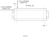
- FIG. 2 shows a photographing region of interest of a pouch-type battery cell and an inspection direction along an x axis/y axis, according to an embodiment.
- an overhang where a negative electrode protrudes relative to a positive electrode is observed in a corner portion, such that the corner portion may be set as regions of interest ROI 1 and ROI 2.
- another portion where an overhang may be observed may be set as a region of interest to obtain an electrode image.
- the electrode images of the battery cells C1 and C2 obtained by the photographing unit 200 may be delivered to the inspection unit 300.
- the inspection unit 300 may include a memory 310 that stores a learning model trained to track an electrode endpoint in an electrode image of a battery cell and a controller 320 that determines whether an electrode is defective by using the learning model.
- the memory 310 may be various storage media such as a semiconductor memory like random-access memory (RAM), read-only memory (ROM), flash memory, etc., and a magnetic disk, an optical disk, etc.
- the learning model stored in the memory 310 is an artificial intelligence machine learning model trained to track an electrode endpoint in an electrode image of a battery cell, and may be, for example, a deep learning model having a multi-layer artificial neural network structure.
- a process of generating and training a learning model is as described below.
- Learning data including an electrode image of a battery cell may be input, and the learning data may be labelled as a learning base task for tracking an electrode endpoint.
- Labelling may refer to a process of inputting various information serving purposes to enable artificial intelligence to learn data such as images, video, texts, etc., into each data.
- Each labelled data may be stored as points to constitute learning data.
- a feature may be extracted based on the labelled learning data, and a database in which the feature is recorded may be structured to match the feature to a feature of input data, thereby generating a learning model.
- the learning model may undergo a process of receiving a battery cell electrode image as input data and extracting a feature of each input data for comparison, and matching the extracted feature to a feature of a previously generated database to optimize a shape of an object having a high matching rate.
- the controller 320 may track an electrode endpoint in an electrode image of a battery cell by using the learning model stored in the memory 310 and determine whether an electrode of the battery cell is defective, based on coordinate information of the electrode endpoint.
- the controller 320 may include a processor that processes data and performs an operation, such as a CPU, an MPU, an MCU, etc.
- An example electrode endpoint tracking process using the learning model is as described below.
- a preprocessing process of input image data may be performed.
- an input image may be converted into a high-quality image by using a deep learning-based high-resolution algorithm.
- the high-quality image may be segmented to detect endpoints of a negative electrode and a positive electrode.
- a skeleton model may be extracted from the shape of the endpoint detected through segmentation, and disconnected and connected portions may be post-processed to extract contour information.
- the controller 320 may track coordinates of the electrode endpoint in the input image and determine whether the electrode is defective, based on the coordinate information.
- the battery cell inspection system may perform inspection based on a 3D image obtained by photographing the electrode of the battery cell.
- the transferring unit 110 may rotate a tray on which inspection target battery cells are loaded, by 360 degrees with respect to an axis in the photographing point, and the photographing unit 210 may generate a 3D image based on a tomographic image captured during rotation of the tray and the battery cells.
- a computed tomography (CT) technique may be used as a 3D imaging scheme, in which a tomographic image may be obtained by transmitting X rays while rotating a battery cell, and a 3D image may be obtained by reconstructing multiple tomographic images.
- CT computed tomography
- the controller 320 may generate cross-sectional images for two or more directions (e.g., an x-axis direction cross-sectional image and a y-axis direction cross-sectional image) based on the 3D image, and track an electrode endpoint for each cross-sectional image by using a learning model.
- the learning model may be trained by using, as learning data, the cross-sectional images for the two or more directions (e.g., the x-axis direction and the y-axis direction) generated based on a 3D image.
- FIG. 3A shows a 2D image of a battery cell internal electrode, obtained through radiography
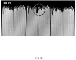
- FIG. 3B shows a cross-sectional image generated based on a 3D image of a battery cell internal electrode, obtained through radiography.
- the electrode is not clearly distinguished due to low resolution, making it difficult to track the electrode endpoint.
- a high-resolution cross-sectional image may be obtained as shown in FIG. 3B , and the accuracy of endpoint tracking may be improved through cross-sectional inspection for the two or more directions (e.g., the x-axis direction and the y-axis direction).
- the controller 320 may determine whether an electrode is defective, by using electrode tracking coordinates. According to an embodiment, in at least one of a case where some positive electrode or negative electrode is bent, a case where some positive electrode or negative electrode is missing, a case where a gap between endpoints of adjacent positive electrode and negative electrode is equal to or greater than a reference value, a case where an insertion order of a positive electrode or a negative electrode is reversed, a case where a gap between endpoints of adjacent positive electrodes or a gap between endpoints of adjacent negative electrodes is equal to or greater than a reference value, a case where a parameter indicating an alignment state of a positive electrode and a negative electrode in a specific section is equal to or less than a reference value, and a case where some positive electrode or negative electrode is disconnected, the controller 320 may determine that an electrode of the battery cell is defective.
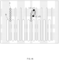
- FIGS. 4A to 4G are schematic diagrams of an electrode cross-sectional image of a battery cell, respectively showing cases where an electrode may be determined to be defective.
- FIG. 4A shows a case where some negative electrode A is bent in an electrode structure where the negative electrode A and a positive electrode B are alternately stacked.
- the controller 320 may track endpoint coordinates (x1, y1) and (x2, y2) of a negative electrode by using a learning model, and calculate how much the negative electrode A is bent, based on coordinate information. For example, when endpoint coordinates of a negative electrode satisfy the following equation, it may be determined that excessive deformation occurs in the negative electrode.
- reference values X ref and Y ref for determining a defect may be set arbitrarily. x 1 ⁇ x 2 > X ref or y 1 ⁇ y 2 > Y ref
- a negative electrode when tracked points along a negative electrode are sequentially aligned for each position, a negative electrode may be estimated as being bent for the greatest value y of intermediate coordinates. As such, when the negative electrode is bent, a circuit may be short-circuited due to contact with another electrode, such that the corresponding battery cell may be determined to be defective.
- FIG. 4B shows a case where some positive electrode B' is missing in an electrode structure where the negative electrode A and the positive electrode B are alternately stacked.
- the controller 320 may inspect the number of positive electrode and negative electrode stacks by tracking an electrode endpoint, in which when the inspected number of stacks is not equal to a designated number, the controller 320 may determine that some electrode is missing. In this case, the circuit may be short-circuited due to contact between negative electrodes or positive electrodes, such that the controller 320 may determine that the corresponding battery cell is defective.
- FIG. 4C shows a case where a gap between endpoints of the adjacent negative electrode A and positive electrode B is equal to or greater than a reference value in an electrode structure where the negative electrode A and the positive electrode B are alternately stacked.
- the controller 320 may track negative electrode endpoint coordinates (x1, y1) and (x3, y3) and positive electrode endpoint coordinates (x2, y2) by using the learning model, and measure a size of a gap between electrodes based on coordinate information.
- the size of the gap is equal to or greater than a reference value, a circuit is likely to be short-circuited due to bending of an electrode and contact between electrodes, such that the controller 320 may determine that the corresponding battery cell is defective.
- FIG. 4D shows a case where an insertion order of a positive electrode or a negative electrode is reversed in a structure where a negative electrode and a positive electrode are stacked alternately.
- Positive electrodes have to be inserted at positions A and A' and negative electrodes have to be inserted at a position B in a normal case, but when a negative electrode is inserted in place of a positive electrode and a positive electrode is inserted in place of a negative electrode as shown in FIG. 4D , a corresponding battery cell may be determined to be defective.
- the controller 320 may track endpoint coordinates (x1, y1), (x2, y2), and (x3, y3) of three consecutive electrodes according to a Bi-cell sequence, compare heights (y1, y2, y3) of the respective end points, and determine that a corresponding cell is defective due to fault insertion of the Bi-cell when y1 and y3 are higher than y2.
- a corresponding cell may be determined to be defective.
- FIG. 4E shows a case where a gap between endpoints of adjacent electrodes is equal to or greater than a reference value due to introduction of a foreign substance (e.g., a tape, a scrap, etc.) between a positive electrode/a negative electrode or folding of a separator, in a structure where the negative electrode and the positive electrode are stacked alternately.
- the controller 320 may determine that a defect occurs when the following equation is satisfied for end point coordinates (xn, yn) of a positive electrode or a negative electrode.
- a reference value X ref may be set at random. x n + 1 ⁇ x n > X ref
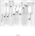
- FIG. 4F shows a case where a parameter indicating an alignment state of a positive electrode and a negative electrode in a specific section is less than or equal to a reference value.
- the controller 320 may set temporary lines indicating alignment criteria for a positive electrode and a negative electrode and set a difference from the temporary lines as a parameter for each positive electrode/negative electrode. For example, when the temporary line for a positive electrode or a negative electrode is set as AVG, the controller 320 may determine that a defect occurs when the following equation is satisfied for end point coordinates (xn, yn) of a positive electrode or a negative electrode.
- the reference value Y ref may be set for each positive electrode/negative electrode. y n ⁇ AVG > Y ref
- FIG. 4G shows a case where some positive electrode or negative electrode is disconnected.
- A indicates a case where an electrode is fully disconnected and B indicates an electrode is partially disconnected.
- the controller 320 determines that an electrode is fully disconnected when an electrode length tracked from an electrode bottom is shorter than that of an adjacent electrode, and determines that an electrode is partially disconnected when tracking is interrupted around a tab. When the tab is disconnected in this way, safety is degraded, determining that a battery cell is defective.
- the controller 320 may determine whether an electrode is defective based on a rule-based algorithm together with an artificial intelligence learning model or separately.
- a user determines a defect for an input electrode image according to a predetermined rule.
- This scheme may automatically determine a defect without a separate machine learning process, but the accuracy thereof may be degraded due to a non-uniform shape of the electrode of the battery cell.
- FIG. 5 shows arrangement structures and a tray and a battery cell to simultaneously inspect multiple battery cells.
- the transferring unit 110 may simultaneously transfer the two or more trays 101 and 102 to the photographing point.
- the two or more battery cells C1 and C2 may be respectively loaded on the trays 101 and 102.
- the trays 101 and 102 transferred from the photographing point may be arranged to allow radiation output from the radiation source 210 to penetrate the regions of interest R1 and R2 of the battery cells C1 and C2 loaded on all the trays 101 and 102.
- corners of the battery cells C1 loaded on the tray 101 may face corners of the battery cells C2 loaded on another tray 102.
- Radiation penetrating the regions of interest R1 and R2 of the battery cells may be detected by the radiation detector 220, and the inspection unit 200 may obtain electrode images for the multiple battery cells C1 and C2 by using the information. As such, by simultaneously inspecting several battery cells, a time required for inspection may be greatly reduced.
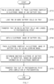
- FIG. 6 is a flowchart showing a battery cell inspection method according to an embodiment.
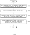
- operation S610 of training a learning model to track an electrode endpoint in an electrode image of a battery cell may be performed.
- the learning model may be generated and trained using a segment labelling scheme. A process of generating and training the learning model is described and thus will not be described in detail.
- the learning model may be stored in the memory 310 of the inspection unit 300.
- operation S620 of obtaining the electrode image of the battery cell may be performed.
- Operation S620 may be performed by the photographing unit 200 including the radiation source 210 that outputs radiation (e.g., X rays) toward a region of interest (ROI) of the battery cell and the radiation detector 220 that detects radiation penetrating the region of interest, as shown in FIG. 1 .
- operation S620 may include an operation of outputting radiation toward a region of interest of the battery cell by using the radiation source 210 and an operation of detecting radiation penetrating the region of interest of the battery cell by using the radiation detector 220.
- operation S630 of tracking an electrode endpoint in the electrode image of the battery cell by using the learning model may be performed.
- Operation S630 may be performed by the controller 320 included in the inspection unit 300.
- the controller 320 may generate cross-sectional images for two or more directions (e.g., an x-axis direction cross-sectional image and a y-axis direction cross-sectional image) based on the 3D image, and track an electrode endpoint for each cross-sectional image by using a learning model trained based on three-dimensional image data.
- operation S640 of determining whether an electrode of the battery cell is defective, based on coordinate information of the electrode endpoint may be performed. Operation S640 may be performed by the controller 320.
- the electrode of the battery cell may be determined to be defective in at least one of a case where some positive electrode or negative electrode is bent, a case where some positive electrode or negative electrode is missing, a case where a gap between endpoints of adjacent positive electrode and negative electrode is equal to or greater than a reference value, a case where an insertion order of a positive electrode or a negative electrode is reversed, a case where a gap between endpoints of adjacent positive electrodes or a gap between endpoints of adjacent negative electrodes is equal to or greater than a reference value, a case where a parameter indicating an alignment state of a positive electrode and a negative electrode in a specific section is equal to or less than a reference value, and a case where some positive electrode or negative electrode is disconnected (see FIGS. 4A to 4G ).
- FIG. 7 is a flowchart showing a battery cell inspection method according to another embodiment.
- operation S710 of training a learning model to track an electrode endpoint in an electrode image of a battery cell may be performed.
- Operation S710 is substantially the same as operation S610 described with reference to FIG. 6 , and thus will not be described in detail.
- operation S720 of loading two or more battery cells on a tray and operation S730 of transferring the tray on which the battery cells are loaded, to a photographing point may be performed.
- the two or more battery cells C1 and C2 may be respectively loaded on the trays 101 and 102.
- the battery cells may be loaded exactly on top of each other.
- operation S740 of obtaining the electrode image of the battery cell operation S750 of tracking an electrode endpoint in the electrode image of the battery cell by using the learning model, and operation S760 of determining whether the electrode of the battery cell is defective based on coordinate information of the electrode endpoint may be sequentially performed.
- Operations S740 to S760 are substantially the same as operations S620 to S640 described with reference to FIG. 6 , and thus will not be described in detail.
- operation S770 of transferring the tray out of the photographing point may be performed. Operation S770 may be performed at any point in time after operation S740 of obtaining the image of the electrode is finished. Operations S730 and S770 of transferring the battery cell and the tray may be performed by the transferring unit 110 (see FIG. 1 ).
- an operation of rotating, by the transferring unit 110, the tray on which the battery cells are loaded with respect to an axis in the photographing point may be further performed, and in this case, the photographing unit 200 may further perform an operation of obtaining the three-dimensional image of the battery cell based on the two-dimensional radiographic image obtained during rotation of the tray.
- At least some operation of the battery cell inspection method according to the embodiments may be implemented in the form of an application or a program instruction that is executable through various computer components and recorded in a computer-readable recording medium.
- the computer-readable recording medium may include a program instruction, a data file, a data structure and the like solely or in combination.
- an electrode endpoint may be tracked in a battery cell image by using an artificial intelligence learning model and whether an electrode is defective may be automatically determined based thereon. Moreover, by simultaneously obtaining electrode images of several stacked battery cells and automatically inspecting an electrode of each battery cell by using a learning model, a time required for inspection may be largely reduced. Thus, unlike existing sampling inspection, total inspection may be possible and thus a risk corresponding to a defect of a product may be greatly reduced.
Landscapes
- Engineering & Computer Science (AREA)
- Physics & Mathematics (AREA)
- Theoretical Computer Science (AREA)
- General Physics & Mathematics (AREA)
- Health & Medical Sciences (AREA)
- Life Sciences & Earth Sciences (AREA)
- Chemical & Material Sciences (AREA)
- General Health & Medical Sciences (AREA)
- Computer Vision & Pattern Recognition (AREA)
- Biophysics (AREA)
- Biomedical Technology (AREA)
- Immunology (AREA)
- Biochemistry (AREA)
- Pathology (AREA)
- Analytical Chemistry (AREA)
- Electrochemistry (AREA)
- General Chemical & Material Sciences (AREA)
- Manufacturing & Machinery (AREA)
- Chemical Kinetics & Catalysis (AREA)
- Computing Systems (AREA)
- Data Mining & Analysis (AREA)
- Computational Linguistics (AREA)
- General Engineering & Computer Science (AREA)
- Mathematical Physics (AREA)
- Software Systems (AREA)
- Quality & Reliability (AREA)
- Artificial Intelligence (AREA)
- Evolutionary Computation (AREA)
- Molecular Biology (AREA)
- Neurology (AREA)
- Nuclear Medicine, Radiotherapy & Molecular Imaging (AREA)
- Pulmonology (AREA)
- Radiology & Medical Imaging (AREA)
- Analysing Materials By The Use Of Radiation (AREA)
- Secondary Cells (AREA)
- Image Analysis (AREA)
Abstract
Description
- This application claims priority to and the benefit of
Korean Patent Application No. 10-2021-0185151 filed in the Korean Intellectual Property Office on December 22, 2021 - Embodiments disclosed herein relate to a battery cell inspection system and method.
- With the recent rapid development of electrical, electronics, communication, and computer industries, the demand for high-performance and high-safety batteries is gradually increasing. A lithium polymer battery, a type of secondary batteries, is a battery capable of repeating charge and discharge through reversible interconversion between chemical energy and electrical energy, and has been used variously for portable electronic devices, electric vehicle batteries, etc., due to the advantages of long life and large capacity.
- Generally, an electrode assembly of a lithium polymer battery has a structure in which a plurality of positive electrodes and negative electrodes are alternately stacked with separators therebetween. To prevent the precipitation of lithium, the negative electrode may have a large area enough to cover the positive electrode, in which a protruding portion of the negative electrode is referred to as an overhang. When an overhang portion is bent or protrudes too much, or some electrode is missing due to a problem in a manufacturing process, it may lead to a defect of a battery and thus require a process of inspecting an electrode through internal CT scan. However, in an existing battery cell inspection system, an inspector observes an image of an inspection object with the naked eyes to determine a defect, making it difficult to perform total inspection due to a long time taken and resulting in a limitation in reducing a defect rate merely with sampling inspection.
- Embodiments disclosed herein aim to a battery cell inspection system and method in which an electrode endpoint is tracked in a battery cell image using an artificial intelligence learning model and it is automatically determined based thereon whether an electrode is defective.
- Technical problems of the embodiments disclosed herein are not limited to the above-described technical problems, and other unmentioned technical problems would be clearly understood by one of ordinary skill in the art from the following description.
- A battery cell inspection system according to an embodiment includes a photographing unit configured to obtain an electrode image of a battery cell, a memory storing a learning model trained to track an electrode endpoint in an electrode image of a battery cell, and a controller configured to track the electrode endpoint in the electrode image of the battery cell by using the learning model, and determine whether an electrode of the battery cell is defective, based on coordinate information of the electrode endpoint.
- In the battery cell inspection system according to an embodiment, the learning model may be generated by receiving learning data including an electrode image of a battery cell, labelling the learning data, extracting a feature based on the labelled learning data, and developing a database where the feature is recorded.
- In the battery cell inspection system according to an embodiment, the photographing unit may include a radiation source configured to output radiation toward a region of interest of the battery cell and a radiation detector configured to detect radiation penetrating the region of interest of the battery cell.
- In the battery cell inspection system according to an embodiment, the photographing unit may be further configured to obtain a three-dimensional image for the region of interest of the battery cell, and the controller may be further configured to generate cross-sectional images for two or more directions based on the three-dimensional image and track an electrode endpoint of the battery cell for each of the cross-sectional images, and the learning model may be trained using cross-sectional images for two or more directions, generated based on a three-dimensional image, as learning data.
- In the battery cell inspection system according to an embodiment, an electrode of the battery cell may include a structure where a plurality of positive electrodes and a plurality of negative electrodes are alternately stacked with separators therebetween, and the controller may be further configured to determine that the electrode of the battery cell is defective, in at least one of a case where some positive electrode or negative electrode is bent, a case where some positive electrode or negative electrode is missing, a case where a gap between endpoints of adjacent positive electrode and negative electrode is equal to or greater than a reference value, a case where an insertion order of a positive electrode or a negative electrode is reversed, a case where a gap between endpoints of adjacent positive electrodes or a gap between endpoints of adjacent negative electrodes is equal to or greater than a reference value, a case where a parameter indicating an alignment state of a positive electrode and a negative electrode in a specific section is equal to or less than a reference value, and a case where some positive electrode or negative electrode is disconnected.
- The battery cell inspection system according to an embodiment may further include a tray on which two or more battery cells are loaded and a transferring unit configured to transfer the tray on which the battery cells are loaded, to a photographing point of the photographing unit, and transfer the tray out of the photographing point upon completion of photographing.
- In the battery cell inspection system according to an embodiment, the transferring unit may be further configured to simultaneously transfer two or more trays on which the battery cells are loaded, to the photographing point, and the two or more trays may be arranged such that the radiation output from the radiation source penetrates regions of interest of the battery cells loaded on all of the trays at the same time.
- In the battery cell inspection system according to an embodiment, the two or more trays may be arranged such that corners of the battery cells loaded on each tray face corners of the battery cells loaded on another tray, in the photographing point.
- In the battery cell inspection system according to an embodiment, the transferring unit may be further configured to rotate the tray on which the battery cells are loaded, with respect to an axis in the photographing point, and the photographing unit may be further configured to obtain a three-dimensional image of the battery cell based on a two-dimensional radiation image obtained during rotation of the tray.
- A battery cell inspection method according to an embodiment may include training a learning model to track an electrode endpoint in an electrode image of a battery cell, obtaining the electrode image of the battery cell, tracking the electrode endpoint in the electrode image of the battery cell by using the learning model, and determining whether an electrode of the battery cell is defective, based on coordinate information of the electrode endpoint.
- In the battery cell inspection method according to an embodiment, the learning model may be generated by receiving learning data including an electrode image of a battery cell, labelling the learning data, extracting a feature based on the labelled learning data, and developing a database where the feature is recorded.
- In the battery cell inspection method according to an embodiment, the obtaining of the electrode image of the battery cell may include outputting radiation toward a region of interest of the battery cell and detecting radiation penetrating the region of interest of the battery cell.
- In the battery cell inspection method according to an embodiment, the obtaining of the electrode image of the battery cell may include obtaining a three-dimensional image for the region of interest of the battery cell, and the tracking of the electrode endpoint of the battery cell may include generating cross-sectional images for two or more directions based on the three-dimensional image and tracking the electrode endpoint of the battery cell for each of the cross-sectional images, and the learning model may be trained using cross-sectional images for two or more directions, generated based on a three-dimensional image, as learning data.
- In the battery cell inspection method according to an embodiment, an electrode of the battery cell may include a structure where a plurality of positive electrodes and a plurality of negative electrodes are alternately stacked with a separator therebetween, and the battery cell inspection method may further include determining that the electrode of the battery cell is defective, in at least one of a case where some positive electrode or negative electrode is bent, a case where some positive electrode or negative electrode is missing, a case where a gap between endpoints of adjacent positive electrode and negative electrode is equal to or greater than a reference value, a case where an insertion order of a positive electrode or a negative electrode is reversed, a case where a gap between endpoints of adjacent positive electrodes or a gap between endpoints of adjacent negative electrodes is equal to or greater than a reference value, a case where a parameter indicating an alignment state of a positive electrode and a negative electrode in a specific section is equal to or less than a reference value, and a case where some positive electrode or negative electrode is disconnected.
- The battery cell inspection method may further include loading two or more battery cells on a tray, transferring the tray on which the battery cells are loaded, to a photographing point, and transferring the tray out of the photographing point upon completion of photographing.
- In the battery cell inspection method according to an embodiment, the transferring of the tray to the photographing point may include simultaneously transferring two or more trays on which the battery cells are loaded, to the photographing point, and the two or more trays may be arranged such that the radiation penetrates regions of interest of the battery cells loaded on all of the trays at the same time.
- In the battery cell inspection method according to an embodiment, the two or more trays may be arranged such that corners of the battery cells loaded on each tray face corners of the battery cells loaded on another tray, in the photographing point.
- The battery cell inspection method according to an embodiment may further include rotating the tray on which the battery cells are loaded, with respect to an axis in the photographing point, in which the obtaining of the electrode image of the battery cell may include obtaining a three-dimensional image of the battery cell based on a two-dimensional radiation image obtained during rotation of the tray.
- Embodiments disclosed herein aim to describe a battery cell inspection system and method in which an electrode endpoint may be tracked in a battery cell image using an artificial intelligence learning model and a defect of an electrode may be automatically determined based on the tracked electrode endpoint.
- According to the proposed system and method, by simultaneously obtaining electrode images of several stacked battery cells and automatically inspecting an electrode of each battery cell by using a learning model, a time required for inspection may be largely reduced. Thus, unlike existing sampling inspection, total inspection may be possible and thus a risk corresponding to a defect of a product may be greatly reduced.
- Moreover, various effects recognized directly or indirectly from the disclosure may be provided.
- In order to more clearly describe technical solutions of embodiments disclosed herein or the prior art, the drawings required in the description of the embodiments are briefly introduced below. It should be understood that the following drawings are for the purpose of explaining the embodiments of the present specification and not for limiting purposes. In addition, representations of some components in the drawings may be exaggerated or omitted for clarity of explanation.
-
FIG. 1 shows a configuring and operating process of a battery cell inspection system according to an embodiment. -
FIG. 2 shows a photographing region-of-interest of a battery cell and an inspection direction along an x axis/y axis, according to an embodiment. -
FIG. 3A shows a two-dimensional (2D) image, obtained through X-ray photography, of an internal electrode of a battery cell. -
FIG. 3B shows a cross-sectional image generated based on a three-dimensional (3D) image, obtained through X-ray photography, of an internal electrode of a battery cell. -
FIGS. 4A to 4G illustrate a case where each battery cell electrode is determined to be defective. -
FIG. 5 shows arrangement structures of a tray and a battery cell to simultaneously inspect multiple battery cells. -
FIG. 6 is a flowchart showing a battery cell inspection method according to an embodiment. -
FIG. 7 is a flowchart showing a battery cell inspection method according to another embodiment. - Hereinafter, embodiments disclosed in this document will be described in detail with reference to the exemplary drawings. In adding reference numerals to components of each drawing, it should be noted that the same components are given the same reference numerals even though they are indicated in different drawings. In addition, in describing the embodiments disclosed in this document, when it is determined that a detailed description of a related known configuration or function interferes with the understanding of an embodiment disclosed in this document, the detailed description thereof will be omitted.
- Although terms used herein are selected with general terms popularly used at present under the consideration of functions in the disclosure, the terms may vary according to the intention of those of ordinary skill in the art, custom, or introduction of new technology. In addition, in a specific case, the applicant voluntarily may select terms, and in this case, the meaning of the terms may be disclosed in a corresponding description part of the present specification. Therefore, the terms used herein should be defined not by the simple names of the terms but by the substantial meaning of the terms and the contents throughout the disclosure. Moreover, terms defined in the present disclosure are used for only describing a specific exemplary embodiment and may not have an intention to limit the scope of other exemplary embodiments. It is to be understood that the singular forms include plural references unless the context clearly dictates otherwise.
-
FIG. 1 shows a configuring and operating process of a battery cell inspection system according to an embodiment. Referring toFIG. 1 , a battery cell inspection system according to an embodiment may includetrays unit 110 for transferring thetrays unit 200 for obtaining electrode images of the battery cells C1 and C2, and aninspection unit 300 for tracking electrode endpoints of the battery cells C1 and C2 and determining whether electrodes are defective based thereon. - A battery cell is a minimum unit constituting a rechargeable secondary battery, and may be manufactured through a process of packaging an electrode assembly, an activating process of activating a battery by charging and discharging the battery having passed through the packaging process, a degassing process of discharging a gas from a battery cell, and a folding process of cutting a part of a pouch and sealing the pouch.
- The electrode assembly may be manufactured through a notching process of making positive electrode and negative electrode tabs of the battery, a stacking process of stacking a battery material, and a tab welding process of welding the positive electrode and negative electrode tabs. A general electrode structure has a structure in which a single positive electrode sheet or a plurality of positive electrode sheets where a positive electrode active material is formed on a positive electrode current collector and a single negative electrode sheet or a plurality of negative electrode sheets where a positive electrode active material is formed on a negative electrode current collector are alternately stacked, and the positive electrode sheet and the negative electrode sheet may face each other with a separator sheet therebetween. In this case, to prevent the precipitation of lithium, the negative electrode may have a large area enough to cover the positive electrode, in which when the protruding portion of the negative electrode is bent, a gap with the positive electrode is too large, or some electrode is missing, it may lead to a defect of the battery cell and thus it is determined through a separate inspection process whether the electrode is defective.
- The two or more battery cells C1 and C2 may be respectively loaded on the
trays trays - The transferring
unit 110 may transfer thetrays trays unit 110 may transfer thetrays trays unit 110 may be a conveyor belt for carrying thetrays unit 110 may carry thetrays trays - The photographing
unit 200 may photograph regions of interest (ROI) of the battery cells C1 and C2, transferred by the transferringunit 110, to obtain electrode images. Herein, the region of interest may be a corner portion where an electrode of each battery cell is located. According to an embodiment, the photographingunit 200 may include aradiation source 210 that outputs radiation toward a region of interest of the battery cell and aradiation detector 220 that detects radiation having penetrated the region of interest. - The
radiation source 210 may be an X-ray tube having a capacity of about 160 to about 240 kV. The X-ray tube may be, for example, a hot-cathode x-ray tube that emits X rays by colliding with a material after creating an electron beam moving at high speed using a heated tungsten filament. - The
radiation detector 220 may detect X rays and reconstruct an image by using X-ray information. As shown inFIG. 1 , theradiation detector 220 may be located on the opposite side of theradiation source 210 with respect to an inspection target battery cell to detect X rays penetrating the region of interest of the battery cell and reconstruct them as an image. - The battery cells C1 and C2 may be transferred to a photographing point located between the
radiation source 210 and the radiation detector 220 (i.e., a position where radiation emitted from theradiation source 210 passes a corner electrode portion of the battery cell). According to an embodiment, to locate the battery cells C1 and C2 at an exact photographing point, the position of the transferringunit 110 coupled to thetrays trays unit 110 may be fixed, and the position of theradiation source 210 may be manually or automatically fine-adjusted. -
FIG. 2 shows a photographing region of interest of a pouch-type battery cell and an inspection direction along an x axis/y axis, according to an embodiment. For the pouch-type battery cell, an overhang where a negative electrode protrudes relative to a positive electrode is observed in a corner portion, such that the corner portion may be set as regions ofinterest ROI 1 andROI 2. Although not shown, for a prismatic battery cell or cylindrical battery cell, another portion where an overhang may be observed may be set as a region of interest to obtain an electrode image. - The electrode images of the battery cells C1 and C2 obtained by the photographing
unit 200 may be delivered to theinspection unit 300. Referring toFIG. 1 , theinspection unit 300 may include amemory 310 that stores a learning model trained to track an electrode endpoint in an electrode image of a battery cell and acontroller 320 that determines whether an electrode is defective by using the learning model. - The
memory 310 may be various storage media such as a semiconductor memory like random-access memory (RAM), read-only memory (ROM), flash memory, etc., and a magnetic disk, an optical disk, etc. The learning model stored in thememory 310 is an artificial intelligence machine learning model trained to track an electrode endpoint in an electrode image of a battery cell, and may be, for example, a deep learning model having a multi-layer artificial neural network structure. - A process of generating and training a learning model according to an embodiment is as described below. Learning data including an electrode image of a battery cell may be input, and the learning data may be labelled as a learning base task for tracking an electrode endpoint. Labelling may refer to a process of inputting various information serving purposes to enable artificial intelligence to learn data such as images, video, texts, etc., into each data. Each labelled data may be stored as points to constitute learning data. A feature may be extracted based on the labelled learning data, and a database in which the feature is recorded may be structured to match the feature to a feature of input data, thereby generating a learning model. The learning model may undergo a process of receiving a battery cell electrode image as input data and extracting a feature of each input data for comparison, and matching the extracted feature to a feature of a previously generated database to optimize a shape of an object having a high matching rate.
- The
controller 320 may track an electrode endpoint in an electrode image of a battery cell by using the learning model stored in thememory 310 and determine whether an electrode of the battery cell is defective, based on coordinate information of the electrode endpoint. Thecontroller 320 may include a processor that processes data and performs an operation, such as a CPU, an MPU, an MCU, etc. - An example electrode endpoint tracking process using the learning model is as described below. First, a preprocessing process of input image data may be performed. For example, an input image may be converted into a high-quality image by using a deep learning-based high-resolution algorithm. Next, in a shape detection stage, the high-quality image may be segmented to detect endpoints of a negative electrode and a positive electrode. Next, a skeleton model may be extracted from the shape of the endpoint detected through segmentation, and disconnected and connected portions may be post-processed to extract contour information. Through such a series of processes, the
controller 320 may track coordinates of the electrode endpoint in the input image and determine whether the electrode is defective, based on the coordinate information. - According to an embodiment, the battery cell inspection system may perform inspection based on a 3D image obtained by photographing the electrode of the battery cell. According to an embodiment, the transferring
unit 110 may rotate a tray on which inspection target battery cells are loaded, by 360 degrees with respect to an axis in the photographing point, and the photographingunit 210 may generate a 3D image based on a tomographic image captured during rotation of the tray and the battery cells. A computed tomography (CT) technique may be used as a 3D imaging scheme, in which a tomographic image may be obtained by transmitting X rays while rotating a battery cell, and a 3D image may be obtained by reconstructing multiple tomographic images. - According to an embodiment, the
controller 320 may generate cross-sectional images for two or more directions (e.g., an x-axis direction cross-sectional image and a y-axis direction cross-sectional image) based on the 3D image, and track an electrode endpoint for each cross-sectional image by using a learning model. The learning model may be trained by using, as learning data, the cross-sectional images for the two or more directions (e.g., the x-axis direction and the y-axis direction) generated based on a 3D image. -
FIG. 3A shows a 2D image of a battery cell internal electrode, obtained through radiography, andFIG. 3B shows a cross-sectional image generated based on a 3D image of a battery cell internal electrode, obtained through radiography. For the 2D image shown inFIG. 3A , the electrode is not clearly distinguished due to low resolution, making it difficult to track the electrode endpoint. On the other hand, by obtaining the 3D image, a high-resolution cross-sectional image may be obtained as shown inFIG. 3B , and the accuracy of endpoint tracking may be improved through cross-sectional inspection for the two or more directions (e.g., the x-axis direction and the y-axis direction). - The
controller 320 may determine whether an electrode is defective, by using electrode tracking coordinates. According to an embodiment, in at least one of a case where some positive electrode or negative electrode is bent, a case where some positive electrode or negative electrode is missing, a case where a gap between endpoints of adjacent positive electrode and negative electrode is equal to or greater than a reference value, a case where an insertion order of a positive electrode or a negative electrode is reversed, a case where a gap between endpoints of adjacent positive electrodes or a gap between endpoints of adjacent negative electrodes is equal to or greater than a reference value, a case where a parameter indicating an alignment state of a positive electrode and a negative electrode in a specific section is equal to or less than a reference value, and a case where some positive electrode or negative electrode is disconnected, thecontroller 320 may determine that an electrode of the battery cell is defective. -
FIGS. 4A to 4G are schematic diagrams of an electrode cross-sectional image of a battery cell, respectively showing cases where an electrode may be determined to be defective. -
FIG. 4A shows a case where some negative electrode A is bent in an electrode structure where the negative electrode A and a positive electrode B are alternately stacked. Thecontroller 320 may track endpoint coordinates (x1, y1) and (x2, y2) of a negative electrode by using a learning model, and calculate how much the negative electrode A is bent, based on coordinate information. For example, when endpoint coordinates of a negative electrode satisfy the following equation, it may be determined that excessive deformation occurs in the negative electrode. Herein, reference values Xref and Yref for determining a defect may be set arbitrarily.
- Alternatively, when tracked points along a negative electrode are sequentially aligned for each position, a negative electrode may be estimated as being bent for the greatest value y of intermediate coordinates. As such, when the negative electrode is bent, a circuit may be short-circuited due to contact with another electrode, such that the corresponding battery cell may be determined to be defective.
-
FIG. 4B shows a case where some positive electrode B' is missing in an electrode structure where the negative electrode A and the positive electrode B are alternately stacked. Thecontroller 320 may inspect the number of positive electrode and negative electrode stacks by tracking an electrode endpoint, in which when the inspected number of stacks is not equal to a designated number, thecontroller 320 may determine that some electrode is missing. In this case, the circuit may be short-circuited due to contact between negative electrodes or positive electrodes, such that thecontroller 320 may determine that the corresponding battery cell is defective. -
FIG. 4C shows a case where a gap between endpoints of the adjacent negative electrode A and positive electrode B is equal to or greater than a reference value in an electrode structure where the negative electrode A and the positive electrode B are alternately stacked. Thecontroller 320 may track negative electrode endpoint coordinates (x1, y1) and (x3, y3) and positive electrode endpoint coordinates (x2, y2) by using the learning model, and measure a size of a gap between electrodes based on coordinate information. When the size of the gap is equal to or greater than a reference value, a circuit is likely to be short-circuited due to bending of an electrode and contact between electrodes, such that thecontroller 320 may determine that the corresponding battery cell is defective. -
FIG. 4D shows a case where an insertion order of a positive electrode or a negative electrode is reversed in a structure where a negative electrode and a positive electrode are stacked alternately. Positive electrodes have to be inserted at positions A and A' and negative electrodes have to be inserted at a position B in a normal case, but when a negative electrode is inserted in place of a positive electrode and a positive electrode is inserted in place of a negative electrode as shown inFIG. 4D , a corresponding battery cell may be determined to be defective. For example, thecontroller 320 may track endpoint coordinates (x1, y1), (x2, y2), and (x3, y3) of three consecutive electrodes according to a Bi-cell sequence, compare heights (y1, y2, y3) of the respective end points, and determine that a corresponding cell is defective due to fault insertion of the Bi-cell when y1 and y3 are higher than y2. Alternatively, as a result of tracking a height of each electrode, when high electrodes are consecutive or low electrodes are consecutive without repetition of the high electrodes and the low electrodes, a corresponding cell may be determined to be defective. -
FIG. 4E shows a case where a gap between endpoints of adjacent electrodes is equal to or greater than a reference value due to introduction of a foreign substance (e.g., a tape, a scrap, etc.) between a positive electrode/a negative electrode or folding of a separator, in a structure where the negative electrode and the positive electrode are stacked alternately. For example, thecontroller 320 may determine that a defect occurs when the following equation is satisfied for end point coordinates (xn, yn) of a positive electrode or a negative electrode. Herein, a reference value Xref may be set at random.
-
FIG. 4F shows a case where a parameter indicating an alignment state of a positive electrode and a negative electrode in a specific section is less than or equal to a reference value. This is a case where an AC overhang does not occur, but high variability occurs due to a poor alignment state of the positive electrode and the negative electrode. In this case, thecontroller 320 may set temporary lines indicating alignment criteria for a positive electrode and a negative electrode and set a difference from the temporary lines as a parameter for each positive electrode/negative electrode. For example, when the temporary line for a positive electrode or a negative electrode is set as AVG, thecontroller 320 may determine that a defect occurs when the following equation is satisfied for end point coordinates (xn, yn) of a positive electrode or a negative electrode. Herein, the reference value Yref may be set for each positive electrode/negative electrode.
-
FIG. 4G shows a case where some positive electrode or negative electrode is disconnected. Referring toFIG. 4G , A indicates a case where an electrode is fully disconnected and B indicates an electrode is partially disconnected. Thecontroller 320 determines that an electrode is fully disconnected when an electrode length tracked from an electrode bottom is shorter than that of an adjacent electrode, and determines that an electrode is partially disconnected when tracking is interrupted around a tab. When the tab is disconnected in this way, safety is degraded, determining that a battery cell is defective. - While a description has been made of a case where an electrode defect is determined, with reference to
FIGS. 4A to 4G , this is merely an example and various cases for determining a defect based on electrode endpoint coordinates may be added as embodiments. - According to an embodiment, the
controller 320 may determine whether an electrode is defective based on a rule-based algorithm together with an artificial intelligence learning model or separately. With the rule-based algorithm, a user determines a defect for an input electrode image according to a predetermined rule. This scheme may automatically determine a defect without a separate machine learning process, but the accuracy thereof may be degraded due to a non-uniform shape of the electrode of the battery cell. Thus, it is desirable to apply the deep learning-based learning model and the rule-based algorithm at the same time to complement each other. -
FIG. 5 shows arrangement structures and a tray and a battery cell to simultaneously inspect multiple battery cells. As shown inFIG. 1 , the transferringunit 110 may simultaneously transfer the two ormore trays trays - According to an embodiment, the
trays radiation source 210 to penetrate the regions of interest R1 and R2 of the battery cells C1 and C2 loaded on all thetrays FIG. 5 , corners of the battery cells C1 loaded on thetray 101 may face corners of the battery cells C2 loaded on anothertray 102. Radiation penetrating the regions of interest R1 and R2 of the battery cells may be detected by theradiation detector 220, and theinspection unit 200 may obtain electrode images for the multiple battery cells C1 and C2 by using the information. As such, by simultaneously inspecting several battery cells, a time required for inspection may be greatly reduced. -
FIG. 6 is a flowchart showing a battery cell inspection method according to an embodiment. Referring toFIG. 6 , operation S610 of training a learning model to track an electrode endpoint in an electrode image of a battery cell may be performed. According to an embodiment, the learning model may be generated and trained using a segment labelling scheme. A process of generating and training the learning model is described and thus will not be described in detail. The learning model may be stored in thememory 310 of theinspection unit 300. - Next, operation S620 of obtaining the electrode image of the battery cell may be performed. Operation S620 may be performed by the photographing
unit 200 including theradiation source 210 that outputs radiation (e.g., X rays) toward a region of interest (ROI) of the battery cell and theradiation detector 220 that detects radiation penetrating the region of interest, as shown inFIG. 1 . According to an embodiment, operation S620 may include an operation of outputting radiation toward a region of interest of the battery cell by using theradiation source 210 and an operation of detecting radiation penetrating the region of interest of the battery cell by using theradiation detector 220. - Next, operation S630 of tracking an electrode endpoint in the electrode image of the battery cell by using the learning model may be performed. Operation S630 may be performed by the
controller 320 included in theinspection unit 300. According to an embodiment, thecontroller 320 may generate cross-sectional images for two or more directions (e.g., an x-axis direction cross-sectional image and a y-axis direction cross-sectional image) based on the 3D image, and track an electrode endpoint for each cross-sectional image by using a learning model trained based on three-dimensional image data. - Next, operation S640 of determining whether an electrode of the battery cell is defective, based on coordinate information of the electrode endpoint may be performed. Operation S640 may be performed by the
controller 320. The electrode of the battery cell may be determined to be defective in at least one of a case where some positive electrode or negative electrode is bent, a case where some positive electrode or negative electrode is missing, a case where a gap between endpoints of adjacent positive electrode and negative electrode is equal to or greater than a reference value, a case where an insertion order of a positive electrode or a negative electrode is reversed, a case where a gap between endpoints of adjacent positive electrodes or a gap between endpoints of adjacent negative electrodes is equal to or greater than a reference value, a case where a parameter indicating an alignment state of a positive electrode and a negative electrode in a specific section is equal to or less than a reference value, and a case where some positive electrode or negative electrode is disconnected (seeFIGS. 4A to 4G ). -
FIG. 7 is a flowchart showing a battery cell inspection method according to another embodiment. Referring toFIG. 7 , operation S710 of training a learning model to track an electrode endpoint in an electrode image of a battery cell may be performed. Operation S710 is substantially the same as operation S610 described with reference toFIG. 6 , and thus will not be described in detail. - Next, operation S720 of loading two or more battery cells on a tray and operation S730 of transferring the tray on which the battery cells are loaded, to a photographing point, may be performed. As described with reference to
FIG. 1 , the two or more battery cells C1 and C2 may be respectively loaded on thetrays - Next, operation S740 of obtaining the electrode image of the battery cell, operation S750 of tracking an electrode endpoint in the electrode image of the battery cell by using the learning model, and operation S760 of determining whether the electrode of the battery cell is defective based on coordinate information of the electrode endpoint may be sequentially performed. Operations S740 to S760 are substantially the same as operations S620 to S640 described with reference to
FIG. 6 , and thus will not be described in detail. - Upon completion of photographing of the electrode, operation S770 of transferring the tray out of the photographing point may be performed. Operation S770 may be performed at any point in time after operation S740 of obtaining the image of the electrode is finished. Operations S730 and S770 of transferring the battery cell and the tray may be performed by the transferring unit 110 (see
FIG. 1 ). - According to an embodiment, to obtain a three-dimensional image of the battery cell, an operation of rotating, by the transferring
unit 110, the tray on which the battery cells are loaded with respect to an axis in the photographing point may be further performed, and in this case, the photographingunit 200 may further perform an operation of obtaining the three-dimensional image of the battery cell based on the two-dimensional radiographic image obtained during rotation of the tray. - At least some operation of the battery cell inspection method according to the embodiments may be implemented in the form of an application or a program instruction that is executable through various computer components and recorded in a computer-readable recording medium. The computer-readable recording medium may include a program instruction, a data file, a data structure and the like solely or in combination.
- According to the above-described embodiments of the battery cell inspection system and method, an electrode endpoint may be tracked in a battery cell image by using an artificial intelligence learning model and whether an electrode is defective may be automatically determined based thereon. Moreover, by simultaneously obtaining electrode images of several stacked battery cells and automatically inspecting an electrode of each battery cell by using a learning model, a time required for inspection may be largely reduced. Thus, unlike existing sampling inspection, total inspection may be possible and thus a risk corresponding to a defect of a product may be greatly reduced.
- So far, all components constituting the embodiment have been described as being combined or operating in combination, but it is not necessarily limited to this embodiment, and within the scope of the purpose, all components may be selectively combined with one or more to operate. Moreover, terms such as "include", "constitute", "have", etc., described above may mean that the corresponding component may be inherent unless otherwise stated, and thus should be construed as further including other components rather than excluding other components.
- The above description is merely illustrative of the technical idea of the present disclosure, and various modifications and variations will be possible without departing from the essential characteristics of embodiments of the present disclosure by those of ordinary skill in the art to which the embodiments disclosed herein pertains.
- Therefore, the embodiments disclosed herein are intended for description rather than limitation of the technical spirit of the embodiments disclosed herein and the scope of the technical spirit of the present disclosure is not limited by these embodiments disclosed herein. The protection scope of the technical spirit disclosed herein should be interpreted by the following claims, and all technical spirits within the same range should be understood to be included in the range of the present disclosure.
-
- C1, C2: Battery Cells
- 101, 102: Tray
- 110: Transferring Unit
- 200: Photographing Unit
- 210: Radiation Source
- 220: Radiation Detector
- 300: Inspection Unit
- 310: Memory
- 320: Controller
Claims (18)
- A battery cell inspection system comprising:a photographing unit configured to obtain an electrode image of a battery cell;a memory storing a learning model trained to track an electrode endpoint in an electrode image of a battery cell; anda controller configured to track the electrode endpoint in the electrode image of the battery cell by using the learning model, and determine whether an electrode of the battery cell is defective, based on coordinate information of the electrode endpoint.
- The battery cell inspection system of claim 1, wherein the learning model is generated by receiving learning data comprising an electrode image of a battery cell, labelling the learning data, extracting a feature based on the labelled learning data, and structurizing a database where the feature is recorded.
- The battery cell inspection system of claim 1, wherein
the photographing unit comprises:a radiation source configured to output radiation toward a region of interest of the battery cell; anda radiation detector configured to detect radiation penetrating the region of interest of the battery cell. - The battery cell inspection system of claim 3, wherein the photographing unit is further configured to obtain a three-dimensional image for the region of interest of the battery cell, andthe controller is further configured to generate cross-sectional images for two or more directions based on the three-dimensional image and track an electrode endpoint of the battery cell for each of the cross-sectional images, andthe learning model is trained using cross-sectional images for two or more directions, generated based on a three-dimensional image, as learning data.
- The battery cell inspection system of claim 1, wherein an electrode of the battery cell comprises a structure where a plurality of positive electrodes and a plurality of negative electrodes are alternately stacked with a separator therebetween, and
the controller is further configured to determine that the electrode of the battery cell is defective, in at least one of a case where some positive electrode or negative electrode is bent, a case where some positive electrode or negative electrode is missing, a case where a gap between endpoints of adjacent positive electrode and negative electrode is equal to or greater than a reference value, a case where an insertion order of a positive electrode or a negative electrode is reversed, a case where a gap between endpoints of adjacent positive electrodes or a gap between endpoints of adjacent negative electrodes is equal to or greater than a reference value, a case where a parameter indicating an alignment state of a positive electrode and a negative electrode in a specific section is equal to or less than a reference value, and a case where some positive electrode or negative electrode is disconnected. - The battery cell inspection system of claim 3, further comprising:a tray on which two or more battery cells are loaded; anda transferring unit configured to transfer the tray on which the battery cells are loaded, to a photographing point of the photographing unit and transfer the tray out of the photographing point upon completion of photographing.
- The battery cell inspection system of claim 6, wherein the transferring unit is further configured to simultaneously transfer two or more trays on which the battery cells are loaded, to the photographing point, and
the two or more trays are arranged such that the radiation output from the radiation source penetrates regions of interest of the battery cells loaded on all of the trays at the same time. - The battery cell inspection system of claim 7, wherein the two or more trays are arranged such that corners of the battery cells loaded on each tray face corners of the battery cells loaded on another tray, in the photographing point.
- The battery cell inspection system of claim 6, wherein the transferring unit is further configured to rotate the tray on which the battery cells are loaded, with respect to an axis in the photographing point, and
the photographing unit is further configured to obtain a three-dimensional image of the battery cell based on a two-dimensional radiation image obtained during rotation of the tray. - A battery cell inspection method comprising:training a learning model to track an electrode endpoint in an electrode image of a battery cell;obtaining the electrode image of the battery cell;tracking the electrode endpoint in the electrode image of the battery cell by using the learning model; anddetermining whether an electrode of the battery cell is defective, based on coordinate information of the electrode endpoint.
- The battery cell inspection method of claim 10, wherein the learning model is generated by receiving learning data comprising an electrode image of a battery cell, labelling the learning data, extracting a feature based on the labelled learning data, and structurizing a database where the feature is recorded.
- The battery cell inspection method of claim 10, wherein the obtaining of the electrode image of the battery cell comprises:outputting radiation toward a region of interest of the battery cell; anddetecting radiation penetrating the region of interest of the battery cell.
- The battery cell inspection method of claim 12, wherein the obtaining of the electrode image of the battery cell comprises obtaining a three-dimensional image for the region of interest of the battery cell, andthe tracking of the electrode endpoint of the battery cell comprises generating cross-sectional images for two or more directions based on the three-dimensional image and tracking the electrode endpoint of the battery cell for each of the cross-sectional images, andthe learning model is trained using cross-sectional images for two or more directions, generated based on a three-dimensional image, as learning data.
- The battery cell inspection method of claim 10, wherein an electrode of the battery cell comprises a structure where a plurality of positive electrodes and a plurality of negative electrodes are alternately stacked with a separator therebetween, and
the battery cell inspection method further comprises determining that the electrode of the battery cell is defective, in at least one of a case where some positive electrode or negative electrode is bent, a case where some positive electrode or negative electrode is missing, a case where a gap between endpoints of adjacent positive electrode and negative electrode is equal to or greater than a reference value, a case where an insertion order of a positive electrode or a negative electrode is reversed, a case where a gap between endpoints of adjacent positive electrodes or a gap between endpoints of adjacent negative electrodes is equal to or greater than a reference value, a case where a parameter indicating an alignment state of a positive electrode and a negative electrode in a specific section is equal to or less than a reference value, and a case where some positive electrode or negative electrode is disconnected. - The battery cell inspection method of claim 12, further comprising:loading two or more battery cells on a tray;transferring the tray on which the battery cells are loaded, to a photographing point; andtransferring the tray out of the photographing point upon completion of photographing.
- The battery cell inspection method of claim 15, wherein the transferring of the tray to the photographing point comprises simultaneously transferring two or more trays on which the battery cells are loaded, to the photographing point, and
the two or more trays are arranged such that the radiation penetrates regions of interest of the battery cells loaded on all of the trays at the same time. - The battery cell inspection method of claim 16, wherein the two or more trays are arranged such that corners of the battery cells loaded on each tray face corners of the battery cells loaded on another tray, in the photographing point.
- The battery cell inspection method of claim 15, further comprising rotating the tray on which the battery cells are loaded, with respect to an axis in the photographing point,
wherein the obtaining of the electrode image of the battery cell comprises obtaining a three-dimensional image of the battery cell based on a two-dimensional radiation image obtained during rotation of the tray.
Applications Claiming Priority (2)
| Application Number | Priority Date | Filing Date | Title |
|---|---|---|---|
| KR1020210185151A KR102894211B1 (en) | 2021-12-22 | 2021-12-22 | Battery cell inspection system and method |
| PCT/KR2022/020970 WO2023121299A1 (en) | 2021-12-22 | 2022-12-21 | Battery cell test system and method |
Publications (2)
| Publication Number | Publication Date |
|---|---|
| EP4435415A1 true EP4435415A1 (en) | 2024-09-25 |
| EP4435415A4 EP4435415A4 (en) | 2025-02-26 |
Family
ID=86903069
Family Applications (1)
| Application Number | Title | Priority Date | Filing Date |
|---|---|---|---|
| EP22911932.6A Pending EP4435415A4 (en) | 2021-12-22 | 2022-12-21 | BATTERY CELL TEST SYSTEM AND PROCEDURE |
Country Status (6)
| Country | Link |
|---|---|
| US (1) | US20260011796A1 (en) |
| EP (1) | EP4435415A4 (en) |
| JP (2) | JP7793879B2 (en) |
| KR (1) | KR102894211B1 (en) |
| CN (1) | CN118382800A (en) |
| WO (1) | WO2023121299A1 (en) |
Cited By (3)
| Publication number | Priority date | Publication date | Assignee | Title |
|---|---|---|---|---|
| US20250035562A1 (en) * | 2023-07-26 | 2025-01-30 | Sk On Co., Ltd. | Method and device for inspecting abnormality in electrodes |
| DE102024102940A1 (en) * | 2024-02-01 | 2025-08-07 | Mb Automation Gmbh & Co. Kg | Method for testing at least two battery stacks in pairs |
| EP4726650A1 (en) * | 2024-10-08 | 2026-04-15 | Samsung Sdi Co., Ltd. | Method and device for inspecting secondary battery |
Families Citing this family (13)
| Publication number | Priority date | Publication date | Assignee | Title |
|---|---|---|---|---|
| CN119224007A (en) | 2023-06-30 | 2024-12-31 | 宁德时代新能源科技股份有限公司 | Battery testing device, method, production method, equipment and medium |
| CN116577345B (en) * | 2023-07-14 | 2023-09-29 | 广州市易鸿智能装备有限公司 | Method and system for detecting number of tabs of lithium battery |
| KR102669520B1 (en) * | 2023-07-25 | 2024-05-27 | 주식회사 인이지 | A method for detecting a defective aspects of a notching process and an apparatus for performing the same |
| CN119437047A (en) * | 2023-08-03 | 2025-02-14 | 宁德时代新能源科技股份有限公司 | Battery testing method, training method, production method, device, equipment and medium |
| KR102857357B1 (en) * | 2023-09-25 | 2025-09-09 | 주식회사 하이지노 | Quality inspection system and method for secondary battery lead tabs |
| KR20250097416A (en) * | 2023-12-21 | 2025-06-30 | 삼성에스디아이 주식회사 | Apparatus and method for diagnosing battery, computer program |
| KR20250108377A (en) * | 2024-01-08 | 2025-07-15 | 주식회사 엘지에너지솔루션 | Data management system and data management method |
| CN117557565B (en) * | 2024-01-11 | 2024-05-03 | 深圳市大成精密设备股份有限公司 | Detection method and device for lithium battery pole piece |
| KR20250166412A (en) * | 2024-05-20 | 2025-11-28 | 주식회사 부명 | Secondary battery inspection device using rf signals |
| KR20250170404A (en) * | 2024-05-28 | 2025-12-05 | 주식회사 엘지에너지솔루션 | Apparatus for analyzing battery image and operating method thereof |
| CN118999674B (en) * | 2024-08-14 | 2025-11-04 | 嘉庚创新实验室 | Battery testing device and battery testing method |
| KR102863626B1 (en) * | 2024-10-08 | 2025-09-23 | (주)자비스 | Rotary Inspection Device for Component Inspection, Component Inspection Device Including the Same, and Inspection Method |
| KR20260053851A (en) * | 2024-10-14 | 2026-04-21 | 주식회사 엘지에너지솔루션 | Electrode vision inspection device and method |
Family Cites Families (9)
| Publication number | Priority date | Publication date | Assignee | Title |
|---|---|---|---|---|
| JP5813923B2 (en) * | 2010-03-15 | 2015-11-17 | 株式会社日立ハイテクサイエンス | X-ray transmission inspection apparatus and X-ray transmission inspection method |
| KR101779245B1 (en) | 2014-06-17 | 2017-09-26 | 주식회사 엘지화학 | System for checking a fail in a secondary battery and method thereof |
| JP6473924B2 (en) * | 2014-12-03 | 2019-02-27 | 東芝Itコントロールシステム株式会社 | Battery inspection device |
| KR102629119B1 (en) * | 2018-05-02 | 2024-01-26 | 에스케이온 주식회사 | Electrode plate position inspection system and inspection method |
| US10769770B2 (en) * | 2018-05-07 | 2020-09-08 | Cummins Enterprise Llc | Quality monitoring system and quality monitoring method for fuel cell manufacturing line and quality monitoring system for manufacturing line |
| KR102904508B1 (en) * | 2019-01-11 | 2025-12-30 | 한국전자통신연구원 | X-ray inspection device |
| KR102206908B1 (en) * | 2020-05-08 | 2021-01-26 | 표준머신비전 주식회사 | Inspection apparatus and method for separation film of secondary battery |
| KR102312730B1 (en) * | 2020-05-20 | 2021-10-15 | (주) 인텍플러스 | System for inspecting exterior of battery |
| CN113129260B (en) | 2021-03-11 | 2023-07-21 | 广东工业大学 | An automatic detection method and device for internal defects of lithium battery cell |
-
2021
- 2021-12-22 KR KR1020210185151A patent/KR102894211B1/en active Active
-
2022
- 2022-12-21 CN CN202280081234.6A patent/CN118382800A/en active Pending
- 2022-12-21 EP EP22911932.6A patent/EP4435415A4/en active Pending
- 2022-12-21 JP JP2024537054A patent/JP7793879B2/en active Active
- 2022-12-21 WO PCT/KR2022/020970 patent/WO2023121299A1/en not_active Ceased
- 2022-12-21 US US18/722,023 patent/US20260011796A1/en active Pending
-
2025
- 2025-10-28 JP JP2025181885A patent/JP2026012882A/en active Pending
Cited By (3)
| Publication number | Priority date | Publication date | Assignee | Title |
|---|---|---|---|---|
| US20250035562A1 (en) * | 2023-07-26 | 2025-01-30 | Sk On Co., Ltd. | Method and device for inspecting abnormality in electrodes |
| DE102024102940A1 (en) * | 2024-02-01 | 2025-08-07 | Mb Automation Gmbh & Co. Kg | Method for testing at least two battery stacks in pairs |
| EP4726650A1 (en) * | 2024-10-08 | 2026-04-15 | Samsung Sdi Co., Ltd. | Method and device for inspecting secondary battery |
Also Published As
| Publication number | Publication date |
|---|---|
| EP4435415A4 (en) | 2025-02-26 |
| US20260011796A1 (en) | 2026-01-08 |
| WO2023121299A1 (en) | 2023-06-29 |
| KR102894211B1 (en) | 2025-12-03 |
| CN118382800A (en) | 2024-07-23 |
| JP2025504605A (en) | 2025-02-13 |
| JP7793879B2 (en) | 2026-01-06 |
| KR20230095557A (en) | 2023-06-29 |
| JP2026012882A (en) | 2026-01-27 |
Similar Documents
| Publication | Publication Date | Title |
|---|---|---|
| US20260011796A1 (en) | Battery Cell Inspection System and Method | |
| CN105674920B (en) | Battery check device | |
| EP4382858B1 (en) | Gap measurement device and gap measurement method | |
| CN115808138A (en) | Battery cell detection system and battery cell detection method | |
| EP4488667A1 (en) | X-ray inspection device and x-ray inspection method | |
| CN118843789A (en) | X-ray inspection device and X-ray inspection method | |
| EP4641181A1 (en) | Battery defect detection apparatus, method and device | |
| EP4603795A1 (en) | Apparatus and method for inspecting electrode assembly | |
| CN119379581A (en) | Method and device for checking electrode abnormality | |
| CN119103986B (en) | Method for detecting gap between cathode and anode of battery cell and method for detecting gap between cathode and anode of battery cell | |
| KR102952010B1 (en) | Stack cell for being easy to identification of separator, separator inspection apparatus and method thereof | |
| KR102869983B1 (en) | Method for Detecting Inner Deformations of Cylindrical Battery Using Image Processing | |
| EP4700328A1 (en) | Defect inspection device and defect inspection method | |
| KR102920584B1 (en) | Welding inspection apparatus and method of the electrode tab and electrode lead | |
| KR20240136894A (en) | Inspection method for pouch cell type battery | |
| KR20240094660A (en) | X-ray inspection method for button cell | |
| KR20250085465A (en) | Battery diagnosis device and battery diagnosis method | |
| CN118693322A (en) | Method for inspecting a stack of battery components with respect to the position of the battery component layers | |
| KR20250121853A (en) | Battery diagnostic device and method of operation thereof | |
| WO2025000968A1 (en) | Battery testing apparatus and battery production device | |
| KR20260070221A (en) | X-ray imaging device and its control method | |
| EP4671745A1 (en) | BATTERY INSPECTION DEVICE, FLAT BOARD DETECTOR AND BATTERY MANUFACTURING DEVICE | |
| EP4726650A1 (en) | Method and device for inspecting secondary battery |
Legal Events
| Date | Code | Title | Description |
|---|---|---|---|
| STAA | Information on the status of an ep patent application or granted ep patent |
Free format text: STATUS: THE INTERNATIONAL PUBLICATION HAS BEEN MADE |
|
| PUAI | Public reference made under article 153(3) epc to a published international application that has entered the european phase |
Free format text: ORIGINAL CODE: 0009012 |
|
| STAA | Information on the status of an ep patent application or granted ep patent |
Free format text: STATUS: REQUEST FOR EXAMINATION WAS MADE |
|
| 17P | Request for examination filed |
Effective date: 20240618 |
|
| AK | Designated contracting states |
Kind code of ref document: A1 Designated state(s): AL AT BE BG CH CY CZ DE DK EE ES FI FR GB GR HR HU IE IS IT LI LT LU LV MC ME MK MT NL NO PL PT RO RS SE SI SK SM TR |
|
| REG | Reference to a national code |
Ref country code: DE Ref legal event code: R079 Free format text: PREVIOUS MAIN CLASS: G01N0023040000 Ipc: G06T0007000000 |
|
| A4 | Supplementary search report drawn up and despatched |
Effective date: 20250124 |
|
| RIC1 | Information provided on ipc code assigned before grant |
Ipc: G01N 23/04 20180101ALI20250120BHEP Ipc: H01M 10/42 20060101ALI20250120BHEP Ipc: G06N 3/08 20230101ALI20250120BHEP Ipc: G06T 7/00 20170101AFI20250120BHEP |
|
| DAV | Request for validation of the european patent (deleted) | ||
| DAX | Request for extension of the european patent (deleted) | ||
| REG | Reference to a national code |
Ref country code: DE Ref legal event code: R079 Free format text: PREVIOUS MAIN CLASS: G06T0007000000 Ipc: G06N0003080000 |
|
| GRAJ | Information related to disapproval of communication of intention to grant by the applicant or resumption of examination proceedings by the epo deleted |
Free format text: ORIGINAL CODE: EPIDOSDIGR1 |
|
| GRAP | Despatch of communication of intention to grant a patent |
Free format text: ORIGINAL CODE: EPIDOSNIGR1 |
|
| GRAP | Despatch of communication of intention to grant a patent |
Free format text: ORIGINAL CODE: EPIDOSNIGR1 |
|
| STAA | Information on the status of an ep patent application or granted ep patent |
Free format text: STATUS: GRANT OF PATENT IS INTENDED |
|
| RIC1 | Information provided on ipc code assigned before grant |
Ipc: G06N 3/08 20230101AFI20251009BHEP Ipc: H01M 10/42 20060101ALI20251009BHEP Ipc: G06T 7/00 20170101ALI20251009BHEP Ipc: G01N 23/04 20180101ALI20251009BHEP |
|
| INTG | Intention to grant announced |
Effective date: 20251029 |
|
| P01 | Opt-out of the competence of the unified patent court (upc) registered |
Free format text: CASE NUMBER: UPC_APP_0012223_4435415/2025 Effective date: 20251105 |
|
| GRAJ | Information related to disapproval of communication of intention to grant by the applicant or resumption of examination proceedings by the epo deleted |
Free format text: ORIGINAL CODE: EPIDOSDIGR1 |
|
| STAA | Information on the status of an ep patent application or granted ep patent |
Free format text: STATUS: REQUEST FOR EXAMINATION WAS MADE |
|
| GRAP | Despatch of communication of intention to grant a patent |
Free format text: ORIGINAL CODE: EPIDOSNIGR1 |
|
| STAA | Information on the status of an ep patent application or granted ep patent |
Free format text: STATUS: GRANT OF PATENT IS INTENDED |
|
| INTC | Intention to grant announced (deleted) | ||
| INTG | Intention to grant announced |
Effective date: 20260326 |