EP4435397A1 - A method for estimating a physical quantity of a static electric induction device assembly - Google Patents
A method for estimating a physical quantity of a static electric induction device assembly Download PDFInfo
- Publication number
- EP4435397A1 EP4435397A1 EP23162860.3A EP23162860A EP4435397A1 EP 4435397 A1 EP4435397 A1 EP 4435397A1 EP 23162860 A EP23162860 A EP 23162860A EP 4435397 A1 EP4435397 A1 EP 4435397A1
- Authority
- EP
- European Patent Office
- Prior art keywords
- induction device
- electric induction
- static electric
- temperature
- entities
- Prior art date
- Legal status (The legal status is an assumption and is not a legal conclusion. Google has not performed a legal analysis and makes no representation as to the accuracy of the status listed.)
- Granted
Links
Images

Classifications
-
- G—PHYSICS
- G06—COMPUTING OR CALCULATING; COUNTING
- G06F—ELECTRIC DIGITAL DATA PROCESSING
- G06F30/00—Computer-aided design [CAD]
- G06F30/20—Design optimisation, verification or simulation
- G06F30/27—Design optimisation, verification or simulation using machine learning, e.g. artificial intelligence, neural networks, support vector machines [SVM] or training a model
-
- G—PHYSICS
- G01—MEASURING; TESTING
- G01K—MEASURING TEMPERATURE; MEASURING QUANTITY OF HEAT; THERMALLY-SENSITIVE ELEMENTS NOT OTHERWISE PROVIDED FOR
- G01K7/00—Measuring temperature based on the use of electric or magnetic elements directly sensitive to heat ; Power supply therefor, e.g. using thermoelectric elements
- G01K7/42—Circuits effecting compensation of thermal inertia; Circuits for predicting the stationary value of a temperature
- G01K7/427—Temperature calculation based on spatial modeling, e.g. spatial inter- or extrapolation
-
- G—PHYSICS
- G01—MEASURING; TESTING
- G01K—MEASURING TEMPERATURE; MEASURING QUANTITY OF HEAT; THERMALLY-SENSITIVE ELEMENTS NOT OTHERWISE PROVIDED FOR
- G01K17/00—Measuring quantity of heat
- G01K17/06—Measuring quantity of heat conveyed by flowing media, e.g. in heating systems e.g. the quantity of heat in a transporting medium, delivered to or consumed in an expenditure device
- G01K17/08—Measuring quantity of heat conveyed by flowing media, e.g. in heating systems e.g. the quantity of heat in a transporting medium, delivered to or consumed in an expenditure device based upon measurement of temperature difference or of a temperature
- G01K17/20—Measuring quantity of heat conveyed by flowing media, e.g. in heating systems e.g. the quantity of heat in a transporting medium, delivered to or consumed in an expenditure device based upon measurement of temperature difference or of a temperature across a radiating surface, combined with ascertainment of the heat-transmission coefficient
-
- G—PHYSICS
- G05—CONTROLLING; REGULATING
- G05B—CONTROL OR REGULATING SYSTEMS IN GENERAL; FUNCTIONAL ELEMENTS OF SUCH SYSTEMS; MONITORING OR TESTING ARRANGEMENTS FOR SUCH SYSTEMS OR ELEMENTS
- G05B13/00—Adaptive control systems, i.e. systems automatically adjusting themselves to have a performance which is optimum according to some preassigned criterion
- G05B13/02—Adaptive control systems, i.e. systems automatically adjusting themselves to have a performance which is optimum according to some preassigned criterion electric
- G05B13/0265—Adaptive control systems, i.e. systems automatically adjusting themselves to have a performance which is optimum according to some preassigned criterion electric the criterion being a learning criterion
- G05B13/027—Adaptive control systems, i.e. systems automatically adjusting themselves to have a performance which is optimum according to some preassigned criterion electric the criterion being a learning criterion using neural networks only
-
- G—PHYSICS
- G06—COMPUTING OR CALCULATING; COUNTING
- G06F—ELECTRIC DIGITAL DATA PROCESSING
- G06F30/00—Computer-aided design [CAD]
- G06F30/30—Circuit design
- G06F30/36—Circuit design at the analogue level
- G06F30/367—Design verification, e.g. using simulation, simulation program with integrated circuit emphasis [SPICE], direct methods or relaxation methods
Definitions
- the present invention relates to a method for estimating a physical quantity of a static electric induction device assembly. Moreover, the present invention relates to each one of a computer program product, a non-transitory computer-readable storage medium and a control unit.
- a static electric induction device assembly such as for example an assembly comprising a transformer or a shunt reactor, it may be desired to obtain information indicative of a physical quantity thereof. Purely by way of example, it may be desired to determine information relating to heat losses associated with at least a portion of the static electric induction device assembly.
- a static electric induction device may comprise a static electric induction device surrounded by liquid in an enclosure, such as a tank, it may also be a challenging task to determine the above information by means of experiments.
- an object of the present invention is to provide a method for estimating a physical quantity of a static electric induction device assembly, which method provides appropriately reliable results.
- the present invention relates to a method for estimating a physical quantity of a static electric induction device assembly.
- the static electric induction device assembly comprises an enclosure, a static electric induction device and a liquid whereby the enclosure accommodates the static electric induction device and the liquid such that the static electric induction device is at least partially, preferably fully, submerged into the liquid.
- the method comprises using measured temperature data obtained from a measurement assembly.
- the measured temperature data comprises a temperature in each one of a plurality of different locations of the static electric induction device assembly as a function of time for a reference time range when the static electric induction device assembly is in a condition in which at least a portion of the static electric induction device generates heat during at least a portion of the reference time range.
- the method further comprises:
- the method according to the above implies an appropriate accuracy in the estimation of the physical quantity since the method uses information from the temperature model for estimating the physical quantity of interest.
- source term of the partial differential equation is intended to encompass a term relating to a net inflow or a net outflow of a physical entity in a portion of the static electric induction device assembly.
- the function J is a source term in the thus reformulated Laplace equation.
- the function J depending on the partial differential equation and the characteristics of the net inflow or net outflow, may be dependent on one more of a plurality of parameters, such as at least one of the following parameters: time t, location x and temperature T.
- the time dependent partial differential equation may be a heat equation that has a temperature T as an unknown variable. This example can apply to every embodiment of the present invention.
- the method further comprises establishing a set of partial differential equation entities associated with a probability distribution on the solution to the time dependent partial differential equation.
- the method further comprising generating a partial differential equation cost function that includes the partial differential equation entities, wherein training the neural network system comprises:
- training the neural network system may comprise an iterative procedure that carries out a number of iterations. This in turn implies an appropriately large possibility to obtain reasonably accurate results.
- the partial differential equation cost function comprises at least one of the following:
- the term "functional" is intended to encompass a mapping from a space into a field of real or complex numbers.
- the space may comprise functions whereby a functional may be referred to as a function that uses another function as input.
- a functional may be referred to as a function that uses another function as input.
- an integral may be an example of a functional since the integral uses a function as an input and the result from the integral may be a real or complex number, depending e.g. on the characteristic of the function input into the integral.
- the residual associated with the time dependent partial differential equation is determined using at least information from the temperature model, preferably using the estimated temperature in each one of the plurality of different locations of the static electric induction device assembly as a function of time.
- information from the temperature model for instance the estimated temperature
- the measured temperature data may be used when determining the above-mentioned residual.
- the measured temperature data per se need to be used for determining the residual.
- the measured temperature data may be represented by the first neural network which in turn forms part of the temperature model. This implies an appropriately high level of accuracy for the residual, since the temperature model may be associated with a level of accuracy exceeding the accuracy of the measured temperature data as such.
- the temperature model may provide temperature information in locations and/or instances in which the temperature is not measured.
- the set of partial differential equation entities comprises a set of temperature entities associated with a probability distribution on the solution to the temperature model, wherein the partial differential equation cost function comprises an addend including the temperature entities and a temperature cost function including the estimated temperature data and the measured temperature data.
- the temperature entities comprise, alternatively are constituted by, temperature hyperparameters.
- the method comprises training the first neural network using the measured temperature data to thereby obtain the temperature model, wherein the temperature model is thereafter used for training the neural network system.
- the step of obtaining the temperature model comprises establishing a set of temperature entities associated with a probability distribution on the solution to the temperature model.
- the temperature entities comprise, alternatively are constituted by, temperature hyperparameters, wherein training the first neural network comprises generating a temperature cost function that includes a set of temperature entities, the estimated temperature data and the measured temperature data and
- the temperature entities such as the temperature hyperparameters
- the temperature entities may for instance be determined using an iterative procedure that carries out a number of iterations. This in turn implies an appropriately large possibility to obtain reasonably accurate results.
- the physical quantity represents at least one of the following of the static electric induction device assembly: heat losses through the enclosure, stray losses in metallic parts of the static electric induction device and hotspot temperatures associated with the static electric induction device.
- the static electric induction device comprises a transformer and/or a shunt reactor.
- the neural network system further uses a temperature dependent material property, such as heat conductivity, of at least a portion of the enclosure.
- a temperature dependent material property such as heat conductivity
- a second aspect of the present invention relates to a method for evaluating a static electric induction device assembly.
- the static electric induction device assembly comprises a static electric induction device located in the interior of an enclosure.
- the assembly further comprising a liquid located in the interior of an enclosure, which liquid surrounds the static electric induction device.
- the method comprises:
- the enclosure has an exterior surface facing away from interior of the enclosure, wherein the measurement assembly comprises one or more sensing devices adapted to sense the temperature on a plurality of different locations on the exterior surface of the enclosure.
- the measurement assembly comprises one or more thermal cameras and wherein the step of determining measured temperature data comprises capturing images of the exterior surface using the one or more thermal cameras.
- the step of determining the measured temperature data comprises transforming images captured by the one or more thermal cameras onto the exterior surface.
- a third aspect of the present invention relates to a computer program product comprising program code for performing, when executed by a processor device, the method of the first aspect of the present invention.
- a fourth aspect of the present invention relates to a non-transitory computer-readable storage medium comprising instructions, which when executed by a processor device, cause the processor device to perform the method of the first aspect of the present invention.
- a fifth aspect of the present invention relates to a control unit arranged to perform the method of the first aspect of the present invention.
- Figs. 1 schematically illustrates an embodiment of a static electric induction device assembly 10.
- the static electric induction device assembly comprises an enclosure 14, a static electric induction device 12 and a liquid 18 whereby the enclosure 14 accommodates the static electric induction device 12 and the liquid 18 such that the static electric induction device 12 is at least partially, preferably fully, submerged into the liquid 18.
- the static electric induction device 12 is fully submerged into the liquid 18.
- the static electric induction device 12 may comprise, or even be constituted by, a transformer and/or a shunt reactor.
- the enclosure 14 may be delimited by an enclosure wall 16.
- the enclosure wall 16 may comprise, or even be constituted by, a metallic material such as steel.
- the enclosure 14 may be referred to as a tank.
- the liquid 18 may comprise or even be constituted by a dielectric liquid, such as a mineral oil.
- the static electric induction device assembly 10 may be adapted to assume a condition in which at least a portion of the static electric induction device 12 generates heat. Purely by way of example, and as indicated in Fig. 1 , when the static electric induction device 12 is operated, it may generate interior heat losses q int . As non-limiting examples, if the static electric induction device 12 comprises, or even is constituted by, a transformer and/or a shunt reactor, the interior heat losses q int may be caused by a core (not shown) and windings (not shown) of the static electric induction device 12. Such interior heat losses q int may propagate via the liquid 18 towards the enclosure wall 16.
- heat may propagate through the enclosure wall 16 resulting in enclosure wall heat losses q wall .
- the magnitude of the enclosure wall heat losses q wall may be dependent on the temperature difference over the enclosure wall 16, viz the difference between the temperature of the liquid 18 on the inside of the enclosure wall and the temperature of the fluid, such as air, ambient of the enclosure wall 16, as well as an enclosure heat transfer parameter, such as a wall diffusion coefficient k wall indicative of a diffusion over the enclosure wall 16.
- the method of the present invention comprises using measured temperature data obtained from a measurement assembly 20.
- the measured temperature data comprises a temperature T true ( x , t) in each one of a plurality of different locations of the static electric induction device assembly 10 as a function of time t for a reference time range ⁇ T ref when the static electric induction device assembly 10 is in a condition in which at least a portion of the static electric induction device 12 generates heat during at least a portion of the reference time range ⁇ T ref .
- a location is herein generally denoted by an x in order to elucidate that the location may be expressed in terms of one, two or three dimensions, for instance depending on the characteristics of the measured temperature data.
- the measurement assembly 20 may comprise one or more measurement entities.
- the enclosure 14 has an exterior surface 22 facing away from the interior of the enclosure 14.
- the exterior surface 22 may be the outer surface of the enclosure wall 16.
- the measurement assembly 20 may comprise one or more sensing devices adapted to sense the temperature on a plurality of different locations on the exterior surface 22 of the enclosure 14.
- the measurement assembly 20 may comprise one or more thermal cameras 24 (only one camera is indicated in Fig. 1 ) and the step of determining measured temperature data may comprise capturing images of the exterior surface using the one or more thermal cameras.
- implementations of the measurement assembly 20 may comprise other types of sensors.
- implementations of the measurement assembly 20 may comprise a plurality of different sensors of different types.
- the method of the present invention comprises:
- the physical quantity may represent at least one of the following of the static electric induction device assembly 10: heat losses through the enclosure 14, stray losses in metallic parts of the static electric induction device 12 and hotspot temperatures associated with the static electric induction device 12.
- the neural network system may be referred to as a physics-informed neural network.
- Fig. 1 indicates a control unit 28.
- the control unit 28 may be arranged to perform the method of the first aspect of the present invention.
- the control unit 28 may be adapted to receive information from relevant entities, such as the measurement assembly 20 and the static electric induction device 12.
- the method further comprises establishing a set of partial differential equation entities ⁇ PDE , ⁇ IC, ⁇ BC associated with a probability distribution on the solution to the time dependent partial differential equation.
- the method further comprises generating a partial differential equation cost function L total that includes the partial differential equation entities ⁇ PDE , ⁇ IC, ⁇ BC , wherein training the neural network system comprises:
- the partial differential equation cost function may comprise at least one of the following:
- the residual e PDE associated with the time dependent partial differential equation may be determined using at least information from the temperature model, preferably using the estimated temperature T est ( x , t) in each one of the plurality of different locations x of the static electric induction device assembly 10 as a function of time t.
- the residual e PDE may be determined using at least portions of the estimated temperature data T est ( x , t).
- the set of partial differential equation entities comprises a set of temperature entities ⁇ T associated with a probability distribution on the solution to the temperature model, wherein the partial differential equation cost function comprises an addend ⁇ T L T including the temperature entities ⁇ T and a temperature cost function L T including the estimated temperature data T est ( x , t) and the measured temperature data T true ( x , t).
- the temperature entities ⁇ T comprise, alternatively are constituted by, temperature hyperparameters.
- the first neural network NN1 and the neural network system may be trained simultaneously.
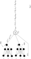
- Such an embodiment is schematically illustrated in Fig. 2 .
- the method may comprise training the first neural network NN1 using the measured temperature data T true ( x , t) to thereby obtain the temperature model, wherein the temperature model is thereafter used for training the neural network system.
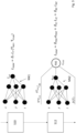
- the first neural network NN1 may be trained in a first step S10 and the result from the first step S10 is thereafter used for training the neural network system, see step S12 in Fig. 3 .
- the step S10 of obtaining the temperature model comprises establishing a set of temperature entities ⁇ T associated with a probability distribution on the solution to the temperature model.
- the temperature entities comprise, alternatively are constituted by, temperature hyperparameters, wherein training the first neural network NN1 comprises generating a temperature cost function L Total that includes the set of temperature entities ⁇ T , the estimated temperature data T est ( x , t) and the measured temperature data T true ( x , t) and
- the temperature entities ⁇ T such as the temperature hyperparameters ⁇ T , may for instance be determined using an iterative procedure that carries out a number of iterations.
- the temperature entities ⁇ T may thereafter be used in order to determine the estimated temperature data T est ( x , t).
- the procedure of training the first neural network NN1 may be performed in a manner presented in US 10,963,540 B2 . It should be noted that any one of the training procedures presented in US 10,963,540 B2 may be applied to each one of the embodiments presented hereinabove with reference to Fig. 2 and Fig. 3 , respectively.
- the neural network system further uses the following: a temperature dependent material property D(T), such as heat conductivity, of at least a portion of the enclosure 14.
- D(T) a temperature dependent material property
- Fig. 2 trains the first neural network NN1 and the neural network system simultaneously and the Fig. 3 embodiment trains the first neural network NN1 before the neural network system simultaneously, other embodiments of the method of the present inventions are also contemplated.
- embodiments of the method of the invention may employ an iterative procedure in which the first neural network NN1 is only partly trained and that the temperature model obtained from such a partial training is thereafter used for training the neural network system. Thereafter, the first neural network NN1 may be trained further and the thus resulting temperature model may be used for further training the neural network system.
- the first neural network NN1 may be trained only partly by choosing a first predetermined temperature range and determine e.g. temperature entities ⁇ T such that a corresponding value of the temperature cost function L Total is within the first predetermined temperature range. Thereafter, in the further training of the first neural network NN1, a second predetermined temperature range that is narrower than the first predetermined temperature range, may be used that the temperature entities ⁇ T may be determined such that a corresponding value of the temperature cost function L Total is within the second predetermined temperature range.
- a second aspect of the present invention relates to a method for evaluating a static electric induction device assembly 10.
- the static electric induction device assembly 10 comprises a static electric induction device 12 located in the interior of an enclosure 14.
- the assembly 10 further comprises a liquid 18 located in the interior of the enclosure 14, which liquid 18 at least partly surrounds the static electric induction device 12.
- the method comprises:
- the enclosure 14 may have an exterior surface 22 facing away from the in the interior of the enclosure 14, wherein the measurement assembly comprises one or more sensing devices adapted to sense the temperature on a plurality of different locations on the exterior surface 22 of the enclosure 14.
- the step of determining the measured temperature data may comprises transforming images captured by the one or more thermal cameras 24 onto the exterior surface.
- the method of the present invention comprises generating a temperature model for estimated temperature data.
- the estimated temperature data corresponds to an estimated temperature T est ( x , t) in each one of the plurality of different locations x of the static electric induction device assembly 10 as a function of time t.
- the temperature model comprises a first neural network NN1 (see each one of Fig. 2 and Fig. 3 ) representing the estimated temperature data T est ( x , t) as well as the measured temperature data T true ( x , t).
- the estimated temperature data T est ( x , t) may be determined in a separate step S10 by training a first neural network NN1 using the measured temperature data T true ( x , t).
- the result of the step S10 in Fig. 3 may be the estimated temperature data T est ( x , t).
- the step of obtaining the temperature model comprises establishing a set of temperature entities ⁇ T associated with a probability distribution on the solution to the temperature model.
- the temperature entities ⁇ T comprise, alternatively are constituted by, temperature hyperparameters, and training the first neural network NN1 comprises generating a temperature cost function L Total that includes set of temperature entities ⁇ T , the estimated temperature data T est ( x , t) and the measured temperature data T true ( x , t).
- the procedure of obtaining the temperature model may comprise
- the unknown entity in Eq. 2 above relates to the enclosure wall heat losses q wall (I(t),T).
- the enclosure wall heat losses q wall (I(t),T) may be estimated by training a neural network system that uses at least the following entities: the time dependent partial differential equation (see e.g. Eq. 2), information from the temperature model (see e.g. Eq. 2) and a second neural network NN2 for the physical quantity.
- the above-mentioned training may be performed in a separate step S12 as indicated in Fig. 3 .
- an estimate q est (I(t),T) of the enclosure wall heat losses may be determined by establishing a set of partial differential equation entities ⁇ PDE , ⁇ IC, ⁇ BC associated with a probability distribution on the solution to the time dependent partial differential equation.
- the partial differential equation cost function L total may comprise at least one of the following:
- the partial differential equation cost function L total includes each one of the entities listed in the above three items but it is also envisaged that other implementations of the partial differential equation cost function L total may include only one or two of the entities listed in the above three items.
- the residual e PDE associated with the time dependent partial differential equation may be determined using at least information from the temperature model.
- the method of the invention may also be used for other examples of the physical quantity.
- the physical entity may relate to stray losses in metallic parts of the static electric induction device 12 and/or hotspot temperatures associated with the static electric induction device 12.
Landscapes
- Engineering & Computer Science (AREA)
- Physics & Mathematics (AREA)
- Evolutionary Computation (AREA)
- Artificial Intelligence (AREA)
- General Physics & Mathematics (AREA)
- Theoretical Computer Science (AREA)
- Medical Informatics (AREA)
- Computer Vision & Pattern Recognition (AREA)
- Software Systems (AREA)
- Computer Hardware Design (AREA)
- General Engineering & Computer Science (AREA)
- Geometry (AREA)
- Chemical & Material Sciences (AREA)
- Combustion & Propulsion (AREA)
- Automation & Control Theory (AREA)
- Health & Medical Sciences (AREA)
- Testing Or Calibration Of Command Recording Devices (AREA)
- Monitoring And Testing Of Nuclear Reactors (AREA)
- General Induction Heating (AREA)
- Measuring Temperature Or Quantity Of Heat (AREA)
Abstract
- using a time dependent partial differential equation representing a physical condition of the static electric induction device assembly (10) during the reference time range (ΔTref), wherein the physical quantity forms a source term of the partial differential equation;
- generating a temperature model for estimated temperature data, the estimated temperature data corresponding to an estimated temperature (Test(x, t)) in each one of the plurality of different locations (x) of the static electric induction device assembly (10) as a function of time (t), the temperature model comprising a first neural network (NN1) representing the estimated temperature data (Test(x, t)) as well as the measured temperature data (Ttrue(x, t)), and
- estimating the physical quantity by training a neural network system that uses at least the following entities: the time dependent partial differential equation, information from the temperature model and a second neural network (NN2) for the physical quantity.
Description
- The present invention relates to a method for estimating a physical quantity of a static electric induction device assembly. Moreover, the present invention relates to each one of a computer program product, a non-transitory computer-readable storage medium and a control unit.
- In a static electric induction device assembly, such as for example an assembly comprising a transformer or a shunt reactor, it may be desired to obtain information indicative of a physical quantity thereof. Purely by way of example, it may be desired to determine information relating to heat losses associated with at least a portion of the static electric induction device assembly.
- However, it may be a challenging task to obtain such information from e.g. a numerical model of the static electric induction device assembly. Moreover, since a static electric induction device may comprise a static electric induction device surrounded by liquid in an enclosure, such as a tank, it may also be a challenging task to determine the above information by means of experiments.
- In view of the above, an object of the present invention is to provide a method for estimating a physical quantity of a static electric induction device assembly, which method provides appropriately reliable results.
- The above object is achieved by a method according to claim 1.
- As such, the present invention relates to a method for estimating a physical quantity of a static electric induction device assembly. The static electric induction device assembly comprises an enclosure, a static electric induction device and a liquid whereby the enclosure accommodates the static electric induction device and the liquid such that the static electric induction device is at least partially, preferably fully, submerged into the liquid. The method comprises using measured temperature data obtained from a measurement assembly. The measured temperature data comprises a temperature in each one of a plurality of different locations of the static electric induction device assembly as a function of time for a reference time range when the static electric induction device assembly is in a condition in which at least a portion of the static electric induction device generates heat during at least a portion of the reference time range.
- The method further comprises:
- using a time dependent partial differential equation representing a physical condition of the static electric induction device assembly during the reference time range, wherein the physical quantity forms a source term of the partial differential equation;
- generating a temperature model for estimated temperature data, the estimated temperature data corresponding to an estimated temperature in each one of the plurality of different locations of the static electric induction device assembly as a function of time, the temperature model comprising a first neural network representing the estimated temperature data as well as the measured temperature data, and
- estimating the physical quantity by training a neural network system that uses at least the following entities: the time dependent partial differential equation, information from the temperature model and a second neural network for the physical quantity.
- The method according to the above implies an appropriate accuracy in the estimation of the physical quantity since the method uses information from the temperature model for estimating the physical quantity of interest.
- As used herein, the term expression "source term" of the partial differential equation is intended to encompass a term relating to a net inflow or a net outflow of a physical entity in a portion of the static electric induction device assembly.
- As an example, a steady state temperature distribution of a body may generally be established by solving the Laplace equation ΔT = 0 with appropriate boundary conditions. However, if there is a net inflow or a net outflow of a physical entity in a portion of the body which can be represented by a function J, the Laplace equation may be reformulated in accordance with the following: ΔT = J. As such, the function J is a source term in the thus reformulated Laplace equation.
- It should be noted that the function J, depending on the partial differential equation and the characteristics of the net inflow or net outflow, may be dependent on one more of a plurality of parameters, such as at least one of the following parameters: time t, location x and temperature T. Thus, the source term may for example be formulated in accordance with the following: J = J(t, x , T).
- Purely by way of example, the time dependent partial differential equation may be a heat equation that has a temperature T as an unknown variable. This example can apply to every embodiment of the present invention.
- Optionally, the method further comprises establishing a set of partial differential equation entities associated with a probability distribution on the solution to the time dependent partial differential equation. The method further comprising generating a partial differential equation cost function that includes the partial differential equation entities, wherein training the neural network system comprises:
- determining the set of partial differential equation entities such that a corresponding value of the partial differential equation cost function is within a predetermined range and/or
- varying the set of partial differential equation entities until a predetermined stop condition has been obtained.
- The above features imply that training the neural network system may comprise an iterative procedure that carries out a number of iterations. This in turn implies an appropriately large possibility to obtain reasonably accurate results.
- Optionally, the partial differential equation cost function comprises at least one of the following:
- a set of residual entities and a residual associated with the time dependent partial differential equation, preferably the residual entities comprising, alternatively being constituted by, residual functionals;
- a set of boundary condition entities and at least one boundary condition associated with the time dependent partial differential equation, preferably the boundary condition entities comprising, alternatively being constituted by, boundary condition functionals, and
- a set of initial condition entities and at least one initial condition associated with the time dependent partial differential equation, preferably the initial condition entities comprising, alternatively being constituted by, initial condition functionals.
- As used herein, the term "functional" is intended to encompass a mapping from a space into a field of real or complex numbers. The space may comprise functions whereby a functional may be referred to as a function that uses another function as input. As a non-limiting example, an integral may be an example of a functional since the integral uses a function as an input and the result from the integral may be a real or complex number, depending e.g. on the characteristic of the function input into the integral.
- Optionally, the residual associated with the time dependent partial differential equation is determined using at least information from the temperature model, preferably using the estimated temperature in each one of the plurality of different locations of the static electric induction device assembly as a function of time. As such, information from the temperature model, for instance the estimated temperature, may be used for determining the above-mentioned set of residual entities. This in turn implies that the measured temperature data, being represented by the temperature model, may be used when determining the above-mentioned residual. However, the measured temperature data per se need to be used for determining the residual. Instead, the measured temperature data may be represented by the first neural network which in turn forms part of the temperature model. This implies an appropriately high level of accuracy for the residual, since the temperature model may be associated with a level of accuracy exceeding the accuracy of the measured temperature data as such. For instance, the temperature model may provide temperature information in locations and/or instances in which the temperature is not measured.
- Optionally, the set of partial differential equation entities comprises a set of temperature entities associated with a probability distribution on the solution to the temperature model, wherein the partial differential equation cost function comprises an addend including the temperature entities and a temperature cost function including the estimated temperature data and the measured temperature data. Preferably, the temperature entities comprise, alternatively are constituted by, temperature hyperparameters.
- Optionally, the method comprises training the first neural network using the measured temperature data to thereby obtain the temperature model, wherein the temperature model is thereafter used for training the neural network system.
- As have been intimated above, training the neural network system using the temperature model rather than the measured temperature data only implies an appropriately high accuracy of the method.
- Optionally, the step of obtaining the temperature model comprises establishing a set of temperature entities associated with a probability distribution on the solution to the temperature model. Preferably the temperature entities comprise, alternatively are constituted by, temperature hyperparameters, wherein training the first neural network comprises generating a temperature cost function that includes a set of temperature entities, the estimated temperature data and the measured temperature data and
- determining the set of temperature entities such that a corresponding value of the temperature cost function is within a predetermined temperature range and/or
- varying the set of temperature entities until a predetermined stop condition has been obtained.
- As such, the temperature entities, such as the temperature hyperparameters, may for instance be determined using an iterative procedure that carries out a number of iterations. This in turn implies an appropriately large possibility to obtain reasonably accurate results.
- Optionally, the physical quantity represents at least one of the following of the static electric induction device assembly: heat losses through the enclosure, stray losses in metallic parts of the static electric induction device and hotspot temperatures associated with the static electric induction device.
- Optionally, the static electric induction device comprises a transformer and/or a shunt reactor.
- Optionally, the neural network system further uses a temperature dependent material property, such as heat conductivity, of at least a portion of the enclosure.
- A second aspect of the present invention relates to a method for evaluating a static electric induction device assembly. The static electric induction device assembly comprises a static electric induction device located in the interior of an enclosure. The assembly further comprising a liquid located in the interior of an enclosure, which liquid surrounds the static electric induction device. The method comprises:
- arranging the static electric induction device assembly in a condition in which at least a portion of the static electric induction device generates heat;
- determining measured temperature data using a measurement assembly, the measured temperature data comprising a temperature in each one of a plurality of different locations of the static electric induction device assembly as a function of time for a reference time range when the static electric induction device assembly is the condition in which at least a portion of the static electric induction device generates heat during at least a portion of the reference time range, and
- estimating a physical quantity of a static electric induction device assembly using a method according the first aspect of the present invention.
- Optionally, the enclosure has an exterior surface facing away from interior of the enclosure, wherein the measurement assembly comprises one or more sensing devices adapted to sense the temperature on a plurality of different locations on the exterior surface of the enclosure.
- Optionally, the measurement assembly comprises one or more thermal cameras and wherein the step of determining measured temperature data comprises capturing images of the exterior surface using the one or more thermal cameras.
- Optionally, the step of determining the measured temperature data comprises transforming images captured by the one or more thermal cameras onto the exterior surface.
- A third aspect of the present invention relates to a computer program product comprising program code for performing, when executed by a processor device, the method of the first aspect of the present invention.
- A fourth aspect of the present invention relates to a non-transitory computer-readable storage medium comprising instructions, which when executed by a processor device, cause the processor device to perform the method of the first aspect of the present invention.
- A fifth aspect of the present invention relates to a control unit arranged to perform the method of the first aspect of the present invention.
- With reference to the appended drawings, below follows a more detailed description of embodiments of the disclosure cited as examples.
- In the drawings:
- Fig. 1
- is a schematic illustration of a static electric induction device assembly;
- Fig. 2
- is a schematic illustration of a method embodiment of the present invention, and
- Fig. 3
- is a schematic illustration of another method embodiment of the present invention.
- Preferred embodiments of the present disclosure will be discussed hereinbelow with reference to the appended drawings.
-
Figs. 1 schematically illustrates an embodiment of a static electricinduction device assembly 10. The static electric induction device assembly comprises anenclosure 14, a staticelectric induction device 12 and a liquid 18 whereby theenclosure 14 accommodates the staticelectric induction device 12 and the liquid 18 such that the staticelectric induction device 12 is at least partially, preferably fully, submerged into the liquid 18. In theFig. 1 embodiment, the staticelectric induction device 12 is fully submerged into the liquid 18. As a non-limiting example, the staticelectric induction device 12 may comprise, or even be constituted by, a transformer and/or a shunt reactor. Moreover, as indicated inFig. 1 , theenclosure 14 may be delimited by anenclosure wall 16. - Purely by way of example, the
enclosure wall 16 may comprise, or even be constituted by, a metallic material such as steel. - Moreover, as a non-limiting example, the
enclosure 14 may be referred to as a tank. - Further, purely by way of example, the liquid 18 may comprise or even be constituted by a dielectric liquid, such as a mineral oil.
- The static electric
induction device assembly 10 may be adapted to assume a condition in which at least a portion of the staticelectric induction device 12 generates heat. Purely by way of example, and as indicated inFig. 1 , when the staticelectric induction device 12 is operated, it may generate interior heat losses qint. As non-limiting examples, if the staticelectric induction device 12 comprises, or even is constituted by, a transformer and/or a shunt reactor, the interior heat losses qint may be caused by a core (not shown) and windings (not shown) of the staticelectric induction device 12. Such interior heat losses qint may propagate via the liquid 18 towards theenclosure wall 16. - Moreover, heat may propagate through the
enclosure wall 16 resulting in enclosure wall heat losses qwall. Purely by way of example, the magnitude of the enclosure wall heat losses qwall may be dependent on the temperature difference over theenclosure wall 16, viz the difference between the temperature of the liquid 18 on the inside of the enclosure wall and the temperature of the fluid, such as air, ambient of theenclosure wall 16, as well as an enclosure heat transfer parameter, such as a wall diffusion coefficient kwall indicative of a diffusion over theenclosure wall 16. - The method of the present invention comprises using measured temperature data obtained from a
measurement assembly 20. The measured temperature data comprises a temperature Ttrue(x, t) in each one of a plurality of different locations of the static electricinduction device assembly 10 as a function of time t for a reference time range ΔTref when the static electricinduction device assembly 10 is in a condition in which at least a portion of the staticelectric induction device 12 generates heat during at least a portion of the reference time range ΔTref. For the sake of completeness, it should be noted that a location is herein generally denoted by an x in order to elucidate that the location may be expressed in terms of one, two or three dimensions, for instance depending on the characteristics of the measured temperature data. - As indicated in
Fig. 1 , themeasurement assembly 20 may comprise one or more measurement entities. - In the
Fig. 1 embodiment, theenclosure 14 has anexterior surface 22 facing away from the interior of theenclosure 14. Purely by way of example, and as indicated inFig. 1 , theexterior surface 22 may be the outer surface of theenclosure wall 16. Moreover, themeasurement assembly 20 may comprise one or more sensing devices adapted to sense the temperature on a plurality of different locations on theexterior surface 22 of theenclosure 14. - Purely by way of example, the
measurement assembly 20 may comprise one or more thermal cameras 24 (only one camera is indicated inFig. 1 ) and the step of determining measured temperature data may comprise capturing images of the exterior surface using the one or more thermal cameras. - However, implementations of the
measurement assembly 20 may comprise other types of sensors. To this end, reference is again made toFig. 1 in which anarray 26 of temperature sensors is located within the interior of theenclosure 14 wherein each temperature sensor in thearray 26 for instance may measure a temperature of the liquid 18 located in the interior of theenclosure 14. - For the sake of completeness, it should be noted that implementations of the
measurement assembly 20 may comprise a plurality of different sensors of different types. - Irrespectively of how the temperature Ttrue(x, t) in each one of the plurality of different locations of the static electric
induction device assembly 10 as a function of time t for the reference time range ΔTref has been determined, the method of the present invention comprises: - using a time dependent partial differential equation representing a physical condition of the static electric induction device assembly during the reference time range ΔTref, wherein the physical quantity forms a source term of the partial differential equation;
- generating a temperature model for estimated temperature data Test(x, t), the estimated temperature data Test(x, t) corresponds to an estimated temperature in each one of the plurality of different locations of the static electric
induction device assembly 10 as a function of time t, the temperature model comprising a first neural network NN1 representing the estimated temperature data Test(x, t) as well as the measured temperature data Ttrue(x, t), and - estimating the physical quantity by training a neural network system that uses at least the following entities: the time dependent partial differential equation, information from the temperature model and a second neural network NN2 for the physical quantity.
- As non-limiting examples, the physical quantity may represent at least one of the following of the static electric induction device assembly 10: heat losses through the
enclosure 14, stray losses in metallic parts of the staticelectric induction device 12 and hotspot temperatures associated with the staticelectric induction device 12. - By way of example only, the neural network system may be referred to as a physics-informed neural network.
- Moreover,
Fig. 1 indicates acontrol unit 28. Purely by way of example, thecontrol unit 28 may be arranged to perform the method of the first aspect of the present invention. To this end, though purely by way of example, thecontrol unit 28 may be adapted to receive information from relevant entities, such as themeasurement assembly 20 and the staticelectric induction device 12. - Purely by way of example, the method further comprises establishing a set of partial differential equation entities βPDE, βIC, βBC associated with a probability distribution on the solution to the time dependent partial differential equation. The method further comprises generating a partial differential equation cost function Ltotal that includes the partial differential equation entities βPDE, βIC, βBC, wherein training the neural network system comprises:
- determining the set of partial differential equation entities βPDE, βIC, βBC such that a corresponding value of the partial differential equation cost function Ltotal is within a predetermined range and/or
- varying the set of partial differential equation entities until a predetermined stop condition has been obtained.
- As a non-limiting example, the partial differential equation cost function may comprise at least one of the following:
- a set of residual entities βPDE and a residual ePDE associated with the time dependent partial differential equation, preferably the residual entities comprising βPDE , alternatively being constituted by, residual functionals;
- a set of boundary condition entities βBC and at least one boundary condition LBC associated with the time dependent partial differential equation, preferably the boundary condition entities comprising, alternatively being constituted by, boundary condition functionals, and
- a set of initial condition entities βIC and at least one initial condition LIC associated with the time dependent partial differential equation, preferably the initial condition entities comprising, alternatively being constituted by, initial condition functionals.
- As a non-limiting example, the residual ePDE associated with the time dependent partial differential equation may be determined using at least information from the temperature model, preferably using the estimated temperature Test(x, t) in each one of the plurality of different locations x of the static electric
induction device assembly 10 as a function of time t. As such, though by way of example only, the residual ePDE may be determined using at least portions of the estimated temperature data Test(x, t). - Purely by way of example, the set of partial differential equation entities comprises a set of temperature entities βT associated with a probability distribution on the solution to the temperature model, wherein the partial differential equation cost function comprises an addend βTLT including the temperature entities βT and a temperature cost function LT including the estimated temperature data Test(x, t) and the measured temperature data Ttrue(x, t). Preferably, the temperature entities βT comprise, alternatively are constituted by, temperature hyperparameters.
- As such, in embodiments of the invention, the first neural network NN1 and the neural network system may be trained simultaneously. Such an embodiment is schematically illustrated in
Fig. 2 . - Optionally, the method may comprise training the first neural network NN1 using the measured temperature data Ttrue(x, t) to thereby obtain the temperature model, wherein the temperature model is thereafter used for training the neural network system.
- As such, as exemplified in
Fig. 3 , in embodiments of the invention, the first neural network NN1 may be trained in a first step S10 and the result from the first step S10 is thereafter used for training the neural network system, see step S12 inFig. 3 . - Moreover, as indicated in
Fig. 3 , the step S10 of obtaining the temperature model comprises establishing a set of temperature entities βT associated with a probability distribution on the solution to the temperature model. Preferably, the temperature entities comprise, alternatively are constituted by, temperature hyperparameters, wherein training the first neural network NN1 comprises generating a temperature cost function LTotal that includes the set of temperature entities βT , the estimated temperature data Test(x, t) and the measured temperature data Ttrue(x, t) and - determining the set of temperature entities βT such that a corresponding value of the temperature cost function LTotal is within a predetermined temperature range and/or
- varying the set of temperature entities βT until a predetermined stop condition has been obtained.
- As such, the temperature entities βT , such as the temperature hyperparameters βT , may for instance be determined using an iterative procedure that carries out a number of iterations. The temperature entities βT may thereafter be used in order to determine the estimated temperature data Test(x, t).
- It should be noted that the procedure of training the first neural network NN1 may be performed in a manner presented in
US 10,963,540 B2 US 10,963,540 B2 Fig. 2 andFig. 3 , respectively. - Optionally, the neural network system further uses the following: a temperature dependent material property D(T), such as heat conductivity, of at least a portion of the
enclosure 14. Such a possibility is indicated in each one ofFig. 2 andFig. 3 . - It should be noted that although the
Fig. 2 embodiment trains the first neural network NN1 and the neural network system simultaneously and theFig. 3 embodiment trains the first neural network NN1 before the neural network system simultaneously, other embodiments of the method of the present inventions are also contemplated. - Purely by way of example, it is contemplated that embodiments of the method of the invention may employ an iterative procedure in which the first neural network NN1 is only partly trained and that the temperature model obtained from such a partial training is thereafter used for training the neural network system. Thereafter, the first neural network NN1 may be trained further and the thus resulting temperature model may be used for further training the neural network system.
- Purely by way of example, the first neural network NN1 may be trained only partly by choosing a first predetermined temperature range and determine e.g. temperature entities βT such that a corresponding value of the temperature cost function LTotal is within the first predetermined temperature range. Thereafter, in the further training of the first neural network NN1, a second predetermined temperature range that is narrower than the first predetermined temperature range, may be used that the temperature entities βT may be determined such that a corresponding value of the temperature cost function LTotal is within the second predetermined temperature range.
- A second aspect of the present invention relates to a method for evaluating a static electric
induction device assembly 10. The static electricinduction device assembly 10 comprises a staticelectric induction device 12 located in the interior of anenclosure 14. Theassembly 10 further comprises a liquid 18 located in the interior of theenclosure 14, which liquid 18 at least partly surrounds the staticelectric induction device 12. The method comprises: - arranging the static electric
induction device assembly 10 in a condition in which at least a portion of the staticelectric induction device 12 generates heat; - determining measured temperature data Ttrue(x, t) using a
measurement assembly 20, the measured temperature data Ttrue(x, t) comprising a temperature in each one of a plurality of different locations of the static electric induction device assembly as a function of time for a reference time range ΔTref when the static electricinduction device assembly 10 is the condition in which at least a portion of the staticelectric induction device 12 generates heat during at least a portion of the reference time range ΔTref, and - estimating a physical quantity of a static electric induction device assembly using a method according the first aspect of the present invention.
- Again with reference to
Fig. 1 , theenclosure 14 may have anexterior surface 22 facing away from the in the interior of theenclosure 14, wherein the measurement assembly comprises one or more sensing devices adapted to sense the temperature on a plurality of different locations on theexterior surface 22 of theenclosure 14. - As a non-limiting example, the step of determining the measured temperature data may comprises transforming images captured by the one or more
thermal cameras 24 onto the exterior surface. - The method in accordance with the present invention will now be exemplified by the following time dependent partial differential equation:

- T= T(x, t) represents a temperature in each one of a plurality of different locations (x) as function of time (t);
- D(T) represents a temperature dependent material property, such as heat conductivity, of at least a portion of the
enclosure 14, and - qwall(I(t),T) represents enclosure wall heat losses, wherein such heat losses may be dependent on each one of the current I(t) fed to the static
electric induction device 12 and the temperature T, such as the temperature of an inner side of theenclosure wall 16. - As may be realised from the above, the physical quantity forming a source term of the partial differential equation as presented in Eq. 1 above is exemplified above by the enclosure wall heat losses qwall(I(t),T).
- Moreover, as has been indicated in the above description, the method of the present invention comprises generating a temperature model for estimated temperature data. The estimated temperature data corresponds to an estimated temperature Test(x, t) in each one of the plurality of different locations x of the static electric
induction device assembly 10 as a function of time t. The temperature model comprises a first neural network NN1 (see each one ofFig. 2 andFig. 3 ) representing the estimated temperature data Test(x, t) as well as the measured temperature data Ttrue(x, t). - With reference to
Fig. 3 , the estimated temperature data Test(x, t) may be determined in a separate step S10 by training a first neural network NN1 using the measured temperature data Ttrue(x, t). As such, the result of the step S10 inFig. 3 may be the estimated temperature data Test(x, t). - To this end, and as indicated in
Fig. 3 , the step of obtaining the temperature model comprises establishing a set of temperature entities βT associated with a probability distribution on the solution to the temperature model. - Preferably, although not necessarily, the temperature entities βT comprise, alternatively are constituted by, temperature hyperparameters, and training the first neural network NN1 comprises generating a temperature cost function LTotal that includes set of temperature entities βT , the estimated temperature data Test(x, t) and the measured temperature data Ttrue(x, t). As a non-limiting example, the estimated temperature data Test(x, t) and the measured temperature data Ttrue(x, t) may be included in an cost function LT (Test(x, t), Ttrue(x, t)) and the total cost function may be defined in accordance with the following: L Total= βT LT (Test(x, t), Ttrue(x, t)).
- Moreover, though purely by way of example, the procedure of obtaining the temperature model may comprise
- determining the set of temperature entities βT such that a corresponding value of the temperature cost function LTotal is within a predetermined temperature range and/or
- varying the set of temperature entities βT until a predetermined stop condition has been obtained.
- Irrespectively of how the temperature model is determined from which the estimated temperature data Test(x, t) is determined, the thus obtained estimated temperature data Test(x, t) may thereafter be input in Eq. 1 above in accordance with the following:

- As may be realized from the above, using the estimated temperature data Test(x, t) in Eq. 2 above and for instance assuming that the current I(t) is known, the unknown entity in Eq. 2 above relates to the enclosure wall heat losses qwall(I(t),T).
- The enclosure wall heat losses qwall(I(t),T) may be estimated by training a neural network system that uses at least the following entities: the time dependent partial differential equation (see e.g. Eq. 2), information from the temperature model (see e.g. Eq. 2) and a second neural network NN2 for the physical quantity. Purely by way of example, the above-mentioned training may be performed in a separate step S12 as indicated in
Fig. 3 . - As such, an estimate qest(I(t),T) of the enclosure wall heat losses may be determined by establishing a set of partial differential equation entities βPDE, βIC, βBC associated with a probability distribution on the solution to the time dependent partial differential equation.
- The method may further comprise generating a partial differential equation cost function Ltotal that includes the partial differential equation entities βPDE, βIC, βBC and training the neural network system may comprise:
- determining the set of partial differential equation entities βPDE, βIC, βBC such that a corresponding value of the partial differential equation cost function Ltotal is within a predetermined range and/or
- varying the set of partial differential equation entities βPDE, βIC, βBC until a predetermined stop condition has been obtained.
- Moreover, as indicated in
Fig. 3 for example, the partial differential equation cost function Ltotal may comprise at least one of the following: - a set of residual entities βPDE and a residual ePDE associated with the time dependent partial differential equation, preferably the residual entities ePDE comprising, alternatively being constituted by, residual functionals;
- a set of boundary condition entities βBC and at least one boundary condition LBC associated with the time dependent partial differential equation, preferably the boundary condition entities βBC comprising, alternatively being constituted by, boundary condition functionals, and
- a set of initial condition entities βIC and at least one initial condition LIC associated with the time dependent partial differential equation, preferably the initial condition entities βIC comprising, alternatively being constituted by, initial condition functionals.
- In the
Fig. 3 example, the partial differential equation cost function Ltotal includes each one of the entities listed in the above three items but it is also envisaged that other implementations of the partial differential equation cost function Ltotal may include only one or two of the entities listed in the above three items. - Furthermore, in implementations of the method of the invention in which the partial differential equation cost function Ltotal comprises the set of residual entities βPDE , the residual ePDE associated with the time dependent partial differential equation may be determined using at least information from the temperature model.
- To this end, although purely by way of example, the method may comprise that the neural network system tests various residual entities βPDE , for instance various residual functionals. For each residual entity βPDE assessed, the residual ePDE may be determined using the thus assessed residual entity βPDE and the estimated temperature data Test(x, t). Purely by way of example, the residual ePDE may be determined in accordance with the following:


- By determining appropriate entities, such as appropriate residual entities βPDE , it is possible to determine an estimate qest(I(t),T) of the enclosure wall heat losses being the physical quantity of interest in the above example.
- It should be noted that although the above example uses the enclosure wall heat losses as an example, the method of the invention may also be used for other examples of the physical quantity. As non-limiting examples, the physical entity may relate to stray losses in metallic parts of the static
electric induction device 12 and/or hotspot temperatures associated with the staticelectric induction device 12. - In such examples, the procedure presented above starting with Eq. 1 may be employed but the source term of said partial differential equation in Eq. 1 may be updated, for instance by replacing the enclosure wall heat losses qwall(I(t),T) source term by another source term or by adding another source term to the source term formed by the enclosure wall heat losses qwall(I(t),T).
- Moreover, although the example presented above starting with Eq. 1 has included two separate steps S10 and S12, it is also possible that other examples of the method of the present invention may be performed in a single step.
- Finally, it is to be understood that the described properties of the method for estimating a physical quantity of a static electric induction device assembly are applicable to all embodiments of such a method which fall within the ambit of the appended claims.
Claims (15)
- A method for estimating a physical quantity of a static electric induction device assembly (10), said static electric induction device assembly (10) comprising an enclosure (14), a static electric induction device (12) and a liquid (18) whereby said enclosure (14) accommodates said static electric induction device (12) and said liquid (18) such that said static electric induction device (12) is at least partially, preferably fully, submerged into said liquid (18), said method comprising using measured temperature data obtained from a measurement assembly (20), said measured temperature data comprising a temperature (Ttrue(x, t)) in each one of a plurality of different locations (x) of said static electric induction device assembly (10) as a function of time (t) for a reference time range (ΔTref) when the static electric induction device assembly (10) is in a condition in which at least a portion of said static electric induction device (12) generates heat during at least a portion of said reference time range (ΔTref),
said method further comprising:- using a time dependent partial differential equation representing a physical condition of said static electric induction device assembly (10) during said reference time range (ΔTref), wherein said physical quantity forms a source term of said partial differential equation;- generating a temperature model for estimated temperature data, said estimated temperature data corresponding to an estimated temperature (Test(x, t)) in each one of said plurality of different locations (x) of said static electric induction device assembly (10) as a function of time (t), said temperature model comprising a first neural network (NN1) representing said estimated temperature data (Test(x, t)) as well as said measured temperature data (Ttrue(x, t)), and- estimating said physical quantity by training a neural network system that uses at least the following entities: said time dependent partial differential equation, information from said temperature model and a second neural network (NN2) for said physical quantity. - The method according to claim 1, wherein said method further comprises establishing a set of partial differential equation entities (βPDE, βIC, βBC) associated with a probability distribution on the solution to said time dependent partial differential equation, said method further comprising generating a partial differential equation cost function (Ltotal ) that includes said partial differential equation entities, wherein training said neural network system comprises:- determining said set of partial differential equation entities (βPDE, βIC, βBC) such that a corresponding value of said partial differential equation cost function (Ltotal ) is within a predetermined range and/or- varying said set of partial differential equation entities (βPDE, βIC, βBC) until a predetermined stop condition has been obtained.
- The method according to claim 2, wherein said partial differential equation cost function (Ltotal ) comprises at least one of the following:- a set of residual entities (βPDE ) and a residual (ePDE ) associated with said time dependent partial differential equation, preferably said residual entities (ePDE ) comprising, alternatively being constituted by, residual functionals;- a set of boundary condition entities (βBC ) and at least one boundary condition (LBC ) associated with said time dependent partial differential equation, preferably said boundary condition entities (βBC ) comprising, alternatively being constituted by, boundary condition functionals, and- a set of initial condition entities (βIC ) and at least one initial condition (LIC ) associated with said time dependent partial differential equation, preferably said initial condition entities (βIC ) comprising, alternatively being constituted by, initial condition functionals.
- The method according to claim 3, wherein said residual (ePDE ) associated with said time dependent partial differential equation is determined using at least information from said temperature model, preferably using said estimated temperature (Test(x, t)) in each one of said plurality of different locations (x) of said static electric induction device assembly (10) as a function of time (t).
- The method according to any one of claims 2 to 4, wherein said set of partial differential equation entities comprises a set of temperature entities (βT ) associated with a probability distribution on the solution to said temperature model, wherein said partial differential equation cost function comprises an addend (βTLT ) including said temperature entities (βT ) and a temperature cost function (LT ) including said estimated temperature data Test(x, t) and said measured temperature data Ttrue(x, t), preferably said temperature entities (βT ) comprise, alternatively are constituted by, temperature hyperparameters.
- The method according to any one of claim 1 to claim 4, wherein said method comprises training said first neural network (NN1) using said measured temperature data (Ttrue(x, t)) to thereby obtain said temperature model, wherein said temperature model is thereafter used for training said neural network system.
- The method according to claim 6, wherein the step of obtaining said temperature model comprises establishing a set of temperature entities (βT ) associated with a probability distribution on the solution to said temperature model preferably said temperature entities comprise, alternatively are constituted by, temperature hyperparameters, wherein training said first neural network comprises generating a temperature cost function (LTotal ) that includes set of temperature entities (βT ), said estimated temperature data (Test(x, t)) and said measured temperature data (Ttrue(x, t)) and- determining said set of temperature entities (βT ) such that a corresponding value of said temperature cost function (LTotal ) is within a predetermined temperature range and/or- varying said set of temperature entities (βT ) until a predetermined stop condition has been obtained.
- The method according to any one of the preceding claims, wherein said physical quantity represents at least one of the following of the static electric induction device assembly (10): heat losses through said enclosure (14), stray losses in metallic parts of the static electric induction device (12) and hotspot temperatures associated with said static electric induction device (12).
- The method according to any one of the preceding claims, wherein said neural network system further uses a temperature dependent material property (D(T)), such as heat conductivity, of at least a portion of said enclosure (14).
- A method for evaluating a static electric induction device assembly (10), said static electric induction device assembly (10) comprising a static electric induction device (12) located in the interior of an enclosure (14), said assembly further comprising a liquid (18) located in the interior of the enclosure (14), which liquid (18) surrounds said static electric induction device (12), said method comprising:- arranging said static electric induction device assembly (10) in a condition in which at least a portion of said static electric induction device (12) generates heat;- determining measured temperature data (Ttrue(x, t)) using a measurement assembly (20), said measured temperature data (Ttrue(x, t)) comprising a temperature in each one of a plurality of different locations (x) of said static electric induction device assembly (10) as a function of time (t) for a reference time range (ΔTref) when said static electric induction device assembly (10) is said condition in which at least a portion of said static electric induction device (12) generates heat during at least a portion of said reference time range (ΔTref), and- estimating a physical quantity of a static electric induction device assembly (10) using a method according to any one of the preceding claims.
- The method according to claim 10, wherein said enclosure (14) has an exterior surface (22) facing away from the in the interior of the enclosure (14), wherein said measurement assembly (20) comprises one or more sensing devices adapted to sense the temperature on a plurality of different locations on the exterior surface (22) of said enclosure (14).
- The method according to claim 11, wherein said measurement assembly (20) comprises one or more thermal cameras (24) and wherein said step of determining measured temperature data comprises capturing images of said exterior surface (22) using said one or more thermal cameras (24), preferably said step of determining said measured temperature data comprises transforming images captured by said one or more thermal cameras onto said exterior surface (22).
- A computer program product comprising program code for performing, when executed by a processor device, the method of any one of claims 1 - 9.
- A non-transitory computer-readable storage medium comprising instructions, which when executed by a processor device, cause the processor device to perform the method of any one of claims 1 - 9.
- A control unit (28) arranged to perform the method of any one of claims 1 - 9.
Priority Applications (8)
| Application Number | Priority Date | Filing Date | Title |
|---|---|---|---|
| EP23162860.3A EP4435397B1 (en) | 2023-03-20 | 2023-03-20 | A method for estimating a physical quantity of a static electric induction device assembly |
| EP23765514.7A EP4670014A1 (en) | 2023-03-20 | 2023-09-06 | Monitoring of electrical devices using physically informed neural machine learning |
| US19/167,217 US20260119751A1 (en) | 2023-03-20 | 2023-09-06 | Monitoring of electrical devices with physical informed neural machine learning |
| PCT/EP2023/074494 WO2024193833A1 (en) | 2023-03-20 | 2023-09-06 | Monitoring of electrical devices with physical informed neural machine learning |
| CN202380096171.6A CN120917389A (en) | 2023-03-20 | 2023-09-06 | Monitoring of electrical devices using physical information neural machine learning |
| CN202480010477.XA CN120641727A (en) | 2023-03-20 | 2024-03-15 | Method for estimating physical quantities of components of an electrostatic induction device |
| PCT/EP2024/057008 WO2024194194A1 (en) | 2023-03-20 | 2024-03-15 | A method for estimating a physical quantity of a static electric induction device assembly |
| US18/981,936 US20250117624A1 (en) | 2023-03-20 | 2024-12-16 | Method for estimating a physical quantity of a static electric induction device assembly |
Applications Claiming Priority (1)
| Application Number | Priority Date | Filing Date | Title |
|---|---|---|---|
| EP23162860.3A EP4435397B1 (en) | 2023-03-20 | 2023-03-20 | A method for estimating a physical quantity of a static electric induction device assembly |
Publications (2)
| Publication Number | Publication Date |
|---|---|
| EP4435397A1 true EP4435397A1 (en) | 2024-09-25 |
| EP4435397B1 EP4435397B1 (en) | 2025-12-10 |
Family
ID=85705009
Family Applications (2)
| Application Number | Title | Priority Date | Filing Date |
|---|---|---|---|
| EP23162860.3A Active EP4435397B1 (en) | 2023-03-20 | 2023-03-20 | A method for estimating a physical quantity of a static electric induction device assembly |
| EP23765514.7A Pending EP4670014A1 (en) | 2023-03-20 | 2023-09-06 | Monitoring of electrical devices using physically informed neural machine learning |
Family Applications After (1)
| Application Number | Title | Priority Date | Filing Date |
|---|---|---|---|
| EP23765514.7A Pending EP4670014A1 (en) | 2023-03-20 | 2023-09-06 | Monitoring of electrical devices using physically informed neural machine learning |
Country Status (4)
| Country | Link |
|---|---|
| US (1) | US20260119751A1 (en) |
| EP (2) | EP4435397B1 (en) |
| CN (2) | CN120917389A (en) |
| WO (2) | WO2024193833A1 (en) |
Cited By (1)
| Publication number | Priority date | Publication date | Assignee | Title |
|---|---|---|---|---|
| WO2026057162A1 (en) * | 2024-09-12 | 2026-03-19 | Hitachi Energy Ltd | A method for estimating a physical quantity of a static electric induction device assembly |
Citations (4)
| Publication number | Priority date | Publication date | Assignee | Title |
|---|---|---|---|---|
| CN102427218A (en) * | 2011-10-28 | 2012-04-25 | 武汉供电公司变电检修中心 | Transformer short-term overload capacity evaluation system based on artificial intelligence technology |
| US20160005522A1 (en) * | 2012-11-19 | 2016-01-07 | Aldo Dagnino | Profiling transformer of power system |
| CN105550472A (en) * | 2016-01-20 | 2016-05-04 | 国网上海市电力公司 | Prediction method of transformer winding hot-spot temperature based on neural network |
| US10963540B2 (en) | 2016-06-02 | 2021-03-30 | Brown University | Physics informed learning machine |
Family Cites Families (12)
| Publication number | Priority date | Publication date | Assignee | Title |
|---|---|---|---|---|
| KR102636362B1 (en) * | 2016-11-22 | 2024-02-14 | 삼성전자주식회사 | Method and apparatus for estimating state of battery |
| CN110851966B (en) * | 2019-10-30 | 2021-07-20 | 同济大学 | A digital twin model correction method based on deep neural network |
| US11379629B2 (en) * | 2020-02-21 | 2022-07-05 | Raytheon Technologies Corporation | System and process for designing internal components for a gas turbine engine |
| US11995882B2 (en) * | 2020-03-25 | 2024-05-28 | Ansys, Inc. | Machine-learning based solver of coupled-partial differential equations |
| CN115809695B (en) * | 2021-09-13 | 2025-06-13 | 华为技术有限公司 | A model training method based on physical information neural network and related device |
| CN114282448A (en) * | 2021-11-16 | 2022-04-05 | 北京百度网讯科技有限公司 | Flow field information acquisition method, model training method and device and electronic equipment |
| CN114819054B (en) * | 2022-03-11 | 2024-02-27 | 西北工业大学 | A power electronic system status monitoring method based on physical information neural network |
| CN114896865B (en) * | 2022-04-20 | 2024-07-23 | 北京航空航天大学 | An online prediction method of health status based on adaptive evolutionary neural network for digital twins |
| CN114966451B (en) * | 2022-06-06 | 2024-04-26 | 北京航空航天大学 | Power supply product residual service life online prediction method based on physical information neural network |
| CN115221798B (en) * | 2022-09-19 | 2022-12-30 | 中南大学 | Battery thermal process space-time modeling prediction method, system, equipment and medium |
| CN115438588B (en) * | 2022-09-29 | 2023-05-09 | 中南大学 | A temperature prediction method, system, device and storage medium for a lithium battery |
| CN115758874A (en) * | 2022-11-11 | 2023-03-07 | 中国电力科学研究院有限公司 | Power equipment heat transfer modeling method and system based on physical constraint neural network |
-
2023
- 2023-03-20 EP EP23162860.3A patent/EP4435397B1/en active Active
- 2023-09-06 WO PCT/EP2023/074494 patent/WO2024193833A1/en not_active Ceased
- 2023-09-06 CN CN202380096171.6A patent/CN120917389A/en active Pending
- 2023-09-06 US US19/167,217 patent/US20260119751A1/en active Pending
- 2023-09-06 EP EP23765514.7A patent/EP4670014A1/en active Pending
-
2024
- 2024-03-15 WO PCT/EP2024/057008 patent/WO2024194194A1/en not_active Ceased
- 2024-03-15 CN CN202480010477.XA patent/CN120641727A/en active Pending
Patent Citations (4)
| Publication number | Priority date | Publication date | Assignee | Title |
|---|---|---|---|---|
| CN102427218A (en) * | 2011-10-28 | 2012-04-25 | 武汉供电公司变电检修中心 | Transformer short-term overload capacity evaluation system based on artificial intelligence technology |
| US20160005522A1 (en) * | 2012-11-19 | 2016-01-07 | Aldo Dagnino | Profiling transformer of power system |
| CN105550472A (en) * | 2016-01-20 | 2016-05-04 | 国网上海市电力公司 | Prediction method of transformer winding hot-spot temperature based on neural network |
| US10963540B2 (en) | 2016-06-02 | 2021-03-30 | Brown University | Physics informed learning machine |
Cited By (1)
| Publication number | Priority date | Publication date | Assignee | Title |
|---|---|---|---|---|
| WO2026057162A1 (en) * | 2024-09-12 | 2026-03-19 | Hitachi Energy Ltd | A method for estimating a physical quantity of a static electric induction device assembly |
Also Published As
| Publication number | Publication date |
|---|---|
| EP4435397B1 (en) | 2025-12-10 |
| US20260119751A1 (en) | 2026-04-30 |
| WO2024194194A1 (en) | 2024-09-26 |
| WO2024193833A1 (en) | 2024-09-26 |
| CN120917389A (en) | 2025-11-07 |
| EP4670014A1 (en) | 2025-12-31 |
| CN120641727A (en) | 2025-09-12 |
Similar Documents
| Publication | Publication Date | Title |
|---|---|---|
| CN110780164B (en) | Insulator infrared fault location and diagnosis method and device based on YOLO | |
| EP3229156B1 (en) | Predicting cracking in cooled metal or alloy components | |
| EP4435397B1 (en) | A method for estimating a physical quantity of a static electric induction device assembly | |
| EP2034282A1 (en) | Method and apparatus for measuring medium layers and interfaces between them using a multi-sensor probe | |
| EP3716205A1 (en) | An apparatus for hot spot sensing | |
| DE102021129342B3 (en) | Method and system for determining the temperature of a fluid flowing through a conduit body | |
| CN115752739B (en) | A temperature compensation method, device and electronic equipment | |
| KR20210110661A (en) | Analysis system and analysis method | |
| EP4163589B1 (en) | Estimation device, estimation method, and computer program product for estimating deposit thickness | |
| US12460927B2 (en) | Estimation device, estimation method, and non-transitory computer-readable recording medium for thickness of precipitate | |
| Diniz et al. | Methodology for estimating measurement uncertainty in the dynamic calibration of industrial temperature sensors | |
| Ho et al. | Accuracy enhancement of measurand estimate on the base of additive combined measurements | |
| US20250117624A1 (en) | Method for estimating a physical quantity of a static electric induction device assembly | |
| WO2026057162A1 (en) | A method for estimating a physical quantity of a static electric induction device assembly | |
| Augustin et al. | Dynamic properties of contact thermometers for high temperatures | |
| EP4435396A1 (en) | A method for determining temperature information, or information related to temperature information, related to a static electric induction device assembly | |
| Berg et al. | On the Stationarity of the Informational Parameters Calculated from the Burning Torch Frame Sequences in Infrared Band | |
| DE102019134603A1 (en) | Thermometer with diagnostic function | |
| JP4699797B2 (en) | Measuring method and apparatus | |
| JP2020201071A (en) | Method for predicting temperature, temperature prediction device, and temperature prediction program | |
| JP6317602B2 (en) | Buckling load estimation method and program | |
| JP2025537373A (en) | Apparatus, system and method for providing fluid temperature values and vehicle equipped with the system | |
| Ianushkevych | Review of approaches to calculate output of nonlinear measurement systems | |
| De Lucas et al. | Evaluation of a Portable Apparatus for the Realization of the Triple Point of Argon | |
| Szary et al. | Methods and Procedures for Predicting Cable Roll-Off in Bridge-Based Sensor Measurements |
Legal Events
| Date | Code | Title | Description |
|---|---|---|---|
| PUAI | Public reference made under article 153(3) epc to a published international application that has entered the european phase |
Free format text: ORIGINAL CODE: 0009012 |
|
| STAA | Information on the status of an ep patent application or granted ep patent |
Free format text: STATUS: THE APPLICATION HAS BEEN PUBLISHED |
|
| AK | Designated contracting states |
Kind code of ref document: A1 Designated state(s): AL AT BE BG CH CY CZ DE DK EE ES FI FR GB GR HR HU IE IS IT LI LT LU LV MC ME MK MT NL NO PL PT RO RS SE SI SK SM TR |
|
| RIN1 | Information on inventor provided before grant (corrected) |
Inventor name: ABAURREA-VELASCO, CLARA Inventor name: CHAKRAVORTY, JHELUM Inventor name: LUVISOTTO, MICHELE Inventor name: LANERYD, TOR |
|
| RIN1 | Information on inventor provided before grant (corrected) |
Inventor name: ABAURREA-VELASCO, CLARA Inventor name: CHAKRAVORTY, JHELUM Inventor name: LUVISOTTO, MICHELE Inventor name: LANERYD, TOR |
|
| STAA | Information on the status of an ep patent application or granted ep patent |
Free format text: STATUS: REQUEST FOR EXAMINATION WAS MADE |
|
| 17P | Request for examination filed |
Effective date: 20250307 |
|
| GRAP | Despatch of communication of intention to grant a patent |
Free format text: ORIGINAL CODE: EPIDOSNIGR1 |
|
| STAA | Information on the status of an ep patent application or granted ep patent |
Free format text: STATUS: GRANT OF PATENT IS INTENDED |
|
| RIC1 | Information provided on ipc code assigned before grant |
Ipc: G01K 7/42 20060101AFI20250625BHEP Ipc: G01K 17/20 20060101ALI20250625BHEP Ipc: G05B 13/02 20060101ALI20250625BHEP |
|
| INTG | Intention to grant announced |
Effective date: 20250709 |
|
| GRAS | Grant fee paid |
Free format text: ORIGINAL CODE: EPIDOSNIGR3 |
|
| GRAA | (expected) grant |
Free format text: ORIGINAL CODE: 0009210 |
|
| STAA | Information on the status of an ep patent application or granted ep patent |
Free format text: STATUS: THE PATENT HAS BEEN GRANTED |
|
| P01 | Opt-out of the competence of the unified patent court (upc) registered |
Free format text: CASE NUMBER: UPC_APP_9471_4435397/2025 Effective date: 20251009 |
|
| RIN1 | Information on inventor provided before grant (corrected) |
Inventor name: LANERYD, TOR Inventor name: LUVISOTTO, MICHELE Inventor name: CHAKRAVORTY, JHELUM Inventor name: ABAURREA-VELASCO, CLARA |
|
| AK | Designated contracting states |
Kind code of ref document: B1 Designated state(s): AL AT BE BG CH CY CZ DE DK EE ES FI FR GB GR HR HU IE IS IT LI LT LU LV MC ME MK MT NL NO PL PT RO RS SE SI SK SM TR |
|
| REG | Reference to a national code |
Ref country code: CH Ref legal event code: F10 Free format text: ST27 STATUS EVENT CODE: U-0-0-F10-F00 (AS PROVIDED BY THE NATIONAL OFFICE) Effective date: 20251210 Ref country code: GB Ref legal event code: FG4D |
|
| REG | Reference to a national code |
Ref country code: DE Ref legal event code: R096 Ref document number: 602023009424 Country of ref document: DE |
|
| REG | Reference to a national code |
Ref country code: IE Ref legal event code: FG4D |
|
| PG25 | Lapsed in a contracting state [announced via postgrant information from national office to epo] |
Ref country code: ES Free format text: LAPSE BECAUSE OF FAILURE TO SUBMIT A TRANSLATION OF THE DESCRIPTION OR TO PAY THE FEE WITHIN THE PRESCRIBED TIME-LIMIT Effective date: 20251210 |
|
| REG | Reference to a national code |
Ref country code: LT Ref legal event code: MG9D |
|
| PG25 | Lapsed in a contracting state [announced via postgrant information from national office to epo] |
Ref country code: NO Free format text: LAPSE BECAUSE OF FAILURE TO SUBMIT A TRANSLATION OF THE DESCRIPTION OR TO PAY THE FEE WITHIN THE PRESCRIBED TIME-LIMIT Effective date: 20260310 |
|
| PGFP | Annual fee paid to national office [announced via postgrant information from national office to epo] |
Ref country code: DE Payment date: 20260319 Year of fee payment: 4 |
|
| PG25 | Lapsed in a contracting state [announced via postgrant information from national office to epo] |
Ref country code: FI Free format text: LAPSE BECAUSE OF FAILURE TO SUBMIT A TRANSLATION OF THE DESCRIPTION OR TO PAY THE FEE WITHIN THE PRESCRIBED TIME-LIMIT Effective date: 20251210 Ref country code: HR Free format text: LAPSE BECAUSE OF FAILURE TO SUBMIT A TRANSLATION OF THE DESCRIPTION OR TO PAY THE FEE WITHIN THE PRESCRIBED TIME-LIMIT Effective date: 20251210 |
|
| PGFP | Annual fee paid to national office [announced via postgrant information from national office to epo] |
Ref country code: AT Payment date: 20260301 Year of fee payment: 4 |
|
| REG | Reference to a national code |
Ref country code: NL Ref legal event code: MP Effective date: 20251210 |
|
| PG25 | Lapsed in a contracting state [announced via postgrant information from national office to epo] |
Ref country code: RS Free format text: LAPSE BECAUSE OF FAILURE TO SUBMIT A TRANSLATION OF THE DESCRIPTION OR TO PAY THE FEE WITHIN THE PRESCRIBED TIME-LIMIT Effective date: 20260310 |
|
| PGFP | Annual fee paid to national office [announced via postgrant information from national office to epo] |
Ref country code: FR Payment date: 20260323 Year of fee payment: 4 |
|
| PG25 | Lapsed in a contracting state [announced via postgrant information from national office to epo] |
Ref country code: LV Free format text: LAPSE BECAUSE OF FAILURE TO SUBMIT A TRANSLATION OF THE DESCRIPTION OR TO PAY THE FEE WITHIN THE PRESCRIBED TIME-LIMIT Effective date: 20251210 |
|
| PG25 | Lapsed in a contracting state [announced via postgrant information from national office to epo] |
Ref country code: BG Free format text: LAPSE BECAUSE OF FAILURE TO SUBMIT A TRANSLATION OF THE DESCRIPTION OR TO PAY THE FEE WITHIN THE PRESCRIBED TIME-LIMIT Effective date: 20251210 |