EP4435378A1 - Connection angle detection apparatus for combination vehicle, combination vehicle, and method for detecting connection angle of combination vehicle - Google Patents
Connection angle detection apparatus for combination vehicle, combination vehicle, and method for detecting connection angle of combination vehicle Download PDFInfo
- Publication number
- EP4435378A1 EP4435378A1 EP22895405.3A EP22895405A EP4435378A1 EP 4435378 A1 EP4435378 A1 EP 4435378A1 EP 22895405 A EP22895405 A EP 22895405A EP 4435378 A1 EP4435378 A1 EP 4435378A1
- Authority
- EP
- European Patent Office
- Prior art keywords
- vehicle
- coupling angle
- target member
- angle detection
- shape information
- Prior art date
- Legal status (The legal status is an assumption and is not a legal conclusion. Google has not performed a legal analysis and makes no representation as to the accuracy of the status listed.)
- Pending
Links
Images


Classifications
-
- B—PERFORMING OPERATIONS; TRANSPORTING
- B60—VEHICLES IN GENERAL
- B60W—CONJOINT CONTROL OF VEHICLE SUB-UNITS OF DIFFERENT TYPE OR DIFFERENT FUNCTION; CONTROL SYSTEMS SPECIALLY ADAPTED FOR HYBRID VEHICLES; ROAD VEHICLE DRIVE CONTROL SYSTEMS FOR PURPOSES NOT RELATED TO THE CONTROL OF A PARTICULAR SUB-UNIT
- B60W40/00—Estimation or calculation of non-directly measurable driving parameters for road vehicle drive control systems not related to the control of a particular sub unit, e.g. by using mathematical models
- B60W40/12—Estimation or calculation of non-directly measurable driving parameters for road vehicle drive control systems not related to the control of a particular sub unit, e.g. by using mathematical models related to parameters of the vehicle itself, e.g. tyre models
-
- B—PERFORMING OPERATIONS; TRANSPORTING
- B60—VEHICLES IN GENERAL
- B60D—VEHICLE CONNECTIONS
- B60D1/00—Traction couplings; Hitches; Draw-gear; Towing devices
- B60D1/58—Auxiliary devices
- B60D1/62—Auxiliary devices involving supply lines, electric circuits or the like
-
- B—PERFORMING OPERATIONS; TRANSPORTING
- B62—LAND VEHICLES FOR TRAVELLING OTHERWISE THAN ON RAILS
- B62D—MOTOR VEHICLES; TRAILERS
- B62D13/00—Steering specially adapted for trailers
-
- B—PERFORMING OPERATIONS; TRANSPORTING
- B62—LAND VEHICLES FOR TRAVELLING OTHERWISE THAN ON RAILS
- B62D—MOTOR VEHICLES; TRAILERS
- B62D53/00—Tractor-trailer combinations; Road trains
-
- G—PHYSICS
- G01—MEASURING; TESTING
- G01B—MEASURING LENGTH, THICKNESS OR SIMILAR LINEAR DIMENSIONS; MEASURING ANGLES; MEASURING AREAS; MEASURING IRREGULARITIES OF SURFACES OR CONTOURS
- G01B11/00—Measuring arrangements characterised by the use of optical techniques
- G01B11/26—Measuring arrangements characterised by the use of optical techniques for measuring angles or tapers; for testing the alignment of axes
-
- B—PERFORMING OPERATIONS; TRANSPORTING
- B60—VEHICLES IN GENERAL
- B60W—CONJOINT CONTROL OF VEHICLE SUB-UNITS OF DIFFERENT TYPE OR DIFFERENT FUNCTION; CONTROL SYSTEMS SPECIALLY ADAPTED FOR HYBRID VEHICLES; ROAD VEHICLE DRIVE CONTROL SYSTEMS FOR PURPOSES NOT RELATED TO THE CONTROL OF A PARTICULAR SUB-UNIT
- B60W2520/00—Input parameters relating to overall vehicle dynamics
- B60W2520/22—Articulation angle, e.g. between tractor and trailer
Definitions
- the disclosure relates to a coupling angle detection device for a combination vehicle, a combination vehicle, and a coupling angle detection method for a combination vehicle.
- a towing motor vehicle which is a combination vehicle, is used as a vehicle for carrying containers and other loads in large facilities such as port facilities.
- a towing motor vehicle is a vehicle in which a towing vehicle (trailer head or tractor) and a towed vehicle (chassis) towed by the towing vehicle are coupled with each other by a coupling mechanism.
- the coupling mechanism of the towing motor vehicle is configured of a coupler provided in the towing vehicle, and a kingpin provided in the towed vehicle.
- Patent Literature 1 proposes to detect a coupling angle between the towing vehicle and the towed vehicle during the travelling of the towing motor vehicle, and to provide driving assistance based on the detected value.
- Patent Literature 1 Japanese Unexamined Patent Application Publication No. 2002-114176
- Patent Literature 1 discloses a trailer coupling angle detection device for detecting a coupling angle of a towed vehicle with respect to a towing vehicle by installing a reflector at a prescribed position of the towed vehicle, performing scanning horizontally with respect to the towed vehicle by a scanning radar installed in the towing vehicle, and detecting the direction of reflected light returning from the reflector.
- the intensity of reflected light detected by the scanning radar is attenuated when the distance between the scanning radar and the reflector increases due to a change in the installation position of the reflector or the coupling angle of the towed vehicle. Even when dirt adheres to the reflector, the intensity of reflected light detected by the scanning radar decreases. In such cases, the difference between the intensity of reflected light from the reflector and the intensity of reflected light from the surrounding area thereof decreases, and the scanning radar cannot detect reflected light from the reflector in some cases.
- An object of the disclosure is to provide a coupling angle detection device for a combination vehicle, a combination vehicle, and a coupling angle detection method for a combination vehicle with which it is possible to accurately detect a coupling angle between two vehicles constituting a combination vehicle with simple processing.
- a coupling angle detection device for a combination vehicle including a first vehicle and a second vehicle coupled to the first vehicle in accordance with an embodiment of the disclosure includes: a target member having a prescribed shape and installed in the first vehicle; a shape information acquisition unit that is installed in the second vehicle and acquires a shape information of the target member; and a coupling angle detection unit that holds in advance, information indicating a front-rear direction of a vehicle body of the second vehicle, recognizes a direction specified based on a prescribed condition from the shape information of the target member acquired by the shape information acquisition unit, as a front-rear direction of a vehicle body of the first vehicle, and detects an angle formed by the front-rear direction of the vehicle body of the second vehicle that is held and the front-rear direction of the vehicle body of the first vehicle that is recognized, as a coupling angle between the first vehicle and the second vehicle.
- the target member is installed in the first vehicle such that the direction specified based on the prescribed condition from the shape information by the coupling angle detection unit fits the front-re
- the target member may include plural individuals each having a rectangular shape, the target member may be installed such that each corner of the plural individuals in the second vehicle overlaps a line perpendicular to the front-rear direction of the vehicle body of the first vehicle on a plane parallel to a traveling surface of the first vehicle, and the coupling angle detection unit may detect each of the corners from the shape information of each of the plural individuals and recognize a direction perpendicular to a straight line connecting each of the detected corners as the front-rear direction of the vehicle body of the first vehicle, thereby detecting the coupling angle.
- the target member may have a long rectangular shape
- the target member may be installed in the first vehicle such that a long side of the target member overlaps a line perpendicular to the front-rear direction of the vehicle body of the first vehicle on a plane parallel to a traveling surface of the first vehicle
- the coupling angle detection unit may detect the long side from the shape information of the target member and recognize a direction perpendicular to the detected long side as the front-rear direction of the vehicle body of the first vehicle, thereby detecting the coupling angle.
- the target member may have a rectangular shape
- the target member may be installed in the first vehicle such that one side of the target member overlaps a line perpendicular to the front-rear direction of the vehicle body of the first vehicle on a plane parallel to a traveling surface of the first vehicle
- the coupling angle detection unit may detect the one side from the shape information of the target member and recognize a direction specified based on a position and a direction of the detected one side as the front-rear direction of the vehicle body of the first vehicle, thereby detecting the coupling angle.
- the target member may include plural individuals each having a circular shape, the target member may be installed such that each center position of circles of the plural individuals overlaps a line perpendicular to the front-rear direction of the vehicle body of the first vehicle on a plane parallel to a traveling surface of the first vehicle, and the coupling angle detection unit may detect each center position of the circles from the shape information of each of the plural individuals and recognize a direction perpendicular to a straight line connecting each of the detected center positions as the front-rear direction of the vehicle body of the first vehicle, thereby detecting the coupling angle.
- a coupling angle detection device for a combination vehicle including a first vehicle and a second vehicle coupled to the first vehicle in accordance with an embodiment of the disclosure includes: a target member having a prescribed shape and installed in the first vehicle; a shape information acquisition unit that is installed in the second vehicle and acquires a shape information of the target member; a rotation angle calculation unit that holds in advance, the shape information of the target member acquired by the shape information acquisition unit when a coupling angle between the first vehicle and the second vehicle is 0°, as a first shape information, acquires the shape information of the target member acquired by the shape information acquisition unit at a given point in time as a second shape information, and calculates a rotation angle between the first shape information and the second shape information based on a position of the shape information acquisition unit; and a coupling angle detection unit that detects a rotation angle calculated by the rotation angle calculation unit, as a coupling angle between the first vehicle and the second vehicle at the given point in time.
- a combination vehicle in accordance with an embodiment of the disclosure includes: the coupling angle detection device for a combination vehicle above; and an automatic driving control unit that causes an own vehicle to drive automatically, and changes contents of automatic driving when the coupling angle detected by the coupling angle detection unit has reached a prescribed value or more.
- a combination vehicle in accordance with an embodiment of the disclosure includes: the coupling angle detection device for a combination vehicle above; and a notification information output unit that outputs information for notifying a driver that the coupling angle of an own vehicle has reached a prescribed value or more when detecting that the coupling angle detected by the coupling angle detection device has reached a prescribed value or more.
- a coupling angle detection method for a combination vehicle in accordance with an embodiment of the disclosure is a method for the combination vehicle including a first vehicle in which a target member having a prescribed shape is installed and a second vehicle coupled to the first vehicle and in which a shape information acquisition unit that acquires a shape information of the target member is installed, the combination vehicle in which the target member is installed such that a direction specified based on a prescribed condition from the shape information fits a front-rear direction of a vehicle body of the first vehicle.
- the coupling angle detection method for the combination vehicle includes: holding in advance, information indicating a front-rear direction of a vehicle body of the second vehicle; recognizing a direction specified based on the prescribed condition from the shape information of the target member acquired by the shape information acquisition unit, as a front-rear direction of a vehicle body of the first vehicle; and detecting an angle formed by the front-rear direction of the vehicle body of the second vehicle that is held and the front-rear direction of the vehicle body of the first vehicle that is recognized, as a coupling angle between the first vehicle and the second vehicle.
- a towing motor vehicle is a vehicle in which a towing vehicle (trailer head or tractor) and a towed vehicle (chassis) towed by the towing vehicle are coupled with each other by a coupling mechanism.
- the coupling mechanism of the towing motor vehicle is configured of a coupler provided in the towing vehicle, and a kingpin provided in the towed vehicle, and the coupling angle (the coupling angle between the towing vehicle and the towed vehicle) changes due to a change in the traveling direction of the towing motor vehicle or the like.
- FIG. 1 is a side view illustrating a configuration of a towing motor vehicle 1A using a coupling angle detection device 30A according to the first embodiment.
- the towing motor vehicle 1A includes a towing vehicle 2, a towed vehicle 3, and a coupling mechanism 4 for coupling the towing vehicle 2 and the towed vehicle 3.
- a plurality of target members 40-1 and 40-2 are installed at prescribed positions of the towed vehicle 3 serving as the first vehicle. These target members 40-1 and 40-2 are installed in the towed vehicle 3 such that the direction specified based on the prescribed condition from the shape information thereof fits the front-rear direction of the vehicle body of the towed vehicle 3.
- two identically shaped target members 40-1 and 40-2 are installed at prescribed positions on the upper surface of the towed vehicle 3. The installation positions of the target members 40-1 and 40-2 in the towed vehicle 3 will be described later.
- the towing vehicle 2 serving as a second vehicle is provided with a driving control device 10, a sensor 20 as a shape information acquisition device, and a coupling angle detection device 30A.
- the driving control device 10 controls the driving of the towing vehicle 2.
- the sensor 20 is configured of, for example, a camera device or a LiDAR (light detection and ranging).
- the sensor 20 is installed at a prescribed position in the rear of the towing vehicle 2, and measures the distance to a plurality of positions in the objects positioned in the upper surface area of the towed vehicle 3 behind the towing vehicle 2.
- the position to be measured by the sensor 20 is described as a measurement point.
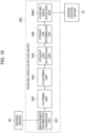
- FIG. 3 is a block diagram illustrating the configuration of the coupling angle detection device 30A.
- the coupling angle detection device 30A is communicatively coupled to the driving control device 10 and the sensor 20.
- the coupling angle detection device 30A includes a measurement information acquisition unit 301, a filtering unit 302, a clustering unit 303, a straight line extraction unit 304, a corner estimation unit 305, and a coupling angle detection unit 306A.
- the measurement information acquisition unit 301 acquires information on the ranging distance to a plurality of measurement points and the ranging direction, by means of the sensor 20, as measurement information regarding each measurement point.
- the filtering unit 302 performs filtering processing for the measurement information by extracting information of the measurement points whose ranging distance is within a prescribed range.
- the clustering unit 303 performs clustering processing to recognize a set of measurement points whose distance from adjacent measurement points is less than a prescribed value, as a measurement point group related to one object.
- the clustering unit 303 calculates the size of each object that is a measurement target, based on the information of the measurement points in the recognized measurement point group. If the calculated size of the object is within a prescribed range corresponding to the target members 40-1 and 40-2, the clustering unit 303 recognizes that the object is the target member 40-1 or 40-2.
- the straight line extraction unit 304 extracts information on the straight line portion as shape information constituting the respective target members 40-1 and 40-2, based on the measurement information on the measurement points corresponding to the respective target members 40-1 and 40-2 which are recognized.
- the corner estimation unit 305 estimates a corner portion which is a corner of each of the target members 40-1 and 40-2, based on the information on the straight line portion extracted by the straight line extraction unit 304.
- the coupling angle detection unit 306A recognizes (determines) the front-rear direction of the vehicle body of the towed vehicle 3, based on the straight line connecting an apex of each corner portion of the target members 40-1 and 40-2 estimated by the corner estimation unit 305.
- the coupling angle detection unit 306A holds information in advance, indicating the front-rear direction of the vehicle body of the towing vehicle 2 with respect to the installation direction of the sensor 20, and detects an angle formed by the front-rear direction of the vehicle body of the towing vehicle 2 as held above and the front-rear direction of the vehicle body of the towed vehicle 3 as recognized above, as a coupling angle of the towing motor vehicle 1A.
- the coupling angle detection unit 306A transmits the information on the detected coupling angle, to the driving control device 10.
- the target members 40-1 and 40-2 have a rectangular shape such as a rectangular parallelepiped.
- the target members 40-1 and 40-2 are installed in the towed vehicle 3 such that each corner in the towing vehicle 2 overlaps a line perpendicular to the front-rear direction of the vehicle body of the towed vehicle 3 on a plane parallel to the traveling surface of the towing motor vehicle 1.
- the sensor 20 measures the distance to a plurality of measurement points in the objects positioned in the upper surface area of the towed vehicle 3, that is, measures the distance to a plurality of measurement points in the objects including the target members 40-1 and 40-2 at prescribed time intervals.
- the sensor 20 measures the distance to a plurality of measurement points, in the target members 40-1 and 40-2 positioned on the upper surface of the towed vehicle 3 and in a projection member 3a that is a portion of the vehicle body, as illustrated in FIG. 2 .
- the sensor 20 may not be able to detect some end portions of the target members 40-1 and 40-2 in the towing vehicle 2 as the measurement target positions.
- the sensor 20 since each of the target members 40-1 and 40-2 is formed of a thick rectangular parallelepiped, the sensor 20 can reliably detect the end portions of the target members 40-1 and 40-2 in the towing vehicle 2 as the measurement target positions.
- the sensor 20 transmits the measurement information regarding a plurality of measurement points in the target members 40-1 and 40-2 and in the projection member 3a, to the coupling angle detection device 30A.
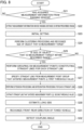
- FIGS. 4A and 4B are flowcharts illustrating a flow of coupling angle detection processing performed when the coupling angle detection device 30A acquires measurement information from the sensor 20.
- the measurement information acquisition unit 301 of the coupling angle detection device 30A acquires the measurement information ("YES" in S1) and transmits such information to the filtering unit 302.
- the filtering unit 302 performs filtering processing for the measurement information by extracting the measurement information whose ranging distance is within a prescribed range (S2). Specifically, the filtering unit 302 extracts the measurement information in which the ranging distance is within a range corresponding to the target members 40-1 and 40-2, among a plurality of measurement points in the target members 40-1 and 40-2 and in the projection member 3a.
- the information in this range is set in advance, in a range in which the probability (reliability) that the measurement points measured by the sensor 20 correspond to the target member 40-1 or 40-2 is equal to or greater than a prescribed value, on the basis of the installation position of the sensor 20 and the installation positions of the target members 40-1 and 40-2.
- the filtering unit 302 determines that the measurement points in the projection member 3a do not correspond to the target members 40-1 and 40-2, and excludes the measurement information of the projection member 3a from the object that is used for the coupling angle detection processing.
- the clustering unit 303 performs clustering processing to recognize a set of measurement points whose distance from adjacent measurement points is less than a prescribed value, as a measurement point group related to one object. Specifically, the clustering unit 303 recognizes the set of measurement points of the identification information P1 to P8 as a measurement point group related to one object, and recognizes the set of measurement points of the identification information P9 to P15 as a measurement point group related to the other object.
- the clustering unit 303 calculates the size of each object that is a measurement target, based on the measurement information regarding the measurement points in each recognized measurement point group (S4).
- the clustering unit 303 holds range information corresponding to the sizes of the target members 40-1 and 40-2 in advance, and recognizes that the object is the target member 40-1 or 40-2 if the calculated size of the object is within a range of the information that is held above.
- the clustering unit 303 recognizes that the sizes of two objects that are measurement targets are within the range of the information that is held in advance, and that these two objects are the target members 40-1 and 40-2 ("YES" in S5).
- the straight line extraction unit 304 extracts measurement point groups constituting straight lines from among the measurement points corresponding to the recognized target members 40-1 and 40-2, and groups the measurement point groups for each straight line (S7). In addition, from among the grouped measurement point groups, the straight line extraction unit 304 extracts a measurement point group whose corresponding measurement points are equal to or greater than a prescribed first threshold value. This first threshold value is a value that is set to determine the reliability of the grouped measurement point group as a straight line portion.
- the straight line extraction unit 304 specifies a straight line from the extracted measurement point group (S7).
- the straight line extraction unit 304 may use, for example, the least squares method when specifying a straight line from the extracted measurement point group.
- the straight line extraction unit 304 extends the straight line to the measurement point. If there is another straight line on an extension line of any of the straight lines which are specified, the straight line extraction unit 304 integrates these straight lines into one straight line (S8). By performing such extension processing and integration processing, the straight line extraction unit 304 can accurately extract the straight line portions of the target members 40-1 and 40-2.
- the straight line extraction unit 304 extracts a straight line whose corresponding measurement points are equal to or greater than a prescribed second threshold value (S9).
- This second threshold value is a value that is set to determine the reliability of the specified straight line as a straight line constituting the outer shape of the target members 40-1 and 40-2.
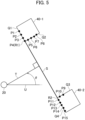
- the corner estimation unit 305 selects the right-downward-sloping line and the right-downward-sloping line for each of the target members 40-1 and 40-2, from the straight lines extracted by the straight line extraction unit 304 (S10 and S11). For example, as illustrated in FIG. 5 , the corner estimation unit 305 selects the straight line Q1 specified by the measurement point groups P1 to P4 as the right-downward-sloping line, and the straight line Q2 specified by the measurement point groups P4 to P8 as the right-upward-sloping line, regarding the target member 40-1.
- the corner estimation unit 305 also selects the straight line Q3 specified by the measurement point groups P9 and P10 as the right-upward-sloping line, and the straight line Q4 specified by the measurement point groups P11 to P15 as the right-downward-sloping line, regarding the target member 40-2.
- the corner estimation unit 305 detects an L-shaped portion where the selected right-downward-sloping line and right-downward-sloping line intersect with each other, regarding each of the target members 40-1 and 40-2.
- the corner estimation unit 305 detects an L-shaped portion corresponding to each of the target members 40-1 and 40-2 ("YES" in S12), the position of the detected L-shaped portion is estimated as a corner portion of each of the target members 40-1 and 40-2 (S13). For example, as illustrated in FIG. 5 , the corner estimation unit 305 estimates the corner portions of the target member 40-1 from the lines Q1 and Q2, and estimates the corner portions of the target member 40-2 from the lines Q3 and Q4.
- the corner estimation unit 305 When the corner estimation unit 305 does not detect the L-shaped portion corresponding to the target member 40-1 or 40-2 in step S12 ("NO" in step S12), the corner estimation unit 305 recognizes the longest straight line from among the straight lines extracted by the line extraction unit 304, as a straight line constituting one target member. The corner estimating unit 305 then estimates one of the end portions of the recognized straight line whose distance from the other target member is shorter, as an apex of the corner portion of one target member (S14).
- the coupling angle detection unit 306A specifies an apex R1 of the corner portion of the target member 40-1, and an apex R2 of the corner portion of the target member 40-2, and further specifies the straight line S connecting these apexes R1 and R2.
- the corner estimation unit 305 specifies the direction T perpendicular to the straight line S, and recognizes (determines) the specified direction T as the front-rear direction of the vehicle body of the towed vehicle 3 (S15).
- the coupling angle detection unit 306A detects an angle ⁇ formed by the recognized front-rear direction T of the vehicle body of the towed vehicle 3 (the specified direction T) and the front-rear direction of the vehicle body of the towing vehicle 2 that is held in advance, as the coupling angle of the towing motor vehicle 1A (S16).
- the coupling angle detection unit 306A outputs the information of the detected coupling angle of the towing motor vehicle 1A, to the driving control device 10.
- the driving control device 10 functions as an automatic driving control unit, and changes the contents of automatic driving by means of the automatic operation control function when detecting that the coupling angle detected by the coupling angle detection unit 30A has reached a prescribed value or more. For example, the driving control device 10 reduces a traveling speed of the vehicle or stops the driving of the vehicle when detecting that the coupling angle has reached a prescribed value or more.
- the driving control device 10 When the towing motor vehicle 1A is a vehicle driven by a driver, the driving control device 10 functions as a notification information output unit, and when detecting that a coupling angle detected by the coupling angle detection device 30A has reached a prescribed value or more, the driving control device 10 outputs information for notifying the driver of the detected contents by means of the notification information output function.
- the shape of the two target members 40-1 and 40-2 installed in the towed vehicle 3 is measured by the sensor 20 installed in the towing vehicle 2 of the towing motor vehicle 1A. Therefore, a coupling angle between the towing vehicle 2 and the towed vehicle 3 can be accurately detected with simple processing. In this case, even if the coupling angle between the towing vehicle 2 and the towed vehicle 3 changes and the distance between the sensor 20 and the target members 40-1 and 40-2 increases, the coupling angle detection processing can be performed with high accuracy without being affected by the increase in the distance, and without requiring the maintenance of the target members 40-1 and 40-2.
- the configuration of the towing motor vehicle 1B according to the second embodiment is similar to the configuration of the towing motor vehicle 1A in FIG. 1 described in the first embodiment, a detailed description of the parts having the same functions will be omitted.
- one target member 40-3 formed of a rectangular parallelepiped is installed at a prescribed position of the towed vehicle 3.
- the coupling angle detection device 30B includes the measurement information acquisition unit 301, the filtering unit 302, the clustering unit 303, the straight line extraction unit 304, a long side estimation unit 307, and a coupling angle detection unit 306B.
- the functions other than those of the long side estimation unit 307 and the coupling angle detection unit 306B are the same as those of the first embodiment, and thus a detailed description thereof will be omitted.
- the long side estimation unit 307 estimates the long side portion of the target member 40-3, based on the information of the straight line portion extracted by the straight line extraction unit 304.
- the coupling angle detection unit 306B specifies the front-rear direction of the vehicle body of the towed vehicle 3, based on the information of the long side portion of the target member 40-3 estimated by the long side estimation unit 307, and further detects the coupling angle of the towing motor vehicle 1B.
- the target member 40-3 is formed of a rectangular parallelepiped.
- the target member 40-3 is installed in the towed vehicle 3 such that the long side in the towing vehicle 2 overlaps a line perpendicular to the front-rear direction of the vehicle body of the towed vehicle 3 on a plane parallel to the traveling surface of the towing motor vehicle 1B.
- the sensor 20 measures the distance to a plurality of measurement points in the object including the target member 40-3 positioned in the upper surface area of the towed vehicle 3 at prescribed time intervals.
- the sensor 20 extracts measurement information regarding the plurality of measurement points in the target member 40-3, and transmits such information to the coupling angle detection device 30B.
- FIG. 8 is a flowchart illustrating a flow of coupling angle detection processing performed when the coupling angle detection device 30B acquires measurement information from the sensor 20. Since the processing of steps S21 to S29 in FIG. 8 is the same as the processing of steps S 1 to S9 described in the first embodiment, a detailed description thereof will be omitted.
- the long side estimation unit 307 estimates the long side portion of the target member 40-3, based on the information on the extracted straight line portion. Specifically, the long side estimation unit 307 estimates (specifies) the longest straight line, as the long side portion of the target member 40-3 (S30).
- the coupling angle detection unit 306B specifies the direction perpendicular to the long side of the target member 40-3, and recognizes (determines) the specified direction as the front-rear direction of the vehicle body of the towed vehicle 3 (S31).
- the coupling angle detection unit 306B detects an angle formed by the front-rear direction of the vehicle body of the towed vehicle 3 that is recognized and the front-rear direction of the vehicle body of the towing vehicle 2 that is held in advance, as an coupling angle of the towing motor vehicle 1B (S32).
- the shape of one target member 40-3 installed in the towed vehicle 3 is measured by the sensor 20 installed in the towing vehicle 2 of the towing motor vehicle 1B. Therefore, a coupling angle between the towing vehicle 2 and the towed vehicle 3 can be accurately detected with simpler processing than that of the first embodiment.
- the configuration of the towing motor vehicle 1C according to the third embodiment is similar to the configuration of the towing motor vehicle 1A in FIG. 1 described in the first embodiment, a detailed description of the parts having the same functions will be omitted.
- one target member 40-4 formed in a rectangular shape close to a cube is installed at a prescribed position of the towed vehicle 3.
- the coupling angle detection device 30C includes the measurement information acquisition unit 301, the filtering unit 302, the clustering unit 303, the straight line extraction unit 304, a straight line determination unit 308, and a coupling angle detection unit 306C.
- the functions other than those of the straight line determination unit 308 and the coupling angle detection unit 306C are the same as those of the first embodiment, and thus a detailed description thereof will be omitted.
- the straight line determination unit 308 determines a straight line portion corresponding to one side of the target member 40-4, based on the information of the straight line portion extracted by the straight line extraction unit 304.
- the coupling angle detection unit 306C specifies the front-rear direction of the vehicle body of the towed vehicle 3, based on the information of the one side portion of the target member 40-4 determined by the straight line determination unit 308, and further detects the coupling angle of the towing motor vehicle 1C.
- the target member 40-4 is formed in a rectangular shape close to a cube.
- the target member 40-4 is installed in the towed vehicle 3 such that one side at the towing vehicle 2 side overlaps a line perpendicular to the front-rear direction of the vehicle body of the towed vehicle 3 on a plane parallel to the traveling surface of the towing motor vehicle 1C.
- the sensor 20 measures the distance to a plurality of measurement points in the object including the target member 40-4 positioned in the upper surface area of the towed vehicle 3 at prescribed time intervals.
- the sensor 20 extracts measurement information regarding the plurality of measurement points in the target member 40-4, and transmits such information to the coupling angle detection device 30C.
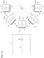
- FIG. 11 is a flowchart illustrating a flow of coupling angle detection processing performed when the coupling angle detection device 30C acquires measurement information from the sensor 20. Since the processing of steps S41 to S49 in FIG. 11 is the same as the processing of steps S1 to S9 described in the first embodiment, a detailed description thereof will be omitted.
- the straight line determination unit 308 determines a straight line portion corresponding to one side of the target member 40-4, based on the information on the extracted straight line portions.
- the processing in which the straight line determination unit 308 determines a straight line portion corresponding to one side of the target member 40-4 will be described below.
- the coupling angle is 0° and the target member 40-4 is in the position (a)
- the side of the target member 40-4 at the towing vehicle 2 side is L1
- the side of the target member 40-4 sequentially arranged in the counterclockwise direction from the side L1 is L2, L3, and L4.
- the straight line in the target member 40-4 measured by the sensor 20 is the side L1.
- the target member 40-4 is, for example, in the position (b) in FIG. 12
- the straight line in the target member 40-4 measured by the sensor 20 is the side L4.
- the target member 40-4 is, for example, in the position (c) in FIG. 12
- the straight line in the target member 40-4 measured by the sensor 20 is the side L3 and the side L4.
- the target member 40-4 When the coupling angle is between about 45° and about 90° in the right direction, the target member 40-4 is, for example, in the position (d) in FIG. 12 , and the straight line in the target member 40-4 measured by the sensor 20 is the side L2. When the coupling angle is about 90° in the right direction, the target member 40-4 is, for example, in the position (e) in FIG. 12 , and the straight line in the target member 40-4 measured by the sensor 20 is the side L3 and the side L2.
- the straight line determination unit 308 holds in advance, information indicating the correspondence relationship between the coupling angle described above, the position of the target member 40-4, and the identification information on the side measured by the sensor 20.
- the straight line determination unit 308 selects, among from the information on the straight line portions extracted by the straight line extraction unit 304, the straight line portion having the longest length, but not the side closest to the coupling mechanism 4 in the target member 40-4.
- the straight line determination unit 308 determines, based on the information that is held, the identification information of one side in the target member 40-4 corresponding to the selected straight line portion, that is, the position of one side in the target member 40-4 and the direction thereof (S50).
- the coupling angle detection unit 306C calculates (specifies) the directions of the sides L2 and L4, based on the identification information of one side in the target member 40-4 and the direction thereof which are determined by the straight line determination unit 308, and recognizes (determines) the calculated direction as the front-rear direction of the vehicle body of the towed vehicle 3 (S51).
- the coupling angle detection unit 306C detects an angle formed by the recognized front-rear direction of the vehicle body of the towed vehicle 3 and the front-rear direction of the vehicle body of the towing vehicle 2 that is held in advance, as an coupling angle of the towing motor vehicle 1C (S52).
- the shape of one target member 40-4 installed in the towed vehicle 3 is measured by the sensor 20 installed in the towing vehicle 2 of the towing motor vehicle 1C. For this reason, a coupling angle between the towing vehicle 2 and the towed vehicle 3 can be accurately detected with simpler processing than that of the first embodiment.
- the target member 40-4 used in the present embodiment has a shape close to a cube. Therefore, unlike the target member 40-3 used in the second embodiment, the space for installing a long object is not required on the towed vehicle 3 thereby increasing the degree of freedom in terms of installation.
- the configuration of the towing motor vehicle 1D according to the fourth embodiment is the same as that of the towing motor vehicle 1A in FIG. 1 described in the first embodiment, a detailed description of the parts having the same functions will be omitted.
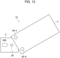
- two target members 40-5 and 40-6 formed in a cylindrical shape are installed at prescribed positions of the towed vehicle 3.
- Three or more cylindrical target members may be installed in the towed vehicle 3.
- the coupling angle detection device 30D includes the measurement information acquisition unit 301, the filtering unit 302, the clustering unit 303, a circle approximation unit 309, and a coupling angle detection unit 306D.
- the functions other than those of the circle approximation unit 309 and the coupling angle detection unit 306D are the same as those of the first embodiment, and thus a detailed description thereof will be omitted.
- the circle approximation unit 309 detects the respective center positions of the circles of the target members 40-5 and 40-6, by performing circle approximation processing using, for example, the least squares method, on the measurement group corresponding to the objects recognized as the target members 40-5 and 40-6 by means of the clustering unit 303.
- the coupling angle detection unit 306D specifies the front-rear direction of the vehicle body of the towed vehicle 3, based on the information of the respective center positions of the circles of the target members 40-5 and 40-6 detected by the circle approximation unit 309, and further detects the coupling angle of the towing motor vehicle 1D.
- the target members 40-5 and 40-6 are formed in a cylindrical shape.
- the target members 40-5 and 40-6 are installed in the towed vehicle 3 such that the respective center positions of the circles overlap a line perpendicular to the front-rear direction of the body of the towed vehicle 3.
- the sensor 20 measures the distance to a plurality of measurement points in the objects including target members 40-5 and 40-6 positioned in the upper surface area of the towed vehicle 3 at prescribed time intervals.
- the sensor 20 extracts measurement information regarding the plurality of measurement points in the target members 40-5 and 40-6, and transmits such information to the coupling angle detection device 30D.
- FIG. 15 is a flowchart illustrating a flow of coupling angle detection processing performed when the coupling angle detection device 30D acquires measurement information from the sensor 20. Since the processing of steps S61 to S65 in FIG. 15 is the same as the processing of steps S1 to S5 described in the first embodiment, a detailed description thereof will be omitted.
- step S66 the circle approximation unit 309 performs circle approximation processing using, for example, the least squares method, on the measurement group corresponding to the target members 40-5 and 40-6 recognized by the clustering unit 303.
- the circle approximation unit 309 detects the respective center positions of the circles of the target members 40-5 and 40-6 (S66).
- the coupling angle detection unit 306D calculates (specifies) a direction perpendicular to the straight line coupling the center positions of the circles detected by the circle approximation unit 309, and recognizes (determines) the calculated direction as the front-rear direction of the vehicle body of the towed vehicle 3 (S67).
- the coupling angle detection unit D detects an angle formed by the recognized front-rear direction of the vehicle body of the towed vehicle 3 and the front-rear direction of the vehicle body of the towing vehicle 2 that is held in advance, as the coupling angle of the towing motor vehicle 1D (S68).
- the shape of two cylindrical target members 40-5 and 40-6 installed in the towed vehicle 3 is measured by the sensor 20 installed in the towing vehicle 2 of the towing motor vehicle 1D. Therefore, the coupling angle between the towing vehicle 2 and the towed vehicle 3 can be accurately detected with simpler processing than that of the first embodiment.
- the configuration of the towing motor vehicle 1E according to the fifth embodiment is the same as that of the towing motor vehicle 1A in FIG. 1 described in the first embodiment, a detailed description of the parts having the same functions will be omitted.
- the shape and number of target members and the position of target members on the towed vehicle 3 are not limited.
- target members, which are installed on the towed vehicle 3, having the same shape and the same number as any of the first to fourth embodiments can be used.
- the coupling angle detection device 30E includes the measurement information acquisition unit 301, the filtering unit 302, a rotation angle calculation unit 310, and a coupling angle detection unit 306E.
- the functions other than those of the rotation angle calculation unit 310 and the coupling angle detection unit 306E are the same as those of the first embodiment, and thus a detailed description thereof will be omitted.
- the rotation angle calculation unit 310 holds in advance, the first shape information which is the shape information of the target member which is acquired, based on the information measured by the sensor 20 when the coupling angle between the towing vehicle 2 and the towed vehicle 3 is 0°.
- the rotation angle calculation unit 310 calculates the rotation angle of the target member corresponding to the position of the sensor 20, based on the shape information of the target member which is held above and the second shape information which is the shape information of the target member which is acquired based on the information measured by the sensor 20 at a given point in time.
- the coupling angle detection unit 306E detects the rotation angle calculated by the rotation angle calculation unit 310 as the coupling angle of the towing motor vehicle 1E at a given point in time.
- the rotation angle calculation unit 310 holds position information on a plurality of measurement point groups in the target member 40-7 measured by the sensor 20 when the coupling angle is 0°, as the shape information of the target member 40-7 in a case where the coupling angle between the towing vehicle 2 and the towed vehicle 3 is 0°.
- the sensor 20 measures the distance to a plurality of measurement points in the object including the target member 40-7 positioned in the upper surface area of the towed vehicle 3 at prescribed time intervals.
- the sensor 20 extracts measurement information regarding the plurality of measurement points in the target member 40-7, and transmits such information to the coupling angle detection device 30E.
- FIG. 17 is a flowchart illustrating a flow of coupling angle detection processing performed when the coupling angle detection device 30E acquires measurement information from the sensor 20. Since the processing of steps S71 and S72 in FIG. 17 is the same as the processing of steps S1 and S2 described in the first embodiment, a detailed description thereof will be omitted.
- step S72 when the filtering unit 302 extracts measurement information whose ranging distance is within a prescribed range through filtering processing, the processing proceeds to step S73.
- step S73 the rotation angle calculation unit 310 calculates the rotation angle between the measurement point groups corresponding to the position of the sensor 20, based on the measurement information extracted by filtering processing and the position information on a plurality of measurement point groups in the target member 40-7 held in advance.
- the rotation angle calculation unit 310 can use an ICP (iterative closest point) algorithm for calculation processing of the rotation angle between the measurement point groups.
- the position of the target member 40-7 when the coupling angle between the towing vehicle 2 and the towed vehicle 3 is 0° is illustrated in (a)
- the position of the target member 40-7 at a given point in time during travelling is illustrated in (b).
- the rotation angle calculation unit 310 calculates the rotation angle ⁇ between the measurement point group when the target member 40-7 is in the position (a) and the measurement point group when the target member 40-7 is in the position (b), based on the position of the sensor 20.
- the coupling angle detection unit 306E detects the rotation angle ⁇ between the measurement point groups calculated by the rotation angle calculation unit 310, as the coupling angle of the towing motor vehicle 1E (S73).
- the sensor 20 installed in the towing vehicle 2 of the towing motor vehicle 1E measures the rotation state of the target member 40-7 installed in the towed vehicle 3. For this reason, the coupling angle between the towing vehicle 2 and the towed vehicle 3 can be accurately detected with simpler processing than that of the first embodiment.
- the target member is installed in the towed vehicle 3 and the sensor 20 is installed in the towing vehicle 2.
- the present disclosure is not limited thereto.
- the target member may be installed in the towing vehicle 2 and the sensor 20 may be installed in the towed vehicle 3 so as to perform the same processing as in the respective embodiments.
Landscapes
- Engineering & Computer Science (AREA)
- Transportation (AREA)
- Mechanical Engineering (AREA)
- Physics & Mathematics (AREA)
- Chemical & Material Sciences (AREA)
- Combustion & Propulsion (AREA)
- Automation & Control Theory (AREA)
- Mathematical Physics (AREA)
- General Physics & Mathematics (AREA)
- Length Measuring Devices With Unspecified Measuring Means (AREA)
Abstract
Description
- The disclosure relates to a coupling angle detection device for a combination vehicle, a combination vehicle, and a coupling angle detection method for a combination vehicle.
- A towing motor vehicle, which is a combination vehicle, is used as a vehicle for carrying containers and other loads in large facilities such as port facilities. A towing motor vehicle is a vehicle in which a towing vehicle (trailer head or tractor) and a towed vehicle (chassis) towed by the towing vehicle are coupled with each other by a coupling mechanism. The coupling mechanism of the towing motor vehicle is configured of a coupler provided in the towing vehicle, and a kingpin provided in the towed vehicle.
- When a towing motor vehicle configured as above travels to turn in the left or right direction, the coupling angle increases. When the coupling angle increases, the vehicle body tends to roll over, and it also becomes difficult for a driver to grasp the movement area of the vehicle body, and thus the driver needs to drive with extra care.
Patent Literature 1 proposes to detect a coupling angle between the towing vehicle and the towed vehicle during the travelling of the towing motor vehicle, and to provide driving assistance based on the detected value. - Patent Literature 1:
Japanese Unexamined Patent Application Publication No. 2002-114176 -
Patent Literature 1 discloses a trailer coupling angle detection device for detecting a coupling angle of a towed vehicle with respect to a towing vehicle by installing a reflector at a prescribed position of the towed vehicle, performing scanning horizontally with respect to the towed vehicle by a scanning radar installed in the towing vehicle, and detecting the direction of reflected light returning from the reflector. - Meanwhile, when using the technology disclosed in
Patent Literature 1, the intensity of reflected light detected by the scanning radar is attenuated when the distance between the scanning radar and the reflector increases due to a change in the installation position of the reflector or the coupling angle of the towed vehicle. Even when dirt adheres to the reflector, the intensity of reflected light detected by the scanning radar decreases. In such cases, the difference between the intensity of reflected light from the reflector and the intensity of reflected light from the surrounding area thereof decreases, and the scanning radar cannot detect reflected light from the reflector in some cases. - An object of the disclosure is to provide a coupling angle detection device for a combination vehicle, a combination vehicle, and a coupling angle detection method for a combination vehicle with which it is possible to accurately detect a coupling angle between two vehicles constituting a combination vehicle with simple processing.
- A coupling angle detection device for a combination vehicle including a first vehicle and a second vehicle coupled to the first vehicle in accordance with an embodiment of the disclosure includes: a target member having a prescribed shape and installed in the first vehicle; a shape information acquisition unit that is installed in the second vehicle and acquires a shape information of the target member; and a coupling angle detection unit that holds in advance, information indicating a front-rear direction of a vehicle body of the second vehicle, recognizes a direction specified based on a prescribed condition from the shape information of the target member acquired by the shape information acquisition unit, as a front-rear direction of a vehicle body of the first vehicle, and detects an angle formed by the front-rear direction of the vehicle body of the second vehicle that is held and the front-rear direction of the vehicle body of the first vehicle that is recognized, as a coupling angle between the first vehicle and the second vehicle. The target member is installed in the first vehicle such that the direction specified based on the prescribed condition from the shape information by the coupling angle detection unit fits the front-rear direction of the vehicle body of the first vehicle.
- The target member may include plural individuals each having a rectangular shape,
the target member may be installed such that each corner of the plural individuals in the second vehicle overlaps a line perpendicular to the front-rear direction of the vehicle body of the first vehicle on a plane parallel to a traveling surface of the first vehicle, and the coupling angle detection unit may detect each of the corners from the shape information of each of the plural individuals and recognize a direction perpendicular to a straight line connecting each of the detected corners as the front-rear direction of the vehicle body of the first vehicle, thereby detecting the coupling angle. - The target member may have a long rectangular shape, the target member may be installed in the first vehicle such that a long side of the target member overlaps a line perpendicular to the front-rear direction of the vehicle body of the first vehicle on a plane parallel to a traveling surface of the first vehicle, and the coupling angle detection unit may detect the long side from the shape information of the target member and recognize a direction perpendicular to the detected long side as the front-rear direction of the vehicle body of the first vehicle, thereby detecting the coupling angle.
- The target member may have a rectangular shape, the target member may be installed in the first vehicle such that one side of the target member overlaps a line perpendicular to the front-rear direction of the vehicle body of the first vehicle on a plane parallel to a traveling surface of the first vehicle, and the coupling angle detection unit may detect the one side from the shape information of the target member and recognize a direction specified based on a position and a direction of the detected one side as the front-rear direction of the vehicle body of the first vehicle, thereby detecting the coupling angle.
- The target member may include plural individuals each having a circular shape, the target member may be installed such that each center position of circles of the plural individuals overlaps a line perpendicular to the front-rear direction of the vehicle body of the first vehicle on a plane parallel to a traveling surface of the first vehicle, and the coupling angle detection unit may detect each center position of the circles from the shape information of each of the plural individuals and recognize a direction perpendicular to a straight line connecting each of the detected center positions as the front-rear direction of the vehicle body of the first vehicle, thereby detecting the coupling angle.
- A coupling angle detection device for a combination vehicle including a first vehicle and a second vehicle coupled to the first vehicle in accordance with an embodiment of the disclosure includes: a target member having a prescribed shape and installed in the first vehicle; a shape information acquisition unit that is installed in the second vehicle and acquires a shape information of the target member; a rotation angle calculation unit that holds in advance, the shape information of the target member acquired by the shape information acquisition unit when a coupling angle between the first vehicle and the second vehicle is 0°, as a first shape information, acquires the shape information of the target member acquired by the shape information acquisition unit at a given point in time as a second shape information, and calculates a rotation angle between the first shape information and the second shape information based on a position of the shape information acquisition unit; and a coupling angle detection unit that detects a rotation angle calculated by the rotation angle calculation unit, as a coupling angle between the first vehicle and the second vehicle at the given point in time.
- A combination vehicle in accordance with an embodiment of the disclosure includes: the coupling angle detection device for a combination vehicle above; and an automatic driving control unit that causes an own vehicle to drive automatically, and changes contents of automatic driving when the coupling angle detected by the coupling angle detection unit has reached a prescribed value or more.
- A combination vehicle in accordance with an embodiment of the disclosure includes: the coupling angle detection device for a combination vehicle above; and a notification information output unit that outputs information for notifying a driver that the coupling angle of an own vehicle has reached a prescribed value or more when detecting that the coupling angle detected by the coupling angle detection device has reached a prescribed value or more.
- A coupling angle detection method for a combination vehicle in accordance with an embodiment of the disclosure is a method for the combination vehicle including a first vehicle in which a target member having a prescribed shape is installed and a second vehicle coupled to the first vehicle and in which a shape information acquisition unit that acquires a shape information of the target member is installed, the combination vehicle in which the target member is installed such that a direction specified based on a prescribed condition from the shape information fits a front-rear direction of a vehicle body of the first vehicle. The coupling angle detection method for the combination vehicle includes: holding in advance, information indicating a front-rear direction of a vehicle body of the second vehicle; recognizing a direction specified based on the prescribed condition from the shape information of the target member acquired by the shape information acquisition unit, as a front-rear direction of a vehicle body of the first vehicle; and detecting an angle formed by the front-rear direction of the vehicle body of the second vehicle that is held and the front-rear direction of the vehicle body of the first vehicle that is recognized, as a coupling angle between the first vehicle and the second vehicle.
- According to the disclosure, it is possible to accurately detect a coupling angle between two vehicles constituting a combination vehicle with simple processing.
-
- [
FIG. 1] FIG. 1 is a side view illustrating a configuration of a towing motor vehicle in which a coupling angle detection device according to a first embodiment is installed. - [
FIG. 2] FIG. 2 is a top view of the towing motor vehicle in which the coupling angle detection device according to the first embodiment is installed. - [
FIG. 3] FIG. 3 is a block diagram illustrating a configuration of the coupling angle detection device according to the first embodiment. - [
FIG. 4A] FIG. 4A is a flowchart illustrating a flow of coupling angle detection processing performed by the coupling angle detection device according to the first embodiment. - [
FIG. 4B] FIG. 4B is a flowchart illustrating a flow of the coupling angle detection processing performed by the coupling angle detection device according to the first embodiment. - [
FIG. 5] FIG. 5 is an explanatory diagram illustrating measurement points in target members measured by asensor 20 connected to the coupling angle detection device according to the first embodiment, and a coupling angle that is detected based on the measurement point information. - [
FIG. 6] FIG. 6 is a top view of a towing motor vehicle in which a coupling angle detection device according to a second embodiment is installed. - [
FIG. 7] FIG. 7 is a block diagram illustrating a configuration of the coupling angle detection device according to the second embodiment. - [
FIG. 8] FIG. 8 is a flowchart illustrating a flow of coupling angle detection processing performed by the coupling angle detection device according to the second embodiment. - [
FIG. 9] FIG. 9 is a top view of a towing motor vehicle in which a coupling angle detection device according to a third embodiment is installed. - [
FIG. 10] FIG. 10 is a block diagram illustrating a configuration of the coupling angle detection device according to the third embodiment. - [
FIG. 11] FIG. 11 is a flowchart illustrating a flow of coupling angle detection processing performed by the coupling angle detection device according to the third embodiment. - [
FIG. 12] FIG. 12 is an explanatory diagram illustrating measurement points in a target member, which is measured by asensor 20 connected to the coupling angle detection device according to the third embodiment, for each coupling angle. - [
FIG. 13] FIG. 13 is a top view of a towing motor vehicle in which a coupling angle detection device according to a fourth embodiment is installed. - [
FIG. 14] FIG. 14 is a block diagram illustrating a configuration of the coupling angle detection device according to the fourth embodiment. - [
FIG. 15] FIG. 15 is a flowchart illustrating a flow of coupling angle detection processing performed by the coupling angle detection device according to the fourth embodiment. - [
FIG. 16] FIG. 16 is a block diagram illustrating a configuration of a coupling angle detection device according to a fifth embodiment. - [
FIG. 17] FIG. 17 is a flowchart illustrating a flow of coupling angle detection processing performed by the coupling angle detection device according to the fifth embodiment. - [
FIG. 18] FIG. 18 is an explanatory diagram illustrating a coupling angle detected by the coupling angle detection device according to the fifth embodiment. - Some embodiments of a coupling angle detection device for detecting a coupling angle of a towing motor vehicle, which is a combination vehicle, will be described below with reference to the drawings. A towing motor vehicle is a vehicle in which a towing vehicle (trailer head or tractor) and a towed vehicle (chassis) towed by the towing vehicle are coupled with each other by a coupling mechanism. The coupling mechanism of the towing motor vehicle is configured of a coupler provided in the towing vehicle, and a kingpin provided in the towed vehicle, and the coupling angle (the coupling angle between the towing vehicle and the towed vehicle) changes due to a change in the traveling direction of the towing motor vehicle or the like.
-
FIG. 1 is a side view illustrating a configuration of atowing motor vehicle 1A using a couplingangle detection device 30A according to the first embodiment. Thetowing motor vehicle 1A includes atowing vehicle 2, a towedvehicle 3, and acoupling mechanism 4 for coupling thetowing vehicle 2 and thetowed vehicle 3. A plurality of target members 40-1 and 40-2 are installed at prescribed positions of thetowed vehicle 3 serving as the first vehicle. These target members 40-1 and 40-2 are installed in thetowed vehicle 3 such that the direction specified based on the prescribed condition from the shape information thereof fits the front-rear direction of the vehicle body of thetowed vehicle 3. In the present embodiment, as illustrated inFIG. 2 , two identically shaped target members 40-1 and 40-2 are installed at prescribed positions on the upper surface of the towedvehicle 3. The installation positions of the target members 40-1 and 40-2 in the towedvehicle 3 will be described later. - The towing
vehicle 2 serving as a second vehicle is provided with a drivingcontrol device 10, asensor 20 as a shape information acquisition device, and a couplingangle detection device 30A. - The driving
control device 10 controls the driving of the towingvehicle 2. Thesensor 20 is configured of, for example, a camera device or a LiDAR (light detection and ranging). Thesensor 20 is installed at a prescribed position in the rear of the towingvehicle 2, and measures the distance to a plurality of positions in the objects positioned in the upper surface area of the towedvehicle 3 behind the towingvehicle 2. Hereinafter, the position to be measured by thesensor 20 is described as a measurement point. -
FIG. 3 is a block diagram illustrating the configuration of the couplingangle detection device 30A. The couplingangle detection device 30A is communicatively coupled to the drivingcontrol device 10 and thesensor 20. The coupling angle detection device 30Aincludes a measurementinformation acquisition unit 301, afiltering unit 302, aclustering unit 303, a straightline extraction unit 304, acorner estimation unit 305, and a couplingangle detection unit 306A. - The measurement
information acquisition unit 301 acquires information on the ranging distance to a plurality of measurement points and the ranging direction, by means of thesensor 20, as measurement information regarding each measurement point. Of the measurement points corresponding to the measurement information acquired by the measurementinformation acquisition unit 301, thefiltering unit 302 performs filtering processing for the measurement information by extracting information of the measurement points whose ranging distance is within a prescribed range. - Regarding the information of the measurement points performed by the
filtering unit 302, theclustering unit 303 performs clustering processing to recognize a set of measurement points whose distance from adjacent measurement points is less than a prescribed value, as a measurement point group related to one object. Theclustering unit 303 calculates the size of each object that is a measurement target, based on the information of the measurement points in the recognized measurement point group. If the calculated size of the object is within a prescribed range corresponding to the target members 40-1 and 40-2, theclustering unit 303 recognizes that the object is the target member 40-1 or 40-2. - The straight
line extraction unit 304 extracts information on the straight line portion as shape information constituting the respective target members 40-1 and 40-2, based on the measurement information on the measurement points corresponding to the respective target members 40-1 and 40-2 which are recognized. Thecorner estimation unit 305 estimates a corner portion which is a corner of each of the target members 40-1 and 40-2, based on the information on the straight line portion extracted by the straightline extraction unit 304. - The coupling
angle detection unit 306A recognizes (determines) the front-rear direction of the vehicle body of the towedvehicle 3, based on the straight line connecting an apex of each corner portion of the target members 40-1 and 40-2 estimated by thecorner estimation unit 305. The couplingangle detection unit 306A holds information in advance, indicating the front-rear direction of the vehicle body of the towingvehicle 2 with respect to the installation direction of thesensor 20, and detects an angle formed by the front-rear direction of the vehicle body of the towingvehicle 2 as held above and the front-rear direction of the vehicle body of the towedvehicle 3 as recognized above, as a coupling angle of the towingmotor vehicle 1A. The couplingangle detection unit 306A transmits the information on the detected coupling angle, to the drivingcontrol device 10. - The operation of the towing
motor vehicle 1A using the couplingangle detection device 30A according to the present embodiment will be described below. In the present embodiment, the target members 40-1 and 40-2 have a rectangular shape such as a rectangular parallelepiped. The target members 40-1 and 40-2 are installed in the towedvehicle 3 such that each corner in the towingvehicle 2 overlaps a line perpendicular to the front-rear direction of the vehicle body of the towedvehicle 3 on a plane parallel to the traveling surface of the towingmotor vehicle 1. - During traveling of the towing
motor vehicle 1A, thesensor 20 measures the distance to a plurality of measurement points in the objects positioned in the upper surface area of the towedvehicle 3, that is, measures the distance to a plurality of measurement points in the objects including the target members 40-1 and 40-2 at prescribed time intervals. In the present embodiment, thesensor 20 measures the distance to a plurality of measurement points, in the target members 40-1 and 40-2 positioned on the upper surface of the towedvehicle 3 and in aprojection member 3a that is a portion of the vehicle body, as illustrated inFIG. 2 . - At this time, if the target members 40-1 and 40-2 are formed of thin plate-like members, depending on the coupling angle between the towing
vehicle 2 and the towedvehicle 3, thesensor 20 may not be able to detect some end portions of the target members 40-1 and 40-2 in the towingvehicle 2 as the measurement target positions. However, in the present embodiment, since each of the target members 40-1 and 40-2 is formed of a thick rectangular parallelepiped, thesensor 20 can reliably detect the end portions of the target members 40-1 and 40-2 in the towingvehicle 2 as the measurement target positions. Thesensor 20 transmits the measurement information regarding a plurality of measurement points in the target members 40-1 and 40-2 and in theprojection member 3a, to the couplingangle detection device 30A. -
FIGS. 4A and4B are flowcharts illustrating a flow of coupling angle detection processing performed when the couplingangle detection device 30A acquires measurement information from thesensor 20. When measurement information is transmitted from thesensor 20, the measurementinformation acquisition unit 301 of the couplingangle detection device 30A acquires the measurement information ("YES" in S1) and transmits such information to thefiltering unit 302. - Of the measurement information regarding the respective measurement points acquired by the measurement
information acquisition unit 301, thefiltering unit 302 performs filtering processing for the measurement information by extracting the measurement information whose ranging distance is within a prescribed range (S2). Specifically, thefiltering unit 302 extracts the measurement information in which the ranging distance is within a range corresponding to the target members 40-1 and 40-2, among a plurality of measurement points in the target members 40-1 and 40-2 and in theprojection member 3a. The information in this range is set in advance, in a range in which the probability (reliability) that the measurement points measured by thesensor 20 correspond to the target member 40-1 or 40-2 is equal to or greater than a prescribed value, on the basis of the installation position of thesensor 20 and the installation positions of the target members 40-1 and 40-2. In this filtering processing, thefiltering unit 302 determines that the measurement points in theprojection member 3a do not correspond to the target members 40-1 and 40-2, and excludes the measurement information of theprojection member 3a from the object that is used for the coupling angle detection processing. - Next, the
clustering unit 303 performs an initial setting by giving identification information to the respective measurement points extracted by filtering processing (S3). Specifically, as illustrated inFIG. 5 , theclustering unit 303 gives identification information P1, identification information P2, ... identification information P15, to the fifteen measurement points, respectively. - Next, regarding the measurement points extracted by filtering processing, the
clustering unit 303 performs clustering processing to recognize a set of measurement points whose distance from adjacent measurement points is less than a prescribed value, as a measurement point group related to one object. Specifically, theclustering unit 303 recognizes the set of measurement points of the identification information P1 to P8 as a measurement point group related to one object, and recognizes the set of measurement points of the identification information P9 to P15 as a measurement point group related to the other object. - The
clustering unit 303 calculates the size of each object that is a measurement target, based on the measurement information regarding the measurement points in each recognized measurement point group (S4). Theclustering unit 303 holds range information corresponding to the sizes of the target members 40-1 and 40-2 in advance, and recognizes that the object is the target member 40-1 or 40-2 if the calculated size of the object is within a range of the information that is held above. Here, theclustering unit 303 recognizes that the sizes of two objects that are measurement targets are within the range of the information that is held in advance, and that these two objects are the target members 40-1 and 40-2 ("YES" in S5). - Next, the straight
line extraction unit 304 extracts measurement point groups constituting straight lines from among the measurement points corresponding to the recognized target members 40-1 and 40-2, and groups the measurement point groups for each straight line (S7). In addition, from among the grouped measurement point groups, the straightline extraction unit 304 extracts a measurement point group whose corresponding measurement points are equal to or greater than a prescribed first threshold value. This first threshold value is a value that is set to determine the reliability of the grouped measurement point group as a straight line portion. The straightline extraction unit 304 specifies a straight line from the extracted measurement point group (S7). Here, the straightline extraction unit 304 may use, for example, the least squares method when specifying a straight line from the extracted measurement point group. - Next, if there is a measurement point that does not belong to any of the straight line measurement point groups on an extension line of any of the straight lines specified for the respective target members 40-1 and 40-2, the straight
line extraction unit 304 extends the straight line to the measurement point. If there is another straight line on an extension line of any of the straight lines which are specified, the straightline extraction unit 304 integrates these straight lines into one straight line (S8). By performing such extension processing and integration processing, the straightline extraction unit 304 can accurately extract the straight line portions of the target members 40-1 and 40-2. - Next, from among the extracted straight lines, the straight
line extraction unit 304 extracts a straight line whose corresponding measurement points are equal to or greater than a prescribed second threshold value (S9). This second threshold value is a value that is set to determine the reliability of the specified straight line as a straight line constituting the outer shape of the target members 40-1 and 40-2. - Next, the
corner estimation unit 305 selects the right-downward-sloping line and the right-downward-sloping line for each of the target members 40-1 and 40-2, from the straight lines extracted by the straight line extraction unit 304 (S10 and S11). For example, as illustrated inFIG. 5 , thecorner estimation unit 305 selects the straight line Q1 specified by the measurement point groups P1 to P4 as the right-downward-sloping line, and the straight line Q2 specified by the measurement point groups P4 to P8 as the right-upward-sloping line, regarding the target member 40-1. Thecorner estimation unit 305 also selects the straight line Q3 specified by the measurement point groups P9 and P10 as the right-upward-sloping line, and the straight line Q4 specified by the measurement point groups P11 to P15 as the right-downward-sloping line, regarding the target member 40-2. - Thereafter, the
corner estimation unit 305 detects an L-shaped portion where the selected right-downward-sloping line and right-downward-sloping line intersect with each other, regarding each of the target members 40-1 and 40-2. - Next, when the
corner estimation unit 305 detects an L-shaped portion corresponding to each of the target members 40-1 and 40-2 ("YES" in S12), the position of the detected L-shaped portion is estimated as a corner portion of each of the target members 40-1 and 40-2 (S13). For example, as illustrated inFIG. 5 , thecorner estimation unit 305 estimates the corner portions of the target member 40-1 from the lines Q1 and Q2, and estimates the corner portions of the target member 40-2 from the lines Q3 and Q4. - When the
corner estimation unit 305 does not detect the L-shaped portion corresponding to the target member 40-1 or 40-2 in step S12 ("NO" in step S12), thecorner estimation unit 305 recognizes the longest straight line from among the straight lines extracted by theline extraction unit 304, as a straight line constituting one target member. Thecorner estimating unit 305 then estimates one of the end portions of the recognized straight line whose distance from the other target member is shorter, as an apex of the corner portion of one target member (S14). - Next, the coupling
angle detection unit 306A specifies an apex R1 of the corner portion of the target member 40-1, and an apex R2 of the corner portion of the target member 40-2, and further specifies the straight line S connecting these apexes R1 and R2. Thecorner estimation unit 305 then specifies the direction T perpendicular to the straight line S, and recognizes (determines) the specified direction T as the front-rear direction of the vehicle body of the towed vehicle 3 (S15). - Next, the coupling
angle detection unit 306A detects an angle θ formed by the recognized front-rear direction T of the vehicle body of the towed vehicle 3 (the specified direction T) and the front-rear direction of the vehicle body of the towingvehicle 2 that is held in advance, as the coupling angle of the towingmotor vehicle 1A (S16). The couplingangle detection unit 306A outputs the information of the detected coupling angle of the towingmotor vehicle 1A, to the drivingcontrol device 10. - When the towing
motor vehicle 1A is an automatic driving vehicle, the drivingcontrol device 10 functions as an automatic driving control unit, and changes the contents of automatic driving by means of the automatic operation control function when detecting that the coupling angle detected by the couplingangle detection unit 30A has reached a prescribed value or more. For example, the drivingcontrol device 10 reduces a traveling speed of the vehicle or stops the driving of the vehicle when detecting that the coupling angle has reached a prescribed value or more. - By performing the driving control in this manner, it is possible to ensure safe traveling when the towing
motor vehicle 1A performing the automatic driving turns in the right or left direction and a coupling angle thereof increases. - When the towing
motor vehicle 1A is a vehicle driven by a driver, the drivingcontrol device 10 functions as a notification information output unit, and when detecting that a coupling angle detected by the couplingangle detection device 30A has reached a prescribed value or more, the drivingcontrol device 10 outputs information for notifying the driver of the detected contents by means of the notification information output function. - By outputting the information in this manner, it is possible to alert the driver when the towing
motor vehicle 1A driven by the driver turns in the right or left direction and a coupling angle thereof increases, thereby supporting safe driving. - According to the first embodiment, the shape of the two target members 40-1 and 40-2 installed in the towed
vehicle 3 is measured by thesensor 20 installed in the towingvehicle 2 of the towingmotor vehicle 1A. Therefore, a coupling angle between the towingvehicle 2 and the towedvehicle 3 can be accurately detected with simple processing. In this case, even if the coupling angle between the towingvehicle 2 and the towedvehicle 3 changes and the distance between thesensor 20 and the target members 40-1 and 40-2 increases, the coupling angle detection processing can be performed with high accuracy without being affected by the increase in the distance, and without requiring the maintenance of the target members 40-1 and 40-2. - Since the configuration of the towing
motor vehicle 1B according to the second embodiment is similar to the configuration of the towingmotor vehicle 1A inFIG. 1 described in the first embodiment, a detailed description of the parts having the same functions will be omitted. In the present embodiment, as illustrated inFIG. 6 , one target member 40-3 formed of a rectangular parallelepiped is installed at a prescribed position of the towedvehicle 3. - As illustrated in
FIG. 7 , the couplingangle detection device 30B according to the present embodiment includes the measurementinformation acquisition unit 301, thefiltering unit 302, theclustering unit 303, the straightline extraction unit 304, a longside estimation unit 307, and a couplingangle detection unit 306B. The functions other than those of the longside estimation unit 307 and the couplingangle detection unit 306B are the same as those of the first embodiment, and thus a detailed description thereof will be omitted. - The long
side estimation unit 307 estimates the long side portion of the target member 40-3, based on the information of the straight line portion extracted by the straightline extraction unit 304. The couplingangle detection unit 306B specifies the front-rear direction of the vehicle body of the towedvehicle 3, based on the information of the long side portion of the target member 40-3 estimated by the longside estimation unit 307, and further detects the coupling angle of the towingmotor vehicle 1B. - The operation of the towing
motor vehicle 1B using the couplingangle detection device 30B according to the present embodiment will be described below. In the present embodiment, the target member 40-3 is formed of a rectangular parallelepiped. The target member 40-3 is installed in the towedvehicle 3 such that the long side in the towingvehicle 2 overlaps a line perpendicular to the front-rear direction of the vehicle body of the towedvehicle 3 on a plane parallel to the traveling surface of the towingmotor vehicle 1B. - During traveling of the towing
motor vehicle 1B, thesensor 20 measures the distance to a plurality of measurement points in the object including the target member 40-3 positioned in the upper surface area of the towedvehicle 3 at prescribed time intervals. Thesensor 20 extracts measurement information regarding the plurality of measurement points in the target member 40-3, and transmits such information to the couplingangle detection device 30B. -
FIG. 8 is a flowchart illustrating a flow of coupling angle detection processing performed when the couplingangle detection device 30B acquires measurement information from thesensor 20. Since the processing of steps S21 to S29 inFIG. 8 is the same as the processing of steps S 1 to S9 described in the first embodiment, a detailed description thereof will be omitted. - When the straight
line extraction unit 304 extracts a straight line portion of the object on the towedvehicle 3 in step S29, based on the measurement information measured by thesensor 20, the longside estimation unit 307 estimates the long side portion of the target member 40-3, based on the information on the extracted straight line portion. Specifically, the longside estimation unit 307 estimates (specifies) the longest straight line, as the long side portion of the target member 40-3 (S30). - Next, the coupling
angle detection unit 306B specifies the direction perpendicular to the long side of the target member 40-3, and recognizes (determines) the specified direction as the front-rear direction of the vehicle body of the towed vehicle 3 (S31). The couplingangle detection unit 306B then detects an angle formed by the front-rear direction of the vehicle body of the towedvehicle 3 that is recognized and the front-rear direction of the vehicle body of the towingvehicle 2 that is held in advance, as an coupling angle of the towingmotor vehicle 1B (S32). - According to the second embodiment, the shape of one target member 40-3 installed in the towed
vehicle 3 is measured by thesensor 20 installed in the towingvehicle 2 of the towingmotor vehicle 1B. Therefore, a coupling angle between the towingvehicle 2 and the towedvehicle 3 can be accurately detected with simpler processing than that of the first embodiment. - Since the configuration of the towing
motor vehicle 1C according to the third embodiment is similar to the configuration of the towingmotor vehicle 1A inFIG. 1 described in the first embodiment, a detailed description of the parts having the same functions will be omitted. In the present embodiment, as illustrated inFIG. 9 , one target member 40-4 formed in a rectangular shape close to a cube is installed at a prescribed position of the towedvehicle 3. - As illustrated in
FIG. 10 , the couplingangle detection device 30C according to the present embodiment includes the measurementinformation acquisition unit 301, thefiltering unit 302, theclustering unit 303, the straightline extraction unit 304, a straightline determination unit 308, and a couplingangle detection unit 306C. The functions other than those of the straightline determination unit 308 and the couplingangle detection unit 306C are the same as those of the first embodiment, and thus a detailed description thereof will be omitted. - The straight
line determination unit 308 determines a straight line portion corresponding to one side of the target member 40-4, based on the information of the straight line portion extracted by the straightline extraction unit 304. The couplingangle detection unit 306C specifies the front-rear direction of the vehicle body of the towedvehicle 3, based on the information of the one side portion of the target member 40-4 determined by the straightline determination unit 308, and further detects the coupling angle of the towingmotor vehicle 1C. - The operation of the towing
motor vehicle 1C using the couplingangle detection device 30C according to the present embodiment will be described. In the present embodiment, the target member 40-4 is formed in a rectangular shape close to a cube. The target member 40-4 is installed in the towedvehicle 3 such that one side at the towingvehicle 2 side overlaps a line perpendicular to the front-rear direction of the vehicle body of the towedvehicle 3 on a plane parallel to the traveling surface of the towingmotor vehicle 1C. - During traveling of the towing
motor vehicle 1C, thesensor 20 measures the distance to a plurality of measurement points in the object including the target member 40-4 positioned in the upper surface area of the towedvehicle 3 at prescribed time intervals. Thesensor 20 extracts measurement information regarding the plurality of measurement points in the target member 40-4, and transmits such information to the couplingangle detection device 30C. -
FIG. 11 is a flowchart illustrating a flow of coupling angle detection processing performed when the couplingangle detection device 30C acquires measurement information from thesensor 20. Since the processing of steps S41 to S49 inFIG. 11 is the same as the processing of steps S1 to S9 described in the first embodiment, a detailed description thereof will be omitted. - When the straight
line extraction unit 304 extracts straight line portions of the object on the towedvehicle 3 in step S49, based on the measurement information measured by thesensor 20, the straightline determination unit 308 determines a straight line portion corresponding to one side of the target member 40-4, based on the information on the extracted straight line portions. The processing in which the straightline determination unit 308 determines a straight line portion corresponding to one side of the target member 40-4 will be described below. - As illustrated in
FIG. 12 , when the coupling angle is 0° and the target member 40-4 is in the position (a), the side of the target member 40-4 at the towingvehicle 2 side is L1, and the side of the target member 40-4 sequentially arranged in the counterclockwise direction from the side L1 is L2, L3, and L4. - Here, when the coupling angle is between 0° and about 45° in the left-right direction, the straight line in the target member 40-4 measured by the
sensor 20 is the side L1. When the coupling angle is between about 45° and about 90° in the left direction, the target member 40-4 is, for example, in the position (b) inFIG. 12 , and the straight line in the target member 40-4 measured by thesensor 20 is the side L4. When the coupling angle is about 90° in the left direction, the target member 40-4 is, for example, in the position (c) inFIG. 12 , and the straight line in the target member 40-4 measured by thesensor 20 is the side L3 and the side L4. When the coupling angle is between about 45° and about 90° in the right direction, the target member 40-4 is, for example, in the position (d) inFIG. 12 , and the straight line in the target member 40-4 measured by thesensor 20 is the side L2. When the coupling angle is about 90° in the right direction, the target member 40-4 is, for example, in the position (e) inFIG. 12 , and the straight line in the target member 40-4 measured by thesensor 20 is the side L3 and the side L2. - The straight
line determination unit 308 holds in advance, information indicating the correspondence relationship between the coupling angle described above, the position of the target member 40-4, and the identification information on the side measured by thesensor 20. The straightline determination unit 308 then selects, among from the information on the straight line portions extracted by the straightline extraction unit 304, the straight line portion having the longest length, but not the side closest to thecoupling mechanism 4 in the target member 40-4. Next, the straightline determination unit 308 determines, based on the information that is held, the identification information of one side in the target member 40-4 corresponding to the selected straight line portion, that is, the position of one side in the target member 40-4 and the direction thereof (S50). - Next, the coupling
angle detection unit 306C calculates (specifies) the directions of the sides L2 and L4, based on the identification information of one side in the target member 40-4 and the direction thereof which are determined by the straightline determination unit 308, and recognizes (determines) the calculated direction as the front-rear direction of the vehicle body of the towed vehicle 3 (S51). The couplingangle detection unit 306C then detects an angle formed by the recognized front-rear direction of the vehicle body of the towedvehicle 3 and the front-rear direction of the vehicle body of the towingvehicle 2 that is held in advance, as an coupling angle of the towingmotor vehicle 1C (S52). - According to the third embodiment, the shape of one target member 40-4 installed in the towed
vehicle 3 is measured by thesensor 20 installed in the towingvehicle 2 of the towingmotor vehicle 1C. For this reason, a coupling angle between the towingvehicle 2 and the towedvehicle 3 can be accurately detected with simpler processing than that of the first embodiment. In addition, the target member 40-4 used in the present embodiment has a shape close to a cube. Therefore, unlike the target member 40-3 used in the second embodiment, the space for installing a long object is not required on the towedvehicle 3 thereby increasing the degree of freedom in terms of installation. - Since the configuration of the towing
motor vehicle 1D according to the fourth embodiment is the same as that of the towingmotor vehicle 1A inFIG. 1 described in the first embodiment, a detailed description of the parts having the same functions will be omitted. In the present embodiment, as illustrated inFIG. 13 , two target members 40-5 and 40-6 formed in a cylindrical shape are installed at prescribed positions of the towedvehicle 3. Three or more cylindrical target members may be installed in the towedvehicle 3. - As illustrated in
FIG. 14 , the couplingangle detection device 30D according to the present embodiment includes the measurementinformation acquisition unit 301, thefiltering unit 302, theclustering unit 303, acircle approximation unit 309, and a couplingangle detection unit 306D. The functions other than those of thecircle approximation unit 309 and the couplingangle detection unit 306D are the same as those of the first embodiment, and thus a detailed description thereof will be omitted. - The
circle approximation unit 309 detects the respective center positions of the circles of the target members 40-5 and 40-6, by performing circle approximation processing using, for example, the least squares method, on the measurement group corresponding to the objects recognized as the target members 40-5 and 40-6 by means of theclustering unit 303. The couplingangle detection unit 306D specifies the front-rear direction of the vehicle body of the towedvehicle 3, based on the information of the respective center positions of the circles of the target members 40-5 and 40-6 detected by thecircle approximation unit 309, and further detects the coupling angle of the towingmotor vehicle 1D. - The operation of the towing
motor vehicle 1D using the couplingangle detection device 30D according to the present embodiment will be described below. In the present embodiment, the target members 40-5 and 40-6 are formed in a cylindrical shape. The target members 40-5 and 40-6 are installed in the towedvehicle 3 such that the respective center positions of the circles overlap a line perpendicular to the front-rear direction of the body of the towedvehicle 3. - During traveling of the towing
motor vehicle 1D, thesensor 20 measures the distance to a plurality of measurement points in the objects including target members 40-5 and 40-6 positioned in the upper surface area of the towedvehicle 3 at prescribed time intervals. Thesensor 20 extracts measurement information regarding the plurality of measurement points in the target members 40-5 and 40-6, and transmits such information to the couplingangle detection device 30D. -
FIG. 15 is a flowchart illustrating a flow of coupling angle detection processing performed when the couplingangle detection device 30D acquires measurement information from thesensor 20. Since the processing of steps S61 to S65 inFIG. 15 is the same as the processing of steps S1 to S5 described in the first embodiment, a detailed description thereof will be omitted. - When the
clustering unit 303 recognizes that the sizes of two objects that are measurement targets are within the range of the information that is held in advance, and that these two objects are the target members 40-5 and 40-6 ("YES" in S65), the processing proceeds to step S66. In step S66, thecircle approximation unit 309 performs circle approximation processing using, for example, the least squares method, on the measurement group corresponding to the target members 40-5 and 40-6 recognized by theclustering unit 303. Thecircle approximation unit 309 then detects the respective center positions of the circles of the target members 40-5 and 40-6 (S66). - Next, the coupling
angle detection unit 306D calculates (specifies) a direction perpendicular to the straight line coupling the center positions of the circles detected by thecircle approximation unit 309, and recognizes (determines) the calculated direction as the front-rear direction of the vehicle body of the towed vehicle 3 (S67). The coupling angle detection unit D then detects an angle formed by the recognized front-rear direction of the vehicle body of the towedvehicle 3 and the front-rear direction of the vehicle body of the towingvehicle 2 that is held in advance, as the coupling angle of the towingmotor vehicle 1D (S68). - According to the fourth embodiment, the shape of two cylindrical target members 40-5 and 40-6 installed in the towed
vehicle 3 is measured by thesensor 20 installed in the towingvehicle 2 of the towingmotor vehicle 1D. Therefore, the coupling angle between the towingvehicle 2 and the towedvehicle 3 can be accurately detected with simpler processing than that of the first embodiment. - Since the configuration of the towing
motor vehicle 1E according to the fifth embodiment is the same as that of the towingmotor vehicle 1A inFIG. 1 described in the first embodiment, a detailed description of the parts having the same functions will be omitted. In the present embodiment, the shape and number of target members and the position of target members on the towedvehicle 3 are not limited. For example, target members, which are installed on the towedvehicle 3, having the same shape and the same number as any of the first to fourth embodiments can be used. - As illustrated in
FIG. 16 , the couplingangle detection device 30E according to the present embodiment includes the measurementinformation acquisition unit 301, thefiltering unit 302, a rotationangle calculation unit 310, and a couplingangle detection unit 306E. The functions other than those of the rotationangle calculation unit 310 and the couplingangle detection unit 306E are the same as those of the first embodiment, and thus a detailed description thereof will be omitted. - The rotation
angle calculation unit 310 holds in advance, the first shape information which is the shape information of the target member which is acquired, based on the information measured by thesensor 20 when the coupling angle between the towingvehicle 2 and the towedvehicle 3 is 0°. The rotationangle calculation unit 310 calculates the rotation angle of the target member corresponding to the position of thesensor 20, based on the shape information of the target member which is held above and the second shape information which is the shape information of the target member which is acquired based on the information measured by thesensor 20 at a given point in time. - The coupling
angle detection unit 306E detects the rotation angle calculated by the rotationangle calculation unit 310 as the coupling angle of the towingmotor vehicle 1E at a given point in time. - The operation of the towing
motor vehicle 1E using the couplingangle detection device 30E according to the present embodiment will be described. As an example, a case will be described in which one target member 40-7 formed in a rectangular shape is installed on the towedvehicle 3. In the present embodiment, the rotationangle calculation unit 310 holds position information on a plurality of measurement point groups in the target member 40-7 measured by thesensor 20 when the coupling angle is 0°, as the shape information of the target member 40-7 in a case where the coupling angle between the towingvehicle 2 and the towedvehicle 3 is 0°. - During traveling of the towed
motor vehicle 1E, thesensor 20 measures the distance to a plurality of measurement points in the object including the target member 40-7 positioned in the upper surface area of the towedvehicle 3 at prescribed time intervals. Thesensor 20 extracts measurement information regarding the plurality of measurement points in the target member 40-7, and transmits such information to the couplingangle detection device 30E. -
FIG. 17 is a flowchart illustrating a flow of coupling angle detection processing performed when the couplingangle detection device 30E acquires measurement information from thesensor 20. Since the processing of steps S71 and S72 inFIG. 17 is the same as the processing of steps S1 and S2 described in the first embodiment, a detailed description thereof will be omitted. - In step S72, when the
filtering unit 302 extracts measurement information whose ranging distance is within a prescribed range through filtering processing, the processing proceeds to step S73. In step S73, the rotationangle calculation unit 310 calculates the rotation angle between the measurement point groups corresponding to the position of thesensor 20, based on the measurement information extracted by filtering processing and the position information on a plurality of measurement point groups in the target member 40-7 held in advance. For example, the rotationangle calculation unit 310 can use an ICP (iterative closest point) algorithm for calculation processing of the rotation angle between the measurement point groups. - In
FIG. 18 , the position of the target member 40-7 when the coupling angle between the towingvehicle 2 and the towedvehicle 3 is 0° is illustrated in (a), and the position of the target member 40-7 at a given point in time during travelling is illustrated in (b). At this time, the rotationangle calculation unit 310 calculates the rotation angle θ between the measurement point group when the target member 40-7 is in the position (a) and the measurement point group when the target member 40-7 is in the position (b), based on the position of thesensor 20. - Next, the coupling
angle detection unit 306E detects the rotation angle θ between the measurement point groups calculated by the rotationangle calculation unit 310, as the coupling angle of the towingmotor vehicle 1E (S73). - According to the fifth embodiment, the
sensor 20 installed in the towingvehicle 2 of the towingmotor vehicle 1E measures the rotation state of the target member 40-7 installed in the towedvehicle 3. For this reason, the coupling angle between the towingvehicle 2 and the towedvehicle 3 can be accurately detected with simpler processing than that of the first embodiment. - In the first to fifth embodiments described above, the case has been described in which the target member is installed in the towed
vehicle 3 and thesensor 20 is installed in the towingvehicle 2. However, the present disclosure is not limited thereto. For example, the target member may be installed in the towingvehicle 2 and thesensor 20 may be installed in the towedvehicle 3 so as to perform the same processing as in the respective embodiments. - Although some embodiments have been described, the embodiments may be changed or modified based on the above disclosure. All of the components of the above embodiments and all of the features described within the scope of the claims may be extracted and combined individually, provided they are not mutually inconsistent.
- The entire contents of
Japanese Patent Application No. 2021-187020 (filing date: November 17, 2021 -
- 1A, 1B, 1C, 1D, 1E towing motor vehicle (combination vehicle)
- 2 towing vehicle (second vehicle or first vehicle)
- 3 towed vehicle (first vehicle or second vehicle)
- 10 driving control device (automatic driving control unit, notification information output unit)
- 20 sensor (shape information acquisition device)
- 30A, 30B, 30C, 30D, 30E coupling angle detection device
- 40-1 to 40-7 target member
- 306A, 306B, 306C, 306D, 306E coupling angle detection unit
- 310 rotation angle calculation unit
Claims (9)
- A coupling angle detection device for a combination vehicle including a first vehicle and a second vehicle coupled to the first vehicle, the coupling angle detection device comprising:a target member having a prescribed shape and installed in the first vehicle;a shape information acquisition unit installed in the second vehicle and configured to acquire a shape information of the target member; anda coupling angle detection unit configured to hold in advance, information indicating a front-rear direction of a vehicle body of the second vehicle, recognize a direction specified based on a prescribed condition from the shape information of the target member acquired by the shape information acquisition unit, as a front-rear direction of a vehicle body of the first vehicle, and detect an angle formed by the front-rear direction of the vehicle body of the second vehicle that is held and the front-rear direction of the vehicle body of the first vehicle that is recognized, as a coupling angle between the first vehicle and the second vehicle,wherein the target member is installed in the first vehicle such that the direction specified based on the prescribed condition from the shape information by means of the coupling angle detection unit fits the front-rear direction of the vehicle body of the first vehicle.
- The coupling angle detection device for a combination vehicle according to claim 1, whereinthe target member includes plural individuals each having a rectangular shape,the target member is installed such that each corner of the plural individuals in the second vehicle overlaps a line perpendicular to the front-rear direction of the vehicle body of the first vehicle on a plane parallel to a traveling surface of the first vehicle, andthe coupling angle detection unit is configured to detect each of the corners from the shape information of each of the plural individuals and recognize a direction perpendicular to a straight line connecting each of the detected corners as the front-rear direction of the vehicle body of the first vehicle, thereby detecting the coupling angle.
- The coupling angle detection device for a combination vehicle according to claim 1, whereinthe target member has a long rectangular shape,the target member is installed in the first vehicle such that a long side of the target member overlaps a line perpendicular to the front-rear direction of the vehicle body of the first vehicle on a plane parallel to a traveling surface of the first vehicle, andthe coupling angle detection unit is configured to detect the long side from the shape information of the target member and recognize a direction perpendicular to the detected long side as the front-rear direction of the vehicle body of the first vehicle, thereby detecting the coupling angle.
- The coupling angle detection device for a combination vehicle according to claim 1, whereinthe target member has a rectangular shape,the target member is installed in the first vehicle such that one side of the target member overlaps a line perpendicular to the front-rear direction of the vehicle body of the first vehicle on a plane parallel to a traveling surface of the first vehicle, andthe coupling angle detection unit is configured to detect the one side from the shape information of the target member and recognize a direction specified based on a position and a direction of the detected one side as the front-rear direction of the vehicle body of the first vehicle, thereby detecting the coupling angle.
- The coupling angle detection device for a combination vehicle according to claim 1, whereinthe target member includes plural individuals each having a circular shape,the target member is installed such that each center position of circles of the plural individuals overlaps a line perpendicular to the front-rear direction of the vehicle body of the first vehicle on a plane parallel to a traveling surface of the first vehicle, andthe coupling angle detection unit is configured to detect each center position of the circles from the shape information of each of the plural individuals and recognize a direction perpendicular to a straight line connecting each of the detected center positions as the front-rear direction of the vehicle body of the first vehicle, thereby detecting the coupling angle.
- A coupling angle detection device for a combination vehicle including a first vehicle and a second vehicle coupled to the first vehicle, the coupling angle detection device comprising:a target member having a prescribed shape and installed in the first vehicle;a shape information acquisition unit installed in the second vehicle and configured to acquire a shape information of the target member;a rotation angle calculation unit configured to hold in advance, the shape information of the target member acquired by the shape information acquisition unit when a coupling angle between the first vehicle and the second vehicle is 0°, as a first shape information, acquire the shape information of the target member acquired by the shape information acquisition unit at a given point in time as a second shape information, and calculate a rotation angle between the first shape information and the second shape information based on a position of the shape information acquisition unit; anda coupling angle detection unit configured to detect a rotation angle calculated by the rotation angle calculation unit, as a coupling angle between the first vehicle and the second vehicle at the given point in time.
- A combination vehicle comprising:a coupling angle detection device for a combination vehicle according to any one of claims 1 to 6; andan automatic driving control unit configured to cause an own vehicle to drive automatically, and change contents of automatic driving when the coupling angle detected by the coupling angle detection unit has reached a prescribed value or more.
- A combination vehicle comprising:a coupling angle detection device for a combination vehicle according to any one of claims 1 to 6; anda notification information output unit configured to output information for notifying a driver that the coupling angle of an own vehicle has reached a prescribed value or more when detecting that the coupling angle detected by the coupling angle detection device has reached a prescribed value or more.
- A coupling angle detection method for a combination vehicle including a first vehicle in which a target member having a prescribed shape is installed and a second vehicle coupled to the first vehicle and in which a shape information acquisition unit configured to acquire a shape information of the target member is installed, the combination vehicle in which the target member is installed such that a direction specified based on a prescribed condition from the shape information fits a front-rear direction of a vehicle body of the first vehicle, the method comprising:holding in advance, information indicating a front-rear direction of a vehicle body of the second vehicle;recognizing a direction specified based on the prescribed condition from the shape information of the target member acquired by the shape information acquisition unit, as a front-rear direction of a vehicle body of the first vehicle; anddetecting an angle formed by the front-rear direction of the vehicle body of the second vehicle that is held and the front-rear direction of the vehicle body of the first vehicle that is recognized, as a coupling angle between the first vehicle and the second vehicle.
Applications Claiming Priority (2)
| Application Number | Priority Date | Filing Date | Title |
|---|---|---|---|
| JP2021187020 | 2021-11-17 | ||
| PCT/JP2022/040327 WO2023090122A1 (en) | 2021-11-17 | 2022-10-28 | Connection angle detection apparatus for combination vehicle, combination vehicle, and method for detecting connection angle of combination vehicle |
Publications (2)
| Publication Number | Publication Date |
|---|---|
| EP4435378A1 true EP4435378A1 (en) | 2024-09-25 |
| EP4435378A4 EP4435378A4 (en) | 2026-01-21 |
Family
ID=86396760
Family Applications (1)
| Application Number | Title | Priority Date | Filing Date |
|---|---|---|---|
| EP22895405.3A Pending EP4435378A4 (en) | 2021-11-17 | 2022-10-28 | Connection angle detection device for a combination vehicle, combination vehicle and method for detecting the connection angle of a combination vehicle |
Country Status (6)
| Country | Link |
|---|---|
| US (1) | US12491892B2 (en) |
| EP (1) | EP4435378A4 (en) |
| JP (1) | JP7708207B2 (en) |
| KR (1) | KR20240093602A (en) |
| CN (1) | CN118159803A (en) |
| WO (1) | WO2023090122A1 (en) |
Families Citing this family (1)
| Publication number | Priority date | Publication date | Assignee | Title |
|---|---|---|---|---|
| DE102023131347A1 (en) * | 2023-11-10 | 2025-05-15 | Mekra Lang Gmbh & Co. Kg | Camera-based system and method for determining the position of a trailer |
Family Cites Families (17)
| Publication number | Priority date | Publication date | Assignee | Title |
|---|---|---|---|---|
| JP2001334966A (en) * | 2000-03-24 | 2001-12-04 | Isuzu Motors Ltd | Trailer connection angle detection device |
| JP3716722B2 (en) * | 2000-08-24 | 2005-11-16 | いすゞ自動車株式会社 | Trailer connection angle detector |
| JP2002114176A (en) | 2000-10-11 | 2002-04-16 | Isuzu Motors Ltd | Trailer connection angle detection device |
| JP3643076B2 (en) * | 2001-11-15 | 2005-04-27 | 日野自動車株式会社 | Connecting angle detector |
| GB2447672B (en) | 2007-03-21 | 2011-12-14 | Ford Global Tech Llc | Vehicle manoeuvring aids |
| US9085261B2 (en) * | 2011-01-26 | 2015-07-21 | Magna Electronics Inc. | Rear vision system with trailer angle detection |
| US9437055B2 (en) | 2014-08-13 | 2016-09-06 | Bendix Commercial Vehicle Systems Llc | Cabin and trailer body movement determination with camera at the back of the cabin |
| KR20160041445A (en) * | 2014-10-07 | 2016-04-18 | 현대모비스 주식회사 | Trailer Track Estimation Method and System by Image Recognition |
| JP6448029B2 (en) * | 2015-01-27 | 2019-01-09 | 日野自動車株式会社 | Connecting angle acquisition device for connected vehicle and driving support system for connected vehicle |
| DE102016211396B4 (en) * | 2016-06-24 | 2024-05-08 | Zf Friedrichshafen Ag | Autonomous coupling of a trailer |
| JP7023788B2 (en) * | 2018-05-16 | 2022-02-22 | フォルシアクラリオン・エレクトロニクス株式会社 | Tow support device |
| JP7081305B2 (en) | 2018-05-24 | 2022-06-07 | 株式会社アイシン | Peripheral monitoring device |
| US11125881B2 (en) * | 2018-12-10 | 2021-09-21 | Waymo Llc | Lidar-based trailer tracking |
| EP3678096B1 (en) * | 2019-01-07 | 2021-06-23 | Continental Automotive GmbH | Method for calculating a tow hitch position |
| JP2021187020A (en) | 2020-05-28 | 2021-12-13 | 三菱電機株式会社 | Injection molding mold, injection molding apparatus, and resin molding method |
| CN111578893A (en) * | 2020-05-29 | 2020-08-25 | 苏州挚途科技有限公司 | Method for identifying included angle between tractor and trailer |
| US11598870B2 (en) * | 2021-03-09 | 2023-03-07 | GM Global Technology Operations LLC | Methods, systems, and apparatuses to estimate hitch articulation angle (HAA) using ultra-sonic sensors (USS) and fusion with other sensors |
-
2022
- 2022-10-28 EP EP22895405.3A patent/EP4435378A4/en active Pending
- 2022-10-28 CN CN202280071421.6A patent/CN118159803A/en active Pending
- 2022-10-28 JP JP2023561503A patent/JP7708207B2/en active Active
- 2022-10-28 KR KR1020247016113A patent/KR20240093602A/en not_active Ceased
- 2022-10-28 WO PCT/JP2022/040327 patent/WO2023090122A1/en not_active Ceased
-
2024
- 2024-04-23 US US18/643,266 patent/US12491892B2/en active Active
Also Published As
| Publication number | Publication date |
|---|---|
| WO2023090122A1 (en) | 2023-05-25 |
| JP7708207B2 (en) | 2025-07-15 |
| EP4435378A4 (en) | 2026-01-21 |
| JPWO2023090122A1 (en) | 2023-05-25 |
| CN118159803A (en) | 2024-06-07 |
| KR20240093602A (en) | 2024-06-24 |
| US20240270259A1 (en) | 2024-08-15 |
| US12491892B2 (en) | 2025-12-09 |
Similar Documents
| Publication | Publication Date | Title |
|---|---|---|
| US11707999B2 (en) | Camera based auto drive auto charge | |
| US10353065B2 (en) | Method for detecting a mark made on a ground, driver assistance device and motor vehicle | |
| US10977504B2 (en) | Vehicle-mounted image target objection recognition device | |
| CN109923491B (en) | Sensor arrangement for an autonomously operating commercial vehicle and method for looking around image sensing | |
| CN107179530B (en) | Device for ascertaining the offset of a detection device mounted on a vehicle | |
| US9656691B2 (en) | Method for performing an at least semi-autonomous parking process of a motor vehicle in a garage, parking assistance system and motor vehicle | |
| CN109219546B (en) | Parking assist device and parking assist method | |
| US10685567B2 (en) | Method for determining a parking area for parking a motor vehicle, driver assistance system and motor vehicle | |
| CN111028534B (en) | Parking space detection method and device | |
| JP7020353B2 (en) | Object detector | |
| US20140292542A1 (en) | Method for classifying parking scenarios for a system for parking a motor vehicle | |
| US20170262716A1 (en) | Object recognition apparatus | |
| KR102937581B1 (en) | A method for evaluating the effect of objects surrounding a vehicle on its operation. | |
| CN103847667A (en) | Vehicle driving support control apparatus | |
| US20150046015A1 (en) | Method and Device for Assisting in Returning a Vehicle After Leaving a Roadway | |
| CN113650607A (en) | Automatic driving method and system for low-speed scene and automobile | |
| US20180350108A1 (en) | Smart Hitch Assistant System | |
| EP3035315B1 (en) | Information retrieval arrangement | |
| EP4435378A1 (en) | Connection angle detection apparatus for combination vehicle, combination vehicle, and method for detecting connection angle of combination vehicle | |
| CN110834635B (en) | Automatic driving method and control system for hydrogen energy automobile merging scene | |
| JP5103722B2 (en) | Stop vehicle discrimination device | |
| CN115257790B (en) | Sensor abnormality estimation device | |
| US20190354781A1 (en) | Method and system for determining an object location by using map information | |
| CN112026700A (en) | Automobile anti-collision early warning method and system and storage medium | |
| EP4282726B1 (en) | Air drag model estimation using visual information |
Legal Events
| Date | Code | Title | Description |
|---|---|---|---|
| STAA | Information on the status of an ep patent application or granted ep patent |
Free format text: STATUS: THE INTERNATIONAL PUBLICATION HAS BEEN MADE |
|
| PUAI | Public reference made under article 153(3) epc to a published international application that has entered the european phase |
Free format text: ORIGINAL CODE: 0009012 |
|
| STAA | Information on the status of an ep patent application or granted ep patent |
Free format text: STATUS: REQUEST FOR EXAMINATION WAS MADE |
|
| 17P | Request for examination filed |
Effective date: 20240430 |
|
| AK | Designated contracting states |
Kind code of ref document: A1 Designated state(s): AL AT BE BG CH CY CZ DE DK EE ES FI FR GB GR HR HU IE IS IT LI LT LU LV MC ME MK MT NL NO PL PT RO RS SE SI SK SM TR |
|
| DAV | Request for validation of the european patent (deleted) | ||
| DAX | Request for extension of the european patent (deleted) | ||
| A4 | Supplementary search report drawn up and despatched |
Effective date: 20251223 |
|
| RIC1 | Information provided on ipc code assigned before grant |
Ipc: G01B 11/26 20060101AFI20251217BHEP Ipc: B62D 13/00 20060101ALI20251217BHEP Ipc: B62D 53/00 20060101ALI20251217BHEP Ipc: B60D 1/62 20060101ALI20251217BHEP |