EP4435356A1 - Refrigerator - Google Patents
Refrigerator Download PDFInfo
- Publication number
- EP4435356A1 EP4435356A1 EP22894689.3A EP22894689A EP4435356A1 EP 4435356 A1 EP4435356 A1 EP 4435356A1 EP 22894689 A EP22894689 A EP 22894689A EP 4435356 A1 EP4435356 A1 EP 4435356A1
- Authority
- EP
- European Patent Office
- Prior art keywords
- pipe
- door
- cabinet
- flexible
- intake
- Prior art date
- Legal status (The legal status is an assumption and is not a legal conclusion. Google has not performed a legal analysis and makes no representation as to the accuracy of the status listed.)
- Pending
Links
- 238000009413 insulation Methods 0.000 claims abstract description 53
- 238000005057 refrigeration Methods 0.000 claims abstract description 27
- 238000010438 heat treatment Methods 0.000 claims abstract description 25
- RYGMFSIKBFXOCR-UHFFFAOYSA-N Copper Chemical compound [Cu] RYGMFSIKBFXOCR-UHFFFAOYSA-N 0.000 claims description 86
- 229910052802 copper Inorganic materials 0.000 claims description 86
- 239000010949 copper Substances 0.000 claims description 86
- 230000004308 accommodation Effects 0.000 claims description 20
- 230000008014 freezing Effects 0.000 claims description 4
- 238000007710 freezing Methods 0.000 claims description 4
- 238000009833 condensation Methods 0.000 description 20
- 239000003507 refrigerant Substances 0.000 description 18
- 239000012530 fluid Substances 0.000 description 16
- 230000005494 condensation Effects 0.000 description 15
- 238000004519 manufacturing process Methods 0.000 description 13
- 238000009434 installation Methods 0.000 description 8
- 230000000694 effects Effects 0.000 description 5
- XLYOFNOQVPJJNP-UHFFFAOYSA-N water Substances O XLYOFNOQVPJJNP-UHFFFAOYSA-N 0.000 description 4
- 239000006260 foam Substances 0.000 description 3
- 238000000034 method Methods 0.000 description 3
- 239000002937 thermal insulation foam Substances 0.000 description 3
- 238000010586 diagram Methods 0.000 description 2
- 230000000149 penetrating effect Effects 0.000 description 2
- 239000000853 adhesive Substances 0.000 description 1
- 230000001070 adhesive effect Effects 0.000 description 1
- 230000006835 compression Effects 0.000 description 1
- 238000007906 compression Methods 0.000 description 1
- 230000002708 enhancing effect Effects 0.000 description 1
- 239000006261 foam material Substances 0.000 description 1
- 238000011900 installation process Methods 0.000 description 1
- 239000012774 insulation material Substances 0.000 description 1
- 230000013011 mating Effects 0.000 description 1
- 239000002184 metal Substances 0.000 description 1
- 229910052751 metal Inorganic materials 0.000 description 1
- 238000007789 sealing Methods 0.000 description 1
- 239000008400 supply water Substances 0.000 description 1
Images




Classifications
-
- F—MECHANICAL ENGINEERING; LIGHTING; HEATING; WEAPONS; BLASTING
- F25—REFRIGERATION OR COOLING; COMBINED HEATING AND REFRIGERATION SYSTEMS; HEAT PUMP SYSTEMS; MANUFACTURE OR STORAGE OF ICE; LIQUEFACTION SOLIDIFICATION OF GASES
- F25D—REFRIGERATORS; COLD ROOMS; ICE-BOXES; COOLING OR FREEZING APPARATUS NOT OTHERWISE PROVIDED FOR
- F25D11/00—Self-contained movable devices, e.g. domestic refrigerators
- F25D11/02—Self-contained movable devices, e.g. domestic refrigerators with cooling compartments at different temperatures
-
- F—MECHANICAL ENGINEERING; LIGHTING; HEATING; WEAPONS; BLASTING
- F25—REFRIGERATION OR COOLING; COMBINED HEATING AND REFRIGERATION SYSTEMS; HEAT PUMP SYSTEMS; MANUFACTURE OR STORAGE OF ICE; LIQUEFACTION SOLIDIFICATION OF GASES
- F25C—PRODUCING, WORKING OR HANDLING ICE
- F25C5/00—Working or handling ice
- F25C5/20—Distributing ice
- F25C5/22—Distributing ice particularly adapted for household refrigerators
-
- F—MECHANICAL ENGINEERING; LIGHTING; HEATING; WEAPONS; BLASTING
- F25—REFRIGERATION OR COOLING; COMBINED HEATING AND REFRIGERATION SYSTEMS; HEAT PUMP SYSTEMS; MANUFACTURE OR STORAGE OF ICE; LIQUEFACTION SOLIDIFICATION OF GASES
- F25D—REFRIGERATORS; COLD ROOMS; ICE-BOXES; COOLING OR FREEZING APPARATUS NOT OTHERWISE PROVIDED FOR
- F25D17/00—Arrangements for circulating cooling fluids; Arrangements for circulating gas, e.g. air, within refrigerated spaces
- F25D17/04—Arrangements for circulating cooling fluids; Arrangements for circulating gas, e.g. air, within refrigerated spaces for circulating air, e.g. by convection
- F25D17/06—Arrangements for circulating cooling fluids; Arrangements for circulating gas, e.g. air, within refrigerated spaces for circulating air, e.g. by convection by forced circulation
- F25D17/062—Arrangements for circulating cooling fluids; Arrangements for circulating gas, e.g. air, within refrigerated spaces for circulating air, e.g. by convection by forced circulation in household refrigerators
- F25D17/065—Arrangements for circulating cooling fluids; Arrangements for circulating gas, e.g. air, within refrigerated spaces for circulating air, e.g. by convection by forced circulation in household refrigerators with compartments at different temperatures
-
- F—MECHANICAL ENGINEERING; LIGHTING; HEATING; WEAPONS; BLASTING
- F25—REFRIGERATION OR COOLING; COMBINED HEATING AND REFRIGERATION SYSTEMS; HEAT PUMP SYSTEMS; MANUFACTURE OR STORAGE OF ICE; LIQUEFACTION SOLIDIFICATION OF GASES
- F25D—REFRIGERATORS; COLD ROOMS; ICE-BOXES; COOLING OR FREEZING APPARATUS NOT OTHERWISE PROVIDED FOR
- F25D21/00—Defrosting; Preventing frosting; Removing condensed or defrost water
- F25D21/04—Preventing the formation of frost or condensate
-
- F—MECHANICAL ENGINEERING; LIGHTING; HEATING; WEAPONS; BLASTING
- F25—REFRIGERATION OR COOLING; COMBINED HEATING AND REFRIGERATION SYSTEMS; HEAT PUMP SYSTEMS; MANUFACTURE OR STORAGE OF ICE; LIQUEFACTION SOLIDIFICATION OF GASES
- F25D—REFRIGERATORS; COLD ROOMS; ICE-BOXES; COOLING OR FREEZING APPARATUS NOT OTHERWISE PROVIDED FOR
- F25D23/00—General constructional features
- F25D23/006—General constructional features for mounting refrigerating machinery components
-
- F—MECHANICAL ENGINEERING; LIGHTING; HEATING; WEAPONS; BLASTING
- F25—REFRIGERATION OR COOLING; COMBINED HEATING AND REFRIGERATION SYSTEMS; HEAT PUMP SYSTEMS; MANUFACTURE OR STORAGE OF ICE; LIQUEFACTION SOLIDIFICATION OF GASES
- F25D—REFRIGERATORS; COLD ROOMS; ICE-BOXES; COOLING OR FREEZING APPARATUS NOT OTHERWISE PROVIDED FOR
- F25D23/00—General constructional features
- F25D23/02—Doors; Covers
-
- F—MECHANICAL ENGINEERING; LIGHTING; HEATING; WEAPONS; BLASTING
- F25—REFRIGERATION OR COOLING; COMBINED HEATING AND REFRIGERATION SYSTEMS; HEAT PUMP SYSTEMS; MANUFACTURE OR STORAGE OF ICE; LIQUEFACTION SOLIDIFICATION OF GASES
- F25D—REFRIGERATORS; COLD ROOMS; ICE-BOXES; COOLING OR FREEZING APPARATUS NOT OTHERWISE PROVIDED FOR
- F25D23/00—General constructional features
- F25D23/02—Doors; Covers
- F25D23/028—Details
-
- F—MECHANICAL ENGINEERING; LIGHTING; HEATING; WEAPONS; BLASTING
- F25—REFRIGERATION OR COOLING; COMBINED HEATING AND REFRIGERATION SYSTEMS; HEAT PUMP SYSTEMS; MANUFACTURE OR STORAGE OF ICE; LIQUEFACTION SOLIDIFICATION OF GASES
- F25D—REFRIGERATORS; COLD ROOMS; ICE-BOXES; COOLING OR FREEZING APPARATUS NOT OTHERWISE PROVIDED FOR
- F25D23/00—General constructional features
- F25D23/06—Walls
- F25D23/061—Walls with conduit means
-
- F—MECHANICAL ENGINEERING; LIGHTING; HEATING; WEAPONS; BLASTING
- F25—REFRIGERATION OR COOLING; COMBINED HEATING AND REFRIGERATION SYSTEMS; HEAT PUMP SYSTEMS; MANUFACTURE OR STORAGE OF ICE; LIQUEFACTION SOLIDIFICATION OF GASES
- F25D—REFRIGERATORS; COLD ROOMS; ICE-BOXES; COOLING OR FREEZING APPARATUS NOT OTHERWISE PROVIDED FOR
- F25D23/00—General constructional features
- F25D23/12—Arrangements of compartments additional to cooling compartments; Combinations of refrigerators with other equipment, e.g. stove
-
- F—MECHANICAL ENGINEERING; LIGHTING; HEATING; WEAPONS; BLASTING
- F25—REFRIGERATION OR COOLING; COMBINED HEATING AND REFRIGERATION SYSTEMS; HEAT PUMP SYSTEMS; MANUFACTURE OR STORAGE OF ICE; LIQUEFACTION SOLIDIFICATION OF GASES
- F25D—REFRIGERATORS; COLD ROOMS; ICE-BOXES; COOLING OR FREEZING APPARATUS NOT OTHERWISE PROVIDED FOR
- F25D2317/00—Details or arrangements for circulating cooling fluids; Details or arrangements for circulating gas, e.g. air, within refrigerated spaces, not provided for in other groups of this subclass
- F25D2317/06—Details or arrangements for circulating cooling fluids; Details or arrangements for circulating gas, e.g. air, within refrigerated spaces, not provided for in other groups of this subclass with forced air circulation
- F25D2317/062—Details or arrangements for circulating cooling fluids; Details or arrangements for circulating gas, e.g. air, within refrigerated spaces, not provided for in other groups of this subclass with forced air circulation along the inside of doors
-
- F—MECHANICAL ENGINEERING; LIGHTING; HEATING; WEAPONS; BLASTING
- F25—REFRIGERATION OR COOLING; COMBINED HEATING AND REFRIGERATION SYSTEMS; HEAT PUMP SYSTEMS; MANUFACTURE OR STORAGE OF ICE; LIQUEFACTION SOLIDIFICATION OF GASES
- F25D—REFRIGERATORS; COLD ROOMS; ICE-BOXES; COOLING OR FREEZING APPARATUS NOT OTHERWISE PROVIDED FOR
- F25D2317/00—Details or arrangements for circulating cooling fluids; Details or arrangements for circulating gas, e.g. air, within refrigerated spaces, not provided for in other groups of this subclass
- F25D2317/06—Details or arrangements for circulating cooling fluids; Details or arrangements for circulating gas, e.g. air, within refrigerated spaces, not provided for in other groups of this subclass with forced air circulation
- F25D2317/065—Details or arrangements for circulating cooling fluids; Details or arrangements for circulating gas, e.g. air, within refrigerated spaces, not provided for in other groups of this subclass with forced air circulation characterised by the air return
-
- F—MECHANICAL ENGINEERING; LIGHTING; HEATING; WEAPONS; BLASTING
- F25—REFRIGERATION OR COOLING; COMBINED HEATING AND REFRIGERATION SYSTEMS; HEAT PUMP SYSTEMS; MANUFACTURE OR STORAGE OF ICE; LIQUEFACTION SOLIDIFICATION OF GASES
- F25D—REFRIGERATORS; COLD ROOMS; ICE-BOXES; COOLING OR FREEZING APPARATUS NOT OTHERWISE PROVIDED FOR
- F25D2323/00—General constructional features not provided for in other groups of this subclass
- F25D2323/02—Details of doors or covers not otherwise covered
- F25D2323/024—Door hinges
-
- F—MECHANICAL ENGINEERING; LIGHTING; HEATING; WEAPONS; BLASTING
- F25—REFRIGERATION OR COOLING; COMBINED HEATING AND REFRIGERATION SYSTEMS; HEAT PUMP SYSTEMS; MANUFACTURE OR STORAGE OF ICE; LIQUEFACTION SOLIDIFICATION OF GASES
- F25D—REFRIGERATORS; COLD ROOMS; ICE-BOXES; COOLING OR FREEZING APPARATUS NOT OTHERWISE PROVIDED FOR
- F25D2400/00—General features of, or devices for refrigerators, cold rooms, ice-boxes, or for cooling or freezing apparatus not covered by any other subclass
- F25D2400/02—Refrigerators including a heater
Definitions
- This application relates to the field of home appliances, particularly to a refrigerator.
- some refrigerators have an ice-making compartment provided on a refrigeration door, the ice-making compartment is equipped with an ice-making device and an independent ice-making evaporator that supplies cold air to the ice-making compartment.
- the compressor and condenser are often located in the compressor compartment on a cabinet side.
- the ice-making evaporator is connected to the compressor via a return pipe, the return pipe passes out of the hinge axis of the refrigeration door and enters the thermal insulation layer of the cabinet.
- condensation occurs due to the low temperature of the refrigerant in the return pipe and the exposure of the return pipe between the refrigeration door and the cabinet.
- a foam insulation tube is generally sleeved over the return pipe to prevent condensation, but the foam insulation tube is large in volume, inconvenient to pass through the hinge axis, occupies a large space, affects the aesthetics, and is easily damaged.
- the present application proposes a refrigerator that can prevent condensation on the return pipe between the cabinet and the door.
- a refrigerator comprising:
- the heating wire comprises multiple resistance wires arranged at intervals along the circumference of the return pipe.
- the wall of the flexible return pipe is embedded with a heating wire that is equal in length to the flexible return pipe.
- the refrigeration system further comprises a door capillary tube, which is located on the door side and positioned between the condenser and the door evaporator.
- the cabinet comprises an outer shell and an inner liner
- the thermal insulation layer is located between the outer shell and the inner liner
- the inner liner forms a storage compartment
- the cabinet side is provided with a compressor compartment for installing the compressor
- the return pipe comprises a flexible return pipe and a return copper pipe
- the flexible return pipe passes out of the hinge axis on the door side, passes through the thermal insulation layer of the cabinet from the pipe port, and enters the compressor compartment to connect with the return copper pipe.
- the intake pipe comprises a flexible intake pipe and an intake copper pipe
- the flexible intake pipe passes out of the hinge axis on the door side, passes through the thermal insulation layer of the cabinet from the pipe port, and enters the compressor compartment to connect with the intake copper pipe.
- the cabinet side is provided with a compressor compartment for installing the compressor
- the return pipe comprises a flexible return pipe and a return copper pipe
- the return copper pipe passes through the thermal insulation layer of the cabinet from the compressor compartment and passes out from the pipe port
- the flexible return pipe extends from the hinge axis to the cabinet side and connects with the return copper pipe.
- the intake pipe comprises an flexible intake pipe and an intake copper pipe
- the intake copper pipe passes through the thermal insulation layer of the cabinet from the compressor compartment and passes out from the pipe port
- the intake copper pipe extends from the hinge axis on the door side to the cabinet side and connects with the intake copper pipe
- the cabinet is provided with a pipe accommodation groove and a thermal insulation cover that closes the pipe accommodation groove
- the pipe port is located in the pipe accommodation groove
- an interface between the flexible intake pipe and the intake copper pipe and an interface between the flexible return pipe and the return copper pipe are located in the pipe accommodation groove.
- a storage compartment formed inside the cabinet comprises a refrigeration compartment and a freezing compartment
- a refrigeration door for opening and closing the refrigeration compartment is provided with an ice-making compartment
- the door evaporator is located inside the ice-making compartment.
- the refrigerator provided by the present application embeds a heating wire directly in a wall of the flexible return pipe between the door and the cabinet, which can solve the condensation problem of the exposed flexible return pipe between the door and the cabinet.
- the heating wire is directly embedded in the wall of the flexible return pipe, with a compact overall structure, occupying less space, and convenient for installation and manufacturing.
- the heating wire is not directly exposed on the outside, and the wall of the flexible return pipe can protect the heating wire, ensuring high safety. Additionally, the good toughness of the heating wire can increase the toughness of the flexible return pipe without damaging its lifespan.
- refrigerator 100 comprises a cabinet 110 and a door 120 for opening and closing the cabinet 110.
- the door 120 can be pivotally connected to the cabinet 110 via a hinge 130, the hinge 130 has a hinge plate fixedly connected to the cabinet 110 and a hinge axis 132 pivotally connected to the door 120.
- the door 110 is provided with a door axis, and the hinge axis 132 is connected to the door axis, so that the door can rotate relative to the cabinet.
- Both the cabinet 110 and the door 120 can be provided with thermal insulation layers to prevent the loss of cold air inside the refrigerator 100.
- the cabinet 110 can comprise an outer shell and an inner liner, with a thermal insulation layer provided between the outer shell and the inner liner.
- the door 120 can comprise a door shell and a door liner, with a thermal insulation layer provided between the door shell and the door liner.
- the thermal insulation layer can be made of foam material.
- the inner liner of the cabinet 110 forms a storage compartment, the storage compartment can comprise a refrigeration compartment and a freezing compartment.
- the door 120 of the refrigeration compartment can be provided with an ice-making compartment and an ice-making door for opening and closing the ice-making compartment.
- the ice-making door is filled with thermal insulation material to isolate the ice-making compartment from the refrigeration compartment.
- the ice-making compartment can be equipped with an ice-making device and an ice storage device.
- the refrigerator 100 also comprises a refrigeration system 200.
- the refrigeration system 200 can comprise a compressor 230, a condenser 240, a door capillary tube 250, and a door evaporator 260 connected in sequence.
- the compressor 230 and the condenser 240 can be installed on a cabinet side, such as in a compressor compartment provided on the cabinet side, which can be located at the bottom of the cabinet 110.
- the compressor 230 and the condenser 240 can be installed inside the compressor compartment.
- the door evaporator 260 can be installed inside the door 120. Specifically, the door evaporator 260 can be installed inside the ice-making compartment to supply cold air to the ice-making compartment.
- the cabinet side is also provided with a cabinet evaporator 280 and a cabinet capillary tube 270.
- the cabinet evaporator 280 can supply cold air to the refrigeration compartment and the freezing compartment.
- the cabinet evaporator 280 and the door evaporator 260 can share the compressor 230 and the condenser 240. Specifically, the compressor 230 is connected to the condenser 240 via a refrigerant pipe.
- the condenser 240 is connected to a one-in-two-out solenoid valve 290, which supplies refrigerant to both the door evaporator 260 and the cabinet evaporator 280.
- the refrigerant flowing through the door evaporator 260 and the cabinet evaporator 280 returns to the compressor 230 in the compressor compartment.
- the condenser 240 is connected to the door evaporator 260 via an intake pipe 210, and the door evaporator 260 is connected to the compressor 230 via a return pipe 220.
- the intake pipe 210 can pass through the thermal insulation layer of the cabinet 110 from the compressor compartment and then enter the thermal insulation layer of the door 120 to connect with the door evaporator 260.
- One end of the return pipe 220 is connected to the door evaporator 260 and passes through the thermal insulation layer of the door 120, then enters the thermal insulation layer of the cabinet 110, and finally enters the compressor compartment to connect with the compressor 230.
- a pipe port 111 is provided on the cabinet 110.
- the pipe port 111 can be provided at the top of the cabinet 110.
- the return pipe 220 enters the door shaft on the door side from the thermal insulation layer of the door 120, passes out through the hinge axis 132 on the door side, and then enters the thermal insulation layer of the cabinet 110 from the pipe port 111 on the cabinet 110.
- the refrigerator 100 also comprises a thermally insulated hinge cover plate 131.
- the hinge cover plate 131 at least covers the exposed return pipe 220 between the hinge axis 132 and the pipe port 111.
- the hinge cover plate 131 can be directly installed on the cabinet 110 using screws or other fasteners.
- the hinge cover plate 131 is thermally insulated and covers the part of the return pipe 220 exposed outside the cabinet 110 and the door 120, the return pipe 220 does not directly contact the outside, and therefore, condensation will not occur on the exterior of the low-temperature return pipe 220.
- the hinge cover plate 131 covers the return pipe 220, making the overall appearance more aesthetically pleasing and the structure compact and easy to install and manufacture.
- the hinge cover plate 131 comprises a hinge shell and thermal insulation foam fixed to the inside of the hinge shell.
- the thermal insulation foam can be snap-fitted and fixed inside the hinge shell.
- the hinge cover plate 131 can be directly installed, making the installation process simple.
- a pipeline guide box 140 can also be provided on the cabinet 110.
- the pipeline guide box 140 can be provided at the top of the cabinet 110 near the edge of an opening side.
- the pipeline guide box 140 comprises a pipeline guide groove 141 provided close to the hinge 130 side.
- the intake pipe 210 and the return pipe 220 can pass through the pipeline guide groove 141 and then enter the pipe port 111.
- the hinge cover plate 131 covers the pipeline guide groove 140 and abuts against the sidewall of the pipeline guide groove 141.
- the pipeline guide groove 141 can guide and position the pipelines while also limiting the position of the hinge cover plate 131.
- a guide groove for accommodating the return pipe 220 can be provided on the hinge cover plate 131.
- the guide groove can be provided on the thermal insulation foam.
- the door capillary tube 250 can be set inside the door 120. Specifically, the door capillary tube 250 can be set inside the thermal insulation layer of the door 120.
- the condenser 240 is connected to the door capillary tube 250 via a first intake pipe, and the door capillary tube 250 is connected to the door evaporator 260 via a second intake pipe.
- the first intake pipe exits the thermal insulation layer of the cabinet 110 and enters the door shaft of the door 120 from the hinge axis 132 on the door side, and then connects to the door capillary tube 250 inside the thermal insulation layer of the door 120.
- the door capillary tube 250 can also partially extend into the door shaft of the door 120.
- the first intake pipe connects to the door capillary tube 250 inside the door shaft after passing through the hinge axis 132 on the door 120 side.
- the door capillary tube 250 and the return pipe 220 form at least a part of the tube bundle, ensuring heat exchange effectiveness.
- the portion of the first intake pipe disposed between the door 120 and the cabinet 110 is exposed outside of the door 120 and the cabinet 110, but since the door capillary tube 250 is located inside the door 120, the refrigerant flowing through the first intake pipe is at room temperature, so the first intake pipe does not have a condensation problem.
- the intake pipe 210 can pass out from the pipe port 111 on the cabinet 110 and enter the door shaft of the door 120 from the hinge axis 132 on the door side, then enter the thermal insulation layer of the door 120.
- the thermally insulated hinge cover plate 131 can cover the intake pipe 210 between the hinge axis 132 and the pipe port 111.
- the return pipe 220 can comprise a flexible return pipe 221 and a return copper pipe 222 connected to the flexible return pipe 221.
- the intake pipe 210 can comprise a flexible intake pipe 211 and an intake copper pipe 212.
- the flexible intake pipe 211 and the flexible return pipe 221 at least extend from the hinge axis 132 on the door side to the cabinet side, so they do not hinder the opening and closing of the door 120, and the flexible pipes are flexible, not easily damaged by the rotation of the door 120.
- the intake copper pipe 212 and the return copper pipe 222 ensure good heat exchange.
- the intake pipe 210 can comprise an intake copper pipe on the door side and an intake copper pipe 212 on the cabinet side.
- the intake copper pipe on the door side can be embedded in the thermal insulation layer of the door 120.
- Both ends of the flexible intake pipe 211 can be connected to the intake copper pipe on the door side and the intake copper pipe 212 on the cabinet side.
- the flexible intake pipe 211 can enter the door shaft of the door 120 from the hinge axis on the door side and connect to the intake copper pipe inside the door shaft, the intake copper pipe set on the door side, or the flexible intake pipe 211 can directly extend into the thermal insulation layer of the door 120 and connect to the intake copper pipe inside the thermal insulation layer, the intake copper pipe is set on the door side.
- the intake copper pipe 212 on the cabinet side can connect to the condenser 240 inside the compressor compartment, and the intake copper pipe on the door side can connect to the door capillary tube 250.
- the return copper pipe 222 also comprises a return copper pipe 222 on the cabinet side and a return copper pipe on the door side.
- the return copper pipe 222 on the cabinet side connects to the refrigerant inlet of the compressor 230, and the return copper pipe on the door side connects to the refrigerant outlet of the door evaporator 260.
- Both ends of the flexible return pipe 221 can be connected to the intake copper pipe 212 on the cabinet side and the return copper pipe on the door side.
- the flexible return pipe 221 can enter the door shaft of the door 120 from the hinge axis on the door side, and inside the door shaft the flexible return pipe 221 connect to the return copper pipe on the door side.
- the flexible return pipe 221 can also enter the thermal insulation layer of the door 120 after entering the door shaft and connect to the return copper pipe on the door side inside the thermal insulation layer.
- the axis of the pipe port 111 on the cabinet 110 is parallel to the axis of the hinge axis 132.
- the hinge cover plate 131 covers both the hinge axis 132 and the pipe port 111.
- both the return pipe 220 and the intake pipe 210 can pass out from the hinge axis 132 of the door 120 and then enter the interior of the cabinet 110 from the pipe port 111.
- the axis of the pipe port 111 is parallel to the hinge axis 132, which can reduce damage to the return pipe 220 and the intake pipe 210 during the rotation of the door 120.
- the flexible intake pipe 211 and the flexible return pipe 221 both pass out from the hinge axis 132 on the door side and passes through the thermal insulation layer of the cabinet 110 from the pipe port 111, and then enters into the compressor compartment to connect with the intake copper pipe 212 and the return copper pipe 222 inside the compressor compartment, respectively.
- the refrigerator 100 can also be equipped with a water supply device, which can supply water to the ice-making device inside the ice-making compartment.
- the water pipe of the water supply device can also pass out from the thermal insulation layer of the door 120 through the hinge axis 132 on t the door side and enter the thermal insulation layer of the cabinet 110 through the pipe port 111.
- the water pipe, flexible return pipe 221, and flexible intake pipe 211 can form a bundle, which is convenient for installation and manufacturing.
- the interface between the flexible return pipe 221 and the return copper pipe 222 on the cabinet side, and the interface between the flexible intake pipe 211 and the intake copper pipe 212 are both located inside the compressor compartment, eliminating the need for additional connection space on the cabinet 110.
- the hinge cover plate 131 directly covers the area between the hinge axis 132 on the door side and the pipe port 111, achieving anti-condensation for the return pipe 220 with a compact overall structure.
- the cabinet 110 is provided with a pipeline accommodation groove 112 and a thermal insulation cover 113 that closes the pipeline accommodation groove 112.
- the pipe port 111 can be set inside the pipeline accommodation groove 112.
- Both the intake copper pipe 212 and the return copper pipe 222 pass through the thermal insulation layer of the cabinet 110 from the compressor compartment and exit from the pipe port 111 on the cabinet 110, and then connect to the flexible intake pipe 211 and the flexible return pipe 221, respectively.
- the interface between the flexible intake pipe 211 and the intake copper pipe 212, and the interface between the flexible return pipe 221 and the return copper pipe 222 are both located inside the pipeline accommodation groove 112.
- the top of the cabinet 110 is recessed to form the pipeline accommodation groove 112, and the pipe port 111 is set on the sidewall of the pipeline accommodation groove 112.
- the thermal insulation cover 113 and the hinge cover plate 131 can be set separately.
- the flexible return pipe 221 passes into the hinge cover plate 131 from the hinge axis 132 of the door 120, then exits from the hinge cover plate 131 and enters the thermal insulation cover 113.
- the thermal insulation cover 113 and the hinge cover plate 131 together cover the return pipe 220 between the hinge axis 132 on the door side and the pipe port 111.
- the thermal insulation cover1 13 can be a part of the hinge cover plate 131, or the thermal insulation cover 113 can be integrally formed with the hinge cover plate 131, making installation and manufacturing more convenient.
- this configuration can reduce the length of the flexible pipes, lowering production and manufacturing costs, and making installation and manufacturing more convenient.
- a heating wire 223 is embedded in the wall of the flexible return pipe 221 at least between the hinge axis 132 on the door side and the pipe port 111 of the cabinet 110.
- the flexible return pipe 221 extends from the hinge axis 132 on the door side to the cabinet side to avoid hindering the opening and closing of the door 120 and to extend the lifespan of the return pipe 220.
- the heating wire 223 can exit from the end surface of one end of the flexible return pipe 221 and connect to a wire harness, the wire harness can enter the interior of the cabinet 110 or the door 120 of the refrigerator 100 and connect to the control board of the refrigerator 100.
- the control board can control the on/off state of the heating wire 223, such as turning on the heating wire 223 only when the compressor 230 is operating to supply refrigerant to the door evaporator 260.
- the portion of the flexible return pipe 221 between the hinge axis 132 on the door side and the pipe port 111 of the cabinet 110 is exposed to the external environment. Since the refrigerant flowing through the flexible return pipe 221 is at a low temperature, the exterior of the flexible return pipe 221 is prone to condensation.
- the heating wire 223 is embedded in the wall of the flexible return pipe 221, occupying a small overall space and being convenient for installation.
- the closure of the flexible return pipe 221 can protect the heating wire 223, and the high toughness of the heating wire 223 can also enhance the toughness of the flexible return pipe 221, increasing its lifespan.
- a heating wire 223 of the same length as the flexible return pipe 221 is embedded in the wall of the flexible return pipe 221, meaning the entire wall of the flexible return pipe 221 has an embedded heating wire 223, making manufacturing more convenient and improving the anti-condensation effect.
- the heating wire 223 comprises multiple resistance wires set at intervals along the circumference of the return pipe 220.
- the resistance wires have good toughness, are not easily broken, and can better enhance the toughness of the flexible return pipe 221.
- the multiple resistance wires are set at intervals along the circumference of the return pipe 220, and the distance between any two adjacent resistance wires can be equal, which can make the heating of the return pipe 220 more uniform, improving the anti-condensation effect.
- FIG. 6 and 7 another embodiment of the present application provides a refrigerator 100.
- the compressor 230 and the condenser 240 of the refrigeration system 200 are installed inside the compressor compartment on the cabinet side, and both the door capillary tube 250 and the door evaporator 260 are installed inside the door 120.
- the refrigerant flowing through the intake pipe 210 between the condenser 240 and the door capillary tube 250 is at room temperature, so the intake pipe 210 will not have a condensation problem.
- both the intake pipe 210 and the return pipe 220 pass out from the hinge axis 132 on the door side and enter the thermal insulation layer of the cabinet 110 through the pipe port 111.
- the intake pipe 210 comprises at least a flexible intake pipe 211 extending from the hinge axis 132 on the door side to the cabinet side.
- the return pipe 220 comprises at least a flexible return pipe 221 extending from the hinge axis 132 on the door side to the cabinet side, and at least the flexible return pipe 221 between the hinge axis 132 on the door side and the pipe port 111 is placed inside the flexible intake pipe 211.
- the refrigerant inside the flexible return pipe 221 between the hinge axis 132 on the door side and the pipe port 111 is at a low temperature. If the flexible return pipe 221 is directly exposed to the external environment, it may produce condensation. Placing the flexible return pipe 221 inside the flexible intake pipe 211 can avoid direct exposure of the flexible return pipe 221 to the external environment, and the exterior of the flexible return pipe 221 is simultaneously wrapped by the flexible intake pipe 211 and the room-temperature refrigerant, so the flexible return pipe 221 will not have condensation.
- the overall structure is compact, does not occupy additional space, and the nesting of the flexible intake pipe 211 and the flexible return pipe 221 does not affect the opening and closing of the door 120 or the lifespan of the pipelines.
- the return pipe 220 comprises a return copper pipe 222 connected to the flexible return pipe 221
- the intake pipe 210 comprises an intake copper pipe 212 connected to the flexible intake pipe 211.
- the flexible return pipe 221 is entirely placed inside the flexible intake pipe 211, which facilitates connection and manufacturing and can enhance the anti-condensation effect.
- the flexible return pipe 221 and the flexible intake pipe 211 can be integrally formed, and support ribs 224 can be set between the flexible return pipe 221 and the flexible intake pipe 211, so that the return pipe 220 is fixed relative to the intake pipe 210.
- the pipelines between the return pipe 220 and the intake pipe 210 are relatively fixed, and the refrigerant from the compressor 230 can smoothly flow through the channel between the intake pipe 210 and the return pipe 220 into the door capillary tube 250, without affecting the refrigeration effect.
- the support ribs 224 can also enhance the stability of the overall structure and the strength of the pipelines, facilitating installation and manufacturing.
- the refrigerator 100 also comprises a diversion connector 300, which connects the flexible intake pipe 211, intake copper pipe 212, flexible return pipe 221, and return copper pipe 222.
- the diversion connector 300 can comprise a diversion connector 300 on the cabinet side and a diversion connector 300 on the door side.
- the refrigerant from the compressor 230 enters the flexible intake pipe 211 through the intake copper pipe 212 via the diversion connector 300, then enters the intake copper pipe on the door side through the diversion connector 300, flows through the door capillary tube 250 and the door evaporator 260, enters the return copper pipe on the door side, passes through the diversion connector 300 on the door side, enters the flexible return pipe 221, passes through the diversion connector 300 on the cabinet side, enters the return copper pipe 222 on the cabinet side, and returns to the compressor 230.
- the diversion connector 300 comprises a fluid chamber 310 and a flexible intake pipe connection part 320 penetrating the fluid chamber 310 and a return pipe connection part 330.
- the end of the flexible intake pipe 211 is connected to the flexible intake pipe connection part 320, and the flexible return pipe 221 passes through the fluid chamber 310 from the flexible intake pipe connection part side and connects to the return pipe connection part 330.
- a space is formed between the flexible return pipe 221 and the sidewall of the fluid chamber 310, the space communicates with the flexible intake pipe 211.
- the diversion connector 300 also comprises an intake copper pipe connection part 340 penetrating the fluid chamber 310, the intake copper pipe 212 is connected to the intake copper pipe connection part 340.
- the fluid chamber 310 is cylindrical, and the inner diameter of the fluid chamber 310 is larger than the outer diameter of the flexible return pipe 221.
- the two ends of the fluid chamber 310 are open and provided with the flexible intake pipe connection part 320 connecting to the flexible intake pipe 211 and the return pipe connection part 330 connecting to the return pipe 220 respectively.
- An opening is formed on the sidewall of the fluid chamber 310 for connecting the intake copper pipe 212 to the intake copper pipe connection part 340.
- the return copper pipe 222 can connect directly to the flexible return pipe 221 or through the return pipe connection part 330.
- Figure 6 shows a schematic diagram of the connection of the diversion connector on the cabinet side, where the arrows represent the direction of the refrigerant flow.
- the refrigerant flows from the intake copper pipe 212 to space between the flexible return pipe 221 and the fluid chamber 310, then flow into between the flexible intake pipe 211 and the flexible return pipe 221 directly.
- the refrigerant in flexible return pipe 221 can flow directly into return copper pipe 222 connected to it.
- the return pipe connection part 330 can include a connecting pipe sleeve 331 placed on one side of fluid chamber 310.
- the flexible return pipe 221 passes through the fluid chamber 310 and is placed inside the connecting pipe sleeve 331.
- the flexible return pipe 221 and the connecting pipe sleeve 331 have an interference fit, and the return copper pipe 222 can be placed inside the flexible return pipe 221 with an interference fit as well.
- both the return copper pipe 222 and the flexible return pipe 221 can be placed inside the connecting pipe sleeve 331, the return copper pipe 222 can be placed inside the flexible return pipe 221.
- the arrangement from outside to inside is the connecting pipe sleeve 331, the flexible return pipe 221, and the return copper pipe 222, and they are interference fit with each other through mechanical compression.
- the flexible intake pipe connection part 320 includes a threaded connecting sleeve 321, one end of the threaded connecting sleeve 321 mating with the flexible intake pipe 211, and the other end threaded to the outer wall of the fluid chamber 310.
- the threaded connecting sleeve 321 can mate with the flexible intake pipe 211 directly or through threaded connection.
- the end of the flexible intake pipe 211 and the threaded connecting sleeve 321 are both mounted on the outer wall of the fluid chamber 310, the outer wall of the fluid chamber 310 is provided with external threads, the threaded connecting sleeve 321 is provided with internal threads.
- the flexible intake pipe 211 can be connected to the diversion connector 300 by the threaded connecting sleeve 321.
- the intake copper pipe connection part 340 can be an opening on a side wall of the fluid cavity 310, and the intake copper pipe 212 can be directly bonded to the intake copper pipe connection part 340 using metal adhesive.
- the diversion connector 300 on the cabinet side is located in the compressor compartment on the cabinet side.
- both the flexible intake pipe 211 and the flexible return pipe 221 pass out from the hinge axis 132 on the door side and through the pipe port 111 on the cabinet 110, then through the thermal insulation layer of the cabinet 110 and into the compressor compartment on the cabinet side.
- the flexible intake pipe 211 and the flexible return pipe 221 connect to the intake copper pipe 212 and the return copper pipe 222 through the diversion connector 300.
- the return pipe 220 is placed inside the intake pipe 210 and directly enters the foam layer through the pipe port 111 on the cabinet 110. There are no parts of the return pipe 220 exposed on the exterior, so there is no risk of condensation, and no additional structures are required.
- the cabinet 110 is provided with a pipeline accommodation groove 112 and a thermal insulation cover 113 that seals the pipeline accommodation groove 112.
- the diversion connector 300 is located inside the pipeline accommodation groove 112.
- Both the intake copper pipe 212 and the return copper pipe 222 pass through the thermal insulation layer of the cabinet 110 from the compressor compartment, enter the pipeline accommodation groove 112 through the pipe port 111, and connect to the diversion connector 300.
- Both the flexible return pipe 221 and the flexible intake pipe 211 extend from the hinge axis 132 on the door side to the cabinet side and connect to the diversion connector 300.
- the length of the flexible return pipe 221 and the flexible intake pipe 211 is reduced, which can lower costs.
- condensation may occur at the diversion connector 300. Therefore, by setting the pipeline accommodation groove 112 on the cabinet 110 and sealing it with the thermal insulation cover 113, and placing the diversion connector 300 inside the pipeline accommodation groove 112, condensation at the diversion connector 300 can be avoided.
Landscapes
- Engineering & Computer Science (AREA)
- Physics & Mathematics (AREA)
- Mechanical Engineering (AREA)
- Thermal Sciences (AREA)
- General Engineering & Computer Science (AREA)
- Chemical & Material Sciences (AREA)
- Combustion & Propulsion (AREA)
- Refrigerator Housings (AREA)
Abstract
Description
- This application relates to the field of home appliances, particularly to a refrigerator.
- To meet users' ice needs, some refrigerators have an ice-making compartment provided on a refrigeration door, the ice-making compartment is equipped with an ice-making device and an independent ice-making evaporator that supplies cold air to the ice-making compartment. The compressor and condenser are often located in the compressor compartment on a cabinet side. The ice-making evaporator is connected to the compressor via a return pipe, the return pipe passes out of the hinge axis of the refrigeration door and enters the thermal insulation layer of the cabinet. However, due to the low temperature of the refrigerant in the return pipe and the exposure of the return pipe between the refrigeration door and the cabinet, condensation occurs.
- In the prior art, a foam insulation tube is generally sleeved over the return pipe to prevent condensation, but the foam insulation tube is large in volume, inconvenient to pass through the hinge axis, occupies a large space, affects the aesthetics, and is easily damaged.
- To solve the above problems, the present application proposes a refrigerator that can prevent condensation on the return pipe between the cabinet and the door.
- To solve the above problems, the present application proposes a refrigerator comprising:
- a cabinet;
- a door, wherein the door is pivotally connected to the cabinet via a hinge;
- a refrigeration system, which comprises a compressor, a condenser, and a door evaporator connected in sequence, wherein the compressor and the condenser are located on a cabinet side, and the door evaporator is located on a door side; the condenser is connected to the door evaporator via an intake pipe, and the door evaporator is connected to the compressor via a return pipe;
- characterized in that, the cabinet is provided with a pipe port, and the return pipe passes through the pipe port into a thermal insulation layer of the cabinet after passing out of the hinge axis on the door side;
- the return pipe comprises a flexible return pipe at least extending from the hinge axis on the door side to the cabinet side, and at least a wall of the flexible return pipe between the hinge axis on the door side and the pipe port is embedded with a heating wire.
- As a further improvement of an embodiment of the present application, characterized in that the heating wire comprises multiple resistance wires arranged at intervals along the circumference of the return pipe.
- As a further improvement of an embodiment of the present application, characterized in that the wall of the flexible return pipe is embedded with a heating wire that is equal in length to the flexible return pipe.
- As a further improvement of an embodiment of the present application, characterized in that the refrigeration system further comprises a door capillary tube, which is located on the door side and positioned between the condenser and the door evaporator.
- As a further improvement of an embodiment of the present application, characterized in that the cabinet comprises an outer shell and an inner liner, the thermal insulation layer is located between the outer shell and the inner liner, and the inner liner forms a storage compartment.
- As a further improvement of an embodiment of the present application, characterized in that the cabinet side is provided with a compressor compartment for installing the compressor, and the return pipe comprises a flexible return pipe and a return copper pipe, the flexible return pipe passes out of the hinge axis on the door side, passes through the thermal insulation layer of the cabinet from the pipe port, and enters the compressor compartment to connect with the return copper pipe.
- As a further improvement of an embodiment of the present application, characterized in that the intake pipe comprises a flexible intake pipe and an intake copper pipe, the flexible intake pipe passes out of the hinge axis on the door side, passes through the thermal insulation layer of the cabinet from the pipe port, and enters the compressor compartment to connect with the intake copper pipe.
- As a further improvement of an embodiment of the present application, characterized in that the cabinet side is provided with a compressor compartment for installing the compressor, and the return pipe comprises a flexible return pipe and a return copper pipe, the return copper pipe passes through the thermal insulation layer of the cabinet from the compressor compartment and passes out from the pipe port, the flexible return pipe extends from the hinge axis to the cabinet side and connects with the return copper pipe.
- As a further improvement of an embodiment of the present application, characterized in that the intake pipe comprises an flexible intake pipe and an intake copper pipe, the intake copper pipe passes through the thermal insulation layer of the cabinet from the compressor compartment and passes out from the pipe port, the intake copper pipe extends from the hinge axis on the door side to the cabinet side and connects with the intake copper pipe, the cabinet is provided with a pipe accommodation groove and a thermal insulation cover that closes the pipe accommodation groove, the pipe port is located in the pipe accommodation groove, and an interface between the flexible intake pipe and the intake copper pipe and an interface between the flexible return pipe and the return copper pipe are located in the pipe accommodation groove.
- As a further improvement of an embodiment of the present application, characterized in that a storage compartment formed inside the cabinet comprises a refrigeration compartment and a freezing compartment, a refrigeration door for opening and closing the refrigeration compartment is provided with an ice-making compartment, and the door evaporator is located inside the ice-making compartment.
- The refrigerator provided by the present application embeds a heating wire directly in a wall of the flexible return pipe between the door and the cabinet, which can solve the condensation problem of the exposed flexible return pipe between the door and the cabinet. The heating wire is directly embedded in the wall of the flexible return pipe, with a compact overall structure, occupying less space, and convenient for installation and manufacturing. The heating wire is not directly exposed on the outside, and the wall of the flexible return pipe can protect the heating wire, ensuring high safety. Additionally, the good toughness of the heating wire can increase the toughness of the flexible return pipe without damaging its lifespan.
-
-
Figure 1 is a perspective view of a refrigerator according to an embodiment of the present application; -
Figure 2 is an exploded view of the refrigerator shown inFigure 1 ; -
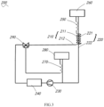
Figure 3 is a schematic diagram of the refrigeration system of the refrigerator shown inFigure 1 ; -
Figure 4 is an exploded view of a refrigerator according to another embodiment of the present application; -
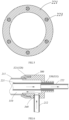
Figure 5 is a cross-sectional view of the flexible return pipe according to yet another embodiment of the present application; -
Figure 6 is a partial schematic view according to yet another embodiment of the present application; -
Figure 7 is a cross-sectional schematic view of the flexible intake pipe and flexible return pipe shown inFigure 6 . - In order to enable those skilled in the art to better understand the technical solutions in the present application, the technical solutions in the embodiments of the present application will be clearly and completely described below with reference to the drawings in the embodiments of the present application. Obviously, the described embodiments are only a part of the embodiments of the present application, not all embodiments. Based on the embodiments in the present application, all other embodiments obtained by those skilled in the art without creative efforts should fall within the protection scope of the present application.
- Referring to
Figures 1 and2 , arefrigerator 100 according to an embodiment of the present application is provided,refrigerator 100 comprises acabinet 110 and adoor 120 for opening and closing thecabinet 110. Thedoor 120 can be pivotally connected to thecabinet 110 via ahinge 130, thehinge 130 has a hinge plate fixedly connected to thecabinet 110 and ahinge axis 132 pivotally connected to thedoor 120. Thedoor 110 is provided with a door axis, and thehinge axis 132 is connected to the door axis, so that the door can rotate relative to the cabinet. Both thecabinet 110 and thedoor 120 can be provided with thermal insulation layers to prevent the loss of cold air inside therefrigerator 100. Specifically, thecabinet 110 can comprise an outer shell and an inner liner, with a thermal insulation layer provided between the outer shell and the inner liner. Thedoor 120 can comprise a door shell and a door liner, with a thermal insulation layer provided between the door shell and the door liner. The thermal insulation layer can be made of foam material. The inner liner of thecabinet 110 forms a storage compartment, the storage compartment can comprise a refrigeration compartment and a freezing compartment. - The
door 120 of the refrigeration compartment can be provided with an ice-making compartment and an ice-making door for opening and closing the ice-making compartment. The ice-making door is filled with thermal insulation material to isolate the ice-making compartment from the refrigeration compartment. The ice-making compartment can be equipped with an ice-making device and an ice storage device. - The
refrigerator 100 also comprises arefrigeration system 200. Referring toFigures 2 and3 , therefrigeration system 200 can comprise acompressor 230, acondenser 240, a doorcapillary tube 250, and adoor evaporator 260 connected in sequence. Thecompressor 230 and thecondenser 240 can be installed on a cabinet side, such as in a compressor compartment provided on the cabinet side, which can be located at the bottom of thecabinet 110. Thecompressor 230 and thecondenser 240 can be installed inside the compressor compartment. - In this embodiment, the
door evaporator 260 can be installed inside thedoor 120. Specifically, thedoor evaporator 260 can be installed inside the ice-making compartment to supply cold air to the ice-making compartment. The cabinet side is also provided with acabinet evaporator 280 and a cabinetcapillary tube 270. Thecabinet evaporator 280 can supply cold air to the refrigeration compartment and the freezing compartment. Thecabinet evaporator 280 and thedoor evaporator 260 can share thecompressor 230 and thecondenser 240. Specifically, thecompressor 230 is connected to thecondenser 240 via a refrigerant pipe. Thecondenser 240 is connected to a one-in-two-outsolenoid valve 290, which supplies refrigerant to both thedoor evaporator 260 and thecabinet evaporator 280. The refrigerant flowing through thedoor evaporator 260 and thecabinet evaporator 280 returns to thecompressor 230 in the compressor compartment. - In this embodiment, the
condenser 240 is connected to thedoor evaporator 260 via anintake pipe 210, and thedoor evaporator 260 is connected to thecompressor 230 via areturn pipe 220. Theintake pipe 210 can pass through the thermal insulation layer of thecabinet 110 from the compressor compartment and then enter the thermal insulation layer of thedoor 120 to connect with thedoor evaporator 260. One end of thereturn pipe 220 is connected to thedoor evaporator 260 and passes through the thermal insulation layer of thedoor 120, then enters the thermal insulation layer of thecabinet 110, and finally enters the compressor compartment to connect with thecompressor 230. - In one embodiment of the present application, a
pipe port 111 is provided on thecabinet 110. Thepipe port 111 can be provided at the top of thecabinet 110. Thereturn pipe 220 enters the door shaft on the door side from the thermal insulation layer of thedoor 120, passes out through thehinge axis 132 on the door side, and then enters the thermal insulation layer of thecabinet 110 from thepipe port 111 on thecabinet 110. Therefrigerator 100 also comprises a thermally insulatedhinge cover plate 131. Thehinge cover plate 131 at least covers the exposedreturn pipe 220 between thehinge axis 132 and thepipe port 111. Thehinge cover plate 131 can be directly installed on thecabinet 110 using screws or other fasteners. Since thehinge cover plate 131 is thermally insulated and covers the part of thereturn pipe 220 exposed outside thecabinet 110 and thedoor 120, thereturn pipe 220 does not directly contact the outside, and therefore, condensation will not occur on the exterior of the low-temperature return pipe 220. Thehinge cover plate 131 covers thereturn pipe 220, making the overall appearance more aesthetically pleasing and the structure compact and easy to install and manufacture. - In this embodiment, the
hinge cover plate 131 comprises a hinge shell and thermal insulation foam fixed to the inside of the hinge shell. The thermal insulation foam can be snap-fitted and fixed inside the hinge shell. In the manufacturing process, after the installation of therefrigeration system 200, thehinge cover plate 131 can be directly installed, making the installation process simple. - A
pipeline guide box 140 can also be provided on thecabinet 110. Specifically, thepipeline guide box 140 can be provided at the top of thecabinet 110 near the edge of an opening side. Thepipeline guide box 140 comprises apipeline guide groove 141 provided close to thehinge 130 side. Theintake pipe 210 and thereturn pipe 220 can pass through thepipeline guide groove 141 and then enter thepipe port 111. Thehinge cover plate 131 covers thepipeline guide groove 140 and abuts against the sidewall of thepipeline guide groove 141. Thepipeline guide groove 141 can guide and position the pipelines while also limiting the position of thehinge cover plate 131. - Further, a guide groove for accommodating the
return pipe 220 can be provided on thehinge cover plate 131. Specifically, the guide groove can be provided on the thermal insulation foam. When thehinge cover plate 131 is installed on thedoor 120, thereturn pipe 220 passes out from thehinge axis 132 on the door side, passes through the guide groove of thehinge cover plate 131, and then enters the thermal insulation layer of thecabinet 110 from thepipe port 111 on thecabinet 110. The guide groove can position thereturn pipe 220, making the covering of thereturn pipe 220 tighter and enhancing the anti-condensation effect. - Further, in one embodiment of the present application, the door
capillary tube 250 can be set inside thedoor 120. Specifically, the doorcapillary tube 250 can be set inside the thermal insulation layer of thedoor 120. Thecondenser 240 is connected to the doorcapillary tube 250 via a first intake pipe, and the doorcapillary tube 250 is connected to thedoor evaporator 260 via a second intake pipe. The first intake pipe exits the thermal insulation layer of thecabinet 110 and enters the door shaft of thedoor 120 from thehinge axis 132 on the door side, and then connects to the doorcapillary tube 250 inside the thermal insulation layer of thedoor 120. The doorcapillary tube 250 can also partially extend into the door shaft of thedoor 120. The first intake pipe connects to the doorcapillary tube 250 inside the door shaft after passing through thehinge axis 132 on thedoor 120 side. The doorcapillary tube 250 and thereturn pipe 220 form at least a part of the tube bundle, ensuring heat exchange effectiveness. - The portion of the first intake pipe disposed between the
door 120 and thecabinet 110 is exposed outside of thedoor 120 and thecabinet 110, but since the doorcapillary tube 250 is located inside thedoor 120, the refrigerant flowing through the first intake pipe is at room temperature, so the first intake pipe does not have a condensation problem. - Further, the
intake pipe 210 can pass out from thepipe port 111 on thecabinet 110 and enter the door shaft of thedoor 120 from thehinge axis 132 on the door side, then enter the thermal insulation layer of thedoor 120. The thermally insulatedhinge cover plate 131 can cover theintake pipe 210 between thehinge axis 132 and thepipe port 111. Thus, even if the doorcapillary tube 250 is located on the cabinet side, theintake pipe 210 will not have a condensation problem. - The
return pipe 220 can comprise aflexible return pipe 221 and areturn copper pipe 222 connected to theflexible return pipe 221. Theintake pipe 210 can comprise aflexible intake pipe 211 and anintake copper pipe 212. Theflexible intake pipe 211 and theflexible return pipe 221 at least extend from thehinge axis 132 on the door side to the cabinet side, so they do not hinder the opening and closing of thedoor 120, and the flexible pipes are flexible, not easily damaged by the rotation of thedoor 120. Theintake copper pipe 212 and thereturn copper pipe 222 ensure good heat exchange. - Specifically, the
intake pipe 210 can comprise an intake copper pipe on the door side and anintake copper pipe 212 on the cabinet side. The intake copper pipe on the door side can be embedded in the thermal insulation layer of thedoor 120. Both ends of theflexible intake pipe 211 can be connected to the intake copper pipe on the door side and theintake copper pipe 212 on the cabinet side. Theflexible intake pipe 211 can enter the door shaft of thedoor 120 from the hinge axis on the door side and connect to the intake copper pipe inside the door shaft, the intake copper pipe set on the door side, or theflexible intake pipe 211 can directly extend into the thermal insulation layer of thedoor 120 and connect to the intake copper pipe inside the thermal insulation layer, the intake copper pipe is set on the door side. Theintake copper pipe 212 on the cabinet side can connect to thecondenser 240 inside the compressor compartment, and the intake copper pipe on the door side can connect to the doorcapillary tube 250. - The
return copper pipe 222 also comprises areturn copper pipe 222 on the cabinet side and a return copper pipe on the door side. Thereturn copper pipe 222 on the cabinet side connects to the refrigerant inlet of thecompressor 230, and the return copper pipe on the door side connects to the refrigerant outlet of thedoor evaporator 260. Both ends of theflexible return pipe 221 can be connected to theintake copper pipe 212 on the cabinet side and the return copper pipe on the door side. Theflexible return pipe 221 can enter the door shaft of thedoor 120 from the hinge axis on the door side, and inside the door shaft theflexible return pipe 221 connect to the return copper pipe on the door side. Theflexible return pipe 221 can also enter the thermal insulation layer of thedoor 120 after entering the door shaft and connect to the return copper pipe on the door side inside the thermal insulation layer. - Further, in one embodiment of the present application, the axis of the
pipe port 111 on thecabinet 110 is parallel to the axis of thehinge axis 132. Thehinge cover plate 131 covers both thehinge axis 132 and thepipe port 111. - In this embodiment, both the
return pipe 220 and theintake pipe 210 can pass out from thehinge axis 132 of thedoor 120 and then enter the interior of thecabinet 110 from thepipe port 111. The axis of thepipe port 111 is parallel to thehinge axis 132, which can reduce damage to thereturn pipe 220 and theintake pipe 210 during the rotation of thedoor 120. - The
flexible intake pipe 211 and theflexible return pipe 221 both pass out from thehinge axis 132 on the door side and passes through the thermal insulation layer of thecabinet 110 from thepipe port 111, and then enters into the compressor compartment to connect with theintake copper pipe 212 and thereturn copper pipe 222 inside the compressor compartment, respectively. Therefrigerator 100 can also be equipped with a water supply device, which can supply water to the ice-making device inside the ice-making compartment. The water pipe of the water supply device can also pass out from the thermal insulation layer of thedoor 120 through thehinge axis 132 on t the door side and enter the thermal insulation layer of thecabinet 110 through thepipe port 111. The water pipe,flexible return pipe 221, andflexible intake pipe 211 can form a bundle, which is convenient for installation and manufacturing. The interface between theflexible return pipe 221 and thereturn copper pipe 222 on the cabinet side, and the interface between theflexible intake pipe 211 and theintake copper pipe 212 are both located inside the compressor compartment, eliminating the need for additional connection space on thecabinet 110. Thehinge cover plate 131 directly covers the area between thehinge axis 132 on the door side and thepipe port 111, achieving anti-condensation for thereturn pipe 220 with a compact overall structure. - Referring to
Figure 4 , in another embodiment of the present application, thecabinet 110 is provided with apipeline accommodation groove 112 and athermal insulation cover 113 that closes thepipeline accommodation groove 112. Thepipe port 111 can be set inside thepipeline accommodation groove 112. Both theintake copper pipe 212 and thereturn copper pipe 222 pass through the thermal insulation layer of thecabinet 110 from the compressor compartment and exit from thepipe port 111 on thecabinet 110, and then connect to theflexible intake pipe 211 and theflexible return pipe 221, respectively. The interface between theflexible intake pipe 211 and theintake copper pipe 212, and the interface between theflexible return pipe 221 and thereturn copper pipe 222 are both located inside thepipeline accommodation groove 112. - In this embodiment, the top of the
cabinet 110 is recessed to form thepipeline accommodation groove 112, and thepipe port 111 is set on the sidewall of thepipeline accommodation groove 112. Thethermal insulation cover 113 and thehinge cover plate 131 can be set separately. Theflexible return pipe 221 passes into thehinge cover plate 131 from thehinge axis 132 of thedoor 120, then exits from thehinge cover plate 131 and enters thethermal insulation cover 113. Thethermal insulation cover 113 and thehinge cover plate 131 together cover thereturn pipe 220 between thehinge axis 132 on the door side and thepipe port 111. The thermal insulation cover1 13 can be a part of thehinge cover plate 131, or thethermal insulation cover 113 can be integrally formed with thehinge cover plate 131, making installation and manufacturing more convenient. - Thus, since the price of flexible pipes is higher than that of copper pipes, this configuration can reduce the length of the flexible pipes, lowering production and manufacturing costs, and making installation and manufacturing more convenient.
- Referring to
Figure 5 , in another embodiment of the present application, aheating wire 223 is embedded in the wall of theflexible return pipe 221 at least between thehinge axis 132 on the door side and thepipe port 111 of thecabinet 110. Theflexible return pipe 221 extends from thehinge axis 132 on the door side to the cabinet side to avoid hindering the opening and closing of thedoor 120 and to extend the lifespan of thereturn pipe 220. - The
heating wire 223 can exit from the end surface of one end of theflexible return pipe 221 and connect to a wire harness, the wire harness can enter the interior of thecabinet 110 or thedoor 120 of therefrigerator 100 and connect to the control board of therefrigerator 100. The control board can control the on/off state of theheating wire 223, such as turning on theheating wire 223 only when thecompressor 230 is operating to supply refrigerant to thedoor evaporator 260. - The portion of the
flexible return pipe 221 between thehinge axis 132 on the door side and thepipe port 111 of thecabinet 110 is exposed to the external environment. Since the refrigerant flowing through theflexible return pipe 221 is at a low temperature, the exterior of theflexible return pipe 221 is prone to condensation. By embedding theheating wire 223 in the wall of theflexible return pipe 221 in this portion, and integrating theheating wire 223 with theflexible return pipe 221, the condensation problem of theflexible return pipe 221 can be solved. Additionally, theheating wire 223 is embedded in the wall of theflexible return pipe 221, occupying a small overall space and being convenient for installation. The closure of theflexible return pipe 221 can protect theheating wire 223, and the high toughness of theheating wire 223 can also enhance the toughness of theflexible return pipe 221, increasing its lifespan. - Furthermore, in one embodiment of the present application, a
heating wire 223 of the same length as theflexible return pipe 221 is embedded in the wall of theflexible return pipe 221, meaning the entire wall of theflexible return pipe 221 has an embeddedheating wire 223, making manufacturing more convenient and improving the anti-condensation effect. - The
heating wire 223 comprises multiple resistance wires set at intervals along the circumference of thereturn pipe 220. The resistance wires have good toughness, are not easily broken, and can better enhance the toughness of theflexible return pipe 221. The multiple resistance wires are set at intervals along the circumference of thereturn pipe 220, and the distance between any two adjacent resistance wires can be equal, which can make the heating of thereturn pipe 220 more uniform, improving the anti-condensation effect. - Referring to
Figures 6 and7 , another embodiment of the present application provides arefrigerator 100. In this embodiment, thecompressor 230 and thecondenser 240 of therefrigeration system 200 are installed inside the compressor compartment on the cabinet side, and both the doorcapillary tube 250 and thedoor evaporator 260 are installed inside thedoor 120. In this way, during the refrigeration process, the refrigerant flowing through theintake pipe 210 between thecondenser 240 and the doorcapillary tube 250 is at room temperature, so theintake pipe 210 will not have a condensation problem. - In this embodiment, both the
intake pipe 210 and thereturn pipe 220 pass out from thehinge axis 132 on the door side and enter the thermal insulation layer of thecabinet 110 through thepipe port 111. Theintake pipe 210 comprises at least aflexible intake pipe 211 extending from thehinge axis 132 on the door side to the cabinet side. Thereturn pipe 220 comprises at least aflexible return pipe 221 extending from thehinge axis 132 on the door side to the cabinet side, and at least theflexible return pipe 221 between thehinge axis 132 on the door side and thepipe port 111 is placed inside theflexible intake pipe 211. - The refrigerant inside the
flexible return pipe 221 between thehinge axis 132 on the door side and thepipe port 111 is at a low temperature. If theflexible return pipe 221 is directly exposed to the external environment, it may produce condensation. Placing theflexible return pipe 221 inside theflexible intake pipe 211 can avoid direct exposure of theflexible return pipe 221 to the external environment, and the exterior of theflexible return pipe 221 is simultaneously wrapped by theflexible intake pipe 211 and the room-temperature refrigerant, so theflexible return pipe 221 will not have condensation. The overall structure is compact, does not occupy additional space, and the nesting of theflexible intake pipe 211 and theflexible return pipe 221 does not affect the opening and closing of thedoor 120 or the lifespan of the pipelines. - Furthermore, the
return pipe 220 comprises areturn copper pipe 222 connected to theflexible return pipe 221, and theintake pipe 210 comprises anintake copper pipe 212 connected to theflexible intake pipe 211. Theflexible return pipe 221 is entirely placed inside theflexible intake pipe 211, which facilitates connection and manufacturing and can enhance the anti-condensation effect. - The
flexible return pipe 221 and theflexible intake pipe 211 can be integrally formed, and supportribs 224 can be set between theflexible return pipe 221 and theflexible intake pipe 211, so that thereturn pipe 220 is fixed relative to theintake pipe 210. The pipelines between thereturn pipe 220 and theintake pipe 210 are relatively fixed, and the refrigerant from thecompressor 230 can smoothly flow through the channel between theintake pipe 210 and thereturn pipe 220 into the doorcapillary tube 250, without affecting the refrigeration effect. At the same time, thesupport ribs 224 can also enhance the stability of the overall structure and the strength of the pipelines, facilitating installation and manufacturing. - Furthermore, in one embodiment of the present application, the
refrigerator 100 also comprises adiversion connector 300, which connects theflexible intake pipe 211,intake copper pipe 212,flexible return pipe 221, and returncopper pipe 222. Thediversion connector 300 can comprise adiversion connector 300 on the cabinet side and adiversion connector 300 on the door side. During the refrigeration process, the refrigerant from thecompressor 230 enters theflexible intake pipe 211 through theintake copper pipe 212 via thediversion connector 300, then enters the intake copper pipe on the door side through thediversion connector 300, flows through the doorcapillary tube 250 and thedoor evaporator 260, enters the return copper pipe on the door side, passes through thediversion connector 300 on the door side, enters theflexible return pipe 221, passes through thediversion connector 300 on the cabinet side, enters thereturn copper pipe 222 on the cabinet side, and returns to thecompressor 230. - The
diversion connector 300 comprises afluid chamber 310 and a flexible intakepipe connection part 320 penetrating thefluid chamber 310 and a returnpipe connection part 330. The end of theflexible intake pipe 211 is connected to the flexible intakepipe connection part 320, and theflexible return pipe 221 passes through thefluid chamber 310 from the flexible intake pipe connection part side and connects to the returnpipe connection part 330. A space is formed between theflexible return pipe 221 and the sidewall of thefluid chamber 310, the space communicates with theflexible intake pipe 211. Thediversion connector 300 also comprises an intake copperpipe connection part 340 penetrating thefluid chamber 310, theintake copper pipe 212 is connected to the intake copperpipe connection part 340. - In this embodiment, the
fluid chamber 310 is cylindrical, and the inner diameter of thefluid chamber 310 is larger than the outer diameter of theflexible return pipe 221. The two ends of thefluid chamber 310 are open and provided with the flexible intakepipe connection part 320 connecting to theflexible intake pipe 211 and the returnpipe connection part 330 connecting to thereturn pipe 220 respectively. An opening is formed on the sidewall of thefluid chamber 310 for connecting theintake copper pipe 212 to the intake copperpipe connection part 340. Thereturn copper pipe 222 can connect directly to theflexible return pipe 221 or through the returnpipe connection part 330.Figure 6 shows a schematic diagram of the connection of the diversion connector on the cabinet side, where the arrows represent the direction of the refrigerant flow. During the refrigeration process, the refrigerant flows from theintake copper pipe 212 to space between theflexible return pipe 221 and thefluid chamber 310, then flow into between theflexible intake pipe 211 and theflexible return pipe 221 directly. The refrigerant inflexible return pipe 221 can flow directly intoreturn copper pipe 222 connected to it. - The return
pipe connection part 330 can include a connectingpipe sleeve 331 placed on one side offluid chamber 310. Theflexible return pipe 221 passes through thefluid chamber 310 and is placed inside the connectingpipe sleeve 331. Theflexible return pipe 221 and the connectingpipe sleeve 331 have an interference fit, and thereturn copper pipe 222 can be placed inside theflexible return pipe 221 with an interference fit as well. Specifically, both thereturn copper pipe 222 and theflexible return pipe 221 can be placed inside the connectingpipe sleeve 331, thereturn copper pipe 222 can be placed inside theflexible return pipe 221. The arrangement from outside to inside is the connectingpipe sleeve 331, theflexible return pipe 221, and thereturn copper pipe 222, and they are interference fit with each other through mechanical compression. - The flexible intake
pipe connection part 320 includes a threaded connectingsleeve 321, one end of the threaded connectingsleeve 321 mating with theflexible intake pipe 211, and the other end threaded to the outer wall of thefluid chamber 310. In this embodiment, the threaded connectingsleeve 321 can mate with theflexible intake pipe 211 directly or through threaded connection. The end of theflexible intake pipe 211 and the threaded connectingsleeve 321 are both mounted on the outer wall of thefluid chamber 310, the outer wall of thefluid chamber 310 is provided with external threads, the threaded connectingsleeve 321 is provided with internal threads. During installation, theflexible intake pipe 211 can be connected to thediversion connector 300 by the threaded connectingsleeve 321. The intake copperpipe connection part 340 can be an opening on a side wall of thefluid cavity 310, and theintake copper pipe 212 can be directly bonded to the intake copperpipe connection part 340 using metal adhesive. Furthermore, in one embodiment of the present application, thediversion connector 300 on the cabinet side is located in the compressor compartment on the cabinet side. In this embodiment, both theflexible intake pipe 211 and theflexible return pipe 221 pass out from thehinge axis 132 on the door side and through thepipe port 111 on thecabinet 110, then through the thermal insulation layer of thecabinet 110 and into the compressor compartment on the cabinet side. Inside the compressor compartment, theflexible intake pipe 211 and theflexible return pipe 221 connect to theintake copper pipe 212 and thereturn copper pipe 222 through thediversion connector 300. - In this embodiment, only one refrigerant pipe needs to be installed through the interior of the
cabinet 110 during the manufacturing process, which simplifies the manufacturing process. Thereturn pipe 220 is placed inside theintake pipe 210 and directly enters the foam layer through thepipe port 111 on thecabinet 110. There are no parts of thereturn pipe 220 exposed on the exterior, so there is no risk of condensation, and no additional structures are required. - In another embodiment of the present application, the
cabinet 110 is provided with apipeline accommodation groove 112 and athermal insulation cover 113 that seals thepipeline accommodation groove 112. Thediversion connector 300 is located inside thepipeline accommodation groove 112. Both theintake copper pipe 212 and thereturn copper pipe 222 pass through the thermal insulation layer of thecabinet 110 from the compressor compartment, enter thepipeline accommodation groove 112 through thepipe port 111, and connect to thediversion connector 300. Both theflexible return pipe 221 and theflexible intake pipe 211 extend from thehinge axis 132 on the door side to the cabinet side and connect to thediversion connector 300. - In this embodiment, the length of the
flexible return pipe 221 and theflexible intake pipe 211 is reduced, which can lower costs. However, condensation may occur at thediversion connector 300. Therefore, by setting thepipeline accommodation groove 112 on thecabinet 110 and sealing it with thethermal insulation cover 113, and placing thediversion connector 300 inside thepipeline accommodation groove 112, condensation at thediversion connector 300 can be avoided. - It should be understood that although the present application has been described in accordance with the embodiments, not every embodiment contains only one independent technical solution. The description in the specification is merely for clarity, and those skilled in the art should consider the specification as a whole. The technical solutions in the various embodiments may also be appropriately combined to form other embodiments that can be understood by those skilled in the art.
- The series of detailed explanations listed above are merely specific descriptions of feasible embodiments of the present application and are not intended to limit the scope of protection of the present application. Any equivalent embodiments or changes made without departing from the spirit of the present application should be comprised within the scope of protection of the present application.
Claims (10)
- A refrigerator comprising:a cabinet;a door, wherein the door is pivotally connected to the cabinet via a hinge;a refrigeration system, which comprises a compressor, a condenser, and a door evaporator connected in sequence, wherein the compressor and the condenser are located on a cabinet side, and the door evaporator is located on a door side; the condenser is connected to the door evaporator via an intake pipe, and the door evaporator is connected to the compressor via a return pipe;characterized in that, the cabinet is provided with a pipe port, and the return pipe passes through the pipe port into a thermal insulation layer of the cabinet after passing out of a hinge axis on the door side;the return pipe comprises a flexible return pipe at least extending from the hinge axis on the door side to the cabinet side, and at least a wall of the flexible return pipe between the hinge axis on the door side and the pipe port is embedded with a heating wire.
- The refrigerator according to claim 1, characterized in that the heating wire comprises multiple resistance wires arranged at intervals along a circumference of the return pipe.
- The refrigerator according to claim 1, characterized in that a wall of the flexible return pipe is embedded with a heating wire that is equal in length to the flexible return pipe.
- The refrigerator according to claim 1, characterized in that the refrigeration system further comprises a door capillary tube, which is located on the door side and positioned between the condenser and the door evaporator.
- The refrigerator according to claim 1, characterized in that the cabinet comprises an outer shell and an inner liner, the thermal insulation layer is located between the outer shell and the inner liner, and the inner liner forms a storage compartment.
- The refrigerator according to claim 1, characterized in that the cabinet side is provided with a compressor compartment for installing the compressor, and the return pipe comprises a flexible return pipe and a return copper pipe, the flexible return pipe passes out of the hinge axis on the door side, passes through the thermal insulation layer of the cabinet from the pipe port, and enters into the compressor compartment to connect with the return copper pipe.
- The refrigerator according to claim 6, characterized in that the intake pipe comprises a flexible intake pipe and an intake copper pipe, the flexible intake pipe passes out of the hinge axis on the door side, passes through the thermal insulation layer of the cabinet from the pipe port, and enters into the compressor compartment to connect with the intake copper pipe.
- The refrigerator according to claim 1, characterized in that the cabinet side is provided with a compressor compartment for installing the compressor , and the return pipe comprises a flexible return pipe and a return copper pipe , the return copper pipe passes through the thermal insulation layer of the cabinet from the compressor compartment and passes out from the pipe port, the flexible return pipe extends from the hinge axis to the cabinet side and connects with the return copper pipe.
- The refrigerator according to claim 8, characterized in that the intake pipe comprises a flexible intake pipe and an intake copper pipe, the intake copper pipe passes through the thermal insulation layer of the cabinet from the compressor compartment and passes out from the pipe port), the intake copper pipe extends from the hinge axis on the door side to the cabinet side and connects with the intake copper pipe, the cabinet is provided with a pipeline accommodation groove and a thermal insulation cover that closes the pipeline accommodation groove , the pipe port is located in the pipeline accommodation groove , and an interface between the flexible intake pipe and the intake copper pipe and an interface between the flexible return pipe and the return copper pipe are located in the pipeline accommodation groove.
- The refrigerator according to claim 1, characterized in that a storage compartment formed inside the cabinet comprises a refrigeration compartment and a freezing compartment, a refrigeration door for opening and closing the refrigeration compartment is provided with an ice-making compartment, and the door evaporator is located inside the ice-making compartment.
Applications Claiming Priority (2)
| Application Number | Priority Date | Filing Date | Title |
|---|---|---|---|
| CN202111355812.4A CN116136348A (en) | 2021-11-16 | 2021-11-16 | refrigerator |
| PCT/CN2022/130927 WO2023088152A1 (en) | 2021-11-16 | 2022-11-09 | Refrigerator |
Publications (2)
| Publication Number | Publication Date |
|---|---|
| EP4435356A1 true EP4435356A1 (en) | 2024-09-25 |
| EP4435356A4 EP4435356A4 (en) | 2025-02-26 |
Family
ID=86332610
Family Applications (1)
| Application Number | Title | Priority Date | Filing Date |
|---|---|---|---|
| EP22894689.3A Pending EP4435356A4 (en) | 2021-11-16 | 2022-11-09 | Refrigerator |
Country Status (3)
| Country | Link |
|---|---|
| EP (1) | EP4435356A4 (en) |
| CN (1) | CN116136348A (en) |
| WO (1) | WO2023088152A1 (en) |
Family Cites Families (10)
| Publication number | Priority date | Publication date | Assignee | Title |
|---|---|---|---|---|
| KR20080015341A (en) * | 2006-08-14 | 2008-02-19 | 삼성전자주식회사 | Refrigerator |
| US8136367B2 (en) * | 2008-12-11 | 2012-03-20 | General Electric Company | Hinge assembly for a refrigerator |
| CN204403596U (en) * | 2014-10-29 | 2015-06-17 | 无锡金顶石油管材配件制造有限公司 | Petroleum pipeline |
| CN104729134A (en) * | 2015-04-07 | 2015-06-24 | 合肥华凌股份有限公司 | Refrigerating system for refrigerator and refrigerator with same |
| KR101883436B1 (en) * | 2016-04-11 | 2018-07-31 | 주식회사 대우전자 | Refrigerator |
| CN207778907U (en) * | 2017-12-22 | 2018-08-28 | 青岛海尔股份有限公司 | Refrigerator |
| CN113048693A (en) * | 2019-12-26 | 2021-06-29 | 青岛海尔电冰箱有限公司 | Refrigerator with a door |
| CN212431447U (en) * | 2020-05-07 | 2021-01-29 | 青岛海尔智能技术研发有限公司 | Refrigerator with a door |
| CN113623917A (en) * | 2020-05-07 | 2021-11-09 | 青岛海尔智能技术研发有限公司 | Refrigerator with a door |
| CN113482473A (en) * | 2021-07-21 | 2021-10-08 | 青岛海尔电冰箱有限公司 | Hinge assembly and refrigerator |
-
2021
- 2021-11-16 CN CN202111355812.4A patent/CN116136348A/en active Pending
-
2022
- 2022-11-09 WO PCT/CN2022/130927 patent/WO2023088152A1/en not_active Ceased
- 2022-11-09 EP EP22894689.3A patent/EP4435356A4/en active Pending
Also Published As
| Publication number | Publication date |
|---|---|
| CN116136348A (en) | 2023-05-19 |
| WO2023088152A8 (en) | 2024-04-18 |
| EP4435356A4 (en) | 2025-02-26 |
| WO2023088152A1 (en) | 2023-05-25 |
Similar Documents
| Publication | Publication Date | Title |
|---|---|---|
| US10584916B2 (en) | Water-feed assembly of ice maker in refrigerator and refrigerator | |
| US10168094B2 (en) | Refrigerator | |
| US5743109A (en) | Energy efficient domestic refrigeration system | |
| US20090058244A1 (en) | Refrigerator | |
| US20200393187A1 (en) | Ice maker-integrated refrigerator | |
| CN103673468A (en) | Freezer | |
| CN212431447U (en) | Refrigerator with a door | |
| EP4435356A1 (en) | Refrigerator | |
| EP4435357A1 (en) | Refrigerator | |
| AU2022389259B2 (en) | Refrigerator | |
| US10156394B2 (en) | Air flow and drainage system for ice maker | |
| CN108224875A (en) | A kind of horizontal frostless two-temperature freezer | |
| CN201340154Y (en) | Refrigerator | |
| US11828523B2 (en) | Connector for increasing heat transfer between a refrigerant loop and a refrigerator appliance casing | |
| CN111879051B (en) | Air duct components and refrigerator | |
| CN219199628U (en) | Refrigerating appliance | |
| CN208332806U (en) | A kind of horizontal frostless two-temperature freezer | |
| CN214039122U (en) | Refrigerating and freezing device | |
| CN108800700A (en) | Refrigerating appliance | |
| CN221924116U (en) | Partition assembly, air duct assembly, box assembly and refrigeration equipment | |
| KR100909466B1 (en) | Water pipe installation structure of the refrigerator | |
| CN219346912U (en) | Refrigerator with a refrigerator body | |
| CN222718447U (en) | Refrigeration equipment door body and refrigeration equipment | |
| CN214039123U (en) | Refrigerating and freezing device | |
| CN120176361A (en) | Refrigerating apparatus |
Legal Events
| Date | Code | Title | Description |
|---|---|---|---|
| STAA | Information on the status of an ep patent application or granted ep patent |
Free format text: STATUS: THE INTERNATIONAL PUBLICATION HAS BEEN MADE |
|
| PUAI | Public reference made under article 153(3) epc to a published international application that has entered the european phase |
Free format text: ORIGINAL CODE: 0009012 |
|
| STAA | Information on the status of an ep patent application or granted ep patent |
Free format text: STATUS: REQUEST FOR EXAMINATION WAS MADE |
|
| 17P | Request for examination filed |
Effective date: 20240327 |
|
| AK | Designated contracting states |
Kind code of ref document: A1 Designated state(s): AL AT BE BG CH CY CZ DE DK EE ES FI FR GB GR HR HU IE IS IT LI LT LU LV MC ME MK MT NL NO PL PT RO RS SE SI SK SM TR |
|
| DAV | Request for validation of the european patent (deleted) | ||
| DAX | Request for extension of the european patent (deleted) | ||
| A4 | Supplementary search report drawn up and despatched |
Effective date: 20250128 |
|
| RIC1 | Information provided on ipc code assigned before grant |
Ipc: F25D 23/06 20060101ALI20250122BHEP Ipc: F25D 23/00 20060101ALI20250122BHEP Ipc: F25D 21/04 20060101ALI20250122BHEP Ipc: F25C 5/20 20180101ALI20250122BHEP Ipc: F25D 23/02 20060101ALI20250122BHEP Ipc: F25D 11/02 20060101AFI20250122BHEP |