EP4435354A1 - Refrigerator - Google Patents
Refrigerator Download PDFInfo
- Publication number
- EP4435354A1 EP4435354A1 EP22894687.7A EP22894687A EP4435354A1 EP 4435354 A1 EP4435354 A1 EP 4435354A1 EP 22894687 A EP22894687 A EP 22894687A EP 4435354 A1 EP4435354 A1 EP 4435354A1
- Authority
- EP
- European Patent Office
- Prior art keywords
- ice
- pipe
- making compartment
- ice tray
- bracket
- Prior art date
- Legal status (The legal status is an assumption and is not a legal conclusion. Google has not performed a legal analysis and makes no representation as to the accuracy of the status listed.)
- Pending
Links
- 239000003507 refrigerant Substances 0.000 claims abstract description 76
- 238000009434 installation Methods 0.000 claims description 88
- XLYOFNOQVPJJNP-UHFFFAOYSA-N water Substances O XLYOFNOQVPJJNP-UHFFFAOYSA-N 0.000 claims description 54
- 238000010438 heat treatment Methods 0.000 claims description 48
- 238000001816 cooling Methods 0.000 claims description 42
- 238000010257 thawing Methods 0.000 claims description 42
- 238000005057 refrigeration Methods 0.000 claims description 31
- 238000007710 freezing Methods 0.000 claims description 10
- 230000008014 freezing Effects 0.000 claims description 10
- 238000003860 storage Methods 0.000 claims description 10
- 239000006260 foam Substances 0.000 claims description 5
- 239000011810 insulating material Substances 0.000 claims description 3
- 238000005187 foaming Methods 0.000 description 15
- 239000000463 material Substances 0.000 description 11
- 238000000034 method Methods 0.000 description 8
- 238000010586 diagram Methods 0.000 description 7
- 230000005494 condensation Effects 0.000 description 6
- 238000009833 condensation Methods 0.000 description 6
- 238000004519 manufacturing process Methods 0.000 description 5
- XAGFODPZIPBFFR-UHFFFAOYSA-N aluminium Chemical compound [Al] XAGFODPZIPBFFR-UHFFFAOYSA-N 0.000 description 3
- 229910052782 aluminium Inorganic materials 0.000 description 3
- 230000002708 enhancing effect Effects 0.000 description 3
- 230000001965 increasing effect Effects 0.000 description 2
- 238000002844 melting Methods 0.000 description 2
- 230000008018 melting Effects 0.000 description 2
- 230000003213 activating effect Effects 0.000 description 1
- 238000005452 bending Methods 0.000 description 1
- 238000009826 distribution Methods 0.000 description 1
- 230000001737 promoting effect Effects 0.000 description 1
- 230000005855 radiation Effects 0.000 description 1
- 239000008400 supply water Substances 0.000 description 1
Images



Classifications
-
- F—MECHANICAL ENGINEERING; LIGHTING; HEATING; WEAPONS; BLASTING
- F25—REFRIGERATION OR COOLING; COMBINED HEATING AND REFRIGERATION SYSTEMS; HEAT PUMP SYSTEMS; MANUFACTURE OR STORAGE OF ICE; LIQUEFACTION SOLIDIFICATION OF GASES
- F25C—PRODUCING, WORKING OR HANDLING ICE
- F25C5/00—Working or handling ice
- F25C5/02—Apparatus for disintegrating, removing or harvesting ice
- F25C5/04—Apparatus for disintegrating, removing or harvesting ice without the use of saws
- F25C5/08—Apparatus for disintegrating, removing or harvesting ice without the use of saws by heating bodies in contact with the ice
-
- F—MECHANICAL ENGINEERING; LIGHTING; HEATING; WEAPONS; BLASTING
- F25—REFRIGERATION OR COOLING; COMBINED HEATING AND REFRIGERATION SYSTEMS; HEAT PUMP SYSTEMS; MANUFACTURE OR STORAGE OF ICE; LIQUEFACTION SOLIDIFICATION OF GASES
- F25C—PRODUCING, WORKING OR HANDLING ICE
- F25C1/00—Producing ice
- F25C1/04—Producing ice by using stationary moulds
-
- F—MECHANICAL ENGINEERING; LIGHTING; HEATING; WEAPONS; BLASTING
- F25—REFRIGERATION OR COOLING; COMBINED HEATING AND REFRIGERATION SYSTEMS; HEAT PUMP SYSTEMS; MANUFACTURE OR STORAGE OF ICE; LIQUEFACTION SOLIDIFICATION OF GASES
- F25C—PRODUCING, WORKING OR HANDLING ICE
- F25C1/00—Producing ice
- F25C1/22—Construction of moulds; Filling devices for moulds
- F25C1/24—Construction of moulds; Filling devices for moulds for refrigerators, e.g. freezing trays
-
- F—MECHANICAL ENGINEERING; LIGHTING; HEATING; WEAPONS; BLASTING
- F25—REFRIGERATION OR COOLING; COMBINED HEATING AND REFRIGERATION SYSTEMS; HEAT PUMP SYSTEMS; MANUFACTURE OR STORAGE OF ICE; LIQUEFACTION SOLIDIFICATION OF GASES
- F25C—PRODUCING, WORKING OR HANDLING ICE
- F25C5/00—Working or handling ice
- F25C5/20—Distributing ice
- F25C5/22—Distributing ice particularly adapted for household refrigerators
-
- F—MECHANICAL ENGINEERING; LIGHTING; HEATING; WEAPONS; BLASTING
- F25—REFRIGERATION OR COOLING; COMBINED HEATING AND REFRIGERATION SYSTEMS; HEAT PUMP SYSTEMS; MANUFACTURE OR STORAGE OF ICE; LIQUEFACTION SOLIDIFICATION OF GASES
- F25D—REFRIGERATORS; COLD ROOMS; ICE-BOXES; COOLING OR FREEZING APPARATUS NOT OTHERWISE PROVIDED FOR
- F25D11/00—Self-contained movable devices, e.g. domestic refrigerators
- F25D11/02—Self-contained movable devices, e.g. domestic refrigerators with cooling compartments at different temperatures
-
- F—MECHANICAL ENGINEERING; LIGHTING; HEATING; WEAPONS; BLASTING
- F25—REFRIGERATION OR COOLING; COMBINED HEATING AND REFRIGERATION SYSTEMS; HEAT PUMP SYSTEMS; MANUFACTURE OR STORAGE OF ICE; LIQUEFACTION SOLIDIFICATION OF GASES
- F25D—REFRIGERATORS; COLD ROOMS; ICE-BOXES; COOLING OR FREEZING APPARATUS NOT OTHERWISE PROVIDED FOR
- F25D23/00—General constructional features
-
- F—MECHANICAL ENGINEERING; LIGHTING; HEATING; WEAPONS; BLASTING
- F25—REFRIGERATION OR COOLING; COMBINED HEATING AND REFRIGERATION SYSTEMS; HEAT PUMP SYSTEMS; MANUFACTURE OR STORAGE OF ICE; LIQUEFACTION SOLIDIFICATION OF GASES
- F25D—REFRIGERATORS; COLD ROOMS; ICE-BOXES; COOLING OR FREEZING APPARATUS NOT OTHERWISE PROVIDED FOR
- F25D23/00—General constructional features
- F25D23/12—Arrangements of compartments additional to cooling compartments; Combinations of refrigerators with other equipment, e.g. stove
Definitions
- the present application pertains to the field of household appliances, especially to a refrigerator.
- refrigerators are provided with an ice-making compartment in which an ice-making device is installed to produce ice cubes.
- Some refrigerators supply cooling directly to the ice-making device through refrigerant pipes, but the contact area between the refrigerant pipes and the ice maker is small, limiting the transfer of cooling. This does not fully utilize the cooling of the refrigerant within the refrigerant pipes and affects the efficiency of ice making.
- the present application provides a refrigerator wherein the refrigerant pipes are in direct contact with the bottom wall and side walls of the ice tray.
- the present application provides a refrigerator, comprising:
- an extension direction of the refrigerant pipe is perpendicular to an extension direction of the first heat exchange rib.
- a second pipe installation groove is provided on the bottom wall of the ice tray
- a cooling plate is provided at the bottom of the ice tray
- the cooling plate is provided with a third pipe installation groove
- the refrigerant pipe is located within the second pipe installation groove and the third pipe installation groove and is fixed at the bottom of the ice tray by the cooling plate.
- a defrosting heating wire accommodating groove is set on the cooling plate, the defrosting heating wire accommodating groove is located at one side edge of the cooling plate and parallel to the second pipe installation groove, a side of the cooling plate away from the ice tray is provided with a second heat exchange rib located below the third pipe installation groove and a third heat exchange rib located below the defrosting heating wire accommodating groove, an extension direction of the second heat exchange rib is the same as an extension direction of the third pipe installation groove, the third heat exchange rib is perpendicular to the second heat exchange rib.
- the water receiving component is located below the ice tray, the water receiving component comprises a water receiving tray and a thermal conducting plate placed within the water receiving tray, the thermal conducting plate is provided with a heating wire on a side away from the ice tray.
- a water receiving component As a further improvement of an embodiment of the present application, further comprising a water receiving component, the water receiving component is located below the ice tray, a defrosting heating wire installation groove is also provided on the bottom wall of the ice tray, part of the defrosting heating wire is placed within the defrosting heating wire installation groove, and part extends between the cooling plate and the water receiving component.
- the refrigerator comprises a cabinet
- the storage compartment formed inside the cabinet comprises a refrigeration compartment and a freezing compartment
- the cabinet is connected with a refrigeration door for opening and closing the refrigeration compartment
- the ice-making compartment is formed within the refrigeration door
- a compressor is set on a cabinet side
- the refrigerant inlet end of the refrigerant pipe is connected with a compressor side through an intake pipe
- the refrigerant outlet end of the refrigerant pipe is connected with a compressor side through a return pipe
- both the intake pipe and the return pipe extend from a cabinet side to a refrigeration door side
- the refrigeration door comprises a door shell and a door liner
- an ice-making compartment is provided on a the door liner side
- insulating material fills between the door shell, the door liner, and the ice-making compartment shell
- another part of the refrigerant pipe is placed between the door shell and the door liner.
- a wall of the ice-making compartment is provided with an installation opening
- an installation bracket is set at the installation opening
- insulating foam fills between the installation bracket and the door shell
- the side wall of the ice tray is connected to the installation bracket
- one side of the installation bracket is provided with a pipe inlet groove and a pipe outlet groove
- the refrigerant pipe enters the ice-making compartment from the pipe inlet groove and exits the ice-making compartment from the pipe outlet groove.
- a fixing bracket is also set at the installation opening
- the fixing bracket is provided with pipe fixing grooves matching the pipe inlet groove and the pipe outlet groove
- the installation opening comprises a first opening set on the rear wall of the ice-making compartment and a second opening set on the side wall of the ice-making compartment, the first opening is connected with the second opening
- the installation bracket comprises a side bracket matching the first opening and a bottom bracket perpendicular to the side bracket, the bottom bracket and the fixing bracket are set at the second opening, the assemble of the fixing bracket and the bottom bracket matches the shape of the second opening, the connection surface of the fixing bracket with the side wall of the ice-making compartment is inclined.
- the refrigerator provided by the present application places the refrigerant pipes directly inside the ice-making compartment and directly on the ice tray with installation grooves for mounting the refrigerant pipes and heat exchange ribs for exchanging heat with the ice-making compartment, thereby enhancing the overall heat exchange efficiency and speeding up ice production.
- the ice-making compartment is set in the door, it can also reduce the condensation on the return pipes.
- the refrigerator 100 provided in this application comprises a cabinet 110 and a door for opening and closing the cabinet 110, the door can be connected to the cabinet 110 through a hinge 500.
- the storage compartments formed inside the cabinet 110 comprise a refrigeration compartment and a freezing compartment.
- the door comprises a refrigeration door 120 for opening and closing the refrigeration compartment and a freezing door for the freezing compartment.
- An ice-making compartment 200 can be provided on the refrigeration door 120.
- the refrigeration door 120 may comprise a door shell 121 and a door liner 122, between which insulating material, can be filled, such as, such as foaming material can be filled between the door shell 121 and the door liner 122.
- the door liner 122 of the refrigeration door 120 can directly form the ice-making compartment 200 by recessing towards the door shell 121, or an ice-making compartment opening can be provided on the door liner 122, and an independent ice-making compartment shell 210 can be installed at the opening to form the ice-making compartment 200, foaming material can be filled between the ice-making compartment shell 210 and the door shell 121.
- the refrigerator 100 may be equipped with a refrigeration system 400
- the refrigeration system 400 can comprise a compressor 410, a condenser 420, an evaporator 440, and refrigerant pipes 450.
- a two-outlet electromagnetic valve 430 can be connected after the condenser 420, controlling the direction of the refrigerant flow which is compressed by the compressor 410 and flows through the condenser 420, thus forming two parallel refrigerant circuits to the compressor 410.
- the evaporator 440 and the refrigerant pipes 450 are set in the two refrigerant circuits respectively.
- a compressor compartment and an evaporator compartment can be set on a cabinet side, the compressor 410 and the condenser 420 can be placed in the compressor compartment, and the evaporator 440 placed in the evaporator compartment.
- the evaporator compartment can be connected to the refrigeration compartment and freezing compartment through ducts, and a fan can be installed inside the evaporator compartment. Starting the fan can drive the cold air in the evaporator compartment to the refrigeration compartment or freezing compartment.
- Part of the refrigerant pipes 450 can be placed inside the ice-making compartment 200 to directly cool the air inside the ice-making compartment 200 and the ice-making device 300.
- part of the refrigerant pipes 450 can be embedded in the foam layer of the refrigeration door 120, entering the inside of the ice-making compartment 200 from the foam layer of the refrigeration door 120.
- the refrigerant pipes 450 can be connected to the electromagnetic valve 430 on the cabinet 110 side through an intake pipe 460 and a return pipe 470.
- the intake pipe 460 and the return pipe 470 can be flexible pipes, The intake pipe 460 and the return pipe 470 can pass out from a hinge hole on the cabinet 110 side and then through a hinge shaft on the door side into the space between the door liner 122 and the door shell 121.
- a hinge cover 510 covering the intake pipe 460 and the return pipe 470 can be set at the hinge 500, and the hinge cover 510 can be an insulating component.
- the refrigerant from the compressor 410 can be intermittently supplied to the evaporator 440 and the refrigerant pipes 450, thereby promoting the utilization of cooling and reducing condensation at the return pipe 470.
- the ice-making compartment 200 is equipped with an ice-making device 300
- the ice-making device 300 can comprise an ice tray 310 and an ice storage box located below the ice tray 310.
- the refrigerator 100 can also be equipped with a water supply device, which can automatically supply water to the ice tray 310. After the water in the ice tray 310 is completely frozen, the ice from the ice tray 310 can fall into the ice storage box below for user access.
- the ice tray 310 may comprise a side wall 311 and a bottom wall 312.
- One of the side wall 311 of the ice tray 310 is provided with several first heat exchange ribs 313.
- the refrigerant pipe 450 is installed on the bottom wall 312 and the side wall 311 of the ice tray 310 to be in thermal contact with both the bottom wall 312 and the side wall 311. The cooling of the refrigerant pipe 450 can be directly transferred to the bottom wall 312 and the side wall 311 of the ice tray 310.
- the cooling can be directly dissipated into the interior of the ice-making compartment 200, lowering the internal temperature of the ice-making compartment 200 to ensure that the ice cubes in the ice storage box do not melt.
- it is possible to increase the heat exchange between the refrigerant pipe 450, the ice-making compartment 200, and the ice tray 310, enhancing the cooling utilization rate of the refrigerant pipe 450, speeding up ice making efficiency, and reducing condensation at the return pipe 470.
- the first heat exchange ribs 313 abut against a wall of the ice-making compartment 200.
- a first pipe installation groove 314 is provided on the first heat exchange ribs 313, the refrigerant pipe 450 placed within the first pipe installation groove 314 and between the wall of the ice-making compartment 200 and the side wall 311 of the ice tray 310.
- Foaming material fills the space between the ice-making compartment 200 and the door shell 121.
- foaming material fills between the ice-making compartment shell 210 and the door shell 121.
- parts of the refrigerant pipe 450 can be pre-installed between the door liner 122 and the door shell 121, fixed by foaming material, and then the refrigerant pipe 450 inside the ice-making compartment 200 is assembled with the ice tray 310.
- the side wall 311 of the ice tray 310 can be directly installed on a wall of the ice-making compartment 200 through screws or other fasteners, thus, the refrigerant pipe 450 can also be directly fixed between the wall of the ice-making compartment 200 and the ice tray 310.
- the first heat exchange ribs 313 extend in the vertical direction of the ice tray 310, the extension direction of the refrigerant pipe 450 perpendicular to the extension direction of the first heat exchange ribs 313.
- several first heat exchange ribs 313 can be set parallel to each other, each provided with a first pipe installation groove 314, and several first pipe installation grooves 314 on the first heat exchange ribs 313 can be correspondingly set, so that at the same height, several first heat exchange ribs 313 are provided with corresponding first pipe installation grooves 314.
- first pipe installation grooves 314 In the vertical direction, several rows of parallel first pipe installation grooves 314 are set on the first heat exchange ribs 313, the refrigerant pipe 450 extending through each row of first pipe installation grooves 314 in a serpentine shape, and the primary extension direction of the refrigerant pipe 450 is perpendicular to the extension direction of the first heat exchange ribs 313. This facilitates extending the refrigerant pipe 450 to the bottom of the ice tray 310, easing overall manufacturing and assembly.
- the bottom wall 312 of the ice tray 310 is provided with a second pipe installation groove 315, and the bottom of the ice tray 310 is also provided with a cooling plate 320.
- the cooling plate 320 is provided with a third pipe installation groove 321, the refrigerant pipe 450 placed within both the second pipe installation groove 315 and the third pipe installation groove 321 and fixed at the bottom of the ice tray 310 by the cooling plate 320.
- the bottom wall 312 of the ice tray 310 may only have one second pipe installation groove 315, the refrigerant pipe 450 bent in a serpentine shape, the refrigerant pipe 450 comprising multiple sections extending along the length of the ice tray 310. These sections can be installed within the second pipe installation groove 315 and fixed at the bottom of the ice tray 310 by the cooling plate 320.
- the cooling plate 320 can be made from aluminum or other high thermal conductivity materials.
- the cooling plate 320 can promote the transfer of cooling capacity.
- the cooling plate 320 is provided with a third pipe installation groove 321, which may have multiple segments to match each section extending along the length of the ice tray 310, securing and positioning the refrigerant pipe 450.
- the bottom of the ice tray 310 may also be equipped with a defrosting heating wire 340.
- the defrosting heating wire 340 can be activated to heat the bottom of the ice tray 310 to assist in separating the ice cubes from the ice tray 310, facilitating subsequent defrosting.
- the bottom wall 312 of the ice tray 310 may have a defrosting heating wire installation groove 316, the space between the side wall 311 of the ice tray 310 and the second pipe installation groove 315 forming the defrosting heating wire installation groove 316.
- the defrosting heating wire 340 may be U-shaped, both sides of the U-shaped defrosting heating wire 340 placed within the defrosting heating wire installation groove 316.
- the cooling plate 320 is also provided with a defrosting heating wire accommodating groove 323, the defrosting heating wire accommodating groove 323 located on one side edge of the cooling plate 320 and parallel to the third pipe installation groove 315.
- One side of the U-shaped defrosting heating wire can be placed within the defrosting heating wire accommodating groove 323, allowing the heat from the defrosting heating wire 340 to be transmitted through the cooling plate to the entire bottom of the ice tray 310, ensuring a more even distribution of heat.
- the side of the cooling plate 320 away from the ice tray 310 may be provided with a second heat exchange rib 322 located below the third pipe installation groove 315 and a third heat exchange rib 324 located below the defrosting heating wire installation groove 316.
- the extension direction of the second heat exchange rib 322 is parallel to the extension direction of the third pipe installation groove 315, while the third heat exchange rib 324 is perpendicular to the second heat exchange rib 322.
- This configuration can increase the density of the third heat exchange rib 324, allowing the cooling capacity of the refrigerant pipe 450 to radiate between the ice tray 310 and the water receiving component 330, thereby enhancing the heat exchange rate.
- the heat from the defrosting heating wire 340 can radiate between the ice tray 310 and the water receiving component 330, facilitating the melting of frozen water inside the water receiving component 330 for expulsion from the refrigerator.
- the ice-making device 300 also comprises a water receiving component 330 placed below the ice tray 310.
- a water receiving component 330 placed below the ice tray 310.
- activating the defrosting heating wire 340 might cause condensation at the bottom of the ice tray 310 or on the cooling plate 320.
- droplets might also fall from the ice tray 310 or the cooling plate 320.
- the water receiving component 330 can collect droplets falling from the ice tray 310 or the cooling plate 320, preventing the droplets from entering the ice storage box and causing the ice cubes within to stick together.
- a drainage outlet can be set on a wall of the ice-making compartment 200, and a drainage pipe connecting the drainage outlet and the external environment of the refrigerator 100 can be set within the foaming layer of the refrigeration door 120.
- the water receiving component 330 may have a drainage nozzle 332, the drainage nozzle 332 can cooperate with the water receiving component 330. Droplets entering the water receiving component 330 are expelled through the drainage nozzle 332 into the drainage pipe and then out of the unit.
- the water receiving component 330 can comprise a water receiving tray 331 and a thermal conductive plate 333 placed inside the water receiving tray 331.
- a heating wire can be set on a side of the thermal conductive plate 333 away from the ice tray 310.
- the thermal conductive plate 333 can be made from aluminum plate or other high thermal conductivity materials.
- the heating wire can prevent water inside the water receiving tray 331 from freezing, and setting the heating wire between the water receiving tray 331 and the thermal conductive plate 333 can prevent the heating wire from being exposed on the outside.
- the thermal conductive plate 333 can then transmit the heat from the heating wire across the entire bottom surface of the water receiving tray, increasing the radiation area of the heating wire.
- the water receiving tray 331 can be an insulating shell.
- the temperature increase of the refrigerant pipe 450 can raise the temperature inside the ice-making compartment 200, and because the refrigerant pipe 450 is close to the ice storage box, the increased temperature of the refrigerant pipe 450 can easily cause the ice cubes in the ice storage box to melt. Thus, it can prevent excessive temperature rise in the ice-making compartment 200 and melting of the ice cubes in the ice storage box.
- the drainage nozzle 332 can be set on the water receiving tray 331, two ends of the water receiving tray 331 may be opening.
- the drainage nozzle 332 can be positioned in the middle of the water receiving tray 331, the bottom surface of the water receiving tray 331 sloped towards the location of the drainage nozzle 332 to direct water in the water receiving tray 331 towards the drainage nozzle 332 for expulsion.
- the other two sides of the water receiving tray 331 can be provided with baffles, which can connect to the wall of the ice-making compartment 200 and the ice tray 310, thereby securing the water receiving component 330 relative to the ice tray 310.
- the water receiving component 330 may not comprise the aluminum plate and heating wire, but instead, directly extend the defrosting heating wire 340 into the water receiving component 330.
- a portion of the defrosting heating wire 340 can be installed in the defrosting heating wire installation groove 316 at the bottom of the ice tray 310, with another portion extending between the cooling plate 320 and the water receiving component 330, directly utilizing the heat from the defrosting heating wire 340 to prevent water inside the water receiving component 330 from freezing.
- the thermal conductive plate 333 and the heating wire can also be set, with the defrosting heating wire 340 extending between the water receiving component 330 and the cooling plate 320.
- the defrosting heating wire 340 in horizontal plane, can be bent in a U-shape to be installed at the bottom of the ice tray 310, both sides of the U-shaped defrosting heating wire 340 can be placed on the two sides at the bottom of the ice tray 310.
- the defrosting heating wire 340 in vertical plane, can also be bent in a U-shape, both sides of the U-shaped wire can be placed within the defrosting heating wire installation groove 316 at the bottom of the ice tray 310 and between the cooling plate 320 and the water receiving component 330.
- utilizing the heat from the defrosting heating wire 340 can simultaneously achieve defrosting and prevent water inside the water receiving tray 331 from freezing, making the overall structure more compact.
- the wall of the ice-making compartment 200 has an installation opening 220, an installation bracket 230 is set at the installation opening 220. Insulating foam is filled between the installation bracket 230 and the door shell 121.
- the side wall 311 of the ice tray 310 is connected to the installation bracket 230, a pipe inlet slot 233 and a pipe outlet slot 234 are provided on one side of the installation bracket 230.
- the refrigerant pipe 450 enters the ice-making compartment 200 through the pipe inlet slot 233 and exits through the pipe outlet slot 234.
- the ice-making compartment 200 can have a rear wall opposite the opening side of the refrigerator cabinet 110, and two side walls.
- the installation opening 220 can be opened on the rear wall of the ice-making compartment shell 210.
- the length direction of the ice tray 310 may parallel to the width direction of the door
- the height direction of the ice tray 310 may parallel to the height direction of the door
- the width direction of the ice tray 310 may parallel to the thickness direction of the door.
- the pipe inlet slot 233 and the pipe outlet slot 234 can be located on the same side of the ice tray 310, facilitating the installation of the refrigerant pipe 450 during the subsequent foaming manufacturing process of the door.
- the pipe inlet slot 233 and the pipe outlet slot 234 are located at both ends of the ice tray 310.
- the refrigerant pipe 450 can enter through the pipe inlet slot 233 into the first pipe installation groove 314, exit from the first pipe installation groove 314 into the second pipe installation groove 315 at the bottom of the ice tray 310, and finally, from the second pipe installation groove 315 exit through the pipe outlet slot 234 back into the foaming layer between the ice-making compartment shell 210 and the door shell 121.
- the pipe inlet slot 233 may correspond to the second pipe installation groove 315
- the pipe outlet slot 234 may correspond to the first pipe installation groove 314.
- an installation opening 220 also provided with a fixing bracket 240, a pipe fixing groove 241 matching the pipe inlet slot 233 and pipe outlet slot 234 can be provided on the fixing bracket 240.
- the pipe fixing grooves 241, which can be two in number, work together with the installation bracket 230 such that the pipe inlet slot 233 and pipe outlet slot 234 cooperate with the pipe fixing grooves 241 to form ducts slot that match the diameter of the refrigerant pipe 450.
- the installation opening 220 comprises a first opening 221 opened on a rear wall of the ice-making compartment 200 and a second opening 222 set on a side wall of the ice-making compartment 200.
- the first opening 221 connects to the second opening 222.
- the installation bracket 230 comprises a side bracket 231 matching the first opening 221 and a bottom bracket 232 perpendicular to the side bracket 231.
- the bottom bracket 232 and the fixing bracket 240 are set at the second opening 222, and the assemble of the fixing bracket 240 and the bottom bracket 232 can be match the shape of the second opening 222, the connection surface 242 of the fixing bracket 240 to the side wall of the ice-making compartment 200 can be inclined.
- the side bracket 231 forms part of the rear wall of the ice-making compartment 200, and both the bottom bracket 232 and the fixing bracket 240 form part of the side wall of the ice-making compartment 200.
- Support feet 235 are also set on the side bracket 231 of the installation bracket 230, the support feet 235 can abut against the door shell 121.
- the intake pipe 460 and return pipe 470 can first be threaded through the hinge shaft on the door shell 121 into the door shell 121.
- the installation bracket 230 can be pre-installed on the door shell 121, such as by preliminarily connecting the support feet 235 to the door shell 121 with double-sided tape, placing the predetermined part of the refrigerant pipe 450 into the pipe inlet slot 233 and pipe outlet slot 234, and then mounting the fixing bracket 240 on the installation bracket 230 to preliminarily fix the refrigerant pipe 450 in place, preventing it from shifting during the subsequent door foaming process.
- the ice-making compartment shell 210 is pre-installed on the door liner 122, and after combining the door liner 122 with the door shell 121, foaming material is injected.
- both the installation bracket 230 and the fixing bracket 240 can be further fixed by the foaming material.
- the connection surface 242 of the fixing bracket 240 to the side wall of the ice-making compartment 200 being inclined makes it easier for the fixing bracket 240 to match with the door liner 122 during the foaming process, and can reduce the leakage of foaming material.
Landscapes
- Engineering & Computer Science (AREA)
- Physics & Mathematics (AREA)
- Mechanical Engineering (AREA)
- Thermal Sciences (AREA)
- General Engineering & Computer Science (AREA)
- Chemical & Material Sciences (AREA)
- Combustion & Propulsion (AREA)
- Devices That Are Associated With Refrigeration Equipment (AREA)
Abstract
Description
- The present application pertains to the field of household appliances, especially to a refrigerator.
- To meet the diverse needs of users, some refrigerators are provided with an ice-making compartment in which an ice-making device is installed to produce ice cubes. Some refrigerators supply cooling directly to the ice-making device through refrigerant pipes, but the contact area between the refrigerant pipes and the ice maker is small, limiting the transfer of cooling. This does not fully utilize the cooling of the refrigerant within the refrigerant pipes and affects the efficiency of ice making.
- To address the above problems, the present application provides a refrigerator wherein the refrigerant pipes are in direct contact with the bottom wall and side walls of the ice tray.
- The present application provides a refrigerator, comprising:
- an ice-making compartment, wherein an ice-making device is provided within the ice-making compartment, the ice-making device comprising an ice tray;
- a refrigerant pipe, part of the refrigerant pipe being located within the ice-making compartment;
- the ice tray comprises a side wall and a bottom wall, one of the side wall of the ice tray is provided with a plurality of first heat exchange ribs, the refrigerant pipe is installed on the side wall and the bottom wall of the ice tray.
- As a further improvement of an embodiment of the present application, wherein one of the side wall of the ice tray is connected to a wall of the ice-making compartment, the first heat exchange ribs abut against the wall of the ice-making compartment, and a first pipe installation groove is provided on the first heat exchange rib, the refrigerant pipe is placed within the first pipe installation groove.
- As a further improvement of an embodiment of the present application, wherein the first heat exchange ribs extend in a height direction of the ice tray, an extension direction of the refrigerant pipe is perpendicular to an extension direction of the first heat exchange rib.
- As a further improvement of an embodiment of the present application, wherein a second pipe installation groove is provided on the bottom wall of the ice tray, a cooling plate is provided at the bottom of the ice tray, the cooling plate is provided with a third pipe installation groove, the refrigerant pipe is located within the second pipe installation groove and the third pipe installation groove and is fixed at the bottom of the ice tray by the cooling plate.
- As a further improvement of an embodiment of the present application, wherein a defrosting heating wire accommodating groove is set on the cooling plate, the defrosting heating wire accommodating groove is located at one side edge of the cooling plate and parallel to the second pipe installation groove, a side of the cooling plate away from the ice tray is provided with a second heat exchange rib located below the third pipe installation groove and a third heat exchange rib located below the defrosting heating wire accommodating groove, an extension direction of the second heat exchange rib is the same as an extension direction of the third pipe installation groove, the third heat exchange rib is perpendicular to the second heat exchange rib.
- As a further improvement of an embodiment of the present application, further comprising a water receiving component, the water receiving component is located below the ice tray, the water receiving component comprises a water receiving tray and a thermal conducting plate placed within the water receiving tray, the thermal conducting plate is provided with a heating wire on a side away from the ice tray.
- As a further improvement of an embodiment of the present application, further comprising a water receiving component, the water receiving component is located below the ice tray, a defrosting heating wire installation groove is also provided on the bottom wall of the ice tray, part of the defrosting heating wire is placed within the defrosting heating wire installation groove, and part extends between the cooling plate and the water receiving component.
- As a further improvement of an embodiment of the present application, wherein the refrigerator comprises a cabinet, the storage compartment formed inside the cabinet comprises a refrigeration compartment and a freezing compartment, the cabinet is connected with a refrigeration door for opening and closing the refrigeration compartment, the ice-making compartment is formed within the refrigeration door, a compressor is set on a cabinet side, the refrigerant inlet end of the refrigerant pipe is connected with a compressor side through an intake pipe, the refrigerant outlet end of the refrigerant pipe is connected with a compressor side through a return pipe, both the intake pipe and the return pipe extend from a cabinet side to a refrigeration door side, the refrigeration door comprises a door shell and a door liner, an ice-making compartment is provided on a the door liner side, insulating material fills between the door shell, the door liner, and the ice-making compartment shell, another part of the refrigerant pipe is placed between the door shell and the door liner.
- As a further improvement of an embodiment of the present application, wherein a wall of the ice-making compartment is provided with an installation opening, an installation bracket is set at the installation opening, insulating foam fills between the installation bracket and the door shell, the side wall of the ice tray is connected to the installation bracket, one side of the installation bracket is provided with a pipe inlet groove and a pipe outlet groove, the refrigerant pipe enters the ice-making compartment from the pipe inlet groove and exits the ice-making compartment from the pipe outlet groove.
- As a further improvement of an embodiment of the present application, wherein a fixing bracket is also set at the installation opening, the fixing bracket is provided with pipe fixing grooves matching the pipe inlet groove and the pipe outlet groove; the installation opening comprises a first opening set on the rear wall of the ice-making compartment and a second opening set on the side wall of the ice-making compartment, the first opening is connected with the second opening, the installation bracket comprises a side bracket matching the first opening and a bottom bracket perpendicular to the side bracket, the bottom bracket and the fixing bracket are set at the second opening, the assemble of the fixing bracket and the bottom bracket matches the shape of the second opening, the connection surface of the fixing bracket with the side wall of the ice-making compartment is inclined.
- The refrigerator provided by the present application places the refrigerant pipes directly inside the ice-making compartment and directly on the ice tray with installation grooves for mounting the refrigerant pipes and heat exchange ribs for exchanging heat with the ice-making compartment, thereby enhancing the overall heat exchange efficiency and speeding up ice production. When the ice-making compartment is set in the door, it can also reduce the condensation on the return pipes.
-
-
Figure 1 is a three-dimensional schematic diagram of a refrigerator according to an embodiment of the present application; -
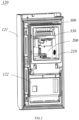
Figure 2 is a schematic diagram of the refrigerator's refrigeration door as shown inFigure 1 ; -
Figure 3 is a schematic diagram of the refrigerator's refrigeration system as shown inFigure 1 ; -
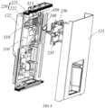
Figure 4 is an exploded view of the refrigeration door as shown inFigure 2 ; -
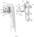
Figure 5 is a partial exploded view of the refrigeration door as shown inFigure 2 ; -
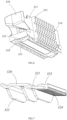
Figure 6 is a three-dimensional schematic diagram of the ice tray according to an embodiment of the present application; -
Figure 7 is a three-dimensional schematic diagram of the cooling plate according to an embodiment of the present application; -
Figure 8 is a schematic diagram of the water receiving tray according to an embodiment of the present application; -
Figure 9 is a schematic diagram of the ice-making device according to another embodiment of the present application. - To enable those skilled in the art to better understand the technical solutions of the present application, the following describes the embodiments of the present application in detail with reference to the accompanying drawings. Clearly, the described embodiments are only a part of the embodiments of the application, not all embodiments. Based on the embodiments of the present application, all other embodiments obtained by those of ordinary skill in the art without creative efforts should fall within the protection scope of the present application.
- Refer to
Figures 1 to 3 , therefrigerator 100 provided in this application comprises acabinet 110 and a door for opening and closing thecabinet 110, the door can be connected to thecabinet 110 through ahinge 500. The storage compartments formed inside thecabinet 110 comprise a refrigeration compartment and a freezing compartment. The door comprises arefrigeration door 120 for opening and closing the refrigeration compartment and a freezing door for the freezing compartment. An ice-makingcompartment 200 can be provided on therefrigeration door 120. Therefrigeration door 120 may comprise adoor shell 121 and adoor liner 122, between which insulating material, can be filled, such as, such as foaming material can be filled between thedoor shell 121 and thedoor liner 122. Thedoor liner 122 of therefrigeration door 120 can directly form the ice-makingcompartment 200 by recessing towards thedoor shell 121, or an ice-making compartment opening can be provided on thedoor liner 122, and an independent ice-making compartment shell 210 can be installed at the opening to form the ice-makingcompartment 200, foaming material can be filled between the ice-makingcompartment shell 210 and thedoor shell 121. - In this embodiment, the
refrigerator 100 may be equipped with arefrigeration system 400, therefrigeration system 400 can comprise acompressor 410, acondenser 420, anevaporator 440, andrefrigerant pipes 450. A two-outletelectromagnetic valve 430 can be connected after thecondenser 420, controlling the direction of the refrigerant flow which is compressed by thecompressor 410 and flows through thecondenser 420, thus forming two parallel refrigerant circuits to thecompressor 410. Theevaporator 440 and therefrigerant pipes 450 are set in the two refrigerant circuits respectively. - In this embodiment, a compressor compartment and an evaporator compartment can be set on a cabinet side, the
compressor 410 and thecondenser 420 can be placed in the compressor compartment, and theevaporator 440 placed in the evaporator compartment. The evaporator compartment can be connected to the refrigeration compartment and freezing compartment through ducts, and a fan can be installed inside the evaporator compartment. Starting the fan can drive the cold air in the evaporator compartment to the refrigeration compartment or freezing compartment. Part of therefrigerant pipes 450 can be placed inside the ice-makingcompartment 200 to directly cool the air inside the ice-makingcompartment 200 and the ice-makingdevice 300. - When the ice-making
compartment 200 is located in therefrigeration door 120, part of therefrigerant pipes 450 can be embedded in the foam layer of therefrigeration door 120, entering the inside of the ice-makingcompartment 200 from the foam layer of therefrigeration door 120. Therefrigerant pipes 450 can be connected to theelectromagnetic valve 430 on thecabinet 110 side through anintake pipe 460 and areturn pipe 470. Theintake pipe 460 and thereturn pipe 470 can be flexible pipes, Theintake pipe 460 and thereturn pipe 470 can pass out from a hinge hole on thecabinet 110 side and then through a hinge shaft on the door side into the space between thedoor liner 122 and thedoor shell 121. Part of thereturn pipe 470 is exposed outside therefrigerator 100, and because of the temperature difference between thereturn pipe 470 and the ambient temperature, condensation is prone to occur where thereturn pipe 470 is exposed outside therefrigerator 100. To reduce condensation, ahinge cover 510 covering theintake pipe 460 and thereturn pipe 470 can be set at thehinge 500, and thehinge cover 510 can be an insulating component. - In this embodiment, the refrigerant from the
compressor 410 can be intermittently supplied to theevaporator 440 and therefrigerant pipes 450, thereby promoting the utilization of cooling and reducing condensation at thereturn pipe 470. - In one embodiment of the present application, the ice-making
compartment 200 is equipped with an ice-makingdevice 300, the ice-makingdevice 300 can comprise anice tray 310 and an ice storage box located below theice tray 310. Therefrigerator 100 can also be equipped with a water supply device, which can automatically supply water to theice tray 310. After the water in theice tray 310 is completely frozen, the ice from theice tray 310 can fall into the ice storage box below for user access. - Refer to
Figures 4 to 7 , theice tray 310 may comprise aside wall 311 and abottom wall 312. One of theside wall 311 of theice tray 310 is provided with several firstheat exchange ribs 313. Therefrigerant pipe 450 is installed on thebottom wall 312 and theside wall 311 of theice tray 310 to be in thermal contact with both thebottom wall 312 and theside wall 311. The cooling of therefrigerant pipe 450 can be directly transferred to thebottom wall 312 and theside wall 311 of theice tray 310. Meanwhile, through the firstheat exchange ribs 313 on theside wall 311 of theice tray 310, the cooling can be directly dissipated into the interior of the ice-makingcompartment 200, lowering the internal temperature of the ice-makingcompartment 200 to ensure that the ice cubes in the ice storage box do not melt. Thus, it is possible to increase the heat exchange between therefrigerant pipe 450, the ice-making compartment 200, and theice tray 310, enhancing the cooling utilization rate of therefrigerant pipe 450, speeding up ice making efficiency, and reducing condensation at thereturn pipe 470. - Further, in one embodiment of this application, the first
heat exchange ribs 313 abut against a wall of the ice-makingcompartment 200. A firstpipe installation groove 314 is provided on the firstheat exchange ribs 313, therefrigerant pipe 450 placed within the firstpipe installation groove 314 and between the wall of the ice-makingcompartment 200 and theside wall 311 of theice tray 310. Foaming material fills the space between the ice-makingcompartment 200 and thedoor shell 121. When the ice-makingcompartment 200 is formed by an independent ice-makingcompartment shell 210, foaming material fills between the ice-makingcompartment shell 210 and thedoor shell 121. Since parts of therefrigerant pipe 450 are placed within the foaming material and parts within the ice-makingcompartment 200, directly setting the firstpipe installation groove 314 on the firstheat exchange ribs 313 for installing therefrigerant pipe 450 facilitates manufacturing and assembly, while avoiding exposure of therefrigerant pipe 450 inside the ice-makingcompartment 200, eliminating the need for additional components to shield therefrigerant pipe 450. Moreover, direct contact between therefrigerant pipe 450 and the firstheat exchange ribs 313 can enhance the efficiency of cooling transfer. - During the foaming process of the refrigeration door, parts of the
refrigerant pipe 450 can be pre-installed between thedoor liner 122 and thedoor shell 121, fixed by foaming material, and then therefrigerant pipe 450 inside the ice-makingcompartment 200 is assembled with theice tray 310. Theside wall 311 of theice tray 310 can be directly installed on a wall of the ice-makingcompartment 200 through screws or other fasteners, thus, therefrigerant pipe 450 can also be directly fixed between the wall of the ice-makingcompartment 200 and theice tray 310. - Further, in one embodiment of this application, the first
heat exchange ribs 313 extend in the vertical direction of theice tray 310, the extension direction of therefrigerant pipe 450 perpendicular to the extension direction of the firstheat exchange ribs 313. In this embodiment, several firstheat exchange ribs 313 can be set parallel to each other, each provided with a firstpipe installation groove 314, and several firstpipe installation grooves 314 on the firstheat exchange ribs 313 can be correspondingly set, so that at the same height, several firstheat exchange ribs 313 are provided with corresponding firstpipe installation grooves 314. In the vertical direction, several rows of parallel firstpipe installation grooves 314 are set on the firstheat exchange ribs 313, therefrigerant pipe 450 extending through each row of firstpipe installation grooves 314 in a serpentine shape, and the primary extension direction of therefrigerant pipe 450 is perpendicular to the extension direction of the firstheat exchange ribs 313. This facilitates extending therefrigerant pipe 450 to the bottom of theice tray 310, easing overall manufacturing and assembly. - Further, in one embodiment of this application, the
bottom wall 312 of theice tray 310 is provided with a secondpipe installation groove 315, and the bottom of theice tray 310 is also provided with acooling plate 320. Thecooling plate 320 is provided with a thirdpipe installation groove 321, therefrigerant pipe 450 placed within both the secondpipe installation groove 315 and the thirdpipe installation groove 321 and fixed at the bottom of theice tray 310 by thecooling plate 320. - In this embodiment, the
bottom wall 312 of theice tray 310 may only have one secondpipe installation groove 315, therefrigerant pipe 450 bent in a serpentine shape, therefrigerant pipe 450 comprising multiple sections extending along the length of theice tray 310. These sections can be installed within the secondpipe installation groove 315 and fixed at the bottom of theice tray 310 by thecooling plate 320. Thecooling plate 320 can be made from aluminum or other high thermal conductivity materials. Thecooling plate 320 can promote the transfer of cooling capacity. Thecooling plate 320 is provided with a thirdpipe installation groove 321, which may have multiple segments to match each section extending along the length of theice tray 310, securing and positioning therefrigerant pipe 450. - Further, in one embodiment of this application, the bottom of the
ice tray 310 may also be equipped with adefrosting heating wire 340. After the completion of ice making, thedefrosting heating wire 340 can be activated to heat the bottom of theice tray 310 to assist in separating the ice cubes from theice tray 310, facilitating subsequent defrosting. In this embodiment, thebottom wall 312 of theice tray 310 may have a defrosting heatingwire installation groove 316, the space between theside wall 311 of theice tray 310 and the secondpipe installation groove 315 forming the defrosting heatingwire installation groove 316. In horizontal plane, thedefrosting heating wire 340 may be U-shaped, both sides of the U-shapeddefrosting heating wire 340 placed within the defrosting heatingwire installation groove 316. Thecooling plate 320 is also provided with a defrosting heating wireaccommodating groove 323, the defrosting heating wireaccommodating groove 323 located on one side edge of thecooling plate 320 and parallel to the thirdpipe installation groove 315. One side of the U-shaped defrosting heating wire can be placed within the defrosting heating wireaccommodating groove 323, allowing the heat from thedefrosting heating wire 340 to be transmitted through the cooling plate to the entire bottom of theice tray 310, ensuring a more even distribution of heat. - The side of the
cooling plate 320 away from theice tray 310, may be provided with a secondheat exchange rib 322 located below the thirdpipe installation groove 315 and a thirdheat exchange rib 324 located below the defrosting heatingwire installation groove 316. The extension direction of the secondheat exchange rib 322 is parallel to the extension direction of the thirdpipe installation groove 315, while the thirdheat exchange rib 324 is perpendicular to the secondheat exchange rib 322. This configuration can increase the density of the thirdheat exchange rib 324, allowing the cooling capacity of therefrigerant pipe 450 to radiate between theice tray 310 and thewater receiving component 330, thereby enhancing the heat exchange rate. Additionally, during the defrosting process, the heat from thedefrosting heating wire 340 can radiate between theice tray 310 and thewater receiving component 330, facilitating the melting of frozen water inside thewater receiving component 330 for expulsion from the refrigerator. - The ice-making
device 300 also comprises awater receiving component 330 placed below theice tray 310. During the defrosting process, activating thedefrosting heating wire 340 might cause condensation at the bottom of theice tray 310 or on thecooling plate 320. During the ice-making process or the water supply process, droplets might also fall from theice tray 310 or thecooling plate 320. Thewater receiving component 330 can collect droplets falling from theice tray 310 or thecooling plate 320, preventing the droplets from entering the ice storage box and causing the ice cubes within to stick together. - A drainage outlet can be set on a wall of the ice-making
compartment 200, and a drainage pipe connecting the drainage outlet and the external environment of therefrigerator 100 can be set within the foaming layer of therefrigeration door 120. Refer toFigure 8 , thewater receiving component 330 may have adrainage nozzle 332, thedrainage nozzle 332 can cooperate with thewater receiving component 330. Droplets entering thewater receiving component 330 are expelled through thedrainage nozzle 332 into the drainage pipe and then out of the unit. - Refer to
Figure 9 , thewater receiving component 330 can comprise awater receiving tray 331 and a thermalconductive plate 333 placed inside thewater receiving tray 331. A heating wire can be set on a side of the thermalconductive plate 333 away from theice tray 310. The thermalconductive plate 333 can be made from aluminum plate or other high thermal conductivity materials. The heating wire can prevent water inside thewater receiving tray 331 from freezing, and setting the heating wire between thewater receiving tray 331 and the thermalconductive plate 333 can prevent the heating wire from being exposed on the outside. The thermalconductive plate 333 can then transmit the heat from the heating wire across the entire bottom surface of the water receiving tray, increasing the radiation area of the heating wire. - The
water receiving tray 331 can be an insulating shell. During the defrosting process, the temperature increase of therefrigerant pipe 450 can raise the temperature inside the ice-makingcompartment 200, and because therefrigerant pipe 450 is close to the ice storage box, the increased temperature of therefrigerant pipe 450 can easily cause the ice cubes in the ice storage box to melt. Thus, it can prevent excessive temperature rise in the ice-makingcompartment 200 and melting of the ice cubes in the ice storage box. - The
drainage nozzle 332 can be set on thewater receiving tray 331, two ends of thewater receiving tray 331 may be opening. Thedrainage nozzle 332 can be positioned in the middle of thewater receiving tray 331, the bottom surface of thewater receiving tray 331 sloped towards the location of thedrainage nozzle 332 to direct water in thewater receiving tray 331 towards thedrainage nozzle 332 for expulsion. The other two sides of thewater receiving tray 331 can be provided with baffles, which can connect to the wall of the ice-makingcompartment 200 and theice tray 310, thereby securing thewater receiving component 330 relative to theice tray 310. - In another embodiment of this application, the
water receiving component 330 may not comprise the aluminum plate and heating wire, but instead, directly extend thedefrosting heating wire 340 into thewater receiving component 330. A portion of thedefrosting heating wire 340 can be installed in the defrosting heatingwire installation groove 316 at the bottom of theice tray 310, with another portion extending between the coolingplate 320 and thewater receiving component 330, directly utilizing the heat from thedefrosting heating wire 340 to prevent water inside thewater receiving component 330 from freezing. Of course, the thermalconductive plate 333 and the heating wire can also be set, with thedefrosting heating wire 340 extending between thewater receiving component 330 and thecooling plate 320. - In this embodiment, in horizontal plane, the
defrosting heating wire 340 can be bent in a U-shape to be installed at the bottom of theice tray 310, both sides of the U-shapeddefrosting heating wire 340 can be placed on the two sides at the bottom of theice tray 310. In vertical plane, thedefrosting heating wire 340 can also be bent in a U-shape, both sides of the U-shaped wire can be placed within the defrosting heatingwire installation groove 316 at the bottom of theice tray 310 and between the coolingplate 320 and thewater receiving component 330. Thus, without the need for additional heating wires, utilizing the heat from thedefrosting heating wire 340 can simultaneously achieve defrosting and prevent water inside thewater receiving tray 331 from freezing, making the overall structure more compact. - Furthermore, as seen in
Figures 4 and5 , in one embodiment of the application, the wall of the ice-makingcompartment 200 has an installation opening 220, aninstallation bracket 230 is set at the installation opening 220. Insulating foam is filled between theinstallation bracket 230 and thedoor shell 121. Theside wall 311 of theice tray 310 is connected to theinstallation bracket 230, apipe inlet slot 233 and apipe outlet slot 234 are provided on one side of theinstallation bracket 230. Therefrigerant pipe 450 enters the ice-makingcompartment 200 through thepipe inlet slot 233 and exits through thepipe outlet slot 234. - In this embodiment, the ice-making
compartment 200 can have a rear wall opposite the opening side of therefrigerator cabinet 110, and two side walls. The installation opening 220 can be opened on the rear wall of the ice-makingcompartment shell 210. The length direction of theice tray 310 may parallel to the width direction of the door, the height direction of theice tray 310 may parallel to the height direction of the door, and the width direction of theice tray 310 may parallel to the thickness direction of the door. Along the length direction of theice tray 310, thepipe inlet slot 233 and thepipe outlet slot 234 can be located on the same side of theice tray 310, facilitating the installation of therefrigerant pipe 450 during the subsequent foaming manufacturing process of the door. In the height direction of theice tray 310, thepipe inlet slot 233 and thepipe outlet slot 234 are located at both ends of theice tray 310. Therefrigerant pipe 450 can enter through thepipe inlet slot 233 into the firstpipe installation groove 314, exit from the firstpipe installation groove 314 into the secondpipe installation groove 315 at the bottom of theice tray 310, and finally, from the secondpipe installation groove 315 exit through thepipe outlet slot 234 back into the foaming layer between the ice-makingcompartment shell 210 and thedoor shell 121. Naturally, thepipe inlet slot 233 may correspond to the secondpipe installation groove 315, and thepipe outlet slot 234 may correspond to the firstpipe installation groove 314. - Further, in this embodiment of the application, an installation opening 220 also provided with a fixing
bracket 240, apipe fixing groove 241 matching thepipe inlet slot 233 andpipe outlet slot 234 can be provided on the fixingbracket 240. Thepipe fixing grooves 241, which can be two in number, work together with theinstallation bracket 230 such that thepipe inlet slot 233 andpipe outlet slot 234 cooperate with thepipe fixing grooves 241 to form ducts slot that match the diameter of therefrigerant pipe 450. - The installation opening 220 comprises a
first opening 221 opened on a rear wall of the ice-makingcompartment 200 and a second opening 222 set on a side wall of the ice-makingcompartment 200. Thefirst opening 221 connects to the second opening 222. Theinstallation bracket 230 comprises aside bracket 231 matching thefirst opening 221 and abottom bracket 232 perpendicular to theside bracket 231. Thebottom bracket 232 and the fixingbracket 240 are set at the second opening 222, and the assemble of the fixingbracket 240 and thebottom bracket 232 can be match the shape of the second opening 222, theconnection surface 242 of the fixingbracket 240 to the side wall of the ice-makingcompartment 200 can be inclined. Theside bracket 231 forms part of the rear wall of the ice-makingcompartment 200, and both thebottom bracket 232 and the fixingbracket 240 form part of the side wall of the ice-makingcompartment 200. -
Support feet 235 are also set on theside bracket 231 of theinstallation bracket 230, thesupport feet 235 can abut against thedoor shell 121. During the manufacturing process of therefrigerator 100's door, theintake pipe 460 and returnpipe 470 can first be threaded through the hinge shaft on thedoor shell 121 into thedoor shell 121. After bending therefrigerant pipe 450 into a predetermined shape to connect with theintake pipe 460 and returnpipe 470, theinstallation bracket 230 can be pre-installed on thedoor shell 121, such as by preliminarily connecting thesupport feet 235 to thedoor shell 121 with double-sided tape, placing the predetermined part of therefrigerant pipe 450 into thepipe inlet slot 233 andpipe outlet slot 234, and then mounting the fixingbracket 240 on theinstallation bracket 230 to preliminarily fix therefrigerant pipe 450 in place, preventing it from shifting during the subsequent door foaming process. Then, the ice-makingcompartment shell 210 is pre-installed on thedoor liner 122, and after combining thedoor liner 122 with thedoor shell 121, foaming material is injected. Thus, both theinstallation bracket 230 and the fixingbracket 240 can be further fixed by the foaming material. Moreover, theconnection surface 242 of the fixingbracket 240 to the side wall of the ice-makingcompartment 200 being inclined makes it easier for the fixingbracket 240 to match with thedoor liner 122 during the foaming process, and can reduce the leakage of foaming material. - It should be understood that although the specification is described in accordance with the embodiments, not every embodiment contains only a single independent technical solution, and this narration is only for clarity. Those skilled in the art should consider the specification as a whole, and the technical solutions in the embodiments can also be appropriately combined to form other embodiments understood by those skilled in the art. The detailed explanations listed above are only specific explanations for feasible embodiments of the application and are not intended to limit the scope of the application. Any equivalent embodiments or changes made without departing from the spirit of the application should be comprised within the scope of the application.
Claims (10)
- A refrigerator, comprising:an ice-making compartment, wherein an ice-making device is provided within the ice-making compartment, the ice-making device comprising an ice tray;a refrigerant pipe, part of the refrigerant pipe being located within the ice-making compartment;characterized in that, the ice tray comprises a side wall and a bottom wall, one of the side wall of the ice tray is provided with a plurality of first heat exchange ribs, the refrigerant pipe is installed on the side wall and the bottom wall of the ice tray.
- The refrigerator according to claim 1, wherein one of the side wall of the ice tray is connected to a wall of the ice-making compartment, the first heat exchange ribs abut against the wall of the ice-making compartment, and a first pipe installation groove is provided on the first heat exchange rib, the refrigerant pipe is placed within the first pipe installation groove.
- The refrigerator according to claim 2, wherein the first heat exchange ribs extend in a height direction of the ice tray, an extension direction of the refrigerant pipe is perpendicular to an extension direction of the first heat exchange rib.
- The refrigerator according to claim 2, wherein a second pipe installation groove is provided on the bottom wall of the ice tray, a cooling plate is provided at the bottom of the ice tray, the cooling plate is provided with a third pipe installation groove, the refrigerant pipe is located within the second pipe installation groove and the third pipe installation groove and is fixed at the bottom of the ice tray by the cooling plate.
- The refrigerator according to claim 4, wherein a defrosting heating wire accommodating groove is set on the cooling plate, the defrosting heating wire accommodating groove is located at one side edge of the cooling plate and parallel to the second pipe installation groove, a side of the cooling plate away from the ice tray is provided with a second heat exchange rib located below the third pipe installation groove and a third heat exchange rib located below the defrosting heating wire accommodating groove, an extension direction of the second heat exchange rib is the same as an extension direction of the third pipe installation groove, the third heat exchange rib is perpendicular to the second heat exchange rib.
- The refrigerator according to claim 4, further comprising a water receiving component, the water receiving component is located below the ice tray, the water receiving component comprises a water receiving tray and a thermal conducting plate placed within the water receiving tray, the thermal conducting plate is provided with a heating wire on a side away from the ice tray.
- The refrigerator according to claim 4, further comprising a water receiving component, the water receiving component is located below the ice tray, a defrosting heating wire installation groove is also provided on the bottom wall of the ice tray, part of the defrosting heating wire is placed within the defrosting heating wire installation groove, and part extends between the cooling plate and the water receiving component.
- The refrigerator according to claim 1, wherein the refrigerator comprises a cabinet, a storage compartment formed inside the cabinet comprises a refrigeration compartment and a freezing compartment, the cabinet is connected with a refrigeration door for opening and closing the refrigeration compartment, the ice-making compartment is formed within the refrigeration door, a compressor is set on a cabinet side, a refrigerant inlet end of the refrigerant pipe is connected with a side of the compressor through an intake pipe, a refrigerant outlet end of the refrigerant pipe is connected with a side of the compressor through a return pipe, both the intake pipe and the return pipe extend from a cabinet side to a refrigeration door side, the refrigeration door comprises a door shell and a door liner, an ice-making compartment is provided on a door liner side, insulating material fills between the door shell, the door liner, and the ice-making compartment shell, another part of the refrigerant pipe is placed between the door shell and the door liner.
- The refrigerator according to claim 8, wherein a wall of the ice-making compartment is provided with an installation opening, an installation bracket is set at the installation opening, insulating foam fills between the installation bracket and the door shell, the side wall of the ice tray is connected to the installation bracket, one side of the installation bracket is provided with a pipe inlet groove and a pipe outlet groove, the refrigerant pipe enters the ice-making compartment from the pipe inlet groove and exits the ice-making compartment from the pipe outlet groove.
- The refrigerator according to claim 9, wherein a fixing bracket is also set at the installation opening, the fixing bracket is provided with pipe fixing grooves matching the pipe inlet groove and the pipe outlet groove; the installation opening comprises a first opening set on the rear wall of the ice-making compartment and a second opening set on the side wall of the ice-making compartment, the first opening is connected with the second opening, the installation bracket comprises a side bracket matching the first opening and a bottom bracket perpendicular to the side bracket, the bottom bracket and the fixing bracket are set at the second opening, the assemble of the fixing bracket and the bottom bracket matches the shape of the second opening, the connection surface of the fixing bracket with the side wall of the ice-making compartment is inclined.
Applications Claiming Priority (2)
| Application Number | Priority Date | Filing Date | Title |
|---|---|---|---|
| CN202122807095.6U CN217541184U (en) | 2021-11-16 | 2021-11-16 | Refrigerator with a door |
| PCT/CN2022/130925 WO2023088150A1 (en) | 2021-11-16 | 2022-11-09 | Refrigerator |
Publications (2)
| Publication Number | Publication Date |
|---|---|
| EP4435354A1 true EP4435354A1 (en) | 2024-09-25 |
| EP4435354A4 EP4435354A4 (en) | 2025-02-26 |
Family
ID=83418123
Family Applications (1)
| Application Number | Title | Priority Date | Filing Date |
|---|---|---|---|
| EP22894687.7A Pending EP4435354A4 (en) | 2021-11-16 | 2022-11-09 | FRIDGE |
Country Status (3)
| Country | Link |
|---|---|
| EP (1) | EP4435354A4 (en) |
| CN (1) | CN217541184U (en) |
| WO (1) | WO2023088150A1 (en) |
Families Citing this family (1)
| Publication number | Priority date | Publication date | Assignee | Title |
|---|---|---|---|---|
| CN217541184U (en) * | 2021-11-16 | 2022-10-04 | 青岛海尔电冰箱有限公司 | Refrigerator with a door |
Family Cites Families (10)
| Publication number | Priority date | Publication date | Assignee | Title |
|---|---|---|---|---|
| KR101504233B1 (en) * | 2010-01-04 | 2015-03-20 | 삼성전자 주식회사 | Refrigerator |
| US20110252816A1 (en) * | 2010-04-14 | 2011-10-20 | Whirlpool Corporation | Refrigerator icemaker moisture removal and defrost assembly |
| KR101658674B1 (en) * | 2010-07-02 | 2016-09-21 | 엘지전자 주식회사 | Ice storing apparatus and control method therof |
| KR101981680B1 (en) * | 2013-10-16 | 2019-05-23 | 삼성전자주식회사 | Ice making tray and refrigerator having the same |
| US10712069B2 (en) * | 2017-07-07 | 2020-07-14 | Bsh Home Appliances Corporation | Compact ice making system having two part ice tray portion |
| US11181309B2 (en) * | 2017-12-22 | 2021-11-23 | Electrolux Home Products, Inc. | Direct cooling ice maker |
| US10539354B2 (en) * | 2017-12-22 | 2020-01-21 | Electrolux Home Products, Inc. | Direct cooling ice maker |
| CN110285621A (en) * | 2019-07-19 | 2019-09-27 | 李传炉 | Evaporator of an ice maker |
| CN214581960U (en) * | 2020-12-25 | 2021-11-02 | 青岛海尔智能技术研发有限公司 | Ice-making unit and refrigerating and freezing device with same |
| CN217541184U (en) * | 2021-11-16 | 2022-10-04 | 青岛海尔电冰箱有限公司 | Refrigerator with a door |
-
2021
- 2021-11-16 CN CN202122807095.6U patent/CN217541184U/en active Active
-
2022
- 2022-11-09 EP EP22894687.7A patent/EP4435354A4/en active Pending
- 2022-11-09 WO PCT/CN2022/130925 patent/WO2023088150A1/en not_active Ceased
Also Published As
| Publication number | Publication date |
|---|---|
| WO2023088150A8 (en) | 2024-04-18 |
| CN217541184U (en) | 2022-10-04 |
| EP4435354A4 (en) | 2025-02-26 |
| WO2023088150A1 (en) | 2023-05-25 |
Similar Documents
| Publication | Publication Date | Title |
|---|---|---|
| US9175893B2 (en) | Refrigerator | |
| CA2670334C (en) | Refrigerator | |
| CN216716636U (en) | Evaporator, air duct assembly and refrigeration equipment | |
| CN216716716U (en) | Air duct assembly and refrigeration equipment | |
| CN222364234U (en) | Refrigerating appliance | |
| EP4435354A1 (en) | Refrigerator | |
| CN114719513B (en) | Ice making assembly and refrigerator | |
| CN107514864A (en) | Door body superconduction ice maker and there is its refrigerator | |
| CN221992160U (en) | Refrigerating appliance | |
| WO2022037437A1 (en) | Air-cooled refrigerator with evaporator arranged at bottom of cabinet | |
| CN117824252A (en) | Air-cooled horizontal freezer | |
| CN214537002U (en) | Ice-making components and refrigerators | |
| CN115031457A (en) | Ice maker and refrigeration equipment | |
| EP4435353A1 (en) | Refrigerator and refrigerator manufacturing method | |
| CN222364232U (en) | Refrigerating appliance | |
| CN222418117U (en) | Refrigerating appliance | |
| CN222364233U (en) | Refrigerating appliance | |
| CN222865316U (en) | Refrigerating appliance | |
| JP7819325B2 (en) | Refrigeration equipment | |
| CN222849549U (en) | Refrigerating appliance | |
| CN108387052A (en) | The air-cooled vertical refrigeration equipment of multi-temperature zone | |
| CN108168190A (en) | Air cooling refrigeration equipment | |
| CN120444823A (en) | Refrigerating appliance | |
| WO2025167675A1 (en) | Refrigeration appliance | |
| CN120444831A (en) | Refrigerating appliance |
Legal Events
| Date | Code | Title | Description |
|---|---|---|---|
| STAA | Information on the status of an ep patent application or granted ep patent |
Free format text: STATUS: THE INTERNATIONAL PUBLICATION HAS BEEN MADE |
|
| PUAI | Public reference made under article 153(3) epc to a published international application that has entered the european phase |
Free format text: ORIGINAL CODE: 0009012 |
|
| STAA | Information on the status of an ep patent application or granted ep patent |
Free format text: STATUS: REQUEST FOR EXAMINATION WAS MADE |
|
| 17P | Request for examination filed |
Effective date: 20240327 |
|
| AK | Designated contracting states |
Kind code of ref document: A1 Designated state(s): AL AT BE BG CH CY CZ DE DK EE ES FI FR GB GR HR HU IE IS IT LI LT LU LV MC ME MK MT NL NO PL PT RO RS SE SI SK SM TR |
|
| DAV | Request for validation of the european patent (deleted) | ||
| DAX | Request for extension of the european patent (deleted) | ||
| A4 | Supplementary search report drawn up and despatched |
Effective date: 20250128 |
|
| RIC1 | Information provided on ipc code assigned before grant |
Ipc: F25C 5/08 20060101ALI20250122BHEP Ipc: F25C 1/04 20180101ALI20250122BHEP Ipc: F25D 23/00 20060101ALI20250122BHEP Ipc: F25D 23/12 20060101ALI20250122BHEP Ipc: F25D 11/02 20060101AFI20250122BHEP |