EP4435310A1 - Hydraulic couplings - Google Patents
Hydraulic couplings Download PDFInfo
- Publication number
- EP4435310A1 EP4435310A1 EP24161051.8A EP24161051A EP4435310A1 EP 4435310 A1 EP4435310 A1 EP 4435310A1 EP 24161051 A EP24161051 A EP 24161051A EP 4435310 A1 EP4435310 A1 EP 4435310A1
- Authority
- EP
- European Patent Office
- Prior art keywords
- connector
- connectors
- hydraulic
- coupling arrangement
- male
- Prior art date
- Legal status (The legal status is an assumption and is not a legal conclusion. Google has not performed a legal analysis and makes no representation as to the accuracy of the status listed.)
- Pending
Links
Images

Classifications
-
- F—MECHANICAL ENGINEERING; LIGHTING; HEATING; WEAPONS; BLASTING
- F16—ENGINEERING ELEMENTS AND UNITS; GENERAL MEASURES FOR PRODUCING AND MAINTAINING EFFECTIVE FUNCTIONING OF MACHINES OR INSTALLATIONS; THERMAL INSULATION IN GENERAL
- F16L—PIPES; JOINTS OR FITTINGS FOR PIPES; SUPPORTS FOR PIPES, CABLES OR PROTECTIVE TUBING; MEANS FOR THERMAL INSULATION IN GENERAL
- F16L37/00—Couplings of the quick-acting type
- F16L37/004—Couplings of the quick-acting type using magnets
-
- F—MECHANICAL ENGINEERING; LIGHTING; HEATING; WEAPONS; BLASTING
- F16—ENGINEERING ELEMENTS AND UNITS; GENERAL MEASURES FOR PRODUCING AND MAINTAINING EFFECTIVE FUNCTIONING OF MACHINES OR INSTALLATIONS; THERMAL INSULATION IN GENERAL
- F16L—PIPES; JOINTS OR FITTINGS FOR PIPES; SUPPORTS FOR PIPES, CABLES OR PROTECTIVE TUBING; MEANS FOR THERMAL INSULATION IN GENERAL
- F16L37/00—Couplings of the quick-acting type
- F16L37/08—Couplings of the quick-acting type in which the connection between abutting or axially overlapping ends is maintained by locking members
-
- F—MECHANICAL ENGINEERING; LIGHTING; HEATING; WEAPONS; BLASTING
- F16—ENGINEERING ELEMENTS AND UNITS; GENERAL MEASURES FOR PRODUCING AND MAINTAINING EFFECTIVE FUNCTIONING OF MACHINES OR INSTALLATIONS; THERMAL INSULATION IN GENERAL
- F16L—PIPES; JOINTS OR FITTINGS FOR PIPES; SUPPORTS FOR PIPES, CABLES OR PROTECTIVE TUBING; MEANS FOR THERMAL INSULATION IN GENERAL
- F16L37/00—Couplings of the quick-acting type
- F16L37/56—Couplings of the quick-acting type for double-walled or multi-channel pipes or pipe assemblies
Definitions
- Embodiments of the present invention relate generally to push-fit, quick-connect hydraulic couplings having a male connector for insertion into a female connector and which are suitable for use on utility vehicles having a hydraulic supply system, such as tractors and construction vehicles.
- Many utility vehicles have a hydraulic supply system which is used to supply hydraulic fluid under pressure to hydraulic consumers on the vehicle. It is also known to use the hydraulic supply system on a utility vehicle to provide hydraulic fluid to consumers on an implement which is temporarily attached to the vehicle. Such implements may be towed by the vehicle or mounted to a hitch on the vehicle, for example.
- push-fit, quick-connect hydraulic couplings having a male connector which is inserted into a female connector.
- the female connector of each coupling is provided on the vehicle and the male coupling is attached to an end of a hydraulic pipe on the implement.
- female connecters are integrated into a valve block on the vehicle having a number of hydraulic valves located side-by-side for controlling hydraulic consumers on an attached implement.
- Two couplings are typically provided for each valve, one coupling forming part of a supply line through which hydraulic fluid is provided from the vehicle to the implement and the other forming part of a return line through which hydraulic fluid is returned from the implement to the vehicle when the valve is open.
- Push-fit, quick-connect couplings have a mechanical locking arrangement which is engaged once the male connector has been inserted into the female connector to hold the male connector in engagement in the female connector.
- the mechanical locking arrangement typically has a biasing arrangement which must be overcome to insert the male connector sufficiently to engage the locking arrangement.
- the force required to insert the male connector into the female connector can be uncomfortably high, thus rendering connection of the coupling problematic. This is a particular issue where a user is required to engage a number of couplings in order to hydraulically connect an implement to the hydraulic supply system on a vehicle.
- a hydraulic coupling arrangement including at least one push-fit, quick-connect hydraulic coupling comprising a male connector and a female connector each defining a longitudinal axis and where the male connector is configured for insertion into the female connector in an axial direction parallel to the longitudinal axes of the connectors, the arrangement including an electromagnetic actuator device located externally of the connectors, the arrangement configured such that with the connectors positioned for insertion of the male connector into the female connector, activation of the electromagnetic actuator is operative to draw the male connector into the female connector.
- the electromagnetic actuator may comprise an electromagnetic coil external to but associated with one connector and a support member carrying the other connector, the support member comprising a magnetically attractive component for interaction with the coil, the arrangement configured such that with the connectors positioned for insertion of the male connector into the female connector, activation of the coil is operative to move the magnetically attractive component, the support member and the other connector in the axial direction to assist in the insertion of the male connector into the female connector.
- a hydraulic coupling arrangement including at least one push-fit, quick-connect hydraulic coupling comprising a male connector and a female connector each defining a longitudinal axis and where the male connector is configured for insertion into the female connector in an axial direction parallel to the longitudinal axes of the connectors, the arrangement also including an electromagnetic coil external to but associated with one connector and a support member carrying the other connector, the support member comprising a magnetically attractive component for interaction with the coil, the arrangement configured such that with the connectors positioned for insertion of the male connector into the female connector, activation of the coil is operative to move the magnetically attractive component, the support member and the other connector in the axial direction to assist in the insertion of the male connector into the female connector.
- the magnetically attractive component may be a metal component and may be a ferromagnetic metal component.
- the electromagnetic coil is typically located in a fixed position relative to the one connector and in use is actuated with the male and female connectors aligned for insertion. Once actuated, the electromagnetic coil attracts the magnetically attractive component and helps to draw the male connector into the female connector. This overcomes at least some of the bias force of the locking arrangement so that the user does not have to apply as much force as with a conventional, unassisted coupling. Once the locking arrangement is engaged, the electromagnetic coil can be deactivated, relying on the mechanical locking arrangement to keep the male connector engaged in the female connector in the usual way. Thus electrical power need be provided to the electromagnetic coil only during the engagement process.
- the electromagnetic coil and support member with the magnetically attractive component are external to the connectors and so the connectors do not require any internal modification. This enables use of otherwise standard push-fit, quick action coupling connectors.
- the magnetically attractive component may be a projection shaped for insertion into the electromagnetic coil and may have a longitudinal axis aligned parallel to the longitudinal axis of the other connector.
- the arrangement may be configured such that the projection is aligned for insertion in the electromagnetic coil when the connectors are aligned for insertion of the male connector into the female connector.
- the support member may carry the male connector, with the longitudinal axis of the projection being aligned parallel to but offset from the longitudinal axis of the male connector.
- the coupling arrangement comprises at least two push-fit, quick-connect couplings, each coupling including a respective male and female connector, wherein the support member carries the other connector of each of the couplings, the arrangement configured such that with the connectors of each coupling aligned for insertion of the male connector into their respective female connector, activation of the electromagnetic coil is operative to draw the magnetically attractive component, the support member and the other connectors in the axial direction to assist in the insertion of the male connectors into the female connectors.
- the coupling arrangement comprises two push-fit, quick-connect couplings
- the electromagnetic coil is located adjacent, and optionally between, the female connectors of the couplings and the male connectors are carried by the support member
- the magnetically attractive component comprises a metallic projection aligned with its longitudinal axis parallel to the longitudinal axes of the male connectors.
- the arrangement is configured such that with the male connectors each aligned for insertion in their respective female connector, the projection is aligned for insertion in the electromagnetic coil such that activation of the electromagnetic coil is operative to draw the projection into the coil and to draw the male connectors into their respective female connectors.
- the hydraulic coupling arrangement may have an actuator system for activating the electromagnetic coil, in which the actuator system comprises an electrical circuit including a manually operable switch for activating the coil.
- the hydraulic coupling arrangement may be configured for use with a utility vehicle, the, or each, one connector and the electromagnetic coil being mounted to the utility vehicle.
- the support member may be provided as part of an implement attachable to the utility vehicle.
- the hydraulic coupling arrangement has an actuator system for activating the electromagnetic coil, in which the actuator system comprises an electrical circuit including a manually operable switch for activating the coil, the electrical circuit may operate using an algorithm which ensures that the electromagnetic coil can only be activated when at least one condition is met.
- the at least one condition may be indicative that the utility vehicle is in a park mode.
- the actuator system may include an electronic controller, which may be a programmable controller, configured to operate according to the algorithm.
- a combination of a utility vehicle and an implement attached to the utility vehicle comprising a hydraulic coupling arrangement according to the previous aspect of the disclosure.
- The, or each, one connector may form part of a hydraulic supply system of the utility vehicle and the, or each, other connector may form part of a hydraulic circuit on the implement.
- the utility vehicle may be a tractor.
- the implement may be an agricultural implement.
- the coupling arrangement may comprise two push-fit quick-connect hydraulic couplings, one coupling forming part of a supply line for supplying hydraulic fluid from the utility vehicle to a hydraulic consumer on the implement, the other coupling forming part of a return line for returning hydraulic fluid from the consumer on the implement to the utility vehicle.
- a method of using the coupling arrangement comprising, with the connectors positioned for insertion of the male connector into the female connector, activating the electromagnetic coil to draw the draw the magnetically attractive component, the support member and the other connector in the axial direction to assist in the insertion of the male connector into the female connector and subsequently deactivating the coil once the male connector is inserted into and coupled with the female connector.
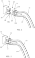
- FIGS. 1 and 2 show diagrammatic representations of a hydraulic coupling arrangement 10 in which two push-fit, quick-connect hydraulic couplings 11, 12 are associated with a hydraulic valve 13.
- the valve 13 in this embodiment may be located towards the rear of a tractor 14 (see FIG. 5 ) or similar utility vehicle.
- the couplings 11, 12 can be used to connect a hydraulic supply system on the vehicle with a hydraulic circuit on an implement which is attached to the tractor 14 so that a hydraulic consumer on the implement can be supplied with hydraulic fluid under pressure from the supply system on the vehicle when the valve 13 is opened.
- One of the couplings 11 forms part of a supply line through which hydraulic fluid is supplied to the hydraulic consumer and includes a female supply connector 11a and a male supply connector 11b.
- the other hydraulic coupling 12 forms part of a return line through which fluid is returned from the hydraulic consumer to the vehicle and includes a female return connector 12a and a male return connector 12b.
- the female connectors 11a, 12a form part of the hydraulic supply system on the vehicle and are fluidly connected respectively with a pump or other source of pressurised hydraulic fluid and a fluid tank or reservoir on the vehicle through the valve 13.
- the male supply and return connectors 11b, 12b form part of an hydraulic circuit on the implement and are connected with the hydraulic consumer via respective fluid pipes 16, 17.
- FIG. 1 the couplings 11, 12 are shown disconnected and in FIG. 2 connected.
- the push-fit, quick-action couplings 11, 12 each have a mechanical locking arrangement which is engaged once the male connector 11b, 12b has been correctly inserted into the female connector 11a, 12a to hold the male connector in engagement in the female connector.
- Such push-fit, quick coupling or fast couplers may be constructed in accordance with standards ISO 7241, ISO 5675 or ISO 16028, for example.
- the coupling arrangement 10 includes an electromagnetic actuator which can be activated to help draw the male connectors 11b, 12b into the female connectors 11a, 12b to reducer the effort required by a user to establish the hydraulic connection.
- the two male connectors 11b, 12b are mounted on a support member in the form of plate 18 which carries a projection 19.
- the projection 19 extends parallel to, and offset from, the longitudinal axes of the male connectors 11b, 12b.
- An electromagnetic coil 20 is positioned between the female connectors 11a, 12b and has a longitudinal axis which is aligned parallel to longitudinal axes of the female connectors 11a, 12a.
- the electromagnetic coil 20 may be mounted to the valve 13 or in some other location fixed relative to the female connectors 11a, 12a.
- the arrangement is configured such that with the male connectors 11b, 12b aligned ready to be inserted in the female connectors 11a, 12b, (that is to say, with the longitudinal axes of the male and female connectors of each coupling 11, 12 co-axial) the projection 19 is aligned for insertion in the electromagnetic coil 20 as shown in FIG. 1 .
- At least the projection 19 of the support member 18 is made of a magnetically attractive material which may be a metallic material including a ferromagnetic metal.
- actuation of the electromagnetic coil draws the projection 19 into the coil 20 moving the male connectors 11b, 12b towards and into the female connectors 11a, 12a in an axial direction parallel to the longitudinal axes of the connectors and helping to engage the male connectors 11b, 12b in their respective female connectors 11a, 12b.
- the electromagnetic attraction helps to overcome the resilient bias force of the locking arrangements of the couplings. Thus, the user does not have to manually overcome all of the bias force which makes insertion easier.
- the male connectors 11b, 12b may be partially inserted in the female connectors 11a, 12a before the electromagnetic coil 20 is actuated to draw the male connectors 11b, 12b further into the female connectors 11a, 12a so as to fully engage the male and female connectors and establish a fluid connection between them.
- the electromagnetic coil 20 can be deactivated and the couplings are 11, 12 held together mechanically in the usual way.
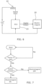
- FIG. 6 shows a schematic diagram of an electrical circuit 21 for the activation of the electromagnetic coil 20 via a switch 22 and, optionally, an electronic control unit 23.
- the electrical control unit 23 may operate a software algorithm shown diagrammatically in FIG. 7 , which checks whether at least one condition is met before allowing the coil 20 to be activated.
- the software algorithm checks whether the tractor 14 is in a parked condition before allowing the electromagnetic coil 20 to be activated. A parked condition may be confirmed if inputs to the electrical control unit 23 from various sensors or other control circuits of the vehicle 14 indicate that the tractor is in neutral and a parking brake applied for example.
- the ECU 23 permits the electromagnetic coil 20 to be activated when the switch 22 is pressed.
- the switch 22 can be conveniently located at the rear of the tractor adjacent the valve block 13 so as to be easily accessible by a user inserting the male connectors 11b, 12b into the female connectors 11a, 12a.
- each hydraulic coupling arrangement 10 comprises two quick-connect couplings 11, 12 which are part of a supply line and return line to a hydraulic consumer respectively.
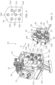
- a valve block 30 consisting of three hydraulic valves 31 to 33 arranged side-by-side is provided.
- Each valve is associated with a pair of push-fit, quick-connect hydraulic couplings so that the coupling arrangement includes three female supply connectors 31a, 32a and 33a and three female return connectors 31b, 32b and 33b respectively with three electromagnetic coils 31c, 32c and 33c, each coil positioned between a respective pair of supply and return female connectors.
- These female connectors mate with corresponding male supply and return connectors 31a', 31b'; 32a', 32b' and 33a', 33b' carried on a support plate 34 having handles 35.
- Each of the male connectors is connected to a respective associated hydraulic line 36, 37; 38, 39; 40, 41 forming part of a hydraulic circuit of an implement attached to the vehicle 14.
- the plate 34 also carries magnetically attractive projections 31d, 32d and 33d (see FIG. 4 ) which interact with coils 31c, 32c and 33c respectively.
- Activation of the electromagnetic coils 31c, 32c and 33c is controlled via a single switch 22 through an electrical circuit similar to that shown in FIG. 6 .
- the switch 22 is closed and the coils are activated as the plate 34 is moved towards the valve block 30 so that the projections 31d, 32d and 33d are drawn into their respective coils 31c, 32c and 33c to assist in the insertion of the male connectors 31a', 31b'; 32a',32b'; 33a',33b' into the female connectors 31a, 31b; 32a,32b; 33a,33b.
- the switch 22 may be located at the rear of the tractor adjacent the valve block 30 so as to be easily accessible by a user inserting the male connectors into the female connectors.
- an electromagnetic coil 31c, 32c, 33c and projection 31d, 32d, 33d are provided for each valve, and hence each pair of couplings, in the embodiment as shown in FIGS. 3 and 4 , it is possible that only two or even one electromagnetic coil and a corresponding number of projection(s) could be used, provided the arrangement can generate sufficient force to draw the male connectors into their respective female connectors when the coil or coils is/are activated.
- FIGS. 3 and 4 enables supply and return couplings for a number of valves, in this case three valves 31, 32, 33, to be connected at the same time.
- the supply and return male connectors for at least one of the valves 31, 32, 33 can be provided on a separate support plate 34 with its own projection 31d, 32d, 33d so that the couplings for this valve can be connected and disconnected independently of the others.
- a single switch 22 may be used to control all of the electromagnetic coils 31c, 32c, 33c or each coil may be independently actuatable by a respective switch 22.
- FIGS. 3 and 4 illustrate a valve block 30 with three valves 31, 32, 33
- the general principles can be adapted for use with valve blocks having any number of valves, including valve blocks with 2, 3, 4, 5, 6, 7, and more valves.
- each valve may be provided with a separate coupling arrangement 10 or at least some of the valves in the valve block may have a combined coupling arrangement 10' similar to that shown in FIGS. 3 and 4 .
- the connectors on the vehicle which will usually be the female connectors 11a, 12a; 31a, 32a, 33a, need not be located on or immediately adjacent a respective valve. Rather, the (usually female) connectors 11a, 12a; 31a, 32a, 33a,33b could be located remotely from their respective valve 13; 31, 32, 33 and connected fluidly to respective ports of the valve.
- the fluid connection could be achieved in any suitable way, for example by way of fluid passages in hydraulic lines (flexible or rigid) or in a casting or other rigid component mounted to the valve, for example.
- the present disclosure thus provides a hydraulic, quick-connect coupling arrangement in which the insertion of a male connector into a female connector is assisted by an electromagnetic actuator in an inexpensive and efficient manner.
- the projections 11b, 12b, 31d, 32d, 33d on the support plate 18, 34 are made of a magnetically attractive material, in some embodiments the plate 18, 34 itself may also be made of, or incorporate, or be coated with, a magnetically attractive material.
Landscapes
- Engineering & Computer Science (AREA)
- General Engineering & Computer Science (AREA)
- Mechanical Engineering (AREA)
- Details Of Connecting Devices For Male And Female Coupling (AREA)
- Quick-Acting Or Multi-Walled Pipe Joints (AREA)
Abstract
Description
- Embodiments of the present invention relate generally to push-fit, quick-connect hydraulic couplings having a male connector for insertion into a female connector and which are suitable for use on utility vehicles having a hydraulic supply system, such as tractors and construction vehicles.
- Many utility vehicles have a hydraulic supply system which is used to supply hydraulic fluid under pressure to hydraulic consumers on the vehicle. It is also known to use the hydraulic supply system on a utility vehicle to provide hydraulic fluid to consumers on an implement which is temporarily attached to the vehicle. Such implements may be towed by the vehicle or mounted to a hitch on the vehicle, for example. In order to temporarily connect the hydraulic supply system on the vehicle with a hydraulic circuit on the implement, it is known to use push-fit, quick-connect hydraulic couplings having a male connector which is inserted into a female connector. Usually, the female connector of each coupling is provided on the vehicle and the male coupling is attached to an end of a hydraulic pipe on the implement. In some known arrangements, female connecters are integrated into a valve block on the vehicle having a number of hydraulic valves located side-by-side for controlling hydraulic consumers on an attached implement. Two couplings are typically provided for each valve, one coupling forming part of a supply line through which hydraulic fluid is provided from the vehicle to the implement and the other forming part of a return line through which hydraulic fluid is returned from the implement to the vehicle when the valve is open.
- Push-fit, quick-connect couplings have a mechanical locking arrangement which is engaged once the male connector has been inserted into the female connector to hold the male connector in engagement in the female connector. The mechanical locking arrangement typically has a biasing arrangement which must be overcome to insert the male connector sufficiently to engage the locking arrangement. The force required to insert the male connector into the female connector can be uncomfortably high, thus rendering connection of the coupling problematic. This is a particular issue where a user is required to engage a number of couplings in order to hydraulically connect an implement to the hydraulic supply system on a vehicle.
- In an aspect of the invention there is provided a hydraulic coupling arrangement including at least one push-fit, quick-connect hydraulic coupling comprising a male connector and a female connector each defining a longitudinal axis and where the male connector is configured for insertion into the female connector in an axial direction parallel to the longitudinal axes of the connectors, the arrangement including an electromagnetic actuator device located externally of the connectors, the arrangement configured such that with the connectors positioned for insertion of the male connector into the female connector, activation of the electromagnetic actuator is operative to draw the male connector into the female connector.
- The electromagnetic actuator may comprise an electromagnetic coil external to but associated with one connector and a support member carrying the other connector, the support member comprising a magnetically attractive component for interaction with the coil, the arrangement configured such that with the connectors positioned for insertion of the male connector into the female connector, activation of the coil is operative to move the magnetically attractive component, the support member and the other connector in the axial direction to assist in the insertion of the male connector into the female connector.
- In another aspect of the invention, there is provided a hydraulic coupling arrangement including at least one push-fit, quick-connect hydraulic coupling comprising a male connector and a female connector each defining a longitudinal axis and where the male connector is configured for insertion into the female connector in an axial direction parallel to the longitudinal axes of the connectors, the arrangement also including an electromagnetic coil external to but associated with one connector and a support member carrying the other connector, the support member comprising a magnetically attractive component for interaction with the coil, the arrangement configured such that with the connectors positioned for insertion of the male connector into the female connector, activation of the coil is operative to move the magnetically attractive component, the support member and the other connector in the axial direction to assist in the insertion of the male connector into the female connector.
- The magnetically attractive component may be a metal component and may be a ferromagnetic metal component.
- The electromagnetic coil is typically located in a fixed position relative to the one connector and in use is actuated with the male and female connectors aligned for insertion. Once actuated, the electromagnetic coil attracts the magnetically attractive component and helps to draw the male connector into the female connector. This overcomes at least some of the bias force of the locking arrangement so that the user does not have to apply as much force as with a conventional, unassisted coupling. Once the locking arrangement is engaged, the electromagnetic coil can be deactivated, relying on the mechanical locking arrangement to keep the male connector engaged in the female connector in the usual way. Thus electrical power need be provided to the electromagnetic coil only during the engagement process. The electromagnetic coil and support member with the magnetically attractive component are external to the connectors and so the connectors do not require any internal modification. This enables use of otherwise standard push-fit, quick action coupling connectors.
- The magnetically attractive component may be a projection shaped for insertion into the electromagnetic coil and may have a longitudinal axis aligned parallel to the longitudinal axis of the other connector. The arrangement may be configured such that the projection is aligned for insertion in the electromagnetic coil when the connectors are aligned for insertion of the male connector into the female connector.
- The support member may carry the male connector, with the longitudinal axis of the projection being aligned parallel to but offset from the longitudinal axis of the male connector.
- In an embodiment, the coupling arrangement comprises at least two push-fit, quick-connect couplings, each coupling including a respective male and female connector, wherein the support member carries the other connector of each of the couplings, the arrangement configured such that with the connectors of each coupling aligned for insertion of the male connector into their respective female connector, activation of the electromagnetic coil is operative to draw the magnetically attractive component, the support member and the other connectors in the axial direction to assist in the insertion of the male connectors into the female connectors.
- In an embodiment, the coupling arrangement comprises two push-fit, quick-connect couplings, the electromagnetic coil is located adjacent, and optionally between, the female connectors of the couplings and the male connectors are carried by the support member, the magnetically attractive component comprises a metallic projection aligned with its longitudinal axis parallel to the longitudinal axes of the male connectors. The arrangement is configured such that with the male connectors each aligned for insertion in their respective female connector, the projection is aligned for insertion in the electromagnetic coil such that activation of the electromagnetic coil is operative to draw the projection into the coil and to draw the male connectors into their respective female connectors.
- The hydraulic coupling arrangement may have an actuator system for activating the electromagnetic coil, in which the actuator system comprises an electrical circuit including a manually operable switch for activating the coil.
- The hydraulic coupling arrangement may be configured for use with a utility vehicle, the, or each, one connector and the electromagnetic coil being mounted to the utility vehicle. The support member may be provided as part of an implement attachable to the utility vehicle. Where the hydraulic coupling arrangement has an actuator system for activating the electromagnetic coil, in which the actuator system comprises an electrical circuit including a manually operable switch for activating the coil, the electrical circuit may operate using an algorithm which ensures that the electromagnetic coil can only be activated when at least one condition is met. The at least one condition may be indicative that the utility vehicle is in a park mode. The actuator system may include an electronic controller, which may be a programmable controller, configured to operate according to the algorithm.
- According to a further aspect of the invention, there is provided a combination of a utility vehicle and an implement attached to the utility vehicle, the combination comprising a hydraulic coupling arrangement according to the previous aspect of the disclosure. The, or each, one connector may form part of a hydraulic supply system of the utility vehicle and the, or each, other connector may form part of a hydraulic circuit on the implement. The utility vehicle may be a tractor. The implement may be an agricultural implement. The coupling arrangement may comprise two push-fit quick-connect hydraulic couplings, one coupling forming part of a supply line for supplying hydraulic fluid from the utility vehicle to a hydraulic consumer on the implement, the other coupling forming part of a return line for returning hydraulic fluid from the consumer on the implement to the utility vehicle.
- According to a still further aspect of the invention, there is provided a method of using the coupling arrangement according to either of the first and second aspects set out above, the method comprising, with the connectors positioned for insertion of the male connector into the female connector, activating the electromagnetic coil to draw the draw the magnetically attractive component, the support member and the other connector in the axial direction to assist in the insertion of the male connector into the female connector and subsequently deactivating the coil once the male connector is inserted into and coupled with the female connector.
- Within the scope of this application it should be understood that the various aspects, embodiments, examples and alternatives set out herein, and individual features thereof may be taken independently or in any possible and compatible combination. Where features are described with reference to a single aspect or embodiment, it should be understood that such features are applicable to all aspects and embodiments unless otherwise stated or where such features are incompatible.
- Embodiments of the invention will now be described, by way of example only, with reference to the accompanying drawings, in which:
-
FIG. 1 shows a schematic perspective view of a hydraulic coupling arrangement in accordance with the present invention as applied to a single hydraulic valve in a disconnected state; -
FIG. 2 shows the hydraulic coupling arrangement ofFigure 1 in a connected state; -
FIG. 3 shows a perspective view of a three valve version of a coupling arrangement in accordance the present disclosure in a disconnected state; -
FIG. 4 is a view in the direction of arrow A ofFIG. 3 showing the layout of the male connectors and projections of the coupling arrangement ofFIG. 3 ; -
FIG. 5 shows a side view of a tractor with part of the hydraulic coupling arrangement ofFIG. 1 fitted to a rear housing; -
FIG. 6 shows a schematic diagram of an actuation circuit for an electromagnetic coil used in the hydraulic coupling arrangement of the present disclosure, and -
FIG. 7 illustrates an algorithm which may be used to control actuation of the electromagnetic coil ofFIG. 6 . -
FIGS. 1 and 2 , show diagrammatic representations of ahydraulic coupling arrangement 10 in which two push-fit, quick-connecthydraulic couplings hydraulic valve 13. Thevalve 13 in this embodiment may be located towards the rear of a tractor 14 (seeFIG. 5 ) or similar utility vehicle. Thecouplings tractor 14 so that a hydraulic consumer on the implement can be supplied with hydraulic fluid under pressure from the supply system on the vehicle when thevalve 13 is opened. - One of the
couplings 11 forms part of a supply line through which hydraulic fluid is supplied to the hydraulic consumer and includes afemale supply connector 11a and amale supply connector 11b. The otherhydraulic coupling 12 forms part of a return line through which fluid is returned from the hydraulic consumer to the vehicle and includes afemale return connector 12a and amale return connector 12b. Thefemale connectors valve 13. The male supply andreturn connectors respective fluid pipes - In
FIG. 1 thecouplings FIG. 2 connected. - As is well known in the art, the push-fit, quick-
action couplings male connector female connector - The
coupling arrangement 10 includes an electromagnetic actuator which can be activated to help draw themale connectors female connectors - In the embodiment shown in
FIGS. 1 and 2 , the twomale connectors plate 18 which carries aprojection 19. Theprojection 19 extends parallel to, and offset from, the longitudinal axes of themale connectors electromagnetic coil 20 is positioned between thefemale connectors female connectors - The
electromagnetic coil 20 may be mounted to thevalve 13 or in some other location fixed relative to thefemale connectors male connectors female connectors coupling projection 19 is aligned for insertion in theelectromagnetic coil 20 as shown inFIG. 1 . At least theprojection 19 of thesupport member 18 is made of a magnetically attractive material which may be a metallic material including a ferromagnetic metal. With the coupling arrangement positioned as shown inFIG. 1 , actuation of the electromagnetic coil draws theprojection 19 into thecoil 20 moving themale connectors female connectors male connectors female connectors male connectors female connectors electromagnetic coil 20 is actuated to draw themale connectors female connectors - Once the
male connectors female connectors electromagnetic coil 20 can be deactivated and the couplings are 11, 12 held together mechanically in the usual way. -
FIG. 6 shows a schematic diagram of an electrical circuit 21 for the activation of theelectromagnetic coil 20 via aswitch 22 and, optionally, anelectronic control unit 23. When present, theelectrical control unit 23 may operate a software algorithm shown diagrammatically inFIG. 7 , which checks whether at least one condition is met before allowing thecoil 20 to be activated. In an embodiment, the software algorithm checks whether thetractor 14 is in a parked condition before allowing theelectromagnetic coil 20 to be activated. A parked condition may be confirmed if inputs to theelectrical control unit 23 from various sensors or other control circuits of thevehicle 14 indicate that the tractor is in neutral and a parking brake applied for example. - Thus if the
tractor 14 is parked and in a safe condition to connect the implement hydraulically to the vehicle, theECU 23 permits theelectromagnetic coil 20 to be activated when theswitch 22 is pressed. Theswitch 22 can be conveniently located at the rear of the tractor adjacent thevalve block 13 so as to be easily accessible by a user inserting themale connectors female connectors - Typically, each
hydraulic coupling arrangement 10 comprises two quick-connect couplings FIGS. 3 and 4 which show a further embodiment of a coupling arrangement 10' accordance with the present disclosure. - In this exemplary embodiment, a
valve block 30 consisting of threehydraulic valves 31 to 33 arranged side-by-side is provided. Each valve is associated with a pair of push-fit, quick-connect hydraulic couplings so that the coupling arrangement includes threefemale supply connectors female return connectors electromagnetic coils connectors 31a', 31b'; 32a', 32b' and 33a', 33b' carried on asupport plate 34 having handles 35. Each of the male connectors is connected to a respective associatedhydraulic line vehicle 14. Theplate 34 also carries magneticallyattractive projections FIG. 4 ) which interact withcoils - Activation of the
electromagnetic coils single switch 22 through an electrical circuit similar to that shown inFIG. 6 . Thus, theswitch 22 is closed and the coils are activated as theplate 34 is moved towards thevalve block 30 so that theprojections respective coils male connectors 31a', 31b'; 32a',32b'; 33a',33b' into thefemale connectors - The
switch 22 may be located at the rear of the tractor adjacent thevalve block 30 so as to be easily accessible by a user inserting the male connectors into the female connectors. - Though an
electromagnetic coil projection FIGS. 3 and 4 , it is possible that only two or even one electromagnetic coil and a corresponding number of projection(s) could be used, provided the arrangement can generate sufficient force to draw the male connectors into their respective female connectors when the coil or coils is/are activated. - The embodiment illustrated in
FIGS. 3 and 4 enables supply and return couplings for a number of valves, in this case threevalves valves separate support plate 34 with itsown projection single switch 22 may be used to control all of theelectromagnetic coils respective switch 22. - Though
FIGS. 3 and 4 illustrate avalve block 30 with threevalves separate coupling arrangement 10 or at least some of the valves in the valve block may have a combined coupling arrangement 10' similar to that shown inFIGS. 3 and 4 . - It should also be appreciated that the connectors on the vehicle, which will usually be the
female connectors connectors respective valve 13; 31, 32, 33 and connected fluidly to respective ports of the valve. The fluid connection could be achieved in any suitable way, for example by way of fluid passages in hydraulic lines (flexible or rigid) or in a casting or other rigid component mounted to the valve, for example. - The present disclosure thus provides a hydraulic, quick-connect coupling arrangement in which the insertion of a male connector into a female connector is assisted by an electromagnetic actuator in an inexpensive and efficient manner. Whilst at least the
projections support plate plate
Claims (12)
- A hydraulic coupling arrangement (10; 10') comprising at least one push-fit, quick-connect hydraulic coupling (11, 12) comprising:a male connector (11b, 12b; 31a', 31b', 32a', 32b', 33a', 33b') and a female connector (11a, 12a; 31a, 31b, 32a, 32b, 33a, 33b) each defining a longitudinal axis, wherein the male connector is configured for insertion into the female connector in an axial direction parallel to the longitudinal axes of the connectors,characterized in the arrangement including an electromagnetic actuator (18, 19, 20; 34, 31c, 32c, 33c, 31d, 32d, 33d) located externally of the connectors, wherein when the connectors are positioned for insertion of the male connector into the female connector the electromagnetic actuator is operative to draw the male connector into the female connector when activated.
- A hydraulic coupling arrangement (10; 10') according to claim 1, wherein the electromagnetic actuator device comprises an electromagnetic coil (20; 31c, 32c, 33c) external to and associated with one connector (11a, 12a; 31a, 31b, 32a, 32b, 33a, 33b) and a support member (18; 34) carrying the other connector (11b, 12b; 31a', 31b', 32a', 32b', 33a', 33b'), the support member comprising a magnetically attractive component (19; 31d, 32d, 33d) for interaction with the coil, the arrangement configured such that with the connectors positioned for insertion of the male connector into the female connector, the coil is operative when activated to draw the magnetically attractive component, the support member and the other connector in the axial direction to assist in the insertion of the male connector into the female connector.
- A hydraulic coupling arrangement (10; 10') according to claim 2, wherein the magnetically attractive component is an elongate projection (19; 31d, 32d, 33d) shaped for insertion into the electromagnetic coil (20; 31c, 32c, 33c), the projection having a longitudinal axis aligned parallel to the longitudinal axis of the other connector, the arrangement configured such that the projection (19; 31d, 32d, 33d) is aligned for insertion in the electromagnetic coil (20; 31c, 32c, 33c) when the connectors are positioned for insertion of the male connector into the female connector.
- A hydraulic coupling arrangement (10; 10') according to claim 3, wherein support member (18; 34) carries the male connector (11b, 12b; 31a', 31b', 32a', 32b', 33a', 33b'), the longitudinal axis of the projection being aligned parallel to and offset from the longitudinal axis of the male connector.
- A hydraulic coupling arrangement (10; 10') according to any one of claims 2 to 4, the coupling arrangement comprising at least two push-fit, quick-connect couplings (10, 11), wherein the support member (18; 34) carries the other connector (11b, 12b; 31a', 31b', 32a', 32b', 33a', 33b') of each of the couplings, wherein the electromagnetic coil is operative to draw the magnetically attractive component, the support member and the other connectors in the axial direction to assist in insertion of the male connectors into the female connectors.
- A hydraulic coupling arrangement (10; 10') according to any one of claims 2 to 5 comprising an actuator system configured to activate the electromagnetic coil (20; 31c, 32c, 33c), in which the actuator system comprises an electrical circuit (21) including a manually operable switch (22) for activating the coil.
- A hydraulic coupling arrangement (10; 10') according to any one of claims 2 to 6 for use with a utility vehicle (14), the, or each, one connector (11a, 12a; 31a, 31b, 32a, 32b, 33a, 33b) and the electromagnetic coil (20; 31c, 32c, 33c) being mounted to the utility vehicle.
- A hydraulic coupling arrangement (10; 10') according to claim 7, wherein the support member (18; 34) is provided as part of an implement attachable to the utility vehicle.
- A hydraulic coupling arrangement (10; 10') according to claim 7 or claim 8, each when dependent on claim 6, in which the electrical circuit (21) is configured to operate using an algorithm such that the electromagnetic coil (20; 31c, 32c, 33c) can only be activated when at least one condition is met, wherein optionally the condition is indicative of the utility vehicle (14) being in a park mode.
- A combination of a utility vehicle (14) and an implement attached to the utility vehicle, the combination comprising a hydraulic coupling arrangement (10; 10') according to any one of claims 2 to 9, wherein the, or each, one connector (11a, 12a; 31a, 31b, 32a, 32b, 33a, 33b) forms part of a hydraulic supply system of the utility vehicle and the, or each, other connector (11b, 12b; 31a', 31b', 32a', 32b', 33a', 33b') forms part of a hydraulic circuit on the implement.
- A combination according to claim 10 wherein the hydraulic coupling arrangement (10; 10') is a hydraulic coupling arrangement according to claim 5, wherein the hydraulic coupling arrangement comprises at least one pair of push-fit, quick-connect hydraulic couplings (11, 12), one coupling (11) of the pair forming part of a supply line for supplying hydraulic fluid from the utility vehicle (14) to a hydraulic consumer on the implement, the other coupling (12) of the pair forming part of a return line for returning hydraulic fluid from the consumer on the implement to the utility vehicle.
- A method of using a coupling arrangement (10; 10') according to any one of claims 2 to 9, the method comprising, with the connectors positioned for insertion of the male connector (11b, 12b; 31a', 31b', 32a', 32b', 33a', 33b') into the female connector (11a, 12a; 31a, 31b, 32a, 32b, 33a, 33b), activating the electromagnetic coil (20; 31c, 32c, 33c) to draw the magnetically attractive component (19; 31d, 32d, 33d), the support member (18; 34) and the other connector (11b, 12b; 31a', 31b', 32a', 32b', 33a', 33b') in the axial direction to assist in insertion of the male connector (11b, 12b; 31a', 31b', 32a', 32b', 33a', 33b') into the female connector (11a, 12a; 31a, 31b, 32a, 32b, 33a, 33b) and subsequently deactivating the electromagnetic coil once the male connector is inserted into and mechanically coupled with the female connector.
Applications Claiming Priority (1)
| Application Number | Priority Date | Filing Date | Title |
|---|---|---|---|
| GBGB2304339.1A GB202304339D0 (en) | 2023-03-24 | 2023-03-24 | Hydraulic coupling |
Publications (1)
| Publication Number | Publication Date |
|---|---|
| EP4435310A1 true EP4435310A1 (en) | 2024-09-25 |
Family
ID=86227925
Family Applications (1)
| Application Number | Title | Priority Date | Filing Date |
|---|---|---|---|
| EP24161051.8A Pending EP4435310A1 (en) | 2023-03-24 | 2024-03-04 | Hydraulic couplings |
Country Status (3)
| Country | Link |
|---|---|
| US (1) | US12618500B2 (en) |
| EP (1) | EP4435310A1 (en) |
| GB (1) | GB202304339D0 (en) |
Families Citing this family (1)
| Publication number | Priority date | Publication date | Assignee | Title |
|---|---|---|---|---|
| WO2024020055A2 (en) * | 2022-07-19 | 2024-01-25 | NorthStar Medical Technologies, LLC | Magnetic fluid connector |
Citations (5)
| Publication number | Priority date | Publication date | Assignee | Title |
|---|---|---|---|---|
| EP1088191B1 (en) * | 1998-02-27 | 2006-04-12 | Messer France S.A. | Fill and bleed module for a refrigerating module and a method for filling a refrigerating module |
| US7793987B1 (en) * | 2006-03-24 | 2010-09-14 | Ric Investments, Llc | Magnetic coupling assembly and method of using same |
| CN113339607A (en) * | 2021-04-29 | 2021-09-03 | 北京明德正康医学研究有限公司 | Combination device for connecting fluid passages |
| US20220000693A1 (en) * | 2019-11-23 | 2022-01-06 | Hangzhou Kelui Baotte Intelligent Technology Co., Ltd. | Automatic nursing robot |
| EP2084447B1 (en) * | 2006-12-01 | 2022-06-15 | Nordhydraulic AB | Hydraulic connection |
Family Cites Families (11)
| Publication number | Priority date | Publication date | Assignee | Title |
|---|---|---|---|---|
| US2965136A (en) * | 1958-06-16 | 1960-12-20 | Haloid Xerox Inc | Xerographic developing apparatus |
| US3079178A (en) * | 1959-04-13 | 1963-02-26 | Airaterra | Flush coupling assemblies |
| US3160386A (en) * | 1961-05-15 | 1964-12-08 | Westinghouse Electric Corp | Coupling device |
| SU626301A1 (en) | 1974-04-24 | 1978-09-30 | Ордена Трудового Красного Знамени Институт Горного Дела Им.А.А.Скочинского | Quick-detachable connection for high-pressure hose |
| US4004298A (en) * | 1975-03-31 | 1977-01-25 | Sinai Hospital Of Detroit | Magnetically aligned releasable connector |
| DE102004039857A1 (en) * | 2004-08-17 | 2006-02-23 | Veritas Ag | Coupling device with magnetic lock |
| US20120013117A1 (en) * | 2010-07-15 | 2012-01-19 | Arnon Bernshtein | Magnetic air hose connector |
| US8136844B1 (en) * | 2010-08-25 | 2012-03-20 | Caremed Supply Inc. | Hose connection structure of air mattress |
| EP3256768B1 (en) * | 2015-02-09 | 2019-09-11 | Veeder-Root Company | Breakaway coupling monitoring |
| CN111536346A (en) | 2020-05-06 | 2020-08-14 | 上海电气电站环保工程有限公司 | Electromagnetic quick pipeline connecting structure |
| EP4094660B1 (en) | 2020-06-08 | 2024-07-31 | Guido Valentini | Pneumatic tube or hose for releasable airtight connection to a pneumatic port and respective pneumatic port |
-
2023
- 2023-03-24 GB GBGB2304339.1A patent/GB202304339D0/en not_active Ceased
-
2024
- 2024-03-01 US US18/593,224 patent/US12618500B2/en active Active
- 2024-03-04 EP EP24161051.8A patent/EP4435310A1/en active Pending
Patent Citations (5)
| Publication number | Priority date | Publication date | Assignee | Title |
|---|---|---|---|---|
| EP1088191B1 (en) * | 1998-02-27 | 2006-04-12 | Messer France S.A. | Fill and bleed module for a refrigerating module and a method for filling a refrigerating module |
| US7793987B1 (en) * | 2006-03-24 | 2010-09-14 | Ric Investments, Llc | Magnetic coupling assembly and method of using same |
| EP2084447B1 (en) * | 2006-12-01 | 2022-06-15 | Nordhydraulic AB | Hydraulic connection |
| US20220000693A1 (en) * | 2019-11-23 | 2022-01-06 | Hangzhou Kelui Baotte Intelligent Technology Co., Ltd. | Automatic nursing robot |
| CN113339607A (en) * | 2021-04-29 | 2021-09-03 | 北京明德正康医学研究有限公司 | Combination device for connecting fluid passages |
Also Published As
| Publication number | Publication date |
|---|---|
| US12618500B2 (en) | 2026-05-05 |
| GB202304339D0 (en) | 2023-05-10 |
| US20240318755A1 (en) | 2024-09-26 |
Similar Documents
| Publication | Publication Date | Title |
|---|---|---|
| US12618500B2 (en) | Hydraulic coupling | |
| EP3275746B1 (en) | Trailer brake pilot control circuit and method of control thereof | |
| US20220034436A1 (en) | Multi-coupler manifold with manual and automatic pressure relief | |
| EP3275747B1 (en) | Pneumatic trailer brake circuit with breakaway detection and method thereof | |
| EP3284643A1 (en) | Hydraulic trailer brake circuit for adjustable gain and improved stability | |
| JP2023518023A (en) | Modular electronic braking system | |
| EP1439105B1 (en) | Brake traction control valve | |
| CN110099816B (en) | System for assisting in driving a trailer from an open tipping hydraulic circuit | |
| US20120025487A1 (en) | Coupler for a vehicle | |
| WO2021052622A1 (en) | Hydraulic valve module and method for supplying hydraulic pressure to circuits of a vehicle | |
| EP1538044A3 (en) | Hydraulic trailer brake device | |
| JP5566990B2 (en) | Braking device | |
| JPH0459186B2 (en) | ||
| JP2001065728A (en) | Solenoid valve and hydraulic circuit | |
| CN108925133B (en) | Control device and related method, brake device, controller, and storage medium | |
| CN102834278B (en) | By the device that trailer is connected with tractor truck pressurized air | |
| JPS595646Y2 (en) | Vehicle brake control device | |
| US2290476A (en) | Car coupling system | |
| US20260042434A1 (en) | Electromechanical brake system with pneumatic trailer actuation | |
| JP2004211902A (en) | Tractor transmission | |
| SU1459965A1 (en) | System for controlling motion of articulated tractors | |
| CN119789966A (en) | Device, system and method for automatically establishing a connection between a towing vehicle and a trailer vehicle | |
| JP3567573B2 (en) | Clutch intermittent device | |
| JP2002089699A (en) | Tractor transmission | |
| JP3576331B2 (en) | Transfer control device |
Legal Events
| Date | Code | Title | Description |
|---|---|---|---|
| PUAI | Public reference made under article 153(3) epc to a published international application that has entered the european phase |
Free format text: ORIGINAL CODE: 0009012 |
|
| STAA | Information on the status of an ep patent application or granted ep patent |
Free format text: STATUS: THE APPLICATION HAS BEEN PUBLISHED |
|
| AK | Designated contracting states |
Kind code of ref document: A1 Designated state(s): AL AT BE BG CH CY CZ DE DK EE ES FI FR GB GR HR HU IE IS IT LI LT LU LV MC ME MK MT NL NO PL PT RO RS SE SI SK SM TR |
|
| STAA | Information on the status of an ep patent application or granted ep patent |
Free format text: STATUS: REQUEST FOR EXAMINATION WAS MADE |
|
| 17P | Request for examination filed |
Effective date: 20250325 |
|
| STAA | Information on the status of an ep patent application or granted ep patent |
Free format text: STATUS: EXAMINATION IS IN PROGRESS |
|
| 17Q | First examination report despatched |
Effective date: 20251023 |