EP4435304A1 - Electric valve - Google Patents
Electric valve Download PDFInfo
- Publication number
- EP4435304A1 EP4435304A1 EP22895371.7A EP22895371A EP4435304A1 EP 4435304 A1 EP4435304 A1 EP 4435304A1 EP 22895371 A EP22895371 A EP 22895371A EP 4435304 A1 EP4435304 A1 EP 4435304A1
- Authority
- EP
- European Patent Office
- Prior art keywords
- rotor
- valve
- valve body
- stator
- mounting
- Prior art date
- Legal status (The legal status is an assumption and is not a legal conclusion. Google has not performed a legal analysis and makes no representation as to the accuracy of the status listed.)
- Pending
Links
Images

















Classifications
-
- F—MECHANICAL ENGINEERING; LIGHTING; HEATING; WEAPONS; BLASTING
- F16—ENGINEERING ELEMENTS AND UNITS; GENERAL MEASURES FOR PRODUCING AND MAINTAINING EFFECTIVE FUNCTIONING OF MACHINES OR INSTALLATIONS; THERMAL INSULATION IN GENERAL
- F16K—VALVES; TAPS; COCKS; ACTUATING-FLOATS; DEVICES FOR VENTING OR AERATING
- F16K31/00—Actuating devices; Operating means; Releasing devices
- F16K31/02—Actuating devices; Operating means; Releasing devices electric; magnetic
- F16K31/04—Actuating devices; Operating means; Releasing devices electric; magnetic using a motor
-
- F—MECHANICAL ENGINEERING; LIGHTING; HEATING; WEAPONS; BLASTING
- F25—REFRIGERATION OR COOLING; COMBINED HEATING AND REFRIGERATION SYSTEMS; HEAT PUMP SYSTEMS; MANUFACTURE OR STORAGE OF ICE; LIQUEFACTION SOLIDIFICATION OF GASES
- F25B—REFRIGERATION MACHINES, PLANTS OR SYSTEMS; COMBINED HEATING AND REFRIGERATION SYSTEMS; HEAT PUMP SYSTEMS
- F25B41/00—Fluid-circulation arrangements
- F25B41/30—Expansion means; Dispositions thereof
- F25B41/31—Expansion valves
- F25B41/34—Expansion valves with the valve member being actuated by electric means, e.g. by piezoelectric actuators
- F25B41/35—Expansion valves with the valve member being actuated by electric means, e.g. by piezoelectric actuators by rotary motors, e.g. by stepping motors
-
- H—ELECTRICITY
- H02—GENERATION; CONVERSION OR DISTRIBUTION OF ELECTRIC POWER
- H02K—DYNAMO-ELECTRIC MACHINES
- H02K37/00—Motors with rotor rotating step by step and without interrupter or commutator driven by the rotor, e.g. stepping motors
- H02K37/10—Motors with rotor rotating step by step and without interrupter or commutator driven by the rotor, e.g. stepping motors of permanent magnet type
- H02K37/12—Motors with rotor rotating step by step and without interrupter or commutator driven by the rotor, e.g. stepping motors of permanent magnet type with stationary armatures and rotating magnets
- H02K37/14—Motors with rotor rotating step by step and without interrupter or commutator driven by the rotor, e.g. stepping motors of permanent magnet type with stationary armatures and rotating magnets with magnets rotating within the armatures
-
- H—ELECTRICITY
- H02—GENERATION; CONVERSION OR DISTRIBUTION OF ELECTRIC POWER
- H02K—DYNAMO-ELECTRIC MACHINES
- H02K7/00—Arrangements for handling mechanical energy structurally associated with dynamo-electric machines, e.g. structural association with mechanical driving motors or auxiliary dynamo-electric machines
- H02K7/14—Structural association with mechanical loads, e.g. with hand-held machine tools or fans
-
- H—ELECTRICITY
- H02—GENERATION; CONVERSION OR DISTRIBUTION OF ELECTRIC POWER
- H02K—DYNAMO-ELECTRIC MACHINES
- H02K2213/00—Specific aspects, not otherwise provided for and not covered by codes H02K2201/00 - H02K2211/00
- H02K2213/03—Machines characterised by numerical values, ranges, mathematical expressions or similar information
-
- H—ELECTRICITY
- H02—GENERATION; CONVERSION OR DISTRIBUTION OF ELECTRIC POWER
- H02K—DYNAMO-ELECTRIC MACHINES
- H02K2213/00—Specific aspects, not otherwise provided for and not covered by codes H02K2201/00 - H02K2211/00
- H02K2213/09—Machines characterised by the presence of elements which are subject to variation, e.g. adjustable bearings, reconfigurable windings, variable pitch ventilators
-
- Y—GENERAL TAGGING OF NEW TECHNOLOGICAL DEVELOPMENTS; GENERAL TAGGING OF CROSS-SECTIONAL TECHNOLOGIES SPANNING OVER SEVERAL SECTIONS OF THE IPC; TECHNICAL SUBJECTS COVERED BY FORMER USPC CROSS-REFERENCE ART COLLECTIONS [XRACs] AND DIGESTS
- Y02—TECHNOLOGIES OR APPLICATIONS FOR MITIGATION OR ADAPTATION AGAINST CLIMATE CHANGE
- Y02B—CLIMATE CHANGE MITIGATION TECHNOLOGIES RELATED TO BUILDINGS, e.g. HOUSING, HOUSE APPLIANCES OR RELATED END-USER APPLICATIONS
- Y02B30/00—Energy efficient heating, ventilation or air conditioning [HVAC]
- Y02B30/70—Efficient control or regulation technologies, e.g. for control of refrigerant flow, motor or heating
Definitions
- the present invention relates to an electric valve.
- Patent Literature 1 discloses an example of an electric valve according to the related art.
- the electric valve is installed in a refrigeration cycle system of an air conditioner.
- the electric valve includes a valve body, a valve member, and a stepping motor for moving the valve member.
- the stepping motor includes a rotor and a stator.
- the rotor rotates in response to pulses input to the stepping motor.
- the valve member moves along with the rotation of the rotor, and the movement of the valve member changes an opening degree of a valve port of the valve body.
- a movable stopper fixed to the rotor is in contact with a fixed stopper fixed to the valve body, thereby restricting the rotation of the rotor in a first direction.
- Pulses to be input to the stepping motor correspond to states (excitation patterns) of drive currents to be supplied to the stator.
- the number of the excitation patterns is defined according to a configuration of the stepping motor. Pulses corresponding to the excitation patterns are input to the stepping motor sequentially and cyclically.
- the electric valve is controlled by an electric valve control device.
- the electric valve control device in an initialization operation, inputs pulses to the stepping motor to rotate the rotor in the first direction and positions the rotor at the reference position. Then, the electric valve control device inputs a predetermined number of pulses to the stepping motor to rotate the rotor in a second direction and positions the rotor at a valve opening position.
- the electric valve control device inputs pulses to the stepping motor starting from a pulse corresponding to a specific excitation pattern when positioning the rotor from the reference position to the valve opening position. When the rotor is positioned at the valve opening position, the valve port has the opening degree of a predetermined value.
- Patent Literature 1 Japanese Unexamined Patent Application Publication No. 2020-16247
- the valve body assembly including the valve body and the rotor is manufactured separately from the stator unit including the stator. Then, the stator unit is assembled with the valve body assembly. Electric valves are manufactured such that each of the electric valves has the same number of pulses (a valve opening pulse number) required to rotate the rotor from the reference position to the valve opening position. However, depending on accuracy of components or accuracy of assembling components, the stator may deviate from its correct position around an axis with respect to the valve body assembly when the stator unit is mounted on the valve body.
- an object of the present invention to provide an electric valve capable of decreasing the variation in the valve opening pulse number.
- an electric valve includes a valve body assembly and a stator unit that is mounted on the valve body assembly.
- the valve body assembly includes a valve body that includes a valve seat, a rotor that is rotatable with respect to the valve body, a valve member that faces the valve seat and moves toward the valve seat when the rotor rotates in a first direction, and a stopper mechanism that restricts rotation of the rotor in the first direction when the rotor is at a reference position.
- the stator unit includes a stator that is disposed coaxially with the rotor and constitutes a stepping motor together with the rotor.
- the electric valve includes mounting positions in which the stator unit is mounted on the valve body assembly, and the mounting positions are referred to as stator unit mounting positions.
- ⁇ represents a step angle of the stepping motor
- M represents a number of excitation patterns of the stepping motor
- K represents a number of the stator unit mounting positions
- U represents any integer
- the valve body assembly includes receiving portions corresponding to the stator unit mounting positions.
- the stator unit includes a mounting portion capable of being aligned with any one of the receiving portions.
- the mounting portion is a projection and the receiving portions are recesses or holes, or the mounting portion is a recess or a hole and the receiving portions are projections.
- the stator unit is mounted in one of the stator unit mounting positions corresponding to one of the receiving portions by the mounting portion being secured to the one of the receiving portions.
- the electric valve includes a threaded member with an external thread.
- the valve body assembly includes internal thread holes corresponding to the stator unit mounting positions.
- the stator unit includes a through hole capable of being aligned with any one of the internal thread holes.
- the stator unit is mounted in one of the stator unit mounting positions corresponding to one of the internal thread holes by the threaded member being disposed in the through hole and screwed into the one of the internal thread holes.
- an electric valve includes a valve body, a rotor unit that is mounted on the valve body, and a stator unit that is mounted on the valve body.
- the rotor unit includes a valve seat member that includes a valve seat, a rotor that is rotatable with respect to the valve seat member, a valve member that faces the valve seat and moves toward the valve seat when the rotor rotates in a first direction, and a stopper mechanism that restricts rotation of the rotor in the first direction when the rotor is at a reference position.
- the stator unit includes a stator that is disposed coaxially with the rotor and constitutes a stepping motor together with the rotor.
- the electric valve includes a mounting position in which the stator unit is mounted on the valve body.
- the electric valve includes mounting positions in which the rotor unit is mounted on the valve body, and the mounting positions are referred to as rotor unit mounting positions.
- ⁇ represents a step angle of the stepping motor
- M represents a number of excitation patterns of the stepping motor
- K represents a number of the rotor unit mounting positions
- U represents any integer
- the valve body includes a mounting hole with an internal thread, and the internal thread is disposed on an inner circumferential surface of the mounting hole.
- the rotor unit includes a mounting member with an external thread, the external thread is disposed on an outer circumferential surface of the mounting member and screwed into the internal thread, and the mounting member holds the valve seat member.
- the mounting member is disposed coaxially with the rotor.
- K represents the number of the rotor unit mounting positions
- up to K spacers are located between the valve body and the mounting member, and at least one spacer is located between the valve body and the mounting member.
- the step angle is equal to a rotational angle of the mounting member around the axis corresponding to a thickness per spacer when the external thread is screwed into the internal thread.
- the electric valve includes a threaded member with an external thread.
- the valve body includes internal thread holes corresponding to the rotor unit mounting positions.
- the rotor unit includes a through hole capable of being aligned with any one of the internal thread holes.
- the rotor unit is mounted in one of the rotor unit mounting positions corresponding to one of the internal thread holes by the threaded member being disposed in the through hole and screwed into the one of the internal thread holes.
- the electric valve includes a threaded member with an external thread.
- the rotor unit includes through holes corresponding to the rotor unit mounting positions.
- the valve body includes an internal thread hole capable of being aligned with any one of the through holes.
- the rotor unit is mounted in one of the rotor unit mounting positions corresponding to one of the through holes by the threaded member being disposed in the one of the through holes and screwed into the internal thread hole.
- the electric valve includes the valve body assembly and the stator unit that is mounted on the valve body assembly.
- the electric valve includes the mounting positions in which the stator unit is mounted on the valve body assembly, and the mounting positions are referred to as "stator unit mounting positions".
- ⁇ represents the step angle of the stepping motor
- M represents the number of excitation patterns of the stepping motor
- K represents the number of the stator unit mounting positions
- U represents any integer
- an angle d ⁇ between one stator unit mounting position and another stator unit mounting position next to the one stator unit mounting position around the axis can be prevented from being a multiple of a number that is the number M of the excitation patterns multiplied by the step angle ⁇ . Therefore, the stator unit is mounted on the valve body assembly in another stator unit mounting position instead of the one stator unit mounting position, thereby enabling the position of the rotor when the pulse corresponding to the specific excitation pattern is input to the stepping motor to be changed by a multiple of the step angle ⁇ .
- the step angle ⁇ corresponds to one pulse to be input to the stepping motor.
- valve opening pulse number the number of pulses required for the rotor to rotate from the reference position to the valve opening position
- the stator unit is mounted in another stator unit mounting position instead of the one stator unit mounting position. This enables the valve opening pulse number to be adjusted. Accordingly, it is possible to decrease a variation in the valve opening pulse number among electric valves.
- the electric valve includes the valve body, the rotor unit that is mounted on the valve body, and the stator unit that is mounted on the valve body.
- the electric valve includes the mounting position in which the stator unit is mounted on the valve body.
- the electric valve includes the multiple mounting positions in which the rotor unit is mounted on the valve body, and the mounting positions are referred to as "rotor unit mounting positions".
- ⁇ represents the step angle of the stepping motor
- M represents the number of excitation patterns of the stepping motor
- K represents the number of the rotor unit mounting positions
- U represents any integer
- an angle d ⁇ between one rotor unit mounting position and another rotor unit mounting position next to the one rotor unit mounting position around the axis can be prevented from being a multiple of a number that is the number M of excitation patterns multiplied by the step angle ⁇ . Therefore, the rotor unit is mounted on the valve body in another rotor unit mounting position instead of the one rotor unit mounting position, thereby enabling the position of the rotor when the pulse corresponding to the specific excitation pattern is input to the stepping motor to be changed by a multiple of the step angle ⁇ .
- the step angle ⁇ corresponds to one pulse to be input to the stepping motor.
- valve opening pulse number the number of pulses required for the rotor to rotate from the reference position to the valve opening position
- the rotor unit is mounted in another rotor unit mounting position instead of the one rotor unit mounting position. This enables the valve opening pulse number to be adjusted. Accordingly, it is possible to decrease a variation in the valve opening pulse number among electric valves.
- the electric valve according to a first embodiment of the present invention is described below with reference to Fig. 1 to Fig. 21 .
- the electric valve according to the present embodiment is used as, for example, a flow control valve for controlling the flow rate of refrigerant in a refrigeration cycle system of an air conditioner.
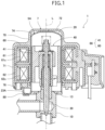
- Fig. 1 is a sectional view of the electric valve according to the first embodiment of the present invention.
- Fig. 2 is an enlarged sectional view of a part (mainly a mounting plate and a mounting tab) of the electric valve in Fig. 1 .
- Fig. 3 is a sectional view of a valve body assembly of the electric valve in Fig. 1 .
- Fig. 4 is a diagram of the valve body assembly in Fig. 3 .
- Fig. 4A is a plan view of the valve body assembly.
- Fig. 4B is an enlarged plan view of a part (mainly the mounting plate) of the valve body assembly.
- Fig. 5 is a diagram of a valve stem holder of the valve body assembly in Fig. 3 .
- FIG. 5A is a perspective view of the valve stem holder.
- Fig. 5B is a plan view of the valve stem holder.
- Fig. 6 is a side view of a guide bush of the valve body assembly in Fig. 3 .
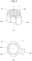
- Fig. 7 is a diagram of a stopper member of the valve body assembly in Fig. 3 .
- Fig. 7A is a perspective view of the stopper member, and
- Fig. 7B is a plan view of the stopper member.
- Fig. 8 is a plan view of the valve stem holder, the stopper member, a rotor, and a stator of the electric valve in Fig. 1 .
- Fig. 8 schematically illustrates the stator.
- Fig. 8 schematically illustrates magnetic poles of the rotor.
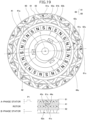
- FIG. 9 is a diagram illustrating a stepping motor of the electric valve in Fig. 1 .
- Fig. 9A schematically illustrates the rotor and coils of the stator.
- Fig. 9B illustrates an example of the correspondence between pulses and drive currents to be supplied to the stator.
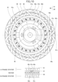
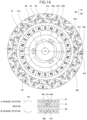
- Fig. 10 to Fig. 21 are diagrams schematically illustrating the positional relationships between the magnetic poles of the rotor and pole teeth of the stator.
- Fig. 10 to Fig. 13 illustrate a configuration in which a valve opening pulse number is a reference number.
- Fig. 14 to Fig. 17 illustrate a configuration in which the valve opening pulse number is more than the reference number by 1.
- Fig. 18 to Fig. 21 illustrate a configuration in which the valve opening pulse number is less than the reference number by 1.
- Fig. 11 , Fig. 15 , and Fig. 19 illustrate states in which pulse P1 is input to the stepping motor.
- Fig. 12 , Fig. 16 , and Fig. 20 illustrate states in which pulse P2 is input to the stepping motor.
- Fig. 13 , Fig. 17 , and Fig. 21 illustrate states in which pulse P3 is input to the stepping motor.
- Fig. 10 to Fig. 21 schematically illustrate the stator.
- Fig. 10 to Fig. 21 schematically illustrate the magnetic poles of the rotor.
- an electric valve 1 As illustrated in Fig. 1 , an electric valve 1 according to the first embodiment includes a valve body assembly 5A and a stator unit 7.
- the valve body assembly 5A includes a valve body 10, a can 20, a mounting plate 23A, a valve member 30, and a driving section 40.
- the valve body 10 includes a body member 11 and a connection member 13.
- the body member 11 has a circular columnar shape.
- the body member 11 includes a valve chamber 14.
- a first conduit 15 and a second conduit 16 are bonded to the body member 11.
- the first conduit 15 is disposed in a direction (lateral direction in Fig. 3 ) perpendicular to an axis L and is connected to the valve chamber 14.
- the second conduit 16 is disposed in a direction of the axis L (up-and-down direction in Fig. 3 ) and is connected to the valve chamber 14 via a valve port 17.
- the valve port 17 is enclosed by a valve seat 18, which has a circular annular shape, in the valve chamber 14.
- the body member 11 includes a fitting hole 11a in a circular shape.
- the fitting hole 11a is in the upper end surface of the body member 11.
- the inner circumferential surface of the fitting hole 11a has a planar surface 11d facing leftward in Fig. 3 .
- a stem hole 11b is provided at the bottom of the fitting hole 11a and communicates with the valve chamber 14.
- the connection member 13 has a circular annular plate-like shape. The inner circumferential edge of the connection member 13 is bonded to the upper end portion of the body member 11.
- the body member 11 and the connection member 13 are made of a metal, such as an aluminum alloy, stainless steel, or brass.
- the can 20 is made of a metal, such as stainless steel.
- the can 20 has a circular cylindrical shape.
- the can 20 is open at the lower end portion and is closed at the upper end portion.
- the lower end portion of the can 20 is bonded to the outer peripheral edge of the connection member 13.
- the mounting plate 23A has a circular arc shape.
- the central angle of the circular arc shape of the mounting plate 23A is approximately 50 degrees.
- the inner edge of the mounting plate 23A is integrally connected to the outer peripheral edge of the connection member 13.
- the connection member 13 and the mounting plate 23A constitute a single component.
- the axis L passes through the center of the circular arc shape of the mounting plate 23A and the center of the connection member 13.
- the mounting plate 23A protrudes radially outward from the connection member 13.
- the mounting plate 23A has multiple holes 24.
- the holes 24 have a circular shape and extend through the mounting plate 23A.
- Each of the holes 24 is a receiving portion.
- the mounting plate 23A has 9 holes 24 (holes 24 [1] to 24[9]).
- the holes 24[1] to 24[9] are on a circle Q1.
- the axis L passes through the center of the circle Q1.
- the valve member 30 includes a first stem portion 31, a second stem portion 32, and a valve portion 33.
- the first stem portion 31 has a circular columnar shape.
- the second stem portion 32 has a circular columnar shape.
- the diameter of the second stem portion 32 is smaller than the diameter of the first stem portion 31.
- the second stem portion 32 is provided coaxially and continuously with the upper end portion of the first stem portion 31.
- the valve member 30 has a step portion 34.
- the step portion 34 is a circular annular plane facing upward.
- the step portion 34 is disposed in the part in which the second stem portion 32 and the first stem portion 31 are continuous with each other.
- the valve portion 33 has a conical shape with a diameter decreasing from top to bottom.
- the valve portion 33 is provided coaxially and continuously with the lower end portion of the first stem portion 31.
- the valve portion 33 is disposed in the valve port 17.
- a variable throttle is formed between the valve portion 33 and the valve port 17.
- the valve portion 33 faces the valve seat 18.
- the rotor 41 has a circular cylindrical shape.
- the outer diameter of the rotor 41 is slightly smaller than the inner diameter of the can 20.
- the rotor 41 is disposed inside the can 20.
- the rotor 41 is rotatable with respect to the valve body 10.
- the rotor 41 has a plurality of north (N) poles and a plurality of south (S) poles.
- the N poles and the S poles are disposed on the outer circumferential surface of the rotor 41.
- the N poles and the S poles extend in the direction of the axis L.
- the N poles and the S poles are alternately arranged at regular angular intervals in the circumferential direction.
- the rotor 41 includes 12 N poles and 12 S poles.
- the angle between adjacent N and S poles is 15 degrees.
- Fig. 5 illustrates the valve stem holder 42.
- the valve stem holder 42 has a circular cylindrical shape.
- the valve stem holder 42 is open at the lower end portion and is closed at the upper end portion.
- the valve stem holder 42 is fitted into a fitting hole 41a of the rotor 41.
- the valve stem holder 42 rotates together with the rotor 41.
- a movable stopper 42s is disposed at the lower end portion on the outer circumferential surface of the valve stem holder 42.
- the movable stopper 42s is a protrusion extending radially outward from the outer circumferential surface of the valve stem holder 42.
- the valve stem holder 42 has a stem hole 42b.
- the stem hole 42b is in an upper wall portion 42a of the valve stem holder 42.
- the second stem portion 32 of the valve member 30 is disposed in the stem hole 42b movably in the direction of the axis L.
- a washer 46 is disposed on the lower surface of the upper wall portion 42a of the valve stem holder 42.
- a valve closing spring 47 is disposed between the step portion 34 of the valve member 30 and the washer 46.
- the valve closing spring 47 is a coil spring and pushes the valve member 30 toward the valve seat 18.
- the inner circumferential surface of the valve stem holder 42 has an internal thread 42c.
- the movable stopper 42s is fixed with respect to the rotor 41.
- Fig. 6 illustrates the guide bush 43.
- the guide bush 43 includes a base portion 43a and a support portion 43b.
- the base portion 43a has a circular cylindrical shape.
- the support portion 43b has a circular cylindrical shape.
- the outer circumferential surface of the base portion 43a has a planar surface 43d.
- the base portion 43a is press-fitted into the fitting hole 11a of the body member 11, and the planar surface 43d is in contact with the planar surface 11d of the fitting hole 11a. Consequently, the central axis of the body member 11 and the central axis of the guide bush 43 are aligned with the axis L, and the guide bush 43 is correctly positioned with respect to the body member 11 around the axis L.
- the outer diameter of the support portion 43b is smaller than the outer diameter of the base portion 43a.
- the inner diameter of the support portion 43b is equal to the inner diameter of the base portion 43a.
- the support portion 43b is provided coaxially and continuously with the upper end portion of the base portion 43a.
- the outer circumferential surface of the support portion 43b has an external thread 43c.
- the external thread 43c is screwed into the internal thread 42c of the valve stem holder 42.
- the first stem portion 31 of the valve member 30 is disposed inside the guide bush 43.
- the guide bush 43 supports the valve member 30 movably in the direction of the axis L.
- Fig. 7 illustrates the stopper member 44.
- the stopper member 44 includes a stopper body 44a.
- the stopper body 44a has a circular cylindrical shape.
- the inner circumferential surface of the stopper body 44a has an internal thread 44c.
- a fixed stopper 44s is disposed on the outer circumferential surface of the stopper body 44a.
- the fixed stopper 44s is a protrusion extending radially outward from the outer circumferential surface of the stopper body 44a.
- the external thread 43c is screwed into the internal thread 44c until the stopper body 44a comes into contact with the base portion 43a of the guide bush 43. This enables the stopper member 44 to be fixed to the guide bush 43.
- the fixed stopper 44s is fixed with respect to the valve body 10.
- the fixed member 45 includes a fixed portion 45a and a flange portion 45b.
- the fixed portion 45a has a stepped circular cylindrical shape.
- the second stem portion 32 of the valve member 30 is disposed inside the fixed portion 45a.
- the fixed portion 45a is bonded to the second stem portion 32.
- the flange portion 45b is provided continuously with the lower end portion of the fixed portion 45a.
- a return spring 48 is disposed such that the return spring 48 encloses the fixed member 45.
- the return spring 48 is a coil spring.
- the stator unit 7 includes a stator 60, a housing 70, and a mounting tab 80.
- the stator 60 has a circular cylindrical shape.
- the stator 60 includes an A-phase stator 61 and a B-phase stator 62.
- the A-phase stator 61 includes a plurality of claw-pole type pole teeth 61a and 61b in the inner circumference. The tip ends of the pole teeth 61a point down, and the tip ends of the pole teeth 61b point up. The pole teeth 61a and the pole teeth 61b are alternately arranged at regular angular intervals in the circumferential direction.
- the A-phase stator 61 includes 12 pole teeth 61a and 12 pole teeth 61b. The angle between adjacent pole teeth 61a and 61b is 15 degrees. When a coil 61c of the A-phase stator 61 is energized, the pole teeth 61a and the pole teeth 61b have mutually opposite polarities.
- the B-phase stator 62 includes a plurality of claw-pole type pole teeth 62a and 62b in the inner circumference. The tip ends of the pole teeth 62a point down, and the tip ends of the pole teeth 62b point up. The pole teeth 62a and the pole teeth 62b are alternately arranged at regular angular intervals in the circumferential direction.
- the B-phase stator 62 includes 12 pole teeth 62a and 12 pole teeth 62b. The angle between adjacent pole teeth 62a and 62b is 15 degrees. When a coil 62c of the B-phase stator 62 is energized, the pole teeth 62a and the pole teeth 62b have mutually opposite polarities.
- the A-phase stator 61 is coaxially disposed on the B-phase stator 62.
- the angle between each of the pole teeth 61a of the A-phase stator 61 and a corresponding adjacent one of the pole teeth 62a of the B-phase stator 62 is 7.5 degrees.
- the B-phase stator 62 is at a position rotated around the axis L by 7.5 degrees with respect to the A-phase stator 61 from a position where the pole teeth 61a are aligned with the pole teeth 62a in the direction of the axis L.
- the coil 61c of the A-phase stator 61 includes terminals A1 and A2.
- the coil 62c of the B-phase stator 62 includes terminals B1 and B2.
- the terminals A1 and A2 and the terminals B1 and B2 are electrically connected to a motor driver (not illustrated).
- the can 20 is disposed inside the stator 60.
- the rotor 41 is disposed inside the can 20.
- the stator 60 and the rotor 41 are members of a stepping motor 66.
- the excitation mode of the stepping motor 66 is 1-2 phase excitation.
- the step angle ⁇ of the stepping motor 66 is 3.75 degrees.
- the step angle ⁇ is a rotational angle per pulse in the stepping motor 66.
- the rotor 41 is rotated by pulses P (P1 to P8) input to the stepping motor 66. Specifically, the rotor 41 is rotated by drive currents, corresponding to pulses P, supplied to the stator 60 of the stepping motor 66.
- the expression “pulses P are input to the stepping motor 66" is synonymous with "drive currents corresponding to pulses P are supplied to the stator 60 of the stepping motor 66".
- Fig. 9B illustrates an example of the correspondence between pulses P1 to P8 and states of drive currents to be supplied to the stator 60 (hereinafter referred to as "excitation patterns").
- excitation patterns states of drive currents to be supplied to the stator 60
- (+) indicates supply of the drive current flowing from the terminal A1 to the terminal A2 or supply of the drive current flowing from the terminal B1 to the terminal B2
- (-) indicates supply of the drive current flowing from the terminal A2 to the terminal A1 or supply of the drive current flowing from the terminal B2 to the terminal B1
- (0) indicates that no drive current is supplied.
- the number M of excitation patterns is 8. Pulses P1 to P8 illustrated in Fig. 9B are input to the stepping motor 66 in order.
- the drive current flowing from the terminal A1 to the terminal A2 is supplied to the coil 61c (+), and no drive current is supplied to the coil 62c (0).
- the drive current flowing from the terminal A1 to the terminal A2 is supplied to the coil 61c (+), and the drive current flowing from the terminal B2 to the terminal B1 is supplied to the coil 62c (-).
- the drive current flowing from the terminal A2 to the terminal A1 is supplied to the coil 61c (-), and the drive current flowing from the terminal B2 to the terminal B1 is supplied to the coil 62c (-).
- the drive current flowing from the terminal A2 to the terminal A1 is supplied to the coil 61c (-), and no drive current is supplied to the coil 62c (0).
- the drive current flowing from the terminal A2 to the terminal A1 is supplied to the coil 61c (-), and the drive current flowing from the terminal B1 to the terminal B2 is supplied to the coil 62c (+).
- the drive current flowing from the terminal A1 to the terminal A2 is supplied to the coil 61c (+), and the drive current flowing from the terminal B1 to the terminal B2 is supplied to the coil 62c (+).
- pulses P are cyclically input to the stepping motor 66 in descending order (in the order from pulse P8 to pulse P1).
- a screw-feed action between the internal thread 42c of the valve stem holder 42 and the external thread 43c of the guide bush 43 moves the rotor 41 and the valve stem holder 42 downward.
- the rotor 41 (the valve stem holder 42) pushes the valve member 30 downward via the valve closing spring 47.
- the valve member 30 moves downward, and the valve portion 33 comes into contact with the valve seat 18.
- the rotor 41 is at a valve closing position Rc.
- the valve closing spring 47 is compressed and the rotor 41 and the valve stem holder 42 further move downward.
- the valve member 30 does not move downward.
- the movable stopper 42s of the valve stem holder 42 comes into contact with the fixed stopper 44s of the stopper member 44, the rotation of the rotor 41 in the first direction is restricted.
- the rotor 41 is at a reference position Rx.
- the movable stopper 42s and the fixed stopper 44s constitute a stopper mechanism 49 that restricts the rotation of the rotor 41 in the first direction.
- pulses P are cyclically input to the stepping motor 66 in ascending order (in the order from pulse P1 to pulse P8).
- the screw-feed action between the internal thread 42c of the valve stem holder 42 and the external thread 43c of the guide bush 43 moves the rotor 41 and the valve stem holder 42 upward.
- the rotor 41 (the valve stem holder 42) pushes the fixed member 45 upward.
- the valve member 30 moves upward together with the fixed member 45 and separates from the valve seat 18.
- the rotor 41 is considered to be at a valve opening position Ro when a fluid flow rate at the valve port 17 (opening degree of the valve port 17) reaches a predetermined value in a predetermined flow-rate measuring environment.
- the predetermined value is set as appropriate according to the configuration and application of the electric valve 1.
- the housing 70 is made of synthetic resin.
- the housing 70 is injection molded.
- the housing 70 houses the stator 60.
- the housing 70 includes a peripheral wall portion 71 and an upper wall portion 72.
- the peripheral wall portion 71 has a circular cylindrical shape.
- the stator 60 is embedded in the peripheral wall portion 71.
- the upper wall portion 72 is provided continuously with the upper end portion of the peripheral wall portion 71.
- the inner circumferential surface of the peripheral wall portion 71, the inner surface of the upper wall portion 72, and the inner circumferential surface of the stator 60 form an inner space 74 of the stator unit 7.
- the can 20 is disposed inside the inner space 74.
- the mounting tab 80 is a rectangular metal plate bent into a crank shape. A first end portion 80a of the mounting tab 80 is caulked to a conductive member 76 embedded in the lower end portion of the peripheral wall portion 71. The mounting tab 80 may be welded to the conductive member 76. The conductive member 76 is electrically connected to a yoke of the B-phase stator 62.
- the mounting tab 80 has a projecting portion 81.
- the projecting portion 81 is disposed at a second end portion 80b of the mounting tab 80. The projecting portion 81 projects upward. The projecting portion 81 is pressed to a lower surface 23a of the mounting plate 23A.
- the projecting portion 81 is a mounting portion.
- the projecting portion 81 can be aligned with any one of the holes 24[1] to 24[9] of the mounting plate 23A. Specifically, when the stator unit 7 is rotated around the axis L clockwise in plan view, the tip end of the projecting portion 81 fits into the holes 24[1] to 24[9] in order. When the tip end of the projecting portion 81 fits into one of the holes 24[1] to 24[9], the projecting portion 81 is secured to the one of the holes 24, and the stator unit 7 is positioned with respect to the valve body assembly 5A.
- the electric valve 1 includes multiple mounting positions in which the stator unit 7 is mounted on the valve body assembly 5A, and the mounting positions are referred to as "stator unit mounting positions".
- the stator unit mounting positions correspond to the holes 24[1] to 24[9].
- the stator unit 7 can be mounted in any one of the stator unit mounting positions.
- the angles of the holes 24[1] to 24[9] around the axis L increase by 3.75 degrees in the first direction.
- An angle around the axis L between the stator unit 7 with the projecting portion 81 aligned with the hole 24[j] and the stator unit 7 with the projecting portion 81 aligned with the hole 24[j + 1] is the angle d ⁇ [j].
- the angle d ⁇ [j] around the axis L between any two holes 24 adjacent to each other is 3.75 degrees. It is sufficient that the angle d ⁇ [j] be a multiple of the step angle ⁇ and satisfy the following expression (1). Respective angles d ⁇ [j] may be different from each other.
- M is the number of excitation patterns.
- U is any integer. d ⁇ j ⁇ M ⁇ ⁇ ⁇ U
- the step angle ⁇ of the stepping motor 66 is 3.75 degrees, the number of the excitation patterns M is 8, and the integer N is 0.
- the respective central axes of the valve body 10 (the body member 11, the connection member 13), the valve port 17, the can 20, the valve member 30, the rotor 41, the valve stem holder 42, the guide bush 43, and the stator 60 (the A-phase stator 61, the B-phase stator 62) are aligned with the axis L.
- the center of the circular arc shape of the mounting plate 23A is also aligned with the axis L.
- the electric valve 1 is controlled by an electric valve control device (not illustrated).
- the electric valve control device inputs, in the initialization operation of the electric valve 1, pulses P1 to P8 to the stepping motor 66 in descending order to rotate the rotor in the first direction and positions the rotor 41 at the reference position Rx. Then, the electric valve control device inputs pulses P1 to P8 to the stepping motor 66 in ascending order to rotate the rotor 41 in the second direction and positions the rotor 41 at the valve opening position Ro.
- the electric valve control device inputs pulses P starting from pulse P1 in positioning the rotor 41 at the valve opening position Ro. Pulse P1 is pulse P corresponding to the specific excitation pattern.
- Fig. 10 illustrates a configuration in which the stator unit 7 is mounted around the axis L in a correct position with respect to the valve body assembly 5A when the projecting portion 81 of the mounting tab 80 is secured to the hole 24 [5] of the mounting plate 23A.
- the magnetic poles of the rotor 41 radially face the pole teeth 61a and 61b of the A-phase stator 61 when the rotor 41 is at the reference position Rx.
- the positional relationship between the rotor 41 and the stator 60 (A-phase stator 61, B-phase stator 62) is described by focusing on one magnetic pole (magnetic pole 41s) of the rotor 41, one pole tooth (pole tooth 61s) of the A-phase stator 61, and one pole tooth (pole tooth 62s) of B-phase stator 62.
- the magnetic pole 41s, the pole tooth 61s, and the pole tooth 62s are marked with a dot for easy understanding of the positional relationship.
- Fig. 14 illustrates a configuration in which the stator unit 7 is mounted in a position where the stator unit 7 is rotated around the axis L by the step angle ⁇ in the first direction from the correct position with respect to the valve body assembly 5A when the projecting portion 81 of the mounting tab 80 is secured to the hole 24 [5] of the mounting plate 23A.
- the magnetic pole 41s of the rotor 41 is at a position where the magnetic pole 41s is rotated by the step angle ⁇ in the second direction from a position where the magnetic pole 41s radially faces the pole tooth 61s of the A-phase stator 61.
- the valve opening pulse number C in this configuration is the reference number Cs plus one. Therefore, the projecting portion 81 is secured to the hole 24[4] instead of the hole 24[5] in the electric valve 1.
- This enables the rotor 41 to be at the reference position Rx and the magnetic poles of the rotor 41 to radially face the pole teeth 61a and the pole teeth 61b of the A-phase stator 61 when pulse P1 is input to the stepping motor 66.
- the rotor 41 is correctly positioned at the valve opening position Ro.
- Fig. 18 illustrates a configuration in which the stator unit 7 is mounted in a position where the stator unit 7 is rotated around the axis L by the step angle ⁇ in the second direction from the correct position with respect to the valve body assembly 5A when the projecting portion 81 of the mounting tab 80 is secured to the hole 24[5] of the mounting plate 23A.
- the magnetic pole 41s of the rotor 41 is at a position where the magnetic pole 41s is rotated by the step angle ⁇ in the first direction from a position where the magnetic pole 41s radially faces the pole tooth 61s of the A-phase stator 61.
- the rotor 41 rotates by the step angle ⁇ in the second direction from the position where the rotor 41 is located in Fig.19 .
- the pole tooth 62s attracts the magnetic pole 41s. Consequently, as illustrated in Fig. 21 , the rotor 41 is positioned at a position where the rotor 41 is rotated by the step angle ⁇ in the second direction from the position where the rotor 41 is located in Fig. 20 , and the magnetic pole 41s radially faces the pole tooth 62s.
- pulses P are cyclically input in ascending order
- the rotor 41 rotates by the step angle ⁇ in the second direction in response to pulse P being input.
- the rotor 41 When the number of pulses P being input reaches the reference number Cs, the rotor 41 is positioned at a position where the angle from the reference position Rx around the axis L is larger than the angle of the valve opening position Ro by the step angle ⁇ . That is, the valve opening pulse number C in this configuration is the reference number Cs minus 1. Therefore, the projecting portion 81 is secured to the hole 24[6] instead of the hole 24[5] in the electric valve 1. This enables the rotor 41 to be at the reference position Rx and the magnetic poles of the rotor 41 to radially face the pole teeth 61a and the pole teeth 61b of the A-phase stator 61 when pulse P1 is input to the stepping motor 66. As a result, when the number of pulses P being input to the stepping motor 66 reaches the reference number Cs, the rotor 41 is correctly positioned at the valve opening position Ro.
- the stator unit mounting position in which the stator unit 7 is mounted is changed, thereby enabling the valve opening pulse number C to vary.
- the valve opening pulse number C of the electric valve 1 can be adjusted to the reference number Cs.
- Fig. 14 to Fig. 17 illustrate a configuration in which the valve opening pulse number C is more than the reference number Cs by 1
- Fig. 18 to Fig. 21 illustrate a configuration in which the valve opening pulse number C is less than the reference number Cs by 1.
- the rotor 41 can be adjusted to be correctly positioned at the valve opening position Ro by changing the hole 24 to which the projecting portion 81 is secured as described above.
- the electric valve 1 has at least the same number of holes 24 as the number M of excitation patterns. It is sufficient that the electric valve 1 have two or more holes 24. For example, if the variation in the valve opening pulse number C among electric valves 1 can be suppressed within ⁇ 1 by increasing accuracy of components and accuracy of assembling components, three holes 24 are enough for the electric valves 1.
- the electric valve 1 includes the valve body assembly 5A and the stator unit 7 that is mounted on the valve body assembly 5A.
- the valve body assembly 5A includes the valve body 10 that includes the valve seat 18, the rotor 41 that is rotatable with respect to the valve body 10, the valve member 30 that faces the valve seat 18 and moves toward the valve seat 18 when the rotor 41 rotates in the first direction, and the stopper mechanism 49 that restricts the rotation of the rotor 41 in the first direction when the rotor is at the reference position Rx.
- the stator unit 7 includes the stator 60 that is disposed coaxially with the rotor 41 and constitutes the stepping motor 66 together with the rotor 41.
- the electric valve 1 includes the mounting positions in which the stator unit 7 is mounted on the valve body assembly 5A, and the mounting positions are referred to as "stator unit mounting positions".
- ⁇ represents the step angle of the stepping motor 66
- M represents the number of excitation patterns of the stepping motor 66
- K represents the number of the stator unit mounting positions
- U represents any integer
- the angle d ⁇ around the axis L between one stator unit mounting position and another stator unit mounting position adjacent to the one stator unit mounting position can be prevented from being a multiple of a number that is the number M of the excitation patterns multiplied by the step angle ⁇ . Therefore, the stator unit 7 is mounted on the valve body assembly 5A in another stator unit mounting position instead of the one stator unit mounting position, thereby enabling the position of the rotor 41 when pulse P corresponding to the specific excitation pattern is input to the stepping motor 66 to be changed by a multiple of the step angle ⁇ .
- the step angle ⁇ corresponds to one pulse P to be input to the stepping motor 66.
- the stator unit 7 is mounted in another stator unit mounting position instead of the one stator unit mounting position. This enables the valve opening pulse number C to be adjusted. Accordingly, it is possible to decrease the variation in the valve opening pulse number C among the electric valves 1.
- the valve body assembly 5A includes the holes 24 corresponding to the stator unit mounting positions.
- the stator unit 7 includes one projecting portion 81 that can be aligned with any one of the holes 24.
- the stator unit 7 is mounted on the valve body assembly 5A in one of the stator unit mounting positions corresponding to one of the holes 24 by the projecting portion 81 being secured to the one of the holes 24.
- the stator unit 7 can be mounted on the valve body assembly 5A.
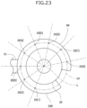
- Fig. 22 and Fig. 23 illustrate a valve body assembly 5B according to a first modification.
- the valve body assembly 5B has the same configuration as that of the valve body assembly 5A except that the valve body assembly 5B includes, instead of the mounting plate 23A, a mounting plate 23B with multiple holes 25.
- “same configuration” includes the meanings of "same configuration” and “substantially same configuration”.
- the mounting plate 23B has a circular arc shape.
- the central angle of the circular arc shape of the mounting plate 23B is approximately 320 degrees.
- the inner edge of the mounting plate 23B is integrally connected to the outer peripheral edge of a connection member 13.
- the connection member 13 and the mounting plate 23B constitute a single component.
- An axis L passes through the center of the circular arc shape of the mounting plate 23B and the center of the connection member 13.
- the mounting plate 23B protrudes radially outward from the connection member 13.
- the mounting plate 23B has the multiple holes 25.
- the holes 25 have a circular shape and extend through the mounting plate 23B. Each of the holes 25 is a receiving portion.
- the mounting plate 23B has 8 holes 25 (holes 25[1] to 25[8]).
- the holes 25[1] to 25[8] are on a circle Q1.
- a projecting portion 81 can be aligned with any one of the holes 25[1] to 25[8].
- the holes 25[1] to 25[8] correspond to multiple stator unit mounting positions.
- An angle around the axis L between the stator unit 7 with the projecting portion 81 aligned with the hole 25[j] and the stator unit 7 with the projecting portion 81 aligned with the hole 25[j + 1] is the angle d ⁇ [j].
- the angle d ⁇ [j] around the axis L between any two holes 25 adjacent to each other is 33.75 degrees. It is sufficient that the angle d ⁇ [j] be a multiple of the step angle ⁇ and satisfy the expression (1). Respective angles d ⁇ [j] may be different from each other.
- the step angle ⁇ of a stepping motor 66 is 3.75 degrees, the number M of excitation patterns is 8, and an integer N is 1.
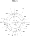
- Fig. 24 and Fig. 25 illustrate a valve body assembly 5C according to a second modification.
- the valve body assembly 5C has the same configuration as that of the valve body assembly 5A except that the valve body assembly 5C includes, instead of the mounting plate 23A, a mounting plate 23C with multiple holes 26.
- the mounting plate 23C has a circular arc shape.
- the central angle of the circular arc shape of the mounting plate 23C is approximately 320 degrees.
- the inner edge of the mounting plate 23C is integrally connected to the outer peripheral edge of a connection member 13.
- the connection member 13 and the mounting plate 23C constitute a single component.
- An axis L passes through the center of the circular arc shape of the mounting plate 23C and the center of the connection member 13.
- the mounting plate 23C protrudes radially outward from the connection member 13.
- the mounting plate 23C has multiple holes 26.
- the holes 26 have a circular shape and extend through the mounting plate 23C. Each of the holes 26 is a receiving portion.
- the mounting plate 23C has 8 holes 26 (holes 26[1] to 25[8]).
- the holes 26[1] to 25[8] are on a circle Q1.
- a projecting portion 81 can be aligned with any of the holes 26[1] to 26[8].
- An angle around the axis L between the stator unit 7 with the projecting portion 81 aligned with the hole 26[j] and the stator unit 7 with the projecting portion 81 aligned with the hole 26[j + 1] is the angle d ⁇ [j].
- the angle d ⁇ [j] around the axis L between any two sequentially numbered holes 26 is 93.75 degrees. It is sufficient that the angle d ⁇ [j] be a multiple of the step angle ⁇ and satisfy the expression (1). Respective angles d ⁇ [j] may be different from each other.
- the step angle ⁇ of a stepping motor 66 is 3.75 degrees, the number M of excitation patterns is 8, and an integer N is 3.
- the electric valve including the valve body assembly 5B or the valve body assembly 5C also has the same (including substantially the same) functions and effects as those of the electric valve 1 described above.
- the stator unit mounting position in which the stator unit 7 is mounted is changed, thereby enabling a valve opening pulse number C to vary.
- the valve opening pulse number C of the electric valve can be adjusted to a reference number Cs.
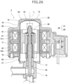
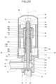
- Fig. 26 is a sectional view of the electric valve according to the second embodiment of the present invention.
- Fig. 27 is an enlarged sectional view of a part (mainly a lower end portion of a can and a mounting tab) of the electric valve in Fig. 26 .
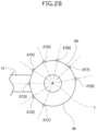
- Fig. 28 is a plan view of a valve body assembly of the electric valve in Fig. 26 .
- elements having the same configurations as those of the electric valve 1 are denoted by the same reference signs as those of the electric valve 1, and detailed descriptions of these elements are omitted.
- an electric valve 2 includes a valve body assembly 5D and a stator unit 7D.
- the valve body assembly 5D has the same configuration as that of the valve body assembly 5A described above except that (a) the valve body assembly 5D does not include the mounting plate 23A, and (b) a can 20 includes multiple projecting portions 27.
- the stator unit 7D has the same configuration as that of the stator unit 7 described above except that (c) the stator unit 7D includes a mounting tab 85 in an L-shape instead of the mounting tab 80 in the crank shape.
- the projecting portions 27 are disposed at the lower end portion of the can 20 and protrude radially outward. Each of the projecting portions 27 is a receiving portion.
- the can 20 has 8 projecting portions 27 (projecting portions 27[1] to 27[8]).
- the mounting tab 85 is a rectangular metal plate bent into the L-shape. A first end portion 85a of the mounting tab 85 is caulked to a conductive member 76. A second end portion 85b of the mounting tab 85 is disposed parallel to the can 20.
- the mounting tab 85 has a hole 86.
- the hole 86 is in the second end portion 85b of the mounting tab 85.
- the hole 86 has a circular shape and extends through the mounting tab 85.
- the hole 86 is a mounting portion.
- the hole 86 can be aligned with any one of the projecting portions 27[1] to 27[8] of the can 20. Specifically, when the stator unit 7D is rotated around an axis L clockwise in plan view, the tip ends of the projecting portions 27[1] to 27[8] fit into the hole 86 in order. When the tip end of one of the projecting portions 27[1] to 27[8] fits into the hole 86, the one of the projecting portions 27 is secured to the hole 86, and the stator unit 7D is positioned with respect to the valve body assembly 5D.
- the electric valve 2 includes multiple mounting positions in which the stator unit 7D is mounted on the valve body assembly 5D, and the mounting positions are referred to as "stator unit mounting positions". The stator unit mounting positions correspond to the projecting portions 27[1] to 27[8].
- An angle around the axis L between the stator unit 7D with the hole 86 aligned with the projecting portion 27[j] and the stator unit 7D with the hole 86 aligned with the projecting portion 27[j + 1] is the angle d ⁇ [j].
- the angle d ⁇ [j] around the axis L between any two projecting portions 27 adjacent to each other is 33.75 degrees. It is sufficient that the angle d ⁇ [j] be a multiple of the step angle ⁇ and satisfy the expression (1). Respective angles d ⁇ [j] may be different from each other.
- the electric valve 2 according to the second embodiment also has the same (including substantially the same) functions and effects as those of the electric valve 1 described above.
- the stator unit mounting position in which the stator unit 7D is mounted is changed, thereby enabling a valve opening pulse number C to vary.
- the valve opening pulse number C of the electric valve 2 can be adjusted to a reference number Cs.
- the electric valve 2 may include a valve body assembly 5E illustrated in Fig. 29 instead of the valve body assembly 5D.
- the valve body assembly 5E includes multiple recesses 28 at the lower end portion of the can 20.
- the recesses 28 correspond to multiple stator unit mounting positions.
- the electric valve 2 includes a stator unit (not illustrated) that includes a projecting portion that can be aligned with any one of the recesses 28.
- ⁇ represents a step angle of the stepping motor 66
- M represents a number of excitation patterns
- N represents an integer
- the angle ⁇ [k] of the k-th recess 28[k] around the axis L is represented by the following expression (2).
- ⁇ k M ⁇ N + 1 ⁇ k ⁇ 1 ⁇ ⁇
- the electric valve 2 may include a valve body assembly 5F illustrated in Fig. 30 instead of the valve body assembly 5D.
- the valve body assembly 5F includes multiple recesses 29 at the upper portion of the can 20.
- the recesses 29 correspond to multiple stator unit mounting positions.
- the electric valve 2 includes the stator unit (not illustrated) that includes a projecting portion that can be aligned with any one of the recesses 29.
- ⁇ represents the step angle of the stepping motor 66 and M represents the number of excitation patterns
- an angle ⁇ [k] of a k-th recess 29[k] around the axis L is represented by the expression (2).
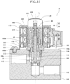
- Fig. 31 is a sectional view of the electric valve according to the third embodiment of the present invention.
- Fig. 32 is a plan view of a valve body of the electric valve in Fig. 31 .
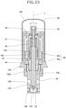
- Fig. 33 is a sectional view of a rotor unit of the electric valve in Fig. 31 .
- elements having the same configurations as those of the electric valve 1 are denoted by the same reference signs as those of the electric valve 1, and detailed descriptions of these elements are omitted.
- an electric valve 3 includes a valve body 110, a rotor unit 106, a stator unit 107, and a threaded member 191.
- the valve body 110 and the rotor unit 106 are members of a valve body assembly 105.
- the valve body 110 is made of a metal such as an aluminum alloy.
- the valve body 110 has a rectangular parallelepiped shape.
- the valve body 110 has a mounting hole 114.
- the mounting hole 114 is in an upper surface 110a of the valve body 110.
- the inner circumferential surface of the mounting hole 114 has an internal thread 114c.
- the valve body 110 includes a flow channel 115 and a flow channel 116.
- the flow channel 116 is connected to the flow channel 115 via the mounting hole 114.
- the valve body 110 has multiple internal thread holes 111.
- the multiple internal thread holes 111 are in the upper surface 110a of the valve body 110.
- the inner circumferential surface of each of the internal thread holes 111 has an internal thread.
- the valve body 110 has 8 internal thread holes 111 (internal thread holes 111[1] to 111[8]).
- the internal thread holes 111[1] to 111[8] are on a circle Q3.
- An axis L passes through the center of the circle Q3.
- the rotor unit 106 includes a can 20, a valve member 30, a driving section 40, a mounting member 150, and a valve seat member 155.
- the mounting member 150 has a circular cylindrical shape.
- the outer circumferential surface of the mounting member 150 has an external thread 150c.
- the external thread 150c is disposed on the lower part of the outer circumferential surface.
- the external thread 150c of the mounting member 150 is screwed into the internal thread 114c of the mounting hole 114 of the valve body 110.
- the mounting member 150 is mounted to the mounting hole 114 of the valve body 110 by a screw structure.
- the upper part of the mounting member 150 protrudes from the upper surface 110a of the valve body 110.
- the lower end portion of the can 20 is bonded to the upper part of the mounting member 150.
- the valve seat member 155 has a circular cylindrical shape.
- the valve seat member 155 includes a valve chamber 156.
- the valve seat member 155 includes a valve port 157 and a valve seat 158 that encloses the valve port 157.
- the valve seat member 155 is press-fitted downward into the mounting member 150 from the top.
- the upper part of the valve seat member 155 is held by the mounting member 150.
- a guide bush 43 is press-fitted into the upper part of the valve seat member 155.
- the lower part of the valve seat member 155 is disposed in the mounting hole 114 of the valve body 110.
- the valve seat member 155 has a lateral hole 159 that connects the valve chamber 156 and the mounting hole 114.
- the valve chamber 156 is connected to the flow channel 115 via the lateral hole 159 and the mounting hole 114.
- the valve chamber 156 is connected to the flow channel 116 via the valve port 157.
- a valve portion 33 of the valve member 30 is disposed in the valve port 157.
- a variable throttle is formed between the valve portion 33 and the valve port 157.
- the valve portion 33 faces the valve seat 158.
- the valve port 157 is closed when the valve portion 33 is in contact with the valve seat 158.
- the central axis of the mounting member 150 and the central axis of the valve seat member 155 are aligned with the axis L.
- the stator unit 107 includes a stator 60, a housing 170, and a mounting tab 180.
- the housing 170 is made of synthetic resin.
- the housing 170 is injection molded.
- the housing 170 houses the stator 60.
- the housing 170 includes a peripheral wall portion 171 in a circular cylindrical shape.
- the stator 60 is embedded in the peripheral wall portion 171.
- the mounting tab 180 is a rectangular metal plate bent into a crank shape.
- a first end portion 180a of the mounting tab 180 is caulked to a conductive member 176 embedded in the lower end portion of the peripheral wall portion 171.
- a second end portion 180b of the mounting tab 180 is parallel to the upper surface 110a of the valve body 110.
- the second end portion 180b is in contact with the upper surface 110a.
- the mounting tab 180 has a hole 181.
- the hole 181 is in the second end portion 180b.
- the hole 181 has a circular shape and extends through the mounting tab 180.
- the hole 181 may have a cut-out shape that communicates with the area around the mounting tab 180. Examples of a through hole include such a shape.
- the hole 181 can be aligned with any one of the internal thread holes 111[1] to 111[8] of the valve body 110. Specifically, when the stator unit 107 is rotated around the axis L clockwise in plan view, the position of the hole 181 matches with the positions of the internal thread holes 111[1] to 111[8] in order. When the threaded member 191 is disposed in the hole 181 and is screwed into any one of the internal thread holes 111[1] to 111[8], the mounting tab 180 is fixed to the valve body 110, and the stator unit 107 is positioned with respect to the valve body 110.
- the electric valve 3 includes multiple mounting positions in which the stator unit 107 is mounted on the valve body 110, the mounting positions are referred to as “stator unit mounting positions", and the stator unit mounting positions correspond to the internal thread holes 111 [1] to 111 [8] .
- An angle around the axis L between the stator unit 107 with the hole 181 aligned with the internal thread hole 111 [j] and the stator unit 107 with the hole 181 aligned with the internal thread hole 111[j + 1] is the angle d ⁇ [j].
- the angle d ⁇ [j] around the axis L between any two internal thread holes 111 adjacent to each other is 33.75 degrees. It is sufficient that the angle d ⁇ [j] be a multiple of the step angle ⁇ and satisfy the expression (1). Respective angles d ⁇ [j] may be different from each other.
- the electric valve 3 according to the third embodiment also has the same (including substantially the same) functions and effects as those of the electric valve 1 described above.
- the stator unit mounting position in which the stator unit 107 is mounted is changed, thereby enabling a valve opening pulse number C to vary.
- the valve opening pulse number C of the electric valve 3 can be adjusted to a reference number Cs.
- the electric valve 3 includes the threaded member 191 with an external thread.
- the valve body assembly 105 includes the multiple internal thread holes 111 corresponding to the stator unit mounting positions.
- the stator unit 107 includes the hole 181 that can be aligned with any one of the internal thread holes 111.
- the stator unit 107 is mounted on the valve body assembly 105 in one of the stator unit mounting positions corresponding to one of the internal thread holes 111 by the threaded member 191 being disposed in the hole 181 and screwed into the one of the internal thread holes 111.
- the stator unit 107 can be mounted on the valve body assembly 105.
- Fig. 34 is a sectional view of the electric valve according to the fourth embodiment of the present invention.
- Fig. 35 is a front view of the electric valve in Fig. 34 .
- Fig. 36 is a plan view of the electric valve in Fig. 34 .
- elements having the same configurations as those of the electric valves 1 and 3 are denoted by the same reference signs as those of the electric valves 1 and 3, and detailed descriptions of these elements are omitted.
- an electric valve 4 includes a valve body 110E, a rotor unit 106, a stator unit 107E, a spacer 187, and a threaded member 192.
- the valve body 110E, the rotor unit 106, and the spacer 187 are members of a valve body assembly 105E.
- the valve body 110E has the same configuration as that of the valve body 110 described above except that the valve body 110E includes, instead of the multiple internal thread holes 111, an internal thread hole 112 that is in a front surface 110b.
- the stator unit 107E has the same configuration as that of the stator unit 107 described above except that the stator unit 107E includes a mounting tab 185 in an L-shape instead of the mounting tab 180 in the crank shape.
- a first end portion 185a of the mounting tab 185 is caulked to a conductive member (not illustrated) embedded in the lower end portion of a peripheral wall portion 171.
- a second end portion 185b of the mounting tab 185 is parallel to the front surface 110b of the valve body 110E.
- the second end portion 185b is in contact with the front surface 110b.
- the mounting tab 185 has a hole 186.
- the hole 186 is in the second end portion 185b.
- the hole 186 is a long hole extending in an up-and-down direction in Fig. 35 .
- the hole 186 extends through the mounting tab 185.
- the mounting tab 185 is fixed to the valve body 110E by the threaded member 192 being disposed in the hole 186 and screwed into the internal thread hole 112 of the valve body 110E, and the stator unit is positioned with respect to the valve body 110E.
- the electric valve 4 includes a mounting position in which the stator unit 107E is mounted on the valve body 110E.
- the spacer 187 has a circular annular plate-like shape.
- a mounting member 150 of the rotor unit 106 is disposed in the spacer 187 and is screwed into a mounting hole 114 of the valve body 110E.
- the spacer 187 is located between the valve body 110E and the mounting member 150.
- one to eight spacers 187 can be located between the valve body 110E and the mounting member 150.
- a rotational angle of the mounting member 150 corresponding to the thickness per spacer 187 when the mounting member 150 is screwed into the mounting hole 114 is a step angle ⁇ .
- An angle of the rotor unit 106 around an axis L with respect to the valve body 110E corresponds to the number of spacers 187 located between the valve body 110E and the mounting member 150.
- the electric valve 4 includes multiple mounting positions in which the rotor unit 106 is mounted on the valve body 110E, and the mounting positions are referred to as "rotor unit mounting positions".
- the rotor unit mounting positions correspond to the number of the spacers 187.
- the number of the spacer 187 represents the sequential number of the rotor unit mounting positions.
- the rotor unit 106 can be mounted in any one of the rotor unit mounting positions.
- the angle d ⁇ [j] around the axis L between two rotor units 106 hypothetically mounted in any two sequentially numbered rotor unit mounting positions is 3.75 degrees. It is sufficient that the angle d ⁇ [j] be a multiple of the step angle ⁇ and satisfy the following expression (3). Respective angles d ⁇ [j] may be different from each other.
- M is the number of excitation patterns.
- U is any integer. d ⁇ j ⁇ M ⁇ ⁇ ⁇ U
- the angle ⁇ of the rotor unit mounting position around the axis L when k spacer(s) are located is represented by the following expression (4A).
- the step angle ⁇ of a stepping motor 66 is 3.75 degrees
- the number M of excitation patterns is 8, and the integer N is 0.
- the electric valve 4 includes the valve body 110E, the rotor unit 106 mounted on the valve body 110E, and the stator unit 107E mounted on the valve body 110E.
- the rotor unit 106 includes a valve seat member 155 that includes a valve seat 158, a rotor 41 that is rotatable with respect to the valve seat member 155, a valve member 30 that faces the valve seat 158 and moves toward the valve seat 158 when the rotor 41 rotates in the first direction, and a stopper mechanism 49 that restricts the rotation of the rotor 41 in the first direction when the rotor 41 is at a reference position Rx.
- the stator unit 107E includes a stator 60 that is disposed coaxially with the rotor 41 and constitutes the stepping motor 66 together with the rotor 41.
- the electric valve 4 includes the mounting position in which the stator unit 107E is mounted on the valve body 110E.
- the electric valve 4 includes the mounting positions in which the rotor unit 106 is mounted on the valve body 110E, the mounting positions being referred to as "rotor unit mounting positions".
- ⁇ represents the step angle of the stepping motor 66
- M represents the number of excitation patterns of the stepping motor 66
- K represents the number of the rotor unit mounting positions
- the angle d ⁇ around the axis L between one rotor unit mounting position and another rotor unit mounting position adjacent to the one rotor unit mounting position can be prevented from being a multiple of a number that is the number M of the excitation patterns multiplied by the step angle ⁇ . Therefore, the rotor unit 106 is mounted on the valve body 110E in another rotor unit mounting position instead of the one rotor unit mounting position, thereby enabling the position of the rotor 41 when pulse P corresponding to the specific excitation pattern is input to the stepping motor to be changed by a multiple of the step angle ⁇ .
- the step angle ⁇ corresponds to one pulse P to be input to the stepping motor 66.
- valve opening pulse number C is greater or less than a reference number Cs in the electric valve 4
- the rotor unit 106 is mounted in another rotor unit mounting position instead of the one rotor unit mounting position. This enables the valve opening pulse number C to be adjusted. Accordingly, it is possible to decrease the variation in the valve opening pulse number C among electric valves 4.
- the valve body 110E includes the mounting hole 114 with an internal thread 114c, and the internal thread 114c is disposed on the inner circumferential surface of the mounting hole 114.
- the rotor unit 106 includes the mounting member 150 with an external thread 150c, and the external thread 150c is disposed on the outer circumferential surface of the mounting member 150 and screwed into the internal thread 114c.
- the mounting member 150 holds the valve seat member 155.
- the mounting member 150 is disposed coaxially with the rotor 41. Eight spacers 187 can be located between the valve body 110E and the mounting member 150, and at least one spacer 187 is located between the valve body 110E and the mounting member 150.
- the rotational angle of the mounting member 150 around the axis L corresponding to the thickness per spacer 187 when the external thread 150c is screwed into the internal thread 114c is the step angle ⁇ . Therefore, the number of the spacer(s) 187 is changed and the rotor unit mounting position in which the rotor unit is mounted is changed, thereby enabling the valve opening pulse number C to vary. As a result, the valve opening pulse number C of the electric valve 4 can be adjusted to a reference number Cs.
- Fig. 37 is a sectional view of an electric valve according to a fifth embodiment of the present invention.
- Fig. 38 is a plan view of a valve body of the electric valve in Fig. 37 .
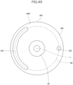
- Fig. 39 is a sectional view of a rotor unit of the electric valve in Fig. 37 .
- Fig. 40 is a plan view of the rotor unit in Fig. 39 .
- Fig. 41 is a plan view of the electric valve in Fig. 37 .
- elements having the same configurations as those of the electric valves 1, 3, and 4 are denoted by the same reference signs as those of the electric valves 1, 3, and 4, and detailed descriptions of these elements are omitted.
- the valve body 110F has the multiple internal thread holes 113.
- the multiple internal thread holes 113 are in an upper surface 110a of the valve body 110F.
- the inner circumferential surface of each internal thread hole 113 has an internal thread.
- the valve body 110F has 8 internal thread holes 113 (internal thread holes 113[1] to 113[8]).
- the internal thread holes 113[1] to 113[8] are on a circle Q5.
- An axis L passes through the center of the circle Q5.
- the valve body 110F has the internal thread hole 112.
- the internal thread hole 112 is in a front surface 110b of the valve body 110F.
- the stator unit 107E includes a mounting tab 185.
- the mounting tab 185 is fixed to the valve body 110F by the threaded member 192 being disposed in a hole 186 in a second end portion of the mounting tab 185 and screwed into the internal thread hole 112 of the valve body 110F, and the stator unit 107E is positioned with respect to the valve body 110F.
- the electric valve 5 includes a mounting position in which the stator unit 107E is mounted on the valve body 110F.
- the rotor unit 106F has the same configuration as that of the rotor unit 106 described above except that the rotor unit 106F includes a mounting member 250 and a valve seat member 255 instead of the mounting member 150 and the valve seat member 155.
- the valve seat member 255 has a circular cylindrical shape.
- the valve seat member 255 includes a valve chamber 256.
- the valve seat member 255 includes a valve port 257 and a valve seat 258 that encloses the valve port 257.
- the valve seat member 255 is press-fitted upward into the mounting member 250 from the bottom.
- the upper part of the valve seat member 255 is held by the mounting member 250.
- a guide bush 43 is press-fitted into the upper part of the valve seat member 255.
- the lower part of the valve seat member 255 is disposed in the mounting hole 114F of the valve body 110F.
- the valve seat member 255 has a lateral hole 259 that connects the valve chamber 256 and the mounting hole 114F.
- the valve chamber 256 is connected to a flow channel 115 via the lateral hole 259 and the mounting hole 114F.
- the valve chamber 256 is connected to a flow channel 116 via the valve port 257.
- a valve portion 33 of a valve member 30 is disposed in the valve port 257.
- a variable throttle is formed between the valve portion 33 and the valve port 257.
- the valve portion 33 faces the valve seat 258.
- the valve port 257 is closed when the valve portion 33 is in contact with the valve seat 258.
- the central axis of the mounting member 250 and the central axis of the valve seat member 255 are aligned with the axis L.
- the hole 253 of the disc portion 252 can be disposed in any of the internal thread holes 113[1] to 113[8] of the valve body 110F. Specifically, when the rotor unit 106F is rotated around the axis L clockwise in plan view, the position of the hole 253 matches with the positions of the internal thread holes 113[1] to 113[8] in order. When the threaded member 193 is disposed in the hole 253 and is screwed into any one of the internal thread holes 113[1] to 113[8], the disc portion 252 is fixed to the valve body 110F.
- the electric valve 5 includes multiple mounting positions in which the rotor unit 106F is mounted on the valve body 110F, the mounting positions are referred to as "rotor unit mounting positions", and the rotor unit mounting positions correspond to the internal thread holes 113[1] to 113[8].
- An angle around the axis L between the rotor unit 106F with the hole 253 aligned with the internal thread hole 113[j] and the rotor unit 106F with the hole 253 aligned with the internal thread hole 113[j + 1] is the angle d ⁇ [j].
- the angle d ⁇ [j] around the axis L between any two internal thread holes 113 adjacent to each other is 33.75 degrees. It is sufficient that the angle d ⁇ [j] be a multiple of the step angle ⁇ and satisfy the expression (3). Respective angles d ⁇ [j] may be different from each other.
- the step angle ⁇ of a stepping motor 66 is 3.75 degrees, the number M of excitation patterns is 8, and the integer N is 1.
- the electric valve 5 according to the fifth embodiment also has the same (including substantially the same) functions and effects as those of the electric valve 4 described above.
- the rotor unit mounting position in which the rotor unit 106F is mounted is changed, thereby enabling a valve opening pulse number C to vary.
- the valve opening pulse number C of the electric valve 5 can be adjusted to a reference number Cs.
- the electric valve 5 includes the threaded member 193 with an external thread.
- the valve body 110F includes the multiple internal thread holes 113 corresponding to the rotor unit mounting positions.
- the rotor unit 106F includes the hole 253 that can be aligned with any one of the internal thread holes 113.
- the rotor unit 106F is mounted on the valve body 110F in one of the rotor unit mounting positions corresponding to one of the internal thread holes 113 by the threaded member 193 being disposed in the hole 253 and screwed into the one of the internal thread holes 113.
- the rotor unit 106F can be mounted on the valve body 110F.
- the electric valve 5 may have a configuration in which the rotor unit 106F includes multiple through holes corresponding to the rotor unit mounting positions, the valve body 110F includes an internal thread hole that can be aligned with any one of the through holes, and the rotor unit is mounted on the valve body 110F in one of the rotor unit mounting positions corresponding to one of the through holes by the threaded member 193 being disposed in the one of the through holes and screwed into the internal thread hole.
- the mounting tab 80 is electrically connected to the yoke of the B-phase stator 62 via the conductive member 76.
- the mounting tab 80 may be directly connected to the yoke of the B-phase stator 62.
- the mounting tab 80 may, for example, be welded to or be in contact with the yoke of the B-phase stator 62.
- the mounting tab 80 may be integrally formed with the yoke of the B-phase stator 62 when the yoke is formed by press work.
- the mounting tab 80 or the conductive member 76 to which the mounting tab 80 is bonded may be fixed only to the housing 70.
- the mounting tab 85, the mounting tab 180, and the mounting tab 185 of the second embodiment to the fifth embodiment are also the same as or similar to the mounting tab 80.
- a circular cylindrical member includes a circular cylindrical member and a substantially circular cylindrical member.
Landscapes
- Engineering & Computer Science (AREA)
- General Engineering & Computer Science (AREA)
- Power Engineering (AREA)
- Mechanical Engineering (AREA)
- Physics & Mathematics (AREA)
- Thermal Sciences (AREA)
- Electrically Driven Valve-Operating Means (AREA)
Abstract

Description
- The present invention relates to an electric valve.
-
Patent Literature 1 discloses an example of an electric valve according to the related art. The electric valve is installed in a refrigeration cycle system of an air conditioner. The electric valve includes a valve body, a valve member, and a stepping motor for moving the valve member. The stepping motor includes a rotor and a stator. The rotor rotates in response to pulses input to the stepping motor. The valve member moves along with the rotation of the rotor, and the movement of the valve member changes an opening degree of a valve port of the valve body. When the rotor is at a reference position, a movable stopper fixed to the rotor is in contact with a fixed stopper fixed to the valve body, thereby restricting the rotation of the rotor in a first direction. Pulses to be input to the stepping motor correspond to states (excitation patterns) of drive currents to be supplied to the stator. The number of the excitation patterns is defined according to a configuration of the stepping motor. Pulses corresponding to the excitation patterns are input to the stepping motor sequentially and cyclically. - The electric valve is controlled by an electric valve control device. The electric valve control device, in an initialization operation, inputs pulses to the stepping motor to rotate the rotor in the first direction and positions the rotor at the reference position. Then, the electric valve control device inputs a predetermined number of pulses to the stepping motor to rotate the rotor in a second direction and positions the rotor at a valve opening position. The electric valve control device inputs pulses to the stepping motor starting from a pulse corresponding to a specific excitation pattern when positioning the rotor from the reference position to the valve opening position. When the rotor is positioned at the valve opening position, the valve port has the opening degree of a predetermined value.
- Patent Literature 1:
Japanese Unexamined Patent Application Publication No. 2020-16247 - In manufacturing the electric valve, the valve body assembly including the valve body and the rotor is manufactured separately from the stator unit including the stator. Then, the stator unit is assembled with the valve body assembly. Electric valves are manufactured such that each of the electric valves has the same number of pulses (a valve opening pulse number) required to rotate the rotor from the reference position to the valve opening position. However, depending on accuracy of components or accuracy of assembling components, the stator may deviate from its correct position around an axis with respect to the valve body assembly when the stator unit is mounted on the valve body. This causes the rotor to deviate from its correct position around the axis when the electric valve control device inputs pulses starting from the pulse corresponding to the specific excitation pattern and positions the rotor from the reference position to the valve opening position. As a result, there may be a variation in the valve opening pulse number among the electric valves.
- Accordingly, it is an object of the present invention to provide an electric valve capable of decreasing the variation in the valve opening pulse number.
- To achieve the object described above, an electric valve according to an aspect of the present invention includes a valve body assembly and a stator unit that is mounted on the valve body assembly. The valve body assembly includes a valve body that includes a valve seat, a rotor that is rotatable with respect to the valve body, a valve member that faces the valve seat and moves toward the valve seat when the rotor rotates in a first direction, and a stopper mechanism that restricts rotation of the rotor in the first direction when the rotor is at a reference position. The stator unit includes a stator that is disposed coaxially with the rotor and constitutes a stepping motor together with the rotor. The electric valve includes mounting positions in which the stator unit is mounted on the valve body assembly, and the mounting positions are referred to as stator unit mounting positions. Where θ represents a step angle of the stepping motor, M represents a number of excitation patterns of the stepping motor, K represents a number of the stator unit mounting positions, and U represents any integer, an angle dα[j] (j = 1, 2, ..., K - 1) around an axis between a j-th stator unit mounting position of the stator unit mounting positions and a (j + 1)-th stator unit mounting position of the stator unit mounting positions is a multiple of the step angle θ, and the following expression (1) is satisfied.

- In the present invention, preferably, an angle α[k] (k = 1, 2, ..., K) of a k-th stator unit mounting position of the stator unit mounting positions around the axis is represented by the following expression (2)

- In the present invention, preferably, the valve body assembly includes receiving portions corresponding to the stator unit mounting positions. Preferably, the stator unit includes a mounting portion capable of being aligned with any one of the receiving portions. Preferably, the mounting portion is a projection and the receiving portions are recesses or holes, or the mounting portion is a recess or a hole and the receiving portions are projections. Preferably, the stator unit is mounted in one of the stator unit mounting positions corresponding to one of the receiving portions by the mounting portion being secured to the one of the receiving portions.
- In the present invention, preferably, the electric valve includes a threaded member with an external thread. Preferably, the valve body assembly includes internal thread holes corresponding to the stator unit mounting positions. Preferably, the stator unit includes a through hole capable of being aligned with any one of the internal thread holes. Preferably, the stator unit is mounted in one of the stator unit mounting positions corresponding to one of the internal thread holes by the threaded member being disposed in the through hole and screwed into the one of the internal thread holes.
- To achieve the object described above, an electric valve according to another aspect of the present invention includes a valve body, a rotor unit that is mounted on the valve body, and a stator unit that is mounted on the valve body. The rotor unit includes a valve seat member that includes a valve seat, a rotor that is rotatable with respect to the valve seat member, a valve member that faces the valve seat and moves toward the valve seat when the rotor rotates in a first direction, and a stopper mechanism that restricts rotation of the rotor in the first direction when the rotor is at a reference position. The stator unit includes a stator that is disposed coaxially with the rotor and constitutes a stepping motor together with the rotor. The electric valve includes a mounting position in which the stator unit is mounted on the valve body. The electric valve includes mounting positions in which the rotor unit is mounted on the valve body, and the mounting positions are referred to as rotor unit mounting positions. Where θ represents a step angle of the stepping motor, M represents a number of excitation patterns of the stepping motor, K represents a number of the rotor unit mounting positions, and U represents any integer, an angle dβ[j] (j = 1, 2, ..., K - 1) around an axis between a j-th rotor unit mounting position of the rotor unit mounting positions and a (j + 1)-th rotor unit mounting position of the rotor unit mounting positions is a multiple of the step angle θ, and the following expression (3) is satisfied.

- In the present invention, preferably, an angle β[k] (k = 1, 2, ..., K) of a k-th rotor unit mounting position of the rotor unit mounting positions around the axis is represented by the following expression (4)

- In the present invention, preferably, the valve body includes a mounting hole with an internal thread, and the internal thread is disposed on an inner circumferential surface of the mounting hole. Preferably, the rotor unit includes a mounting member with an external thread, the external thread is disposed on an outer circumferential surface of the mounting member and screwed into the internal thread, and the mounting member holds the valve seat member. Preferably, the mounting member is disposed coaxially with the rotor. Preferably, where K represents the number of the rotor unit mounting positions, up to K spacers are located between the valve body and the mounting member, and at least one spacer is located between the valve body and the mounting member. Preferably, the step angle is equal to a rotational angle of the mounting member around the axis corresponding to a thickness per spacer when the external thread is screwed into the internal thread.
- In the present invention, preferably, the electric valve includes a threaded member with an external thread. Preferably, the valve body includes internal thread holes corresponding to the rotor unit mounting positions. Preferably, the rotor unit includes a through hole capable of being aligned with any one of the internal thread holes. Preferably, the rotor unit is mounted in one of the rotor unit mounting positions corresponding to one of the internal thread holes by the threaded member being disposed in the through hole and screwed into the one of the internal thread holes.
- In the present invention, preferably, the electric valve includes a threaded member with an external thread. Preferably, the rotor unit includes through holes corresponding to the rotor unit mounting positions. Preferably, the valve body includes an internal thread hole capable of being aligned with any one of the through holes. Preferably, the rotor unit is mounted in one of the rotor unit mounting positions corresponding to one of the through holes by the threaded member being disposed in the one of the through holes and screwed into the internal thread hole. Advantageous Effects of Invention
- According to the present invention, the electric valve includes the valve body assembly and the stator unit that is mounted on the valve body assembly. The electric valve includes the mounting positions in which the stator unit is mounted on the valve body assembly, and the mounting positions are referred to as "stator unit mounting positions". Where θ represents the step angle of the stepping motor, M represents the number of excitation patterns of the stepping motor, K represents the number of the stator unit mounting positions, and U represents any integer, the angle dα[j] (j = 1, 2, ..., K - 1) around the axis between the j-th stator unit mounting position and the (j + 1)-th stator unit mounting position is the multiple of the step angle θ, and the expression (1) is satisfied.
- With this configuration, an angle dα between one stator unit mounting position and another stator unit mounting position next to the one stator unit mounting position around the axis can be prevented from being a multiple of a number that is the number M of the excitation patterns multiplied by the step angle θ. Therefore, the stator unit is mounted on the valve body assembly in another stator unit mounting position instead of the one stator unit mounting position, thereby enabling the position of the rotor when the pulse corresponding to the specific excitation pattern is input to the stepping motor to be changed by a multiple of the step angle θ. The step angle θ corresponds to one pulse to be input to the stepping motor. As a result, in the electric valve, when the number of pulses (valve opening pulse number) required for the rotor to rotate from the reference position to the valve opening position is greater or less than a reference number of the valve opening pulse number, the stator unit is mounted in another stator unit mounting position instead of the one stator unit mounting position. This enables the valve opening pulse number to be adjusted. Accordingly, it is possible to decrease a variation in the valve opening pulse number among electric valves.
- Alternatively, according to the present invention, the electric valve includes the valve body, the rotor unit that is mounted on the valve body, and the stator unit that is mounted on the valve body. The electric valve includes the mounting position in which the stator unit is mounted on the valve body. The electric valve includes the multiple mounting positions in which the rotor unit is mounted on the valve body, and the mounting positions are referred to as "rotor unit mounting positions". Where θ represents the step angle of the stepping motor, M represents the number of excitation patterns of the stepping motor, K represents the number of the rotor unit mounting positions, and U represents any integer, the angle dβ[j] (j = 1, 2, ..., K - 1) around the axis between the j-th rotor unit mounting position and the (j + 1)-th rotor unit mounting position is the multiple of the step angle θ, and is represented by the expression (3).
- With this configuration, an angle dβ between one rotor unit mounting position and another rotor unit mounting position next to the one rotor unit mounting position around the axis can be prevented from being a multiple of a number that is the number M of excitation patterns multiplied by the step angle θ. Therefore, the rotor unit is mounted on the valve body in another rotor unit mounting position instead of the one rotor unit mounting position, thereby enabling the position of the rotor when the pulse corresponding to the specific excitation pattern is input to the stepping motor to be changed by a multiple of the step angle θ. The step angle θ corresponds to one pulse to be input to the stepping motor. As a result, in the electric valve, when the number of pulses (valve opening pulse number) required for the rotor to rotate from the reference position to the valve opening position is greater or less than the reference number of the valve opening pulse number, the rotor unit is mounted in another rotor unit mounting position instead of the one rotor unit mounting position. This enables the valve opening pulse number to be adjusted. Accordingly, it is possible to decrease a variation in the valve opening pulse number among electric valves.
-
- [
Fig. 1] Fig. 1 is a sectional view of an electric valve according to a first embodiment of the present invention. - [
Fig. 2] Fig. 2 is an enlarged sectional view of a part of the electric valve inFig. 1 . - [
Fig. 3] Fig. 3 is a sectional view of a valve body assembly of the electric valve inFig. 1 . - [
Fig. 4] Fig. 4 is a diagram of the valve body assembly inFig. 3 . - [
Fig. 5] Fig. 5 is a diagram of a valve stem holder of the valve body assembly inFig. 3 . - [
Fig. 6] Fig. 6 is a side view of a guide bush of the valve body assembly inFig. 3 . - [
Fig. 7] Fig. 7 is a diagram of a stopper member of the valve body assembly inFig. 3 . - [
Fig. 8] Fig. 8 is a plan view of the valve stem holder, the stopper member, a rotor, and a stator of the electric valve inFig. 1 . - [
Fig. 9] Fig. 9 is a diagram illustrating a stepping motor of the electric valve inFig. 1 . - [
Fig. 10] Fig. 10 is a diagram schematically illustrating the positional relationship between magnetic poles of the rotor and pole teeth of the stator (a configuration in which a valve opening pulse number is a reference number). - [
Fig. 11] Fig. 11 is a diagram schematically illustrating the positional relationship between the magnetic poles of the rotor and the pole teeth of the stator (a state in which pulse P1 is input). - [
Fig. 12] Fig. 12 is a diagram schematically illustrating the positional relationship between the magnetic poles of the rotor and the pole teeth of the stator (a state in which pulse P2 is input). - [
Fig. 13] Fig. 13 is a diagram schematically illustrating the positional relationship between the magnetic poles of the rotor and the pole teeth of the stator (a state in which pulse P3 is input). - [
Fig. 14] Fig. 14 is a diagram schematically illustrating the positional relationship between the magnetic poles of the rotor and the pole teeth of the stator (a configuration in which the valve opening pulse number is more than the reference number by 1). - [
Fig. 15] Fig. 15 is a diagram schematically illustrating the positional relationship between the magnetic poles of the rotor and the pole teeth of the stator (a state in which pulse P1 is input). - [
Fig. 16] Fig. 16 is a diagram schematically illustrating the positional relationship between the magnetic poles of the rotor and the pole teeth of the stator (a state in which pulse P2 is input). - [
Fig. 17] Fig. 17 is a diagram schematically illustrating the positional relationship between the magnetic poles of the rotor and the pole teeth of the stator (a state in which pulse P3 is input). - [
Fig. 18] Fig. 18 is a diagram schematically illustrating the positional relationship between the magnetic poles of the rotor and the pole teeth of the stator (a configuration in which the valve opening pulse number is less than the reference number by 1). - [
Fig. 19] Fig. 19 is a diagram schematically illustrating the positional relationship between the magnetic poles of the rotor and the pole teeth of the stator (a state in which pulse P1 is input). - [
Fig. 20] Fig. 20 is a diagram schematically illustrating the positional relationship between the magnetic poles of the rotor and the pole teeth of the stator (a state in which pulse P2 is input). - [
Fig. 21] Fig. 21 is a diagram schematically illustrating the positional relationship between the magnetic poles of the rotor and the pole teeth of the stator (a state in which pulse P3 is input). - [
Fig. 22] Fig. 22 is a sectional view of a first modification of the valve body assembly inFig. 3 . - [
Fig. 23] Fig. 23 is a plan view of the valve body assembly inFig. 22 . - [
Fig. 24] Fig. 24 is a sectional view of a second modification of the valve body assembly inFig. 3 . - [
Fig. 25] Fig. 25 is a plan view of the valve body assembly inFig. 24 . - [
Fig. 26] Fig. 26 is a sectional view of an electric valve according to a second embodiment of the present invention. - [
Fig. 27] Fig. 27 is an enlarged sectional view of a part of the electric valve inFig. 26 . - [
Fig. 28] Fig. 28 is a plan view of a valve body assembly of the electric valve inFig. 26 . - [
Fig. 29] Fig. 29 is a sectional view of a first modification of the valve body assembly inFig. 28 . - [
Fig. 30] Fig. 30 is a sectional view of a second modification of the valve body assembly inFig. 28 . - [
Fig. 31] Fig. 31 is a sectional view of an electric valve according to a third embodiment of the present invention. - [
Fig. 32] Fig. 32 is a plan view of a valve body of the electric valve inFig. 31 . - [
Fig. 33] Fig. 33 is a sectional view of a rotor unit of the electric valve inFig. 31 . - [
Fig. 34] Fig. 34 is a sectional view of an electric valve according to a fourth embodiment of the present invention. - [
Fig. 35] Fig. 35 is a front view of the electric valve inFig. 34 . - [
Fig. 36] Fig. 36 is a plan view of the electric valve inFig. 34 . - [
Fig. 37] Fig. 37 is a sectional view of an electric valve according to a fifth embodiment of the present invention. - [
Fig. 38] Fig. 38 is a plan view of a valve body of the electric valve inFig. 37 . - [
Fig. 39] Fig. 39 is a sectional view of a rotor unit of the electric valve inFig. 37 . - [
Fig. 40] Fig. 40 is a plan view of the rotor unit inFig. 39 . - [
Fig. 41] Fig. 41 is a plan view of the electric valve inFig. 37 . - An electric valve according to a first embodiment of the present invention is described below with reference to
Fig. 1 to Fig. 21 . The electric valve according to the present embodiment is used as, for example, a flow control valve for controlling the flow rate of refrigerant in a refrigeration cycle system of an air conditioner. -
Fig. 1 is a sectional view of the electric valve according to the first embodiment of the present invention.Fig. 2 is an enlarged sectional view of a part (mainly a mounting plate and a mounting tab) of the electric valve inFig. 1 .Fig. 3 is a sectional view of a valve body assembly of the electric valve inFig. 1 .Fig. 4 is a diagram of the valve body assembly inFig. 3 .Fig. 4A is a plan view of the valve body assembly.Fig. 4B is an enlarged plan view of a part (mainly the mounting plate) of the valve body assembly.Fig. 5 is a diagram of a valve stem holder of the valve body assembly inFig. 3 .Fig. 5A is a perspective view of the valve stem holder.Fig. 5B is a plan view of the valve stem holder.Fig. 6 is a side view of a guide bush of the valve body assembly inFig. 3 .Fig. 7 is a diagram of a stopper member of the valve body assembly inFig. 3 .Fig. 7A is a perspective view of the stopper member, andFig. 7B is a plan view of the stopper member.Fig. 8 is a plan view of the valve stem holder, the stopper member, a rotor, and a stator of the electric valve inFig. 1 .Fig. 8 schematically illustrates the stator.Fig. 8 schematically illustrates magnetic poles of the rotor.Fig. 9 is a diagram illustrating a stepping motor of the electric valve inFig. 1 .Fig. 9A schematically illustrates the rotor and coils of the stator.Fig. 9B illustrates an example of the correspondence between pulses and drive currents to be supplied to the stator.Fig. 10 to Fig. 21 are diagrams schematically illustrating the positional relationships between the magnetic poles of the rotor and pole teeth of the stator.Fig. 10 to Fig. 13 illustrate a configuration in which a valve opening pulse number is a reference number.Fig. 14 to Fig. 17 illustrate a configuration in which the valve opening pulse number is more than the reference number by 1.Fig. 18 to Fig. 21 illustrate a configuration in which the valve opening pulse number is less than the reference number by 1.Fig. 11 ,Fig. 15 , andFig. 19 illustrate states in which pulse P1 is input to the stepping motor.Fig. 12 ,Fig. 16 , andFig. 20 illustrate states in which pulse P2 is input to the stepping motor.Fig. 13 ,Fig. 17 , andFig. 21 illustrate states in which pulse P3 is input to the stepping motor.Fig. 10 to Fig. 21 schematically illustrate the stator.Fig. 10 to Fig. 21 schematically illustrate the magnetic poles of the rotor. - As illustrated in
Fig. 1 , anelectric valve 1 according to the first embodiment includes avalve body assembly 5A and astator unit 7. - As illustrated in
Fig. 3 , thevalve body assembly 5A includes avalve body 10, acan 20, a mountingplate 23A, avalve member 30, and adriving section 40. - The
valve body 10 includes abody member 11 and aconnection member 13. Thebody member 11 has a circular columnar shape. Thebody member 11 includes avalve chamber 14. Afirst conduit 15 and asecond conduit 16 are bonded to thebody member 11. Thefirst conduit 15 is disposed in a direction (lateral direction inFig. 3 ) perpendicular to an axis L and is connected to thevalve chamber 14. Thesecond conduit 16 is disposed in a direction of the axis L (up-and-down direction inFig. 3 ) and is connected to thevalve chamber 14 via avalve port 17. Thevalve port 17 is enclosed by avalve seat 18, which has a circular annular shape, in thevalve chamber 14. Thebody member 11 includes afitting hole 11a in a circular shape. Thefitting hole 11a is in the upper end surface of thebody member 11. The inner circumferential surface of thefitting hole 11a has aplanar surface 11d facing leftward inFig. 3 . Astem hole 11b is provided at the bottom of thefitting hole 11a and communicates with thevalve chamber 14. Theconnection member 13 has a circular annular plate-like shape. The inner circumferential edge of theconnection member 13 is bonded to the upper end portion of thebody member 11. Thebody member 11 and theconnection member 13 are made of a metal, such as an aluminum alloy, stainless steel, or brass. - The
can 20 is made of a metal, such as stainless steel. Thecan 20 has a circular cylindrical shape. Thecan 20 is open at the lower end portion and is closed at the upper end portion. The lower end portion of thecan 20 is bonded to the outer peripheral edge of theconnection member 13. - As illustrated in
Fig. 4 , the mountingplate 23A has a circular arc shape. The central angle of the circular arc shape of the mountingplate 23A is approximately 50 degrees. The inner edge of the mountingplate 23A is integrally connected to the outer peripheral edge of theconnection member 13. Theconnection member 13 and the mountingplate 23A constitute a single component. The axis L passes through the center of the circular arc shape of the mountingplate 23A and the center of theconnection member 13. The mountingplate 23A protrudes radially outward from theconnection member 13. The mountingplate 23A hasmultiple holes 24. Theholes 24 have a circular shape and extend through the mountingplate 23A. Each of theholes 24 is a receiving portion. In the present embodiment, the mountingplate 23A has 9 holes 24 (holes 24 [1] to 24[9]). The holes 24[1] to 24[9] are on a circle Q1. The axis L passes through the center of the circle Q1. - The
valve member 30 includes afirst stem portion 31, asecond stem portion 32, and avalve portion 33. Thefirst stem portion 31 has a circular columnar shape. Thesecond stem portion 32 has a circular columnar shape. The diameter of thesecond stem portion 32 is smaller than the diameter of thefirst stem portion 31. Thesecond stem portion 32 is provided coaxially and continuously with the upper end portion of thefirst stem portion 31. Thevalve member 30 has astep portion 34. Thestep portion 34 is a circular annular plane facing upward. Thestep portion 34 is disposed in the part in which thesecond stem portion 32 and thefirst stem portion 31 are continuous with each other. Thevalve portion 33 has a conical shape with a diameter decreasing from top to bottom. Thevalve portion 33 is provided coaxially and continuously with the lower end portion of thefirst stem portion 31. Thevalve portion 33 is disposed in thevalve port 17. A variable throttle is formed between thevalve portion 33 and thevalve port 17. Thevalve portion 33 faces thevalve seat 18. Thevalve port 17 is closed when thevalve portion 33 is in contact with thevalve seat 18. - The driving
section 40 moves thevalve member 30 in the direction of the axis L. The movement of thevalve member 30 opens and closes thevalve port 17. The drivingsection 40 includes arotor 41, avalve stem holder 42, aguide bush 43, astopper member 44, and a fixedmember 45. - The
rotor 41 has a circular cylindrical shape. The outer diameter of therotor 41 is slightly smaller than the inner diameter of thecan 20. Therotor 41 is disposed inside thecan 20. Therotor 41 is rotatable with respect to thevalve body 10. Therotor 41 has a plurality of north (N) poles and a plurality of south (S) poles. The N poles and the S poles are disposed on the outer circumferential surface of therotor 41. The N poles and the S poles extend in the direction of the axis L. The N poles and the S poles are alternately arranged at regular angular intervals in the circumferential direction. In the present embodiment, therotor 41 includes 12 N poles and 12 S poles. The angle between adjacent N and S poles is 15 degrees. -
Fig. 5 illustrates thevalve stem holder 42. Thevalve stem holder 42 has a circular cylindrical shape. Thevalve stem holder 42 is open at the lower end portion and is closed at the upper end portion. Thevalve stem holder 42 is fitted into afitting hole 41a of therotor 41. Thevalve stem holder 42 rotates together with therotor 41. Amovable stopper 42s is disposed at the lower end portion on the outer circumferential surface of thevalve stem holder 42. Themovable stopper 42s is a protrusion extending radially outward from the outer circumferential surface of thevalve stem holder 42. Thevalve stem holder 42 has astem hole 42b. Thestem hole 42b is in anupper wall portion 42a of thevalve stem holder 42. Thesecond stem portion 32 of thevalve member 30 is disposed in thestem hole 42b movably in the direction of the axis L. Awasher 46 is disposed on the lower surface of theupper wall portion 42a of thevalve stem holder 42. Avalve closing spring 47 is disposed between thestep portion 34 of thevalve member 30 and thewasher 46. Thevalve closing spring 47 is a coil spring and pushes thevalve member 30 toward thevalve seat 18. The inner circumferential surface of thevalve stem holder 42 has aninternal thread 42c. Themovable stopper 42s is fixed with respect to therotor 41. -
Fig. 6 illustrates theguide bush 43. Theguide bush 43 includes abase portion 43a and asupport portion 43b. Thebase portion 43a has a circular cylindrical shape. Thesupport portion 43b has a circular cylindrical shape. The outer circumferential surface of thebase portion 43a has aplanar surface 43d. Thebase portion 43a is press-fitted into thefitting hole 11a of thebody member 11, and theplanar surface 43d is in contact with theplanar surface 11d of thefitting hole 11a. Consequently, the central axis of thebody member 11 and the central axis of theguide bush 43 are aligned with the axis L, and theguide bush 43 is correctly positioned with respect to thebody member 11 around the axis L. The outer diameter of thesupport portion 43b is smaller than the outer diameter of thebase portion 43a. The inner diameter of thesupport portion 43b is equal to the inner diameter of thebase portion 43a. Thesupport portion 43b is provided coaxially and continuously with the upper end portion of thebase portion 43a. The outer circumferential surface of thesupport portion 43b has anexternal thread 43c. Theexternal thread 43c is screwed into theinternal thread 42c of thevalve stem holder 42. Thefirst stem portion 31 of thevalve member 30 is disposed inside theguide bush 43. Theguide bush 43 supports thevalve member 30 movably in the direction of the axis L. -
Fig. 7 illustrates thestopper member 44. Thestopper member 44 includes astopper body 44a. Thestopper body 44a has a circular cylindrical shape. The inner circumferential surface of thestopper body 44a has aninternal thread 44c. A fixedstopper 44s is disposed on the outer circumferential surface of thestopper body 44a. The fixedstopper 44s is a protrusion extending radially outward from the outer circumferential surface of thestopper body 44a. Theexternal thread 43c is screwed into theinternal thread 44c until thestopper body 44a comes into contact with thebase portion 43a of theguide bush 43. This enables thestopper member 44 to be fixed to theguide bush 43. The fixedstopper 44s is fixed with respect to thevalve body 10. - The fixed
member 45 includes a fixedportion 45a and aflange portion 45b. The fixedportion 45a has a stepped circular cylindrical shape. Thesecond stem portion 32 of thevalve member 30 is disposed inside the fixedportion 45a. The fixedportion 45a is bonded to thesecond stem portion 32. Theflange portion 45b is provided continuously with the lower end portion of the fixedportion 45a. Areturn spring 48 is disposed such that thereturn spring 48 encloses the fixedmember 45. Thereturn spring 48 is a coil spring. - The
stator unit 7 includes astator 60, ahousing 70, and a mountingtab 80. - The
stator 60 has a circular cylindrical shape. Thestator 60 includes anA-phase stator 61 and a B-phase stator 62. - The
A-phase stator 61 includes a plurality of claw-poletype pole teeth pole teeth 61a point down, and the tip ends of thepole teeth 61b point up. Thepole teeth 61a and thepole teeth 61b are alternately arranged at regular angular intervals in the circumferential direction. In the present embodiment, theA-phase stator 61 includes 12pole teeth 61a and 12pole teeth 61b. The angle betweenadjacent pole teeth coil 61c of theA-phase stator 61 is energized, thepole teeth 61a and thepole teeth 61b have mutually opposite polarities. - The B-
phase stator 62 includes a plurality of claw-poletype pole teeth pole teeth 62a point down, and the tip ends of thepole teeth 62b point up. Thepole teeth 62a and thepole teeth 62b are alternately arranged at regular angular intervals in the circumferential direction. In the present embodiment, the B-phase stator 62 includes 12pole teeth 62a and 12pole teeth 62b. The angle betweenadjacent pole teeth coil 62c of the B-phase stator 62 is energized, thepole teeth 62a and thepole teeth 62b have mutually opposite polarities. - The
A-phase stator 61 is coaxially disposed on the B-phase stator 62. When viewed in the direction of the axis L, the angle between each of thepole teeth 61a of theA-phase stator 61 and a corresponding adjacent one of thepole teeth 62a of the B-phase stator 62 is 7.5 degrees. In other words, the B-phase stator 62 is at a position rotated around the axis L by 7.5 degrees with respect to theA-phase stator 61 from a position where thepole teeth 61a are aligned with thepole teeth 62a in the direction of the axis L. As illustrated inFig. 9A , thecoil 61c of theA-phase stator 61 includes terminals A1 and A2. Thecoil 62c of the B-phase stator 62 includes terminals B1 and B2. The terminals A1 and A2 and the terminals B1 and B2 are electrically connected to a motor driver (not illustrated). - The
can 20 is disposed inside thestator 60. Therotor 41 is disposed inside thecan 20. Thestator 60 and therotor 41 are members of a steppingmotor 66. In the present embodiment, the excitation mode of the steppingmotor 66 is 1-2 phase excitation. The step angle θ of the steppingmotor 66 is 3.75 degrees. The step angle θ is a rotational angle per pulse in the steppingmotor 66. - The
rotor 41 is rotated by pulses P (P1 to P8) input to the steppingmotor 66. Specifically, therotor 41 is rotated by drive currents, corresponding to pulses P, supplied to thestator 60 of the steppingmotor 66. In this specification, the expression "pulses P are input to the steppingmotor 66" is synonymous with "drive currents corresponding to pulses P are supplied to thestator 60 of the steppingmotor 66".Fig. 9B illustrates an example of the correspondence between pulses P1 to P8 and states of drive currents to be supplied to the stator 60 (hereinafter referred to as "excitation patterns"). InFig. 9B , (+) indicates supply of the drive current flowing from the terminal A1 to the terminal A2 or supply of the drive current flowing from the terminal B1 to the terminal B2, (-) indicates supply of the drive current flowing from the terminal A2 to the terminal A1 or supply of the drive current flowing from the terminal B2 to the terminal B1, and (0) indicates that no drive current is supplied. In the present embodiment, the number M of excitation patterns is 8. Pulses P1 to P8 illustrated inFig. 9B are input to the steppingmotor 66 in order. - In response to pulse P1 being input, the drive current flowing from the terminal A1 to the terminal A2 is supplied to the
coil 61c (+), and no drive current is supplied to thecoil 62c (0). - In response to pulse P2 being input, the drive current flowing from the terminal A1 to the terminal A2 is supplied to the
coil 61c (+), and the drive current flowing from the terminal B2 to the terminal B1 is supplied to thecoil 62c (-). - In response to pulse P3 being input, no drive current is supplied to the
coil 61c (0), and the drive current flowing from the terminal B2 to the terminal B1 is supplied to thecoil 62c (-). - In response to pulse P4 being input, the drive current flowing from the terminal A2 to the terminal A1 is supplied to the
coil 61c (-), and the drive current flowing from the terminal B2 to the terminal B1 is supplied to thecoil 62c (-). - In response to pulse P5 being input, the drive current flowing from the terminal A2 to the terminal A1 is supplied to the
coil 61c (-), and no drive current is supplied to thecoil 62c (0). - In response to pulse P6 being input, the drive current flowing from the terminal A2 to the terminal A1 is supplied to the
coil 61c (-), and the drive current flowing from the terminal B1 to the terminal B2 is supplied to thecoil 62c (+). - In response to pulse P7 being input, no drive current is supplied to the
coil 61c (0), and the drive current flowing from the terminal B1 to the terminal B2 is supplied to thecoil 62c (+). - In response to pulse P8 being input, the drive current flowing from the terminal A1 to the terminal A2 is supplied to the
coil 61c (+), and the drive current flowing from the terminal B1 to the terminal B2 is supplied to thecoil 62c (+). - In rotating the
rotor 41 in a first direction (clockwise inFig. 8 ), pulses P are cyclically input to the steppingmotor 66 in descending order (in the order from pulse P8 to pulse P1). When therotor 41 rotates in the first direction, a screw-feed action between theinternal thread 42c of thevalve stem holder 42 and theexternal thread 43c of theguide bush 43 moves therotor 41 and thevalve stem holder 42 downward. The rotor 41 (the valve stem holder 42) pushes thevalve member 30 downward via thevalve closing spring 47. Thevalve member 30 moves downward, and thevalve portion 33 comes into contact with thevalve seat 18. At this time, therotor 41 is at a valve closing position Rc. When therotor 41 at this position further rotates in the first direction, thevalve closing spring 47 is compressed and therotor 41 and thevalve stem holder 42 further move downward. Thevalve member 30 does not move downward. When themovable stopper 42s of thevalve stem holder 42 comes into contact with the fixedstopper 44s of thestopper member 44, the rotation of therotor 41 in the first direction is restricted. At this time, therotor 41 is at a reference position Rx. Themovable stopper 42s and the fixedstopper 44s constitute astopper mechanism 49 that restricts the rotation of therotor 41 in the first direction. - In rotating the
rotor 41 in a second direction (counterclockwise inFig. 8 ) opposite to the first direction, pulses P are cyclically input to the steppingmotor 66 in ascending order (in the order from pulse P1 to pulse P8). When therotor 41 rotates in the second direction, the screw-feed action between theinternal thread 42c of thevalve stem holder 42 and theexternal thread 43c of theguide bush 43 moves therotor 41 and thevalve stem holder 42 upward. The rotor 41 (the valve stem holder 42) pushes the fixedmember 45 upward. Thevalve member 30 moves upward together with the fixedmember 45 and separates from thevalve seat 18. Therotor 41 is considered to be at a valve opening position Ro when a fluid flow rate at the valve port 17 (opening degree of the valve port 17) reaches a predetermined value in a predetermined flow-rate measuring environment. The predetermined value is set as appropriate according to the configuration and application of theelectric valve 1. - The
housing 70 is made of synthetic resin. Thehousing 70 is injection molded. Thehousing 70 houses thestator 60. Thehousing 70 includes aperipheral wall portion 71 and anupper wall portion 72. - The
peripheral wall portion 71 has a circular cylindrical shape. Thestator 60 is embedded in theperipheral wall portion 71. Theupper wall portion 72 is provided continuously with the upper end portion of theperipheral wall portion 71. The inner circumferential surface of theperipheral wall portion 71, the inner surface of theupper wall portion 72, and the inner circumferential surface of thestator 60 form aninner space 74 of thestator unit 7. Thecan 20 is disposed inside theinner space 74. - The mounting
tab 80 is a rectangular metal plate bent into a crank shape. Afirst end portion 80a of the mountingtab 80 is caulked to aconductive member 76 embedded in the lower end portion of theperipheral wall portion 71. The mountingtab 80 may be welded to theconductive member 76. Theconductive member 76 is electrically connected to a yoke of the B-phase stator 62. The mountingtab 80 has a projectingportion 81. The projectingportion 81 is disposed at asecond end portion 80b of the mountingtab 80. The projectingportion 81 projects upward. The projectingportion 81 is pressed to alower surface 23a of the mountingplate 23A. The projectingportion 81 is a mounting portion. - The projecting
portion 81 can be aligned with any one of the holes 24[1] to 24[9] of the mountingplate 23A. Specifically, when thestator unit 7 is rotated around the axis L clockwise in plan view, the tip end of the projectingportion 81 fits into the holes 24[1] to 24[9] in order. When the tip end of the projectingportion 81 fits into one of the holes 24[1] to 24[9], the projectingportion 81 is secured to the one of theholes 24, and thestator unit 7 is positioned with respect to thevalve body assembly 5A. Theelectric valve 1 includes multiple mounting positions in which thestator unit 7 is mounted on thevalve body assembly 5A, and the mounting positions are referred to as "stator unit mounting positions". The stator unit mounting positions correspond to the holes 24[1] to 24[9]. Thestator unit 7 can be mounted in any one of the stator unit mounting positions. - In the present embodiment,
- 1: when the angle α[1] of the hole 24[1] around the axis L is 0 degrees,
- 2: the angle α[2] of the hole 24[2] around the axis L is 3.75 degrees in the first direction,
- 3: the angle α[3] of the hole 24[3] around the axis L is 7.5 degrees in the first direction,
- 4: the angle α[4] of the hole 24[4] around the axis L is 11.25 degrees in the first direction,
- 5: the angle α[5] of the hole 24[5] around the axis L is 15 degrees in the first direction,
- 6: the angle α[6] of the hole 24[6] around the axis L is 18.75 degrees in the first direction,
- 7: the angle α[7] of the hole 24[7] around the axis L is 22.5 degrees in the first direction,
- 8: the angle α[8] of the hole 24[8] around the axis L is 26.25 degrees in the first direction, and
- 9: the angle α[9] of the hole 24[9] around the axis L is 30 degrees in the first direction.
- The angles of the holes 24[1] to 24[9] around the axis L increase by 3.75 degrees in the first direction.
- In the holes 24[1] to 24[9], an angle dα[j] (j = 1 to 8) around the axis L between a j-th hole 24[j] and a (j + 1)-th hole 24[j + 1] is 3.75 degrees. An angle around the axis L between the
stator unit 7 with the projectingportion 81 aligned with the hole 24[j] and thestator unit 7 with the projectingportion 81 aligned with the hole 24[j + 1] is the angle dα[j]. - In the present embodiment, the angle dα[j] around the axis L between any two
holes 24 adjacent to each other is 3.75 degrees. It is sufficient that the angle dα[j] be a multiple of the step angle θ and satisfy the following expression (1). Respective angles dα[j] may be different from each other. M is the number of excitation patterns. U is any integer.
- The angle α[k] (k = 1 to 9) of a k-th hole 24[k] around the axis L is represented by the following expression (2A). The step angle θ of the stepping
motor 66 is 3.75 degrees, the number of the excitation patterns M is 8, and the integer N is 0.
- In the
electric valve 1, the respective central axes of the valve body 10 (thebody member 11, the connection member 13), thevalve port 17, thecan 20, thevalve member 30, therotor 41, thevalve stem holder 42, theguide bush 43, and the stator 60 (theA-phase stator 61, the B-phase stator 62) are aligned with the axis L. The center of the circular arc shape of the mountingplate 23A is also aligned with the axis L. - Next, an example of an initialization operation of the
electric valve 1 and an example of an adjustment process of the stator unit mounting positions are described. - The
electric valve 1 is controlled by an electric valve control device (not illustrated). The electric valve control device inputs, in the initialization operation of theelectric valve 1, pulses P1 to P8 to the steppingmotor 66 in descending order to rotate the rotor in the first direction and positions therotor 41 at the reference position Rx. Then, the electric valve control device inputs pulses P1 to P8 to the steppingmotor 66 in ascending order to rotate therotor 41 in the second direction and positions therotor 41 at the valve opening position Ro. The electric valve control device inputs pulses P starting from pulse P1 in positioning therotor 41 at the valve opening position Ro. Pulse P1 is pulse P corresponding to the specific excitation pattern. The number of pulses required to rotate therotor 41 from the reference position Rx to the valve opening position Ro (a valve opening pulse number C) is a reference number Cs (for example, Cs = 50). -
Fig. 10 illustrates a configuration in which thestator unit 7 is mounted around the axis L in a correct position with respect to thevalve body assembly 5A when the projectingportion 81 of the mountingtab 80 is secured to the hole 24 [5] of the mountingplate 23A. In this configuration, the magnetic poles of therotor 41 radially face thepole teeth A-phase stator 61 when therotor 41 is at the reference position Rx. The positional relationship between therotor 41 and the stator 60 (A-phase stator 61, B-phase stator 62) is described by focusing on one magnetic pole (magnetic pole 41s) of therotor 41, one pole tooth (pole tooth 61s) of theA-phase stator 61, and one pole tooth (pole tooth 62s) of B-phase stator 62. Themagnetic pole 41s, thepole tooth 61s, and thepole tooth 62s are marked with a dot for easy understanding of the positional relationship. - In the configuration illustrated in
Fig. 10 , when pulse P1 is input to the steppingmotor 66, thepole tooth 61s attracts themagnetic pole 41s. Consequently, as illustrated inFig. 11 , themagnetic pole 41s radially faces thepole tooth 61s. At this time, themovable stopper 42s is in contact with the fixedstopper 44s, and therotor 41 is at the reference position Rx. Next, when pulse P2 is input to the steppingmotor 66, thepole tooth 61s and thepole tooth 62s attract themagnetic pole 41s. Consequently, as illustrated inFig. 12 , therotor 41 rotates by the step angle θ in the second direction from the reference position Rx where therotor 41 is located inFig. 11 . Next, when pulse P3 is input to the steppingmotor 66, thepole tooth 62s attracts themagnetic pole 41s. Consequently, as illustrated inFig. 13 , therotor 41 rotates by the step angle θ in the second direction from the position where the rotor is located inFig. 12 , and themagnetic pole 41s radially faces thepole tooth 62s. Thereafter, when pulses P are cyclically input in ascending order, therotor 41 rotates by the step angle θ in the second direction in response to pulse P being input. When the number of pulses P being input reaches the reference number Cs, therotor 41 is correctly positioned at the valve opening position Ro. -
Fig. 14 illustrates a configuration in which thestator unit 7 is mounted in a position where thestator unit 7 is rotated around the axis L by the step angle θ in the first direction from the correct position with respect to thevalve body assembly 5A when the projectingportion 81 of the mountingtab 80 is secured to the hole 24 [5] of the mountingplate 23A. In this configuration, when therotor 41 is at the reference position Rx, themagnetic pole 41s of therotor 41 is at a position where themagnetic pole 41s is rotated by the step angle θ in the second direction from a position where themagnetic pole 41s radially faces thepole tooth 61s of theA-phase stator 61. - In the configuration illustrated in
Fig. 14 , when pulse P1 is input to the steppingmotor 66, thepole tooth 61s attracts themagnetic pole 41s. However, themovable stopper 42s is in contact with the fixedstopper 44s, which restricts the rotation of therotor 41 in the first direction. Consequently, as illustrated inFig. 15 , themagnetic pole 41s does not radially face thepole tooth 61s, even though therotor 41 is positioned at the reference position Rx. Next, when pulse P2 is input to the steppingmotor 66, thepole tooth 61s and thepole tooth 62s attract themagnetic pole 41s. At this time, therotor 41 does not rotate, and therotor 41 is maintained at the reference position Rx as illustrated inFig. 16 . Next, when pulse P3 is input to the steppingmotor 66, thepole tooth 62s attracts themagnetic pole 41s. Consequently, as illustrated inFig. 17 , therotor 41 rotates by the step angle θ in the second direction from the reference position Rx, and themagnetic pole 41s radially faces thepole tooth 62s. Thereafter, when pulses P are cyclically input in ascending order, therotor 41 rotates by the step angle θ in the second direction in response to pulse P being input. When the number of pulses P being input reaches the reference number Cs, therotor 41 is positioned at a position where the angle from the reference position Rx around the axis L is smaller than the angle of the valve opening position Ro by the step angle θ. That is, the valve opening pulse number C in this configuration is the reference number Cs plus one. Therefore, the projectingportion 81 is secured to the hole 24[4] instead of the hole 24[5] in theelectric valve 1. This enables therotor 41 to be at the reference position Rx and the magnetic poles of therotor 41 to radially face thepole teeth 61a and thepole teeth 61b of theA-phase stator 61 when pulse P1 is input to the steppingmotor 66. As a result, when the number of pulses P being input to the steppingmotor 66 reaches the reference number Cs, therotor 41 is correctly positioned at the valve opening position Ro. -
Fig. 18 illustrates a configuration in which thestator unit 7 is mounted in a position where thestator unit 7 is rotated around the axis L by the step angle θ in the second direction from the correct position with respect to thevalve body assembly 5A when the projectingportion 81 of the mountingtab 80 is secured to the hole 24[5] of the mountingplate 23A. In this configuration, when therotor 41 is at the reference position Rx, themagnetic pole 41s of therotor 41 is at a position where themagnetic pole 41s is rotated by the step angle θ in the first direction from a position where themagnetic pole 41s radially faces thepole tooth 61s of theA-phase stator 61. - In the configuration illustrated in
Fig. 18 , when pulse P1 is input to the steppingmotor 66, thepole tooth 61s attracts themagnetic pole 41s. Consequently, as illustrated inFig. 19 , therotor 41 is positioned at a position where therotor 41 is rotated by the step angle θ in the second direction from the reference position Rx where therotor 41 is located inFig. 18 , and themagnetic pole 41s radially faces thepole tooth 61s. Next, when pulse P2 is input to the steppingmotor 66, thepole tooth 61s and thepole tooth 62s attract themagnetic pole 41s. Consequently, as illustrated inFig. 20 , therotor 41 rotates by the step angle θ in the second direction from the position where therotor 41 is located inFig.19 . Next, when pulse P3 is input to the steppingmotor 66, thepole tooth 62s attracts themagnetic pole 41s. Consequently, as illustrated inFig. 21 , therotor 41 is positioned at a position where therotor 41 is rotated by the step angle θ in the second direction from the position where therotor 41 is located inFig. 20 , and themagnetic pole 41s radially faces thepole tooth 62s. Thereafter, when pulses P are cyclically input in ascending order, therotor 41 rotates by the step angle θ in the second direction in response to pulse P being input. When the number of pulses P being input reaches the reference number Cs, therotor 41 is positioned at a position where the angle from the reference position Rx around the axis L is larger than the angle of the valve opening position Ro by the step angle θ. That is, the valve opening pulse number C in this configuration is the reference number Cs minus 1. Therefore, the projectingportion 81 is secured to the hole 24[6] instead of the hole 24[5] in theelectric valve 1. This enables therotor 41 to be at the reference position Rx and the magnetic poles of therotor 41 to radially face thepole teeth 61a and thepole teeth 61b of theA-phase stator 61 when pulse P1 is input to the steppingmotor 66. As a result, when the number of pulses P being input to the steppingmotor 66 reaches the reference number Cs, therotor 41 is correctly positioned at the valve opening position Ro. - In the
electric valve 1, the stator unit mounting position in which thestator unit 7 is mounted is changed, thereby enabling the valve opening pulse number C to vary. As a result, the valve opening pulse number C of theelectric valve 1 can be adjusted to the reference number Cs. -
Fig. 14 to Fig. 17 illustrate a configuration in which the valve opening pulse number C is more than the reference number Cs by 1, andFig. 18 to Fig. 21 illustrate a configuration in which the valve opening pulse number C is less than the reference number Cs by 1. In addition to these configurations, even in configurations where the valve opening pulse number C is less than the reference number Cs by 2 to 4 or is more than the reference number Cs by 2 to 4, therotor 41 can be adjusted to be correctly positioned at the valve opening position Ro by changing thehole 24 to which the projectingportion 81 is secured as described above. Preferably, theelectric valve 1 has at least the same number ofholes 24 as the number M of excitation patterns. It is sufficient that theelectric valve 1 have two ormore holes 24. For example, if the variation in the valve opening pulse number C amongelectric valves 1 can be suppressed within ± 1 by increasing accuracy of components and accuracy of assembling components, threeholes 24 are enough for theelectric valves 1. - The
electric valve 1 includes thevalve body assembly 5A and thestator unit 7 that is mounted on thevalve body assembly 5A. Thevalve body assembly 5A includes thevalve body 10 that includes thevalve seat 18, therotor 41 that is rotatable with respect to thevalve body 10, thevalve member 30 that faces thevalve seat 18 and moves toward thevalve seat 18 when therotor 41 rotates in the first direction, and thestopper mechanism 49 that restricts the rotation of therotor 41 in the first direction when the rotor is at the reference position Rx. Thestator unit 7 includes thestator 60 that is disposed coaxially with therotor 41 and constitutes the steppingmotor 66 together with therotor 41. Theelectric valve 1 includes the mounting positions in which thestator unit 7 is mounted on thevalve body assembly 5A, and the mounting positions are referred to as "stator unit mounting positions". Where θ represents the step angle of the steppingmotor 66, M represents the number of excitation patterns of the steppingmotor 66, K represents the number of the stator unit mounting positions, and U represents any integer, the angle dα[j] (j = 1, 2, ..., K - 1) around the axis between the j-th stator unit mounting position and the (j + 1)-th stator unit mounting position is a multiple of the step angle θ, and the expression (1) is satisfied. - With this configuration, the angle dα around the axis L between one stator unit mounting position and another stator unit mounting position adjacent to the one stator unit mounting position can be prevented from being a multiple of a number that is the number M of the excitation patterns multiplied by the step angle θ. Therefore, the
stator unit 7 is mounted on thevalve body assembly 5A in another stator unit mounting position instead of the one stator unit mounting position, thereby enabling the position of therotor 41 when pulse P corresponding to the specific excitation pattern is input to the steppingmotor 66 to be changed by a multiple of the step angle θ. The step angle θ corresponds to one pulse P to be input to the steppingmotor 66.
As a result, when the valve opening pulse number C is greater or less than the reference number Cs in theelectric valve 1, thestator unit 7 is mounted in another stator unit mounting position instead of the one stator unit mounting position. This enables the valve opening pulse number C to be adjusted. Accordingly, it is possible to decrease the variation in the valve opening pulse number C among theelectric valves 1. - The angle α[k] (k = 1, 2, ..., K) of the k-th stator unit mounting position around the axis L is represented by the expression (2A).
- With this configuration, the angle of the
stator 60 around the axis L with respect to thevalve body assembly 5A can be changed by the step angle θ by changing the stator unit mounting position in which thestator unit 7 is mounted. Therefore, when the valve opening pulse number C is greater or less than the reference number Cs in theelectric valve 1, thestator unit 7 is mounted in another stator unit mounting position instead of the present stator unit mounting position. This enables the valve opening pulse number C to be adjusted. Accordingly, it is possible to decrease the variation in the valve opening pulse number C among theelectric valves 1. The angle α[k] may be represented by the following expression (2').
- The
valve body assembly 5A includes theholes 24 corresponding to the stator unit mounting positions. Thestator unit 7 includes one projectingportion 81 that can be aligned with any one of theholes 24. Thestator unit 7 is mounted on thevalve body assembly 5A in one of the stator unit mounting positions corresponding to one of theholes 24 by the projectingportion 81 being secured to the one of theholes 24. As a result, with a relatively simple configuration, thestator unit 7 can be mounted on thevalve body assembly 5A. - Next, modifications of the
valve body assembly 5A according to the first embodiment are described with reference toFig. 22 to Fig. 25 . -
Fig. 22 andFig. 23 illustrate avalve body assembly 5B according to a first modification. Thevalve body assembly 5B has the same configuration as that of thevalve body assembly 5A except that thevalve body assembly 5B includes, instead of the mountingplate 23A, a mountingplate 23B withmultiple holes 25. In this specification, "same configuration" includes the meanings of "same configuration" and "substantially same configuration". - The mounting
plate 23B has a circular arc shape. The central angle of the circular arc shape of the mountingplate 23B is approximately 320 degrees. The inner edge of the mountingplate 23B is integrally connected to the outer peripheral edge of aconnection member 13. Theconnection member 13 and the mountingplate 23B constitute a single component. An axis L passes through the center of the circular arc shape of the mountingplate 23B and the center of theconnection member 13. The mountingplate 23B protrudes radially outward from theconnection member 13. The mountingplate 23B has themultiple holes 25. Theholes 25 have a circular shape and extend through the mountingplate 23B. Each of theholes 25 is a receiving portion. The mountingplate 23B has 8 holes 25 (holes 25[1] to 25[8]). The holes 25[1] to 25[8] are on a circle Q1. A projectingportion 81 can be aligned with any one of the holes 25[1] to 25[8]. The holes 25[1] to 25[8] correspond to multiple stator unit mounting positions. - In the present modification,
- 1: when an angle α[1] of the hole 25[1] around the axis L is 0 degrees,
- 2: an angle α[2] of the hole 25[2] around the axis L is 33.75 degrees in a first direction,
- 3: an angle α[3] of the hole 25[3] around the axis L is 67.5 degrees in the first direction,
- 4: an angle α[4] of the hole 25[4] around the axis L is 101.25 degrees in the first direction,
- 5: an angle α[5] of the hole 25[5] around the axis L is 135 degrees in the first direction,
- 6: an angle α[6] of the hole 25[6] around the axis L is 168.75 degrees in the first direction,
- 7: an angle α[7] of the hole 25[7] around the axis L is 202.5 degrees in the first direction, and
- 8: an angle α[8] of the hole 25[8] around the axis L is 236.25 degrees in the first direction.
- In the holes 25[1] to 25[8], an angle dα[j] (j = 1 to 7) around the axis L between a j-th hole 25[j] and a (j + 1)-th hole 25[j + 1] is 33.75 degrees. An angle around the axis L between the
stator unit 7 with the projectingportion 81 aligned with the hole 25[j] and thestator unit 7 with the projectingportion 81 aligned with the hole 25[j + 1] is the angle dα[j]. - In the present embodiment, the angle dα[j] around the axis L between any two
holes 25 adjacent to each other is 33.75 degrees. It is sufficient that the angle dα[j] be a multiple of the step angle θ and satisfy the expression (1). Respective angles dα[j] may be different from each other. - The angle α[k] (k = 1 to 8) of a k-th hole 25[k] around the axis L is represented by the following expression (2B). The step angle θ of a stepping
motor 66 is 3.75 degrees, the number M of excitation patterns is 8, and an integer N is 1.
-
Fig. 24 andFig. 25 illustrate avalve body assembly 5C according to a second modification. Thevalve body assembly 5C has the same configuration as that of thevalve body assembly 5A except that thevalve body assembly 5C includes, instead of the mountingplate 23A, a mountingplate 23C withmultiple holes 26. - The mounting
plate 23C has a circular arc shape. The central angle of the circular arc shape of the mountingplate 23C is approximately 320 degrees. The inner edge of the mountingplate 23C is integrally connected to the outer peripheral edge of aconnection member 13. Theconnection member 13 and the mountingplate 23C constitute a single component. An axis L passes through the center of the circular arc shape of the mountingplate 23C and the center of theconnection member 13. The mountingplate 23C protrudes radially outward from theconnection member 13. The mountingplate 23C hasmultiple holes 26. Theholes 26 have a circular shape and extend through the mountingplate 23C. Each of theholes 26 is a receiving portion. The mountingplate 23C has 8 holes 26 (holes 26[1] to 25[8]). The holes 26[1] to 25[8] are on a circle Q1. A projectingportion 81 can be aligned with any of the holes 26[1] to 26[8]. The holes 26[1] to 26[8] correspond to multiple stator unit mounting positions. - In the present modification,
- 1: when an angle α[1] of the hole 26[1] around the axis L is 0 degrees,
- 2: an angle α[2] of the hole 26[2] around the axis L is 93.75 degrees in a first direction,
- 3: an angle α[3] of the hole 26[3] around the axis L is 187.5 degrees in the first direction,
- 4: an angle α[4] of the hole 26[4] around the axis L is 281.25 degrees in the first direction,
- 5: an angle α[5] of the hole 26[5] around the axis L is 375 degrees in the first direction,
- 6: an angle α[6] of the hole 25[6] around the axis L is 468.75 degrees in the first direction,
- 7: an angle α[7] of the hole 26[7] around the axis L is 562.5 degrees in the first direction, and
- 8: an angle α[8] of the hole 26[8] around the axis L is 656.25 degrees in the first direction.
- In the holes 26[1] to 26[8], an angle dα[j] (j = 1 to 7) around the axis L between a j-th hole 26[j] and a (j + 1)-th hole 26[j + 1] is 93.75 degrees. An angle around the axis L between the
stator unit 7 with the projectingportion 81 aligned with the hole 26[j] and thestator unit 7 with the projectingportion 81 aligned with the hole 26[j + 1] is the angle dα[j]. - In the present embodiment, the angle dα[j] around the axis L between any two sequentially numbered
holes 26 is 93.75 degrees. It is sufficient that the angle dα[j] be a multiple of the step angle θ and satisfy the expression (1). Respective angles dα[j] may be different from each other. - The angle α[k] (k = 1 to 8) of a k-th hole 26[k] around the axis L is represented by the following expression (2C). The step angle θ of a stepping
motor 66 is 3.75 degrees, the number M of excitation patterns is 8, and an integer N is 3.
- The electric valve including the
valve body assembly 5B or thevalve body assembly 5C also has the same (including substantially the same) functions and effects as those of theelectric valve 1 described above. In the electric valve including thevalve body assembly 5B or thevalve body assembly 5C, the stator unit mounting position in which thestator unit 7 is mounted is changed, thereby enabling a valve opening pulse number C to vary. As a result, the valve opening pulse number C of the electric valve can be adjusted to a reference number Cs. - An electric valve according to a second embodiment of the present invention is described below with reference to
Fig. 26 to Fig. 28 . -
Fig. 26 is a sectional view of the electric valve according to the second embodiment of the present invention.Fig. 27 is an enlarged sectional view of a part (mainly a lower end portion of a can and a mounting tab) of the electric valve inFig. 26 .Fig. 28 is a plan view of a valve body assembly of the electric valve inFig. 26 . In the description below, elements having the same configurations as those of theelectric valve 1 are denoted by the same reference signs as those of theelectric valve 1, and detailed descriptions of these elements are omitted. - As illustrated in
Fig. 26 , anelectric valve 2 according to the second embodiment includes avalve body assembly 5D and astator unit 7D. - The
valve body assembly 5D has the same configuration as that of thevalve body assembly 5A described above except that (a) thevalve body assembly 5D does not include the mountingplate 23A, and (b) acan 20 includes multiple projectingportions 27. - The
stator unit 7D has the same configuration as that of thestator unit 7 described above except that (c) thestator unit 7D includes a mountingtab 85 in an L-shape instead of the mountingtab 80 in the crank shape. - The projecting
portions 27 are disposed at the lower end portion of thecan 20 and protrude radially outward. Each of the projectingportions 27 is a receiving portion. In the present embodiment, thecan 20 has 8 projecting portions 27 (projecting portions 27[1] to 27[8]). - The mounting
tab 85 is a rectangular metal plate bent into the L-shape. Afirst end portion 85a of the mountingtab 85 is caulked to aconductive member 76. Asecond end portion 85b of the mountingtab 85 is disposed parallel to thecan 20. The mountingtab 85 has ahole 86. Thehole 86 is in thesecond end portion 85b of the mountingtab 85. Thehole 86 has a circular shape and extends through the mountingtab 85. Thehole 86 is a mounting portion. - The
hole 86 can be aligned with any one of the projecting portions 27[1] to 27[8] of thecan 20. Specifically, when thestator unit 7D is rotated around an axis L clockwise in plan view, the tip ends of the projecting portions 27[1] to 27[8] fit into thehole 86 in order. When the tip end of one of the projecting portions 27[1] to 27[8] fits into thehole 86, the one of the projectingportions 27 is secured to thehole 86, and thestator unit 7D is positioned with respect to thevalve body assembly 5D. Theelectric valve 2 includes multiple mounting positions in which thestator unit 7D is mounted on thevalve body assembly 5D, and the mounting positions are referred to as "stator unit mounting positions". The stator unit mounting positions correspond to the projecting portions 27[1] to 27[8]. - In the present embodiment,
- 1: when an angle α[1] of the projecting portion 27[1] around the axis L is 0 degrees,
- 2: an angle α[2] of the projecting portion 27[2] around the axis L is 33.75 degrees in a first direction,
- 3: an angle α[3] of the projecting portion 27[3] around the axis L is 67.5 degrees in the first direction,
- 4: an angle α[4] of the projecting portion 27[4] around the axis L is 101.25 degrees in the first direction,
- 5: an angle α[5] of the projecting portion 27[5] around the axis L is 135 degrees in the first direction,
- 6: an angle α[6] of the projecting portion 27[6] around the axis L is 168.75 degrees in the first direction,
- 7: an angle α[7] of the projecting portion 27[7] around the axis L is 202.5 degrees in the first direction, and
- 8: an angle α[8] of the projecting portion 27[8] around the axis L is 236.25 degrees in the first direction.
- In the projecting portions 27[1] to 27[8], an angle dα[j] (j = 1 to 7) around the axis L between a j-th projecting portion 27[j] and a (j + 1)-th projecting portion 27[j + 1] is 33.75 degrees. An angle around the axis L between the
stator unit 7D with thehole 86 aligned with the projecting portion 27[j] and thestator unit 7D with thehole 86 aligned with the projecting portion 27[j + 1] is the angle dα[j]. - In the present embodiment, the angle dα[j] around the axis L between any two projecting
portions 27 adjacent to each other is 33.75 degrees. It is sufficient that the angle dα[j] be a multiple of the step angle θ and satisfy the expression (1). Respective angles dα[j] may be different from each other. - The angle α[k] (k = 1 to 8) of a k-th projecting portion 27[k] around the axis L is represented by the expression (2B).
- The
electric valve 2 according to the second embodiment also has the same (including substantially the same) functions and effects as those of theelectric valve 1 described above. In theelectric valve 2, the stator unit mounting position in which thestator unit 7D is mounted is changed, thereby enabling a valve opening pulse number C to vary. As a result, the valve opening pulse number C of theelectric valve 2 can be adjusted to a reference number Cs. - The
electric valve 2 according to the present embodiment may include avalve body assembly 5E illustrated inFig. 29 instead of thevalve body assembly 5D. Thevalve body assembly 5E includesmultiple recesses 28 at the lower end portion of thecan 20. Therecesses 28 correspond to multiple stator unit mounting positions. Theelectric valve 2 includes a stator unit (not illustrated) that includes a projecting portion that can be aligned with any one of therecesses 28. In this configuration, where θ represents a step angle of the steppingmotor 66, M represents a number of excitation patterns, and N represents an integer, the angle α[k] of the k-th recess 28[k] around the axis L is represented by the following expression (2).
- Alternatively, the
electric valve 2 may include avalve body assembly 5F illustrated inFig. 30 instead of thevalve body assembly 5D. Thevalve body assembly 5F includesmultiple recesses 29 at the upper portion of thecan 20. Therecesses 29 correspond to multiple stator unit mounting positions. Theelectric valve 2 includes the stator unit (not illustrated) that includes a projecting portion that can be aligned with any one of therecesses 29. In this configuration, where θ represents the step angle of the steppingmotor 66 and M represents the number of excitation patterns, an angle α[k] of a k-th recess 29[k] around the axis L is represented by the expression (2). - An electric valve according to a third embodiment of the present invention is described below with reference to
Fig. 31 to Fig. 33 . -
Fig. 31 is a sectional view of the electric valve according to the third embodiment of the present invention.Fig. 32 is a plan view of a valve body of the electric valve inFig. 31 .Fig. 33 is a sectional view of a rotor unit of the electric valve inFig. 31 . In the description below, elements having the same configurations as those of theelectric valve 1 are denoted by the same reference signs as those of theelectric valve 1, and detailed descriptions of these elements are omitted. - As illustrated in
Fig. 31 , anelectric valve 3 according to the third embodiment includes avalve body 110, arotor unit 106, astator unit 107, and a threadedmember 191. Thevalve body 110 and therotor unit 106 are members of avalve body assembly 105. - The
valve body 110 is made of a metal such as an aluminum alloy. Thevalve body 110 has a rectangular parallelepiped shape. Thevalve body 110 has a mountinghole 114. The mountinghole 114 is in anupper surface 110a of thevalve body 110. The inner circumferential surface of the mountinghole 114 has aninternal thread 114c. Thevalve body 110 includes aflow channel 115 and aflow channel 116. Theflow channel 116 is connected to theflow channel 115 via the mountinghole 114. - As illustrated in
Fig. 32 , thevalve body 110 has multiple internal thread holes 111. The multiple internal thread holes 111 are in theupper surface 110a of thevalve body 110. The inner circumferential surface of each of the internal thread holes 111 has an internal thread. In the present embodiment, thevalve body 110 has 8 internal thread holes 111 (internal thread holes 111[1] to 111[8]). The internal thread holes 111[1] to 111[8] are on a circle Q3. An axis L passes through the center of the circle Q3. - The
rotor unit 106 includes acan 20, avalve member 30, a drivingsection 40, a mountingmember 150, and avalve seat member 155. - The mounting
member 150 has a circular cylindrical shape. The outer circumferential surface of the mountingmember 150 has anexternal thread 150c. Theexternal thread 150c is disposed on the lower part of the outer circumferential surface. Theexternal thread 150c of the mountingmember 150 is screwed into theinternal thread 114c of the mountinghole 114 of thevalve body 110. The mountingmember 150 is mounted to the mountinghole 114 of thevalve body 110 by a screw structure. The upper part of the mountingmember 150 protrudes from theupper surface 110a of thevalve body 110. The lower end portion of thecan 20 is bonded to the upper part of the mountingmember 150. - The
valve seat member 155 has a circular cylindrical shape. Thevalve seat member 155 includes avalve chamber 156. Thevalve seat member 155 includes avalve port 157 and avalve seat 158 that encloses thevalve port 157. Thevalve seat member 155 is press-fitted downward into the mountingmember 150 from the top. The upper part of thevalve seat member 155 is held by the mountingmember 150. Aguide bush 43 is press-fitted into the upper part of thevalve seat member 155. The lower part of thevalve seat member 155 is disposed in the mountinghole 114 of thevalve body 110. Thevalve seat member 155 has alateral hole 159 that connects thevalve chamber 156 and the mountinghole 114. Thevalve chamber 156 is connected to theflow channel 115 via thelateral hole 159 and the mountinghole 114. Thevalve chamber 156 is connected to theflow channel 116 via thevalve port 157. Avalve portion 33 of thevalve member 30 is disposed in thevalve port 157. A variable throttle is formed between thevalve portion 33 and thevalve port 157. Thevalve portion 33 faces thevalve seat 158. Thevalve port 157 is closed when thevalve portion 33 is in contact with thevalve seat 158. The central axis of the mountingmember 150 and the central axis of thevalve seat member 155 are aligned with the axis L. - The
stator unit 107 includes astator 60, ahousing 170, and a mountingtab 180. - The
housing 170 is made of synthetic resin. Thehousing 170 is injection molded. Thehousing 170 houses thestator 60. Thehousing 170 includes aperipheral wall portion 171 in a circular cylindrical shape. Thestator 60 is embedded in theperipheral wall portion 171. - The mounting
tab 180 is a rectangular metal plate bent into a crank shape. Afirst end portion 180a of the mountingtab 180 is caulked to aconductive member 176 embedded in the lower end portion of theperipheral wall portion 171. Asecond end portion 180b of the mountingtab 180 is parallel to theupper surface 110a of thevalve body 110. Thesecond end portion 180b is in contact with theupper surface 110a. The mountingtab 180 has ahole 181. Thehole 181 is in thesecond end portion 180b. Thehole 181 has a circular shape and extends through the mountingtab 180. Thehole 181 may have a cut-out shape that communicates with the area around the mountingtab 180. Examples of a through hole include such a shape. - The
hole 181 can be aligned with any one of the internal thread holes 111[1] to 111[8] of thevalve body 110. Specifically, when thestator unit 107 is rotated around the axis L clockwise in plan view, the position of thehole 181 matches with the positions of the internal thread holes 111[1] to 111[8] in order. When the threadedmember 191 is disposed in thehole 181 and is screwed into any one of the internal thread holes 111[1] to 111[8], the mountingtab 180 is fixed to thevalve body 110, and thestator unit 107 is positioned with respect to thevalve body 110. Theelectric valve 3 includes multiple mounting positions in which thestator unit 107 is mounted on thevalve body 110, the mounting positions are referred to as "stator unit mounting positions", and the stator unit mounting positions correspond to the internal thread holes 111 [1] to 111 [8] . - In the present embodiment,
- 1: when an angle α[1] of the internal thread hole 111[1] around the axis L is 0 degrees,
- 2: an angle α[2] of the internal thread hole 111[2] around the axis L is 33.75 degrees in a first direction,
- 3: an angle α[3] of the internal thread hole 111[3] around the axis L is 67.5 degrees in the first direction,
- 4: an angle α[4] of the internal thread hole 111[4] around the axis L is 101.25 degrees in the first direction,
- 5: an angle α[5] of the internal thread hole 111[5] around the axis L is 135 degrees in the first direction,
- 6: an angle α[6] of the internal thread hole 111[6] around the axis L is 168.75 degrees in the first direction,
- 7: an angle α[7] of the internal thread hole 111[7] around the axis L is 202.5 degrees in the first direction, and
- 8: an angle α[8] of the internal thread hole 111[8] around the axis L is 236.25 degrees in the first direction.
- In the internal thread holes 111[1] to 111[8], an angle dα[j] (j = 1 to 8) around the axis L between a j-th internal thread hole 111 [j] and a (j + 1)-th internal thread hole 111[j + 1] is 33.75 degrees. An angle around the axis L between the
stator unit 107 with thehole 181 aligned with the internal thread hole 111 [j] and thestator unit 107 with thehole 181 aligned with the internal thread hole 111[j + 1] is the angle dα[j]. - In the present embodiment, the angle dα[j] around the axis L between any two internal thread holes 111 adjacent to each other is 33.75 degrees. It is sufficient that the angle dα[j] be a multiple of the step angle θ and satisfy the expression (1). Respective angles dα[j] may be different from each other.
- The angle α[k] (k = 1 to 8) of a k-th internal thread hole 111[k] around the axis L is represented by the expression (2B).
- The
electric valve 3 according to the third embodiment also has the same (including substantially the same) functions and effects as those of theelectric valve 1 described above. In theelectric valve 3, the stator unit mounting position in which thestator unit 107 is mounted is changed, thereby enabling a valve opening pulse number C to vary. As a result, the valve opening pulse number C of theelectric valve 3 can be adjusted to a reference number Cs. - The
electric valve 3 includes the threadedmember 191 with an external thread. Thevalve body assembly 105 includes the multiple internal thread holes 111 corresponding to the stator unit mounting positions. Thestator unit 107 includes thehole 181 that can be aligned with any one of the internal thread holes 111. Thestator unit 107 is mounted on thevalve body assembly 105 in one of the stator unit mounting positions corresponding to one of the internal thread holes 111 by the threadedmember 191 being disposed in thehole 181 and screwed into the one of the internal thread holes 111. As a result, with a relatively simple configuration, thestator unit 107 can be mounted on thevalve body assembly 105. - An electric valve according to a fourth embodiment of the present invention is described below with reference to
Fig. 34 to Fig. 36 . -
Fig. 34 is a sectional view of the electric valve according to the fourth embodiment of the present invention.Fig. 35 is a front view of the electric valve inFig. 34 .Fig. 36 is a plan view of the electric valve inFig. 34 . In the description below, elements having the same configurations as those of theelectric valves electric valves - As illustrated in
Fig. 34 to Fig. 36 , anelectric valve 4 according to the fourth embodiment includes avalve body 110E, arotor unit 106, astator unit 107E, aspacer 187, and a threadedmember 192. Thevalve body 110E, therotor unit 106, and thespacer 187 are members of avalve body assembly 105E. - The
valve body 110E has the same configuration as that of thevalve body 110 described above except that thevalve body 110E includes, instead of the multiple internal thread holes 111, aninternal thread hole 112 that is in afront surface 110b. - The
stator unit 107E has the same configuration as that of thestator unit 107 described above except that thestator unit 107E includes a mountingtab 185 in an L-shape instead of the mountingtab 180 in the crank shape. - A
first end portion 185a of the mountingtab 185 is caulked to a conductive member (not illustrated) embedded in the lower end portion of aperipheral wall portion 171. Asecond end portion 185b of the mountingtab 185 is parallel to thefront surface 110b of thevalve body 110E. Thesecond end portion 185b is in contact with thefront surface 110b. The mountingtab 185 has ahole 186. Thehole 186 is in thesecond end portion 185b. Thehole 186 is a long hole extending in an up-and-down direction inFig. 35 . Thehole 186 extends through the mountingtab 185. The mountingtab 185 is fixed to thevalve body 110E by the threadedmember 192 being disposed in thehole 186 and screwed into theinternal thread hole 112 of thevalve body 110E, and the stator unit is positioned with respect to thevalve body 110E. Theelectric valve 4 includes a mounting position in which thestator unit 107E is mounted on thevalve body 110E. - The
spacer 187 has a circular annular plate-like shape. A mountingmember 150 of therotor unit 106 is disposed in thespacer 187 and is screwed into a mountinghole 114 of thevalve body 110E. Thespacer 187 is located between thevalve body 110E and the mountingmember 150. - In the present embodiment, one to eight
spacers 187 can be located between thevalve body 110E and the mountingmember 150. A rotational angle of the mountingmember 150 corresponding to the thickness perspacer 187 when the mountingmember 150 is screwed into the mountinghole 114 is a step angle θ. An angle of therotor unit 106 around an axis L with respect to thevalve body 110E corresponds to the number ofspacers 187 located between thevalve body 110E and the mountingmember 150. Theelectric valve 4 includes multiple mounting positions in which therotor unit 106 is mounted on thevalve body 110E, and the mounting positions are referred to as "rotor unit mounting positions". The rotor unit mounting positions correspond to the number of thespacers 187. The number of thespacer 187 represents the sequential number of the rotor unit mounting positions. Therotor unit 106 can be mounted in any one of the rotor unit mounting positions. - In the present embodiment,
- 1: when an angle β[1] of the
rotor unit 106 around the axis L when onespacer 187 is located is 0 degrees, - 2: an angle β[2] of the
rotor unit 106 around the axis L when twospacers 187 are located is 3.75 degrees in a first direction, - 3: an angle β[3] of the
rotor unit 106 around the axis L when threespacers 187 are located is 7.5 degrees in the first direction, - 4: an angle β[4] of the
rotor unit 106 around the axis L when fourspacers 187 are located is 11.25 degrees in the first direction, - 5: an angle β[5] of the
rotor unit 106 around the axis L when fivespacers 187 are located is 15 degrees in the first direction, - 6: an angle β[6] of the
rotor unit 106 around the axis L when sixspacers 187 are located is 18.75 degrees in the first direction, - 7: an angle β[7] of the
rotor unit 106 around the axis L when sevenspacers 187 are located is 22.5 degrees in the first direction, and - 8: an angle β[8] of the
rotor unit 106 around the axis L when eightspacers 187 are located is 26.25 degrees in the first direction. - An angle around the axis L between the
rotor unit 106 with j (j = 1 to 7) spacer(s) being located and the rotor unit with j + 1 spacers being located is 3.75 degrees. - In the present embodiment, the angle dβ[j] around the axis L between two
rotor units 106 hypothetically mounted in any two sequentially numbered rotor unit mounting positions is 3.75 degrees. It is sufficient that the angle dβ[j] be a multiple of the step angle θ and satisfy the following expression (3). Respective angles dβ[j] may be different from each other. M is the number of excitation patterns. U is any integer.
- Where k = 1 to 8, the angle β of the rotor unit mounting position around the axis L when k spacer(s) are located is represented by the following expression (4A). The step angle θ of a stepping
motor 66 is 3.75 degrees, the number M of excitation patterns is 8, and the integer N is 0.
- The
electric valve 4 according to the present embodiment includes thevalve body 110E, therotor unit 106 mounted on thevalve body 110E, and thestator unit 107E mounted on thevalve body 110E. Therotor unit 106 includes avalve seat member 155 that includes avalve seat 158, arotor 41 that is rotatable with respect to thevalve seat member 155, avalve member 30 that faces thevalve seat 158 and moves toward thevalve seat 158 when therotor 41 rotates in the first direction, and astopper mechanism 49 that restricts the rotation of therotor 41 in the first direction when therotor 41 is at a reference position Rx. Thestator unit 107E includes astator 60 that is disposed coaxially with therotor 41 and constitutes the steppingmotor 66 together with therotor 41. Theelectric valve 4 includes the mounting position in which thestator unit 107E is mounted on thevalve body 110E. Theelectric valve 4 includes the mounting positions in which therotor unit 106 is mounted on thevalve body 110E, the mounting positions being referred to as "rotor unit mounting positions". Where θ represents the step angle of the steppingmotor 66, M represents the number of excitation patterns of the steppingmotor 66, and K represents the number of the rotor unit mounting positions, the angle dβ[j] (j = 1, 2, ..., K - 1) around the axis L between a j-th rotor unit mounting position and a (j + 1)-th rotor unit mounting position is a multiple of the step angle θ, and the expression (3) is satisfied. - With this configuration, the angle dβ around the axis L between one rotor unit mounting position and another rotor unit mounting position adjacent to the one rotor unit mounting position can be prevented from being a multiple of a number that is the number M of the excitation patterns multiplied by the step angle θ. Therefore, the
rotor unit 106 is mounted on thevalve body 110E in another rotor unit mounting position instead of the one rotor unit mounting position, thereby enabling the position of therotor 41 when pulse P corresponding to the specific excitation pattern is input to the stepping motor to be changed by a multiple of the step angle θ. The step angle θ corresponds to one pulse P to be input to the steppingmotor 66. As a result, when a valve opening pulse number C is greater or less than a reference number Cs in theelectric valve 4, therotor unit 106 is mounted in another rotor unit mounting position instead of the one rotor unit mounting position. This enables the valve opening pulse number C to be adjusted. Accordingly, it is possible to decrease the variation in the valve opening pulse number C amongelectric valves 4. - The angle β[k] (k = 1, 2, ..., K) of a k-th rotor unit mounting position around the axis L is represented by the expression (4A).
- With this configuration, the angle of the
stator 60 around the axis L with respect to therotor unit 106 can be changed by the step angle θ by changing the rotor unit mounting position in which therotor unit 106 is mounted. Therefore, when the valve opening pulse number C is greater or less than the reference number Cs in theelectric valve 4, therotor unit 106 is mounted in another rotor unit mounting position instead of the present rotor unit mounting position. This enables the valve opening pulse number C to be adjusted. Accordingly, it is possible to decrease the variation in the valve opening pulse number C among theelectric valves 4. The angleβ[k] may be represented by the following expression (4').
- The
valve body 110E includes the mountinghole 114 with aninternal thread 114c, and theinternal thread 114c is disposed on the inner circumferential surface of the mountinghole 114. Therotor unit 106 includes the mountingmember 150 with anexternal thread 150c, and theexternal thread 150c is disposed on the outer circumferential surface of the mountingmember 150 and screwed into theinternal thread 114c. The mountingmember 150 holds thevalve seat member 155. The mountingmember 150 is disposed coaxially with therotor 41. Eightspacers 187 can be located between thevalve body 110E and the mountingmember 150, and at least onespacer 187 is located between thevalve body 110E and the mountingmember 150. The rotational angle of the mountingmember 150 around the axis L corresponding to the thickness perspacer 187 when theexternal thread 150c is screwed into theinternal thread 114c is the step angle θ. Therefore, the number of the spacer(s) 187 is changed and the rotor unit mounting position in which the rotor unit is mounted is changed, thereby enabling the valve opening pulse number C to vary. As a result, the valve opening pulse number C of theelectric valve 4 can be adjusted to a reference number Cs. - An electric valve according to a fifth embodiment of the present invention is described below with reference to
Fig. 37 to Fig. 41 . -
Fig. 37 is a sectional view of an electric valve according to a fifth embodiment of the present invention.Fig. 38 is a plan view of a valve body of the electric valve inFig. 37 .Fig. 39 is a sectional view of a rotor unit of the electric valve inFig. 37 .Fig. 40 is a plan view of the rotor unit inFig. 39 .Fig. 41 is a plan view of the electric valve inFig. 37 . In the description below, elements having the same configurations as those of theelectric valves electric valves - As illustrated in
Fig. 37 to Fig. 41 , anelectric valve 5 according to the fifth embodiment includes avalve body 110F, arotor unit 106F, astator unit 107E, a threadedmember 192, and a threadedmember 193. Thevalve body 110F, therotor unit 106F, and the threadedmember 193 are members of avalve body assembly 105F. - The
valve body 110F has the same configuration as that of thevalve body 110 described above except that (a) thevalve body 110F has, instead of the multiple internal thread holes 111, multiple internal thread holes 113 and aninternal thread hole 112, and (b) thevalve body 110F has a mountinghole 114F without an internal thread instead of the mountinghole 114 with theinternal thread 114c. - As illustrated in
Fig. 38 , thevalve body 110F has the multiple internal thread holes 113. The multiple internal thread holes 113 are in anupper surface 110a of thevalve body 110F. The inner circumferential surface of eachinternal thread hole 113 has an internal thread. In the present embodiment, thevalve body 110F has 8 internal thread holes 113 (internal thread holes 113[1] to 113[8]). The internal thread holes 113[1] to 113[8] are on a circle Q5. An axis L passes through the center of the circle Q5. Thevalve body 110F has theinternal thread hole 112. Theinternal thread hole 112 is in afront surface 110b of thevalve body 110F. - The
stator unit 107E includes a mountingtab 185. The mountingtab 185 is fixed to thevalve body 110F by the threadedmember 192 being disposed in ahole 186 in a second end portion of the mountingtab 185 and screwed into theinternal thread hole 112 of thevalve body 110F, and thestator unit 107E is positioned with respect to thevalve body 110F. Theelectric valve 5 includes a mounting position in which thestator unit 107E is mounted on thevalve body 110F. - The
rotor unit 106F has the same configuration as that of therotor unit 106 described above except that therotor unit 106F includes a mountingmember 250 and avalve seat member 255 instead of the mountingmember 150 and thevalve seat member 155. - The mounting
member 250 integrally includes acylindrical portion 251 and adisc portion 252. A lower end portion of acan 20 is bonded to the upper part of thecylindrical portion 251. Thedisc portion 252 is provided coaxially and continuously with the lower part of thecylindrical portion 251. Thedisc portion 252 has ahole 253 and ahole 254. Thehole 253 has a circular shape and extends through thedisc portion 252. Thehole 254 has a circular arc shape. Thehole 254 extends through thedisc portion 252. Thehole 253 and thehole 254 are on a circle Q6. The diameter of the circle Q6 is equal to the diameter of the circle Q5. The axis L passes through the center of the circle Q6. Thedisc portion 252 is disposed on theupper surface 110a of thevalve body 110F. - The
valve seat member 255 has a circular cylindrical shape. Thevalve seat member 255 includes avalve chamber 256. Thevalve seat member 255 includes avalve port 257 and avalve seat 258 that encloses thevalve port 257. Thevalve seat member 255 is press-fitted upward into the mountingmember 250 from the bottom. The upper part of thevalve seat member 255 is held by the mountingmember 250. Aguide bush 43 is press-fitted into the upper part of thevalve seat member 255. The lower part of thevalve seat member 255 is disposed in the mountinghole 114F of thevalve body 110F. Thevalve seat member 255 has alateral hole 259 that connects thevalve chamber 256 and the mountinghole 114F. Thevalve chamber 256 is connected to aflow channel 115 via thelateral hole 259 and the mountinghole 114F. Thevalve chamber 256 is connected to aflow channel 116 via thevalve port 257. Avalve portion 33 of avalve member 30 is disposed in thevalve port 257. A variable throttle is formed between thevalve portion 33 and thevalve port 257. Thevalve portion 33 faces thevalve seat 258. Thevalve port 257 is closed when thevalve portion 33 is in contact with thevalve seat 258. The central axis of the mountingmember 250 and the central axis of thevalve seat member 255 are aligned with the axis L. - The
hole 253 of thedisc portion 252 can be disposed in any of the internal thread holes 113[1] to 113[8] of thevalve body 110F. Specifically, when therotor unit 106F is rotated around the axis L clockwise in plan view, the position of thehole 253 matches with the positions of the internal thread holes 113[1] to 113[8] in order. When the threadedmember 193 is disposed in thehole 253 and is screwed into any one of the internal thread holes 113[1] to 113[8], thedisc portion 252 is fixed to thevalve body 110F. When another threadedmember 193 is disposed in thehole 254 and is screwed into anotherinternal thread hole 113 of the internal thread holes 113[1] to 113[8], thedisc portion 252 is more securely fixed to thevalve body 110F. Consequently, therotor unit 106F is positioned with respect to thevalve body 110F. Theelectric valve 5 includes multiple mounting positions in which therotor unit 106F is mounted on thevalve body 110F, the mounting positions are referred to as "rotor unit mounting positions", and the rotor unit mounting positions correspond to the internal thread holes 113[1] to 113[8]. - In the present embodiment,
- 1: when an angle β[1] of the internal thread hole 113[1] around the axis L is 0 degrees,
- 2: an angle β[2] of the internal thread hole 113[2] around the axis L is 33.75 degrees in a first direction,
- 3: an angle β[3] of the internal thread hole 113[3] around the axis L is 67.5 degrees in the first direction,
- 4: an angle β[4] of the internal thread hole 113[4] around the axis L is 101.25 degrees in the first direction,
- 5: an angle β[5] of the internal thread hole 113[5] around the axis L is 135 degrees in the first direction,
- 6: an angle β[6] of the internal thread hole 113[6] around the axis L is 168.75 degrees in the first direction,
- 7: an angle β[7] of the internal thread hole 113[7] around the axis L is 202.5 degrees in the first direction, and
- 8: an angle β[8] of the internal thread hole 113[8] around the axis L is 236.25 degrees in the first direction.
- In the internal thread holes 113[1] to 113[8], an angle dβ[j] (j = 1 to 8) around the axis L between a j-th internal thread hole 113[j] and a (j + 1)-th internal thread hole 113[j + 1] is 33.75 degrees. An angle around the axis L between the
rotor unit 106F with thehole 253 aligned with the internal thread hole 113[j] and therotor unit 106F with thehole 253 aligned with the internal thread hole 113[j + 1] is the angle dβ[j]. - In the present embodiment, the angle dβ[j] around the axis L between any two internal thread holes 113 adjacent to each other is 33.75 degrees. It is sufficient that the angle dβ[j] be a multiple of the step angle θ and satisfy the expression (3). Respective angles dβ[j] may be different from each other.
- The angle β[k] (k = 1 to 8) of a k-th internal thread hole 113[k] around the axis L is represented by the following expression (4B). The step angle θ of a stepping
motor 66 is 3.75 degrees, the number M of excitation patterns is 8, and the integer N is 1.
- The
electric valve 5 according to the fifth embodiment also has the same (including substantially the same) functions and effects as those of theelectric valve 4 described above. In theelectric valve 5, the rotor unit mounting position in which therotor unit 106F is mounted is changed, thereby enabling a valve opening pulse number C to vary. As a result, the valve opening pulse number C of theelectric valve 5 can be adjusted to a reference number Cs. - The
electric valve 5 includes the threadedmember 193 with an external thread. Thevalve body 110F includes the multiple internal thread holes 113 corresponding to the rotor unit mounting positions. Therotor unit 106F includes thehole 253 that can be aligned with any one of the internal thread holes 113. Therotor unit 106F is mounted on thevalve body 110F in one of the rotor unit mounting positions corresponding to one of the internal thread holes 113 by the threadedmember 193 being disposed in thehole 253 and screwed into the one of the internal thread holes 113. As a result, with a relatively simple configuration, therotor unit 106F can be mounted on thevalve body 110F. - The
electric valve 5 may have a configuration in which therotor unit 106F includes multiple through holes corresponding to the rotor unit mounting positions, thevalve body 110F includes an internal thread hole that can be aligned with any one of the through holes, and the rotor unit is mounted on thevalve body 110F in one of the rotor unit mounting positions corresponding to one of the through holes by the threadedmember 193 being disposed in the one of the through holes and screwed into the internal thread hole. - In the first embodiment, the mounting
tab 80 is electrically connected to the yoke of the B-phase stator 62 via theconductive member 76. The mountingtab 80 may be directly connected to the yoke of the B-phase stator 62. The mountingtab 80 may, for example, be welded to or be in contact with the yoke of the B-phase stator 62. Alternatively, the mountingtab 80 may be integrally formed with the yoke of the B-phase stator 62 when the yoke is formed by press work. When an electrical connection between the mountingtab 80 and the yoke of the B-phase stator 62 is not required, the mountingtab 80 or theconductive member 76 to which the mountingtab 80 is bonded may be fixed only to thehousing 70. Regarding the electrical connection, the mountingtab 85, the mountingtab 180, and the mountingtab 185 of the second embodiment to the fifth embodiment are also the same as or similar to the mountingtab 80. - In this specification, terms indicating shapes of members, such as "circular cylindrical" and "rectangular parallelepiped", are also used for members substantially having the shapes indicated by the terms. For example, "a circular cylindrical member" includes a circular cylindrical member and a substantially circular cylindrical member.
- The embodiments of the present invention are described above. The present invention, however, is not limited to these embodiments. Embodiments obtained by a person skilled in the art appropriately adding, removing, or modifying components according to the embodiments described above, and an embodiment obtained by appropriately combining features of the embodiments are included in the scope of the present invention without departing from the spirit of the present invention.
- 1 ... electric valve, 5A ... valve body assembly, 5B ... valve body assembly, 5C ... valve body assembly, 7 ... stator unit, 10 ... valve body, 11 ... body member, 11a ... fitting hole, 11b ...stem hole, 11d ... planar surface, 13 ... connection member, 14 ...valve chamber, 15 ... first conduit, 16 ... second conduit, 17 ... valve port, 18 ... valve seat, 20 ... can, 23a ... lower surface, 23A ... mounting plate, 23B ... mounting plate, 23C ... mounting plate, 24 ... hole, 25 ... hole, 26 ... hole, 30 ... valve member, 31 ... first stem portion, 32 ...second stem portion, 33 ... valve portion, 34 ... step portion, 40 ... driving section, 41 ...rotor, 41a ... fitting hole, 41s ... magnetic pole, 42 ... valve stem holder, 42a ... upper wall portion, 42b ... stem hole, 42c ... internal thread, 42s ... movable stopper, 43 ... guide bush, 43a ... base portion, 43b ... support portion, 43c ... external thread, 43d ... planar surface, 44 ... stopper member, 44a ... stopper body, 44c ... internal thread, 44s ... fixed stopper, 45 ... fixed member, 45a ... fixed portion, 45b ... flange portion, 46 ... washer, 47 ... valve closing spring, 48 ... return spring, 49 ... stopper mechanism, 60 ... stator, 61 ... A-phase stator, 61a ... pole teeth, 61b ... pole teeth, 61c ... coil, 61s ... pole tooth, 62 ... B-phase stator, 62a ... pole teeth, 62b ... pole teeth, 62c ... coil, 62s ... pole tooth, 66 ... stepping motor, 70 ... housing, 71 ... peripheral wall portion, 72 ... upper wall portion, 74 ... inner space, 76 ... conductive member, 80 ... mounting tab, 80a ... first end portion, 80b ... second end portion, 81 ... projecting portion, A1 ... terminal, A2 ... terminal, B1 ... terminal, B2 ... terminal, C ... valve opening pulse number, Cs ... reference number, L ... axis, P ... pulse, Rc ... valve closing position, Ro ... valve opening position, Rx ... reference position, θ ... step angle
- 2 ... electric valve, 5D ... valve body assembly, 5E ... valve body assembly, 5F ... valve body assembly, 7D ... stator unit, 27 ... projecting portion, 28 ... recess, 29 ... recess, 85 ... mounting tab, 85a ... first end portion, 85b ... second end portion, 86 ... hole
- 3 ... electric valve, 105 ... valve body assembly, 106 ... rotor unit, 107 ... stator unit, 110 ... valve body, 110a ... upper surface, 111 ... internal thread hole, 114 ... mounting hole, 114c ... internal thread, 115 ... flow channel, 116 ... flow channel, 150 ... mounting member, 150c ... external thread, 155 ... valve seat member, 156 ... valve chamber, 157 ... valve port, 158 ... valve seat, 159 ... lateral hole, 170 ... housing, 171 ... peripheral wall portion, 176 ... conductive member, 180 ... mounting tab, 180a ... first end portion, 180b ... second end portion, 181 ... hole, 191 ... threaded member
- 4 ... electric valve, 105E ... valve body assembly, 106 ... rotor unit, 107E ... stator unit, 110E ... valve body, 112 ... internal thread hole, 185 ... mounting tab, 185a ... first end portion, 185b ... second end portion, 186 ... hole, 187 ... spacer, 192 ... threaded member, 193 ... threaded member
- 5 ... electric valve, 105F ... valve body assembly, 106F ... rotor unit, 107E ... stator unit, 110F ... valve body, 112 ... internal thread hole, 113 ... internal thread hole, 114F ... mounting hole, 192 ... threaded member, 193 ... threaded member, 250 ... mounting member, 251 ... cylindrical portion, 252 ... disc portion, 253 ... hole, 254 ... hole, 255 ... valve seat member, 256 ... valve chamber, 257 ... valve port, 258 ... valve seat, 259 ... lateral hole
Claims (9)
- An electric valve comprising:a valve body assembly; anda stator unit that is mounted on the valve body assembly,wherein the valve body assembly includes a valve body that includes a valve seat, a rotor that is rotatable with respect to the valve body, a valve member that faces the valve seat and moves toward the valve seat when the rotor rotates in a first direction, and a stopper mechanism that restricts rotation of the rotor in the first direction when the rotor is at a reference position,wherein the stator unit includes a stator that is disposed coaxially with the rotor and constitutes a stepping motor together with the rotor,wherein the electric valve includes mounting positions in which the stator unit is mounted on the valve body assembly, the mounting positions being referred to as stator unit mounting positions, andwherein where θ represents a step angle of the stepping motor, M represents a number of excitation patterns of the stepping motor, K represents a number of the stator unit mounting positions, and U represents any integer, an angle dα[j] (j = 1, 2, ..., K - 1) around an axis between a j-th stator unit mounting position of the stator unit mounting positions and a (j + 1)-th stator unit mounting position of the stator unit mounting positions is a multiple of the step angle θ, and a following expression (1) is satisfied.

- The electric valve according to Claim 1, wherein an angle α[k] (k = 1, 2, ..., K) of a k-th stator unit mounting position of the stator unit mounting positions around the axis is represented by a following expression (2)

- The electric valve according to Claim 1 or Claim 2,wherein the valve body assembly includes receiving portions corresponding to the stator unit mounting positions,wherein the stator unit includes a mounting portion capable of being aligned with any one of the receiving portions,wherein the mounting portion is a projection and the receiving portions are recesses or holes, or the mounting portion is a recess or a hole and the receiving portions are projections, andwherein the stator unit is mounted in one of the stator unit mounting positions corresponding to one of the receiving portions by the mounting portion being secured to the one of the receiving portions.
- The electric valve according to Claim 1 or Claim 2,wherein the electric valve includes a threaded member with an external thread,wherein the valve body assembly includes internal thread holes corresponding to the stator unit mounting positions,wherein the stator unit includes a through hole capable of being aligned with any one of the internal thread holes, andwherein the stator unit is mounted in one of the stator unit mounting positions corresponding to one of the internal thread holes by the threaded member being disposed in the through hole and screwed into the one of the internal thread holes.
- An electric valve comprising:a valve body;a rotor unit that is mounted on the valve body; anda stator unit that is mounted on the valve body,wherein the rotor unit includes a valve seat member that includes a valve seat, a rotor that is rotatable with respect to the valve seat member, a valve member that faces the valve seat and moves toward the valve seat when the rotor rotates in a first direction, and a stopper mechanism that restricts rotation of the rotor in the first direction when the rotor is at a reference position,wherein the stator unit includes a stator that is disposed coaxially with the rotor and constitutes a stepping motor together with the rotor,wherein the electric valve includes a mounting position in which the stator unit is mounted on the valve body,wherein the electric valve includes mounting positions in which the rotor unit is mounted on the valve body, the mounting positions being referred to as rotor unit mounting positions, andwherein where θ represents a step angle of the stepping motor, M represents a number of excitation patterns of the stepping motor, K represents a number of the rotor unit mounting positions, and U represents any integer, an angle dβ[j] (j = 1, 2, ..., K - 1) around an axis between a j-th rotor unit mounting position of the rotor unit mounting positions and a (j + 1)-th rotor unit mounting position of the rotor unit mounting positions is a multiple of the step angle θ, and a following expression (3) is satisfied.

- The electric valve according to Claim 5, wherein an angle β[k] (k = 1, 2, ..., K) of a k-th rotor unit mounting position of the rotor unit mounting positions around the axis is represented by a following expression (4)

- The electric valve according to Claim 5 or Claim 6,wherein the valve body includes a mounting hole with an internal thread, the internal thread being disposed on an inner circumferential surface of the mounting hole,wherein the rotor unit includes a mounting member with an external thread, the external thread being disposed on an outer circumferential surface of the mounting member and screwed into the internal thread, and the mounting member holds the valve seat member,wherein the mounting member is disposed coaxially with the rotor,wherein where K represents the number of the rotor unit mounting positions, up to K spacers are located between the valve body and the mounting member, and at least one spacer is located between the valve body and the mounting member, andwherein the step angle is equal to a rotational angle of the mounting member around the axis corresponding to a thickness per spacer when the external thread is screwed into the internal thread.
- The electric valve according to Claim 5 or Claim 6,wherein the electric valve includes a threaded member with an external thread,wherein the valve body includes internal thread holes corresponding to the rotor unit mounting positions,wherein the rotor unit includes a through hole capable of being aligned with any one of the internal thread holes, andwherein the rotor unit is mounted in one of the rotor unit mounting positions corresponding to one of the internal thread holes by the threaded member being disposed in the through hole and screwed into the one of the internal thread holes.
- The electric valve according to Claim 5 or Claim 6,wherein the electric valve includes a threaded member with an external thread,wherein the rotor unit includes through holes corresponding to the rotor unit mounting positions,wherein the valve body includes an internal thread hole capable of being aligned with any one of the through holes, andwherein the rotor unit is mounted in one of the rotor unit mounting positions corresponding to one of the through holes by the threaded member being disposed in the one of the through holes and screwed into the internal thread hole.
Applications Claiming Priority (2)
| Application Number | Priority Date | Filing Date | Title |
|---|---|---|---|
| JP2021188146A JP7520381B2 (en) | 2021-11-18 | 2021-11-18 | Motor-operated valve |
| PCT/JP2022/039837 WO2023090087A1 (en) | 2021-11-18 | 2022-10-26 | Electric valve |
Publications (2)
| Publication Number | Publication Date |
|---|---|
| EP4435304A1 true EP4435304A1 (en) | 2024-09-25 |
| EP4435304A4 EP4435304A4 (en) | 2025-11-19 |
Family
ID=86396718
Family Applications (1)
| Application Number | Title | Priority Date | Filing Date |
|---|---|---|---|
| EP22895371.7A Pending EP4435304A4 (en) | 2021-11-18 | 2022-10-26 | ELECTRIC VALVE |
Country Status (4)
| Country | Link |
|---|---|
| EP (1) | EP4435304A4 (en) |
| JP (1) | JP7520381B2 (en) |
| CN (1) | CN118202179A (en) |
| WO (1) | WO2023090087A1 (en) |
Family Cites Families (8)
| Publication number | Priority date | Publication date | Assignee | Title |
|---|---|---|---|---|
| JP4684305B2 (en) | 2001-09-03 | 2011-05-18 | 株式会社鷺宮製作所 | Motorized valve |
| US6923427B2 (en) | 2002-06-26 | 2005-08-02 | Chiyoda Kuchokiki Co., Ltd. | Motor-operated valve |
| CN2913772Y (en) * | 2006-04-19 | 2007-06-20 | 浙江盾安精工集团有限公司 | Joint positioning structure for electronic expansion valve stator coil and valve body |
| JP5590936B2 (en) | 2010-03-30 | 2014-09-17 | 株式会社不二工機 | Motorized valve |
| JP5725714B2 (en) | 2010-01-26 | 2015-05-27 | 株式会社不二工機 | Electric valve coil unit mounting device |
| JP5707073B2 (en) * | 2010-09-16 | 2015-04-22 | 株式会社不二工機 | Motorized valve |
| JP6974899B2 (en) | 2018-06-22 | 2021-12-01 | 株式会社鷺宮製作所 | Control valve and refrigeration cycle system equipped with it |
| JP6945860B2 (en) | 2018-07-23 | 2021-10-06 | 株式会社不二工機 | How to assemble the electric valve and the electric valve |
-
2021
- 2021-11-18 JP JP2021188146A patent/JP7520381B2/en active Active
-
2022
- 2022-10-26 CN CN202280029036.5A patent/CN118202179A/en active Pending
- 2022-10-26 EP EP22895371.7A patent/EP4435304A4/en active Pending
- 2022-10-26 WO PCT/JP2022/039837 patent/WO2023090087A1/en not_active Ceased
Also Published As
| Publication number | Publication date |
|---|---|
| WO2023090087A1 (en) | 2023-05-25 |
| JP2023074938A (en) | 2023-05-30 |
| EP4435304A4 (en) | 2025-11-19 |
| JP7520381B2 (en) | 2024-07-23 |
| CN118202179A (en) | 2024-06-14 |
Similar Documents
| Publication | Publication Date | Title |
|---|---|---|
| JP4303162B2 (en) | Actuator | |
| EP4089306A1 (en) | Electric-operated valve | |
| EP4290105A1 (en) | Electric valve | |
| CN114901977B (en) | Electric valve | |
| KR101165314B1 (en) | Electronically operated valve | |
| EP4534878A1 (en) | Motor-operated valve control device and motor-operated valve device | |
| EP4435304A1 (en) | Electric valve | |
| EP4215781A1 (en) | Electric-operated valve | |
| EP4435303A1 (en) | Electric valve control device and electric valve device | |
| EP4177544A1 (en) | Electric-operated valve, method of controlling the same, and method of manufacturing the same | |
| KR20240093905A (en) | Electric valve control device and electric valve device | |
| JP7819982B2 (en) | Motor-operated valve | |
| JP2001343083A (en) | Electric control valve | |
| EP4372258A1 (en) | Electric valve | |
| JP2023031233A (en) | Motor-operated valve, control method thereof and manufacturing method thereof | |
| JP2025089512A (en) | Motor-operated valve, motor-operated valve device, and method for assembling the motor-operated valve device | |
| EP4729815A1 (en) | Electric valve | |
| US12595863B2 (en) | Electric valve | |
| EP4692615A1 (en) | Motorized valve control device, motorized valve device, and motorized valve control method | |
| CN121569433A (en) | Electric valve control device, electric valve device, and electric valve state determination method |
Legal Events
| Date | Code | Title | Description |
|---|---|---|---|
| STAA | Information on the status of an ep patent application or granted ep patent |
Free format text: STATUS: THE INTERNATIONAL PUBLICATION HAS BEEN MADE |
|
| PUAI | Public reference made under article 153(3) epc to a published international application that has entered the european phase |
Free format text: ORIGINAL CODE: 0009012 |
|
| STAA | Information on the status of an ep patent application or granted ep patent |
Free format text: STATUS: REQUEST FOR EXAMINATION WAS MADE |
|
| 17P | Request for examination filed |
Effective date: 20231122 |
|
| AK | Designated contracting states |
Kind code of ref document: A1 Designated state(s): AL AT BE BG CH CY CZ DE DK EE ES FI FR GB GR HR HU IE IS IT LI LT LU LV MC ME MK MT NL NO PL PT RO RS SE SI SK SM TR |
|
| DAV | Request for validation of the european patent (deleted) | ||
| DAX | Request for extension of the european patent (deleted) | ||
| A4 | Supplementary search report drawn up and despatched |
Effective date: 20251016 |
|
| RIC1 | Information provided on ipc code assigned before grant |
Ipc: F16K 31/04 20060101AFI20251010BHEP |