EP4435292A1 - Rotary actuator - Google Patents
Rotary actuator Download PDFInfo
- Publication number
- EP4435292A1 EP4435292A1 EP23275045.5A EP23275045A EP4435292A1 EP 4435292 A1 EP4435292 A1 EP 4435292A1 EP 23275045 A EP23275045 A EP 23275045A EP 4435292 A1 EP4435292 A1 EP 4435292A1
- Authority
- EP
- European Patent Office
- Prior art keywords
- guides
- earth
- shaft
- rotary actuator
- guide
- Prior art date
- Legal status (The legal status is an assumption and is not a legal conclusion. Google has not performed a legal analysis and makes no representation as to the accuracy of the status listed.)
- Granted
Links
Images


Classifications
-
- F—MECHANICAL ENGINEERING; LIGHTING; HEATING; WEAPONS; BLASTING
- F16—ENGINEERING ELEMENTS AND UNITS; GENERAL MEASURES FOR PRODUCING AND MAINTAINING EFFECTIVE FUNCTIONING OF MACHINES OR INSTALLATIONS; THERMAL INSULATION IN GENERAL
- F16H—GEARING
- F16H25/00—Gearings comprising primarily only cams, cam-followers and screw-and-nut mechanisms
- F16H25/18—Gearings comprising primarily only cams, cam-followers and screw-and-nut mechanisms for conveying or interconverting oscillating or reciprocating motions
- F16H25/20—Screw mechanisms
-
- B—PERFORMING OPERATIONS; TRANSPORTING
- B64—AIRCRAFT; AVIATION; COSMONAUTICS
- B64C—AEROPLANES; HELICOPTERS
- B64C13/00—Control systems or transmitting systems for actuating flying-control surfaces, lift-increasing flaps, air brakes, or spoilers
- B64C13/24—Transmitting means
- B64C13/38—Transmitting means with power amplification
- B64C13/50—Transmitting means with power amplification using electrical energy
-
- F—MECHANICAL ENGINEERING; LIGHTING; HEATING; WEAPONS; BLASTING
- F16—ENGINEERING ELEMENTS AND UNITS; GENERAL MEASURES FOR PRODUCING AND MAINTAINING EFFECTIVE FUNCTIONING OF MACHINES OR INSTALLATIONS; THERMAL INSULATION IN GENERAL
- F16H—GEARING
- F16H37/00—Combinations of mechanical gearings, not provided for in groups F16H1/00 - F16H35/00
- F16H37/12—Gearings comprising primarily toothed or friction gearing, links or levers, and cams, or members of at least two of these types
-
- F—MECHANICAL ENGINEERING; LIGHTING; HEATING; WEAPONS; BLASTING
- F16—ENGINEERING ELEMENTS AND UNITS; GENERAL MEASURES FOR PRODUCING AND MAINTAINING EFFECTIVE FUNCTIONING OF MACHINES OR INSTALLATIONS; THERMAL INSULATION IN GENERAL
- F16H—GEARING
- F16H25/00—Gearings comprising primarily only cams, cam-followers and screw-and-nut mechanisms
- F16H25/18—Gearings comprising primarily only cams, cam-followers and screw-and-nut mechanisms for conveying or interconverting oscillating or reciprocating motions
- F16H25/20—Screw mechanisms
- F16H2025/204—Axial sliding means, i.e. for rotary support and axial guiding of nut or screw shaft
-
- F—MECHANICAL ENGINEERING; LIGHTING; HEATING; WEAPONS; BLASTING
- F16—ENGINEERING ELEMENTS AND UNITS; GENERAL MEASURES FOR PRODUCING AND MAINTAINING EFFECTIVE FUNCTIONING OF MACHINES OR INSTALLATIONS; THERMAL INSULATION IN GENERAL
- F16H—GEARING
- F16H25/00—Gearings comprising primarily only cams, cam-followers and screw-and-nut mechanisms
- F16H25/18—Gearings comprising primarily only cams, cam-followers and screw-and-nut mechanisms for conveying or interconverting oscillating or reciprocating motions
- F16H25/20—Screw mechanisms
- F16H2025/2053—Screws in parallel arrangement driven simultaneously with an output member moved by the screws
-
- F—MECHANICAL ENGINEERING; LIGHTING; HEATING; WEAPONS; BLASTING
- F16—ENGINEERING ELEMENTS AND UNITS; GENERAL MEASURES FOR PRODUCING AND MAINTAINING EFFECTIVE FUNCTIONING OF MACHINES OR INSTALLATIONS; THERMAL INSULATION IN GENERAL
- F16H—GEARING
- F16H25/00—Gearings comprising primarily only cams, cam-followers and screw-and-nut mechanisms
- F16H25/18—Gearings comprising primarily only cams, cam-followers and screw-and-nut mechanisms for conveying or interconverting oscillating or reciprocating motions
- F16H25/20—Screw mechanisms
- F16H2025/2059—Common movement by two screws or two nuts, e.g. two connected screws with opposite thread direction
-
- F—MECHANICAL ENGINEERING; LIGHTING; HEATING; WEAPONS; BLASTING
- F16—ENGINEERING ELEMENTS AND UNITS; GENERAL MEASURES FOR PRODUCING AND MAINTAINING EFFECTIVE FUNCTIONING OF MACHINES OR INSTALLATIONS; THERMAL INSULATION IN GENERAL
- F16H—GEARING
- F16H25/00—Gearings comprising primarily only cams, cam-followers and screw-and-nut mechanisms
- F16H25/18—Gearings comprising primarily only cams, cam-followers and screw-and-nut mechanisms for conveying or interconverting oscillating or reciprocating motions
- F16H25/20—Screw mechanisms
- F16H2025/2062—Arrangements for driving the actuator
- F16H2025/2075—Coaxial drive motors
-
- F—MECHANICAL ENGINEERING; LIGHTING; HEATING; WEAPONS; BLASTING
- F16—ENGINEERING ELEMENTS AND UNITS; GENERAL MEASURES FOR PRODUCING AND MAINTAINING EFFECTIVE FUNCTIONING OF MACHINES OR INSTALLATIONS; THERMAL INSULATION IN GENERAL
- F16H—GEARING
- F16H25/00—Gearings comprising primarily only cams, cam-followers and screw-and-nut mechanisms
- F16H25/04—Gearings comprising primarily only cams, cam-followers and screw-and-nut mechanisms for conveying rotary motion
- F16H25/06—Gearings comprising primarily only cams, cam-followers and screw-and-nut mechanisms for conveying rotary motion with intermediate members guided along tracks on both rotary members
Definitions
- the present disclosure relates to rotary actuators such as for example, rotary actuators for use in aircraft controls.
- the present disclosure relates to rotary actuators including, but not limited to, rotary electromechanical actuators. Such actuators may be used to actuate control surfaces as used on aircraft.
- a rotary actuator comprising: a shaft; a first threaded portion and a second threaded portion formed on the shaft and axially spaced from each other; a first nut mounted for movement along the first threaded portion; a second nut mounted for movement along the second threaded portion; a plurality of first components extending radially outward from the first nut; a plurality of second components extending radially outward from the second nut; an earth sleeve extending around the shaft and the first and second nuts; and an output sleeve extending around the shaft and the first and second nuts, wherein the shaft is configured to be driven to rotate about a longitudinal axis thereof relative to the earth sleeve, wherein the earth sleeve comprises a plurality of axially extending earth guides, wherein the output sleeve comprises a plurality of first guides and a plurality of second guides, wherein each first component engages with a respective first
- the actuator may comprise a driver for driving rotation of the shaft.
- the driver may be an electric motor.
- the first threaded portion may be one of a left handed or right handed thread
- the second threaded portion may be the other of a left handed or right handed thread
- the plurality of first guides and the plurality of second guides may be angled relative to the longitudinal axis.
- each of the plurality of first guides may be angled equally relative to the longitudinal axis and / or each of the plurality of second guides may be angled equally relative to the longitudinal axis.
- the angle of the plurality of first guides relative to the longitudinal axis may be equal and opposite to the angle of the plurality of second guides relative to the longitudinal axis.
- the plurality of first guides may be axially spaced from the plurality of second guides.
- the rotary actuator may comprise or consist of an equal number of first components, second components, first guides and second guides, wherein, optionally, the equal number is two, three, four or six.
- each first guide and each second guide may comprise a track and each first component and each second component may include a roller engaged with a respective track.
- each earth guide may comprise an earth track or first and second axially spaced earth tracks
- each first component and each second component may include an earth roller engaged with the respective earth track or the respective first and second axially spaced earth tracks.
- the output sleeve may be rotatable relative to the earth sleeve.
- the output sleeve may be radially outward of the earth sleeve, or the output sleeve may be radially inward of the earth sleeve.
- the rotary actuator may be configured such that the axial forces generated by each first component moving along each first guide are approximately equal and opposite to the axial forces generated by each second component moving along each second guide.
- an aircraft comprising: a control surface; and a rotary actuator according to any example of the disclosure, wherein the rotary actuator is configured to move the control surface relative to the aircraft.
- the disclosure may provide a rotary actuator 2 which has a shaft 4 configured to be driven to rotate about a longitudinal axis X-X thereof.
- the shaft 4 includes a first threaded portion 6 and a second threaded portion 8 formed on the shaft 4.
- the first threaded portion 6 is axially spaced from second threaded portion 8.
- a first nut 10 is provided on the first threaded portion 6.
- a second nut 12 is provided on the second threaded portion 8.
- a plurality of first components 14 extend radially outward from the first nut 10.
- a plurality of second components 16 extend radially outward from the second nut 12.
- An output sleeve 18 extends around the shaft 4 and the first and second nuts 10, 12.
- An earth sleeve 20 also extends around the shaft 4 and the first and second nuts 10, 12. It will be understood that in any example of the disclosure, the earth sleeve could be radially inward of the output sleeve 18 such that the output sleeve extends around the earth sleeve. However, in the examples shown in the drawings, the earth sleeve 20 is radially outward of the output sleeve 18. In other words, at least in some examples, the earth sleeve 20 extends around the shaft 4, the first and second nuts 10, 12 and the output sleeve 18.
- the output sleeve 18 includes a plurality of first guides 22 and a plurality of second guides 24 (as seen in Figure 2 which is a radial cross section taken along line A-A of Figure 1 and described in further detail below).
- the earth sleeve 20 includes a plurality of earth guides 26.
- the earth guides 26 are formed in or on the earth sleeve 20 and extend axially or substantially parallel to the longitudinal axis X-X of the shaft 4. It will be understood that in an example of the disclosure, substantially parallel to may mean within + or - 5 ° of exactly parallel to the longitudinal axis.
- the earth guides may function to maintain the first and second nuts 10, 12 in alignment with the earth sleeve 20 as will become apparent from the description below.
- Each first component 14 of the plurality of first components 14 engages with a respective first guide of the plurality of first guides 22 and with a respective earth guide of the plurality of earth guides 26 for movement there along.
- Each second component of the plurality of second components 16 engages with a respective second guide of the plurality of second guides 24 and with a respective earth guide of the plurality of earth guides 26 for movement there along.
- the first and second threaded portions 6, 8 are threaded so as to cause the first and second nuts 10, 12 to move along the shaft 4 in opposite directions to each other on rotation of the shaft 4. It will be understood that the first and second nuts 10, 12 may be caused to move in opposite axial directions along the shaft 4.
- the first and second guides 22, 24 are configured such that movement of the plurality of first and second components 14, 16 along the respective first and second guides 22, 24 as the shaft 4 rotates drives rotation of the output sleeve 18.
- the rotation of the output sleeve 18 may be relative to the earth sleeve 20.
- the plurality of first guides 22 and the plurality of second guides 24 may be helical.
- First and second axially spaced earth guides could be provided for receiving the respective first and second components but in other examples, only a single, continuous earth guide 26 may be provided for each corresponding set of first and second components. In such examples, the continuous earth guide may extend along the full axial extent of the plurality of first and second guides 22, 24.
- each of the first and second components 14, 16 which engage with their respective first and second guides 22, 24 will also engage with one respective earth guide.
- the rotary actuator 2 may include a driver 26 for driving rotation of the shaft 4.
- the driver can for example be a hydraulic driver or an electric motor (as shown in the example of Figure 1 ).
- a rotary output 28 of the driver 26 can be connected to the shaft 4 to drive rotation thereof.
- the shaft 4 can be driven to rotate at the same speed as the rotary speed of the driver output.
- a connection 30 to a suitable power source (such as an electrical connection to a mains power supply or battery for example) is provided for the driver 26.
- the driver 26 may be a 24V or a 48V motor capable of driving rotation of the shaft 4 between 1000 and 3000rpm.
- the shaft 4 and the output sleeve 18 can be arranged such that the longitudinal axis (not shown) of the output sleeve 18 extends parallel to the longitudinal axis X-X of the shaft 4. In any example and as shown in Figure 1 , the shaft 4 and the output sleeve 18 can be coaxial.
- the output sleeve 18 can form a housing which can be closed at a first axial end thereof 32.
- the housing can incorporate any suitable arrangement for driving output torque.
- the arrangement for driving output torque comprises an output spline 34 at the first axial end 32.
- the shaft 4 can be mounted to the housing at the first axial end 32 thereof by one or more bearings 36.
- the one or more bearings 36 are provided in a recess 38 in the housing so as to extend between an outer circumferential surface of the shaft 4 and the housing.
- the driver 24 can be mounted in a driver housing 40.
- the driver housing 40 may be provided at the opposite axial end of the output sleeve 18 from the first axial end 32 and may act to close the housing at the second axial end 42 thereof.
- the shaft 4 can be mounted to the rotary output 28 for rotation therewith and the rotary output 28 can be mounted to the driver housing 40 by one or more bearings 44.
- the one or more bearings 44 include two axially spaced bearings supporting the rotary output 28 within the driver housing 40.
- the shaft 4 includes a first threaded portion 6 and a second, axially spaced threaded portion 8 formed on the shaft 4.
- the shaft 4 can be rotated in either a clockwise or an anti-clockwise direction.
- the first threaded portion 6 may have either a left handed or a right handed thread.
- the second threaded portion 8 has the other of a left handed or a right handed thread. In other words, the first and second threaded portions 6, 8 have opposite handed threads.
- the first nut 10 when the shaft 4 is rotated in one of the clockwise or anti-clockwise directions, the first nut 10 will move axially along the first threaded portion 6 in a first direction and, at the same time, the second nut 12 will move axially along the second threaded portion 8 in a second direction, opposite to the first direction.
- Rotation of the shaft 4 in the other of the clockwise or anti-clockwise directions will cause the first nut 10 to move axially along the first threaded portion 6 in the second, opposite direction and, at the same time, the second nut 12 to move axially along the second threaded portion 8 in the first direction.
- the first threaded portion 6 and the second threaded portion 8 on the shaft 4 may have the same pitch to provide the same speed of movement of the first and second nuts 10, 12.
- the first threaded portion 6 and the second threaded portion 8 may have a diameter of about 8 to 16mm and a fine pitch, typically of about 1 to 2 mm, to provide a relatively slow speed of movement or translation of the first and second nuts 10, 12 along the shaft 4.
- first threaded portion 6 and the second threaded portion 8 may form respective ball screws and the first and second nuts 10, 12 may be first and second ball nuts.
- first threaded portion 6 and the second threaded portion 8 may form respective roller screws and the first and second nuts 10, 12 may be first and second roller nuts.
- first threaded portion 6 and the second threaded portion 8 may form respective lead screws and the first and second nuts 10, 12 may be first and second lead nuts.
- a combination of any of ball screws, lead screws and roller screws together with any ball nuts, lead nuts or roller nuts required could be used for the first and second threaded portions.
- first components 14 are provided which extend radially outward from the first nut 10.
- a plurality of second components 16 are also provided which extend radially outward from the second nut 12.
- two first components (not shown) and two second components 16a, 16b can be provided, the two first components extending in radially opposite directions to each other and the two second components 16a, 16b also extending in radially opposite directions to each other.
- first components and second components can also be provided, including three, four, five or six of each of the first components and second components. It will be understood that in any of these arrangements, the first components and second components can be evenly distributed around the shaft. For example therefore, where three first components (not shown) and three second components 16c, 16d, 16e are provided as in the example of Figure 3 , the angle between each of the first components and between each of the second components may be about 120°. Or, where four first components (not shown) and four second components 16f, 16g, 16h, 16i are provided as shown in Figure 4 , the angle between each of the first components and between each of the second components 16f, 16g, 16h, 16i may be about 90°.
- a respective first guide 22 for engagement with each first component 14 is provided.
- a respective second guide 24 for engagement with each second component 16 is provided.
- two first guides 22 and two second guides 24 will be provided.
- the two first guides 22 may be on opposite sides of the output sleeve 18, spaced by 180° from each other and the two second guides 24 will be on opposite sides of the output sleeve 18, spaced by 180° from each other.
- three first guides and three second guides will be provided.
- first guides 22 and four second guides 24 will be provided.
- the four first guides 22 may be spaced by about 90° from each other and the four second guides 24 may be spaced by about 90° from each other.
- each of the first guides 22 may extend parallel or substantially parallel to each other.
- each of the second guides 24 may extend parallel or substantially parallel to each other.
- each pin can include a roller and an earth roller (for example, track roller assemblies) mounted radially adjacent to each other on the pin to form a radially inner roller 54 and a radially outer earth roller 56.
- Each radially inner roller 54 provided on a pin of one of the first components 14 engages with a respective one of the first guides 22.
- Each radially inner roller 54 provided on a pin of one of the second components 16 engages with a respective one of the second guides 24.
- each radially outer earth roller 56 provided on a pin of one of the first components 14 engages with a respective one of the earth guides 26.
- Each radially outer earth roller 56 provided on a pin of one of the second components 16 engages with a respective one of the earth guides 26 (which may for example be earth tracks). This causes rotation of the output sleeve 18 as the shaft 4 rotates.
- the guides 22, 24 may take various forms and in some examples, the guides could be slots formed in the sleeve which slidably receive a part of the first or second component 14, 16.
- the guides 22, 24 may be tracks along which the rollers 54, 56 move.
- first and second guides 22, 24 may have equal and opposing lead angles. In any example of the disclosure, the first and second guides 22, 24 may form mechanical ramps.
- Each of the guides 22 may extend helically around a part of sleeve 18 circumference.
- the first guides 22 can be angled relative to the axis X-X so as to form part of a helix extending along the longitudinal extent of the actuator 2 over the extent of the first threaded portion 6. In the example shown, each first guide 22 is angled relative to the axis X-X at about 15°.
- the second guides 24 can be angled relative to the axis X-X so as to form part of a helix extending in an opposite direction along the longitudinal extent of the actuator 2 over the extent of the second threaded portion 8. In the example shown, each second guide 24 is angled relative to the axis X-X at about 15°. It will further be understood that first and second guides 22, 24 may mirror each other about a radially extending centreline of the actuator 2.
- each first guide 22 would provide a fundamental helical form or thread extending around the output sleeve 18 in a first direction
- each second guide 24 would provide a fundamental helical form or thread extending around the output sleeve 18 in a second, opposite direction.
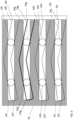
- Figures 5 to 7 are schematic projections of the output sleeve 18 showing all four of the first and second guides 22, 24 and the earth guides 26 of the actuator 2 of Figure 4 .
- Figure 5 shows the first components 14 and second components 16 when the first and second nuts 10, 12 are at the position shown in Figure 1 .
- the first and second nuts 10, 12 are retracted so as to be at the ends of their respective threaded portions closest to each other. In this position, the actuator is at one end of its stroke.
- each first component 14f, 14g, 14h, 14i When the driver 24 is actuated, the shaft 4 rotates, causing each first component 14f, 14g, 14h, 14i to move along its respective first guide 22f, 22g, 22h, 22i and its respective earth guide 26f, 26g, 26h, 26i and away from its respective associated second component 16f, 16g, 16h, 16i.
- rotation of the shaft 4 also causes each second component 16f, 16g, 16h, 16i to move along its respective second guide 24f, 24g, 24h, 24i and its respective earth guide 26f, 26g, 26h, 26i and away from its respective associated first component 14f, 14g, 14h, 14i.
- the output sleeve 18 is caused to rotate in a first circumferential direction (as shown by the arrow A) by the movement of the first and second components 14f, 14g, 14h, 14i, 16f, 16g, 16h, 16i away from each other.
- Figure 6 shows the first components 14f, 14g, 14h, 14i and second components 16f, 16g, 16h, 16i when the first and second nuts 10, 12 are at a position approximately midway through the stroke of the actuator, in other words when the first and second nuts 10, 12 are approximately midway along their respective threaded portions 6, 8.
- Figure 7 shows the first components 14f, 14g, 14h, 14i and second components 16f, 16g, 16h, 16i when the first and second nuts 10, 12 have reached the end of the stroke of the actuator 2, in other words when the first and second nuts 10, 12 are approximately at the end of their respective threaded portions 6, 8 and are as far apart as they can get.
- the driver 26 can be reversed so as to rotate the shaft 4 in the opposite direction, thus causing each first component 14f, 14g, 14h, 14i to move along its respective first guide 22f, 22g, 22h, 22i and its respective earth guide 26f, 26g, 26h, 26i and towards its respective associated second component 16f, 16g, 16h, 16i.
- rotation of the shaft also causes each second component 16f, 16g, 16h, 16i to move along its respective second guide 24f, 24g, 24h, 24i and its respective earth guide 26f, 26g, 26h, 26i and towards its respective associated first component 14f, 14g, 14h, 14i.
- both the first guides 22f, 22g, 22h, 22i and the second guides 24f, 24g, 24h, 24i are angled such that motion of the first components 14f, 14g, 14h, 14i and second components 16f, 16g, 16h, 16i along the guides has a component in the same circumferential direction
- the output sleeve 18 is caused to rotate in a second circumferential direction which is opposite to the first circumferential direction shown by A in Figure 5 (as shown by the arrow B in Figure 7 ) by the movement of the first and second components 14, 16f, 16g, 16h, 16i towards each other.
- the rotation of the output sleeve 18 in either circumferential direction can be used to drive the rotation of any suitable component.
- the rotation may be output via suitable means such as the output spline 34 of the example of Figure 1 .
- the rotary actuator may be used in an aircraft (not shown), for example to move a control surface (not shown) of the aircraft such as, for example, a control surface provided on the aircraft wing.
- the external diameter of the actuator 2 may be between about 60 and 70mm, for example about 65mm.
- the overall speed reduction ratio is a function of the pitch of the first and second threaded portions together with the lead angle of the guides.
- an overall mechanical advantage between the rotational speed of the driver and the rotational speed of the output sleeve of between 250: 1 and 500:1 may be achieved.
- the actuator can provide output rotation in either circumferential direction.
- the output rotation range may be possibly between - 90 and + 90 degrees and typically between about -20° to +20°.
- a bidirectional rotary actuator can be provided.
- the actuator By providing the first and second components which move in opposite directions to each other to drive rotation of the actuator, the actuator according to the disclosure allows internal axial loads to be contained within the actuator or to cancel each other out.
- the bearings 50, 52 which support the output sleeve 18 within the earth sleeve 20 may need to take very little force and so can be made smaller and lighter than would otherwise be the case.
- first and second components 14, 16 against their respective first and second guides 22, 24 will limit the output torque which may be achieved as, if the contact stress is too high, the guides may become deformed.
- the number of first and second components provided will reduce this stress such that an actuator having a greater number of first and second guides 22, 24 provided on the output sleeve 18 may be capable of outputting a higher torque.
Landscapes
- Engineering & Computer Science (AREA)
- General Engineering & Computer Science (AREA)
- Mechanical Engineering (AREA)
- Automation & Control Theory (AREA)
- Aviation & Aerospace Engineering (AREA)
- Transmission Devices (AREA)
Abstract
Description
- The present disclosure relates to rotary actuators such as for example, rotary actuators for use in aircraft controls.
- The present disclosure relates to rotary actuators including, but not limited to, rotary electromechanical actuators. Such actuators may be used to actuate control surfaces as used on aircraft.
- In some applications such as, for example, in the aerospace industry, there is a need to produce rotary actuators which facilitate smaller installation envelopes and which provide fast responses to commands.
- According to a first aspect of this disclosure, there is provided a rotary actuator comprising: a shaft; a first threaded portion and a second threaded portion formed on the shaft and axially spaced from each other; a first nut mounted for movement along the first threaded portion; a second nut mounted for movement along the second threaded portion; a plurality of first components extending radially outward from the first nut; a plurality of second components extending radially outward from the second nut; an earth sleeve extending around the shaft and the first and second nuts; and an output sleeve extending around the shaft and the first and second nuts, wherein the shaft is configured to be driven to rotate about a longitudinal axis thereof relative to the earth sleeve, wherein the earth sleeve comprises a plurality of axially extending earth guides, wherein the output sleeve comprises a plurality of first guides and a plurality of second guides, wherein each first component engages with a respective first guide and a respective earth guide for movement there along, wherein each second component engages with a respective second guide and a respective earth guide for movement there along, wherein the first and second threaded portions are threaded so as to cause the first and second nuts to move along the shaft in opposite directions to each other on rotation of the shaft, wherein the plurality of first guides and the plurality of second guides are configured such that movement of the plurality of first and second components along the respective guides as the shaft rotates drives rotation of the output sleeve.
- In any example of the disclosure, the actuator may comprise a driver for driving rotation of the shaft.
- In any example of the disclosure, the driver may be an electric motor.
- In any example of the disclosure, the first threaded portion may be one of a left handed or right handed thread, and the second threaded portion may be the other of a left handed or right handed thread.
- In any example of the disclosure, the plurality of first guides and the plurality of second guides may be angled relative to the longitudinal axis.
- In any example of the disclosure, each of the plurality of first guides may be angled equally relative to the longitudinal axis and / or each of the plurality of second guides may be angled equally relative to the longitudinal axis.
- In any example of the disclosure, the angle of the plurality of first guides relative to the longitudinal axis may be equal and opposite to the angle of the plurality of second guides relative to the longitudinal axis.
- In any example of the disclosure, the plurality of first guides may be axially spaced from the plurality of second guides.
- In any example of the disclosure, the rotary actuator may comprise or consist of an equal number of first components, second components, first guides and second guides, wherein, optionally, the equal number is two, three, four or six.
- In any example of the disclosure, each first guide and each second guide may comprise a track and each first component and each second component may include a roller engaged with a respective track.
- In any example of the disclosure, each earth guide may comprise an earth track or first and second axially spaced earth tracks, and each first component and each second component may include an earth roller engaged with the respective earth track or the respective first and second axially spaced earth tracks.
- In any example of the disclosure, the output sleeve may be rotatable relative to the earth sleeve.
- In any example of the disclosure, the output sleeve may be radially outward of the earth sleeve, or the output sleeve may be radially inward of the earth sleeve.
- In any example of the disclosure, the rotary actuator may be configured such that the axial forces generated by each first component moving along each first guide are approximately equal and opposite to the axial forces generated by each second component moving along each second guide.
- According to a further aspect of this disclosure, an aircraft may be provided, the aircraft comprising: a control surface; and a rotary actuator according to any example of the disclosure, wherein the rotary actuator is configured to move the control surface relative to the aircraft.
- Certain examples of the disclosure will now be described by way of example only and with reference to the accompanying drawings in which:
-
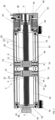
Figure 1 is a cross sectional view showing an actuator according to an example of the disclosure; -
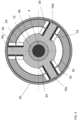
Figure 2 is a radial cross sectional view of the actuator ofFigure 1 , taken along line A-A ofFigure 1 and not taken to scale; -
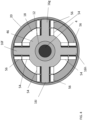
Figure 3 is a radial cross sectional view of an actuator similar to that ofFigure 1 and not taken to scale; -
Figure 4 is a radial cross sectional view of an actuator similar to that ofFigure 1 , taken along line A-A ofFigure 1 and not taken to scale; and -
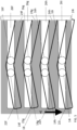
Figures 5 to 7 provide a schematic representation of the movement of each first and second component of an actuator according to the disclosure along respective first and second guides. - In any example, and referring to the
rotary actuator 2 shown inFigure 1 , the disclosure may provide arotary actuator 2 which has ashaft 4 configured to be driven to rotate about a longitudinal axis X-X thereof. Theshaft 4 includes a first threadedportion 6 and a second threadedportion 8 formed on theshaft 4. The first threadedportion 6 is axially spaced from second threadedportion 8. Afirst nut 10 is provided on the first threadedportion 6. Asecond nut 12 is provided on the second threadedportion 8. A plurality offirst components 14 extend radially outward from thefirst nut 10. A plurality ofsecond components 16 extend radially outward from thesecond nut 12. Anoutput sleeve 18 extends around theshaft 4 and the first andsecond nuts earth sleeve 20 also extends around theshaft 4 and the first andsecond nuts output sleeve 18 such that the output sleeve extends around the earth sleeve. However, in the examples shown in the drawings, theearth sleeve 20 is radially outward of theoutput sleeve 18. In other words, at least in some examples, theearth sleeve 20 extends around theshaft 4, the first andsecond nuts output sleeve 18. - The
output sleeve 18 includes a plurality offirst guides 22 and a plurality of second guides 24 (as seen inFigure 2 which is a radial cross section taken along line A-A ofFigure 1 and described in further detail below). - The
earth sleeve 20 includes a plurality ofearth guides 26. Theearth guides 26 are formed in or on theearth sleeve 20 and extend axially or substantially parallel to the longitudinal axis X-X of theshaft 4. It will be understood that in an example of the disclosure, substantially parallel to may mean within + or - 5 ° of exactly parallel to the longitudinal axis. The earth guides may function to maintain the first andsecond nuts earth sleeve 20 as will become apparent from the description below. - Each
first component 14 of the plurality offirst components 14 engages with a respective first guide of the plurality offirst guides 22 and with a respective earth guide of the plurality ofearth guides 26 for movement there along. Each second component of the plurality ofsecond components 16 engages with a respective second guide of the plurality ofsecond guides 24 and with a respective earth guide of the plurality ofearth guides 26 for movement there along. The first and second threadedportions second nuts shaft 4 in opposite directions to each other on rotation of theshaft 4. It will be understood that the first andsecond nuts shaft 4. The first andsecond guides second components second guides shaft 4 rotates drives rotation of theoutput sleeve 18. In any example of the disclosure, the rotation of theoutput sleeve 18 may be relative to theearth sleeve 20. In any example of the disclosure, the plurality offirst guides 22 and the plurality ofsecond guides 24 may be helical. - First and second axially spaced earth guides could be provided for receiving the respective first and second components but in other examples, only a single,
continuous earth guide 26 may be provided for each corresponding set of first and second components. In such examples, the continuous earth guide may extend along the full axial extent of the plurality of first andsecond guides - Thus, each of the first and
second components second guides - In any example of the disclosure, the
rotary actuator 2 may include adriver 26 for driving rotation of theshaft 4. The driver can for example be a hydraulic driver or an electric motor (as shown in the example ofFigure 1 ). Arotary output 28 of thedriver 26 can be connected to theshaft 4 to drive rotation thereof. In any example of the disclosure therefore, theshaft 4 can be driven to rotate at the same speed as the rotary speed of the driver output. - A
connection 30 to a suitable power source (such as an electrical connection to a mains power supply or battery for example) is provided for thedriver 26. In one example, thedriver 26 may be a 24V or a 48V motor capable of driving rotation of theshaft 4 between 1000 and 3000rpm. - In any example of the disclosure, the
shaft 4 and theoutput sleeve 18 can be arranged such that the longitudinal axis (not shown) of theoutput sleeve 18 extends parallel to the longitudinal axis X-X of theshaft 4. In any example and as shown inFigure 1 , theshaft 4 and theoutput sleeve 18 can be coaxial. - The
output sleeve 18 can form a housing which can be closed at a firstaxial end thereof 32. The housing can incorporate any suitable arrangement for driving output torque. In the example shown inFigure 1 , the arrangement for driving output torque comprises anoutput spline 34 at the firstaxial end 32. Theshaft 4 can be mounted to the housing at the firstaxial end 32 thereof by one ormore bearings 36. In the example shown, the one ormore bearings 36 are provided in arecess 38 in the housing so as to extend between an outer circumferential surface of theshaft 4 and the housing. - The
driver 24 can be mounted in adriver housing 40. Thedriver housing 40 may be provided at the opposite axial end of theoutput sleeve 18 from the firstaxial end 32 and may act to close the housing at the secondaxial end 42 thereof. Theshaft 4 can be mounted to therotary output 28 for rotation therewith and therotary output 28 can be mounted to thedriver housing 40 by one ormore bearings 44. In the example shown, the one ormore bearings 44 include two axially spaced bearings supporting therotary output 28 within thedriver housing 40. - As described above, the
shaft 4 includes a first threadedportion 6 and a second, axially spaced threadedportion 8 formed on theshaft 4. In any example of the disclosure, theshaft 4 can be rotated in either a clockwise or an anti-clockwise direction. The first threadedportion 6 may have either a left handed or a right handed thread. The second threadedportion 8 has the other of a left handed or a right handed thread. In other words, the first and second threadedportions shaft 4 is rotated in one of the clockwise or anti-clockwise directions, thefirst nut 10 will move axially along the first threadedportion 6 in a first direction and, at the same time, thesecond nut 12 will move axially along the second threadedportion 8 in a second direction, opposite to the first direction. Rotation of theshaft 4 in the other of the clockwise or anti-clockwise directions will cause thefirst nut 10 to move axially along the first threadedportion 6 in the second, opposite direction and, at the same time, thesecond nut 12 to move axially along the second threadedportion 8 in the first direction. - The first threaded
portion 6 and the second threadedportion 8 on theshaft 4 may have the same pitch to provide the same speed of movement of the first andsecond nuts portion 6 and the second threadedportion 8 may have a diameter of about 8 to 16mm and a fine pitch, typically of about 1 to 2 mm, to provide a relatively slow speed of movement or translation of the first andsecond nuts shaft 4. - It will be understood that, in any example of the disclosure, the first threaded
portion 6 and the second threadedportion 8 may form respective ball screws and the first andsecond nuts portion 6 and the second threadedportion 8 may form respective roller screws and the first andsecond nuts portion 6 and the second threadedportion 8 may form respective lead screws and the first andsecond nuts - As described above, a plurality of
first components 14 are provided which extend radially outward from thefirst nut 10. A plurality ofsecond components 16 are also provided which extend radially outward from thesecond nut 12. In some examples of the disclosure and as shown in the example ofFigure 2 , two first components (not shown) and twosecond components second components - Other numbers and arrangements of first components and second components can also be provided, including three, four, five or six of each of the first components and second components. It will be understood that in any of these arrangements, the first components and second components can be evenly distributed around the shaft. For example therefore, where three first components (not shown) and three
second components Figure 3 , the angle between each of the first components and between each of the second components may be about 120°. Or, where four first components (not shown) and foursecond components Figure 4 , the angle between each of the first components and between each of thesecond components - The plurality of first and
second components second nut second components annular part 46 so as to extend radially outwardly therefrom. Theannular part 46 can be concentric with theshaft 4 and fixed to the radially outer circumferential surface of the first orsecond nut annular part 46 could be formed integrally with the first orsecond nut Figures 1 and2 , twofirst components 14 are provided on oneannular part 46 and twosecond components 16 are provided on anotherannular part 46. Each of the first and second components may be acylindrical pin annular part 46 such that eachpin - In any arrangement as described above, a respective
first guide 22 for engagement with eachfirst component 14 is provided. Further, a respectivesecond guide 24 for engagement with eachsecond component 16 is provided. For example therefore, where two first components and two second components are provided, twofirst guides 22 and twosecond guides 24 will be provided. At any section through theoutput sleeve 18, the twofirst guides 22 may be on opposite sides of theoutput sleeve 18, spaced by 180° from each other and the twosecond guides 24 will be on opposite sides of theoutput sleeve 18, spaced by 180° from each other. Similarly, where three first components and three second components are provided, three first guides and three second guides will be provided. Or, where four first components and four second components are provided as in the example shown inFigures 4 to 7 , fourfirst guides 22 and foursecond guides 24 will be provided. At any radial section through theoutput sleeve 18, the fourfirst guides 22 may be spaced by about 90° from each other and the foursecond guides 24 may be spaced by about 90° from each other. - It will be understood that in any example, each of the first guides 22 may extend parallel or substantially parallel to each other. In a similar manner, each of the second guides 24 may extend parallel or substantially parallel to each other.
- As seen in
Figure 1 , theoutput sleeve 18 can be mounted to theearth sleeve 20 bybearings output sleeve 18 such that theoutput sleeve 18 can rotate relative to theearth sleeve 20. Thebearings - In any of the examples shown in which each of the first and
second components example pins Figure 2 ), each pin can include a roller and an earth roller (for example, track roller assemblies) mounted radially adjacent to each other on the pin to form a radiallyinner roller 54 and a radiallyouter earth roller 56. Each radiallyinner roller 54 provided on a pin of one of thefirst components 14 engages with a respective one of the first guides 22. Each radiallyinner roller 54 provided on a pin of one of thesecond components 16 engages with a respective one of the second guides 24. In addition, each radiallyouter earth roller 56 provided on a pin of one of thefirst components 14 engages with a respective one of the earth guides 26. Each radiallyouter earth roller 56 provided on a pin of one of thesecond components 16 engages with a respective one of the earth guides 26 (which may for example be earth tracks). This causes rotation of theoutput sleeve 18 as theshaft 4 rotates. - The
guides second component second components rollers guides rollers - It will be understood that, in any example of the disclosure, the first and
second guides second guides - Each of the
guides 22 may extend helically around a part ofsleeve 18 circumference. - The first guides 22 can be angled relative to the axis X-X so as to form part of a helix extending along the longitudinal extent of the
actuator 2 over the extent of the first threadedportion 6. In the example shown, eachfirst guide 22 is angled relative to the axis X-X at about 15°. The second guides 24 can be angled relative to the axis X-X so as to form part of a helix extending in an opposite direction along the longitudinal extent of theactuator 2 over the extent of the second threadedportion 8. In the example shown, eachsecond guide 24 is angled relative to the axis X-X at about 15°. It will further be understood that first andsecond guides actuator 2. Thus, if developed eachfirst guide 22 would provide a fundamental helical form or thread extending around theoutput sleeve 18 in a first direction, whereas eachsecond guide 24 would provide a fundamental helical form or thread extending around theoutput sleeve 18 in a second, opposite direction. - Operation of an
actuator 2 such as the actuator ofFigures 1 and4 will now be described with reference toFigures 5 to 7 which are schematic projections of theoutput sleeve 18 showing all four of the first andsecond guides actuator 2 ofFigure 4 .Figure 5 shows thefirst components 14 andsecond components 16 when the first andsecond nuts Figure 1 . In other words, the first andsecond nuts - When the
driver 24 is actuated, theshaft 4 rotates, causing eachfirst component first guide respective earth guide second component shaft 4 also causes eachsecond component second guide respective earth guide first component first guides second guides first components 14 andsecond components 16 along the guides has a component in the same circumferential direction, theoutput sleeve 18 is caused to rotate in a first circumferential direction (as shown by the arrow A) by the movement of the first andsecond components -
Figure 6 shows thefirst components second components second nuts second nuts portions -
Figure 7 shows thefirst components second components second nuts actuator 2, in other words when the first andsecond nuts portions - Once the end of the actuator stroke has been reached, or at any other position or stage in the actuator stroke, the
driver 26 can be reversed so as to rotate theshaft 4 in the opposite direction, thus causing eachfirst component first guide respective earth guide second component second component second guide respective earth guide first component first guides second guides first components second components output sleeve 18 is caused to rotate in a second circumferential direction which is opposite to the first circumferential direction shown by A inFigure 5 (as shown by the arrow B inFigure 7 ) by the movement of the first andsecond components - In any example of the disclosure, the rotation of the
output sleeve 18 in either circumferential direction can be used to drive the rotation of any suitable component. At least in some examples, the rotation may be output via suitable means such as theoutput spline 34 of the example ofFigure 1 . In any example, the rotary actuator may be used in an aircraft (not shown), for example to move a control surface (not shown) of the aircraft such as, for example, a control surface provided on the aircraft wing. - In any example of the disclosure, the external diameter of the
actuator 2 may be between about 60 and 70mm, for example about 65mm. - It will be understood that, in actuators according to the disclosure, including that of the example shown, the overall speed reduction ratio is a function of the pitch of the first and second threaded portions together with the lead angle of the guides. In any example of the disclosure, an overall mechanical advantage between the rotational speed of the driver and the rotational speed of the output sleeve of between 250: 1 and 500:1 may be achieved. It will be understood that the actuator can provide output rotation in either circumferential direction. The output rotation range may be possibly between - 90 and + 90 degrees and typically between about -20° to +20°.
- In any example of the disclosure, a bidirectional rotary actuator can be provided.
- By providing the first and second components which move in opposite directions to each other to drive rotation of the actuator, the actuator according to the disclosure allows internal axial loads to be contained within the actuator or to cancel each other out. Thus, for example, the
bearings output sleeve 18 within theearth sleeve 20 may need to take very little force and so can be made smaller and lighter than would otherwise be the case. - It will further be understood that the contact stress of the first and
second components second guides second guides output sleeve 18 may be capable of outputting a higher torque. - While the disclosure has been described in detail in connection with only a limited number of examples, it should be readily understood that the disclosure is not limited to such disclosed examples. Rather, the disclosure can be modified to incorporate any number of variations, alterations, substitutions or equivalent arrangements not heretofore described, but which are commensurate with the scope of disclosure. Additionally, while various examples of the disclosure have been described, it is to be understood that aspects of the disclosure may include only some of the described examples. Accordingly the disclosure is not to be seen as limited by the foregoing description, but is only limited by the scope of the appended claims.
Claims (15)
- A rotary actuator comprising:a shaft;a first threaded portion and a second threaded portion formed on the shaft and axially spaced from each other;a first nut mounted for movement along the first threaded portion;a second nut mounted for movement along the second threaded portion;a plurality of first components extending radially outward from the first nut;a plurality of second components extending radially outward from the second nut;an earth sleeve extending around the shaft and the first and second nuts; andan output sleeve extending around the shaft and the first and second nuts,wherein the shaft is configured to be driven to rotate about a longitudinal axis thereof relative to the earth sleeve,wherein the earth sleeve comprises a plurality of axially extending earth guides,wherein the output sleeve comprises a plurality of first guides and a plurality of second guides,wherein each first component engages with a respective first guide and a respective earth guide for movement there along,wherein each second component engages with a respective second guide and a respective earth guide for movement there along,wherein the first and second threaded portions are threaded so as to cause the first and second nuts to move along the shaft in opposite directions to each other on rotation of the shaft,wherein the plurality of first guides and the plurality of second guides are configured such that movement of the plurality of first and second components along the respective guides as the shaft rotates drives rotation of the output sleeve.
- A rotary actuator as claimed in claim 1, comprising a driver for driving rotation of the shaft.
- A rotary actuator as claimed in claim 2, wherein the driver is an electric motor.
- A rotary actuator as claimed in claim 1, 2 or 3, wherein the first threaded portion is one of a left handed or right handed thread, and wherein the second threaded portion is the other of a left handed or right handed thread.
- A rotary actuator as claimed in any preceding claim, wherein the plurality of first guides and the plurality of second guides are angled relative to the longitudinal axis.
- A rotary actuator as claimed in any preceding claim, wherein each of the plurality of first guides are angled equally relative to the longitudinal axis, and / or
wherein each of the plurality of second guides are angled equally relative to the longitudinal axis. - A rotary actuator as claimed in any preceding claim, wherein the angle of the plurality of first guides relative to the longitudinal axis is equal and opposite to the angle of the plurality of second guides relative to the longitudinal axis.
- A rotary actuator as claimed in any preceding claim, wherein the plurality of first guides are axially spaced from the plurality of second guides.
- A rotary actuator as claimed in any preceding claim, comprising or consisting of an equal number of first components, second components, first guides and second guides, wherein, optionally, the equal number is two, three, four or six.
- A rotary actuator as claimed in any preceding claim, wherein each first guide and each second guide comprises a track and wherein each first component and each second component includes a roller engaged with a respective track.
- A rotary actuator as claimed in any preceding claim, wherein each earth guide comprises an earth track or first and second axially spaced earth tracks, and
wherein each first component and each second component includes an earth roller engaged with the respective earth track or the respective first and second axially spaced earth tracks. - A rotary actuator as claimed in any preceding claim, wherein the output sleeve is rotatable relative to the earth sleeve.
- A rotary actuator as claimed in any preceding claim, wherein the output sleeve is radially outward of the earth sleeve, or
wherein the output sleeve is radially inward of the earth sleeve. - A rotary actuator as claimed in any preceding claim, wherein the rotary actuator is configured such that the axial forces generated by each first component moving along each first guide are approximately equal and opposite to the axial forces generated by each second component moving along each second guide.
- An aircraft comprising:a control surface; anda rotary actuator as claimed in any preceding claim,wherein the rotary actuator is configured to move the control surface relative to the aircraft.
Priority Applications (3)
| Application Number | Priority Date | Filing Date | Title |
|---|---|---|---|
| EP23275045.5A EP4435292B1 (en) | 2023-03-23 | 2023-03-23 | TURNTABLE |
| CA3221473A CA3221473A1 (en) | 2023-03-23 | 2023-11-29 | Rotary actuator |
| US18/615,247 US12429118B2 (en) | 2023-03-23 | 2024-03-25 | Rotary actuator |
Applications Claiming Priority (1)
| Application Number | Priority Date | Filing Date | Title |
|---|---|---|---|
| EP23275045.5A EP4435292B1 (en) | 2023-03-23 | 2023-03-23 | TURNTABLE |
Publications (2)
| Publication Number | Publication Date |
|---|---|
| EP4435292A1 true EP4435292A1 (en) | 2024-09-25 |
| EP4435292B1 EP4435292B1 (en) | 2025-12-31 |
Family
ID=85726645
Family Applications (1)
| Application Number | Title | Priority Date | Filing Date |
|---|---|---|---|
| EP23275045.5A Active EP4435292B1 (en) | 2023-03-23 | 2023-03-23 | TURNTABLE |
Country Status (3)
| Country | Link |
|---|---|
| US (1) | US12429118B2 (en) |
| EP (1) | EP4435292B1 (en) |
| CA (1) | CA3221473A1 (en) |
Citations (3)
| Publication number | Priority date | Publication date | Assignee | Title |
|---|---|---|---|---|
| JPH0473450A (en) * | 1990-07-16 | 1992-03-09 | T H K Kk | Ball screw unit and extension contraction device utilizing ball screw unit |
| JPH05332416A (en) * | 1992-05-27 | 1993-12-14 | Sankyo Seiki Mfg Co Ltd | Single shaft combined action unit |
| US20150300465A1 (en) * | 2012-11-05 | 2015-10-22 | Telerobot S.P.A. | Industrial automation device |
Family Cites Families (4)
| Publication number | Priority date | Publication date | Assignee | Title |
|---|---|---|---|---|
| US5311788A (en) * | 1991-09-25 | 1994-05-17 | Nsk Ltd. | Linear working unit |
| FR2946617B1 (en) | 2009-06-10 | 2012-11-16 | Sagem Defense Securite | DEVICE FOR ACTUATING AN AIRCRAFT GOVERNMENT. |
| EP3159577B1 (en) | 2014-11-21 | 2020-11-04 | Hamilton Sundstrand Corporation | A bearing system for use in actuator for driving a rotatable component and a corresponding method |
| CN110588955B (en) | 2019-09-03 | 2024-04-09 | 中国空空导弹研究院 | A ball screw pair rotary actuator device |
-
2023
- 2023-03-23 EP EP23275045.5A patent/EP4435292B1/en active Active
- 2023-11-29 CA CA3221473A patent/CA3221473A1/en active Pending
-
2024
- 2024-03-25 US US18/615,247 patent/US12429118B2/en active Active
Patent Citations (3)
| Publication number | Priority date | Publication date | Assignee | Title |
|---|---|---|---|---|
| JPH0473450A (en) * | 1990-07-16 | 1992-03-09 | T H K Kk | Ball screw unit and extension contraction device utilizing ball screw unit |
| JPH05332416A (en) * | 1992-05-27 | 1993-12-14 | Sankyo Seiki Mfg Co Ltd | Single shaft combined action unit |
| US20150300465A1 (en) * | 2012-11-05 | 2015-10-22 | Telerobot S.P.A. | Industrial automation device |
Also Published As
| Publication number | Publication date |
|---|---|
| US12429118B2 (en) | 2025-09-30 |
| EP4435292B1 (en) | 2025-12-31 |
| CA3221473A1 (en) | 2025-07-02 |
| US20240318707A1 (en) | 2024-09-26 |
Similar Documents
| Publication | Publication Date | Title |
|---|---|---|
| US3803927A (en) | Coaxial force and movement mechanism for a machine tool | |
| EP1548327B1 (en) | Linear actuator | |
| US9021903B2 (en) | Linear actuator | |
| US9088185B2 (en) | Electromechanical actuator, electromechanical-actuator power disconnection method, and electromechanical-actuator power disconnection apparatus | |
| EP0448711A4 (en) | Jam resistant ball screw actuator | |
| US7007566B2 (en) | Actuator for a motor vehicle transmission | |
| US2844044A (en) | Antifriction screw device | |
| EP4042039B1 (en) | Rotary mechanical screw transmission | |
| EP3467347A1 (en) | Linear actuator | |
| US11639747B2 (en) | Linear actuator | |
| EP3023671B1 (en) | Rotary actuator and a method of driving the same | |
| EP3406936B1 (en) | Improved planetary screw mechanism | |
| EP4435292B1 (en) | TURNTABLE | |
| EP4160048B1 (en) | Ball screw rotary actuator with ball cage | |
| EP3611374A1 (en) | Rotary actuator | |
| KR102817552B1 (en) | Linear actuator and manufacturing method | |
| CN111271424A (en) | Actuating mechanism with satellite roller screw mechanism | |
| EP4382770A1 (en) | Linear actuator and method of operating the same | |
| BR102023026027A2 (en) | ROTARY ACTUATOR, AND, AIRCRAFT | |
| RU2766637C9 (en) | Drive structure | |
| US20250145276A1 (en) | Linear actuator for a flight control surface | |
| CN223777007U (en) | Auxiliary installation tool | |
| RU2735979C1 (en) | Linear electric drive |
Legal Events
| Date | Code | Title | Description |
|---|---|---|---|
| PUAI | Public reference made under article 153(3) epc to a published international application that has entered the european phase |
Free format text: ORIGINAL CODE: 0009012 |
|
| STAA | Information on the status of an ep patent application or granted ep patent |
Free format text: STATUS: THE APPLICATION HAS BEEN PUBLISHED |
|
| AK | Designated contracting states |
Kind code of ref document: A1 Designated state(s): AL AT BE BG CH CY CZ DE DK EE ES FI FR GB GR HR HU IE IS IT LI LT LU LV MC ME MK MT NL NO PL PT RO RS SE SI SK SM TR |
|
| STAA | Information on the status of an ep patent application or granted ep patent |
Free format text: STATUS: REQUEST FOR EXAMINATION WAS MADE |
|
| 17P | Request for examination filed |
Effective date: 20250304 |
|
| GRAP | Despatch of communication of intention to grant a patent |
Free format text: ORIGINAL CODE: EPIDOSNIGR1 |
|
| STAA | Information on the status of an ep patent application or granted ep patent |
Free format text: STATUS: GRANT OF PATENT IS INTENDED |
|
| INTG | Intention to grant announced |
Effective date: 20250725 |
|
| GRAS | Grant fee paid |
Free format text: ORIGINAL CODE: EPIDOSNIGR3 |
|
| GRAA | (expected) grant |
Free format text: ORIGINAL CODE: 0009210 |
|
| STAA | Information on the status of an ep patent application or granted ep patent |
Free format text: STATUS: THE PATENT HAS BEEN GRANTED |
|
| AK | Designated contracting states |
Kind code of ref document: B1 Designated state(s): AL AT BE BG CH CY CZ DE DK EE ES FI FR GB GR HR HU IE IS IT LI LT LU LV MC ME MK MT NL NO PL PT RO RS SE SI SK SM TR |
|
| REG | Reference to a national code |
Ref country code: CH Ref legal event code: F10 Free format text: ST27 STATUS EVENT CODE: U-0-0-F10-F00 (AS PROVIDED BY THE NATIONAL OFFICE) Effective date: 20251231 Ref country code: GB Ref legal event code: FG4D |
|
| REG | Reference to a national code |
Ref country code: DE Ref legal event code: R096 Ref document number: 602023010437 Country of ref document: DE |
|
| REG | Reference to a national code |
Ref country code: IE Ref legal event code: FG4D |
|
| REG | Reference to a national code |
Ref country code: LT Ref legal event code: MG9D |
|
| PG25 | Lapsed in a contracting state [announced via postgrant information from national office to epo] |
Ref country code: NO Free format text: LAPSE BECAUSE OF FAILURE TO SUBMIT A TRANSLATION OF THE DESCRIPTION OR TO PAY THE FEE WITHIN THE PRESCRIBED TIME-LIMIT Effective date: 20260331 |
|
| PG25 | Lapsed in a contracting state [announced via postgrant information from national office to epo] |
Ref country code: FI Free format text: LAPSE BECAUSE OF FAILURE TO SUBMIT A TRANSLATION OF THE DESCRIPTION OR TO PAY THE FEE WITHIN THE PRESCRIBED TIME-LIMIT Effective date: 20251231 Ref country code: HR Free format text: LAPSE BECAUSE OF FAILURE TO SUBMIT A TRANSLATION OF THE DESCRIPTION OR TO PAY THE FEE WITHIN THE PRESCRIBED TIME-LIMIT Effective date: 20251231 |
|
| PGFP | Annual fee paid to national office [announced via postgrant information from national office to epo] |
Ref country code: AT Payment date: 20260301 Year of fee payment: 4 |
|
| PG25 | Lapsed in a contracting state [announced via postgrant information from national office to epo] |
Ref country code: RS Free format text: LAPSE BECAUSE OF FAILURE TO SUBMIT A TRANSLATION OF THE DESCRIPTION OR TO PAY THE FEE WITHIN THE PRESCRIBED TIME-LIMIT Effective date: 20260331 |
|
| PG25 | Lapsed in a contracting state [announced via postgrant information from national office to epo] |
Ref country code: LV Free format text: LAPSE BECAUSE OF FAILURE TO SUBMIT A TRANSLATION OF THE DESCRIPTION OR TO PAY THE FEE WITHIN THE PRESCRIBED TIME-LIMIT Effective date: 20251231 |
|
| PG25 | Lapsed in a contracting state [announced via postgrant information from national office to epo] |
Ref country code: BG Free format text: LAPSE BECAUSE OF FAILURE TO SUBMIT A TRANSLATION OF THE DESCRIPTION OR TO PAY THE FEE WITHIN THE PRESCRIBED TIME-LIMIT Effective date: 20251231 |
|
| REG | Reference to a national code |
Ref country code: NL Ref legal event code: MP Effective date: 20251231 |