EP4435253A1 - An active vibration controlling device for a wind turbine - Google Patents
An active vibration controlling device for a wind turbine Download PDFInfo
- Publication number
- EP4435253A1 EP4435253A1 EP23163478.3A EP23163478A EP4435253A1 EP 4435253 A1 EP4435253 A1 EP 4435253A1 EP 23163478 A EP23163478 A EP 23163478A EP 4435253 A1 EP4435253 A1 EP 4435253A1
- Authority
- EP
- European Patent Office
- Prior art keywords
- wind turbine
- active vibration
- controlling device
- vibration controlling
- mast
- Prior art date
- Legal status (The legal status is an assumption and is not a legal conclusion. Google has not performed a legal analysis and makes no representation as to the accuracy of the status listed.)
- Withdrawn
Links
Images




Classifications
-
- F—MECHANICAL ENGINEERING; LIGHTING; HEATING; WEAPONS; BLASTING
- F03—MACHINES OR ENGINES FOR LIQUIDS; WIND, SPRING, OR WEIGHT MOTORS; PRODUCING MECHANICAL POWER OR A REACTIVE PROPULSIVE THRUST, NOT OTHERWISE PROVIDED FOR
- F03D—WIND MOTORS
- F03D7/00—Controlling wind motors
- F03D7/02—Controlling wind motors the wind motors having rotation axis substantially parallel to the air flow entering the rotor
- F03D7/0296—Controlling wind motors the wind motors having rotation axis substantially parallel to the air flow entering the rotor to prevent, counteract or reduce noise emissions
-
- F—MECHANICAL ENGINEERING; LIGHTING; HEATING; WEAPONS; BLASTING
- F03—MACHINES OR ENGINES FOR LIQUIDS; WIND, SPRING, OR WEIGHT MOTORS; PRODUCING MECHANICAL POWER OR A REACTIVE PROPULSIVE THRUST, NOT OTHERWISE PROVIDED FOR
- F03D—WIND MOTORS
- F03D13/00—Assembly, mounting or commissioning of wind motors; Arrangements specially adapted for transporting wind motor components
- F03D13/20—Arrangements for mounting or supporting wind motors; Masts or towers for wind motors
- F03D13/25—Arrangements for mounting or supporting wind motors; Masts or towers for wind motors specially adapted for offshore installation
- F03D13/256—Arrangements for mounting or supporting wind motors; Masts or towers for wind motors specially adapted for offshore installation on a floating support, i.e. floating wind motors
-
- F—MECHANICAL ENGINEERING; LIGHTING; HEATING; WEAPONS; BLASTING
- F16—ENGINEERING ELEMENTS AND UNITS; GENERAL MEASURES FOR PRODUCING AND MAINTAINING EFFECTIVE FUNCTIONING OF MACHINES OR INSTALLATIONS; THERMAL INSULATION IN GENERAL
- F16F—SPRINGS; SHOCK-ABSORBERS; MEANS FOR DAMPING VIBRATION
- F16F7/00—Vibration-dampers; Shock-absorbers
- F16F7/10—Vibration-dampers; Shock-absorbers using inertia effect
- F16F7/1005—Vibration-dampers; Shock-absorbers using inertia effect characterised by active control of the mass
-
- F—MECHANICAL ENGINEERING; LIGHTING; HEATING; WEAPONS; BLASTING
- F05—INDEXING SCHEMES RELATING TO ENGINES OR PUMPS IN VARIOUS SUBCLASSES OF CLASSES F01-F04
- F05B—INDEXING SCHEME RELATING TO WIND, SPRING, WEIGHT, INERTIA OR LIKE MOTORS, TO MACHINES OR ENGINES FOR LIQUIDS COVERED BY SUBCLASSES F03B, F03D AND F03G
- F05B2260/00—Function
- F05B2260/96—Preventing, counteracting or reducing vibration or noise
- F05B2260/964—Preventing, counteracting or reducing vibration or noise by damping means
-
- F—MECHANICAL ENGINEERING; LIGHTING; HEATING; WEAPONS; BLASTING
- F16—ENGINEERING ELEMENTS AND UNITS; GENERAL MEASURES FOR PRODUCING AND MAINTAINING EFFECTIVE FUNCTIONING OF MACHINES OR INSTALLATIONS; THERMAL INSULATION IN GENERAL
- F16F—SPRINGS; SHOCK-ABSORBERS; MEANS FOR DAMPING VIBRATION
- F16F2232/00—Nature of movement
- F16F2232/04—Rotary-to-translation conversion
-
- Y—GENERAL TAGGING OF NEW TECHNOLOGICAL DEVELOPMENTS; GENERAL TAGGING OF CROSS-SECTIONAL TECHNOLOGIES SPANNING OVER SEVERAL SECTIONS OF THE IPC; TECHNICAL SUBJECTS COVERED BY FORMER USPC CROSS-REFERENCE ART COLLECTIONS [XRACs] AND DIGESTS
- Y02—TECHNOLOGIES OR APPLICATIONS FOR MITIGATION OR ADAPTATION AGAINST CLIMATE CHANGE
- Y02E—REDUCTION OF GREENHOUSE GAS [GHG] EMISSIONS, RELATED TO ENERGY GENERATION, TRANSMISSION OR DISTRIBUTION
- Y02E10/00—Energy generation through renewable energy sources
- Y02E10/70—Wind energy
- Y02E10/72—Wind turbines with rotation axis in wind direction
Definitions
- This disclosure relates to an active vibration controlling device for a wind turbine and a wind turbine incorporating the same.
- Wind turbines and in particular floating wind turbines, are subject to vibrations caused by various environmental loads such as wind, currents, and vibrations generated by the operation of the wind turbine itself, such as the rotational speed of the rotor, which may be referred to as 1p frequency, and the vibrations induced by the blades passing in front of the mast of the wind turbine, which is generally referred to as 3p frequency since wind turbine generally comprise three blades.
- figure 1 represents the variation of force exerted on the mast by each blade passage in front of the mast of the wind turbine. This force extends perpendicularly to the axis of the mast and along the nacelle (which is orientable according to the direction of the wind) and is variable with time since it varies with the angular position of the blades.
- the structure of the wind turbine has its own natural frequencies, which depend on the sizing of the turbine, and the wind turbine must be designed such that a frequency gap is maintained between the natural frequencies of the turbine and the excitation frequencies of the environmental loads.
- This constraint is particularly harsh for floating wind turbines, as shown in the frequency diagram of figure 2 , because the allowable frequency range is limited on one hand by the 3p excitation frequency and on the other hand by the band of excitation frequencies caused by the waves.
- floating wind turbines tend to have more massive designs than terrestrial wind turbines, which leads to an increase of the 3p frequency which further narrows the range of allowable frequency range for natural frequencies.
- This disclosure improves the situation.
- One aim of the present disclosure is to propose an active vibration controlling device for a wind turbine, which is configured for counteracting vibrations occurring within the wind turbine at at least one excitation frequency.
- an aim of the present disclosure is to remove vibrations induced at the 3p excitation frequency, i.e. the vibrations induced by the blades of the wind turbine passing in front of the mast.
- an active vibration controlling device for a wind turbine having a mast, a nacelle and a plurality of rotating blades, the device comprising
- the at least one excitation frequency of the wind turbine is the frequency of the rotating blades passing in front of the mast.
- the translation axis is perpendicular to the direction of the mast of the wind turbine.
- the driving device comprises a rod-crank system.
- the active vibration controlling device further comprises an enclosure containing at least the inertial mass and driving device, and the enclosure is mounted on an outer wall of the wind turbine.
- the driving device comprises an electrical motor and an actuator
- the active vibration controlling device further comprises a source of electrical energy chosen among a battery of the active vibration controlling device and a connection interface to an electrical system of the wind turbine.
- a wind turbine comprising a mast, a nacelle and a plurality of rotating blades, the wind turbine further comprising an active vibration controlling device according to the description above.
- the active vibration controlling device is located within the nacelle.
- the wind turbine comprises a rotor rotatably mounted on the nacelle and on which are mounted the blades
- the driving device of the active vibration controlling device comprises a mechanical transmission device for drawing rotational power from the rotor, and a conversion device suitable for converting the rotational power into the oscillatory movement of the mass.
- the wind turbine comprises a rotor rotatably mounted on the nacelle and on which are mounted the blades
- the driving device of the active vibration controlling device comprises an electrical motor having an output shaft, a source of electrical energy feeding the electrical motor, chosen among an electrical system of the wind turbine and an alternator configured for converting rotational power of the rotor into electrical power
- the driving device further comprises a conversion device for converting a rotational power of the electrical motor's output shaft into the oscillatory movement of the mass.
- the mechanical transmission device comprises one of a gearbox, a toothed pulley or chain.
- the wind turbine is a floating wind turbine.
- the active vibration controlling device disclosed above enables reducing fatigue induced by vibrations on a wind turbine by urging an inertial mass according to an oscillatory movement which is opposed to oscillations produced at at least a determined excitation frequency of the wind turbine.
- the phase and frequency of the oscillatory movement of the mass may be selected in order to counteract a determined excitation frequency, for instance the 3p frequency at which the blades pass in front of the mast.
- the active vibration controlling device may be contained in an enclosure that can be mounted on an outer wall of the turbine, the electrical supply of the active vibration controlling device being provided by the generator of the wind turbine, to which the active vibration controlling device may be connected via an electrical interface. Accordingly, an active vibration controlling device may be assembled to an existing wind turbine without requiring any change in the design or manufacturing of the wind turbine.
- the wind turbine 20 may be an onshore wind turbine or an offshore wind turbine, in which case the wind turbine may be floating on a water body such as a sea or a lake, or fixed to the waterbed.
- the wind turbine comprises a mast 21 which may be generally rectilinear and extend along an axis X-X.
- the mast 21 may have a shape that is widening from the upper end where the nacelle is mounted, towards the base.
- the mast may comprise a plurality of legs joining at the upper end of the mast and assembled at their base on a common platform.
- the axix X-X of the mast is interpreted as the axis joining the upper end to the center of the base. If the mast comprises a plurality of legs, the center of the base of the mast is at the center of the basis of the legs.
- the axis X-X is supposed to extend vertically although, in particular for floating wind turbine, the axis may be offset from the vertical when the wind turbine is subject to wind or waves.
- the wind turbine also comprises a nacelle 22, mounted on top of the mast 21 and extending along an axis Y-Y, which is transverse to the axis of the mast, generally perpendicular to the axis of the mast.
- the nacelle 22 is rotatably mounted to the mast about the axis X-X of the mast, in order to be orientable according to the direction of the wind.
- the wind turbine further comprises a rotor 23, rotatably mounted on an end of the nacelle 22.
- the rotor 23 comprises a plurality of blades, for instance three blades 230. Each blade may be pivotably mounted around its respective axis.
- the nacelle 22 of the wind turbine further encloses a main shaft 24 which is rotationally fixed to the rotor 23 and is induced to rotate by the rotor, which is itself induced to rotate by the force applied by the wind on the blades.
- the main shaft 24 extends in a direction transverse to the axis of the mast, for instance perpendicular to said axis, i.e. parallel to the axis Y-Y of the nacelle.
- the angle of the main shaft may be offset by an angle, for instance of less than 10°, with respect to the axis Y-Y of the nacelle.
- the nacelle 22 may comprise a bedplate 220, forming a support for the main shaft 24, which may be mounted to the bedplate via main bearings 240, 241.
- the nacelle 22 further includes a gearbox 27 and an electrical generator 25, in particular an alternator, that converts the rotational energy of the rotor into electricity.
- the nacelle 11 of the wind turbine further comprises electrical transmission means as well as control means that are not detailed here and not shown in the figures.
- the wind turbine 20 is subject to oscillations produced at various excitation frequencies.
- Some of the excitation frequencies may be variable and hardly predictable, such as the frequency of the waves in the case of an offshore wind turbine, but some of the excitation frequencies are well known and predictable.
- the terms "3p excitation frequency” will be used to designate the frequency at which the blades pass in front of the mast, as the wind turbines generally comprise three blades, but the same wording is also applicable for a different number of blades, for instance four or five blades.
- an active vibration controlling device 10 that enables counteracting the oscillations induced on the wind turbine at at least one determined and predictable excitation frequency.
- the vibration controlling device comprises an inertial mass 11 and a driving device 12 suitable for moving the inertial mass in translation along an axis, which is transverse to the direction of the mast X-X, and preferably perpendicular to the direction of the mast.
- the translation axis of the mast may be parallel to the axis of the nacelle Y-Y.
- the driving device 12 is configured for moving the inertial mass 11 according to an oscillatory movement suitable for inducing, on the wind turbine, a load that is variable with time, in particular oscillatory, and which counteract the oscillations produced at said excitation frequency.
- the load that is produced by the motion of the mass extends parallel to the direction of motion of the mass, i.e. is extends perpendicular to the direction of the mast and parallel to the direction of the nacelle.
- active it is thus meant that the motion of the mass is actively controlled and requires a controllable source of energy for setting the desired motion.
- the frequency of the oscillatory motion of the mass is controlled to correspond to said excitation frequency
- the phase of the oscillatory motion of the mass is also controlled such that the motion of the mass induces a load in opposition of phase with the oscillations induced at said excitation frequency.
- the active vibration controlling device 10 must thus be distinguished from a passive damping device in which an inertial mass is urged to move by the movement of the structure, i.e. of the wind turbine itself, according to a frequency that is neither controlled nor predictable.
- the active vibration controlling device 10 is configured for generating a variable load counteracting the oscillations induced on the wind turbine by the motion of the blades passing in front of the mast, i.e. the oscillations induced at the 3p excitation frequency.
- the driving device 12 is configured for moving the inertial mass 11 according to an oscillatory movement having a frequency equal to the 3p excitation frequency, i.e. which is three times the rotation frequency of the rotor.
- the phase of the oscillatory movement of the inertial mass is adapted to the phase of the motion of the blades, such that the maximum axial load induced by the motion of the mass on the wind turbine occurs simultaneously to a maximum axial load induced in an opposite direction by the motion of a blade passing in front of the mast.
- the phase of the active vibration controlling device 10 is set to minimize a load variation on the mast during a full rotation of the blades.
- the driving device 12 for moving the mass along its translation axis may comprise a rod-crank system, where the rod is connected to the inertial mass and the crank is connected to a rotating shaft.
- a rod-crank system enables converting a rotational movement of a rotating shaft to which the crank is connected into a translational movement of the mass.
- the phase of the motion of the mass may therefore be set according to the angular position of the blades in order that the motion of the mass minimizes the load variation on the mast.
- the active vibration controlling device may be integrated within the wind turbine 20, preferably within the nacelle 22 of the wind turbine. Indeed, as the nacelle is rotatably mounted on the mast, the load applied to the mast by the motion of the blades depends on the orientation of the nacelle. Mounting the active vibration controlling device within the nacelle, with a translation axis of the inertial mass 11 parallel to the axis Y-Y of the nacelle or of the main shaft 24 thus ensures that the translation axis of the inertial mass is properly oriented with respect to the oscillations that are counteracted. If the active vibration controlling device 10 is mounted within the mast 21, for instance, it requires that the translation axis of the inertial mass be orientable about the axis of the mast.
- the rotor 23 of the wind turbine may be used as the source of mechanical energy for moving the inertial mass
- the driving device 12 may comprise a mechanical transmission device 121 for drawing rotational power of the rotor, and a conversion device 122 for converting the rotational power into the oscillatory movement of the mass.
- the mechanical transmission device 121 may comprise one or more gears, a toothed pulley or a chain for transmitting the rotational power of the rotor to a secondary shaft
- the conversion device 122 may comprise a rod-crank system.
- the mechanical transmission device may also be configured to apply a desired reduction ratio to the frequency of rotation of the rotor.
- the power transmission device may be configured to multiply the rotation frequency at the rotor by the number of blades (e.g. 3).
- the transmission device 121 may comprise first gears or a toothed pulley 1210 for transmitting the rotational power of the rotor to a secondary shaft 1211 extending parallel to the axis of the rotor, and second gears 1212 angled at 90°, for converting the rotational motion of the secondary shaft into a rotational motion that is perpendicular to the secondary shaft.
- the crank of the rod-crank system 122 is mounted on the gear which axis of rotation is perpendicular to the second axis, thus enabling a motion of translation of the rod and of the mass which is parallel to the axis of the rotor.
- the driving device 12 of the active vibration controlling device 10 may comprise a motor 123, in particular an electrical motor that may be fed by an electrical system of the turbine, such as a battery, an auxiliary power unit, the generator 25 of the turbine or any electrical component receiving electrical power converted from the power issued from the generator.
- the electrical motor may also be fed by the grid to which the turbine is injecting the generated power.
- the driving device may also comprise an alternator 126 configured for converting rotational power of the rotor into electrical power, and the motor 123 is fed by said alternator.
- the driving device may in that case also comprise a conversion device 122 for converting a rotational power of the motor's shaft into the oscillatory movement of the mass.
- the active vibration controlling device may also comprise a controller 14 configured to receive information relative to the operation of the wind turbine, such as the rotational speed of the rotor, or the frequency of rotation of the blades, and the phase of the motion of the blades, i.e. their angular position relative to the mast, and synchronize the oscillatory translation of the mass accordingly.
- the controller 14 can comprise a computing device comprising a processor, microprocessor, or microcontroller, a memory storing instructions executed by the computing device, and a communication interface enabling the controller to receive the above-mentioned information.
- the wind turbine 20 comprises a computing system 26 configured for controlling and monitoring the operation of the wind turbine, in particular for controlling and monitoring the generator's operation and the rotor shaft speed
- the communication interface 124 is configured for connecting the controller to said computing system, either via a wired communication (e.g. using an Ethernet cable) or a wireless communication (e.g. by Bluetooth or WiFi protocols).
- the active vibration controlling device 10 may comprise at least one additional sensor (not shown) for obtaining the above-mentioned information and providing the same to the controller 14.
- the active vibration controlling device may be positioned as close as possible to the mast so that the path of the load induced by the movement of the inertial mass is reduced.
- the active vibration controlling device may be mounted on the bedplate of the nacelle, adjacent to the main shaft.
- the active vibration controlling device 20 may be provided as a stand-alone product that may be mounted on a wind turbine after the assembly of the wind turbine, for instance during the service life of the wind turbine.
- the active vibration controlling device 20 may be provided as a stand-alone product that may be mounted on a wind turbine after the assembly of the wind turbine, for instance during the service life of the wind turbine.
- the active vibration controlling device 10 comprises an enclosure 13 in which the inertial mass 11 and driving device 12 are contained, and the enclosure 13 can be mounted on an outer wall 29 of the wind turbine, for instance on an outer wall of the nacelle.
- Figures 5a and 5b show exemplary implementations where the active vibration controlling device 20 as a stand-alone product is mounted on respectively a lower wall or an upper wall of the nacelle.
- active vibration controlling device is preferably mounted such that the translation axis of the inertial mass extends perpendicularly to the axis X-X of the mast.
- the active vibration controlling device 10 when it is provided as a stand-alone product, it preferably comprises a controller 14 as mentioned above, configured to receive information relative to the operation of the wind turbine, and which may be connected to a computing system 26 of the wind turbine and/or sensors by a communication interface 124.
- the communication between the computing system 26 and the controller 14 may either be wired (e.g. using an Ethernet cable) or wireless (e.g. by Bluetooth or WiFi protocols).
- the driving device 12 of the active vibration controlling device 10 also includes in that case a motor 123 and an actuator, such as a conversion device 122 for converting the rotational power of the motor's shaft into the translation movement of the mass.
- the motor 123 is preferably an electrical motor and the active vibration controlling device further includes a source of electrical energy, which may be either a battery, or an electrical connection 125 with the electrical generator of the wind turbine.
- the active vibration controlling device 10 as a stand-alone device may be a designed as a so-called "plug and play" system, which may be mounted on a wall of the nacelle, and optionally connected to an electrical system of the wind turbine for the supply of electrical energy, and/or to the computing system of the wind turbine for the provision of the information relative to the operation of the turbine.
- the controller 14 then controls operation of the driving device 12, and in particular of the motor 123, to drive the inertial mass 11 according to the desired oscillatory movement.
- the controller is configured to received information about the frequency of rotation and phase of the blades 230, and to control the driving device 12 to drive the inertial mass 11 according to an oscillatory movement having the same frequency as the frequency of rotation of the blades, i.e a frequency of n times the frequency of a full rotation of a blade for a n-bladed rotor, and which produces oscillations in phase opposition with the oscillations produced by the blades.
- Fig. 6 represents an example of simulation of an axial load applied to the mast of a wind turbine with and without implementing an active vibration control.
- the simulation is performed on a wind turbine having a power of 15MW, a mast weighing 860 tons, a rotor and nacelle assembly weighing 1017 tons and an inertial mass of 1.5 ton.
- Curve A represents the axial load on the mast incurred by the passage of the blades
- curve B represents the corrective inertial load incurred by the inertial mass
- curve C represents the corrective loads induced by the blades.
- an inertial mass moved with an oscillatory frequency corresponding to the 3p frequency and with a phase determined to maximize load variation reduction on the mast enables
Landscapes
- Engineering & Computer Science (AREA)
- General Engineering & Computer Science (AREA)
- Mechanical Engineering (AREA)
- Life Sciences & Earth Sciences (AREA)
- Sustainable Development (AREA)
- Sustainable Energy (AREA)
- Chemical & Material Sciences (AREA)
- Combustion & Propulsion (AREA)
- Wind Motors (AREA)
Abstract
It is disclosed an active vibration controlling device (10) for a wind turbine (20) having a mast (21), a nacelle (22) and a plurality of rotating blades (230), the device comprising
- at least one inertial mass (11), and
- a driving device (12) suitable for driving the mass in translation along an axis,
wherein the active vibration controlling device is configured for driving the mass according to an oscillatory movement suitable to generate a variable load on the wind turbine counteracting oscillations produced at at least one excitation frequency of the wind turbine.
- at least one inertial mass (11), and
- a driving device (12) suitable for driving the mass in translation along an axis,
wherein the active vibration controlling device is configured for driving the mass according to an oscillatory movement suitable to generate a variable load on the wind turbine counteracting oscillations produced at at least one excitation frequency of the wind turbine.
Description
- This disclosure relates to an active vibration controlling device for a wind turbine and a wind turbine incorporating the same.
- Wind turbines, and in particular floating wind turbines, are subject to vibrations caused by various environmental loads such as wind, currents, and vibrations generated by the operation of the wind turbine itself, such as the rotational speed of the rotor, which may be referred to as 1p frequency, and the vibrations induced by the blades passing in front of the mast of the wind turbine, which is generally referred to as 3p frequency since wind turbine generally comprise three blades.
- Those vibrations induce stress and fatigue on the structure of the wind turbine, as is apparent from
figure 1 which represents the variation of force exerted on the mast by each blade passage in front of the mast of the wind turbine. This force extends perpendicularly to the axis of the mast and along the nacelle (which is orientable according to the direction of the wind) and is variable with time since it varies with the angular position of the blades. - Furthermore, the structure of the wind turbine has its own natural frequencies, which depend on the sizing of the turbine, and the wind turbine must be designed such that a frequency gap is maintained between the natural frequencies of the turbine and the excitation frequencies of the environmental loads. This constraint is particularly harsh for floating wind turbines, as shown in the frequency diagram of
figure 2 , because the allowable frequency range is limited on one hand by the 3p excitation frequency and on the other hand by the band of excitation frequencies caused by the waves. Furthermore, floating wind turbines tend to have more massive designs than terrestrial wind turbines, which leads to an increase of the 3p frequency which further narrows the range of allowable frequency range for natural frequencies. - This disclosure improves the situation.
- One aim of the present disclosure is to propose an active vibration controlling device for a wind turbine, which is configured for counteracting vibrations occurring within the wind turbine at at least one excitation frequency. In particular, an aim of the present disclosure is to remove vibrations induced at the 3p excitation frequency, i.e. the vibrations induced by the blades of the wind turbine passing in front of the mast.
- It is proposed an active vibration controlling device for a wind turbine having a mast, a nacelle and a plurality of rotating blades, the device comprising
- at least one inertial mass, and
- a driving device suitable for driving the mass in translation along an axis,
- In embodiments, the at least one excitation frequency of the wind turbine is the frequency of the rotating blades passing in front of the mast.
- In embodiments, the translation axis is perpendicular to the direction of the mast of the wind turbine.
- In embodiments, the driving device comprises a rod-crank system.
- In embodiments, the active vibration controlling device further comprises an enclosure containing at least the inertial mass and driving device, and the enclosure is mounted on an outer wall of the wind turbine.
- In embodiments, the active vibration controlling device further comprises a controller, configured to receive information relative to the operation of the wind turbine, and to control the driving device to drive the motion of the inertial mass according to the received information.
- In embodiments, the driving device comprises an electrical motor and an actuator, and the active vibration controlling device further comprises a source of electrical energy chosen among a battery of the active vibration controlling device and a connection interface to an electrical system of the wind turbine.
- According to another aspect, it is disclosed a wind turbine comprising a mast, a nacelle and a plurality of rotating blades, the wind turbine further comprising an active vibration controlling device according to the description above.
- In embodiments, the active vibration controlling device is located within the nacelle.
- In embodiments, the wind turbine comprises a rotor rotatably mounted on the nacelle and on which are mounted the blades, and wherein the driving device of the active vibration controlling device comprises a mechanical transmission device for drawing rotational power from the rotor, and a conversion device suitable for converting the rotational power into the oscillatory movement of the mass.
- In embodiments, the wind turbine comprises a rotor rotatably mounted on the nacelle and on which are mounted the blades, wherein the driving device of the active vibration controlling device comprises an electrical motor having an output shaft, a source of electrical energy feeding the electrical motor, chosen among an electrical system of the wind turbine and an alternator configured for converting rotational power of the rotor into electrical power, and the driving device further comprises a conversion device for converting a rotational power of the electrical motor's output shaft into the oscillatory movement of the mass.
- In embodiments, the mechanical transmission device comprises one of a gearbox, a toothed pulley or chain.
- In embodiments the wind turbine is a floating wind turbine.
- The active vibration controlling device disclosed above enables reducing fatigue induced by vibrations on a wind turbine by urging an inertial mass according to an oscillatory movement which is opposed to oscillations produced at at least a determined excitation frequency of the wind turbine. In particular, the phase and frequency of the oscillatory movement of the mass may be selected in order to counteract a determined excitation frequency, for instance the 3p frequency at which the blades pass in front of the mast.
- According to an embodiment, the active vibration controlling device may be contained in an enclosure that can be mounted on an outer wall of the turbine, the electrical supply of the active vibration controlling device being provided by the generator of the wind turbine, to which the active vibration controlling device may be connected via an electrical interface. Accordingly, an active vibration controlling device may be assembled to an existing wind turbine without requiring any change in the design or manufacturing of the wind turbine.
- Other features, details and advantages will be shown in the following detailed description and on the figures, on which:
-
Fig. 1 represents the force variation from a maximum value applied on the mast of a wind turbine, due to the passage of a blade in front of the mast. -
Fig. 2 represents an example of frequency diagram applicable to a floating wind turbine, displaying the excitation frequencies of the turbine induces by the rotor and blades, as well as the frequency bands of the waves and wind. -
Fig 3a schematically represents a wind turbine integrating an active vibration controlling device according to an embodiment. -
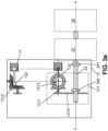
Fig. 3b schematically represents a wind turbine integrating an active vibration controlling device according to another embodiment. -
Fig. 4 schematically represents an active vibration controlling device as a stand-alone device according to an embodiment. -
Fig. 5a and 5b represent examples of possible locations of an active vibration controlling device. -
Fig. 6 represents an example of simulation of an axial load applied to the mast of a wind turbine with and without implementing an active vibration control. - With reference to
figures 3a ,3b and4 , embodiments of an active vibration controllingdevice 10 for awind turbine 20 will now be disclosed. Thewind turbine 20 may be an onshore wind turbine or an offshore wind turbine, in which case the wind turbine may be floating on a water body such as a sea or a lake, or fixed to the waterbed. - The wind turbine comprises a
mast 21 which may be generally rectilinear and extend along an axis X-X. In embodiments, themast 21 may have a shape that is widening from the upper end where the nacelle is mounted, towards the base. For instance, the mast may comprise a plurality of legs joining at the upper end of the mast and assembled at their base on a common platform. In This case, the axix X-X of the mast is interpreted as the axis joining the upper end to the center of the base. If the mast comprises a plurality of legs, the center of the base of the mast is at the center of the basis of the legs. In operation, the axis X-X is supposed to extend vertically although, in particular for floating wind turbine, the axis may be offset from the vertical when the wind turbine is subject to wind or waves. The wind turbine also comprises anacelle 22, mounted on top of themast 21 and extending along an axis Y-Y, which is transverse to the axis of the mast, generally perpendicular to the axis of the mast. Thenacelle 22 is rotatably mounted to the mast about the axis X-X of the mast, in order to be orientable according to the direction of the wind. - The wind turbine further comprises a
rotor 23, rotatably mounted on an end of thenacelle 22. Therotor 23 comprises a plurality of blades, for instance threeblades 230. Each blade may be pivotably mounted around its respective axis. Thenacelle 22 of the wind turbine further encloses amain shaft 24 which is rotationally fixed to therotor 23 and is induced to rotate by the rotor, which is itself induced to rotate by the force applied by the wind on the blades. Themain shaft 24 extends in a direction transverse to the axis of the mast, for instance perpendicular to said axis, i.e. parallel to the axis Y-Y of the nacelle. Alternatively, the angle of the main shaft may be offset by an angle, for instance of less than 10°, with respect to the axis Y-Y of the nacelle. Thenacelle 22 may comprise abedplate 220, forming a support for themain shaft 24, which may be mounted to the bedplate viamain bearings nacelle 22 further includes agearbox 27 and anelectrical generator 25, in particular an alternator, that converts the rotational energy of the rotor into electricity. Thenacelle 11 of the wind turbine further comprises electrical transmission means as well as control means that are not detailed here and not shown in the figures. - As explained above, the
wind turbine 20 is subject to oscillations produced at various excitation frequencies. Some of the excitation frequencies may be variable and hardly predictable, such as the frequency of the waves in the case of an offshore wind turbine, but some of the excitation frequencies are well known and predictable. This is the case for the 1p, 3p and 6p (etc.) excitation frequencies of the wind turbine, corresponding respectively to the frequency of rotation of the rotor, the frequency at which the blades pass in front of the mast, and its multiples. In what follows, the terms "3p excitation frequency" will be used to designate the frequency at which the blades pass in front of the mast, as the wind turbines generally comprise three blades, but the same wording is also applicable for a different number of blades, for instance four or five blades. - Accordingly, an active
vibration controlling device 10 is disclosed that enables counteracting the oscillations induced on the wind turbine at at least one determined and predictable excitation frequency. The vibration controlling device comprises aninertial mass 11 and adriving device 12 suitable for moving the inertial mass in translation along an axis, which is transverse to the direction of the mast X-X, and preferably perpendicular to the direction of the mast. The translation axis of the mast may be parallel to the axis of the nacelle Y-Y. - The driving
device 12 is configured for moving theinertial mass 11 according to an oscillatory movement suitable for inducing, on the wind turbine, a load that is variable with time, in particular oscillatory, and which counteract the oscillations produced at said excitation frequency. The load that is produced by the motion of the mass extends parallel to the direction of motion of the mass, i.e. is extends perpendicular to the direction of the mast and parallel to the direction of the nacelle. - By "active", it is thus meant that the motion of the mass is actively controlled and requires a controllable source of energy for setting the desired motion. In particular, the frequency of the oscillatory motion of the mass is controlled to correspond to said excitation frequency, and the phase of the oscillatory motion of the mass is also controlled such that the motion of the mass induces a load in opposition of phase with the oscillations induced at said excitation frequency.
- The active
vibration controlling device 10 must thus be distinguished from a passive damping device in which an inertial mass is urged to move by the movement of the structure, i.e. of the wind turbine itself, according to a frequency that is neither controlled nor predictable. - According to an embodiment, the active
vibration controlling device 10 is configured for generating a variable load counteracting the oscillations induced on the wind turbine by the motion of the blades passing in front of the mast, i.e. the oscillations induced at the 3p excitation frequency. In this case, the drivingdevice 12 is configured for moving theinertial mass 11 according to an oscillatory movement having a frequency equal to the 3p excitation frequency, i.e. which is three times the rotation frequency of the rotor. The phase of the oscillatory movement of the inertial mass is adapted to the phase of the motion of the blades, such that the maximum axial load induced by the motion of the mass on the wind turbine occurs simultaneously to a maximum axial load induced in an opposite direction by the motion of a blade passing in front of the mast. In other words, the phase of the activevibration controlling device 10 is set to minimize a load variation on the mast during a full rotation of the blades. - In embodiments, the driving
device 12 for moving the mass along its translation axis may comprise a rod-crank system, where the rod is connected to the inertial mass and the crank is connected to a rotating shaft. As commonly known, a rod-crank system enables converting a rotational movement of a rotating shaft to which the crank is connected into a translational movement of the mass. Accordingly, the position x(t) of the inertial mass is as follows:
- According to embodiments shown in
figures 3a and3b , the active vibration controlling device may be integrated within thewind turbine 20, preferably within thenacelle 22 of the wind turbine. Indeed, as the nacelle is rotatably mounted on the mast, the load applied to the mast by the motion of the blades depends on the orientation of the nacelle. Mounting the active vibration controlling device within the nacelle, with a translation axis of theinertial mass 11 parallel to the axis Y-Y of the nacelle or of themain shaft 24 thus ensures that the translation axis of the inertial mass is properly oriented with respect to the oscillations that are counteracted. If the activevibration controlling device 10 is mounted within themast 21, for instance, it requires that the translation axis of the inertial mass be orientable about the axis of the mast. - According to a first embodiment shown in
figure 3a , when the activevibration controlling device 10 is integrated within the wind turbine, therotor 23 of the wind turbine may be used as the source of mechanical energy for moving the inertial mass, and the drivingdevice 12 may comprise amechanical transmission device 121 for drawing rotational power of the rotor, and aconversion device 122 for converting the rotational power into the oscillatory movement of the mass. For instance, themechanical transmission device 121 may comprise one or more gears, a toothed pulley or a chain for transmitting the rotational power of the rotor to a secondary shaft, and theconversion device 122 may comprise a rod-crank system. The mechanical transmission device may also be configured to apply a desired reduction ratio to the frequency of rotation of the rotor. According to a non-limiting example, when the active vibration controlling device is configured to counteract oscillations produced at the 3p oscillation frequency, the power transmission device may be configured to multiply the rotation frequency at the rotor by the number of blades (e.g. 3). As shown in the example offigure 3a , thetransmission device 121 may comprise first gears or atoothed pulley 1210 for transmitting the rotational power of the rotor to asecondary shaft 1211 extending parallel to the axis of the rotor, andsecond gears 1212 angled at 90°, for converting the rotational motion of the secondary shaft into a rotational motion that is perpendicular to the secondary shaft. The crank of the rod-crank system 122 is mounted on the gear which axis of rotation is perpendicular to the second axis, thus enabling a motion of translation of the rod and of the mass which is parallel to the axis of the rotor. - Alternatively, and as shown in
figure 3b , the drivingdevice 12 of the activevibration controlling device 10 may comprise amotor 123, in particular an electrical motor that may be fed by an electrical system of the turbine, such as a battery, an auxiliary power unit, thegenerator 25 of the turbine or any electrical component receiving electrical power converted from the power issued from the generator. The electrical motor may also be fed by the grid to which the turbine is injecting the generated power. In embodiments, the driving device may also comprise an alternator 126 configured for converting rotational power of the rotor into electrical power, and themotor 123 is fed by said alternator. The driving device may in that case also comprise aconversion device 122 for converting a rotational power of the motor's shaft into the oscillatory movement of the mass. - When the active vibration controlling device comprises a
separate motor 123, it may also comprise acontroller 14 configured to receive information relative to the operation of the wind turbine, such as the rotational speed of the rotor, or the frequency of rotation of the blades, and the phase of the motion of the blades, i.e. their angular position relative to the mast, and synchronize the oscillatory translation of the mass accordingly. Thecontroller 14 can comprise a computing device comprising a processor, microprocessor, or microcontroller, a memory storing instructions executed by the computing device, and a communication interface enabling the controller to receive the above-mentioned information. In embodiments, thewind turbine 20 comprises acomputing system 26 configured for controlling and monitoring the operation of the wind turbine, in particular for controlling and monitoring the generator's operation and the rotor shaft speed, and thecommunication interface 124 is configured for connecting the controller to said computing system, either via a wired communication (e.g. using an Ethernet cable) or a wireless communication (e.g. by Bluetooth or WiFi protocols). Alternatively, the activevibration controlling device 10 may comprise at least one additional sensor (not shown) for obtaining the above-mentioned information and providing the same to thecontroller 14. - As shown in the example of
figures 3a and3b , the active vibration controlling device may be positioned as close as possible to the mast so that the path of the load induced by the movement of the inertial mass is reduced. For instance, the active vibration controlling device may be mounted on the bedplate of the nacelle, adjacent to the main shaft. - According to another embodiment shown in
figure 4 , the activevibration controlling device 20 may be provided as a stand-alone product that may be mounted on a wind turbine after the assembly of the wind turbine, for instance during the service life of the wind turbine. Thus, it is possible to provide active vibration control even for a wind turbine that has not been initially designed and produced to incorporate thesystem 10. - In that case, the active
vibration controlling device 10 comprises anenclosure 13 in which theinertial mass 11 and drivingdevice 12 are contained, and theenclosure 13 can be mounted on anouter wall 29 of the wind turbine, for instance on an outer wall of the nacelle.Figures 5a and 5b show exemplary implementations where the activevibration controlling device 20 as a stand-alone product is mounted on respectively a lower wall or an upper wall of the nacelle. In any case, active vibration controlling device is preferably mounted such that the translation axis of the inertial mass extends perpendicularly to the axis X-X of the mast. - Further, when the active
vibration controlling device 10 is provided as a stand-alone product, it preferably comprises acontroller 14 as mentioned above, configured to receive information relative to the operation of the wind turbine, and which may be connected to acomputing system 26 of the wind turbine and/or sensors by acommunication interface 124. Here also, the communication between thecomputing system 26 and thecontroller 14 may either be wired (e.g. using an Ethernet cable) or wireless (e.g. by Bluetooth or WiFi protocols). - The driving
device 12 of the activevibration controlling device 10 also includes in that case amotor 123 and an actuator, such as aconversion device 122 for converting the rotational power of the motor's shaft into the translation movement of the mass. Themotor 123 is preferably an electrical motor and the active vibration controlling device further includes a source of electrical energy, which may be either a battery, or anelectrical connection 125 with the electrical generator of the wind turbine. - Thus, the active
vibration controlling device 10 as a stand-alone device may be a designed as a so-called "plug and play" system, which may be mounted on a wall of the nacelle, and optionally connected to an electrical system of the wind turbine for the supply of electrical energy, and/or to the computing system of the wind turbine for the provision of the information relative to the operation of the turbine. Thecontroller 14 then controls operation of the drivingdevice 12, and in particular of themotor 123, to drive theinertial mass 11 according to the desired oscillatory movement. In a preferred embodiment in which the oscillatory movement is configured to counteract oscillations incurred by the blades of the wind turbine passing in front of the mast, the controller is configured to received information about the frequency of rotation and phase of theblades 230, and to control the drivingdevice 12 to drive theinertial mass 11 according to an oscillatory movement having the same frequency as the frequency of rotation of the blades, i.e a frequency of n times the frequency of a full rotation of a blade for a n-bladed rotor, and which produces oscillations in phase opposition with the oscillations produced by the blades. -
Fig. 6 represents an example of simulation of an axial load applied to the mast of a wind turbine with and without implementing an active vibration control. The simulation is performed on a wind turbine having a power of 15MW, a mast weighing 860 tons, a rotor and nacelle assembly weighing 1017 tons and an inertial mass of 1.5 ton. Curve A represents the axial load on the mast incurred by the passage of the blades, curve B represents the corrective inertial load incurred by the inertial mass and curve C represents the corrective loads induced by the blades. According to this simulation, an inertial mass moved with an oscillatory frequency corresponding to the 3p frequency and with a phase determined to maximize load variation reduction on the mast, enables -
- 10 : Active vibration controlling device
- 11: eccentric masses
- 12 : driving device
- 121 : mechanical transmission device
- 1210: first gears
- 1211 : secondary shaft
- 1212 : second gears
- 122 : conversion device
- 123 : motor
- 124 : communication interface
- 125 : electrical connection
- 126 : alternator
- 13 : enclosure
- 14 : controller
- 20 : wind turbine
- 21 : mast
- 22 : nacelle
- 23 : rotor
- 230 : blades
- 24 : main shaft
- 25 : generator
- 26 : computing system
- 27 : gearbox
- 29 : outer wall
Claims (13)
- An active vibration controlling device (10) for a wind turbine (20) having a mast (21), a nacelle (22) and a plurality of rotating blades (230), the device comprising- at least one inertial mass (11), and- a driving device (12) suitable for driving the mass in translation along an axis,wherein the active vibration controlling device is configured for driving the mass according to an oscillatory movement suitable to generate a variable load on the wind turbine counteracting oscillations produced at at least one excitation frequency of the wind turbine.
- The active vibration controlling device (10) according to claim 1, wherein the at least one excitation frequency of the wind turbine is the frequency of the rotating blades passing in front of the mast.
- The active vibration controlling device (10) according to claim 1 or 2, wherein the translation axis is perpendicular to the direction of the mast (21) of the wind turbine.
- The active vibration controlling device (10) according to any of the preceding claims, wherein the driving device (12) comprises a rod-crank system.
- The active vibration controlling device (10) according to any of the preceding claims, further comprising an enclosure (13) containing at least the inertial mass (11) and driving device (12), and the enclosure (13) is mounted on an outer wall (29) of the wind turbine (20).
- The active vibration controlling device (10) according to claim 5, further comprising a controller (14), configured to receive information relative to the operation of the wind turbine, and to control the driving device (12) to drive the motion of the inertial mass (11) according to the received information.
- The active vibration controlling device (10) according to claim 5 or 6, wherein the driving device (12) comprises an electrical motor (123) and an actuator (122), and the active vibration controlling device (10) further comprises a source of electrical energy chosen among a battery of the active vibration controlling device and a connection interface (125) to an electrical system of the wind turbine.
- A wind turbine (20) comprising a mast (21), a nacelle (22) and a plurality of rotating blades (230), the wind turbine further comprising an active vibration controlling device (10) according to any of the preceding claims.
- The wind turbine (20) according to claim 8, wherein the active vibration controlling device is located within the nacelle (22).
- The wind turbine (20) according to any of claims 8 or 9, wherein the wind turbine comprises a rotor (23) rotatably mounted on the nacelle and on which are mounted the blades, and wherein the driving device (12) of the active vibration controlling device comprises a mechanical transmission device (121) for drawing rotational power from the rotor, and a conversion device (122) suitable for converting the rotational power into the oscillatory movement of the mass.
- The wind turbine (20) according to any of claims 8 or 9, wherein the wind turbine comprises a rotor (23) rotatably mounted on the nacelle and on which are mounted the blades, wherein the driving device (12) of the active vibration controlling device comprises an electrical motor (123) having an output shaft, a source of electrical energy feeding the electrical motor, chosen among an electrical system of the wind turbine and an alternator configured for converting rotational power of the rotor into electrical power, and the driving device (12) further comprises a conversion device for converting a rotational power of the electrical motor's output shaft into the oscillatory movement of the mass.
- The wind turbine (20) according to the preceding claim, wherein the mechanical transmission device (121) comprises one of a gearbox, a toothed pulley or chain.
- The wind turbine (20) according to any of the preceding claims, wherein the wind turbine is a floating wind turbine.
Priority Applications (2)
| Application Number | Priority Date | Filing Date | Title |
|---|---|---|---|
| EP23163478.3A EP4435253A1 (en) | 2023-03-22 | 2023-03-22 | An active vibration controlling device for a wind turbine |
| PCT/EP2024/057454 WO2024194356A1 (en) | 2023-03-22 | 2024-03-20 | An active vibration controlling device for a wind turbine |
Applications Claiming Priority (1)
| Application Number | Priority Date | Filing Date | Title |
|---|---|---|---|
| EP23163478.3A EP4435253A1 (en) | 2023-03-22 | 2023-03-22 | An active vibration controlling device for a wind turbine |
Publications (1)
| Publication Number | Publication Date |
|---|---|
| EP4435253A1 true EP4435253A1 (en) | 2024-09-25 |
Family
ID=85726864
Family Applications (1)
| Application Number | Title | Priority Date | Filing Date |
|---|---|---|---|
| EP23163478.3A Withdrawn EP4435253A1 (en) | 2023-03-22 | 2023-03-22 | An active vibration controlling device for a wind turbine |
Country Status (2)
| Country | Link |
|---|---|
| EP (1) | EP4435253A1 (en) |
| WO (1) | WO2024194356A1 (en) |
Citations (2)
| Publication number | Priority date | Publication date | Assignee | Title |
|---|---|---|---|---|
| JPH0464743A (en) * | 1990-07-04 | 1992-02-28 | Shimizu Corp | Hybrid dynamic absorber |
| EP3341627B1 (en) * | 2015-08-28 | 2019-09-25 | FM Energie GmbH & Co. KG | Vibration absorber having a rotating mass |
-
2023
- 2023-03-22 EP EP23163478.3A patent/EP4435253A1/en not_active Withdrawn
-
2024
- 2024-03-20 WO PCT/EP2024/057454 patent/WO2024194356A1/en not_active Ceased
Patent Citations (2)
| Publication number | Priority date | Publication date | Assignee | Title |
|---|---|---|---|---|
| JPH0464743A (en) * | 1990-07-04 | 1992-02-28 | Shimizu Corp | Hybrid dynamic absorber |
| EP3341627B1 (en) * | 2015-08-28 | 2019-09-25 | FM Energie GmbH & Co. KG | Vibration absorber having a rotating mass |
Also Published As
| Publication number | Publication date |
|---|---|
| WO2024194356A1 (en) | 2024-09-26 |
Similar Documents
| Publication | Publication Date | Title |
|---|---|---|
| EP2803853A1 (en) | Damping wind turbine tower oscillations using gyroscopic forces | |
| EP2402597B1 (en) | Wind turbine yaw system and method of controlling the same | |
| US8779617B2 (en) | Method for reducing vibrations of a wind turbine and control system for reducing vibrations | |
| US8487464B2 (en) | Blade pitch control in a wind turbine installation | |
| EP3821125B1 (en) | Method and system for controlling a wind turbine to reduce nacelle vibration | |
| EP2466123B1 (en) | Variable speed machine assembly and method for making the same | |
| EP3575595B1 (en) | Methods and systems for operating a wind turbine | |
| EP2108827A2 (en) | Model Based Wind Turbine Drive Train Vibration Damper | |
| EP3318751A1 (en) | Damping mechanical oscillations of a wind turbine | |
| WO2010122316A1 (en) | Extracting wave energy in a wind turbine installation | |
| US20130189105A1 (en) | Vibration absorbing device for a wind turbine and method of absorbing vibrations in a wind turbine | |
| WO2019042515A1 (en) | Damping of torsional oscillation in a multi-rotor wind turbine | |
| Bracco et al. | Performance assessment of the full scale ISWEC system | |
| EP4239192A1 (en) | System and method for use of a tunable mass damper to reduce vibrations in wind turbine blades in a locked or idling condition of the rotor hub | |
| EP2554841B1 (en) | A gearbox comprising a stationary gear component formed on the basis of variable flank profiles of gear teeth | |
| CA3213937A1 (en) | Method and system for damping a wind turbine tower | |
| WO2024194356A1 (en) | An active vibration controlling device for a wind turbine | |
| EP4435252A1 (en) | An active vibration controlling device for a wind turbine | |
| US12571342B2 (en) | Engine-generator set | |
| JP2021508231A (en) | Electromechanical system and phase adjustment gear device for transmitting rotational energy | |
| US12618393B2 (en) | Determination of oscillation frequencies of wind turbines and related methods | |
| CN107387653B (en) | Marine secondary moment vibration absorber and control method | |
| KR101634712B1 (en) | Control system of floating wind power generator | |
| GB2485282A (en) | Control of water current turbines | |
| JP6634632B2 (en) | Floating body for wave power generator and flywheel detaching method for floating body for wave power generator |
Legal Events
| Date | Code | Title | Description |
|---|---|---|---|
| PUAI | Public reference made under article 153(3) epc to a published international application that has entered the european phase |
Free format text: ORIGINAL CODE: 0009012 |
|
| STAA | Information on the status of an ep patent application or granted ep patent |
Free format text: STATUS: REQUEST FOR EXAMINATION WAS MADE |
|
| 17P | Request for examination filed |
Effective date: 20230322 |
|
| AK | Designated contracting states |
Kind code of ref document: A1 Designated state(s): AL AT BE BG CH CY CZ DE DK EE ES FI FR GB GR HR HU IE IS IT LI LT LU LV MC ME MK MT NL NO PL PT RO RS SE SI SK SM TR |
|
| STAA | Information on the status of an ep patent application or granted ep patent |
Free format text: STATUS: THE APPLICATION IS DEEMED TO BE WITHDRAWN |
|
| 18D | Application deemed to be withdrawn |
Effective date: 20250326 |