EP4435241A1 - Exhaust device - Google Patents
Exhaust device Download PDFInfo
- Publication number
- EP4435241A1 EP4435241A1 EP24154541.7A EP24154541A EP4435241A1 EP 4435241 A1 EP4435241 A1 EP 4435241A1 EP 24154541 A EP24154541 A EP 24154541A EP 4435241 A1 EP4435241 A1 EP 4435241A1
- Authority
- EP
- European Patent Office
- Prior art keywords
- muffler
- exhaust gas
- attachment member
- tubular member
- wall
- Prior art date
- Legal status (The legal status is an assumption and is not a legal conclusion. Google has not performed a legal analysis and makes no representation as to the accuracy of the status listed.)
- Granted
Links
Images




Classifications
-
- F—MECHANICAL ENGINEERING; LIGHTING; HEATING; WEAPONS; BLASTING
- F01—MACHINES OR ENGINES IN GENERAL; ENGINE PLANTS IN GENERAL; STEAM ENGINES
- F01N—GAS-FLOW SILENCERS OR EXHAUST APPARATUS FOR MACHINES OR ENGINES IN GENERAL; GAS-FLOW SILENCERS OR EXHAUST APPARATUS FOR INTERNAL-COMBUSTION ENGINES
- F01N13/00—Exhaust or silencing apparatus characterised by constructional features
- F01N13/008—Mounting or arrangement of exhaust sensors in or on exhaust apparatus
-
- F—MECHANICAL ENGINEERING; LIGHTING; HEATING; WEAPONS; BLASTING
- F01—MACHINES OR ENGINES IN GENERAL; ENGINE PLANTS IN GENERAL; STEAM ENGINES
- F01N—GAS-FLOW SILENCERS OR EXHAUST APPARATUS FOR MACHINES OR ENGINES IN GENERAL; GAS-FLOW SILENCERS OR EXHAUST APPARATUS FOR INTERNAL-COMBUSTION ENGINES
- F01N1/00—Silencing apparatus characterised by method of silencing
-
- F—MECHANICAL ENGINEERING; LIGHTING; HEATING; WEAPONS; BLASTING
- F01—MACHINES OR ENGINES IN GENERAL; ENGINE PLANTS IN GENERAL; STEAM ENGINES
- F01N—GAS-FLOW SILENCERS OR EXHAUST APPARATUS FOR MACHINES OR ENGINES IN GENERAL; GAS-FLOW SILENCERS OR EXHAUST APPARATUS FOR INTERNAL-COMBUSTION ENGINES
- F01N13/00—Exhaust or silencing apparatus characterised by constructional features
- F01N13/18—Construction facilitating manufacture, assembly, or disassembly
- F01N13/1888—Construction facilitating manufacture, assembly, or disassembly the housing of the assembly consisting of two or more parts, e.g. two half-shells
-
- F—MECHANICAL ENGINEERING; LIGHTING; HEATING; WEAPONS; BLASTING
- F01—MACHINES OR ENGINES IN GENERAL; ENGINE PLANTS IN GENERAL; STEAM ENGINES
- F01N—GAS-FLOW SILENCERS OR EXHAUST APPARATUS FOR MACHINES OR ENGINES IN GENERAL; GAS-FLOW SILENCERS OR EXHAUST APPARATUS FOR INTERNAL-COMBUSTION ENGINES
- F01N2230/00—Combination of silencers and other devices
- F01N2230/04—Catalytic converters
-
- F—MECHANICAL ENGINEERING; LIGHTING; HEATING; WEAPONS; BLASTING
- F01—MACHINES OR ENGINES IN GENERAL; ENGINE PLANTS IN GENERAL; STEAM ENGINES
- F01N—GAS-FLOW SILENCERS OR EXHAUST APPARATUS FOR MACHINES OR ENGINES IN GENERAL; GAS-FLOW SILENCERS OR EXHAUST APPARATUS FOR INTERNAL-COMBUSTION ENGINES
- F01N2560/00—Exhaust systems with means for detecting or measuring exhaust gas components or characteristics
- F01N2560/02—Exhaust systems with means for detecting or measuring exhaust gas components or characteristics the means being an exhaust gas sensor
-
- F—MECHANICAL ENGINEERING; LIGHTING; HEATING; WEAPONS; BLASTING
- F01—MACHINES OR ENGINES IN GENERAL; ENGINE PLANTS IN GENERAL; STEAM ENGINES
- F01N—GAS-FLOW SILENCERS OR EXHAUST APPARATUS FOR MACHINES OR ENGINES IN GENERAL; GAS-FLOW SILENCERS OR EXHAUST APPARATUS FOR INTERNAL-COMBUSTION ENGINES
- F01N2590/00—Exhaust or silencing apparatus adapted to particular use, e.g. for military applications, airplanes, submarines
- F01N2590/04—Exhaust or silencing apparatus adapted to particular use, e.g. for military applications, airplanes, submarines for motorcycles
Definitions
- the present invention relates to an exhaust device for discharging exhaust gas from an internal combustion engine of a vehicle.
- a catalyst may be provided in a muffler.
- an exhaust gas sensor may be attached to the muffler.
- JP2017-227157A describes a vehicle in which an exhaust gas sensor is attached to a muffler (silencer).
- An exhaust gas sensor detects an oxygen concentration in exhaust gas.
- a zirconia oxygen sensor using zirconia as a sensor element is usually used as an exhaust gas sensor provided in a vehicle.
- An operation principle of the zirconia oxygen sensor is as follows. When one side of the sensor element formed of zirconia is exposed to exhaust gas and a reference gas (for example, air) is supplied to the other side of the sensor element, an electromotive force is generated in the sensor element due to an oxygen concentration difference between the reference gas and the exhaust gas. An oxygen concentration in the exhaust gas is detected based on the electromotive force.
- a reference gas for example, air
- a zirconia oxygen sensor provided in a vehicle is provided with a sensor element at one end portion in an axial direction of a tubular casing, and the other end portion of the casing is connected to a cable.
- the zirconia oxygen sensor is further provided with, at the other end portion of the casing, an inlet for introducing air to be supplied to the sensor element into the casing.
- the oxygen sensor is attached to a muffler such that the sensor element is disposed, for example, inside a pipe (hereinafter referred to as a "catalyst downstream pipe") connected downstream of the catalyst in the muffler and that the cable and the inlet are disposed outside the muffler.
- the catalyst downstream pipe is provided with a through hole in a peripheral wall
- the muffler is provided with a through hole in an outer wall in a portion corresponding to the through hole of the catalyst downstream pipe
- the sensor element provided at the one end portion of the oxygen sensor is inserted into the two through holes.
- the cable and the inlet are disposed outside the muffler.
- the casing of the oxygen sensor is fixed to the outer wall of the muffler.
- the catalyst downstream pipe 123 is provided with a through hole in a peripheral wall
- the muffler 121 is provided with a through hole in the outer wall 122 in a portion corresponding to the through hole of the catalyst downstream pipe 123
- an exhaust gas sensor 124 can be fixed to the outer wall 122 of the muffler 121 in a state in which a sensor element 125 provided at one end portion of the exhaust gas sensor 124 is inserted into the two through holes.
- the exhaust gas sensor can be attached to the muffler in a state in which the sensor element provided at the one end portion of the exhaust gas sensor is disposed inside the catalyst downstream pipe and a cable or the like provided at the other end portion of the exhaust gas sensor is disposed outside the muffler.
- the catalyst downstream pipe 123 is provided with a through hole in the peripheral wall
- the muffler 121 is formed with a recess 126 in the outer wall 122 in a portion corresponding to the through hole of the catalyst downstream pipe 123 by pressing the outer wall 122 of the muffler 121
- the recess 126 is provided with a through hole in a bottom portion
- the exhaust gas sensor 124 can be fixed to the outer wall 122 of the muffler 121 in a state in which the sensor element 125 provided at the one end portion of the exhaust gas sensor 124 is inserted into the through hole provided in the peripheral wall of the catalyst downstream pipe 123 and the through hole provided in the bottom portion of the recess 126.
- the exhaust gas sensor can be attached to the muffler in a state in which the sensor element provided at the one end portion of the exhaust gas sensor is disposed inside the catalyst downstream pipe and the cable or the like provided at the other end portion of the exhaust gas sensor is disposed outside the muffler.
- aspects of non-limiting embodiments of the present disclosure relates to provide an exhaust device in which an exhaust gas sensor that detects a state of exhaust gas flowed through a catalyst can be easily attached to a muffler even when a downstream side of the catalyst is far apart from an outer wall of the muffler in the muffler.
- aspects of certain non-limiting embodiments of the present disclosure address the features discussed above and/or other features not described above. However, aspects of the non-limiting embodiments are not required to address the above features, and aspects of the non-limiting embodiments of the present disclosure may not address features described above.
- an exhaust device for discharging exhaust gas from an internal combustion engine of a vehicle including:
- An embodiment of the present invention describes an exhaust device for discharging exhaust gas from an internal combustion engine in a vehicle, and the exhaust device includes a muffler, a catalyst, a pipe, an exhaust gas sensor, and an attachment member.
- the muffler is a device configured to reduce exhaust noise.
- the catalyst is a device configured to purify exhaust gas, and is provided in the muffler.
- the pipe is a tubular member provided downstream of the catalyst in the muffler, and exhaust gas flowed through the catalyst flows through the pipe.
- the exhaust gas sensor is a sensor configured to detect a state of the exhaust gas flowed through the catalyst, and is provided with a sensor element at one end portion of the exhaust gas sensor.
- the pipe is provided with a sensor insertion hole through which the one end portion of the exhaust gas sensor is inserted into the pipe.
- the muffler is provided with, in an outer wall, a through hole penetrating the outer wall.
- the attachment member is a member configured to attach the exhaust gas sensor to the muffler.
- the attachment member is a bottomed tubular member separate from the muffler.
- the attachment member is attached to a peripheral edge portion of the through hole provided in the outer wall of the muffler.
- the attachment member extends from the outer wall of the muffler toward the pipe.
- the attachment member is provided with, in a bottom portion, a bottom hole penetrating the bottom portion. In the bottom portion of the attachment member, the bottom hole is disposed in a portion corresponding to the sensor insertion hole.
- the exhaust gas sensor is disposed inside the attachment member via the through hole provided in the outer wall of the muffler, and is fixed to the attachment member in a state in which the one end portion of the exhaust gas sensor is inserted into the bottom hole and the sensor insertion hole.
- the muffler By attaching the attachment member to the peripheral edge portion of the through hole provided in the outer wall of the muffler, the muffler is formed with substantially the same structure as that when a recess is formed in the outer wall by pressing the outer wall.
- the attachment member By attaching the attachment member to the peripheral edge portion of the through hole provided in the outer wall of the muffler, it is easy to increase an axial dimension of the attachment member, that is, a depth of the recess, and it is easy to increase the strength of the attachment member, that is, the strength of the recess, as compared with a case where the recess is formed in the outer wall by pressing the outer wall of the muffler.
- the attachment member is a member separate from the muffler in a stage before the attachment member is attached to the peripheral edge portion of the through hole of the outer wall of the muffler, and thus pressing for forming the outer wall of the muffler and pressing for forming the attachment member can be separately performed.
- the attachment member is formed by drawing or the like, it is easy to increase the axial dimension of the attachment member, that is, the depth of the recess, and it is easy to increase the strength of the attachment member, that is, the strength of the recess, as compared with a case where the recess is formed in the outer wall of the muffler by protrusion or the like.
- the exhaust gas sensor can be attached to the muffler in a state in which the sensor element provided at the one end portion of the exhaust gas sensor is disposed inside the pipe and the other end portion of the exhaust gas sensor is disposed outside the muffler.
- the exhaust gas sensor that detects a state of exhaust gas flowed through the catalyst can be easily attached to the muffler.
- FIG. 1 illustrates a vehicle 1 provided with an exhaust device according to the embodiment of the present invention as viewed from the right.
- an example of the vehicle 1 includes a straddle-type motorcycle, and specifically, a scooter.
- the vehicle 1 is provided with, at a rear lower portion, a unit swing type engine unit 2, a rear wheel 9, an arm 10 supporting the rear wheel 9, and an exhaust device 15.
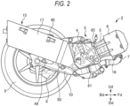
- FIG. 2 illustrates the engine unit 2, the rear wheel 9, the arm 10, and the exhaust device 15 as viewed from the right.
- the engine unit 2 includes an engine 3 that is an internal combustion engine which is a power source of the vehicle 1, and a transmission 8 configured to transmit power of the engine 3 to the rear wheel 9.
- the engine 3 is disposed forward of the rear wheel 9.
- the engine 3 includes a crankcase 4, a cylinder 5, and a cylinder head 6.
- the cylinder head 6 includes, at a lower portion, an exhaust port 7 through which exhaust gas from the inside of the cylinder 5 is exhausted to the exhaust device 15.
- the transmission 8 has a front portion coupled to a left portion of the crankcase 4.
- the transmission 8 has a rear portion disposed leftward of the rear wheel 9.
- the arm 10 is disposed rightward of the rear wheel 9.
- the arm 10 has a front end portion coupled to a right portion of the crankcase 4.
- the rear wheel 9 has a left end portion of an axle supported by the rear portion of the transmission 8.
- the rear wheel 9 has a right end portion of the axle supported by a rear end portion of the arm 10.
- the exhaust device 15 is disposed rightward of the engine 3 and the arm 10.
- FIG. 3 illustrates a muffler 17 in the exhaust device 15, as viewed from the left.
- FIG. 4 illustrates an interior of the muffler 17, and specifically illustrates a state in which a left wall plate 19A of an outer tube 19, an attachment member 71, an exhaust gas sensor 63, a left portion of a front lid 22, a left portion of a front inner tube 20, a left portion of a rear inner tube 21, and a left portion of glass wool 26 are removed from the muffler 17 in FIG. 3 .
- FIG. 5 illustrates a cross section of the muffler 17 cut along a cutting line V-V in FIG. 3 , as viewed from a rear upper side (upper right side in FIG. 3 ).
- FIG. 6 illustrates a state in which the exhaust gas sensor 63 is removed from the muffler 17 in FIG. 5 and the left wall plate 19A of the outer tube 19 and the attachment member 71 are separated from the muffler 17 in FIG. 5 .
- FIG. 7 illustrates the left wall plate 19A of the outer tube 19 of the muffler 17 and the attachment member 71 in an exploded state.
- the exhaust device 15 is a device configured to discharge exhaust gas from the engine 3 to the atmosphere.
- the exhaust device 15 includes an exhaust pipe 16, the muffler 17, an upstream catalyst 61, a downstream catalyst 62, the exhaust gas sensor 63, and the attachment member 71.
- the exhaust pipe 16 is a pipe configured to feed exhaust gas discharged from the exhaust port 7 of the engine 3 to the muffler 17. As illustrated in FIG. 2 , the exhaust pipe 16 has a front end portion connected to the exhaust port 7, and has a rear end portion connected to a front end portion (see FIG. 4 ) of an upstream pipe 34 provided in the muffler 17.
- the muffler 17 is a device configured to reduce exhaust noise.
- the muffler 17 is disposed rightward of the arm 10. As illustrated in FIG. 2 , the muffler 17 is fixed to the arm 10 by brackets 48, 49, and 50.
- the upstream catalyst 61 and the downstream catalyst 62 are devices configured to purify exhaust gas.
- the upstream catalyst 61 and the downstream catalyst 62 are, for example, two-way catalysts. As illustrated in FIG. 2 , the upstream catalyst 61 is disposed in the exhaust pipe 16. As illustrated in FIG. 4 , the downstream catalyst 62 is disposed in the muffler 17.
- the exhaust gas sensor 63 is a sensor configured to detect a state of exhaust gas flowed through the downstream catalyst 62.
- the deterioration of the downstream catalyst 62 can be determined by detecting the state of the exhaust gas flowed through the downstream catalyst 62.
- the exhaust gas sensor 63 is attached to a rear left portion of the muffler 17.
- the exhaust gas sensor 63 is, for example, a zirconia oxygen sensor.
- the exhaust gas sensor 63 is configured to detect an oxygen concentration of the exhaust gas flowed through the downstream catalyst 62.
- the exhaust gas sensor 63 includes, inside one end portion, a sensor element 64 made of zirconia.
- the exhaust gas sensor 63 has the other end portion connected to a cable 65. As illustrated in FIG. 3 , the cable 65 extends forward from the other end portion of the exhaust gas sensor 63 through between the arm 10 and the muffler 17. The cable 65 is supported, by clamps 66, on the bracket 48 that fixes the muffler 17 to the arm 10.
- the cable 65 is specifically a harness cable.
- the cable 65 is a bundle of a signal cable configured to transmit a detection signal obtained from the sensor element 64, a power cable configured to supply power to a heater (not illustrated) provided in the exhaust gas sensor 63 to heat the sensor element 64, and the like.
- the signal cable has one end portion connected to the sensor element 64.
- the signal cable has the other end portion connected to, for example, an electronic control unit (ECU) provided in the vehicle 1.
- ECU electronice control unit
- the power cable has one end portion connected to the heater.
- the power cable has the other end portion connected to a power supply device provided in the vehicle 1.
- the attachment member 71 attaches the exhaust gas sensor 63 to the muffler 17.
- the attachment member 71 is attached to the left wall plate 19A of the outer tube 19 of the muffler 17.
- the exhaust gas sensor 63 is fixed to the attachment member 71.
- the muffler 17 has an outer wall 18 that defines an outer shell of the muffler 17.
- the outer wall 18 includes the outer tube 19, the front inner tube 20, the rear inner tube 21, the front lid 22, a rear lid 23, a support member 24, a coupling member 25, and the glass wool 26.
- the outer tube 19 has a tubular shape extending in a front-rear direction. Strictly speaking, the entire muffler 17 is attached to the vehicle 1 in an inclined posture in which a rear end of the muffler 17 is located above a front end of the muffler 17.
- the outer tube 19 is formed in a tubular shape extending in the front-rear direction while being inclined such that a rear end of the outer tube 19 is located above a front end of the outer tube 19.
- the outer tube 19 has an elliptical cross-sectional shape in which a vertical dimension is larger than a horizontal dimension. As illustrated in FIG. 5 , the outer tube 19 includes the left wall plate 19A and a right wall plate 19B.
- the left wall plate 19A and the right wall plate 19B are each formed by pressing and bending a flat plate made of a metal material such as stainless steel.
- the outer tube 19 is formed in a tubular shape by joining respective edge portions of the left wall plate 19A and the right wall plate 19B to each other by welding, for example.
- a front portion of a trunk portion of the outer wall 18 has a double tubular structure including the outer tube 19 and the front inner tube 20, and a rear portion of the trunk portion of the outer wall 18 has a double tubular structure including the outer tube 19 and the rear inner tube 21.
- Each of the front inner tube 20 and the rear inner tube 21 is made of a metal material, and is formed into a tubular shape having an elliptical cross-sectional shape.
- the front inner tube 20 is disposed on an inner peripheral side of a front portion of the outer tube 19.
- the rear inner tube 21 is disposed on an inner peripheral side of a rear portion of the outer tube 19.
- the front lid 22 is attached to front end portions of the outer tube 19 and the front inner tube 20.
- the front lid 22 blocks front openings of the outer tube 19 and the front inner tube 20.
- the front lid 22 has an insertion hole in a front end portion. A front end portion of the upstream pipe 34 is inserted into the insertion hole.
- the rear lid 23 is attached to rear end portions of the outer tube 19 and the rear inner tube 21.
- the rear lid 23 blocks rear openings of the outer tube 19 and the rear inner tube 21.
- the rear lid 23 has an insertion hole in a rear end portion. A rear end portion of a tail pipe 41 is inserted into the insertion hole.
- the support member 24 is a member that supports, on an inner peripheral side of the outer tube 19, a rear end portion of the front inner tube 20 and a front end portion of the rear inner tube 21.
- the coupling member 25 is a member that couples a rear end portion of the front lid 22 and the front end portions of the outer tube 19 and the front inner tube 20 to each other.
- the support member 24 and the coupling member 25 both have an annular shape.
- the rear end portions of the outer tube 19 and the rear inner tube 21 are coupled to an outer peripheral portion of the rear lid 23.
- the glass wool 26 is provided between the outer tube 19 and the front inner tube 20 and between the outer tube 19 and the rear inner tube 21.
- the glass wool 26 is a heat insulating material and a sound deadening material.
- the glass wool 26 has a heat insulating function of preventing heat of exhaust gas fed into the muffler 17 from being transferred to the outer tube 19, and a mute function of enhancing a deadening effect of the muffler 17.
- the muffler 17 includes two partition walls 27 and 28. With the partition walls 27 and 28, a first expansion chamber 31 in a rear portion, a second expansion chamber 32 in an intermediate portion in the front-rear direction, and a third expansion chamber 33 in a front portion are defined in the muffler 17.
- the muffler 17 includes the upstream pipe 34, the downstream catalyst 62, a downstream pipe 35, a first communication pipe 39, a second communication pipe 40, and the tail pipe 41.
- the upstream pipe 34 is a pipe that connects the exhaust pipe 16 and the downstream catalyst 62 in the muffler 17.
- the upstream pipe 34 extends in the front-rear direction substantially parallel to an extending direction of the outer tube 19.
- the upstream pipe 34 has a front end portion disposed outside the muffler 17 through the insertion hole provided in the front end portion of the front lid 22.
- the front end portion of the upstream pipe 34 is connected to the rear end portion of the exhaust pipe 16.
- the upstream pipe 34 except the front end portion passes through the third expansion chamber 33 and then reaches the second expansion chamber 32 through an insertion hole for the upstream pipe 34 provided in the partition wall 28.
- the upstream pipe 34 has a rear end portion connected to a front end portion (upstream end portion) of the downstream catalyst 62, in the second expansion chamber 32.
- the downstream catalyst 62 extends in the front-rear direction in parallel with the extending direction of the outer tube 19.
- the downstream catalyst 62 is disposed in a lower position of a substantially middle portion of the muffler 17 in the front-rear direction.
- the downstream catalyst 62 has a front portion (upstream portion) disposed in the second expansion chamber 32, an intermediate portion in the front-rear direction that passes through an insertion hole for the downstream catalyst 62 provided in the partition wall 28, and a rear portion (downstream portion) disposed in the first expansion chamber 31.
- the downstream catalyst 62 is disposed at the center of the muffler 17 in a left-right direction (width direction).
- the downstream pipe 35 is provided downstream of the downstream catalyst 62 in the muffler 17.
- the downstream pipe 35 is a pipe through which the exhaust gas flowed through the downstream catalyst 62 flows. As illustrated in FIG. 4 , the downstream pipe 35 is disposed rearward of the downstream catalyst 62, in the first expansion chamber 31.
- the downstream pipe 35 extends in the front-rear direction parallel to the extending direction of the outer tube 19.
- the downstream pipe 35 has a front end portion connected to a rear end portion (downstream end portion) of the downstream catalyst 62.
- the downstream pipe 35 further has a rear end portion opened into the first expansion chamber 31.
- the front end portion of the downstream pipe 35 has an outer diameter substantially equal to an outer diameter of the downstream catalyst 62.
- the outer diameter of the front end portion of the downstream pipe 35 is slightly larger than the outer diameter of the downstream catalyst 62 since the rear end portion of the downstream catalyst 62 is inserted into the front end portion of the downstream pipe 35.
- the downstream pipe 35 decreases in diameter rearward from a front portion.
- the downstream pipe 35 has an outer diameter at a rear portion that is smaller than the outer diameter of the downstream catalyst 62.
- the rear portion of the downstream pipe 35 extends while maintaining a constant diameter.
- the downstream pipe 35 is disposed at the center of the muffler 17 in the left-right direction similarly to the downstream catalyst 62.
- the front portion of the downstream pipe 35 decreases in diameter such that the center of the front portion gradually displaces leftward.
- the downstream pipe 35 has a structure that is formed by joining a left plate piece 35A and a right plate piece 35B, which are curved metal plates, to each other by welding, for example.
- the downstream pipe is a specific example of a "pipe".
- the downstream pipe 35 has a sensor insertion hole 38 in a rear left portion.
- the downstream pipe 35 includes, on a portion slightly above the rear left portion, a projecting portion 36 projecting leftward while being slightly inclined upward relative to a horizontal direction.
- the projecting portion 36 includes, at a projecting end, a flat plate portion 37 having a flat surface extending in a direction orthogonal to a projecting direction of the projecting portion 36. As illustrated in FIG.
- the flat plate portion 37 is in a vicinity of a right surface of a bottom portion 75C of a second tubular member 75 of the attachment member 71, and the flat surface of the flat plate portion 37 is parallel to the right surface of the bottom portion 75C of the second tubular member 75 of the attachment member 71.
- the sensor insertion hole 38 is formed in the flat plate portion 37.
- the sensor insertion hole 38 is a hole through which the one end portion of the exhaust gas sensor 63 is inserted into the downstream pipe 35.
- the sensor insertion hole 38 penetrates a peripheral wall of the downstream pipe 35, specifically, the flat plate portion 37.
- the first communication pipe 39 extends in the front-rear direction parallel to the extending direction of the outer tube 19.
- the first communication pipe 39 has a rear end portion disposed in the first expansion chamber 31 and opened in the first expansion chamber 31.
- the first communication pipe 39 extends from the inside of the first expansion chamber 31 to the inside of the second expansion chamber 32 through an insertion hole for the first communication pipe 39 provided in the partition wall 27, and has a front end portion opened in the second expansion chamber 32.
- the first expansion chamber 31 communicates with the second expansion chamber 32 via the first communication pipe 39.
- the second communication pipe 40 extends in the front-rear direction parallel to the extending direction of the outer tube 19.
- the second communication pipe 40 has a rear end portion disposed in the second expansion chamber 32 and opened in the second expansion chamber 32.
- the second communication pipe 40 extends from the inside of the second expansion chamber 32 to the inside of the third expansion chamber 33 through an insertion hole for the second communication pipe 40 provided in the partition wall 28, and has a front end portion opened in the third expansion chamber 33.
- the second expansion chamber 32 communicates with the third expansion chamber 33 via the second communication pipe 40.
- the tail pipe 41 extends in the front-rear direction parallel to the extending direction of the outer tube 19.
- the tail pipe 41 has a front end portion disposed in the third expansion chamber 33 and opened in the third expansion chamber 33.
- the tail pipe 41 passes through an insertion hole for the tail pipe 41 provided in the partition wall 28, then through the second expansion chamber 32, then through an insertion hole for the tail pipe 41 provided in the partition wall 27, then through the first expansion chamber 31, then through the insertion hole provided in the rear lid 23, and extends to the outside of the muffler 17.
- the tail pipe 41 has a rear end portion opened rearward outside the muffler 17.
- Exhaust gas discharged from the exhaust port 7 of the engine 3 flows into the exhaust pipe 16, through the upstream catalyst 61, then through the upstream pipe 34 of the muffler 17, then through the downstream catalyst 62, then through the downstream pipe 35, and flows into the first expansion chamber 31 from the opening at the rear end portion of the downstream pipe 35.
- the exhaust gas flowed into the first expansion chamber 31 flows through the first communication pipe 39 and flows into the second expansion chamber 32.
- the exhaust gas flowed into the second expansion chamber 32 flows through the second communication pipe 40 and flows into the third expansion chamber 33.
- the exhaust gas flowed into the third expansion chamber 33 flows through the tail pipe 41 and is discharged into the atmosphere from an opening on a rear end side of the tail pipe 41.
- the muffler 17 has, in a left portion of the outer wall 18, a through hole penetrating the left portion of the outer wall 18.
- the left wall plate 19A of the outer tube 19 has a hole 45 penetrating the left wall plate 19A.
- the hole 45 is disposed in a substantially middle portion of a rear portion of the left wall plate 19A in the up-down direction.
- the rear inner tube 21 is provided with, in a portion of a peripheral wall thereof that corresponds to the hole 45 provided in the left wall plate 19A of the outer tube 19, a hole 46 penetrating the peripheral wall of the rear inner tube 21.
- the glass wool 26 disposed between the outer tube 19 and the rear inner tube 21 is provided with, in a portion corresponding to the hole 45 provided in the left wall plate 19A of the outer tube 19, a hole 47 penetrating the glass wool 26.
- the muffler 17 is formed with, in the left portion of the outer wall 18, a through hole including the hole 45 of the left wall plate 19A of the outer tube 19, the hole 46 of the rear inner tube 21, and the hole 47 of the glass wool 26, and penetrates the left portion of the outer wall 18.
- a diameter of the through hole, that is, a diameter of each of the holes 45,46, 47 is set to be a value larger than a maximum outer diameter of the exhaust gas sensor 63.
- the attachment member 71 is a member separate from the muffler 17.
- the attachment member 71 has a bottomed tubular shape, specifically, a bottomed cylindrical shape. More specifically, as illustrated in FIG. 6 , the attachment member 71 has a cup shape.
- the attachment member 71 is attached to a peripheral edge portion of the through hole provided in the left portion of the outer wall 18 of the muffler 17.
- the attachment member 71 is attached to the outer wall 18 such that the attachment member 71 enters the muffler 17, an opening side of the attachment member 71 faces the outside of the muffler 17, and a bottom side of the attachment member 71 faces the inside of the muffler 17.
- the attachment member 71 extends rightward from the left portion of the outer wall 18 of the muffler 17 while being slightly inclined downward toward a portion (the flat plate portion 37) slightly above the left portion of the downstream pipe 35.
- a bottom portion of the attachment member 71 is in a vicinity of the flat plate portion 37 of the downstream pipe 35 but is not in contact therewith.
- the attachment member 71 gradually decreases in diameter from the left portion of the outer wall 18 of the muffler 17 toward the flat plate portion 37 of the downstream pipe 35.
- a lower portion 72 of a peripheral wall portion of the attachment member 71 is inclined such that the opening side of the attachment member 71 is located below the bottom side of the attachment member 71.
- Each of an opening and the bottom portion of the attachment member 71 has an inner diameter set to be a value larger than the maximum outer diameter of the exhaust gas sensor 63.
- the attachment member 71 includes a first tubular member 73, the second tubular member 75, and glass wool 77.
- Each of the first tubular member 73 and the second tubular member 75 is made of a metal material such as stainless steel and has a bottomed tubular shape, specifically, a bottomed cylindrical shape, more specifically, a cup shape.
- the second tubular member 75 is attached to the first tubular member 73 such that the second tubular member 75 covers a surface of the first tubular member 73 that faces the inside of the muffler 17.
- a peripheral edge portion 75A of an opening of the second tubular member 75 is joined to a peripheral edge portion 73A of an opening of the first tubular member 73 over an entire periphery by, for example, welding.
- a joining portion between the first tubular member 73 and the second tubular member 75 is only the peripheral edge portion 75A of the opening of the second tubular member 75 and the peripheral edge portion 73A of the opening of the first tubular member 73.
- a surface of the peripheral edge portion 75A of the opening of the second tubular member 75 that faces the outside of the muffler 17 is in contact with a surface of the peripheral edge portion 73A of the opening of the first tubular member 73 that faces the inside of the muffler 17 over an entire periphery.
- a surface of the bottom portion 75C of the second tubular member 75 that faces the outside of the muffler 17 is in contact with a surface of a bottom portion 73C of the first tubular member 73 that faces the inside of the muffler 17.
- a peripheral wall portion 73B of the first tubular member 73 and a peripheral wall portion 75B of the second tubular member 75 are separated from each other.
- the peripheral edge portion 73A of the opening of the first tubular member 73 is joined to a peripheral edge portion of the hole 45 of the left wall plate 19A of the outer tube 19 by, for example, welding, over an entire periphery. Accordingly, the attachment member 71 is attached to the peripheral edge portion of the through hole of the outer wall 18. Further, the surface of the peripheral edge portion 73A of the opening of the first tubular member 73 that faces the outside of the muffler 17 is in contact with a surface of the left wall plate 19A of the outer tube 19 that faces the inside of the muffler 17 (a right surface of the left wall plate 19A) over an entire periphery.
- the glass wool 77 is provided between the peripheral wall portion 73B of the first tubular member 73 and the peripheral wall portion 75B of the second tubular member 75.
- the glass wool 77 is a heat insulating material and a sound deadening material.
- the glass wool 77 has a heat insulating function of preventing heat of exhaust gas fed into the muffler 17 from being transferred to the first tubular member 73 and a mute function of enhancing a deadening effect of the muffler 17.
- the first tubular member 73 has, at the center of the bottom portion 73C, a bottom hole 74 penetrating the bottom portion 73C.
- the second tubular member 75 has, at the center of the bottom portion 75C, a bottom hole 76 penetrating the bottom portion 75C.
- positions of the bottom hole 74 and the bottom hole 76 correspond to each other.
- the positions of the bottom hole 74 and the bottom hole 76 correspond to a position of the sensor insertion hole 38 of the downstream pipe 35.
- the attachment member 71 includes a boss portion 78.
- the boss portion 78 is a member configured to fix the exhaust gas sensor 63 to the attachment member 71.
- the boss portion 78 has, for example, a cylindrical shape, and the center of the boss portion 78 is a fixing hole 79 for fixing the exhaust gas sensor 63.
- the fixing hole 79 is formed with an internal thread on an inner peripheral surface. As illustrated in FIG. 5 , the exhaust gas sensor 63 is inserted into and fastened to the fixing hole 79, and fixed to the boss portion 78.
- FIG. 8 illustrates the bottom portion of the attachment member 71, the boss portion 78, and the sensor insertion hole 38 of the downstream pipe 35 in an enlarged manner.
- the boss portion 78 is attached to the bottom side of the attachment member 71.
- the boss portion 78 is joined to the peripheral edge portion of the bottom hole 74 of the first tubular member 73 by, for example, welding.
- an outer peripheral surface of the boss portion 78 is welded to the peripheral edge portion of the bottom hole 74 over an entire periphery.
- a joining portion between the boss portion 78 and the attachment member 71 is only the peripheral edge portion of the bottom hole 74 of the first tubular member 73.
- the boss portion 78 is inserted into the bottom hole 76 of the second tubular member 75 in a non-joined state.
- the bottom portion 73C of the first tubular member 73 and the bottom portion 75C of the second tubular member 75 are in a vicinity of the flat plate portion 37 of the downstream pipe 35.
- the boss portion 78 projects from the bottom portion 73C of the first tubular member 73 toward the flat plate portion 37 of the downstream pipe 35.
- a projecting end portion of the boss portion 78 is inserted into the sensor insertion hole 38 in a state of not being joined to the peripheral edge portion of the sensor insertion hole 38.
- the boss portion 78 has an outer diameter D 1 smaller than a diameter D2 of the sensor insertion hole 38.
- the projecting end portion of the boss portion 78 is inserted into the sensor insertion hole 38 in a state in which an entire periphery thereof is separated from the peripheral edge portion of the sensor insertion hole 38.
- a size of a gap between the projecting end portion of the boss portion 78 and the peripheral edge portion of the sensor insertion hole 38 is set to be a fairly small value (for example, 6 mm or less) such that exhaust gas can be sufficiently prevented from flowing through the gap during operation of the engine 3 (when the exhaust gas is fed from the engine 3 into the muffler 17).
- the exhaust gas sensor 63 is inserted into the through hole (the holes 45,46, 47) of the outer wall 18, and is disposed inside the attachment member 71.
- the one end portion of the exhaust gas sensor 63 is inserted into the bottom holes 74 and 76 (the fixing hole 79) and the sensor insertion hole 38. Accordingly, a portion of the sensor element 64 of the exhaust gas sensor 63 is inserted into the downstream pipe 35.
- the other end portion of the exhaust gas sensor 63 is disposed outside the muffler 17, and the cable 65 connected to the other end portion of the exhaust gas sensor 63 is located outside the muffler 17. In this state, the exhaust gas sensor 63 is fixed to the boss portion 78 provided on the attachment member 71.
- the bottom hole 74 (the fixing hole 79) is blocked. Accordingly, the through hole of the outer wall 18 is more tightly blocked by the attachment member 71 attached to the peripheral edge portion thereof and the exhaust gas sensor 63 fixed to the attachment member 71.
- Exhaust gas flowed through the downstream catalyst 62 flows through the downstream pipe 35.
- the exhaust gas sensor 63 is configured to detect an oxygen concentration of the exhaust gas flowing through the downstream pipe 35.
- a detection signal indicating the oxygen concentration detected by the exhaust gas sensor 63 is output to an electronic control unit via the cable 65 (signal cable).
- the electronic control unit determines, for example, deterioration of the downstream catalyst 62 based on the detection signal.
- the exhaust device 15 has a configuration in which the outer wall 18 of the muffler 17 is provided with a through hole (the holes 45, 46, and 47), the attachment member 71, which is a bottomed tubular member separate from the muffler 17, is attached to the peripheral edge portion of the through hole, and the exhaust gas sensor 63 is disposed inside the attachment member 71 via the through hole of the outer wall 18 and is fixed to the attachment member 71 in a state in which the one end portion of the exhaust gas sensor 63 is inserted into the bottom holes 74 and 76 (the fixing hole 79) and the sensor insertion hole 38.
- the attachment member 71 which is a bottomed tubular member separate from the muffler 17 is attached to the peripheral edge portion of the through hole
- the exhaust gas sensor 63 is disposed inside the attachment member 71 via the through hole of the outer wall 18 and is fixed to the attachment member 71 in a state in which the one end portion of the exhaust gas sensor 63 is inserted into the bottom holes 74 and 76 (the
- the exhaust gas sensor 63 can be easily attached to the muffler 17 in a state in which the sensor element 64 provided at the one end portion of the exhaust gas sensor 63 is disposed inside the downstream pipe 35 and the other end portion of the exhaust gas sensor 63 and the cable 65 connected to the other end portion are disposed outside the muffler 17.
- the structure in which a portion of the outer wall 18 of the muffler 17 is recessed toward the inside of the muffler 17 can be formed by a method of forming a recess in the outer wall 18 by pressing the outer wall 18 of the muffler 17 or a method of attaching the attachment member 71 to the peripheral edge portion of the through hole of the outer wall 18 of the muffler 17.
- a portion of the outer wall 18 of the muffler 17 is recessed toward the inside of the muffler 17 is formed by the method of forming a recess in the outer wall 18 by pressing the outer wall 18 of the muffler 17, it is difficult to form a recess having a large depth and large strength.
- the attachment member 71 is a member separate from the muffler 17 in a stage before the attachment member 71 is attached to the peripheral edge portion of the through hole of the outer wall 18 of the muffler 17.
- the pressing for forming the left wall plate 19A of the outer tube 19 on the outer wall 18 of the silencer 17 and the pressing for forming the first tubular member 73 and the second tubular member 75 on the attachment member 71 can be separately performed.
- the first tubular member 73 and the second tubular member 75 of the attachment member 71 are formed by drawing or the like, it is easy to increase an axial dimension of the attachment member 71, that is, the depth of the recess, and it is easy to increase the strength of the attachment member 71, that is, the strength of the recess, as compared with when the recess is formed by protrusion or the like in the left wall plate 19A of the outer tube 19 of the outer wall 18 of the muffler 17.
- the attachment member 71 having an axial dimension equivalent to the distance can be easily manufactured.
- the exhaust gas sensor 63 can be easily attached to the muffler 17 in a state in which the sensor element 64 provided at the one end portion of the exhaust gas sensor 63 is disposed inside the downstream pipe 35 and the other end portion of the exhaust gas sensor 63 and the cable 65 connected to the other end portion are disposed outside the muffler 17.
- the through hole (the holes 45, 46, and 47) of the outer wall 18 of the muffler 17 is provided in the left portion of the outer wall 18, the sensor insertion hole 38 is provided in the left portion of the downstream pipe 35 (strictly, a portion slightly above the rear left portion of the downstream pipe 35), the attachment member 71 extends rightward and gradually decreases in diameter from the left portion of the outer wall 18 of the muffler 17 toward the left portion of the downstream pipe 35.
- the lower portion 72 of the peripheral wall portion of the attachment member 71 is inclined such that the opening side of the attachment member 71 is located below the bottom side of the attachment member 71.
- the downstream catalyst 62 is disposed at the center of the muffler 17 in the left-right direction.
- the downstream catalyst 62 can be far apart from the outer wall 18 of the muffler 17, and heat from the downstream catalyst 62 can be prevented from being transferred to the outer wall 18 of the muffler 17. Accordingly, it is possible to prevent heat damage to other components arranged around the muffler 17.
- the downstream catalyst 62 is disposed in a vicinity of the center in the muffler 17, the distance between the outer peripheral surface of the downstream pipe 35 connected to a downstream end portion of the downstream catalyst 62 and the outer surface of the outer wall 18 of the muffler 17 is fairly long.
- the exhaust gas sensor 63 that detects a state of the exhaust gas flowing through the downstream pipe 35 can be easily attached to the muffler 17.
- the projecting end portion of the boss portion 78 provided at the attachment member 71 is inserted into the sensor insertion hole 38 in a state of not being joined to the peripheral edge portion of the sensor insertion hole 38 of the downstream pipe 35, and the projecting end portion of the boss portion 78 is inserted into the sensor insertion hole 38 in a state of being separated from the peripheral edge portion of the sensor insertion hole 38.
- the boss portion 78 and the downstream pipe 35 are pulled, and stress is applied to the boss portion 78, the attachment member 71, the downstream pipe 35, and the like.
- the projecting end portion of the boss portion 78 is not joined to and separated from the peripheral edge portion of the sensor insertion hole 38 of the downstream pipe 35.
- the boss portion 78 can be displaced relative to the downstream pipe 35. Accordingly, stress can be prevented from being applied to the boss portion 78, the attachment member 71, the downstream pipe 35, and the like.
- the exhaust device 15 in the present embodiment it is possible to prevent the boss portion 78, the attachment member 71, the downstream pipe 35, and the like from being damaged when the outer wall 18 of the muffler 17, the attachment member 71, and the like are deformed by the heat of the exhaust gas.
- the glass wool 77 having a heat insulating function and a deadening function is provided between the peripheral wall portion 73B of the first tubular member 73 and the peripheral wall portion 75B of the second tubular member 75.
- the joining portion between the boss portion 78 and the attachment member 71 is only the peripheral edge portion of the bottom hole 74 of the first tubular member 73, and the joining portion between the first tubular member 73 and the second tubular member 75 is only the peripheral edge portion 73A of the opening of the first tubular member 73 and the peripheral edge portion 75A of the opening of the second tubular member 75.
- the projecting end portion of the boss portion 78 is inserted into the sensor insertion hole 38 in a state of being separated from the peripheral edge portion of the sensor insertion hole 38.
- the present invention is not limited thereto, and the projecting end portion of the boss portion may be in light contact with the peripheral edge portion of the sensor insertion hole.
- the projecting end portion of the boss portion may be in light contact with the peripheral edge portion of the sensor insertion hole.
- a boss portion 91 may be provided with a tapered portion 91A at a projecting end portion, a peripheral edge portion 93 of a sensor insertion hole 92 may be bent toward the inside of the downstream pipe 35, and an outer peripheral surface of the tapered portion 91A of the boss portion 91 may be in light contact with the peripheral edge portion 93 of the sensor insertion hole 92.
- the glass wool 77 is provided between the peripheral wall 73B of the first tubular member 73 and the peripheral wall 75B of the second tubular member 75 in the attachment member 71.
- a space may be defined between the peripheral wall portion 73B of the first tubular member 73 and the peripheral wall portion 75B of the second tubular member 75 without providing anything.
- a heat insulating material or a sound deadening material other than glass wool may be provided between the peripheral wall portion 73B of the first tubular member 73 and the peripheral wall portion 75B of the second tubular member 75, between the outer tube 19 and the front inner tube 20, or between the outer tube 19 and the rear inner tube 21.
- the exhaust device 15 is disposed on a right side of a vehicle.
- the present invention is also applicable to an exhaust device disposed on a left side of a vehicle.
- arrangements and orientations of components of the exhaust device 15 are left-right reversed.
- a downstream catalyst may be disposed in the muffler in a position deviated from the center of the muffler in the left-right direction (width direction).
- the present invention can be further applied to various types of motorcycles in addition to scooters, and can be applied to various types of vehicles in addition to motorcycles.
Landscapes
- Engineering & Computer Science (AREA)
- Chemical & Material Sciences (AREA)
- Combustion & Propulsion (AREA)
- Mechanical Engineering (AREA)
- General Engineering & Computer Science (AREA)
- Analytical Chemistry (AREA)
- Exhaust Silencers (AREA)
- Exhaust Gas After Treatment (AREA)
Abstract
Description
- The present invention relates to an exhaust device for discharging exhaust gas from an internal combustion engine of a vehicle.
- In a vehicle using an internal combustion engine as a power source, such as a four-wheeled vehicle or a motorcycle, a catalyst may be provided in a muffler. To detect a state of exhaust gas flowed through the catalyst, an exhaust gas sensor may be attached to the muffler.
JP2017-227157A - An exhaust gas sensor detects an oxygen concentration in exhaust gas. A zirconia oxygen sensor using zirconia as a sensor element is usually used as an exhaust gas sensor provided in a vehicle.
- An operation principle of the zirconia oxygen sensor is as follows. When one side of the sensor element formed of zirconia is exposed to exhaust gas and a reference gas (for example, air) is supplied to the other side of the sensor element, an electromotive force is generated in the sensor element due to an oxygen concentration difference between the reference gas and the exhaust gas. An oxygen concentration in the exhaust gas is detected based on the electromotive force.
- A zirconia oxygen sensor provided in a vehicle is provided with a sensor element at one end portion in an axial direction of a tubular casing, and the other end portion of the casing is connected to a cable. The zirconia oxygen sensor is further provided with, at the other end portion of the casing, an inlet for introducing air to be supplied to the sensor element into the casing. When detecting an oxygen concentration in exhaust gas flowed through a catalyst, the oxygen sensor is attached to a muffler such that the sensor element is disposed, for example, inside a pipe (hereinafter referred to as a "catalyst downstream pipe") connected downstream of the catalyst in the muffler and that the cable and the inlet are disposed outside the muffler. Specifically, the catalyst downstream pipe is provided with a through hole in a peripheral wall, the muffler is provided with a through hole in an outer wall in a portion corresponding to the through hole of the catalyst downstream pipe, and the sensor element provided at the one end portion of the oxygen sensor is inserted into the two through holes. In this state, the cable and the inlet are disposed outside the muffler. In this state, the casing of the oxygen sensor is fixed to the outer wall of the muffler.
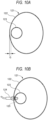
- As illustrated in
FIG. 10A , in a case where a catalystdownstream pipe 123 is in a vicinity of anouter wall 122 of amuffler 121 and a distance G between an outer surface of theouter wall 122 of themuffler 121 and an outer peripheral surface of the catalystdownstream pipe 123 is short, as illustrated inFIG. 10B , the catalystdownstream pipe 123 is provided with a through hole in a peripheral wall, themuffler 121 is provided with a through hole in theouter wall 122 in a portion corresponding to the through hole of the catalystdownstream pipe 123, and anexhaust gas sensor 124 can be fixed to theouter wall 122 of themuffler 121 in a state in which asensor element 125 provided at one end portion of theexhaust gas sensor 124 is inserted into the two through holes. In this manner, when the distance between the outer surface of the outer wall of the muffler and the outer peripheral surface of the catalyst downstream pipe is short, the exhaust gas sensor can be attached to the muffler in a state in which the sensor element provided at the one end portion of the exhaust gas sensor is disposed inside the catalyst downstream pipe and a cable or the like provided at the other end portion of the exhaust gas sensor is disposed outside the muffler. - As illustrated in
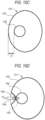
FIG. 10C , even when the catalystdownstream pipe 123 is apart from theouter wall 122 of themuffler 121 by a certain distance and the distance G between the outer surface of theouter wall 122 of themuffler 121 and the outer peripheral surface of the catalystdownstream pipe 123 is relatively long, as illustrated inFIG. 10D , the catalystdownstream pipe 123 is provided with a through hole in the peripheral wall, themuffler 121 is formed with arecess 126 in theouter wall 122 in a portion corresponding to the through hole of the catalystdownstream pipe 123 by pressing theouter wall 122 of themuffler 121, therecess 126 is provided with a through hole in a bottom portion, and theexhaust gas sensor 124 can be fixed to theouter wall 122 of themuffler 121 in a state in which thesensor element 125 provided at the one end portion of theexhaust gas sensor 124 is inserted into the through hole provided in the peripheral wall of the catalystdownstream pipe 123 and the through hole provided in the bottom portion of therecess 126. In this manner, even when the distance between the outer surface of the outer wall of the muffler and the outer peripheral surface of the catalyst downstream pipe is relatively long, by forming the recess by pressing the outer wall of the muffler, the exhaust gas sensor can be attached to the muffler in a state in which the sensor element provided at the one end portion of the exhaust gas sensor is disposed inside the catalyst downstream pipe and the cable or the like provided at the other end portion of the exhaust gas sensor is disposed outside the muffler. - However, for example, as illustrated in
FIG. 10E , when the catalystdownstream pipe 123 is far apart from theouter wall 122 of themuffler 121 and the distance G between the outer surface of theouter wall 122 of themuffler 121 and the outer peripheral surface of the catalystdownstream pipe 123 is fairly long, by the method of forming the recess by pressing the outer wall of the muffler, the exhaust gas sensor is difficult to be attached to the muffler in a state in which the sensor element provided at the one end portion of the exhaust gas sensor is disposed inside the catalyst downstream pipe and the cable or the like provided at the other end portion of the exhaust gas sensor is disposed outside the muffler. - That is, when the distance between the outer surface of the outer wall of the muffler and the outer peripheral surface of the catalyst downstream pipe is fairly long, it is necessary to increase a depth of the recess formed in the outer wall of the muffler so that the sensor element provided at the one end portion of the exhaust gas sensor can be disposed inside the catalyst downstream pipe. It is difficult to form a recess with a large depth in the outer wall of the muffler by pressing the outer wall of the muffler. For example, when a recess is formed by protrusion, a thickness of the recess at a peripheral wall portion or a bottom portion thereof may be excessively small and necessary strength of the recess may not be ensured. In addition, to form a recess having a large depth and large strength in the outer wall of the muffler by pressing, a processing technique of a high degree is necessary, which may increase the manufacturing cost of the muffler.
- Aspect of non-limiting embodiments of the present disclosure relates to provide an exhaust device in which an exhaust gas sensor that detects a state of exhaust gas flowed through a catalyst can be easily attached to a muffler even when a downstream side of the catalyst is far apart from an outer wall of the muffler in the muffler.
- Aspects of certain non-limiting embodiments of the present disclosure address the features discussed above and/or other features not described above. However, aspects of the non-limiting embodiments are not required to address the above features, and aspects of the non-limiting embodiments of the present disclosure may not address features described above.
- According to an aspect of the present disclosure, there is provided an exhaust device for discharging exhaust gas from an internal combustion engine of a vehicle, the exhaust device including:
- a muffler configured to reduce exhaust noise;
- a catalyst configured to purify exhaust gas, the catalyst being provided in the muffler;
- a pipe in which exhaust gas flowed through the catalyst flows, the pipe being provided downstream of the catalyst in the muffler;
- an exhaust gas sensor configured to detect a state of the exhaust gas flowed through the catalyst, the exhaust gas sensor including a sensor element at one end portion of the exhaust gas sensor; and
- an attachment member configured to attach the exhaust gas sensor to the muffler,
- in which the pipe has a sensor insertion hole through which the one end portion of the exhaust gas sensor is inserted into the pipe,
- the attachment member is a bottomed tubular member that is separate member from the muffler, is attached to a peripheral edge portion of a through hole penetrating an outer wall of the muffler, and extends from the outer wall of the muffler toward the pipe,
- the attachment member has, at a bottom portion of the attachment member, a bottom hole penetrating the bottom portion, and
- the exhaust gas sensor is disposed inside the attachment member via the through hole, and is fixed to the attachment member in a state where the one end portion of the exhaust gas sensor is inserted into the bottom hole and into the sensor insertion hole.
- Exemplary embodiment(s) of the present invention will be described in detail based on the following figures, wherein:
-
FIG. 1 is an external view illustrating a vehicle provided with an exhaust device according to an embodiment of the present invention; -
FIG. 2 illustrates an engine unit, a rear wheel, and the exhaust device according to the embodiment of the present invention; -
FIG. 3 illustrates a muffler in the exhaust device according to the embodiment of the present invention; -
FIG. 4 illustrates an interior of the muffler in the exhaust device according to the embodiment of the present invention; -
FIG. 5 is a cross-sectional view of the muffler taken along a cutting line V-V inFIG. 3 as viewed from a rear upper side; -
FIG. 6 illustrates a state in which an exhaust gas sensor is removed and a left wall plate of an outer tube of the muffler and an attachment member are separated from the muffler inFIG. 5 ; -
FIG. 7 illustrates the left wall plate of the outer tube of the muffler and the attachment member in an exploded state in the exhaust device according to the embodiment of the present invention; -
FIG. 8 is a cross-sectional view illustrating a bottom portion of the attachment member, a boss portion, and a sensor insertion hole of a downstream pipe in the exhaust device according to the embodiment of the present invention; -
FIG. 9 is a cross-sectional view illustrating a modification of the exhaust device according to the embodiment of the present invention; and -
FIGS. 10A to 10E relate to a method in the related art for attaching an exhaust gas sensor to a muffler to detect an oxygen concentration of exhaust gas flowed through a catalyst provided in the muffler. - An embodiment of the present invention describes an exhaust device for discharging exhaust gas from an internal combustion engine in a vehicle, and the exhaust device includes a muffler, a catalyst, a pipe, an exhaust gas sensor, and an attachment member. The muffler is a device configured to reduce exhaust noise. The catalyst is a device configured to purify exhaust gas, and is provided in the muffler. The pipe is a tubular member provided downstream of the catalyst in the muffler, and exhaust gas flowed through the catalyst flows through the pipe. The exhaust gas sensor is a sensor configured to detect a state of the exhaust gas flowed through the catalyst, and is provided with a sensor element at one end portion of the exhaust gas sensor. The pipe is provided with a sensor insertion hole through which the one end portion of the exhaust gas sensor is inserted into the pipe. The muffler is provided with, in an outer wall, a through hole penetrating the outer wall.
- The attachment member is a member configured to attach the exhaust gas sensor to the muffler. The attachment member is a bottomed tubular member separate from the muffler. The attachment member is attached to a peripheral edge portion of the through hole provided in the outer wall of the muffler. The attachment member extends from the outer wall of the muffler toward the pipe. The attachment member is provided with, in a bottom portion, a bottom hole penetrating the bottom portion. In the bottom portion of the attachment member, the bottom hole is disposed in a portion corresponding to the sensor insertion hole.
- The exhaust gas sensor is disposed inside the attachment member via the through hole provided in the outer wall of the muffler, and is fixed to the attachment member in a state in which the one end portion of the exhaust gas sensor is inserted into the bottom hole and the sensor insertion hole.
- By attaching the attachment member to the peripheral edge portion of the through hole provided in the outer wall of the muffler, the muffler is formed with substantially the same structure as that when a recess is formed in the outer wall by pressing the outer wall. In addition, by attaching the attachment member to the peripheral edge portion of the through hole provided in the outer wall of the muffler, it is easy to increase an axial dimension of the attachment member, that is, a depth of the recess, and it is easy to increase the strength of the attachment member, that is, the strength of the recess, as compared with a case where the recess is formed in the outer wall by pressing the outer wall of the muffler. Specifically, the attachment member is a member separate from the muffler in a stage before the attachment member is attached to the peripheral edge portion of the through hole of the outer wall of the muffler, and thus pressing for forming the outer wall of the muffler and pressing for forming the attachment member can be separately performed. When the attachment member is formed by drawing or the like, it is easy to increase the axial dimension of the attachment member, that is, the depth of the recess, and it is easy to increase the strength of the attachment member, that is, the strength of the recess, as compared with a case where the recess is formed in the outer wall of the muffler by protrusion or the like.
- Accordingly, even when a distance between an outer surface of the outer wall of the muffler and an outer peripheral surface of the pipe is fairly long, it is possible to easily manufacture an attachment member having an axial dimension equivalent to the distance. The attachment member is then attached to the peripheral edge portion of the through hole of the outer wall of the muffler, the exhaust gas sensor is inserted into the through hole of the outer wall of the muffler, disposed inside the attachment member attached to the outer wall, and fixed to the attachment member in a state in which the one end portion of the exhaust gas sensor is inserted into the bottom hole of the attachment member and the sensor insertion hole of the pipe. Accordingly, the exhaust gas sensor can be attached to the muffler in a state in which the sensor element provided at the one end portion of the exhaust gas sensor is disposed inside the pipe and the other end portion of the exhaust gas sensor is disposed outside the muffler.
- In this manner, according to the embodiment of the present invention, even when the pipe provided downstream of the catalyst in the muffler is far apart from the outer wall of the muffler, the exhaust gas sensor that detects a state of exhaust gas flowed through the catalyst can be easily attached to the muffler.
- An embodiment of the present invention will be described with reference to the drawings. In the description of the embodiment, when describing directions of up (Ud), down (Dd), front (Fd), rear (Bd), left (Ld), and right (Rd), the directions follow arrows drawn at corners in
FIGS. 1 to 9 . -
FIG. 1 illustrates avehicle 1 provided with an exhaust device according to the embodiment of the present invention as viewed from the right. In the present embodiment, an example of thevehicle 1 includes a straddle-type motorcycle, and specifically, a scooter. As illustrated inFIG. 1 , thevehicle 1 is provided with, at a rear lower portion, a unit swingtype engine unit 2, arear wheel 9, anarm 10 supporting therear wheel 9, and anexhaust device 15. -
FIG. 2 illustrates theengine unit 2, therear wheel 9, thearm 10, and theexhaust device 15 as viewed from the right. As illustrated inFIG. 2 , theengine unit 2 includes anengine 3 that is an internal combustion engine which is a power source of thevehicle 1, and atransmission 8 configured to transmit power of theengine 3 to therear wheel 9. - The
engine 3 is disposed forward of therear wheel 9. Theengine 3 includes acrankcase 4, acylinder 5, and acylinder head 6. Thecylinder head 6 includes, at a lower portion, anexhaust port 7 through which exhaust gas from the inside of thecylinder 5 is exhausted to theexhaust device 15. Thetransmission 8 has a front portion coupled to a left portion of thecrankcase 4. Thetransmission 8 has a rear portion disposed leftward of therear wheel 9. Thearm 10 is disposed rightward of therear wheel 9. Thearm 10 has a front end portion coupled to a right portion of thecrankcase 4. Therear wheel 9 has a left end portion of an axle supported by the rear portion of thetransmission 8. Therear wheel 9 has a right end portion of the axle supported by a rear end portion of thearm 10. Theexhaust device 15 is disposed rightward of theengine 3 and thearm 10. -
FIG. 3 illustrates amuffler 17 in theexhaust device 15, as viewed from the left.FIG. 4 illustrates an interior of themuffler 17, and specifically illustrates a state in which aleft wall plate 19A of anouter tube 19, anattachment member 71, anexhaust gas sensor 63, a left portion of afront lid 22, a left portion of a frontinner tube 20, a left portion of a rearinner tube 21, and a left portion ofglass wool 26 are removed from themuffler 17 inFIG. 3 .FIG. 5 illustrates a cross section of themuffler 17 cut along a cutting line V-V inFIG. 3 , as viewed from a rear upper side (upper right side inFIG. 3 ).FIG. 6 illustrates a state in which theexhaust gas sensor 63 is removed from themuffler 17 inFIG. 5 and theleft wall plate 19A of theouter tube 19 and theattachment member 71 are separated from themuffler 17 inFIG. 5 .FIG. 7 illustrates theleft wall plate 19A of theouter tube 19 of themuffler 17 and theattachment member 71 in an exploded state. - The
exhaust device 15 is a device configured to discharge exhaust gas from theengine 3 to the atmosphere. Theexhaust device 15 includes anexhaust pipe 16, themuffler 17, anupstream catalyst 61, adownstream catalyst 62, theexhaust gas sensor 63, and theattachment member 71. - The
exhaust pipe 16 is a pipe configured to feed exhaust gas discharged from theexhaust port 7 of theengine 3 to themuffler 17. As illustrated inFIG. 2 , theexhaust pipe 16 has a front end portion connected to theexhaust port 7, and has a rear end portion connected to a front end portion (seeFIG. 4 ) of anupstream pipe 34 provided in themuffler 17. - The
muffler 17 is a device configured to reduce exhaust noise. Themuffler 17 is disposed rightward of thearm 10. As illustrated inFIG. 2 , themuffler 17 is fixed to thearm 10 bybrackets - The
upstream catalyst 61 and thedownstream catalyst 62 are devices configured to purify exhaust gas. Theupstream catalyst 61 and thedownstream catalyst 62 are, for example, two-way catalysts. As illustrated inFIG. 2 , theupstream catalyst 61 is disposed in theexhaust pipe 16. As illustrated inFIG. 4 , thedownstream catalyst 62 is disposed in themuffler 17. - The
exhaust gas sensor 63 is a sensor configured to detect a state of exhaust gas flowed through thedownstream catalyst 62. The deterioration of thedownstream catalyst 62 can be determined by detecting the state of the exhaust gas flowed through thedownstream catalyst 62. As illustrated inFIG. 3 , theexhaust gas sensor 63 is attached to a rear left portion of themuffler 17. Theexhaust gas sensor 63 is, for example, a zirconia oxygen sensor. Theexhaust gas sensor 63 is configured to detect an oxygen concentration of the exhaust gas flowed through thedownstream catalyst 62. As illustrated inFIG. 5 , theexhaust gas sensor 63 includes, inside one end portion, asensor element 64 made of zirconia. - The
exhaust gas sensor 63 has the other end portion connected to acable 65. As illustrated inFIG. 3 , thecable 65 extends forward from the other end portion of theexhaust gas sensor 63 through between thearm 10 and themuffler 17. Thecable 65 is supported, byclamps 66, on thebracket 48 that fixes themuffler 17 to thearm 10. - The
cable 65 is specifically a harness cable. Thecable 65 is a bundle of a signal cable configured to transmit a detection signal obtained from thesensor element 64, a power cable configured to supply power to a heater (not illustrated) provided in theexhaust gas sensor 63 to heat thesensor element 64, and the like. The signal cable has one end portion connected to thesensor element 64. The signal cable has the other end portion connected to, for example, an electronic control unit (ECU) provided in thevehicle 1. The power cable has one end portion connected to the heater. The power cable has the other end portion connected to a power supply device provided in thevehicle 1. - As illustrated in
FIG. 3 , theattachment member 71 attaches theexhaust gas sensor 63 to themuffler 17. Theattachment member 71 is attached to theleft wall plate 19A of theouter tube 19 of themuffler 17. Theexhaust gas sensor 63 is fixed to theattachment member 71. - The
muffler 17 has anouter wall 18 that defines an outer shell of themuffler 17. Theouter wall 18 includes theouter tube 19, the frontinner tube 20, the rearinner tube 21, thefront lid 22, arear lid 23, asupport member 24, acoupling member 25, and theglass wool 26. - As illustrated in
FIGS. 3 to 5 , theouter tube 19 has a tubular shape extending in a front-rear direction. Strictly speaking, theentire muffler 17 is attached to thevehicle 1 in an inclined posture in which a rear end of themuffler 17 is located above a front end of themuffler 17. In view of this, theouter tube 19 is formed in a tubular shape extending in the front-rear direction while being inclined such that a rear end of theouter tube 19 is located above a front end of theouter tube 19. Theouter tube 19 has an elliptical cross-sectional shape in which a vertical dimension is larger than a horizontal dimension. As illustrated inFIG. 5 , theouter tube 19 includes theleft wall plate 19A and aright wall plate 19B. Theleft wall plate 19A and theright wall plate 19B are each formed by pressing and bending a flat plate made of a metal material such as stainless steel. Theouter tube 19 is formed in a tubular shape by joining respective edge portions of theleft wall plate 19A and theright wall plate 19B to each other by welding, for example. - As illustrated in
FIG. 4 , a front portion of a trunk portion of theouter wall 18 has a double tubular structure including theouter tube 19 and the frontinner tube 20, and a rear portion of the trunk portion of theouter wall 18 has a double tubular structure including theouter tube 19 and the rearinner tube 21. Each of the frontinner tube 20 and the rearinner tube 21 is made of a metal material, and is formed into a tubular shape having an elliptical cross-sectional shape. The frontinner tube 20 is disposed on an inner peripheral side of a front portion of theouter tube 19. The rearinner tube 21 is disposed on an inner peripheral side of a rear portion of theouter tube 19. - The
front lid 22 is attached to front end portions of theouter tube 19 and the frontinner tube 20. Thefront lid 22 blocks front openings of theouter tube 19 and the frontinner tube 20. Thefront lid 22 has an insertion hole in a front end portion. A front end portion of theupstream pipe 34 is inserted into the insertion hole. - The
rear lid 23 is attached to rear end portions of theouter tube 19 and the rearinner tube 21. Therear lid 23 blocks rear openings of theouter tube 19 and the rearinner tube 21. Therear lid 23 has an insertion hole in a rear end portion. A rear end portion of atail pipe 41 is inserted into the insertion hole. - The
support member 24 is a member that supports, on an inner peripheral side of theouter tube 19, a rear end portion of the frontinner tube 20 and a front end portion of the rearinner tube 21. Thecoupling member 25 is a member that couples a rear end portion of thefront lid 22 and the front end portions of theouter tube 19 and the frontinner tube 20 to each other. Thesupport member 24 and thecoupling member 25 both have an annular shape. The rear end portions of theouter tube 19 and the rearinner tube 21 are coupled to an outer peripheral portion of therear lid 23. - The
glass wool 26 is provided between theouter tube 19 and the frontinner tube 20 and between theouter tube 19 and the rearinner tube 21. Theglass wool 26 is a heat insulating material and a sound deadening material. Theglass wool 26 has a heat insulating function of preventing heat of exhaust gas fed into themuffler 17 from being transferred to theouter tube 19, and a mute function of enhancing a deadening effect of themuffler 17. - The
muffler 17 includes twopartition walls partition walls first expansion chamber 31 in a rear portion, asecond expansion chamber 32 in an intermediate portion in the front-rear direction, and athird expansion chamber 33 in a front portion are defined in themuffler 17. - As illustrated in
FIG. 4 , themuffler 17 includes theupstream pipe 34, thedownstream catalyst 62, adownstream pipe 35, afirst communication pipe 39, asecond communication pipe 40, and thetail pipe 41. - The
upstream pipe 34 is a pipe that connects theexhaust pipe 16 and thedownstream catalyst 62 in themuffler 17. Theupstream pipe 34 extends in the front-rear direction substantially parallel to an extending direction of theouter tube 19. Theupstream pipe 34 has a front end portion disposed outside themuffler 17 through the insertion hole provided in the front end portion of thefront lid 22. The front end portion of theupstream pipe 34 is connected to the rear end portion of theexhaust pipe 16. Theupstream pipe 34 except the front end portion passes through thethird expansion chamber 33 and then reaches thesecond expansion chamber 32 through an insertion hole for theupstream pipe 34 provided in thepartition wall 28. Theupstream pipe 34 has a rear end portion connected to a front end portion (upstream end portion) of thedownstream catalyst 62, in thesecond expansion chamber 32. - The
downstream catalyst 62 extends in the front-rear direction in parallel with the extending direction of theouter tube 19. Thedownstream catalyst 62 is disposed in a lower position of a substantially middle portion of themuffler 17 in the front-rear direction. Specifically, thedownstream catalyst 62 has a front portion (upstream portion) disposed in thesecond expansion chamber 32, an intermediate portion in the front-rear direction that passes through an insertion hole for thedownstream catalyst 62 provided in thepartition wall 28, and a rear portion (downstream portion) disposed in thefirst expansion chamber 31. As illustrated inFIG. 5 , thedownstream catalyst 62 is disposed at the center of themuffler 17 in a left-right direction (width direction). - The
downstream pipe 35 is provided downstream of thedownstream catalyst 62 in themuffler 17. Thedownstream pipe 35 is a pipe through which the exhaust gas flowed through thedownstream catalyst 62 flows. As illustrated inFIG. 4 , thedownstream pipe 35 is disposed rearward of thedownstream catalyst 62, in thefirst expansion chamber 31. Thedownstream pipe 35 extends in the front-rear direction parallel to the extending direction of theouter tube 19. Thedownstream pipe 35 has a front end portion connected to a rear end portion (downstream end portion) of thedownstream catalyst 62. Thedownstream pipe 35 further has a rear end portion opened into thefirst expansion chamber 31. The front end portion of thedownstream pipe 35 has an outer diameter substantially equal to an outer diameter of thedownstream catalyst 62. Strictly speaking, the outer diameter of the front end portion of thedownstream pipe 35 is slightly larger than the outer diameter of thedownstream catalyst 62 since the rear end portion of thedownstream catalyst 62 is inserted into the front end portion of thedownstream pipe 35. Thedownstream pipe 35 decreases in diameter rearward from a front portion. Thedownstream pipe 35 has an outer diameter at a rear portion that is smaller than the outer diameter of thedownstream catalyst 62. The rear portion of thedownstream pipe 35 extends while maintaining a constant diameter. As illustrated inFIG. 5 , thedownstream pipe 35 is disposed at the center of themuffler 17 in the left-right direction similarly to thedownstream catalyst 62. The front portion of thedownstream pipe 35 decreases in diameter such that the center of the front portion gradually displaces leftward. Accordingly, the rear portion of thedownstream pipe 35 is located leftward of the center of themuffler 17 in the left-right direction. Thedownstream pipe 35 has a structure that is formed by joining aleft plate piece 35A and aright plate piece 35B, which are curved metal plates, to each other by welding, for example. The downstream pipe is a specific example of a "pipe". - The
downstream pipe 35 has asensor insertion hole 38 in a rear left portion. Specifically, as illustrated inFIG. 6 , thedownstream pipe 35 includes, on a portion slightly above the rear left portion, a projectingportion 36 projecting leftward while being slightly inclined upward relative to a horizontal direction. The projectingportion 36 includes, at a projecting end, aflat plate portion 37 having a flat surface extending in a direction orthogonal to a projecting direction of the projectingportion 36. As illustrated inFIG. 5 , theflat plate portion 37 is in a vicinity of a right surface of abottom portion 75C of a secondtubular member 75 of theattachment member 71, and the flat surface of theflat plate portion 37 is parallel to the right surface of thebottom portion 75C of the secondtubular member 75 of theattachment member 71. Thesensor insertion hole 38 is formed in theflat plate portion 37. Thesensor insertion hole 38 is a hole through which the one end portion of theexhaust gas sensor 63 is inserted into thedownstream pipe 35. Thesensor insertion hole 38 penetrates a peripheral wall of thedownstream pipe 35, specifically, theflat plate portion 37. - As illustrated in
FIG. 4 , thefirst communication pipe 39 extends in the front-rear direction parallel to the extending direction of theouter tube 19. Thefirst communication pipe 39 has a rear end portion disposed in thefirst expansion chamber 31 and opened in thefirst expansion chamber 31. Thefirst communication pipe 39 extends from the inside of thefirst expansion chamber 31 to the inside of thesecond expansion chamber 32 through an insertion hole for thefirst communication pipe 39 provided in thepartition wall 27, and has a front end portion opened in thesecond expansion chamber 32. Thefirst expansion chamber 31 communicates with thesecond expansion chamber 32 via thefirst communication pipe 39. - The
second communication pipe 40 extends in the front-rear direction parallel to the extending direction of theouter tube 19. Thesecond communication pipe 40 has a rear end portion disposed in thesecond expansion chamber 32 and opened in thesecond expansion chamber 32. Thesecond communication pipe 40 extends from the inside of thesecond expansion chamber 32 to the inside of thethird expansion chamber 33 through an insertion hole for thesecond communication pipe 40 provided in thepartition wall 28, and has a front end portion opened in thethird expansion chamber 33. Thesecond expansion chamber 32 communicates with thethird expansion chamber 33 via thesecond communication pipe 40. - The
tail pipe 41 extends in the front-rear direction parallel to the extending direction of theouter tube 19. Thetail pipe 41 has a front end portion disposed in thethird expansion chamber 33 and opened in thethird expansion chamber 33. Thetail pipe 41 passes through an insertion hole for thetail pipe 41 provided in thepartition wall 28, then through thesecond expansion chamber 32, then through an insertion hole for thetail pipe 41 provided in thepartition wall 27, then through thefirst expansion chamber 31, then through the insertion hole provided in therear lid 23, and extends to the outside of themuffler 17. Thetail pipe 41 has a rear end portion opened rearward outside themuffler 17. - Exhaust gas discharged from the
exhaust port 7 of theengine 3 flows into theexhaust pipe 16, through theupstream catalyst 61, then through theupstream pipe 34 of themuffler 17, then through thedownstream catalyst 62, then through thedownstream pipe 35, and flows into thefirst expansion chamber 31 from the opening at the rear end portion of thedownstream pipe 35. The exhaust gas flowed into thefirst expansion chamber 31 flows through thefirst communication pipe 39 and flows into thesecond expansion chamber 32. The exhaust gas flowed into thesecond expansion chamber 32 flows through thesecond communication pipe 40 and flows into thethird expansion chamber 33. The exhaust gas flowed into thethird expansion chamber 33 flows through thetail pipe 41 and is discharged into the atmosphere from an opening on a rear end side of thetail pipe 41. - The
muffler 17 has, in a left portion of theouter wall 18, a through hole penetrating the left portion of theouter wall 18. Specifically, as illustrated inFIG. 6 , theleft wall plate 19A of theouter tube 19 has ahole 45 penetrating theleft wall plate 19A. As illustrated inFIG. 7 , thehole 45 is disposed in a substantially middle portion of a rear portion of theleft wall plate 19A in the up-down direction. As illustrated inFIG. 6 , the rearinner tube 21 is provided with, in a portion of a peripheral wall thereof that corresponds to thehole 45 provided in theleft wall plate 19A of theouter tube 19, ahole 46 penetrating the peripheral wall of the rearinner tube 21. Theglass wool 26 disposed between theouter tube 19 and the rearinner tube 21 is provided with, in a portion corresponding to thehole 45 provided in theleft wall plate 19A of theouter tube 19, ahole 47 penetrating theglass wool 26. Themuffler 17 is formed with, in the left portion of theouter wall 18, a through hole including thehole 45 of theleft wall plate 19A of theouter tube 19, thehole 46 of the rearinner tube 21, and thehole 47 of theglass wool 26, and penetrates the left portion of theouter wall 18. A diameter of the through hole, that is, a diameter of each of theholes exhaust gas sensor 63. - The
attachment member 71 is a member separate from themuffler 17. Theattachment member 71 has a bottomed tubular shape, specifically, a bottomed cylindrical shape. More specifically, as illustrated inFIG. 6 , theattachment member 71 has a cup shape. - As illustrated in
FIG. 5 , theattachment member 71 is attached to a peripheral edge portion of the through hole provided in the left portion of theouter wall 18 of themuffler 17. Theattachment member 71 is attached to theouter wall 18 such that theattachment member 71 enters themuffler 17, an opening side of theattachment member 71 faces the outside of themuffler 17, and a bottom side of theattachment member 71 faces the inside of themuffler 17. - The
attachment member 71 extends rightward from the left portion of theouter wall 18 of themuffler 17 while being slightly inclined downward toward a portion (the flat plate portion 37) slightly above the left portion of thedownstream pipe 35. A bottom portion of theattachment member 71 is in a vicinity of theflat plate portion 37 of thedownstream pipe 35 but is not in contact therewith. Theattachment member 71 gradually decreases in diameter from the left portion of theouter wall 18 of themuffler 17 toward theflat plate portion 37 of thedownstream pipe 35. Alower portion 72 of a peripheral wall portion of theattachment member 71 is inclined such that the opening side of theattachment member 71 is located below the bottom side of theattachment member 71. Each of an opening and the bottom portion of theattachment member 71 has an inner diameter set to be a value larger than the maximum outer diameter of theexhaust gas sensor 63. - As illustrated in
FIG. 7 , theattachment member 71 includes a firsttubular member 73, the secondtubular member 75, andglass wool 77. - Each of the first
tubular member 73 and the secondtubular member 75 is made of a metal material such as stainless steel and has a bottomed tubular shape, specifically, a bottomed cylindrical shape, more specifically, a cup shape. As illustrated inFIG. 6 , the secondtubular member 75 is attached to the firsttubular member 73 such that the secondtubular member 75 covers a surface of the firsttubular member 73 that faces the inside of themuffler 17. Specifically, aperipheral edge portion 75A of an opening of the secondtubular member 75 is joined to aperipheral edge portion 73A of an opening of the firsttubular member 73 over an entire periphery by, for example, welding. A joining portion between the firsttubular member 73 and the secondtubular member 75 is only theperipheral edge portion 75A of the opening of the secondtubular member 75 and theperipheral edge portion 73A of the opening of the firsttubular member 73. - In a state in which the second
tubular member 75 is joined to the firsttubular member 73, a surface of theperipheral edge portion 75A of the opening of the secondtubular member 75 that faces the outside of themuffler 17 is in contact with a surface of theperipheral edge portion 73A of the opening of the firsttubular member 73 that faces the inside of themuffler 17 over an entire periphery. A surface of thebottom portion 75C of the secondtubular member 75 that faces the outside of themuffler 17 is in contact with a surface of abottom portion 73C of the firsttubular member 73 that faces the inside of themuffler 17. In the state in which the secondtubular member 75 is joined to the firsttubular member 73, aperipheral wall portion 73B of the firsttubular member 73 and aperipheral wall portion 75B of the secondtubular member 75 are separated from each other. - As illustrated in
FIG. 5 , theperipheral edge portion 73A of the opening of the firsttubular member 73 is joined to a peripheral edge portion of thehole 45 of theleft wall plate 19A of theouter tube 19 by, for example, welding, over an entire periphery. Accordingly, theattachment member 71 is attached to the peripheral edge portion of the through hole of theouter wall 18. Further, the surface of theperipheral edge portion 73A of the opening of the firsttubular member 73 that faces the outside of themuffler 17 is in contact with a surface of theleft wall plate 19A of theouter tube 19 that faces the inside of the muffler 17 (a right surface of theleft wall plate 19A) over an entire periphery. - The
glass wool 77 is provided between theperipheral wall portion 73B of the firsttubular member 73 and theperipheral wall portion 75B of the secondtubular member 75. Theglass wool 77 is a heat insulating material and a sound deadening material. Theglass wool 77 has a heat insulating function of preventing heat of exhaust gas fed into themuffler 17 from being transferred to the firsttubular member 73 and a mute function of enhancing a deadening effect of themuffler 17. - As illustrated in
FIG. 7 , the firsttubular member 73 has, at the center of thebottom portion 73C, abottom hole 74 penetrating thebottom portion 73C. The secondtubular member 75 has, at the center of thebottom portion 75C, abottom hole 76 penetrating thebottom portion 75C. As illustrated inFIG. 6 , positions of thebottom hole 74 and thebottom hole 76 correspond to each other. As illustrated inFIG. 5 , the positions of thebottom hole 74 and thebottom hole 76 correspond to a position of thesensor insertion hole 38 of thedownstream pipe 35. - The
attachment member 71 includes aboss portion 78. Theboss portion 78 is a member configured to fix theexhaust gas sensor 63 to theattachment member 71. As illustrated inFIG. 7 , theboss portion 78 has, for example, a cylindrical shape, and the center of theboss portion 78 is a fixinghole 79 for fixing theexhaust gas sensor 63. The fixinghole 79 is formed with an internal thread on an inner peripheral surface. As illustrated inFIG. 5 , theexhaust gas sensor 63 is inserted into and fastened to the fixinghole 79, and fixed to theboss portion 78. -
FIG. 8 illustrates the bottom portion of theattachment member 71, theboss portion 78, and thesensor insertion hole 38 of thedownstream pipe 35 in an enlarged manner. As illustrated inFIG. 8 , theboss portion 78 is attached to the bottom side of theattachment member 71. Specifically, theboss portion 78 is joined to the peripheral edge portion of thebottom hole 74 of the firsttubular member 73 by, for example, welding. For example, an outer peripheral surface of theboss portion 78 is welded to the peripheral edge portion of thebottom hole 74 over an entire periphery. A joining portion between theboss portion 78 and theattachment member 71 is only the peripheral edge portion of thebottom hole 74 of the firsttubular member 73. Theboss portion 78 is inserted into thebottom hole 76 of the secondtubular member 75 in a non-joined state. - The
bottom portion 73C of the firsttubular member 73 and thebottom portion 75C of the secondtubular member 75 are in a vicinity of theflat plate portion 37 of thedownstream pipe 35. Theboss portion 78 projects from thebottom portion 73C of the firsttubular member 73 toward theflat plate portion 37 of thedownstream pipe 35. A projecting end portion of theboss portion 78 is inserted into thesensor insertion hole 38 in a state of not being joined to the peripheral edge portion of thesensor insertion hole 38. In the present embodiment, theboss portion 78 has anouter diameter D 1 smaller than a diameter D2 of thesensor insertion hole 38. The projecting end portion of theboss portion 78 is inserted into thesensor insertion hole 38 in a state in which an entire periphery thereof is separated from the peripheral edge portion of thesensor insertion hole 38. A size of a gap between the projecting end portion of theboss portion 78 and the peripheral edge portion of thesensor insertion hole 38 is set to be a fairly small value (for example, 6 mm or less) such that exhaust gas can be sufficiently prevented from flowing through the gap during operation of the engine 3 (when the exhaust gas is fed from theengine 3 into the muffler 17). - As illustrated in
FIG. 5 , theexhaust gas sensor 63 is inserted into the through hole (theholes outer wall 18, and is disposed inside theattachment member 71. The one end portion of theexhaust gas sensor 63 is inserted into the bottom holes 74 and 76 (the fixing hole 79) and thesensor insertion hole 38. Accordingly, a portion of thesensor element 64 of theexhaust gas sensor 63 is inserted into thedownstream pipe 35. On the other hand, the other end portion of theexhaust gas sensor 63 is disposed outside themuffler 17, and thecable 65 connected to the other end portion of theexhaust gas sensor 63 is located outside themuffler 17. In this state, theexhaust gas sensor 63 is fixed to theboss portion 78 provided on theattachment member 71. When the one end portion of theexhaust gas sensor 63 is fixed to theboss portion 78 in a state of being inserted into the bottom hole 74 (the fixing hole 79), the bottom hole 74 (the fixing hole 79) is blocked. Accordingly, the through hole of theouter wall 18 is more tightly blocked by theattachment member 71 attached to the peripheral edge portion thereof and theexhaust gas sensor 63 fixed to theattachment member 71. - Exhaust gas flowed through the
downstream catalyst 62 flows through thedownstream pipe 35. Theexhaust gas sensor 63 is configured to detect an oxygen concentration of the exhaust gas flowing through thedownstream pipe 35. A detection signal indicating the oxygen concentration detected by theexhaust gas sensor 63 is output to an electronic control unit via the cable 65 (signal cable). The electronic control unit determines, for example, deterioration of thedownstream catalyst 62 based on the detection signal. - As described above, the
exhaust device 15 according to the embodiment of the present invention has a configuration in which theouter wall 18 of themuffler 17 is provided with a through hole (theholes attachment member 71, which is a bottomed tubular member separate from themuffler 17, is attached to the peripheral edge portion of the through hole, and theexhaust gas sensor 63 is disposed inside theattachment member 71 via the through hole of theouter wall 18 and is fixed to theattachment member 71 in a state in which the one end portion of theexhaust gas sensor 63 is inserted into the bottom holes 74 and 76 (the fixing hole 79) and thesensor insertion hole 38. With this configuration, even when thedownstream pipe 35 is far apart from theouter wall 18 of themuffler 17 in themuffler 17, theexhaust gas sensor 63 can be easily attached to themuffler 17 in a state in which thesensor element 64 provided at the one end portion of theexhaust gas sensor 63 is disposed inside thedownstream pipe 35 and the other end portion of theexhaust gas sensor 63 and thecable 65 connected to the other end portion are disposed outside themuffler 17. - That is, in the
muffler 17, when thedownstream pipe 35 is disposed in a position far apart from theouter wall 18, it is necessary to form a structure in which a portion of theouter wall 18 of themuffler 17 is recessed toward the inside of themuffler 17 so that theexhaust gas sensor 63 can be attached to theouter wall 18 and thesensor element 64 provided at the one end portion of theexhaust gas sensor 63 can be disposed inside thedownstream pipe 35. The structure in which a portion of theouter wall 18 of themuffler 17 is recessed toward the inside of themuffler 17 can be formed by a method of forming a recess in theouter wall 18 by pressing theouter wall 18 of themuffler 17 or a method of attaching theattachment member 71 to the peripheral edge portion of the through hole of theouter wall 18 of themuffler 17. However, when the structure in which a portion of theouter wall 18 of themuffler 17 is recessed toward the inside of themuffler 17 is formed by the method of forming a recess in theouter wall 18 by pressing theouter wall 18 of themuffler 17, it is difficult to form a recess having a large depth and large strength. On the other hand, when the structure in which a portion of theouter wall 18 of themuffler 17 is recessed toward the inside of themuffler 17 is formed by the method of attaching theattachment member 71 to the peripheral edge portion of the through hole provided in theouter wall 18 of themuffler 17, it is possible to easily form a recess having a large depth and large strength as compared with when the structure is formed by the method of forming a recess in theouter wall 18 by pressing theouter wall 18 of themuffler 17. Specifically, theattachment member 71 is a member separate from themuffler 17 in a stage before theattachment member 71 is attached to the peripheral edge portion of the through hole of theouter wall 18 of themuffler 17. Accordingly, the pressing for forming theleft wall plate 19A of theouter tube 19 on theouter wall 18 of thesilencer 17 and the pressing for forming the firsttubular member 73 and the secondtubular member 75 on theattachment member 71 can be separately performed. When the firsttubular member 73 and the secondtubular member 75 of theattachment member 71 are formed by drawing or the like, it is easy to increase an axial dimension of theattachment member 71, that is, the depth of the recess, and it is easy to increase the strength of theattachment member 71, that is, the strength of the recess, as compared with when the recess is formed by protrusion or the like in theleft wall plate 19A of theouter tube 19 of theouter wall 18 of themuffler 17. Accordingly, even when a distance between the outer surface of theouter wall 18 of themuffler 17 and the outer peripheral surface of thedownstream pipe 35 is fairly long, theattachment member 71 having an axial dimension equivalent to the distance can be easily manufactured. Thus, according to theexhaust device 15 in the present embodiment, even when thedownstream pipe 35 is far apart from theouter wall 18 of themuffler 17 in themuffler 17, theexhaust gas sensor 63 can be easily attached to themuffler 17 in a state in which thesensor element 64 provided at the one end portion of theexhaust gas sensor 63 is disposed inside thedownstream pipe 35 and the other end portion of theexhaust gas sensor 63 and thecable 65 connected to the other end portion are disposed outside themuffler 17. - In the
exhaust device 15 according to the present embodiment, the through hole (theholes outer wall 18 of themuffler 17 is provided in the left portion of theouter wall 18, thesensor insertion hole 38 is provided in the left portion of the downstream pipe 35 (strictly, a portion slightly above the rear left portion of the downstream pipe 35), theattachment member 71 extends rightward and gradually decreases in diameter from the left portion of theouter wall 18 of themuffler 17 toward the left portion of thedownstream pipe 35. With this structure, thelower portion 72 of the peripheral wall portion of theattachment member 71 is inclined such that the opening side of theattachment member 71 is located below the bottom side of theattachment member 71. Since thelower portion 72 of the peripheral wall portion of theattachment member 71 is inclined as described above, splashed water or rainwater that entered theattachment member 71 flows through a surface of thelower portion 72 of the peripheral wall portion of theattachment member 71 toward the opening side of theattachment member 71 and exits to the outside of theattachment member 71. Accordingly, splashing water or rainwater can be prevented from accumulating inside theattachment member 71, and theexhaust gas sensor 63 can be prevented from being immersed in water. - In the
exhaust device 15 according to the present embodiment, thedownstream catalyst 62 is disposed at the center of themuffler 17 in the left-right direction. With this configuration, thedownstream catalyst 62 can be far apart from theouter wall 18 of themuffler 17, and heat from thedownstream catalyst 62 can be prevented from being transferred to theouter wall 18 of themuffler 17. Accordingly, it is possible to prevent heat damage to other components arranged around themuffler 17. In this manner, when thedownstream catalyst 62 is disposed in a vicinity of the center in themuffler 17, the distance between the outer peripheral surface of thedownstream pipe 35 connected to a downstream end portion of thedownstream catalyst 62 and the outer surface of theouter wall 18 of themuffler 17 is fairly long. According to theexhaust device 15 in the present embodiment, with the configuration in which theattachment member 71 is attached to the peripheral edge portion of the through hole of theouter wall 18 of themuffler 17, theexhaust gas sensor 63 that detects a state of the exhaust gas flowing through thedownstream pipe 35 can be easily attached to themuffler 17. - In the
exhaust device 15 according to the present embodiment, the projecting end portion of theboss portion 78 provided at theattachment member 71 is inserted into thesensor insertion hole 38 in a state of not being joined to the peripheral edge portion of thesensor insertion hole 38 of thedownstream pipe 35, and the projecting end portion of theboss portion 78 is inserted into thesensor insertion hole 38 in a state of being separated from the peripheral edge portion of thesensor insertion hole 38. With this configuration, when theouter wall 18 of themuffler 17, theattachment member 71, and the like are deformed by heat of the exhaust gas and a distance between the bottom side of theattachment member 71 and thedownstream pipe 35 changes, it is possible to prevent stress from being applied to theboss portion 78, theattachment member 71, thedownstream pipe 35, and the like. That is, assuming that the projecting end portion of theboss portion 78 is temporarily joined to the peripheral edge portion of thesensor insertion hole 38 of thedownstream pipe 35, when the distance between the bottom side of theattachment member 71 and thedownstream pipe 35 is shortened due to expansion of theouter wall 18 of themuffler 17, theattachment member 71, and the like, theboss portion 78 and thedownstream pipe 35 are pressed against each other, and stress is applied to theboss portion 78, theattachment member 71, thedownstream pipe 35, and the like. When the distance between the bottom side of theattachment member 71 and thedownstream pipe 35 is increased due to contraction of theouter wall 18 of themuffler 17, theattachment member 71, and the like, theboss portion 78 and thedownstream pipe 35 are pulled, and stress is applied to theboss portion 78, theattachment member 71, thedownstream pipe 35, and the like. However, in theexhaust device 15 according to the present embodiment, the projecting end portion of theboss portion 78 is not joined to and separated from the peripheral edge portion of thesensor insertion hole 38 of thedownstream pipe 35. Accordingly, when the distance between the bottom side of theattachment member 71 and thedownstream pipe 35 changes due to expansion or contraction of theouter wall 18 of themuffler 17, theattachment member 71, and the like, theboss portion 78 can be displaced relative to thedownstream pipe 35. Accordingly, stress can be prevented from being applied to theboss portion 78, theattachment member 71, thedownstream pipe 35, and the like. Thus, according to theexhaust device 15 in the present embodiment, it is possible to prevent theboss portion 78, theattachment member 71, thedownstream pipe 35, and the like from being damaged when theouter wall 18 of themuffler 17, theattachment member 71, and the like are deformed by the heat of the exhaust gas. - In the
attachment member 71 of theexhaust device 15 according to the present embodiment, theglass wool 77 having a heat insulating function and a deadening function is provided between theperipheral wall portion 73B of the firsttubular member 73 and theperipheral wall portion 75B of the secondtubular member 75. With this configuration, it is possible to improve the heat insulating performance and the deadening performance of themuffler 17. - In the
attachment member 71 of theexhaust device 15 according to the present embodiment, the joining portion between theboss portion 78 and theattachment member 71 is only the peripheral edge portion of thebottom hole 74 of the firsttubular member 73, and the joining portion between the firsttubular member 73 and the secondtubular member 75 is only theperipheral edge portion 73A of the opening of the firsttubular member 73 and theperipheral edge portion 75A of the opening of the secondtubular member 75. According to this configuration, when theattachment member 71 is attached to the peripheral edge portion of the through hole of theouter wall 18 of themuffler 17 and theexhaust gas sensor 63 is fixed to theattachment member 71, it is possible to reduce the number of joining portions on theattachment member 71 while sufficiently ensuring an effect (sealing effect) of tightly blocking the through hole of theouter wall 18 of themuffler 17 by theattachment member 71 and theexhaust gas sensor 63. Accordingly, it is possible to improve the productivity of theexhaust device 15 by reducing the number of joining steps in manufacturing theexhaust device 15 while ensuring the sealing effect. - In the above embodiment, as illustrated in
FIG. 8 , the projecting end portion of theboss portion 78 is inserted into thesensor insertion hole 38 in a state of being separated from the peripheral edge portion of thesensor insertion hole 38. Alternatively, the present invention is not limited thereto, and the projecting end portion of the boss portion may be in light contact with the peripheral edge portion of the sensor insertion hole. For example, as illustrated inFIG. 9 , aboss portion 91 may be provided with a taperedportion 91A at a projecting end portion, aperipheral edge portion 93 of asensor insertion hole 92 may be bent toward the inside of thedownstream pipe 35, and an outer peripheral surface of the taperedportion 91A of theboss portion 91 may be in light contact with theperipheral edge portion 93 of thesensor insertion hole 92. - In the above embodiment, the
glass wool 77 is provided between theperipheral wall 73B of the firsttubular member 73 and theperipheral wall 75B of the secondtubular member 75 in theattachment member 71. Alternatively, a space may be defined between theperipheral wall portion 73B of the firsttubular member 73 and theperipheral wall portion 75B of the secondtubular member 75 without providing anything. A heat insulating material or a sound deadening material other than glass wool may be provided between theperipheral wall portion 73B of the firsttubular member 73 and theperipheral wall portion 75B of the secondtubular member 75, between theouter tube 19 and the frontinner tube 20, or between theouter tube 19 and the rearinner tube 21. - In the above embodiment, the
exhaust device 15 is disposed on a right side of a vehicle. Alternatively, the present invention is also applicable to an exhaust device disposed on a left side of a vehicle. In this case, arrangements and orientations of components of theexhaust device 15 are left-right reversed. In a muffler, the number of expansion chambers, the number and arrangements of communication pipes are not limited to those illustrated inFIG. 4 . A downstream catalyst may be disposed in the muffler in a position deviated from the center of the muffler in the left-right direction (width direction). The present invention can be further applied to various types of motorcycles in addition to scooters, and can be applied to various types of vehicles in addition to motorcycles. - The foregoing description of the exemplary embodiments of the present invention has been provided for the purposes of illustration and description. It is not intended to be exhaustive or to limit the invention to the precise forms disclosed. Obviously, many modifications and variations will be apparent to practitioners skilled in the art. The embodiments were chosen and described in order to best explain the principles of the invention and its practical applications, thereby enabling others skilled in the art to understand the invention for various embodiments and with the various modifications as are suited to the particular use contemplated. It is intended that the scope of the invention be defined by the following claims and their equivalents.
Claims (6)
- An exhaust device (15) for discharging exhaust gas from an internal combustion engine of a vehicle, the exhaust device (15) comprising:a muffler (17) configured to reduce exhaust noise;a catalyst (62) configured to purify exhaust gas, the catalyst (62) being provided in the muffler (17);a pipe (35) in which exhaust gas flowed through the catalyst (62) flows, the pipe (35) being provided downstream of the catalyst (62) in the muffler (17);an exhaust gas sensor (63) configured to detect a state of the exhaust gas flowed through the catalyst (17), the exhaust gas sensor (63) including a sensor element (64) at one end portion of the exhaust gas sensor (63); andan attachment member (71) configured to attach the exhaust gas sensor (63) to the muffler (17),wherein the pipe (35) has a sensor insertion hole (38, 92) through which the one end portion of the exhaust gas sensor (63) is inserted into the pipe (35),the attachment member (71) is a bottomed tubular member that is separate member from the muffler (17), is attached to a peripheral edge portion of a through hole penetrating an outer wall of the muffler (17), and extends from the outer wall of the muffler (17) toward the pipe (35),the attachment member (71) has, at a bottom portion of the attachment member, a bottom hole (74) penetrating the bottom portion, andthe exhaust gas sensor (63) is disposed inside the attachment member (71) via the through hole, and is fixed to the attachment member (71) in a state where the one end portion of the exhaust gas sensor (63) is inserted into the bottom hole and into the sensor insertion hole (38, 92).
- The exhaust device (15) according to claim 1,wherein the through hole is positioned on a side portion, in one side in a width direction of the muffler (17), of the outer wall of the muffler (17),the sensor insertion hole (38, 92) is positioned on a side portion, in the one side in the width direction, of the pipe (35),the attachment member (71) extends laterally and gradually decreases in diameter, from the side portion, in the one side in the width direction, of the outer wall of the muffler (17) toward the side portion, in the one side in the width direction, of the pipe (35).
- The exhaust device (15) according to claim 1,
wherein the catalyst (62) is disposed at a center in a width direction of the muffler (17). - The exhaust device (15) according to claim 1,wherein a boss portion (78) for fixing the exhaust gas sensor (63) to the attachment member (71) is attached to a peripheral edge portion of the bottom hole (74),the boss portion (78) projects from the bottom portion of the attachment member (71) toward the pipe (35), andthe boss portion (78) has a projecting end portion inserted into the sensor insertion hole (38, 92) in a state of not being joined to a peripheral edge portion of the sensor insertion hole (38, 92).
- The exhaust device (15) according to claim 1,wherein the attachment member (71) includes:a first tubular member (73) having a bottomed tubular shape; anda second tubular member (75) having a bottomed tubular shape and covering a surface, facing an inside of the muffler (17), of the first tubular member (73),the bottom hole is provided in each of a bottom portion of the first tubular member (73) and a bottom portion of the second tubular member (75), anda space is defined, or a heat insulating material or a sound deadening material (77) is provided, between a peripheral wall portion of the first tubular member (73) and a peripheral wall portion of the second tubular member (71).
- The exhaust device (15) according to claim 4,wherein the attachment member (71) includes:a first tubular member (73) having a bottomed tubular shape; anda second tubular member (75) having a bottomed tubular shape and covering a surface, facing an inside of the muffler (17), of the first tubular member (73),the bottom hole is provided in each of a bottom portion of the first tubular member (73) and a bottom portion of the second tubular member (75),the boss portion (78) is joined to the peripheral edge portion of the bottom hole provided in the bottom portion of the first tubular member (73),a peripheral edge portion of an opening of the second tubular member (75) is joined to a peripheral edge portion of an opening of the first tubular member (73),a joining portion between the boss portion (78) and the attachment member (71) is only the peripheral edge portion of the bottom hole provided in the bottom portion of the first tubular member (73), anda joining portion between the first tubular member (73) and the second tubular member (75) is only the peripheral edge portion of the opening of the first tubular member (73) and the peripheral edge portion of the opening of the second tubular member (75).
Applications Claiming Priority (1)
| Application Number | Priority Date | Filing Date | Title |
|---|---|---|---|
| JP2023046758A JP2024135867A (en) | 2023-03-23 | 2023-03-23 | Exhaust system |
Publications (2)
| Publication Number | Publication Date |
|---|---|
| EP4435241A1 true EP4435241A1 (en) | 2024-09-25 |
| EP4435241B1 EP4435241B1 (en) | 2025-09-24 |
Family
ID=89772279
Family Applications (1)
| Application Number | Title | Priority Date | Filing Date |
|---|---|---|---|
| EP24154541.7A Active EP4435241B1 (en) | 2023-03-23 | 2024-01-29 | Exhaust device |
Country Status (2)
| Country | Link |
|---|---|
| EP (1) | EP4435241B1 (en) |
| JP (1) | JP2024135867A (en) |
Cited By (1)
| Publication number | Priority date | Publication date | Assignee | Title |
|---|---|---|---|---|
| EP4545763A1 (en) * | 2023-10-25 | 2025-04-30 | Kawasaki Motors, Ltd. | VEHICLE EXHAUST MUFFLER |
Citations (3)
| Publication number | Priority date | Publication date | Assignee | Title |
|---|---|---|---|---|
| JP2017227157A (en) | 2016-06-22 | 2017-12-28 | スズキ株式会社 | Exhaust gas sensor layout |
| US20180051617A1 (en) * | 2015-03-05 | 2018-02-22 | Honda Motor Co., Ltd. | Exhaust device provided with oxygen sensor |
| US10294877B2 (en) * | 2015-12-18 | 2019-05-21 | Kawasaki Jukogyo Kabushiki Kaisha | Straddle-type vehicle |
-
2023
- 2023-03-23 JP JP2023046758A patent/JP2024135867A/en active Pending
-
2024
- 2024-01-29 EP EP24154541.7A patent/EP4435241B1/en active Active
Patent Citations (3)
| Publication number | Priority date | Publication date | Assignee | Title |
|---|---|---|---|---|
| US20180051617A1 (en) * | 2015-03-05 | 2018-02-22 | Honda Motor Co., Ltd. | Exhaust device provided with oxygen sensor |
| US10294877B2 (en) * | 2015-12-18 | 2019-05-21 | Kawasaki Jukogyo Kabushiki Kaisha | Straddle-type vehicle |
| JP2017227157A (en) | 2016-06-22 | 2017-12-28 | スズキ株式会社 | Exhaust gas sensor layout |
Cited By (1)
| Publication number | Priority date | Publication date | Assignee | Title |
|---|---|---|---|---|
| EP4545763A1 (en) * | 2023-10-25 | 2025-04-30 | Kawasaki Motors, Ltd. | VEHICLE EXHAUST MUFFLER |
Also Published As
| Publication number | Publication date |
|---|---|
| JP2024135867A (en) | 2024-10-04 |
| EP4435241B1 (en) | 2025-09-24 |
Similar Documents
| Publication | Publication Date | Title |
|---|---|---|
| US7434656B2 (en) | Exhaust device for vehicle engine | |
| CN103244243B (en) | Exhaust muffling device | |
| WO2017104098A1 (en) | Saddle-type vehicle | |
| US20130259760A1 (en) | Exhaust system for saddle-ride type vehicle | |
| EP4435241B1 (en) | Exhaust device | |
| JP2014105617A (en) | Muffler and saddle riding type vehicle | |
| JP4365859B2 (en) | Engine exhaust gas purification device | |
| EP1609963A1 (en) | Exhaust gas purifying apparatus of motorcycle | |
| US8215447B1 (en) | Exhaust device of vehicle and straddle-type four-wheeled vehicle provided with the same | |
| CN103244244B (en) | Exhaust silencer device | |
| US8443927B2 (en) | Exhaust device of vehicle and straddle-type four-wheeled vehicle provided with the same | |
| CN109386367B (en) | Marine exhaust system | |
| JP6077908B2 (en) | Exhaust pipe of saddle-ride type vehicle | |
| TWI299379B (en) | ||
| JP4568645B2 (en) | Exhaust device and motorcycle equipped with the exhaust device | |
| JP7252092B2 (en) | Exhaust system | |
| JP2006291929A (en) | Engine having exhaust gas purification function | |
| JP4358045B2 (en) | Silencer | |
| JP2022107210A (en) | Exhaust system | |
| JP6720326B2 (en) | Exhaust system for saddle type vehicles | |
| JP7119604B2 (en) | vehicle exhaust system | |
| JP4627690B2 (en) | Vehicle exhaust system and motorcycle equipped with the same | |
| JP2006348883A (en) | Motorcycle exhaust system | |
| WO2019187757A1 (en) | Exhaust device for internal combustion engine | |
| JP2024135868A (en) | Saddle-type vehicle |
Legal Events
| Date | Code | Title | Description |
|---|---|---|---|
| PUAI | Public reference made under article 153(3) epc to a published international application that has entered the european phase |
Free format text: ORIGINAL CODE: 0009012 |
|
| STAA | Information on the status of an ep patent application or granted ep patent |
Free format text: STATUS: REQUEST FOR EXAMINATION WAS MADE |
|
| 17P | Request for examination filed |
Effective date: 20240129 |
|
| AK | Designated contracting states |
Kind code of ref document: A1 Designated state(s): AL AT BE BG CH CY CZ DE DK EE ES FI FR GB GR HR HU IE IS IT LI LT LU LV MC ME MK MT NL NO PL PT RO RS SE SI SK SM TR |
|
| GRAP | Despatch of communication of intention to grant a patent |
Free format text: ORIGINAL CODE: EPIDOSNIGR1 |
|
| STAA | Information on the status of an ep patent application or granted ep patent |
Free format text: STATUS: GRANT OF PATENT IS INTENDED |
|
| RIC1 | Information provided on ipc code assigned before grant |
Ipc: F01N 13/18 20100101ALI20250429BHEP Ipc: F01N 13/00 20100101ALI20250429BHEP Ipc: F01N 1/00 20060101AFI20250429BHEP |
|
| INTG | Intention to grant announced |
Effective date: 20250509 |
|
| GRAS | Grant fee paid |
Free format text: ORIGINAL CODE: EPIDOSNIGR3 |
|
| GRAA | (expected) grant |
Free format text: ORIGINAL CODE: 0009210 |
|
| STAA | Information on the status of an ep patent application or granted ep patent |
Free format text: STATUS: THE PATENT HAS BEEN GRANTED |
|
| AK | Designated contracting states |
Kind code of ref document: B1 Designated state(s): AL AT BE BG CH CY CZ DE DK EE ES FI FR GB GR HR HU IE IS IT LI LT LU LV MC ME MK MT NL NO PL PT RO RS SE SI SK SM TR |
|
| REG | Reference to a national code |
Ref country code: GB Ref legal event code: FG4D |
|
| REG | Reference to a national code |
Ref country code: CH Ref legal event code: EP |
|
| REG | Reference to a national code |
Ref country code: DE Ref legal event code: R096 Ref document number: 602024000708 Country of ref document: DE |
|
| REG | Reference to a national code |
Ref country code: IE Ref legal event code: FG4D |
|
| PG25 | Lapsed in a contracting state [announced via postgrant information from national office to epo] |
Ref country code: NO Free format text: LAPSE BECAUSE OF FAILURE TO SUBMIT A TRANSLATION OF THE DESCRIPTION OR TO PAY THE FEE WITHIN THE PRESCRIBED TIME-LIMIT Effective date: 20251224 |
|
| REG | Reference to a national code |
Ref country code: LT Ref legal event code: MG9D |
|
| PG25 | Lapsed in a contracting state [announced via postgrant information from national office to epo] |
Ref country code: FI Free format text: LAPSE BECAUSE OF FAILURE TO SUBMIT A TRANSLATION OF THE DESCRIPTION OR TO PAY THE FEE WITHIN THE PRESCRIBED TIME-LIMIT Effective date: 20250924 |
|
| PG25 | Lapsed in a contracting state [announced via postgrant information from national office to epo] |
Ref country code: HR Free format text: LAPSE BECAUSE OF FAILURE TO SUBMIT A TRANSLATION OF THE DESCRIPTION OR TO PAY THE FEE WITHIN THE PRESCRIBED TIME-LIMIT Effective date: 20250924 |
|
| PGFP | Annual fee paid to national office [announced via postgrant information from national office to epo] |
Ref country code: FR Payment date: 20251128 Year of fee payment: 3 |
|
| PG25 | Lapsed in a contracting state [announced via postgrant information from national office to epo] |
Ref country code: GR Free format text: LAPSE BECAUSE OF FAILURE TO SUBMIT A TRANSLATION OF THE DESCRIPTION OR TO PAY THE FEE WITHIN THE PRESCRIBED TIME-LIMIT Effective date: 20251225 |
|
| PG25 | Lapsed in a contracting state [announced via postgrant information from national office to epo] |
Ref country code: SE Free format text: LAPSE BECAUSE OF FAILURE TO SUBMIT A TRANSLATION OF THE DESCRIPTION OR TO PAY THE FEE WITHIN THE PRESCRIBED TIME-LIMIT Effective date: 20250924 |
|
| PG25 | Lapsed in a contracting state [announced via postgrant information from national office to epo] |
Ref country code: LV Free format text: LAPSE BECAUSE OF FAILURE TO SUBMIT A TRANSLATION OF THE DESCRIPTION OR TO PAY THE FEE WITHIN THE PRESCRIBED TIME-LIMIT Effective date: 20250924 |
|
| PG25 | Lapsed in a contracting state [announced via postgrant information from national office to epo] |
Ref country code: BG Free format text: LAPSE BECAUSE OF FAILURE TO SUBMIT A TRANSLATION OF THE DESCRIPTION OR TO PAY THE FEE WITHIN THE PRESCRIBED TIME-LIMIT Effective date: 20250924 |
|
| PG25 | Lapsed in a contracting state [announced via postgrant information from national office to epo] |
Ref country code: RS Free format text: LAPSE BECAUSE OF FAILURE TO SUBMIT A TRANSLATION OF THE DESCRIPTION OR TO PAY THE FEE WITHIN THE PRESCRIBED TIME-LIMIT Effective date: 20251224 |
|
| REG | Reference to a national code |
Ref country code: NL Ref legal event code: MP Effective date: 20250924 |
|
| PG25 | Lapsed in a contracting state [announced via postgrant information from national office to epo] |
Ref country code: NL Free format text: LAPSE BECAUSE OF FAILURE TO SUBMIT A TRANSLATION OF THE DESCRIPTION OR TO PAY THE FEE WITHIN THE PRESCRIBED TIME-LIMIT Effective date: 20250924 |
|
| REG | Reference to a national code |
Ref country code: AT Ref legal event code: MK05 Ref document number: 1840486 Country of ref document: AT Kind code of ref document: T Effective date: 20250924 |
|
| PG25 | Lapsed in a contracting state [announced via postgrant information from national office to epo] |
Ref country code: SM Free format text: LAPSE BECAUSE OF FAILURE TO SUBMIT A TRANSLATION OF THE DESCRIPTION OR TO PAY THE FEE WITHIN THE PRESCRIBED TIME-LIMIT Effective date: 20250924 |
|
| PG25 | Lapsed in a contracting state [announced via postgrant information from national office to epo] |
Ref country code: ES Free format text: LAPSE BECAUSE OF FAILURE TO SUBMIT A TRANSLATION OF THE DESCRIPTION OR TO PAY THE FEE WITHIN THE PRESCRIBED TIME-LIMIT Effective date: 20250924 |
|
| PG25 | Lapsed in a contracting state [announced via postgrant information from national office to epo] |
Ref country code: AT Free format text: LAPSE BECAUSE OF FAILURE TO SUBMIT A TRANSLATION OF THE DESCRIPTION OR TO PAY THE FEE WITHIN THE PRESCRIBED TIME-LIMIT Effective date: 20250924 |
|
| PGFP | Annual fee paid to national office [announced via postgrant information from national office to epo] |
Ref country code: IT Payment date: 20260131 Year of fee payment: 3 |
|
| PG25 | Lapsed in a contracting state [announced via postgrant information from national office to epo] |
Ref country code: IS Free format text: LAPSE BECAUSE OF FAILURE TO SUBMIT A TRANSLATION OF THE DESCRIPTION OR TO PAY THE FEE WITHIN THE PRESCRIBED TIME-LIMIT Effective date: 20260124 |
|
| PG25 | Lapsed in a contracting state [announced via postgrant information from national office to epo] |
Ref country code: CZ Free format text: LAPSE BECAUSE OF FAILURE TO SUBMIT A TRANSLATION OF THE DESCRIPTION OR TO PAY THE FEE WITHIN THE PRESCRIBED TIME-LIMIT Effective date: 20250924 Ref country code: PT Free format text: LAPSE BECAUSE OF FAILURE TO SUBMIT A TRANSLATION OF THE DESCRIPTION OR TO PAY THE FEE WITHIN THE PRESCRIBED TIME-LIMIT Effective date: 20260126 |
|
| PG25 | Lapsed in a contracting state [announced via postgrant information from national office to epo] |
Ref country code: PL Free format text: LAPSE BECAUSE OF FAILURE TO SUBMIT A TRANSLATION OF THE DESCRIPTION OR TO PAY THE FEE WITHIN THE PRESCRIBED TIME-LIMIT Effective date: 20250924 |
|
| PG25 | Lapsed in a contracting state [announced via postgrant information from national office to epo] |
Ref country code: EE Free format text: LAPSE BECAUSE OF FAILURE TO SUBMIT A TRANSLATION OF THE DESCRIPTION OR TO PAY THE FEE WITHIN THE PRESCRIBED TIME-LIMIT Effective date: 20250924 Ref country code: SK Free format text: LAPSE BECAUSE OF FAILURE TO SUBMIT A TRANSLATION OF THE DESCRIPTION OR TO PAY THE FEE WITHIN THE PRESCRIBED TIME-LIMIT Effective date: 20250924 |