EP4435234A1 - Stator labyrinth seal - Google Patents
Stator labyrinth seal Download PDFInfo
- Publication number
- EP4435234A1 EP4435234A1 EP24164866.6A EP24164866A EP4435234A1 EP 4435234 A1 EP4435234 A1 EP 4435234A1 EP 24164866 A EP24164866 A EP 24164866A EP 4435234 A1 EP4435234 A1 EP 4435234A1
- Authority
- EP
- European Patent Office
- Prior art keywords
- stator
- vane assembly
- integral seal
- box
- edge
- Prior art date
- Legal status (The legal status is an assumption and is not a legal conclusion. Google has not performed a legal analysis and makes no representation as to the accuracy of the status listed.)
- Withdrawn
Links
Images



Classifications
-
- F—MECHANICAL ENGINEERING; LIGHTING; HEATING; WEAPONS; BLASTING
- F01—MACHINES OR ENGINES IN GENERAL; ENGINE PLANTS IN GENERAL; STEAM ENGINES
- F01D—NON-POSITIVE DISPLACEMENT MACHINES OR ENGINES, e.g. STEAM TURBINES
- F01D11/00—Preventing or minimising internal leakage of working-fluid, e.g. between stages
- F01D11/001—Preventing or minimising internal leakage of working-fluid, e.g. between stages for sealing space between stator blade and rotor
-
- F—MECHANICAL ENGINEERING; LIGHTING; HEATING; WEAPONS; BLASTING
- F01—MACHINES OR ENGINES IN GENERAL; ENGINE PLANTS IN GENERAL; STEAM ENGINES
- F01D—NON-POSITIVE DISPLACEMENT MACHINES OR ENGINES, e.g. STEAM TURBINES
- F01D11/00—Preventing or minimising internal leakage of working-fluid, e.g. between stages
- F01D11/02—Preventing or minimising internal leakage of working-fluid, e.g. between stages by non-contact sealings, e.g. of labyrinth type
-
- F—MECHANICAL ENGINEERING; LIGHTING; HEATING; WEAPONS; BLASTING
- F01—MACHINES OR ENGINES IN GENERAL; ENGINE PLANTS IN GENERAL; STEAM ENGINES
- F01D—NON-POSITIVE DISPLACEMENT MACHINES OR ENGINES, e.g. STEAM TURBINES
- F01D9/00—Stators
- F01D9/02—Nozzles; Nozzle boxes; Stator blades; Guide conduits, e.g. individual nozzles
- F01D9/04—Nozzles; Nozzle boxes; Stator blades; Guide conduits, e.g. individual nozzles forming ring or sector
- F01D9/041—Nozzles; Nozzle boxes; Stator blades; Guide conduits, e.g. individual nozzles forming ring or sector using blades
-
- F—MECHANICAL ENGINEERING; LIGHTING; HEATING; WEAPONS; BLASTING
- F16—ENGINEERING ELEMENTS AND UNITS; GENERAL MEASURES FOR PRODUCING AND MAINTAINING EFFECTIVE FUNCTIONING OF MACHINES OR INSTALLATIONS; THERMAL INSULATION IN GENERAL
- F16J—PISTONS; CYLINDERS; SEALINGS
- F16J15/00—Sealings
- F16J15/44—Free-space packings
- F16J15/447—Labyrinth packings
-
- F—MECHANICAL ENGINEERING; LIGHTING; HEATING; WEAPONS; BLASTING
- F05—INDEXING SCHEMES RELATING TO ENGINES OR PUMPS IN VARIOUS SUBCLASSES OF CLASSES F01-F04
- F05D—INDEXING SCHEME FOR ASPECTS RELATING TO NON-POSITIVE-DISPLACEMENT MACHINES OR ENGINES, GAS-TURBINES OR JET-PROPULSION PLANTS
- F05D2230/00—Manufacture
- F05D2230/50—Building or constructing in particular ways
- F05D2230/53—Building or constructing in particular ways by integrally manufacturing a component, e.g. by milling from a billet or one piece construction
Definitions
- the present disclosure relates to a gas turbine engine and, more specifically, to a stator vane assembly.
- Gas turbine engines typically include a fan section, a compressor section, a combustor section and a turbine section.
- air is pressurized in the compressor section and is mixed with fuel and burned in the combustor section to generate hot combustion gases.
- the hot combustion gases flow through the turbine section, which extracts energy from the hot combustion gases to power the compressor section and other gas turbine engine loads.
- One or more sections of the gas turbine engine may include a series of alternating rotor assemblies and stator assemblies.
- Stator assemblies may include plurality of stator vane assemblies having stator vanes interspersed between the rotor assemblies.
- air seals are secondarily bonded to each of the plurality of stator vanes to limit secondary air flow through the compressor.
- Secondary airflow is air flow, or leakage, in opposite direction of the primary path of intake air through successive rotor/stator stages.
- secondary air flow occurs through cavities located inboard or outboard of the compressor flowpath end walls
- a stator vane assembly in accordance with an aspect of the present invention, there is provided a stator vane assembly is disclosed herein.
- the stator vane assembly includes a stator box having a top side and a bottom side, a vane coupled to the top side of the stator box, and an integral seal coupled to the bottom side of the stator box, the integral seal extending away from the stator box and forming a tortuous path to prevent airflow below the stator box.
- the integral seal further includes a plurality of extended portions, and a plurality of recessed portions interleaved with the plurality of extended portions.
- the stator vane assembly is configured to move forward and aft a first distance and wherein each of the plurality of recessed portions has a width that is greater than the first distance.
- the stator box and the integral seal are a single, monolithic component.
- the stator box and the integral seal are formed from the same material.
- the integral seal further includes a first portion that extends away from the stator box a first height, and a second portion that extends away from the stator box a second height, the second height being less than the first height.
- the first portion includes a first edge and a second edge, the second edge being adjacent the second portion, wherein the first edge has a non-vertical slope.
- the first portion includes a first edge and the second portion includes a second edge, wherein the first edge and the second are vertical.
- the integral seal is formed of a plurality of plies.
- a gas turbine engine including a rotor assembly and a plate seal, and a vane assembly including a stator vane assembly.
- the stator vane assembly includes a stator box having a top side and a bottom side, a vane coupled to the top side of the stator box, and an integral seal coupled to the bottom side of the stator box, the integral seal extending away from the stator box toward the rotor assembly, the integral seal and the plate seal combining to form a tortuous path to reduce airflow between the rotor assembly and the vane assembly.
- the integral seal further includes a plurality of extended portions, and a plurality of recessed portions interleaved with the plurality of extended portions, a recessed portion of the plurality of recessed portions disposed over the plate seal.
- the vane assembly is configured to move forward and aft a first distance with respect to the rotor assembly, and wherein each of the plurality of recessed portions has a width that is greater than the first distance.
- the stator vane assembly is a single monolithic component.
- the integral seal includes a first edge and a second edge, the first edge and the second edge being vertical. In various embodiments, the integral seal includes a first edge and a second edge, the first edge and the second edge being non-vertical. In various embodiments, the stator vane assembly is formed from a plurality of plies that are formed on top of each other.
- a method of manufacturing a stator vane assembly includes receiving a design for the stator vane assembly, the stator vane assembly including a vane, a stator box, and an integral seal, forming the stator box of the stator vane assembly, and forming the integral seal of the stator vane assembly, the integral seal being coupled to the stator box.
- the design includes one of a mold or a preform.
- the design includes a computer file including instructions for forming the stator box and the integral seal as a single monolithic component using at least one of an additive manufacturing or an automated tape laying process.
- the computer file is a computer program comprising the instructions. The program may be executed by a computer.
- a computer-readable data carrier may have stored thereon the computer program.
- the forming the stator box and the forming the integral seal includes forming a series of plies that define the stator box and the integral seal.
- any reference to singular includes plural embodiments, and any reference to more than one component or step may include a singular embodiment or step.
- any reference to attached, fixed, connected, or the like may include permanent, removable, temporary, partial, full or any other possible attachment option.
- any reference to without contact (or similar phrases) may also include reduced contact or minimal contact. It should also be understood that unless specifically stated otherwise, references to "a,” “an” or “the” may include one or more than one and that reference to an item in the singular may also include the item in the plural. Further, all ranges may include upper and lower values and all ranges and ratio limits disclosed herein may be combined.
- tail refers to the direction associated with the tail (e.g., the back end) of an aircraft, or generally, to the direction of exhaust of the gas turbine.
- forward refers to the direction associated with the nose (e.g., the front end) of an aircraft, or generally, to the direction of flight or motion.
- stator vane assembly including an integral seal for use in a gas turbine engine.
- the stator vane assembly may be used in a compressor of the gas turbine engine, the compressor including stator vane assemblies and a rotor assembly.
- the integral seal is formed to a bottom portion of a stator box that is part of the stator vane assembly.
- the integral seal includes a plurality of extended portions interleaved with a plurality of recessed portions.
- the recessed portions are located over plate seals, or a knife edge, that are coupled to a rotor assembly. The integral seal is configured to not contact the plate seals as they rotate with the rotor assembly.
- the extended portions extend below a top surface of the plate seals.
- the width of the recessed portions is sufficient to allow the stator vane assembly to move forward and aft, with respect to the rotor assembly, without contacting the plate seals.
- the integral seal and the plate seals may form a labyrinth seal that creates a tortuous path for air to pass through and therefore creates a seal to block air from passing through.
- a tortuous path may be a circuitous, convoluted, indirect, or labyrinthine path that is twisting, winding, and/or curving.
- a tortuous path may further be considered a meandering or serpentine path.
- a tortuous path is a non-linear path including one or more obstacles to impede air flow along the path.
- the integral seal is molded as part of the stator box during manufacture of the stator vane assembly.
- the integral seal and the stator box may be formed as a single, monolithic unit using hand layup, additive manufacturing, automated tape laying, chopped fiber, and/or preform techniques, among others, to facilitate manufacturing.
- the stator vane assembly including the integral seal may improve the efficiency of the gas turbine engine.
- the stator vane assembly including the integral seal may reduce and/or eliminate the manufacturing, bonding, and/or inspections associated with typical seal designs.
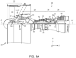
- Gas turbine engine 20 may be a two-spool turbofan that generally incorporates a fan section 22, a compressor section 24, a combustor section 26, and a turbine section 28.
- fan section 22 can drive air along a path of bypass airflow B while compressor section 24 can drive air along a core flow path C for compression and communication into combustor section 26 then expansion through turbine section 28.
- turbofan gas turbine engine depicted as a turbofan gas turbine engine herein, it should be understood that the concepts described herein are not limited to use with turbofans as the teachings may be applied to other types of turbine engines including three-spool architectures, single spool architecture, or the like.
- Gas turbine engine 20 may generally include a low speed spool 30 and a high speed spool 32 mounted for rotation about an engine central longitudinal axis A-A' (e.g., parallel to the z-axis) relative to an engine static structure 36 or engine case via several bearing systems 38, 38-1, etc. It should be understood that various bearing systems 38 at various locations may alternatively or additionally be provided, including for example, bearing system 38, bearing system 38-1, etc.
- Low speed spool 30 may generally include an inner shaft 40 that interconnects a fan 42, a low pressure compressor 44, and a low pressure turbine 46.
- Inner shaft 40 may be connected to fan 42 through a geared architecture 48 that can drive fan 42 at a lower speed than low speed spool 30.
- Geared architecture 48 may include a gear assembly 60 enclosed within a gear housing 62.
- Gear assembly 60 couples inner shaft 40 to a rotating fan structure.
- High speed spool 32 may include an outer shaft 50 that interconnects a high pressure compressor 52 and high pressure turbine 54.
- a combustor 56 may be located between high pressure compressor 52 and high pressure turbine 54.
- a mid-turbine frame 57 of engine static structure 36 may be located generally between high pressure turbine 54 and low pressure turbine 46.
- Mid-turbine frame 57 may support one or more bearing systems 38 in turbine section 28.
- Inner shaft 40 and outer shaft 50 may be concentric and rotate via bearing systems 38 about the engine central longitudinal axis A-A', which is collinear with their longitudinal axes.
- A-A' the engine central longitudinal axis A-A'
- the core airflow may be compressed by low pressure compressor 44 then high pressure compressor 52, mixed and burned with fuel in combustor 56, then expanded over high pressure turbine 54 and low pressure turbine 46.
- Turbines 46, 54 rotationally drive the respective low speed spool 30 and high speed spool 32 in response to the expansion.
- compressor 80 may be an example of low pressure compressor 44. In various embodiments, compressor 80 may be an example of high pressure compressor 52.
- Compressor 80 includes a plurality of blade stages 101 (i.e., rotor stages) and a plurality of vane stages 105 (i.e., stator stages).
- Blade stages 101 may each include an integrally bladed rotor ("IBR") 100, such that the blades 103 and rotor disks 102 are formed from a single integral component (i.e., a monolithic component formed of a single piece).
- Blades 103 extend radially outward from rotor disks 102.
- Gas turbine engine 20 may further include an exit guide vane stage 106 that defines the aft end of compressor 80. Although illustrated with respect to compressor 80, the present disclosure is not limited in this regard.
- low pressure compressor 44 may include a plurality of blade stages 101 and stator stages 105, each blade stage in the plurality of blade stages 101 may include IBR 100 and still be within the scope of this disclosure.
- the plurality of blade stages 101 form a stack of IBRs 110, which define, at least partially, a rotor module 111 of compressor 80 of gas turbine engine 20.
- IBR 100 further includes a knife edge 108 of a knife edge seal assembly 109.
- Knife edge 108 is disposed between adjacent rotor stages in the plurality of blade stages 101 and configured to interface with a vane assembly in the plurality of vane stages 105.
- Each vane assembly in the plurality of vane stages 105 may include a partial or a complete circumferential array of vanes
- knife edge seal assembly 109 is configured to seal air flow from core flow path C during operation of the gas turbine engine 20 (as illustrated in FIG. 1A ).
- knife edge seal assembly 109 may be a labyrinth style seal assembly that is defined by vane stages 105 at one end and knife edge 108 at the other end.
- Knife edge seal assembly 109 may be a non-contact, tortuous path for airflow that effectively operates as a seal that reduces and/or prevents airflow between vane stages 105 and IBR 100.
- a vane subassembly 150 of a vane assembly in the plurality of vane stages 105 is illustrated, in accordance with various embodiments.
- the vane assembly, including vane subassembly 150 may include a partial or a complete circumferential array of vanes 120.
- the vane assembly may include a continuous annular vane assembly or a plurality of vane clusters or vane subassemblies 150.
- Vanes 120 may be grouped into vane subassemblies 150 and arranged circumferentially about engine central longitudinal axis A-A' (see FIG. 1A ) to form the vane assembly. Vane subassemblies 150 may be mounted in circumferentially abutting relationship to form an annular ring.
- Vane subassembly 150 may include a plurality of vanes 120 and a segment of inner shroud 140.
- Inner shroud 140 defines a plurality of apertures 152 configured to receive vanes 120.
- a radial flange 136 at a radially inner end 124 of vane 120 is configured to fit into an aperture 152 of inner shroud 140.
- a radial flange 136 of each vane 120 is received in a corresponding aperture 152 of the inner shroud 140.
- inner shroud 140 may be comprised of the same material or a similar material as vanes 120.
- Inner shroud 140 may be comprised of a composite material such as a fiber composite material and/or a fiber composite material infiltrated or impregnated with a resin, such as epoxy or other thermoset or a thermoplastic.
- the composite material of inner shroud 140 may comprise at least one of carbon fiber, glass fiber, aramid fiber, para-aramid fiber or a combination thereof impregnated with a resin.
- the composite material of inner shroud 140 may comprise a high temperature polymer such as an amorphous thermoplastic PEI, such as ULTEM ® , which is a trademark of SABIC Innovative Plastics, Inc.
- inner shroud 140 may be formed from a non-metallic carbon fiber reinforced epoxy resin.
- inner shroud 140 may be made from moldable materials, such as carbon and/or glass reinforced thermoset or thermoplastic. The material may be compression molded using an autoclave or injection molded by injecting material into a mold. The materials may be low cost, low weight materials shaped using low cost techniques. Accordingly, inner shroud 140 may reduce the weight and cost of a gas turbine engine.
- inner shroud 140 may be comprised of a metal, such as titanium, titanium-based alloy, aluminum, aluminum-based alloy or other alloy or suitable metal or alloy.
- the material of inner shroud 140 may be resistant to heat.
- the properties of materials use to form vanes 120 are compatible with the temperatures and pressures encountered during operation of IBR 100 (of FIG. 1B ).
- inner shroud 140 including a carbon fiber reinforced epoxy resin may be resistant to temperatures experienced in the IBR 100.
- vanes 120 may be attached to inner shroud 140 by a flexible material 154 disposed in aperture 152 between vane 120 and inner shroud 140.
- flexible material 154 can be a rubber potting material, such as natural rubber, synthetic rubber, silicone, or another elastomeric material.
- Flexible material 154 may be room temperature vulcanized (RTV) silicone or rubber or other thermoset material.
- RTV room temperature vulcanized
- Flexible material 154 can be applied within aperture 152 as a liquid and then allowed to cure or solidify.
- Flexible material 154 can hold vane 120 in a fixed position with respect to inner shroud 140 so as to be spaced from and avoid contact with inner shroud 140.
- Flexible material 154 adheres to and bonds vanes 120 to inner shroud 140 to provide a flexible connection between these components.
- Flexible material 154 supports and vibrationally isolates radial flange 136 of vane 120 relative to inner shroud 140.
- An integral seal 156 may be formed on or integral (i.e., monolithic) to an inner diameter surface 158 of inner shroud 140 opposite to vanes 120.
- integral seal 156 may be formed from the same material as vanes 120. Integral seal 156 may form the radially inner surface 144 of inner shroud 140 and may form a non-contact, tortuous path air seal.
- Vanes 120 may be mounted in a circumferentially abutting relationship to form vane subassembly 150, which may be portion of an annular vane assembly.
- each vane 120 may be a separate component from each adjacent vane 120.
- Each blade 103 may further include an outer shroud segment 160 disposed at radially outer end 122 of each vane 120.
- Each vane 120 includes a platform 130, which may be coupled to the vane 120 or integrally formed with the vane 120.
- a radially outer end 122 of each vane 120 with platform 130 may form an outer shroud segment 160.
- a plurality of outer shroud segments 160 may form outer diameter shroud 162 of a vane subassembly 150 or vane assembly 104.
- each vane 120 may include a discrete outer shroud segment 160 integral with the vane 120.
- the term "integrated” or “integral” may include forming one, single, monolithic, continuous piece.
- outer shroud segment 160 may be formed integrally with vane 120 as one continuous composite material by injection molding.
- outer shroud segment 160 may be comprised of the same material or a similar material as vanes 120.
- Outer shroud segment 160 may be comprised of a composite material such as a fiber composite material and/or a fiber composite material infiltrated or impregnated with a resin, such as epoxy or other thermoset or a thermoplastic.
- the composite material of outer shroud segment 160 may comprise at least one of carbon fiber, glass fiber, aramid fiber, para-aramid fiber or a combination thereof impregnated with a resin.
- the composite material of outer shroud segment 160 may comprise a high temperature polymer such as an amorphous thermoplastic PEI, such as ULTEM ® , which is a trademark of SABIC Innovative Plastics, Inc.
- outer shroud segment 160 may be formed from a non-metallic carbon fiber reinforced epoxy resin.
- outer shroud segment 160 may be made from moldable materials, such as carbon and/or glass reinforced thermoset or thermoplastic. The material may be compression molded using an autoclave or injection molded by injecting material into a mold. The materials may be low cost, low weight materials shaped using low cost techniques. Accordingly, outer shroud segment 160 may reduce the weight and cost of a gas turbine engine. The composite material of outer shroud segment 160 may be resistant to heat. In various embodiments, the properties of materials use to form vanes 120 are compatible with the temperatures and pressures encountered during operation of IBR 100 (of FIG. 1B ).
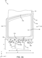
- stator vane assembly 300 (e.g., from vane subassembly 150) is illustrated, in accordance with various embodiments.
- stator vane assembly 300 may be an example of vane 120 described above with respect to FIG. 2 .
- Stator vane assembly 300 a stator box 302, a vane 304, and an integral seal 306.
- Stator box 302 includes an opening 308 defined by an outer diameter 310.
- Outer diameter 310 includes a first side 310a, a second side 310b, a bottom 310c, and a top 310d.
- Vane 304 is coupled to top 310d of stator box 302.
- stator vane assembly 300 may be configured to move forward (e.g., in the negative z-direction) and aft (e.g., in the positive z-direction) with respect to a rotor (e.g., rotor module 111).
- Stator box 302 has a width w1 (e.g., parallel to the z-axis) from first side 310a to second side 310b.
- Stator box 302, and more specifically bottom 310c of stator box 302 is a height h1 (e.g., parallel to the y-axis) away from the rotor assembly (e.g., IBR 100).
- Width w1 and height h1 vary based on individual embodiments and implementations and are used below as a reference width and height, respectively.
- Integral seal 306 is coupled to bottom 310c of stator box 302.
- integral seal 306 and stator box 302 form a single, monolithic component.
- integral seal 306, stator box 302, and vane 304 form a single monolithic component.
- Integral seal 306 extends away from stator box 302 and toward the rotor module (e.g., in the negative y-direction).
- Integral seal 306 has a width w2 (e.g., parallel to the z-axis) and a height h2 (e.g., parallel to the y-axis). Width w2 is about 50% to about 90% of width w1, and more specifically, about 60% to about 75% of width w1.
- integral seal 306 includes a plurality of extended portions interleaved with a plurality of recessed portions.
- integral seal 306, including the plurality of extended and recess portions is configured as a labyrinth style seal with integral seal 306 being a first half of the labyrinth style seal and one or more plate seals 312 being a second half of the labyrinth seal.
- the one or more plate seals 312 may be an example of knife edge 108 described above with respect to FIG. 1B .
- the one or more plate seals 312 include a top portion 312a that extends upward from the rotor assembly (e.g., in the positive y-direction) and between two or more of the plurality of extended portions, as will be described in further detail below.
- integral seal 306 includes a first extended portion 306a, a first recessed portion 306b, a second extended portion 306c, a second recessed portion 306d, and a third extended portion 306e.
- Each of the plurality of extended portions 306a, 306c, 306e and each of the plurality of recessed portions 306b, 306d have an associated width (e.g., parallel to the z-axis) and height (e.g., parallel to the y-axis).
- each portion 306a-306e of integral seal 306 is illustrated as having vertical edges (e.g., parallel to the y-axis).
- one or more portion 306a-306e of integral seal 306 may include one or more edges that are sloped (e.g., not parallel to the y-axis).
- a bottom surface of each portion 306a-306e may be horizontal (e.g., parallel to the z-axis).
- the bottom surface of each portion 306a-306e may be non-horizontal (e.g., not parallel to the z-axis).
- First extended portion 306a has a width w3 (e.g., parallel to the z-axis) from a left side (e.g., the negative z-direction) of integral seal 306 to first recessed portion 306b.
- width w3 may be determined based on various design parameters including width w1 of stator box 302, height h1 between the rotor assembly and stator box 302, and/or desired airflow obstruction, among others.
- First extended portion 306a has a height h3 (e.g., parallel to the y-axis) that is about 20% to about 90% of height h1, and more specifically about 30% to about 70% of height h1.
- first extended portion 306a may extend below top portion 312a of plate seal 312.
- First recessed portion 306b has a width w4 (e.g., parallel to the z-axis) from first extended portion 306a to second extended portion 306c.
- width w4 may be designed to account for movement of stator vane assembly 300 (e.g., along the z-axis). That is, width w4 may be about 105% to about 115% of a range of motion of stator vane assembly 300, and more specifically, about 100% of the range of motion of stator vane assembly 300.
- First recessed portion 306b has a height h4 (e.g., parallel to the y-axis) that is less than height h1.
- First recessed portion 306b is disposed over a first plate seal 312 and height h4 is designed such that first recessed portion 306b does not extend to top portion 312a of the first plate seal 312.
- Second extended portion 306c has a width w5 (e.g., parallel to the z-axis) from first recessed portion 306b to second recessed portion 306d. and a height h5 (e.g., parallel to the y-axis).
- width w5 may be determined based on various design parameters including width w1 of stator box 302, height h1 between the rotor assembly and stator box 302, and/or desired airflow obstruction, among others.
- Second extended portion 306c has a height h5 (e.g., parallel to the y-axis) that is about 20% to about 90% of height h1, and more specifically about 30% to about 70% of height h1.
- first extended portion 306a may extend below top portion 312a of plate seal 312.
- Second recessed portion 306d has a width w6 (e.g., parallel to the z-axis) from second extended portion 306c to third extended portion 306e.
- width w6 may be designed to account for movement of stator vane assembly 300 (e.g., along the z-axis). That is, width w6 may be about 105% to about 115% of a range of motion of stator vane assembly 300, and more specifically, about 100% of the range of motion of stator vane assembly 300.
- Second recessed portion 306d has a height h6 (e.g., parallel to the y-axis) that is less than height h1. Second recessed portion 306d is disposed over a second plate seal 312 and height h6 is designed such that second recessed portion 306d does not extend to top portion 312a of the second plate seal 312.
- Third extended portion 306e has a width w7 (e.g., parallel to the z-axis) from second recessed portion 306d to a right side of integral seal 306 (e.g., in the positive z-direction).
- width w7 may be determined based on various design parameters including width w1 of stator box 302, height h1 between the rotor assembly and stator box 302, and/or desired airflow obstruction, among others.
- Third extended portion 306e has a height h7 (e.g., parallel to the y-axis) that is about 20% to about 90% of height h1, and more specifically about 30% to about 70% of height h1.
- first extended portion 306a may extend below top portion 312a of plate seal 312.
- Integral seal 306 as described above, is configured to provide a non-contact, tortuous path for air flow between stator box 302 and the rotor assembly. Integral seal 306 and plate seals 312 reduce and/or eliminate secondary airflow between bottom 310c of stator box 302 and the rotor assembly. In various embodiments, integral seal 306 is formed as a part of stator box 302. In various embodiments, this configuration increases the maximum temperature capability of stator vane assembly 300. In various embodiments, this configuration reduces risks that are present when an abradable material is bonded to stator box 302, as is typically done to form a seal between stator vane assembly 300 and the rotor assembly.
- stator vane assembly 300 and more specifically, integral seal 306 may be more durable than typical seals that are bonded to stator box 302.
- integral seal 306 may improve the efficiency of the engage (e.g., gas turbine engine 20) by enabling an expanded design space, due to the higher durability and temperature capability.
- integral seal 306 may allow for improved seal geometries.
- integral seal 306 may decrease costs associated with production of stator vane assembly 300 by reducing and/or eliminating the manufacturing, bonding, and/or inspections associated with the typical bonded seals designs. Referring now to FIG.
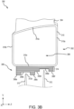
- stator vane assembly 350 (e.g., from vane subassembly 150) is illustrated, in accordance with various embodiments.
- stator vane assembly 350 may be an example of vane 120 described above with respect to FIG. 2 .
- Stator vane assembly 350 includes similar components to those described above with respect to stator vane assembly 300 in FIG. 3A , including stator box 302, vane 304, opening 308, and outer diameter 310 including first side 310a, second side 31 0b, bottom 310c, and top 310d. Description of similar components may not be repeated below.
- Stator vane assembly 350 further includes an integral seal 356 coupled to bottom 310c of stator box 302.
- Integral seal 356 includes a first extended portion 356a, a first recessed portion 356b, a second extended portion 356c, a third recessed portion 356d, a fourth recessed portion 356e, and a third extended portion 356f.
- integral seal 356 be formed of a plurality of plies 314 (also referred to as layers).
- each ply of the plurality of plies 314 may be about 6 mils to about 10 mils thick, and more specifically, about 7.5 mils to about 8 mils thick.
- plate seals 312, including top portions 312a extend upward (e.g., in the positive y-direction) from the rotor assembly.
- Integral seal 356 is designed so that top portions 312a of plate seals 312 are between first extended portion 356a and second extended portion 356c and between third recessed portion 356d and third extended portion 356f.
- the plurality of portions 356a-356f have various widths and heights such that the recessed portions 356b, 356e are disposed over plate seals 312 and do not contact top portion 312a of plate seals 312. Additionally, the widths of recessed portions 356b, 356e are sufficient to allow stator vane assembly 350 to move forward (e.g., in the negative z-direction) and aft (e.g., in the positive z-direction) without integral seal 356 contacting plate seals 312.
- plies 314 may be formed along bottom 310c of stator box during manufacture of stator box 302. In various embodiments, plies 314 may wrap around outer diameter 310 of stator box 302. In various embodiments, plies 314 may be formed during an additive manufacturing process, a hand layup process, or an automated tape laying process, among others.
- stator vane assembly having an integral seal
- the stator vane assembly may be an example of stator vane assembly 300 or stator vane assembly 350 described above with respect to FIGS. 3A and 3B .
- the integral seal may be an example of integral seal 306 or integral seal 356 described above with respect to FIGS. 3A and 3B .
- a design for stator box 302 is received.
- the design may be a mold or a preform used to form stator box 302.
- the design may a computer file including instructions for manufacturing stator box 302 using, for example, an additive manufacturing process.
- stator box 302 is formed using the received mold.
- stator box 302 is formed using molding process.
- stator box 302 is formed using a hand layup, additive manufacturing, or an automated tape laying process, among others.
- the integral seal e.g., integral seal 306, integral seal 356) is formed as part of stator box 302.
- step 404 and step 406 are performed simultaneously, such as with a molding or a preform manufacturing process. That is, stator box 302 and the integral seal are formed as a single monolithic component during the same process. In various embodiments, stator box 302 and the integral seal are formed through multiple passes of a manufacturing process (e.g., hand layup, additive manufacturing, etc.). In various embodiments, each pass of the manufacturing process may deposit a single ply where each ply is about 7.5 mils to about 8 mils thick. In various embodiments, each ply may form a portion of stator box 302 and/or the integral seal. In various embodiments, while step 406 may include more passes than step 404, stator box 302 and the integral seal are manufactured as a single, monolithic component.
- a manufacturing process e.g., hand layup, additive manufacturing, etc.
- references to "one embodiment,” “an embodiment,” “various embodiments,” etc. indicate that the embodiment described may include a particular feature, structure, or characteristic, but every embodiment may not necessarily include the particular feature, structure, or characteristic. Moreover, such phrases are not necessarily referring to the same embodiment. Further, when a particular feature, structure, or characteristic is described in connection with an embodiment, it is submitted that it is within the knowledge of one skilled in the art to affect such feature, structure, or characteristic in connection with other embodiments whether or not explicitly described. After reading the description, it will be apparent to one skilled in the relevant art(s) how to implement the disclosure in alternative embodiments.
- Numbers, percentages, or other values stated herein are intended to include that value, and also other values that are about or approximately equal to the stated value, as would be appreciated by one of ordinary skill in the art encompassed by various embodiments of the present disclosure.
- a stated value should therefore be interpreted broadly enough to encompass values that are at least close enough to the stated value to perform a desired function or achieve a desired result.
- the stated values include at least the variation to be expected in a suitable industrial process, and may include values that are within 5% of a stated value.
- the terms “substantially,” “about” or “approximately” as used herein represent an amount close to the stated amount that still performs a desired function or achieves a desired result.
- the term “substantially,” “about” or “approximately” may refer to an amount that is within 5% of a stated amount or value.
Landscapes
- Engineering & Computer Science (AREA)
- General Engineering & Computer Science (AREA)
- Mechanical Engineering (AREA)
- Structures Of Non-Positive Displacement Pumps (AREA)
Abstract
A stator vane assembly (300; 350) is disclosed herein. The stator vane assembly (300; 350) includes a stator box (302) having a top side and a bottom side, a vane coupled to the top side of the stator box (302), and an integral seal (306; 356) coupled to the bottom side of the stator box (302), the integral seal (356) extending away from the stator box (302) and forming a tortuous path to prevent airflow below the stator box (302).
Description
- The present disclosure relates to a gas turbine engine and, more specifically, to a stator vane assembly.
- Gas turbine engines (such as those used in electrical power generation or used in modern aircraft) typically include a fan section, a compressor section, a combustor section and a turbine section. In general, during operation, air is pressurized in the compressor section and is mixed with fuel and burned in the combustor section to generate hot combustion gases. The hot combustion gases flow through the turbine section, which extracts energy from the hot combustion gases to power the compressor section and other gas turbine engine loads. One or more sections of the gas turbine engine may include a series of alternating rotor assemblies and stator assemblies. Stator assemblies may include plurality of stator vane assemblies having stator vanes interspersed between the rotor assemblies. Typically, air seals are secondarily bonded to each of the plurality of stator vanes to limit secondary air flow through the compressor. Secondary airflow is air flow, or leakage, in opposite direction of the primary path of intake air through successive rotor/stator stages. Generally, secondary air flow occurs through cavities located inboard or outboard of the compressor flowpath end walls
- In accordance with an aspect of the present invention, there is provided a stator vane assembly is disclosed herein. The stator vane assembly includes a stator box having a top side and a bottom side, a vane coupled to the top side of the stator box, and an integral seal coupled to the bottom side of the stator box, the integral seal extending away from the stator box and forming a tortuous path to prevent airflow below the stator box.
- In various embodiments, the integral seal further includes a plurality of extended portions, and a plurality of recessed portions interleaved with the plurality of extended portions. In various embodiments, the stator vane assembly is configured to move forward and aft a first distance and wherein each of the plurality of recessed portions has a width that is greater than the first distance. In various embodiments, the stator box and the integral seal are a single, monolithic component.
- In various embodiments, the stator box and the integral seal are formed from the same material. In various embodiments, the integral seal further includes a first portion that extends away from the stator box a first height, and a second portion that extends away from the stator box a second height, the second height being less than the first height. In various embodiments, the first portion includes a first edge and a second edge, the second edge being adjacent the second portion, wherein the first edge has a non-vertical slope. In various embodiments, the first portion includes a first edge and the second portion includes a second edge, wherein the first edge and the second are vertical. In various embodiments, the integral seal is formed of a plurality of plies.
- In accordance with an aspect of the present invention, there is provided a gas turbine engine including a rotor assembly and a plate seal, and a vane assembly including a stator vane assembly. The stator vane assembly includes a stator box having a top side and a bottom side, a vane coupled to the top side of the stator box, and an integral seal coupled to the bottom side of the stator box, the integral seal extending away from the stator box toward the rotor assembly, the integral seal and the plate seal combining to form a tortuous path to reduce airflow between the rotor assembly and the vane assembly.
- In various embodiments, the integral seal further includes a plurality of extended portions, and a plurality of recessed portions interleaved with the plurality of extended portions, a recessed portion of the plurality of recessed portions disposed over the plate seal. In various embodiments, the vane assembly is configured to move forward and aft a first distance with respect to the rotor assembly, and wherein each of the plurality of recessed portions has a width that is greater than the first distance. In various embodiments, the stator vane assembly is a single monolithic component.
- In various embodiments, the integral seal includes a first edge and a second edge, the first edge and the second edge being vertical. In various embodiments, the integral seal includes a first edge and a second edge, the first edge and the second edge being non-vertical. In various embodiments, the stator vane assembly is formed from a plurality of plies that are formed on top of each other.
- In accordance with an aspect of the present invention, there is provided a method of manufacturing a stator vane assembly. The method includes receiving a design for the stator vane assembly, the stator vane assembly including a vane, a stator box, and an integral seal, forming the stator box of the stator vane assembly, and forming the integral seal of the stator vane assembly, the integral seal being coupled to the stator box.
- In various embodiments, the design includes one of a mold or a preform. In various embodiments, the design includes a computer file including instructions for forming the stator box and the integral seal as a single monolithic component using at least one of an additive manufacturing or an automated tape laying process. In various embodiments, the computer file is a computer program comprising the instructions. The program may be executed by a computer. In various embodiments, a computer-readable data carrier may have stored thereon the computer program. In various embodiments, the forming the stator box and the forming the integral seal includes forming a series of plies that define the stator box and the integral seal.
- The foregoing features and elements may be combined in any combination, without exclusivity, unless expressly indicated herein otherwise. These features and elements as well as the operation of the disclosed embodiments will become more apparent in light of the following description and accompanying drawings.
- The subject matter of the present disclosure is particularly pointed out and distinctly claimed in the concluding portion of the specification. A more complete understanding of the present disclosure, however, may best be obtained by referring to the following detailed description and claims in connection with the following drawings. While the drawings illustrate various embodiments employing the principles described herein, the drawings do not limit the scope of the claims.
-
FIG. 1A illustrates a cross-sectional view of a gas-turbine engine, in accordance with various embodiments. -
FIG. 1B illustrates a cross-sectional view of a compressor, in accordance with various embodiments. -
FIG. 2 illustrates a fragmentary perspective view of a stator vane assembly of a gas turbine engine, in accordance with various embodiments. -
FIGS. 3A and3B illustrate a stator vane assembly including an integral seal, in accordance with various embodiments. -
FIG. 4 illustrates a method of manufacture of a stator vane assembly including an integral seal, in accordance with various embodiments. - The following detailed description of various embodiments herein makes reference to the accompanying drawings, which show various embodiments by way of illustration. While these various embodiments are described in sufficient detail to enable those skilled in the art to practice the disclosure, it should be understood that other embodiments may be realized and that changes may be made without departing from the scope of the disclosure. Thus, the detailed description herein is presented for purposes of illustration only and not of limitation. While these exemplary embodiments are described in sufficient detail to enable those skilled in the art to practice the invention, it should be understood that other embodiments may be realized and that logical, chemical and mechanical changes may be made without departing from the invention. For example, the steps recited in any of the method or process descriptions may be executed in any order and are not necessarily limited to the order presented. Furthermore, any reference to singular includes plural embodiments, and any reference to more than one component or step may include a singular embodiment or step. Also, any reference to attached, fixed, connected, or the like may include permanent, removable, temporary, partial, full or any other possible attachment option. Additionally, any reference to without contact (or similar phrases) may also include reduced contact or minimal contact. It should also be understood that unless specifically stated otherwise, references to "a," "an" or "the" may include one or more than one and that reference to an item in the singular may also include the item in the plural. Further, all ranges may include upper and lower values and all ranges and ratio limits disclosed herein may be combined.
- As used herein, "aft" refers to the direction associated with the tail (e.g., the back end) of an aircraft, or generally, to the direction of exhaust of the gas turbine. As used herein, "forward" refers to the direction associated with the nose (e.g., the front end) of an aircraft, or generally, to the direction of flight or motion.
- Disclosed herein is a stator vane assembly including an integral seal for use in a gas turbine engine. In various embodiments, the stator vane assembly may be used in a compressor of the gas turbine engine, the compressor including stator vane assemblies and a rotor assembly. In various embodiments, the integral seal is formed to a bottom portion of a stator box that is part of the stator vane assembly. In various embodiments, the integral seal includes a plurality of extended portions interleaved with a plurality of recessed portions. In various embodiments, the recessed portions are located over plate seals, or a knife edge, that are coupled to a rotor assembly. The integral seal is configured to not contact the plate seals as they rotate with the rotor assembly. In various embodiments, the extended portions extend below a top surface of the plate seals. In various embodiments, the width of the recessed portions is sufficient to allow the stator vane assembly to move forward and aft, with respect to the rotor assembly, without contacting the plate seals. The integral seal and the plate seals may form a labyrinth seal that creates a tortuous path for air to pass through and therefore creates a seal to block air from passing through. A tortuous path may be a circuitous, convoluted, indirect, or labyrinthine path that is twisting, winding, and/or curving. A tortuous path may further be considered a meandering or serpentine path. In other words, a tortuous path is a non-linear path including one or more obstacles to impede air flow along the path. In various embodiments, the integral seal is molded as part of the stator box during manufacture of the stator vane assembly. In various embodiments, the integral seal and the stator box may be formed as a single, monolithic unit using hand layup, additive manufacturing, automated tape laying, chopped fiber, and/or preform techniques, among others, to facilitate manufacturing. In various embodiments, the stator vane assembly including the integral seal may improve the efficiency of the gas turbine engine. In various embodiments, the stator vane assembly including the integral seal may reduce and/or eliminate the manufacturing, bonding, and/or inspections associated with typical seal designs.
- Referring now to
FIG. 1A , a gas turbine engine 20 is illustrated, in accordance with various embodiments. Gas turbine engine 20 may be a two-spool turbofan that generally incorporates afan section 22, acompressor section 24, acombustor section 26, and aturbine section 28. - In operation,
fan section 22 can drive air along a path of bypass airflow B whilecompressor section 24 can drive air along a core flow path C for compression and communication intocombustor section 26 then expansion throughturbine section 28. Although depicted as a turbofan gas turbine engine herein, it should be understood that the concepts described herein are not limited to use with turbofans as the teachings may be applied to other types of turbine engines including three-spool architectures, single spool architecture, or the like. - Gas turbine engine 20 may generally include a
low speed spool 30 and ahigh speed spool 32 mounted for rotation about an engine central longitudinal axis A-A' (e.g., parallel to the z-axis) relative to an enginestatic structure 36 or engine case viaseveral bearing systems 38, 38-1, etc. It should be understood that various bearingsystems 38 at various locations may alternatively or additionally be provided, including for example, bearingsystem 38, bearing system 38-1, etc. -
Low speed spool 30 may generally include aninner shaft 40 that interconnects afan 42, alow pressure compressor 44, and alow pressure turbine 46.Inner shaft 40 may be connected to fan 42 through a gearedarchitecture 48 that can drivefan 42 at a lower speed thanlow speed spool 30.Geared architecture 48 may include agear assembly 60 enclosed within agear housing 62.Gear assembly 60 couplesinner shaft 40 to a rotating fan structure.High speed spool 32 may include anouter shaft 50 that interconnects ahigh pressure compressor 52 andhigh pressure turbine 54. Acombustor 56 may be located betweenhigh pressure compressor 52 andhigh pressure turbine 54. Amid-turbine frame 57 of enginestatic structure 36 may be located generally betweenhigh pressure turbine 54 andlow pressure turbine 46.Mid-turbine frame 57 may support one ormore bearing systems 38 inturbine section 28.Inner shaft 40 andouter shaft 50 may be concentric and rotate via bearingsystems 38 about the engine central longitudinal axis A-A', which is collinear with their longitudinal axes. As used herein, a "high pressure" compressor or turbine experiences a higher pressure than a corresponding "low pressure" compressor or turbine. - The core airflow may be compressed by
low pressure compressor 44 thenhigh pressure compressor 52, mixed and burned with fuel incombustor 56, then expanded overhigh pressure turbine 54 andlow pressure turbine 46.Turbines low speed spool 30 andhigh speed spool 32 in response to the expansion. - Referring now to
FIG. 1B , a cross section of acompressor 80 of thecompressor section 24 of gas turbine engine 20 is illustrated, in accordance with various embodiments. In various embodiments,compressor 80 may be an example oflow pressure compressor 44. In various embodiments,compressor 80 may be an example ofhigh pressure compressor 52. -
Compressor 80 includes a plurality of blade stages 101 (i.e., rotor stages) and a plurality of vane stages 105 (i.e., stator stages). Blade stages 101 may each include an integrally bladed rotor ("IBR") 100, such that theblades 103 androtor disks 102 are formed from a single integral component (i.e., a monolithic component formed of a single piece).Blades 103 extend radially outward fromrotor disks 102. Gas turbine engine 20 may further include an exitguide vane stage 106 that defines the aft end ofcompressor 80. Although illustrated with respect tocompressor 80, the present disclosure is not limited in this regard. For example,low pressure compressor 44 may include a plurality of blade stages 101 and stator stages 105, each blade stage in the plurality of blade stages 101 may includeIBR 100 and still be within the scope of this disclosure. In various embodiments, the plurality of blade stages 101 form a stack ofIBRs 110, which define, at least partially, arotor module 111 ofcompressor 80 of gas turbine engine 20. -
IBR 100 further includes aknife edge 108 of a knifeedge seal assembly 109.Knife edge 108 is disposed between adjacent rotor stages in the plurality of blade stages 101 and configured to interface with a vane assembly in the plurality of vane stages 105. Each vane assembly in the plurality of vane stages 105 may include a partial or a complete circumferential array of vanes In various embodiments, knifeedge seal assembly 109 is configured to seal air flow from core flow path C during operation of the gas turbine engine 20 (as illustrated inFIG. 1A ). In various embodiments, knifeedge seal assembly 109 may be a labyrinth style seal assembly that is defined byvane stages 105 at one end andknife edge 108 at the other end. Knifeedge seal assembly 109 may be a non-contact, tortuous path for airflow that effectively operates as a seal that reduces and/or prevents airflow between vane stages 105 andIBR 100. Referring now toFIG. 2 , avane subassembly 150 of a vane assembly in the plurality of vane stages 105 is illustrated, in accordance with various embodiments. The vane assembly, includingvane subassembly 150, may include a partial or a complete circumferential array ofvanes 120. In various embodiments, the vane assembly may include a continuous annular vane assembly or a plurality of vane clusters orvane subassemblies 150.Vanes 120 may be grouped intovane subassemblies 150 and arranged circumferentially about engine central longitudinal axis A-A' (seeFIG. 1A ) to form the vane assembly.Vane subassemblies 150 may be mounted in circumferentially abutting relationship to form an annular ring. -
Vane subassembly 150 may include a plurality ofvanes 120 and a segment ofinner shroud 140.Inner shroud 140 defines a plurality ofapertures 152 configured to receivevanes 120. Aradial flange 136 at a radiallyinner end 124 ofvane 120 is configured to fit into anaperture 152 ofinner shroud 140. Aradial flange 136 of eachvane 120 is received in acorresponding aperture 152 of theinner shroud 140. - In various embodiments,
inner shroud 140 may be comprised of the same material or a similar material asvanes 120.Inner shroud 140 may be comprised of a composite material such as a fiber composite material and/or a fiber composite material infiltrated or impregnated with a resin, such as epoxy or other thermoset or a thermoplastic. The composite material ofinner shroud 140 may comprise at least one of carbon fiber, glass fiber, aramid fiber, para-aramid fiber or a combination thereof impregnated with a resin. The composite material ofinner shroud 140 may comprise a high temperature polymer such as an amorphous thermoplastic PEI, such as ULTEM®, which is a trademark of SABIC Innovative Plastics, Inc. For example,inner shroud 140 may be formed from a non-metallic carbon fiber reinforced epoxy resin. In various embodiments,inner shroud 140 may be made from moldable materials, such as carbon and/or glass reinforced thermoset or thermoplastic. The material may be compression molded using an autoclave or injection molded by injecting material into a mold. The materials may be low cost, low weight materials shaped using low cost techniques. Accordingly,inner shroud 140 may reduce the weight and cost of a gas turbine engine. - In various embodiments,
inner shroud 140 may be comprised of a metal, such as titanium, titanium-based alloy, aluminum, aluminum-based alloy or other alloy or suitable metal or alloy. The material ofinner shroud 140 may be resistant to heat. In various embodiments, the properties of materials use to formvanes 120 are compatible with the temperatures and pressures encountered during operation of IBR 100 (ofFIG. 1B ). In various embodiments,inner shroud 140 including a carbon fiber reinforced epoxy resin may be resistant to temperatures experienced in theIBR 100. - In various embodiments,
vanes 120 may be attached toinner shroud 140 by aflexible material 154 disposed inaperture 152 betweenvane 120 andinner shroud 140. In various embodiments,flexible material 154 can be a rubber potting material, such as natural rubber, synthetic rubber, silicone, or another elastomeric material.Flexible material 154 may be room temperature vulcanized (RTV) silicone or rubber or other thermoset material.Flexible material 154 can be applied withinaperture 152 as a liquid and then allowed to cure or solidify.Flexible material 154 can holdvane 120 in a fixed position with respect toinner shroud 140 so as to be spaced from and avoid contact withinner shroud 140.Flexible material 154 adheres to andbonds vanes 120 toinner shroud 140 to provide a flexible connection between these components.Flexible material 154 supports and vibrationally isolatesradial flange 136 ofvane 120 relative toinner shroud 140. - An
integral seal 156 may be formed on or integral (i.e., monolithic) to aninner diameter surface 158 ofinner shroud 140 opposite to vanes 120. In various embodiments,integral seal 156 may be formed from the same material asvanes 120.Integral seal 156 may form the radiallyinner surface 144 ofinner shroud 140 and may form a non-contact, tortuous path air seal. -
Vanes 120 may be mounted in a circumferentially abutting relationship to formvane subassembly 150, which may be portion of an annular vane assembly. In various embodiments, eachvane 120 may be a separate component from eachadjacent vane 120. Eachblade 103 may further include anouter shroud segment 160 disposed at radiallyouter end 122 of eachvane 120. Eachvane 120 includes aplatform 130, which may be coupled to thevane 120 or integrally formed with thevane 120. A radiallyouter end 122 of eachvane 120 withplatform 130 may form anouter shroud segment 160. A plurality ofouter shroud segments 160 may formouter diameter shroud 162 of avane subassembly 150 or vane assembly 104. Thus, eachvane 120 may include a discreteouter shroud segment 160 integral with thevane 120. As used herein, the term "integrated" or "integral" may include forming one, single, monolithic, continuous piece. In various embodiments,outer shroud segment 160 may be formed integrally withvane 120 as one continuous composite material by injection molding. - In various embodiments,
outer shroud segment 160 may be comprised of the same material or a similar material asvanes 120.Outer shroud segment 160 may be comprised of a composite material such as a fiber composite material and/or a fiber composite material infiltrated or impregnated with a resin, such as epoxy or other thermoset or a thermoplastic. The composite material ofouter shroud segment 160 may comprise at least one of carbon fiber, glass fiber, aramid fiber, para-aramid fiber or a combination thereof impregnated with a resin. The composite material ofouter shroud segment 160 may comprise a high temperature polymer such as an amorphous thermoplastic PEI, such as ULTEM®, which is a trademark of SABIC Innovative Plastics, Inc. For example,outer shroud segment 160 may be formed from a non-metallic carbon fiber reinforced epoxy resin. In various embodiments,outer shroud segment 160 may be made from moldable materials, such as carbon and/or glass reinforced thermoset or thermoplastic. The material may be compression molded using an autoclave or injection molded by injecting material into a mold. The materials may be low cost, low weight materials shaped using low cost techniques. Accordingly,outer shroud segment 160 may reduce the weight and cost of a gas turbine engine. The composite material ofouter shroud segment 160 may be resistant to heat. In various embodiments, the properties of materials use to formvanes 120 are compatible with the temperatures and pressures encountered during operation of IBR 100 (ofFIG. 1B ). - Referring now to
FIG. 3A , a stator vane assembly 300 (e.g., from vane subassembly 150) is illustrated, in accordance with various embodiments. In various embodiments,stator vane assembly 300 may be an example ofvane 120 described above with respect toFIG. 2 . Stator vane assembly 300 astator box 302, avane 304, and anintegral seal 306.Stator box 302 includes anopening 308 defined by anouter diameter 310.Outer diameter 310 includes afirst side 310a, asecond side 310b, a bottom 310c, and a top 310d.Vane 304 is coupled to top 310d ofstator box 302. In various embodiments,vane 304 andstator box 302 form a single monolithic component. In various embodiments,stator vane assembly 300 may be configured to move forward (e.g., in the negative z-direction) and aft (e.g., in the positive z-direction) with respect to a rotor (e.g., rotor module 111).Stator box 302 has a width w1 (e.g., parallel to the z-axis) fromfirst side 310a tosecond side 310b.Stator box 302, and more specifically bottom 310c ofstator box 302, is a height h1 (e.g., parallel to the y-axis) away from the rotor assembly (e.g., IBR 100). Width w1 and height h1 vary based on individual embodiments and implementations and are used below as a reference width and height, respectively. -
Integral seal 306 is coupled to bottom 310c ofstator box 302. In various embodiments,integral seal 306 andstator box 302 form a single, monolithic component. In various embodiments,integral seal 306,stator box 302, andvane 304 form a single monolithic component.Integral seal 306 extends away fromstator box 302 and toward the rotor module (e.g., in the negative y-direction).Integral seal 306 has a width w2 (e.g., parallel to the z-axis) and a height h2 (e.g., parallel to the y-axis). Width w2 is about 50% to about 90% of width w1, and more specifically, about 60% to about 75% of width w1. Height h2 is about 20% to about 90% of height h1, and more specifically about 30% to about 70% of height h1. In various embodiments,integral seal 306 includes a plurality of extended portions interleaved with a plurality of recessed portions. In various embodiments,integral seal 306, including the plurality of extended and recess portions is configured as a labyrinth style seal withintegral seal 306 being a first half of the labyrinth style seal and one or more plate seals 312 being a second half of the labyrinth seal. In various embodiments, the one or more plate seals 312 may be an example ofknife edge 108 described above with respect toFIG. 1B . The one or more plate seals 312 include atop portion 312a that extends upward from the rotor assembly (e.g., in the positive y-direction) and between two or more of the plurality of extended portions, as will be described in further detail below. In the illustrated embodiments,integral seal 306 includes a firstextended portion 306a, a first recessedportion 306b, a secondextended portion 306c, a second recessedportion 306d, and a thirdextended portion 306e. Each of the plurality ofextended portions portions - In the illustrated embodiment, each
portion 306a-306e ofintegral seal 306 is illustrated as having vertical edges (e.g., parallel to the y-axis). In various embodiments, one ormore portion 306a-306e ofintegral seal 306 may include one or more edges that are sloped (e.g., not parallel to the y-axis). In various embodiments, a bottom surface of eachportion 306a-306e may be horizontal (e.g., parallel to the z-axis). In various embodiments, the bottom surface of eachportion 306a-306e may be non-horizontal (e.g., not parallel to the z-axis). Firstextended portion 306a has a width w3 (e.g., parallel to the z-axis) from a left side (e.g., the negative z-direction) ofintegral seal 306 to first recessedportion 306b. In various embodiments, width w3 may be determined based on various design parameters including width w1 ofstator box 302, height h1 between the rotor assembly andstator box 302, and/or desired airflow obstruction, among others. Firstextended portion 306a has a height h3 (e.g., parallel to the y-axis) that is about 20% to about 90% of height h1, and more specifically about 30% to about 70% of height h1. In various embodiments, firstextended portion 306a may extend belowtop portion 312a ofplate seal 312. - First recessed
portion 306b has a width w4 (e.g., parallel to the z-axis) from firstextended portion 306a to secondextended portion 306c. In various embodiments, width w4 may be designed to account for movement of stator vane assembly 300 (e.g., along the z-axis). That is, width w4 may be about 105% to about 115% of a range of motion ofstator vane assembly 300, and more specifically, about 100% of the range of motion ofstator vane assembly 300. First recessedportion 306b has a height h4 (e.g., parallel to the y-axis) that is less than height h1. First recessedportion 306b is disposed over afirst plate seal 312 and height h4 is designed such that first recessedportion 306b does not extend totop portion 312a of thefirst plate seal 312. - Second
extended portion 306c has a width w5 (e.g., parallel to the z-axis) from first recessedportion 306b to second recessed portion 306d. and a height h5 (e.g., parallel to the y-axis). In various embodiments, width w5 may be determined based on various design parameters including width w1 ofstator box 302, height h1 between the rotor assembly andstator box 302, and/or desired airflow obstruction, among others. Secondextended portion 306c has a height h5 (e.g., parallel to the y-axis) that is about 20% to about 90% of height h1, and more specifically about 30% to about 70% of height h1. In various embodiments, firstextended portion 306a may extend belowtop portion 312a ofplate seal 312. - Second recessed
portion 306d has a width w6 (e.g., parallel to the z-axis) from secondextended portion 306c to thirdextended portion 306e. In various embodiments, width w6 may be designed to account for movement of stator vane assembly 300 (e.g., along the z-axis). That is, width w6 may be about 105% to about 115% of a range of motion ofstator vane assembly 300, and more specifically, about 100% of the range of motion ofstator vane assembly 300. Second recessedportion 306d has a height h6 (e.g., parallel to the y-axis) that is less than height h1. Second recessedportion 306d is disposed over asecond plate seal 312 and height h6 is designed such that second recessedportion 306d does not extend totop portion 312a of thesecond plate seal 312. - Third
extended portion 306e has a width w7 (e.g., parallel to the z-axis) from second recessedportion 306d to a right side of integral seal 306 (e.g., in the positive z-direction). In various embodiments, width w7 may be determined based on various design parameters including width w1 ofstator box 302, height h1 between the rotor assembly andstator box 302, and/or desired airflow obstruction, among others. Thirdextended portion 306e has a height h7 (e.g., parallel to the y-axis) that is about 20% to about 90% of height h1, and more specifically about 30% to about 70% of height h1. In various embodiments, firstextended portion 306a may extend belowtop portion 312a ofplate seal 312. -
Integral seal 306, as described above, is configured to provide a non-contact, tortuous path for air flow betweenstator box 302 and the rotor assembly.Integral seal 306 and plate seals 312 reduce and/or eliminate secondary airflow betweenbottom 310c ofstator box 302 and the rotor assembly. In various embodiments,integral seal 306 is formed as a part ofstator box 302. In various embodiments, this configuration increases the maximum temperature capability ofstator vane assembly 300. In various embodiments, this configuration reduces risks that are present when an abradable material is bonded tostator box 302, as is typically done to form a seal betweenstator vane assembly 300 and the rotor assembly. - In various embodiments,
stator vane assembly 300, and more specifically,integral seal 306 may be more durable than typical seals that are bonded tostator box 302. In various embodiments,integral seal 306 may improve the efficiency of the engage (e.g., gas turbine engine 20) by enabling an expanded design space, due to the higher durability and temperature capability. In various embodiments,integral seal 306 may allow for improved seal geometries. In various embodiments,integral seal 306 may decrease costs associated with production ofstator vane assembly 300 by reducing and/or eliminating the manufacturing, bonding, and/or inspections associated with the typical bonded seals designs. Referring now toFIG. 3B , a stator vane assembly 350 (e.g., from vane subassembly 150) is illustrated, in accordance with various embodiments. In various embodiments,stator vane assembly 350 may be an example ofvane 120 described above with respect toFIG. 2 .Stator vane assembly 350 includes similar components to those described above with respect tostator vane assembly 300 inFIG. 3A , includingstator box 302,vane 304, opening 308, andouter diameter 310 includingfirst side 310a, second side 31 0b, bottom 310c, and top 310d. Description of similar components may not be repeated below.Stator vane assembly 350 further includes anintegral seal 356 coupled to bottom 310c ofstator box 302.Integral seal 356 includes a firstextended portion 356a, a first recessedportion 356b, a secondextended portion 356c, a third recessedportion 356d, a fourth recessedportion 356e, and a thirdextended portion 356f. In various embodiments,integral seal 356 be formed of a plurality of plies 314 (also referred to as layers). In various embodiments, each ply of the plurality ofplies 314 may be about 6 mils to about 10 mils thick, and more specifically, about 7.5 mils to about 8 mils thick. - In the illustrated embodiments, plate seals 312, including
top portions 312a, extend upward (e.g., in the positive y-direction) from the rotor assembly.Integral seal 356 is designed so thattop portions 312a of plate seals 312 are between firstextended portion 356a and secondextended portion 356c and between third recessedportion 356d and thirdextended portion 356f. - Similar to
integral seal 306 described above with respect toFIG. 3A , the plurality ofportions 356a-356f have various widths and heights such that the recessedportions top portion 312a of plate seals 312. Additionally, the widths of recessedportions stator vane assembly 350 to move forward (e.g., in the negative z-direction) and aft (e.g., in the positive z-direction) withoutintegral seal 356 contacting plate seals 312. - In various embodiments, plies 314 may be formed along
bottom 310c of stator box during manufacture ofstator box 302. In various embodiments, plies 314 may wrap aroundouter diameter 310 ofstator box 302. In various embodiments, plies 314 may be formed during an additive manufacturing process, a hand layup process, or an automated tape laying process, among others. - Referring now to
FIG. 4 , amethod 400 of manufacturing a stator vane assembly having an integral seal is illustrated, in accordance with various embodiments. The stator vane assembly may be an example ofstator vane assembly 300 orstator vane assembly 350 described above with respect toFIGS. 3A and3B . In various embodiments, the integral seal may be an example ofintegral seal 306 orintegral seal 356 described above with respect toFIGS. 3A and3B . - At
step 402, a design forstator box 302 is received. In various embodiments, the design may be a mold or a preform used to formstator box 302. In various embodiments, the design may a computer file including instructions formanufacturing stator box 302 using, for example, an additive manufacturing process. Atstep 404,stator box 302 is formed using the received mold. In various embodiments,stator box 302 is formed using molding process. In various embodiments,stator box 302 is formed using a hand layup, additive manufacturing, or an automated tape laying process, among others. Atstep 406, the integral seal (e.g.,integral seal 306, integral seal 356) is formed as part ofstator box 302. - In various embodiments,
step 404 and step 406 are performed simultaneously, such as with a molding or a preform manufacturing process. That is,stator box 302 and the integral seal are formed as a single monolithic component during the same process. In various embodiments,stator box 302 and the integral seal are formed through multiple passes of a manufacturing process (e.g., hand layup, additive manufacturing, etc.). In various embodiments, each pass of the manufacturing process may deposit a single ply where each ply is about 7.5 mils to about 8 mils thick. In various embodiments, each ply may form a portion ofstator box 302 and/or the integral seal. In various embodiments, whilestep 406 may include more passes thanstep 404,stator box 302 and the integral seal are manufactured as a single, monolithic component. - Benefits, other advantages, and solutions to problems have been described herein with regard to specific embodiments. Furthermore, the connecting lines shown in the various figures contained herein are intended to represent exemplary functional relationships and/or physical couplings between the various elements. It should be noted that many alternative or additional functional relationships or physical connections may be present in a practical system. However, the benefits, advantages, solutions to problems, and any elements that may cause any benefit, advantage, or solution to occur or become more pronounced are not to be construed as critical, required, or essential features or elements of the disclosure. The scope of the disclosure is accordingly to be limited by nothing other than the appended claims, in which reference to an element in the singular is not intended to mean "one and only one" unless explicitly so stated, but rather "one or more." Moreover, where a phrase similar to "at least one of A, B, or C" is used in the claims, it is intended that the phrase be interpreted to mean that A alone may be present in an embodiment, B alone may be present in an embodiment, C alone may be present in an embodiment, or that any combination of the elements A, Band C may be present in a single embodiment; for example, A and B, A and C, B and C, or A and B and C. Different cross-hatching is used throughout the figures to denote different parts but not necessarily to denote the same or different materials.
- Systems, methods and apparatus are provided herein. In the detailed description herein, references to "one embodiment," "an embodiment," "various embodiments," etc., indicate that the embodiment described may include a particular feature, structure, or characteristic, but every embodiment may not necessarily include the particular feature, structure, or characteristic. Moreover, such phrases are not necessarily referring to the same embodiment. Further, when a particular feature, structure, or characteristic is described in connection with an embodiment, it is submitted that it is within the knowledge of one skilled in the art to affect such feature, structure, or characteristic in connection with other embodiments whether or not explicitly described. After reading the description, it will be apparent to one skilled in the relevant art(s) how to implement the disclosure in alternative embodiments.
- Numbers, percentages, or other values stated herein are intended to include that value, and also other values that are about or approximately equal to the stated value, as would be appreciated by one of ordinary skill in the art encompassed by various embodiments of the present disclosure. A stated value should therefore be interpreted broadly enough to encompass values that are at least close enough to the stated value to perform a desired function or achieve a desired result. The stated values include at least the variation to be expected in a suitable industrial process, and may include values that are within 5% of a stated value. Additionally, the terms "substantially," "about" or "approximately" as used herein represent an amount close to the stated amount that still performs a desired function or achieves a desired result. For example, the term "substantially," "about" or "approximately" may refer to an amount that is within 5% of a stated amount or value.
- Furthermore, no element, component, or method step in the present disclosure is intended to be dedicated to the public regardless of whether the element, component, or method step is explicitly recited in the claims. No claim element herein is to be construed under the provisions of 35 U.S.C. 112(f) unless the element is expressly recited using the phrase "means for." As used herein, the terms "comprises," "comprising," or any other variation thereof, are intended to cover a non-exclusive inclusion, such that a process, method, article, or apparatus that comprises a list of elements does not include only those elements but may include other elements not expressly listed or inherent to such process, method, article, or apparatus.
- Finally, it should be understood that any of the above-described concepts can be used alone or in combination with any or all of the other above-described concepts. Although various embodiments have been disclosed and described, one of ordinary skill in this art would recognize that certain modifications would come within the scope of this disclosure. Accordingly, the description is not intended to be exhaustive or to limit the principles described or illustrated herein to any precise form. Many modifications and variations are possible in light of the above teaching.
Claims (15)
- A stator vane assembly, comprising:a stator box having a top side and a bottom side;a vane coupled to the top side of the stator box; andan integral seal coupled to the bottom side of the stator box, the integral seal extending away from the stator box and forming a tortuous path to prevent airflow below the stator box.
- The stator vane assembly of claim 1, the integral seal further comprising:a plurality of extended portions; anda plurality of recessed portions interleaved with the plurality of extended portions.
- The stator vane assembly of claim 2, wherein the stator vane assembly is configured to move forward and aft a first distance and wherein each of the plurality of recessed portions has a width that is greater than the first distance.
- The stator vane assembly of any of claims 1, 2, or 3, wherein the stator box and the integral seal are a single, monolithic component, and/or
wherein the stator box and the integral seal are formed from the same material. - The stator vane assembly of any preceding claim, the integral seal further comprising:a first portion that extends away from the stator box a first height; anda second portion that extends away from the stator box a second height, the second height being less than the first height.
- The stator vane assembly of claim 5, wherein the first portion includes a first edge and a second edge, the second edge being adjacent the second portion, wherein the first edge has a non-vertical slope, or
wherein the first portion includes a first edge and the second portion includes a second edge, wherein the first edge and the second are vertical. - The stator vane assembly of any preceding claim, wherein the integral seal is formed of a plurality of plies.
- A gas turbine engine, comprising:a rotor assembly and a plate seal; anda vane assembly including a stator vane assembly, the stator vane assembly including:a stator box having a top side and a bottom side;a vane coupled to the top side of the stator box; andan integral seal coupled to the bottom side of the stator box, the integral seal extending away from the stator box toward the rotor assembly, the integral seal and the plate seal combining to form a tortuous path to reduce airflow between the rotor assembly and the vane assembly.
- The gas turbine engine of claim 8, the integral seal further comprising:a plurality of extended portions; anda plurality of recessed portions interleaved with the plurality of extended portions, a recessed portion of the plurality of recessed portions disposed over the plate seal.
- The gas turbine engine of claim 9, wherein the vane assembly is configured to move forward and aft a first distance with respect to the rotor assembly, and wherein each of the plurality of recessed portions has a width that is greater than the first distance.
- The gas turbine engine of any of claims 8 to 10, wherein the stator vane assembly is a single monolithic component, and/or
wherein the stator vane assembly is formed from a plurality of plies that are formed on top of each other. - The gas turbine engine of any of claims 9 to 11, wherein the integral seal includes a first edge and a second edge, the first edge and the second edge being vertical, or
wherein the integral seal includes a first edge and a second edge, the first edge and the second edge being non-vertical. - A method of manufacturing a stator vane assembly, comprising:receiving a design for the stator vane assembly, the stator vane assembly including a vane, a stator box, and an integral seal;forming the stator box of the stator vane assembly; andforming the integral seal of the stator vane assembly, the integral seal being coupled to the stator box.
- The method of manufacturing the stator vane assembly of claim 13, wherein the design includes one of a mold or a preform, or
wherein the design includes a computer file including instructions for forming the stator box and the integral seal as a single monolithic component using at least one of an additive manufacturing or an automated tape laying process. - The method of manufacturing the stator vane assembly of claim 13 or 14, wherein the forming the stator box and the forming the integral seal includes forming a series of plies that define the stator box and the integral seal.
Applications Claiming Priority (1)
| Application Number | Priority Date | Filing Date | Title |
|---|---|---|---|
| US18/187,557 US20240410287A1 (en) | 2023-03-21 | 2023-03-21 | Integral composite stator labyrinth seal |
Publications (1)
| Publication Number | Publication Date |
|---|---|
| EP4435234A1 true EP4435234A1 (en) | 2024-09-25 |
Family
ID=90368237
Family Applications (1)
| Application Number | Title | Priority Date | Filing Date |
|---|---|---|---|
| EP24164866.6A Withdrawn EP4435234A1 (en) | 2023-03-21 | 2024-03-20 | Stator labyrinth seal |
Country Status (2)
| Country | Link |
|---|---|
| US (1) | US20240410287A1 (en) |
| EP (1) | EP4435234A1 (en) |
Citations (5)
| Publication number | Priority date | Publication date | Assignee | Title |
|---|---|---|---|---|
| US5482433A (en) * | 1993-11-19 | 1996-01-09 | United Technologies Corporation | Integral inner and outer shrouds and vanes |
| US20140064909A1 (en) * | 2012-08-28 | 2014-03-06 | General Electric Company | Seal design and active clearance control strategy for turbomachines |
| US20170198597A1 (en) * | 2016-01-11 | 2017-07-13 | Doosan Heavy Industries Construction Co., Ltd. | Structure for multi-stage sealing of turbine |
| US20210032999A1 (en) * | 2019-07-29 | 2021-02-04 | Ge Avio S.R.L. | Inner band for turbine engine |
| JP2022119572A (en) * | 2021-02-04 | 2022-08-17 | 株式会社東芝 | Turbine component, turbine and method for manufacturing turbine component |
Family Cites Families (8)
| Publication number | Priority date | Publication date | Assignee | Title |
|---|---|---|---|---|
| US20060088409A1 (en) * | 2004-10-21 | 2006-04-27 | General Electric Company | Grouped reaction nozzle tip shrouds with integrated seals |
| US8434766B2 (en) * | 2010-08-18 | 2013-05-07 | General Electric Company | Turbine engine seals |
| JP2014020509A (en) * | 2012-07-20 | 2014-02-03 | Toshiba Corp | Seal device, axial flow turbine, and power-generating plant |
| ITUB20151927A1 (en) * | 2015-07-03 | 2017-01-03 | A S En Ansaldo Sviluppo Energia S R L | SEALING GASKET AND ROTARY MACHINE INCLUDING THIS SEAL GASKET |
| JP6601677B2 (en) * | 2016-02-16 | 2019-11-06 | 三菱日立パワーシステムズ株式会社 | Sealing device and rotating machine |
| US10408077B2 (en) * | 2017-01-26 | 2019-09-10 | United Tehnologies Corporation | Gas turbine seal |
| GB2559351B (en) * | 2017-02-01 | 2020-03-18 | Rolls Royce Plc | A geared gas turbine engine |
| JP7054582B2 (en) * | 2018-08-03 | 2022-04-14 | 株式会社東芝 | Sealing device and turbomachinery |
-
2023
- 2023-03-21 US US18/187,557 patent/US20240410287A1/en not_active Abandoned
-
2024
- 2024-03-20 EP EP24164866.6A patent/EP4435234A1/en not_active Withdrawn
Patent Citations (5)
| Publication number | Priority date | Publication date | Assignee | Title |
|---|---|---|---|---|
| US5482433A (en) * | 1993-11-19 | 1996-01-09 | United Technologies Corporation | Integral inner and outer shrouds and vanes |
| US20140064909A1 (en) * | 2012-08-28 | 2014-03-06 | General Electric Company | Seal design and active clearance control strategy for turbomachines |
| US20170198597A1 (en) * | 2016-01-11 | 2017-07-13 | Doosan Heavy Industries Construction Co., Ltd. | Structure for multi-stage sealing of turbine |
| US20210032999A1 (en) * | 2019-07-29 | 2021-02-04 | Ge Avio S.R.L. | Inner band for turbine engine |
| JP2022119572A (en) * | 2021-02-04 | 2022-08-17 | 株式会社東芝 | Turbine component, turbine and method for manufacturing turbine component |
Also Published As
| Publication number | Publication date |
|---|---|
| US20240410287A1 (en) | 2024-12-12 |
Similar Documents
| Publication | Publication Date | Title |
|---|---|---|
| US9976426B2 (en) | Fan platform with stiffening feature | |
| EP3643885B1 (en) | Platform for an airfoil of a gas turbine engine | |
| EP3736412B1 (en) | Fan inter-blade platform with core and polymer matrix composite skin | |
| EP3279431B1 (en) | Fan blade, corresponding method of manufacturing a fan blade, and gas turbine engine | |
| US12286905B2 (en) | Rotor assembly for gas turbine engines | |
| EP3693548A1 (en) | Gas turbine engine composite platform | |
| US12535007B2 (en) | Cover plate connections for a hollow fan blade | |
| EP3643879B1 (en) | Rotor assembly with structural platforms for gas turbine engines | |
| EP3456931B1 (en) | Laminated hybrid composite-metallic containment system for gas turbine engines | |
| EP4435234A1 (en) | Stator labyrinth seal | |
| US11391167B2 (en) | Hybrid airfoil for gas turbine engines | |
| EP3296516B1 (en) | Segmented stator vane | |
| US20170363104A1 (en) | Composite rotatable assembly for an axial-flow compressor | |
| US12091991B2 (en) | System for an improved stator assembly | |
| EP3309361B1 (en) | Seal, corresponding engine section and gas turbine engine | |
| US12359571B2 (en) | Method for manufacturing a composite bladed disk or rotor | |
| US12467385B1 (en) | Outlet guide vane mount | |
| US20240301889A1 (en) | Turbomachine and method of assembly | |
| US20240301891A1 (en) | Turbomachine and method of assembly | |
| US20240288002A1 (en) | Turbomachine and method of assembly | |
| EP4365077A1 (en) | Airfoil and methods of assembly thereof |
Legal Events
| Date | Code | Title | Description |
|---|---|---|---|
| PUAI | Public reference made under article 153(3) epc to a published international application that has entered the european phase |
Free format text: ORIGINAL CODE: 0009012 |
|
| STAA | Information on the status of an ep patent application or granted ep patent |
Free format text: STATUS: THE APPLICATION HAS BEEN PUBLISHED |
|
| AK | Designated contracting states |
Kind code of ref document: A1 Designated state(s): AL AT BE BG CH CY CZ DE DK EE ES FI FR GB GR HR HU IE IS IT LI LT LU LV MC ME MK MT NL NO PL PT RO RS SE SI SK SM TR |
|
| STAA | Information on the status of an ep patent application or granted ep patent |
Free format text: STATUS: THE APPLICATION IS DEEMED TO BE WITHDRAWN |
|
| 18D | Application deemed to be withdrawn |
Effective date: 20250326 |