EP4435229A1 - Rotary engine with seal having elastomeric member and shield - Google Patents
Rotary engine with seal having elastomeric member and shield Download PDFInfo
- Publication number
- EP4435229A1 EP4435229A1 EP24165818.6A EP24165818A EP4435229A1 EP 4435229 A1 EP4435229 A1 EP 4435229A1 EP 24165818 A EP24165818 A EP 24165818A EP 4435229 A1 EP4435229 A1 EP 4435229A1
- Authority
- EP
- European Patent Office
- Prior art keywords
- housing
- rotor
- shield
- elastomeric member
- seal
- Prior art date
- Legal status (The legal status is an assumption and is not a legal conclusion. Google has not performed a legal analysis and makes no representation as to the accuracy of the status listed.)
- Granted
Links
Images




Classifications
-
- F—MECHANICAL ENGINEERING; LIGHTING; HEATING; WEAPONS; BLASTING
- F01—MACHINES OR ENGINES IN GENERAL; ENGINE PLANTS IN GENERAL; STEAM ENGINES
- F01C—ROTARY-PISTON OR OSCILLATING-PISTON MACHINES OR ENGINES
- F01C1/00—Rotary-piston machines or engines
- F01C1/22—Rotary-piston machines or engines of internal-axis type with equidirectional movement of co-operating members at the points of engagement, or with one of the co-operating members being stationary, the inner member having more teeth or tooth- equivalents than the outer member
-
- F—MECHANICAL ENGINEERING; LIGHTING; HEATING; WEAPONS; BLASTING
- F02—COMBUSTION ENGINES; HOT-GAS OR COMBUSTION-PRODUCT ENGINE PLANTS
- F02F—CYLINDERS, PISTONS OR CASINGS, FOR COMBUSTION ENGINES; ARRANGEMENTS OF SEALINGS IN COMBUSTION ENGINES
- F02F11/00—Arrangements of sealings in combustion engines
- F02F11/007—Arrangements of sealings in combustion engines involving rotary applications
-
- F—MECHANICAL ENGINEERING; LIGHTING; HEATING; WEAPONS; BLASTING
- F01—MACHINES OR ENGINES IN GENERAL; ENGINE PLANTS IN GENERAL; STEAM ENGINES
- F01C—ROTARY-PISTON OR OSCILLATING-PISTON MACHINES OR ENGINES
- F01C19/00—Sealing arrangements in rotary-piston machines or engines
- F01C19/005—Structure and composition of sealing elements such as sealing strips, sealing rings and the like; Coating of these elements
-
- F—MECHANICAL ENGINEERING; LIGHTING; HEATING; WEAPONS; BLASTING
- F01—MACHINES OR ENGINES IN GENERAL; ENGINE PLANTS IN GENERAL; STEAM ENGINES
- F01C—ROTARY-PISTON OR OSCILLATING-PISTON MACHINES OR ENGINES
- F01C21/00—Component parts, details or accessories not provided for in groups F01C1/00 - F01C20/00
- F01C21/06—Heating; Cooling; Heat insulation
-
- F—MECHANICAL ENGINEERING; LIGHTING; HEATING; WEAPONS; BLASTING
- F01—MACHINES OR ENGINES IN GENERAL; ENGINE PLANTS IN GENERAL; STEAM ENGINES
- F01C—ROTARY-PISTON OR OSCILLATING-PISTON MACHINES OR ENGINES
- F01C21/00—Component parts, details or accessories not provided for in groups F01C1/00 - F01C20/00
- F01C21/10—Outer members for co-operation with rotary pistons; Casings
- F01C21/104—Stators; Members defining the outer boundaries of the working chamber
- F01C21/108—Stators; Members defining the outer boundaries of the working chamber with an axial surface, e.g. side plates
-
- F—MECHANICAL ENGINEERING; LIGHTING; HEATING; WEAPONS; BLASTING
- F02—COMBUSTION ENGINES; HOT-GAS OR COMBUSTION-PRODUCT ENGINE PLANTS
- F02B—INTERNAL-COMBUSTION PISTON ENGINES; COMBUSTION ENGINES IN GENERAL
- F02B55/00—Internal-combustion aspects of rotary pistons; Outer members for co-operation with rotary pistons
- F02B55/08—Outer members for co-operation with rotary pistons; Casings
- F02B55/10—Cooling thereof
-
- F—MECHANICAL ENGINEERING; LIGHTING; HEATING; WEAPONS; BLASTING
- F16—ENGINEERING ELEMENTS AND UNITS; GENERAL MEASURES FOR PRODUCING AND MAINTAINING EFFECTIVE FUNCTIONING OF MACHINES OR INSTALLATIONS; THERMAL INSULATION IN GENERAL
- F16J—PISTONS; CYLINDERS; SEALINGS
- F16J15/00—Sealings
- F16J15/02—Sealings between relatively-stationary surfaces
- F16J15/06—Sealings between relatively-stationary surfaces with solid packing compressed between sealing surfaces
- F16J15/064—Sealings between relatively-stationary surfaces with solid packing compressed between sealing surfaces the packing combining the sealing function with other functions
- F16J15/065—Sealings between relatively-stationary surfaces with solid packing compressed between sealing surfaces the packing combining the sealing function with other functions fire resistant
-
- F—MECHANICAL ENGINEERING; LIGHTING; HEATING; WEAPONS; BLASTING
- F16—ENGINEERING ELEMENTS AND UNITS; GENERAL MEASURES FOR PRODUCING AND MAINTAINING EFFECTIVE FUNCTIONING OF MACHINES OR INSTALLATIONS; THERMAL INSULATION IN GENERAL
- F16J—PISTONS; CYLINDERS; SEALINGS
- F16J15/00—Sealings
- F16J15/02—Sealings between relatively-stationary surfaces
- F16J15/06—Sealings between relatively-stationary surfaces with solid packing compressed between sealing surfaces
- F16J15/10—Sealings between relatively-stationary surfaces with solid packing compressed between sealing surfaces with non-metallic packing
- F16J15/102—Sealings between relatively-stationary surfaces with solid packing compressed between sealing surfaces with non-metallic packing characterised by material
-
- F—MECHANICAL ENGINEERING; LIGHTING; HEATING; WEAPONS; BLASTING
- F16—ENGINEERING ELEMENTS AND UNITS; GENERAL MEASURES FOR PRODUCING AND MAINTAINING EFFECTIVE FUNCTIONING OF MACHINES OR INSTALLATIONS; THERMAL INSULATION IN GENERAL
- F16J—PISTONS; CYLINDERS; SEALINGS
- F16J15/00—Sealings
- F16J15/02—Sealings between relatively-stationary surfaces
- F16J15/06—Sealings between relatively-stationary surfaces with solid packing compressed between sealing surfaces
- F16J15/10—Sealings between relatively-stationary surfaces with solid packing compressed between sealing surfaces with non-metallic packing
- F16J15/104—Sealings between relatively-stationary surfaces with solid packing compressed between sealing surfaces with non-metallic packing characterised by structure
-
- F—MECHANICAL ENGINEERING; LIGHTING; HEATING; WEAPONS; BLASTING
- F02—COMBUSTION ENGINES; HOT-GAS OR COMBUSTION-PRODUCT ENGINE PLANTS
- F02B—INTERNAL-COMBUSTION PISTON ENGINES; COMBUSTION ENGINES IN GENERAL
- F02B53/00—Internal-combustion aspects of rotary-piston or oscillating-piston engines
- F02B2053/005—Wankel engines
-
- F—MECHANICAL ENGINEERING; LIGHTING; HEATING; WEAPONS; BLASTING
- F02—COMBUSTION ENGINES; HOT-GAS OR COMBUSTION-PRODUCT ENGINE PLANTS
- F02B—INTERNAL-COMBUSTION PISTON ENGINES; COMBUSTION ENGINES IN GENERAL
- F02B55/00—Internal-combustion aspects of rotary pistons; Outer members for co-operation with rotary pistons
-
- F—MECHANICAL ENGINEERING; LIGHTING; HEATING; WEAPONS; BLASTING
- F02—COMBUSTION ENGINES; HOT-GAS OR COMBUSTION-PRODUCT ENGINE PLANTS
- F02B—INTERNAL-COMBUSTION PISTON ENGINES; COMBUSTION ENGINES IN GENERAL
- F02B55/00—Internal-combustion aspects of rotary pistons; Outer members for co-operation with rotary pistons
- F02B55/08—Outer members for co-operation with rotary pistons; Casings
-
- F—MECHANICAL ENGINEERING; LIGHTING; HEATING; WEAPONS; BLASTING
- F02—COMBUSTION ENGINES; HOT-GAS OR COMBUSTION-PRODUCT ENGINE PLANTS
- F02F—CYLINDERS, PISTONS OR CASINGS, FOR COMBUSTION ENGINES; ARRANGEMENTS OF SEALINGS IN COMBUSTION ENGINES
- F02F11/00—Arrangements of sealings in combustion engines
-
- F—MECHANICAL ENGINEERING; LIGHTING; HEATING; WEAPONS; BLASTING
- F05—INDEXING SCHEMES RELATING TO ENGINES OR PUMPS IN VARIOUS SUBCLASSES OF CLASSES F01-F04
- F05C—INDEXING SCHEME RELATING TO MATERIALS, MATERIAL PROPERTIES OR MATERIAL CHARACTERISTICS FOR MACHINES, ENGINES OR PUMPS OTHER THAN NON-POSITIVE-DISPLACEMENT MACHINES OR ENGINES
- F05C2201/00—Metals
- F05C2201/02—Light metals
- F05C2201/021—Aluminium
-
- F—MECHANICAL ENGINEERING; LIGHTING; HEATING; WEAPONS; BLASTING
- F05—INDEXING SCHEMES RELATING TO ENGINES OR PUMPS IN VARIOUS SUBCLASSES OF CLASSES F01-F04
- F05C—INDEXING SCHEME RELATING TO MATERIALS, MATERIAL PROPERTIES OR MATERIAL CHARACTERISTICS FOR MACHINES, ENGINES OR PUMPS OTHER THAN NON-POSITIVE-DISPLACEMENT MACHINES OR ENGINES
- F05C2203/00—Non-metallic inorganic materials
- F05C2203/08—Ceramics; Oxides
-
- F—MECHANICAL ENGINEERING; LIGHTING; HEATING; WEAPONS; BLASTING
- F05—INDEXING SCHEMES RELATING TO ENGINES OR PUMPS IN VARIOUS SUBCLASSES OF CLASSES F01-F04
- F05C—INDEXING SCHEME RELATING TO MATERIALS, MATERIAL PROPERTIES OR MATERIAL CHARACTERISTICS FOR MACHINES, ENGINES OR PUMPS OTHER THAN NON-POSITIVE-DISPLACEMENT MACHINES OR ENGINES
- F05C2203/00—Non-metallic inorganic materials
- F05C2203/08—Ceramics; Oxides
- F05C2203/0865—Oxide ceramics
- F05C2203/0886—Silica
-
- F—MECHANICAL ENGINEERING; LIGHTING; HEATING; WEAPONS; BLASTING
- F05—INDEXING SCHEMES RELATING TO ENGINES OR PUMPS IN VARIOUS SUBCLASSES OF CLASSES F01-F04
- F05C—INDEXING SCHEME RELATING TO MATERIALS, MATERIAL PROPERTIES OR MATERIAL CHARACTERISTICS FOR MACHINES, ENGINES OR PUMPS OTHER THAN NON-POSITIVE-DISPLACEMENT MACHINES OR ENGINES
- F05C2251/00—Material properties
- F05C2251/04—Thermal properties
-
- F—MECHANICAL ENGINEERING; LIGHTING; HEATING; WEAPONS; BLASTING
- F05—INDEXING SCHEMES RELATING TO ENGINES OR PUMPS IN VARIOUS SUBCLASSES OF CLASSES F01-F04
- F05C—INDEXING SCHEME RELATING TO MATERIALS, MATERIAL PROPERTIES OR MATERIAL CHARACTERISTICS FOR MACHINES, ENGINES OR PUMPS OTHER THAN NON-POSITIVE-DISPLACEMENT MACHINES OR ENGINES
- F05C2253/00—Other material characteristics; Treatment of material
- F05C2253/16—Fibres
-
- Y—GENERAL TAGGING OF NEW TECHNOLOGICAL DEVELOPMENTS; GENERAL TAGGING OF CROSS-SECTIONAL TECHNOLOGIES SPANNING OVER SEVERAL SECTIONS OF THE IPC; TECHNICAL SUBJECTS COVERED BY FORMER USPC CROSS-REFERENCE ART COLLECTIONS [XRACs] AND DIGESTS
- Y02—TECHNOLOGIES OR APPLICATIONS FOR MITIGATION OR ADAPTATION AGAINST CLIMATE CHANGE
- Y02T—CLIMATE CHANGE MITIGATION TECHNOLOGIES RELATED TO TRANSPORTATION
- Y02T10/00—Road transport of goods or passengers
- Y02T10/10—Internal combustion engine [ICE] based vehicles
- Y02T10/12—Improving ICE efficiencies
Definitions
- the application relates generally to internal combustion engines and, more particularly, to rotary internal combustion engines.
- Combustion chambers of a rotary engine are delimited radially by the rotor and rotor housing and axially by a side housing.
- the side housing faces the combustion chambers and is thus subjected to high pressure and thermal loads.
- the side housing must provide the running surface for the rotor's side seals.
- a housing assembly for a rotary internal combustion engine comprising: a rotor housing circumferentially extending around an axis, the rotor housing having an inner face facing a rotor cavity; side housings each secured to a respective one of opposite sides of the rotor housing, the rotor cavity bounded axially between the side housings; and a seal received within a groove at an interface between the rotor housing and a first side housing of the side housings, the groove annularly extending around the axis, located outwardly of the inner face of the rotor housing, and overlapping a peripheral section of the first side housing of the side housings, the seal having: an elastomeric member compressed between the peripheral section of the first side housing and the rotor housing; and a shield disposed inwardly of the elastomeric member relative to the axis, the shield having a melting point above a temperature of combustion gases inside the rotor cavity, the shield in contact with both of the peripheral section of
- the housing assembly described above may include any of the following features, in any combinations.
- the shield is made of braided fibers.
- the braided fibers are braided ceramic fibers.
- the braided ceramic fibers are braided alumina-silica fibers.
- the shield includes voids between the braided fibers, the elastomeric member and the shield being co-bonded, the voids within a section of the shield filled with a material of a section of the elastomeric member.
- the seal has a quadrilateral cross-section.
- a coolant circuit is within the rotor housing and the side housing assemblies, the seal fluidly separating the coolant circuit from the rotor cavity.
- the first side housing includes a side wall secured to the rotor housing and a side plate, a peripheral section of the side plate disposed between the side wall and the rotor housing.
- a gap is defined between the rotor housing and the peripheral section of the side plate, the groove communicating with the rotor cavity through the gap.
- a rotary internal combustion engine comprising: a rotor; a rotor housing circumferentially extending around a axis, the rotor housing having an inner face facing a rotor cavity containing the rotor; side housings each secured to a respective one of opposite sides of the rotor housing, the rotor located axially between the side housings and circumscribed by the rotor housing; and a seal received within a groove at an interface between a first side housing of the side housings and the rotor housing, the groove annularly extending around the axis, located outwardly of the inner face of the rotor housing, and overlapping a peripheral section of the first side housing of the side housings, the seal having: an elastomeric member compressed between the peripheral section of the first side housing and the rotor housing; and a shield having a melting point above a temperature of combustion gases inside the rotor cavity, the shield in contact with both of the peripheral section of the first side housing and the rotor
- the rotary internal combustion engine described above may include any of the following features, in any combinations.
- the shield is made of braided fibers.
- the braided fibers are braided ceramic fibers.
- the braided ceramic fibers are braided alumina-silica fibers.
- the shield includes voids between the braided fibers, the elastomeric member and the shield being co-bonded, the voids within a section of the shield filled with a material of a section of the elastomeric member.
- the seal has a quadrilateral cross-section.
- a coolant circuit is within the rotor housing and the side housing assemblies, the seal fluidly separating the coolant circuit from the rotor cavity.
- the first side housing includes a side wall secured to the rotor housing and a side plate, a peripheral section of the side plate disposed between the side wall and the rotor housing.
- a gap is defined between the rotor housing and the peripheral section of the side plate, the groove communicating with the rotor cavity through the gap.
- a method of sealing a rotor cavity of a rotary internal combustion engine comprising: preventing combustion gases from leaking out of the rotor cavity with an elastomeric member disposed between a rotor housing and a side housing secured to the rotor housing; and protecting the elastomeric member from the combustion gases with a shield disposed inwardly of the elastomeric member, the shield having a melting point above a temperature of the combustion gases.
- the protecting of the elastomeric member from the combustion gases with the shield includes protecting the elastomeric member with the shield including braided fibers being co-bonded with the elastomeric member, the braided fibers includes voids therebetween, some of the voids filled with a material of a section of the elastomeric member.
- a rotary internal combustion engine referred to simply as a rotary engine 10 below, which may be a Wankel engine, is schematically shown.
- the rotary engine 10 comprises an outer body also referred to as a housing assembly 12 having axially-spaced side housings 11, which each includes a side wall 14 and a side plate 16 mounted to the side wall 14, with a rotor housing 18 extending from one of the side housings 11 to the other, to form a rotor cavity 20.
- the rotor cavity 20 is defined axially between the side housings 11 and circumscribed by the rotor housing 18.
- the side wall 14 is indicated with a dashed line because it sits below the side plate 16.
- the inner surface of the rotor housing 18 has a profile defining two lobes, which may be an epitrochoid.
- the side housings 11 include solely the side wall, that is, the side wall and the side plate may be combined into a single element.
- the housing assembly 12 includes a coolant circuit 12A, which may include a plurality of coolant conduits 18B defined within the rotor housing 18. As shown more clearly in Fig. 5 , the coolant conduits 18B extends from one of the side housings 11 to the other.
- the coolant circuit 12A is used for circulating a coolant, such as water or any suitable coolant, to cool the housing assembly 12 during operation of the rotary engine 10. Although only two coolant conduits 18B are shown, it is understood that more than two coolant conduits 18B may be used without departing from the scope of the present disclosure.
- An inner body or rotor 24 is received within the rotor cavity 20.
- the rotor 24 has axially spaced end faces 26 adjacent to the side walls 14, and a peripheral face 28 extending therebetween.
- the peripheral face 28 defines three circumferentially-spaced apex portions 30, and a generally triangular profile with outwardly arched sides 36.
- the apex portions 30 are in sealing engagement with the inner surface of rotor housing 18 to form three rotating combustion chambers 32 between the rotor 24 and housing assembly 12.
- the combustion chambers 32 vary in volume with rotation of the rotor 24 within the housing assembly 12.
- the geometrical axis of the rotor 24 is offset from and parallel to the axis of the housing assembly 12. In some embodiments, more or less than three rotating combustion chambers may be provided with other shapes of the rotor.
- each rotor apex portion 30 has an apex seal 52 extending from one end face 26 to the other and biased radially outwardly against the rotor housing 18.
- An end seal 54 engages each end of each apex seal 52 and is biased against the respective side wall 14.
- Each end face 26 of the rotor 24 has at least one arc-shaped face seal 60 running from each apex portion 30 to each adjacent apex portion 30, adjacent to but inwardly of the rotor periphery throughout its length, in sealing engagement with the end seal 54 adjacent each end thereof and biased into sealing engagement with the adjacent side plates 16 of the side housings 11. Alternate sealing arrangements are also possible.
- the rotor 24 is journaled on an eccentric portion of a shaft such that the shaft rotates the rotor 24 to perform orbital revolutions within the rotor cavity 20.
- the shaft may rotate three times for each complete rotation of the rotor 24 as it moves around the rotor cavity 20.
- Oil seals are provided around the eccentric to impede leakage flow of lubricating oil radially outwardly thereof between the respective rotor end face 26 and side housings 11.
- each chamber 32 varies in volumes and moves around the rotor cavity 20 to undergo the four phases of intake, compression, expansion and exhaust, these phases being similar to the strokes in a reciprocating-type internal combustion engine having a four-stroke cycle.
- the engine includes a primary inlet port 40 in communication with a source of air and an exhaust port 44
- the ports 40, 44 are defined in the rotor housing 18. Alternate configurations are possible.
- fuel such as kerosene (jet fuel) or other suitable fuel is delivered into the chamber 32 through a fuel port (not shown) such that the chamber 32 is stratified with a rich fuel-air mixture near the ignition source and a leaner mixture elsewhere, and the fuel-air mixture may be ignited within the housing using any suitable ignition system known in the art (e.g. spark plug, glow plug).
- the rotary engine 10 operates under the principle of the Miller or Atkinson cycle, with its compression ratio lower than its expansion ratio, through appropriate relative location of the primary inlet port 40 and exhaust port 44.
- the side housings 11 include the side walls 14 that are secured to the rotor housing 18.
- Each of the side walls 14 has a portion located proximate an outer perimeter P ( Fig. 4 ) of the side wall 14 and configured to be in abutment against the rotor housing 18 for defining the rotor cavity 20.
- each of the side walls 14 is configured to be secured to a respective one of opposed ends of the rotor housing 18.
- the side housings 11 further include side plates 16 located on inner sides of the side walls 14.
- the side plates 16 define rotor-engaging faces 16A on which the side seals 60 and the corner seals 54 of the rotor 24 are in abutment during rotation of the rotor 24.
- the side plates 16 further define back faces opposite the rotor-engaging faces 16A. The back faces of the side plates 16 face the side walls 14.
- the side walls 14 may be made of aluminum, more specifically an aluminum alloy, due to its light weight and high thermal conductivity. However, it may be required that the surfaces of the side walls 14 in contact with the seals 54, 60 be coated to provide a wear-resistance surface.
- the side plates 16 are made of aluminum and coated with a hard material such as silicon carbide, aluminum nitride, chromium carbide, tungsten carbide, and so on. Any suitable wear resistant coating applied by thermal spray or any other suitable method may be used.
- the side walls 14 and the side plates 16 will be described in more details below. Although the text below uses the singular form, the description may be applied to both of the side walls 14 and to both of the side plates 16.
- the side plates 16 may however be entirely made of the hard material, such as silicon carbide.
- the side plates 16 may be made of aluminum, steal, or any suitable ceramic.
- the side wall 14 includes a peripheral section 14A, which is in abutment with the rotor housing 18, and a center section 14B, which is circumferentially surrounded by the peripheral section 14A.
- the peripheral section 14A of the side wall 14 is secured to the rotor housing 18.
- the center section 14B of one of the side walls 14 faces the center section 14B of the other of the side walls 14.
- the side walls 14 are secured to the rotor housing 18 with any suitable means known in the art.
- a sealing member 19 is located between the rotor housing 18 and the peripheral sections 14A of the side walls 14 for limiting coolant and combustion gases from leaking out.
- the sealing member 19 may be an O-ring.
- the sealing member 19 may be received within an annular recess, which may be defined by one or more of the rotor housing 18 and the side wall 14.
- the side wall 14 defines a recess 14C for receiving the side plate 16.
- the peripheral section 14A of the side wall 14 extends from the outer perimeter P to the recess 14C.
- a surface 14D of the peripheral section 14A of the side wall 14 that faces the rotor housing 18 is axially offset from a surface 14E of the center section 14B of the side wall 14.
- a magnitude of the offset corresponds to a depth of the recess 14C and may correspond to a thickness t of the side plate 16 plus any axial gap defined between a rotor-engaging face of the side plate 16 and the rotor housing 18.
- the side plate 16 is therefore in abutment with the surface 14E of the center section 14B of the side wall 14.
- a sealing surface of the side plate 16 located on a side of the side plate 16 that faces the rotor cavity, may be aligned with the peripheral section 14A of the side wall 14.
- the side wall 14 defines an abutment surface 14F.
- the abutment surface 14F is defined by a shoulder created by the offset of the surfaces 14D, 14E of the peripheral and central sections 14A, 14B of the side wall 14.
- the side plate 16 may be supported by a housing in the center to limit the movement of the side plate 16.
- a gap may remain between a peripheral section of the side plate 16 and the abutment surface 14F of the side wall 14.
- the side plate 16 may be spaced apart from the abutment surface 14F.
- a size of the gap may change during operation of the rotary engine 10 as the side wall 14 and the side plate 16 may expand at different rates with an increase of a temperature in the rotor cavity 20.
- the space between the side plate 16 and the abutment surface 14F of the side wall 14 may allow relative thermal expansion between the side plate 16 and the side wall 14 so that thermal stress transferred from the side plate 16 to the rotor housing 18 and the side wall 14 might be minimized.
- a periphery of the side plate 16 is contained axially between the rotor housing 18 and the side wall 14. In other words, the periphery of the side plate 16 is sandwiched between the side wall 14 and the rotor housing 18.
- a seal 70 is located at the periphery of the side plate 16 for limiting the combustion gases to leak out of the rotor cavity 20 and for limiting the cooling fluid from leaking into the combustion chamber 32 ( Fig. 1 ). As shown more specifically in Figs. 4-5 , the seal 70 is contained within a groove 16B defined by the side plate 16. The seal 70 is described in detail below.
- the seal 70 and the abutment surface 14F of the side wall 14 allows the side plate 16 to move radially relative to the side wall 14.
- Such a movement, along a radial direction relative to the axis of rotation of the rotor 24, may be required in a configuration in which the side wall 14 is made of a material having a coefficient of thermal expansion different than that of the side plate 16 and/or because the different components may be exposed to different temperatures and, thus may exhibit different thermal expansion.
- the side wall 14 further defines a pocket 14G that may circumferentially extend a full circumference of the side wall 14.
- the pocket 14G is annular. More than one pocket may be used.
- the pocket 14G may not cover an entirety of the center section 14B of the side wall 14.
- the pocket 14G is configured for circulating a liquid coolant, such as water for cooling the side plate 16.
- the pocket 14G may be part of the coolant circuit 12A and is in fluid flow communication with the coolant conduits 18B that are defined in the rotor housing 18.
- the pocket 14G extends from the surface 14E of the center section 14B and away from the rotor cavity 20.
- a depth D ( Fig. 5 ) of the pocket 14G is defined by a distance along the axis of rotation of the rotor 24 between the surface 14E of the center section 14B and a bottom surface 14H of the pocket 14G.
- the peripheral section 14A of the side wall 14 defines a plurality of ribs 14I that are circumferentially distributed around the rotor cavity 20.
- the ribs 14I defines the abutment surface 14F and a portion of the surface 14E of the center section 14B of the side wall 14. Consequently, and in the depicted embodiment, the abutment surface 14F is defined by a plurality of surfaces defined by the ribs 14I.
- the ribs 14I may be configured to support a pressure load imparted by a combustion of a mixture of air and fuel within the combustion chambers 32.
- Cavities or spaces 14J are defined between the ribs 14I. More specifically, each pair of two consecutive ones of the ribs 14I defines a space 14J therebetween.
- the spaces 14J are in fluid communication with the pocket 14G and with the coolant conduits 18B of the rotor housing 18. Stated otherwise, the coolant conduits 18B are in fluid communication with the pocket 14G via the spaces 14J between the ribs 14I.
- the spaces 14J may allow the liquid coolant to flow from the pocket 14G to the coolant conduits 18B of the rotor housing 18. It is understood that the liquid coolant may be circulated in closed loop and through a heat exchanger. The heat exchanger may be used to dissipate heat to an environment outside the engine; the heat transferred from the engine to the liquid coolant.
- a flow F1 of the liquid coolant circulates within the pocket 14G.
- the flow F1 is divided in sub-flows F2; each of the sub-flows F2 circulating within a respective one of the spaces 14J and within a respective one of the coolant conduits 18B of the coolant circuit 12A.
- the liquid coolant may be circulated out of the housing assembly 12 and within a heat exchanger for extracting the heat. The liquid coolant may then be reinjected in the coolant circuit 12A for further heat extraction.
- FIG. 6 another embodiment of the outer body, more specifically of the side housing 111 and rotor housing 118, is generally shown. For the sake of conciseness, only elements that differ from the housing assembly 12 of Figs. 2-5 are described.
- the rotor housing 118 defines a groove 118C that receives the seal 70.
- Fig. 7 refers more particularly to the embodiment of Fig. 7 in which the rotor housing 118 defines a groove annularly extending around the axis of the housing assembly 12. It will however be appreciated that the principles of the present disclosure apply equally to the embodiment of Fig. 4 in which the seal 70 is received within a recess or a groove defined by the side plate 116. In some embodiments, the seal 70 maybe received within a groove or recess defined conjointly by both the rotor housing 18 and the side plate 116. The seal 70 may thus be located outwardly of the inner face of the rotor housing 18 and overlaps a peripheral section of the side housing 111.
- This peripheral section corresponds to the section of the side housing 111 or side plate 116 that is overlapped by the rotor housing 118.
- the peripheral section corresponds to a section of the side plate 116 that is dispose axially between, or sandwiched, between the rotor housing 118 and the side wall 14.
- the seal 70 is used to prevent leakage of the combustion gases out of the rotor cavity 20 and to prevent the liquid coolant from leaking out of the coolant circuit 12A.
- a gap G defined axially between the side plate 116 and the rotor housing 118. This gap G is present to ensure that the side plate 116 is not within the engine clamping stack and thus to avoid transmitting axial load generated by fastening the rotor housing 118 to the side housings 111.
- the coolant flowing within the coolant circuit 12A is used to maintain the metal temperatures around the seal 70 within an acceptable level.
- the gap G has a dimension of about 0.004" ⁇ 0.0007 (0.1 mm ⁇ 0.02mm).
- the gap G is sized to reduce the loading of the side plates 116 due to thermal expansions. As a result, the gap G may remain open at some circumferential locations during operation of the engine. This may allow hot combustion gases to impinge on the seal 70.
- the seal 70 of the present disclosure may be designed to withstand these harsh operating conditions. The seal 70 may adequately seal the rotor cavity 20 from the coolant circuit 12A and limit axial clamping load on the side plates 116 to less than 5000 lbs (20kN).
- the seal 70 is a composite seal including an elastomeric member 71 and a shield 72.
- the elastomeric member 71 is compressed between the peripheral section of the side housing 111 and the rotor housing 118. More specifically, the elastomeric member 71 is compressed between the peripheral section of the side plate 116 and the rotor housing 118, herein within the groove 118C.
- the elastomeric member 71 may be made of any suitable material such as, for instance, Viton TM , silicone, perfluoroelastomer, fluorocarbon-based fluoroelastomer, and so on.
- the shield 72 is disposed inwardly of the elastomeric member 71 relative to the axis of rotation of the rotor 24 ( Fig. 1 ).
- the elastomeric member 71 is therefore located radially between the inner face of the rotor housing 118 and the shield 72; the inner face of the rotor housing 118 being in sealing contact with the rotor 24.
- the shield 72 is in contact with both of the peripheral section of the side housing 111 and the rotor housing 118, herein in contact with both of the rotor housing 118 within the groove 118C and with the side plate 116.
- the shield 72 contacts both of the rotor housing 118 and the side plate 116 and may be compressed therebetween.
- the shield 72 has a melting point above a temperature of combustion gases inside the rotor cavity 20. Thus, the shield 72 may be able to protect the elastomeric member 71 from impingement with hot combustion gases exiting the rotor cavity 20 via the gap G.
- the seal 70 may have a substantially round shape when not received in the groove 118C of the rotor housing 118.
- this groove 118C typically extends annularly all around the rotor cavity 20 and may have a shape matching that of the housing assembly 12.
- the seal 70 may have an epitrochoid shape when inserted into the groove 118C.
- the elastomeric member 71 is disposed radially outwardly of the shield 72.
- the shield 72 axially overlaps an entirety of the elastomeric member 71 to avoid leaving exposed a portion of the elastomeric member 71.
- the elastomeric member 71 and the shield 72 axially overlap one another relative to a central axis thereof.
- Both of the elastomeric member 71 and the shield 72 may be continuous along a full circumference.
- the elastomeric member 71 and/or the shield 72 may include a plurality of shield segments circumferentially distributed and secured to one another.
- the shield 72 is herein made of braided fibers 73.
- These braided fibers 73 may be ceramic fibers, glass fibers, alumina-silica ceramic fibers, or any suitable fibers able to withstands the hot combustion gases of the rotary engine 10.
- the shield 72 defines voids 74 between the braided fibers 73.
- the voids 74 may be at least partially filled (e.g., pre-saturated) with a powder (e.g., graphite powder), to provide an improved sealing.
- the powder may thus fill the voids or pores of the braided fibers 73.
- the shield 72 may therefore be porous.
- a ratio of a volume occupied by the fibers by a total volume of the shield 72 may be greater than 0.5, preferably greater than 0.9.
- the braided fibers 73 may thus be densely packed so as to impede the combustion gases from reaching the elastomeric member 71.
- a network of the voids 74 and braided fibers 73 may create tortuous flow paths through the shield 72. The combustion gases may flow slowly through the shield 72 while being cooled by the housing of the rotary engine 10, which is itself liquid cooled.
- a temperature of those combustion gases as they contact the elastomeric member 71 may be below a melting point of the elastomeric member 71 since they have been cooled by the liquid-cooled housing through their passage in the tortuous flow paths around the braided fibers 73.
- the shield 72 and the elastomeric member 71 may be co-bonded.
- the seal 70 may have a hybrid section 75 in which the shield 72 and the elastomeric member 71 radially overlap one another relative to the central axis of the seal 70.
- the voids 74 defined between the braided fibers 73 may be at least partially filled or impregnated with a material of the elastomeric member 71.
- the shield 72 and the elastomeric member 71 may be glued to one another or secured to one another using any suitable means.
- the seal 70 has a quadrilateral (e.g., square, rectangular) cross-section.
- the seal 70 has a circular cross-section including a core including the elastomeric member, and an outer shield surrounding the core.
- the elastomeric member and the outer shield may be concentric when seen in a cross-section on a plane containing a central axis of the seal 70. This may increase a contact area between both of the elastomeric member 71 and the shield 72 with the rotor housing 118 and the side plate 116 compared to a configuration in which the seal 70 is round. This may, in turn, improve a sealing provided by the seal 70.
- the quadrilateral cross-section may also facilitate the manufacturing of the seal 70 via co-bonding as described above.
- the seal 70 is suitably dimensioned so that both the elastomeric member 71 and the shield 72 remain in contact with both of the rotor housing 118 and side plate 116 during operation of the rotary engine 10 and to fit within the groove 118C, which may have a depth of about 0.130" (3.30mm).
- the shield may be a E-seal, a W-seal, or any other suitable metallic seal made of a material able to withstand the harsh temperatures of the combustion gases.
- This material may be, for instance, Inconel TM or Titanium.
- These metallic seals may not be able to provide sufficient sealing, thus the use of the elastomeric material. However, if a metallic seal were able to provide adequate sealing, it may also exert too high of an axial load on the side plate 116, which is undesirable.
- the method 1000 includes preventing combustion gases from leaking out of the rotor cavity 20 with the elastomeric member 71 disposed between the rotor housing 118 and the side housing 111 secured to the rotor housing 118 at 1002; and protecting the elastomeric member 71 from the combustion gases with the shield 72 disposed inwardly of the elastomeric member 71 at 1004.
- the shield 72 has a melting point above a temperature of the combustion gases.
- the protecting of the elastomeric member 71 from the combustion gases with the shield 72 includes protecting the elastomeric member 71 with the shield 72 including the braided fibers 73 being co-bonded with the elastomeric member 71.
Landscapes
- Engineering & Computer Science (AREA)
- General Engineering & Computer Science (AREA)
- Mechanical Engineering (AREA)
- Chemical & Material Sciences (AREA)
- Combustion & Propulsion (AREA)
- Sealing Devices (AREA)
Abstract
Description
- The application relates generally to internal combustion engines and, more particularly, to rotary internal combustion engines.
- Combustion chambers of a rotary engine, such as a Wankel engine, are delimited radially by the rotor and rotor housing and axially by a side housing. The side housing faces the combustion chambers and is thus subjected to high pressure and thermal loads. On the other hand, the side housing must provide the running surface for the rotor's side seals.
- In one aspect, there is provided a housing assembly for a rotary internal combustion engine, comprising: a rotor housing circumferentially extending around an axis, the rotor housing having an inner face facing a rotor cavity; side housings each secured to a respective one of opposite sides of the rotor housing, the rotor cavity bounded axially between the side housings; and a seal received within a groove at an interface between the rotor housing and a first side housing of the side housings, the groove annularly extending around the axis, located outwardly of the inner face of the rotor housing, and overlapping a peripheral section of the first side housing of the side housings, the seal having: an elastomeric member compressed between the peripheral section of the first side housing and the rotor housing; and a shield disposed inwardly of the elastomeric member relative to the axis, the shield having a melting point above a temperature of combustion gases inside the rotor cavity, the shield in contact with both of the peripheral section of the first side housing and the rotor housing.
- The housing assembly described above may include any of the following features, in any combinations.
- In some embodiments, the shield is made of braided fibers.
- In some embodiments, the braided fibers are braided ceramic fibers.
- In some embodiments, the braided ceramic fibers are braided alumina-silica fibers.
- In some embodiments, the shield includes voids between the braided fibers, the elastomeric member and the shield being co-bonded, the voids within a section of the shield filled with a material of a section of the elastomeric member.
- In some embodiments, the seal has a quadrilateral cross-section.
- In some embodiments, a coolant circuit is within the rotor housing and the side housing assemblies, the seal fluidly separating the coolant circuit from the rotor cavity.
- In some embodiments, the first side housing includes a side wall secured to the rotor housing and a side plate, a peripheral section of the side plate disposed between the side wall and the rotor housing.
- In some embodiments, a gap is defined between the rotor housing and the peripheral section of the side plate, the groove communicating with the rotor cavity through the gap.
- In another aspect, there is provided a rotary internal combustion engine comprising: a rotor; a rotor housing circumferentially extending around a axis, the rotor housing having an inner face facing a rotor cavity containing the rotor; side housings each secured to a respective one of opposite sides of the rotor housing, the rotor located axially between the side housings and circumscribed by the rotor housing; and a seal received within a groove at an interface between a first side housing of the side housings and the rotor housing, the groove annularly extending around the axis, located outwardly of the inner face of the rotor housing, and overlapping a peripheral section of the first side housing of the side housings, the seal having: an elastomeric member compressed between the peripheral section of the first side housing and the rotor housing; and a shield having a melting point above a temperature of combustion gases inside the rotor cavity, the shield in contact with both of the peripheral section of the first side housing and the rotor housing, the shield located radially between the inner face of the rotor housing and the elastomeric member.
- The rotary internal combustion engine described above may include any of the following features, in any combinations.
- In some embodiments, the shield is made of braided fibers.
- In some embodiments, the braided fibers are braided ceramic fibers.
- In some embodiments, the braided ceramic fibers are braided alumina-silica fibers.
- In some embodiments, the shield includes voids between the braided fibers, the elastomeric member and the shield being co-bonded, the voids within a section of the shield filled with a material of a section of the elastomeric member.
- In some embodiments, the seal has a quadrilateral cross-section.
- In some embodiments, a coolant circuit is within the rotor housing and the side housing assemblies, the seal fluidly separating the coolant circuit from the rotor cavity.
- In some embodiments, the first side housing includes a side wall secured to the rotor housing and a side plate, a peripheral section of the side plate disposed between the side wall and the rotor housing.
- In some embodiments, a gap is defined between the rotor housing and the peripheral section of the side plate, the groove communicating with the rotor cavity through the gap.
- In yet another aspect, there is provided a method of sealing a rotor cavity of a rotary internal combustion engine, comprising: preventing combustion gases from leaking out of the rotor cavity with an elastomeric member disposed between a rotor housing and a side housing secured to the rotor housing; and protecting the elastomeric member from the combustion gases with a shield disposed inwardly of the elastomeric member, the shield having a melting point above a temperature of the combustion gases.
- In some embodiments, the protecting of the elastomeric member from the combustion gases with the shield includes protecting the elastomeric member with the shield including braided fibers being co-bonded with the elastomeric member, the braided fibers includes voids therebetween, some of the voids filled with a material of a section of the elastomeric member.
- Reference is now made to the accompanying figures in which:
-
Fig. 1 is a schematic cross-sectional view of a rotary internal combustion engine in accordance with one embodiment; -
Fig. 2 is a schematic fragmented top view of a side wall of a side housing of the rotary internal combustion engine ofFig. 1 ; -
Fig. 3 is a schematic fragmented three-dimensional view of the side wall ofFig. 2 ; -
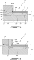
Fig. 4 is a schematic cross-sectional view taken along line B-B ofFig. 2 in accordance with one embodiment; -
Fig. 5 is a schematic cross-sectional view taken along line A-A ofFig. 2 in accordance with the embodiment ofFig. 4 ; -
Fig. 6 is a schematic cross-sectional view taken along line B-B ofFig. 2 in accordance with another embodiment; -
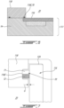
Fig. 7 is an enlarged view of a portion ofFig. 6 ; -
Fig. 8 is a top view of a seal for the housing ofFig. 7 ; -
Fig. 9 is a cross-sectional view of the seal ofFig. 8 taken along line 9-9 onFig. 8 ; and -
Fig. 10 is a flowchart illustrating steps of a method of sealing a rotor cavity of the rotary internal combustion engine ofFig. 1 . - Referring to
Fig. 1 , a rotary internal combustion engine, referred to simply as arotary engine 10 below, which may be a Wankel engine, is schematically shown. Therotary engine 10 comprises an outer body also referred to as ahousing assembly 12 having axially-spacedside housings 11, which each includes aside wall 14 and aside plate 16 mounted to theside wall 14, with arotor housing 18 extending from one of theside housings 11 to the other, to form arotor cavity 20. Therotor cavity 20 is defined axially between theside housings 11 and circumscribed by therotor housing 18. InFig. 1 , theside wall 14 is indicated with a dashed line because it sits below theside plate 16. The inner surface of therotor housing 18 has a profile defining two lobes, which may be an epitrochoid. In some alternate embodiments, theside housings 11 include solely the side wall, that is, the side wall and the side plate may be combined into a single element. - The
housing assembly 12 includes acoolant circuit 12A, which may include a plurality ofcoolant conduits 18B defined within therotor housing 18. As shown more clearly inFig. 5 , thecoolant conduits 18B extends from one of theside housings 11 to the other. Thecoolant circuit 12A is used for circulating a coolant, such as water or any suitable coolant, to cool thehousing assembly 12 during operation of therotary engine 10. Although only twocoolant conduits 18B are shown, it is understood that more than twocoolant conduits 18B may be used without departing from the scope of the present disclosure. - An inner body or
rotor 24 is received within therotor cavity 20. Therotor 24 has axially spaced end faces 26 adjacent to theside walls 14, and aperipheral face 28 extending therebetween. Theperipheral face 28 defines three circumferentially-spacedapex portions 30, and a generally triangular profile with outwardlyarched sides 36. Theapex portions 30 are in sealing engagement with the inner surface ofrotor housing 18 to form three rotatingcombustion chambers 32 between therotor 24 andhousing assembly 12. Thecombustion chambers 32 vary in volume with rotation of therotor 24 within thehousing assembly 12. The geometrical axis of therotor 24 is offset from and parallel to the axis of thehousing assembly 12. In some embodiments, more or less than three rotating combustion chambers may be provided with other shapes of the rotor. - The
combustion chambers 32 are sealed. In the embodiment shown, eachrotor apex portion 30 has anapex seal 52 extending from oneend face 26 to the other and biased radially outwardly against therotor housing 18. Anend seal 54 engages each end of eachapex seal 52 and is biased against therespective side wall 14. Eachend face 26 of therotor 24 has at least one arc-shaped face seal 60 running from eachapex portion 30 to eachadjacent apex portion 30, adjacent to but inwardly of the rotor periphery throughout its length, in sealing engagement with theend seal 54 adjacent each end thereof and biased into sealing engagement with theadjacent side plates 16 of theside housings 11. Alternate sealing arrangements are also possible. - Although not shown in the Figures, the
rotor 24 is journaled on an eccentric portion of a shaft such that the shaft rotates therotor 24 to perform orbital revolutions within therotor cavity 20. The shaft may rotate three times for each complete rotation of therotor 24 as it moves around therotor cavity 20. Oil seals are provided around the eccentric to impede leakage flow of lubricating oil radially outwardly thereof between the respectiverotor end face 26 and side housings 11. During each rotation of therotor 24, eachchamber 32 varies in volumes and moves around therotor cavity 20 to undergo the four phases of intake, compression, expansion and exhaust, these phases being similar to the strokes in a reciprocating-type internal combustion engine having a four-stroke cycle. - The engine includes a
primary inlet port 40 in communication with a source of air and anexhaust port 44 In the embodiment shown, theports rotor housing 18. Alternate configurations are possible. - In a particular embodiment, fuel such as kerosene (jet fuel) or other suitable fuel is delivered into the
chamber 32 through a fuel port (not shown) such that thechamber 32 is stratified with a rich fuel-air mixture near the ignition source and a leaner mixture elsewhere, and the fuel-air mixture may be ignited within the housing using any suitable ignition system known in the art (e.g. spark plug, glow plug). In a particular embodiment, therotary engine 10 operates under the principle of the Miller or Atkinson cycle, with its compression ratio lower than its expansion ratio, through appropriate relative location of theprimary inlet port 40 andexhaust port 44. - Referring now to
Figs. 2-5 , one of twoside housings 11 of thehousing assembly 12 is illustrated. As briefly introduced above, theside housings 11 include theside walls 14 that are secured to therotor housing 18. Each of theside walls 14 has a portion located proximate an outer perimeter P (Fig. 4 ) of theside wall 14 and configured to be in abutment against therotor housing 18 for defining therotor cavity 20. - In the embodiment shown, each of the
side walls 14 is configured to be secured to a respective one of opposed ends of therotor housing 18. The side housings 11 further includeside plates 16 located on inner sides of theside walls 14. Theside plates 16 define rotor-engagingfaces 16A on which the side seals 60 and the corner seals 54 of therotor 24 are in abutment during rotation of therotor 24. Theside plates 16 further define back faces opposite the rotor-engagingfaces 16A. The back faces of theside plates 16 face theside walls 14. - The
side walls 14 may be made of aluminum, more specifically an aluminum alloy, due to its light weight and high thermal conductivity. However, it may be required that the surfaces of theside walls 14 in contact with theseals side plates 16 are made of aluminum and coated with a hard material such as silicon carbide, aluminum nitride, chromium carbide, tungsten carbide, and so on. Any suitable wear resistant coating applied by thermal spray or any other suitable method may be used. Theside walls 14 and theside plates 16 will be described in more details below. Although the text below uses the singular form, the description may be applied to both of theside walls 14 and to both of theside plates 16. Theside plates 16 may however be entirely made of the hard material, such as silicon carbide. Theside plates 16 may be made of aluminum, steal, or any suitable ceramic. - Referring more particularly to
Fig. 4 , theside wall 14 includes aperipheral section 14A, which is in abutment with therotor housing 18, and acenter section 14B, which is circumferentially surrounded by theperipheral section 14A. In the disclosed embodiment, theperipheral section 14A of theside wall 14 is secured to therotor housing 18. Thecenter section 14B of one of theside walls 14 faces thecenter section 14B of the other of theside walls 14. Theside walls 14 are secured to therotor housing 18 with any suitable means known in the art. As shown, a sealingmember 19 is located between therotor housing 18 and theperipheral sections 14A of theside walls 14 for limiting coolant and combustion gases from leaking out. The sealingmember 19 may be an O-ring. The sealingmember 19 may be received within an annular recess, which may be defined by one or more of therotor housing 18 and theside wall 14. - The
side wall 14 defines arecess 14C for receiving theside plate 16. Theperipheral section 14A of theside wall 14 extends from the outer perimeter P to therecess 14C. As shown, asurface 14D of theperipheral section 14A of theside wall 14 that faces therotor housing 18 is axially offset from asurface 14E of thecenter section 14B of theside wall 14. A magnitude of the offset corresponds to a depth of therecess 14C and may correspond to a thickness t of theside plate 16 plus any axial gap defined between a rotor-engaging face of theside plate 16 and therotor housing 18. Theside plate 16 is therefore in abutment with thesurface 14E of thecenter section 14B of theside wall 14. In other words, a sealing surface of theside plate 16, located on a side of theside plate 16 that faces the rotor cavity, may be aligned with theperipheral section 14A of theside wall 14. - The
side wall 14 defines anabutment surface 14F. Theabutment surface 14F is defined by a shoulder created by the offset of thesurfaces central sections side wall 14. Theside wall 14, via itsabutment surface 14F, limits radial movements of theside plate 16 relative to the axis of rotation of therotor 24. Theside plate 16 may be supported by a housing in the center to limit the movement of theside plate 16. - In a particular embodiment, a gap may remain between a peripheral section of the
side plate 16 and theabutment surface 14F of theside wall 14. In other words, and in the embodiment shown, theside plate 16 may be spaced apart from theabutment surface 14F. A size of the gap may change during operation of therotary engine 10 as theside wall 14 and theside plate 16 may expand at different rates with an increase of a temperature in therotor cavity 20. In other words, the space between theside plate 16 and theabutment surface 14F of theside wall 14 may allow relative thermal expansion between theside plate 16 and theside wall 14 so that thermal stress transferred from theside plate 16 to therotor housing 18 and theside wall 14 might be minimized. - To limit axial movements of the
side plate 16 relative to the axis of rotation of the rotor 24 (Fig. 1 ), a periphery of theside plate 16 is contained axially between therotor housing 18 and theside wall 14. In other words, the periphery of theside plate 16 is sandwiched between theside wall 14 and therotor housing 18. Aseal 70 is located at the periphery of theside plate 16 for limiting the combustion gases to leak out of therotor cavity 20 and for limiting the cooling fluid from leaking into the combustion chamber 32 (Fig. 1 ). As shown more specifically inFigs. 4-5 , theseal 70 is contained within agroove 16B defined by theside plate 16. Theseal 70 is described in detail below. - In a particular embodiment, the
seal 70 and theabutment surface 14F of theside wall 14 allows theside plate 16 to move radially relative to theside wall 14. Such a movement, along a radial direction relative to the axis of rotation of therotor 24, may be required in a configuration in which theside wall 14 is made of a material having a coefficient of thermal expansion different than that of theside plate 16 and/or because the different components may be exposed to different temperatures and, thus may exhibit different thermal expansion. - The
side wall 14 further defines apocket 14G that may circumferentially extend a full circumference of theside wall 14. In other words, thepocket 14G is annular. More than one pocket may be used. Thepocket 14G may not cover an entirety of thecenter section 14B of theside wall 14. Thepocket 14G is configured for circulating a liquid coolant, such as water for cooling theside plate 16. Thepocket 14G may be part of thecoolant circuit 12A and is in fluid flow communication with thecoolant conduits 18B that are defined in therotor housing 18. Thepocket 14G extends from thesurface 14E of thecenter section 14B and away from therotor cavity 20. A depth D (Fig. 5 ) of thepocket 14G is defined by a distance along the axis of rotation of therotor 24 between thesurface 14E of thecenter section 14B and abottom surface 14H of thepocket 14G. - As shown in
Figs. 2-3 , theperipheral section 14A of theside wall 14 defines a plurality of ribs 14I that are circumferentially distributed around therotor cavity 20. The ribs 14I defines theabutment surface 14F and a portion of thesurface 14E of thecenter section 14B of theside wall 14. Consequently, and in the depicted embodiment, theabutment surface 14F is defined by a plurality of surfaces defined by the ribs 14I. The ribs 14I may be configured to support a pressure load imparted by a combustion of a mixture of air and fuel within thecombustion chambers 32. - Cavities or
spaces 14J are defined between the ribs 14I. More specifically, each pair of two consecutive ones of the ribs 14I defines aspace 14J therebetween. Thespaces 14J are in fluid communication with thepocket 14G and with thecoolant conduits 18B of therotor housing 18. Stated otherwise, thecoolant conduits 18B are in fluid communication with thepocket 14G via thespaces 14J between the ribs 14I. Thespaces 14J may allow the liquid coolant to flow from thepocket 14G to thecoolant conduits 18B of therotor housing 18. It is understood that the liquid coolant may be circulated in closed loop and through a heat exchanger. The heat exchanger may be used to dissipate heat to an environment outside the engine; the heat transferred from the engine to the liquid coolant. - As shown in
Figs. 2 and5 , a flow F1 of the liquid coolant circulates within thepocket 14G. The flow F1 is divided in sub-flows F2; each of the sub-flows F2 circulating within a respective one of thespaces 14J and within a respective one of thecoolant conduits 18B of thecoolant circuit 12A. The liquid coolant may be circulated out of thehousing assembly 12 and within a heat exchanger for extracting the heat. The liquid coolant may then be reinjected in thecoolant circuit 12A for further heat extraction. - Referring now to
Fig. 6 , another embodiment of the outer body, more specifically of theside housing 111 androtor housing 118, is generally shown. For the sake of conciseness, only elements that differ from thehousing assembly 12 ofFigs. 2-5 are described. In the embodiment shown, therotor housing 118 defines agroove 118C that receives theseal 70. - The description below refers more particularly to the embodiment of
Fig. 7 in which therotor housing 118 defines a groove annularly extending around the axis of thehousing assembly 12. It will however be appreciated that the principles of the present disclosure apply equally to the embodiment ofFig. 4 in which theseal 70 is received within a recess or a groove defined by theside plate 116. In some embodiments, theseal 70 maybe received within a groove or recess defined conjointly by both therotor housing 18 and theside plate 116. Theseal 70 may thus be located outwardly of the inner face of therotor housing 18 and overlaps a peripheral section of theside housing 111. This peripheral section corresponds to the section of theside housing 111 orside plate 116 that is overlapped by therotor housing 118. Herein, since theside housing 111 includes aside wall 14 secured to therotor housing 118 and aside plate 116, the peripheral section corresponds to a section of theside plate 116 that is dispose axially between, or sandwiched, between therotor housing 118 and theside wall 14. - Referring now to
Fig. 7 , theseal 70 is used to prevent leakage of the combustion gases out of therotor cavity 20 and to prevent the liquid coolant from leaking out of thecoolant circuit 12A. However, there is a gap G defined axially between theside plate 116 and therotor housing 118. This gap G is present to ensure that theside plate 116 is not within the engine clamping stack and thus to avoid transmitting axial load generated by fastening therotor housing 118 to the side housings 111. The coolant flowing within thecoolant circuit 12A is used to maintain the metal temperatures around theseal 70 within an acceptable level. However, in the embodiment shown, the gap G has a dimension of about 0.004" ± 0.0007 (0.1 mm ± 0.02mm). Other dimensions are contemplated. The gap G is sized to reduce the loading of theside plates 116 due to thermal expansions. As a result, the gap G may remain open at some circumferential locations during operation of the engine. This may allow hot combustion gases to impinge on theseal 70. Theseal 70 of the present disclosure may be designed to withstand these harsh operating conditions. Theseal 70 may adequately seal therotor cavity 20 from thecoolant circuit 12A and limit axial clamping load on theside plates 116 to less than 5000 lbs (20kN). - In the embodiment shown, the
seal 70 is a composite seal including anelastomeric member 71 and ashield 72. Theelastomeric member 71 is compressed between the peripheral section of theside housing 111 and therotor housing 118. More specifically, theelastomeric member 71 is compressed between the peripheral section of theside plate 116 and therotor housing 118, herein within thegroove 118C. Theelastomeric member 71 may be made of any suitable material such as, for instance, Viton™, silicone, perfluoroelastomer, fluorocarbon-based fluoroelastomer, and so on. - The
shield 72 is disposed inwardly of theelastomeric member 71 relative to the axis of rotation of the rotor 24 (Fig. 1 ). Theelastomeric member 71 is therefore located radially between the inner face of therotor housing 118 and theshield 72; the inner face of therotor housing 118 being in sealing contact with therotor 24. Theshield 72 is in contact with both of the peripheral section of theside housing 111 and therotor housing 118, herein in contact with both of therotor housing 118 within thegroove 118C and with theside plate 116. Theshield 72 contacts both of therotor housing 118 and theside plate 116 and may be compressed therebetween. Theshield 72 has a melting point above a temperature of combustion gases inside therotor cavity 20. Thus, theshield 72 may be able to protect theelastomeric member 71 from impingement with hot combustion gases exiting therotor cavity 20 via the gap G. - Referring to
Fig. 8 , theseal 70 may have a substantially round shape when not received in thegroove 118C of therotor housing 118. However, thisgroove 118C typically extends annularly all around therotor cavity 20 and may have a shape matching that of thehousing assembly 12. Thus, theseal 70 may have an epitrochoid shape when inserted into thegroove 118C. As illustrated, theelastomeric member 71 is disposed radially outwardly of theshield 72. Theshield 72 axially overlaps an entirety of theelastomeric member 71 to avoid leaving exposed a portion of theelastomeric member 71. Theelastomeric member 71 and theshield 72 axially overlap one another relative to a central axis thereof. Both of theelastomeric member 71 and theshield 72 may be continuous along a full circumference. However, in some embodiments, theelastomeric member 71 and/or theshield 72 may include a plurality of shield segments circumferentially distributed and secured to one another. - Referring more particularly to
Fig. 9 , theshield 72 is herein made of braidedfibers 73. These braidedfibers 73 may be ceramic fibers, glass fibers, alumina-silica ceramic fibers, or any suitable fibers able to withstands the hot combustion gases of therotary engine 10. Theshield 72 definesvoids 74 between thebraided fibers 73. In some embodiments, thevoids 74 may be at least partially filled (e.g., pre-saturated) with a powder (e.g., graphite powder), to provide an improved sealing. The powder may thus fill the voids or pores of the braidedfibers 73. Theshield 72 may therefore be porous. However, a ratio of a volume occupied by the fibers by a total volume of theshield 72 may be greater than 0.5, preferably greater than 0.9. Thebraided fibers 73 may thus be densely packed so as to impede the combustion gases from reaching theelastomeric member 71. In some cases, a network of thevoids 74 and braidedfibers 73 may create tortuous flow paths through theshield 72. The combustion gases may flow slowly through theshield 72 while being cooled by the housing of therotary engine 10, which is itself liquid cooled. Thus, even if the combustion gases were to reach theelastomeric member 71, a temperature of those combustion gases as they contact theelastomeric member 71 may be below a melting point of theelastomeric member 71 since they have been cooled by the liquid-cooled housing through their passage in the tortuous flow paths around thebraided fibers 73. - In the disclosed embodiment, the
shield 72 and theelastomeric member 71 may be co-bonded. In other words, theseal 70 may have ahybrid section 75 in which theshield 72 and theelastomeric member 71 radially overlap one another relative to the central axis of theseal 70. In thishybrid section 75, thevoids 74 defined between thebraided fibers 73 may be at least partially filled or impregnated with a material of theelastomeric member 71. In an alternate embodiment, theshield 72 and theelastomeric member 71 may be glued to one another or secured to one another using any suitable means. - The
seal 70 has a quadrilateral (e.g., square, rectangular) cross-section. In some embodiments, theseal 70 has a circular cross-section including a core including the elastomeric member, and an outer shield surrounding the core. Thus, the elastomeric member and the outer shield may be concentric when seen in a cross-section on a plane containing a central axis of theseal 70. This may increase a contact area between both of theelastomeric member 71 and theshield 72 with therotor housing 118 and theside plate 116 compared to a configuration in which theseal 70 is round. This may, in turn, improve a sealing provided by theseal 70. However, other shapes are contemplated such as round, ellipsoid, and so on. The quadrilateral cross-section may also facilitate the manufacturing of theseal 70 via co-bonding as described above. Theseal 70 is suitably dimensioned so that both theelastomeric member 71 and theshield 72 remain in contact with both of therotor housing 118 andside plate 116 during operation of therotary engine 10 and to fit within thegroove 118C, which may have a depth of about 0.130" (3.30mm). - In an alternate embodiment, the shield may be a E-seal, a W-seal, or any other suitable metallic seal made of a material able to withstand the harsh temperatures of the combustion gases. This material may be, for instance, Inconel™ or Titanium. These metallic seals may not be able to provide sufficient sealing, thus the use of the elastomeric material. However, if a metallic seal were able to provide adequate sealing, it may also exert too high of an axial load on the
side plate 116, which is undesirable. - Referring now to
Fig. 10 , a method of sealing therotor cavity 20 is shown at 1000. Themethod 1000 includes preventing combustion gases from leaking out of therotor cavity 20 with theelastomeric member 71 disposed between therotor housing 118 and theside housing 111 secured to therotor housing 118 at 1002; and protecting theelastomeric member 71 from the combustion gases with theshield 72 disposed inwardly of theelastomeric member 71 at 1004. Theshield 72 has a melting point above a temperature of the combustion gases. - In the embodiment shown, the protecting of the
elastomeric member 71 from the combustion gases with theshield 72 includes protecting theelastomeric member 71 with theshield 72 including the braidedfibers 73 being co-bonded with theelastomeric member 71. - In the context of the present disclosure, the expression "about" implies variations of plus or minus 10%.
- The embodiments described in this document provide non-limiting examples of possible implementations of the present technology. Upon review of the present disclosure, a person of ordinary skill in the art will recognize that changes may be made to the embodiments described herein without departing from the scope of the present technology. Yet further modifications could be implemented by a person of ordinary skill in the art in view of the present disclosure, which modifications would be within the scope of the present technology.
Claims (12)
- A housing assembly (12) for a rotary internal combustion engine, comprising:a rotor housing (18; 118) circumferentially extending around an axis, the rotor housing (18; 118) having an inner face facing a rotor cavity (20);side housings (11; 111) each secured to a respective one of opposite sides of the rotor housing (18; 118), the rotor cavity (20) bounded axially between the side housings (11; 111); anda seal (70) received within a groove (16B; 118C) at an interface between the rotor housing (18; 118) and a first side housing of the side housings (11; 111), the groove (16B; 118C) annularly extending around the axis, located outwardly of the inner face of the rotor housing (18; 118), and overlapping a peripheral section (14A) of the first side housing of the side housings (11; 111), the seal (70) having:an elastomeric member (71) compressed between the peripheral section (14A) of the first side housing and the rotor housing (18; 118); anda shield (72) disposed inwardly of the elastomeric member (71) relative to the axis, the shield (72) having a melting point above a temperature of combustion gases inside the rotor cavity (20), the shield (72) in contact with both of the peripheral section (14A) of the first side housing and the rotor housing (18; 118).
- The housing assembly (12) of claim 1, wherein the shield (72) is made of braided fibers (73).
- The housing assembly (12) of claim 2, wherein the braided fibers (73) are braided ceramic fibers.
- The housing assembly (12) of claim 3, wherein the braided ceramic fibers are braided alumina-silica fibers.
- The housing assembly (12) of claim 2, 3 or 4, wherein the shield (72) includes voids (74) between the braided fibers (73), the elastomeric member (71) and the shield (72) being co-bonded, the voids (74) within a section of the shield (72) filled with a material of a section of the elastomeric member (71).
- The housing assembly (12) of any preceding claim, wherein the seal (70) has a quadrilateral cross-section.
- The housing assembly (12) of any preceding claim, comprising a coolant circuit (12A) within the rotor housing (18; 118) and the side housing (11; 111) assemblies, the seal (70) fluidly separating the coolant circuit (12A) from the rotor cavity (20).
- The housing assembly (12) of any preceding claim, wherein the first side housing includes a side wall (14) secured to the rotor housing (18; 118) and a side plate (16; 116), a peripheral section (14A) of the side plate (16; 116) disposed between the side wall (14) and the rotor housing (18; 118).
- The housing assembly (12) of claim 8, wherein a gap (G) is defined between the rotor housing (18; 118) and the peripheral section (14A) of the side plate (16; 116), the groove (16B; 118C) communicating with the rotor cavity (20) through the gap (G).
- A rotary internal combustion engine (10) comprising:the housing assembly (12) according to any preceding claim; anda rotor (24) received in the rotor cavity (20).
- A method of sealing a rotor cavity (20) of a rotary internal combustion engine (10), comprising:preventing combustion gases from leaking out of the rotor cavity (20) with an elastomeric member (71) disposed between a rotor housing (18; 118) and a side housing (11; 111) secured to the rotor housing (18; 118); andprotecting the elastomeric member (71) from the combustion gases with a shield (72) disposed inwardly of the elastomeric member (71), the shield (72) having a melting point above a temperature of the combustion gases.
- The method of claim 11, wherein the protecting of the elastomeric member (71) from the combustion gases with the shield (72) includes protecting the elastomeric member (71) with the shield (72) including braided fibers (73) being co-bonded with the elastomeric member (71), the braided fibers (73) includes voids (74) therebetween, some of the voids (74) filled with a material of a section of the elastomeric member (71).
Applications Claiming Priority (1)
| Application Number | Priority Date | Filing Date | Title |
|---|---|---|---|
| US18/189,360 US12421912B2 (en) | 2023-03-24 | 2023-03-24 | Rotary engine with seal having elastomeric member and shield |
Publications (2)
| Publication Number | Publication Date |
|---|---|
| EP4435229A1 true EP4435229A1 (en) | 2024-09-25 |
| EP4435229B1 EP4435229B1 (en) | 2025-10-08 |
Family
ID=90468743
Family Applications (1)
| Application Number | Title | Priority Date | Filing Date |
|---|---|---|---|
| EP24165818.6A Active EP4435229B1 (en) | 2023-03-24 | 2024-03-25 | Rotary engine with seal having elastomeric member and shield |
Country Status (3)
| Country | Link |
|---|---|
| US (1) | US12421912B2 (en) |
| EP (1) | EP4435229B1 (en) |
| CA (1) | CA3232639A1 (en) |
Families Citing this family (1)
| Publication number | Priority date | Publication date | Assignee | Title |
|---|---|---|---|---|
| US12435661B1 (en) * | 2024-04-08 | 2025-10-07 | Pratt & Whitney Canada Corp. | Rotary engine with seal having shield and elastomeric member |
Citations (4)
| Publication number | Priority date | Publication date | Assignee | Title |
|---|---|---|---|---|
| US3695790A (en) * | 1971-05-24 | 1972-10-03 | Charles Jones | Housing sealing means for rotary engines |
| US3964843A (en) * | 1974-01-14 | 1976-06-22 | Toyo Kogyo Co., Ltd. | Seal means for rotary piston engine |
| DE102014017849A1 (en) * | 2014-12-02 | 2016-06-02 | Kkm Gmbh | Rotary piston engine |
| US20200200009A1 (en) * | 2018-12-20 | 2020-06-25 | Pratt & Whitney Canada Corp. | Rotary engine with housing having silicon carbide plate |
Family Cites Families (16)
| Publication number | Priority date | Publication date | Assignee | Title |
|---|---|---|---|---|
| US3725123A (en) * | 1970-12-21 | 1973-04-03 | Owens Corning Fiberglass Corp | Glass fiber reinforced elastomers |
| DE2150007A1 (en) * | 1971-10-07 | 1973-04-12 | Daimler Benz Ag | ROTARY PISTON COMBUSTION MACHINE IN PARTICULAR IN TROCHOID DESIGN |
| US3914499A (en) * | 1972-05-10 | 1975-10-21 | Owens Corning Fiberglass Corp | Fiber reinforced elastomers |
| JPS5641041Y2 (en) * | 1972-09-09 | 1981-09-25 | ||
| JPS52112008A (en) * | 1976-03-15 | 1977-09-20 | Mazda Motor Corp | Housing construction of rotary piston engine |
| JPS62228759A (en) * | 1986-03-28 | 1987-10-07 | Nippon Pillar Packing Co Ltd | Gland packing |
| GB2214996A (en) | 1988-02-16 | 1989-09-13 | Gen Connector Corp | Pressure actuated seal |
| US5499826A (en) * | 1993-06-18 | 1996-03-19 | Utex Industries, Inc. | Anti-extrusion lip seal |
| ATE529668T1 (en) * | 2005-03-11 | 2011-11-15 | Gates Corp | PRESSURE-ACTIVATED COUPLING OF A RELEASE LOCK |
| US7857576B2 (en) * | 2006-09-11 | 2010-12-28 | Pratt & Whitney Canada Corp. | Seal system for an interturbine duct within a gas turbine engine |
| US20140367602A1 (en) | 2013-06-12 | 2014-12-18 | Smith International, Inc. | Valve member with composite seal |
| US10088049B2 (en) * | 2014-05-06 | 2018-10-02 | United Technologies Corporation | Thermally protected seal assembly |
| KR102538899B1 (en) * | 2016-06-20 | 2023-06-01 | 삼성전기주식회사 | Capacitor Component |
| US10464267B2 (en) * | 2017-06-29 | 2019-11-05 | GM Global Technology Operations LLC | Continuous fiber lattice for reinforcing polymeric composites |
| WO2021144758A1 (en) * | 2020-01-15 | 2021-07-22 | 3M Innovative Properties Company | Thermal runaway barrier for a rechargeable electrical energy storage system |
| US20230332614A1 (en) * | 2020-08-28 | 2023-10-19 | Siemens Energy Global GmbH & Co. KG | Compressor rotor having seal assembly within hirth coupling |
-
2023
- 2023-03-24 US US18/189,360 patent/US12421912B2/en active Active
-
2024
- 2024-03-20 CA CA3232639A patent/CA3232639A1/en active Pending
- 2024-03-25 EP EP24165818.6A patent/EP4435229B1/en active Active
Patent Citations (4)
| Publication number | Priority date | Publication date | Assignee | Title |
|---|---|---|---|---|
| US3695790A (en) * | 1971-05-24 | 1972-10-03 | Charles Jones | Housing sealing means for rotary engines |
| US3964843A (en) * | 1974-01-14 | 1976-06-22 | Toyo Kogyo Co., Ltd. | Seal means for rotary piston engine |
| DE102014017849A1 (en) * | 2014-12-02 | 2016-06-02 | Kkm Gmbh | Rotary piston engine |
| US20200200009A1 (en) * | 2018-12-20 | 2020-06-25 | Pratt & Whitney Canada Corp. | Rotary engine with housing having silicon carbide plate |
Also Published As
| Publication number | Publication date |
|---|---|
| EP4435229B1 (en) | 2025-10-08 |
| CA3232639A1 (en) | 2025-06-25 |
| US20240318611A1 (en) | 2024-09-26 |
| US12421912B2 (en) | 2025-09-23 |
Similar Documents
| Publication | Publication Date | Title |
|---|---|---|
| EP3670833B1 (en) | Rotary engine with housing having silicon carbide plate | |
| US10247092B2 (en) | Rotary internal combustion engine with cooled insert | |
| US8221062B2 (en) | Device and system for reducing secondary air flow in a gas turbine | |
| US11761376B1 (en) | Side plate for rotary engine | |
| EP4435229B1 (en) | Rotary engine with seal having elastomeric member and shield | |
| GB2432630A (en) | Near-adiabatic internal combustion rotary engine | |
| US12196154B2 (en) | Rotary engine with seal having elastomeric and metallic members | |
| US12435661B1 (en) | Rotary engine with seal having shield and elastomeric member | |
| US12503975B1 (en) | Housing assembly for rotary engine and method of manufacturing thereof | |
| US3540815A (en) | Sealing means for rotary internal combustion engines | |
| US3980412A (en) | Casing seal means for a rotary piston engine | |
| US12203410B1 (en) | Housing assembly for rotary engine | |
| US12291991B1 (en) | Housing assembly for rotary engine | |
| US12110819B1 (en) | Side plate for rotary engine | |
| CA2782732C (en) | Gas seal arrangement for rotary internal combustion engine | |
| RU2511818C2 (en) | Device for radial gap sealing between turbine rotor and stator | |
| CA3258516A1 (en) | Housing assembly for rotary engine | |
| US3963387A (en) | Rotary engine with self-centering rotor gear | |
| JPS5916482Y2 (en) | Rotor structure of rotary piston engine | |
| EP2642069B1 (en) | Port for rotary internal combustion engine | |
| EP3058227A1 (en) | A 3 directional rotary seal for fluid handling machines |
Legal Events
| Date | Code | Title | Description |
|---|---|---|---|
| PUAI | Public reference made under article 153(3) epc to a published international application that has entered the european phase |
Free format text: ORIGINAL CODE: 0009012 |
|
| STAA | Information on the status of an ep patent application or granted ep patent |
Free format text: STATUS: THE APPLICATION HAS BEEN PUBLISHED |
|
| AK | Designated contracting states |
Kind code of ref document: A1 Designated state(s): AL AT BE BG CH CY CZ DE DK EE ES FI FR GB GR HR HU IE IS IT LI LT LU LV MC ME MK MT NL NO PL PT RO RS SE SI SK SM TR |
|
| STAA | Information on the status of an ep patent application or granted ep patent |
Free format text: STATUS: REQUEST FOR EXAMINATION WAS MADE |
|
| 17P | Request for examination filed |
Effective date: 20241129 |
|
| RBV | Designated contracting states (corrected) |
Designated state(s): AL AT BE BG CH CY CZ DE DK EE ES FI FR GB GR HR HU IE IS IT LI LT LU LV MC ME MK MT NL NO PL PT RO RS SE SI SK SM TR |
|
| GRAP | Despatch of communication of intention to grant a patent |
Free format text: ORIGINAL CODE: EPIDOSNIGR1 |
|
| STAA | Information on the status of an ep patent application or granted ep patent |
Free format text: STATUS: GRANT OF PATENT IS INTENDED |
|
| RIC1 | Information provided on ipc code assigned before grant |
Ipc: F16J 15/02 20060101ALI20250404BHEP Ipc: F01C 21/10 20060101ALI20250404BHEP Ipc: F01C 21/06 20060101ALI20250404BHEP Ipc: F01C 19/00 20060101ALI20250404BHEP Ipc: F01C 1/22 20060101AFI20250404BHEP |
|
| INTG | Intention to grant announced |
Effective date: 20250509 |
|
| GRAS | Grant fee paid |
Free format text: ORIGINAL CODE: EPIDOSNIGR3 |
|
| GRAA | (expected) grant |
Free format text: ORIGINAL CODE: 0009210 |
|
| STAA | Information on the status of an ep patent application or granted ep patent |
Free format text: STATUS: THE PATENT HAS BEEN GRANTED |
|
| AK | Designated contracting states |
Kind code of ref document: B1 Designated state(s): AL AT BE BG CH CY CZ DE DK EE ES FI FR GB GR HR HU IE IS IT LI LT LU LV MC ME MK MT NL NO PL PT RO RS SE SI SK SM TR |
|
| REG | Reference to a national code |
Ref country code: GB Ref legal event code: FG4D Ref country code: CH Ref legal event code: F10 Free format text: ST27 STATUS EVENT CODE: U-0-0-F10-F00 (AS PROVIDED BY THE NATIONAL OFFICE) Effective date: 20251008 |
|
| REG | Reference to a national code |
Ref country code: DE Ref legal event code: R096 Ref document number: 602024000835 Country of ref document: DE |
|
| REG | Reference to a national code |
Ref country code: IE Ref legal event code: FG4D |
|
| REG | Reference to a national code |
Ref country code: NL Ref legal event code: MP Effective date: 20251008 |
|
| REG | Reference to a national code |
Ref country code: AT Ref legal event code: MK05 Ref document number: 1844940 Country of ref document: AT Kind code of ref document: T Effective date: 20251008 |
|
| PG25 | Lapsed in a contracting state [announced via postgrant information from national office to epo] |
Ref country code: NL Free format text: LAPSE BECAUSE OF FAILURE TO SUBMIT A TRANSLATION OF THE DESCRIPTION OR TO PAY THE FEE WITHIN THE PRESCRIBED TIME-LIMIT Effective date: 20251008 |
|
| PG25 | Lapsed in a contracting state [announced via postgrant information from national office to epo] |
Ref country code: ES Free format text: LAPSE BECAUSE OF FAILURE TO SUBMIT A TRANSLATION OF THE DESCRIPTION OR TO PAY THE FEE WITHIN THE PRESCRIBED TIME-LIMIT Effective date: 20251008 |
|
| REG | Reference to a national code |
Ref country code: LT Ref legal event code: MG9D |
|
| PG25 | Lapsed in a contracting state [announced via postgrant information from national office to epo] |
Ref country code: NO Free format text: LAPSE BECAUSE OF FAILURE TO SUBMIT A TRANSLATION OF THE DESCRIPTION OR TO PAY THE FEE WITHIN THE PRESCRIBED TIME-LIMIT Effective date: 20260108 |
|
| PGFP | Annual fee paid to national office [announced via postgrant information from national office to epo] |
Ref country code: DE Payment date: 20260219 Year of fee payment: 3 |
|
| PG25 | Lapsed in a contracting state [announced via postgrant information from national office to epo] |
Ref country code: AT Free format text: LAPSE BECAUSE OF FAILURE TO SUBMIT A TRANSLATION OF THE DESCRIPTION OR TO PAY THE FEE WITHIN THE PRESCRIBED TIME-LIMIT Effective date: 20251008 Ref country code: HR Free format text: LAPSE BECAUSE OF FAILURE TO SUBMIT A TRANSLATION OF THE DESCRIPTION OR TO PAY THE FEE WITHIN THE PRESCRIBED TIME-LIMIT Effective date: 20251008 Ref country code: FI Free format text: LAPSE BECAUSE OF FAILURE TO SUBMIT A TRANSLATION OF THE DESCRIPTION OR TO PAY THE FEE WITHIN THE PRESCRIBED TIME-LIMIT Effective date: 20251008 |
|
| PG25 | Lapsed in a contracting state [announced via postgrant information from national office to epo] |
Ref country code: RS Free format text: LAPSE BECAUSE OF FAILURE TO SUBMIT A TRANSLATION OF THE DESCRIPTION OR TO PAY THE FEE WITHIN THE PRESCRIBED TIME-LIMIT Effective date: 20260108 |
|
| PG25 | Lapsed in a contracting state [announced via postgrant information from national office to epo] |
Ref country code: IS Free format text: LAPSE BECAUSE OF FAILURE TO SUBMIT A TRANSLATION OF THE DESCRIPTION OR TO PAY THE FEE WITHIN THE PRESCRIBED TIME-LIMIT Effective date: 20260208 |
|
| PGFP | Annual fee paid to national office [announced via postgrant information from national office to epo] |
Ref country code: FR Payment date: 20260219 Year of fee payment: 3 |
|
| PG25 | Lapsed in a contracting state [announced via postgrant information from national office to epo] |
Ref country code: PT Free format text: LAPSE BECAUSE OF FAILURE TO SUBMIT A TRANSLATION OF THE DESCRIPTION OR TO PAY THE FEE WITHIN THE PRESCRIBED TIME-LIMIT Effective date: 20260209 |
|
| PG25 | Lapsed in a contracting state [announced via postgrant information from national office to epo] |
Ref country code: PL Free format text: LAPSE BECAUSE OF FAILURE TO SUBMIT A TRANSLATION OF THE DESCRIPTION OR TO PAY THE FEE WITHIN THE PRESCRIBED TIME-LIMIT Effective date: 20251008 |
|
| PG25 | Lapsed in a contracting state [announced via postgrant information from national office to epo] |
Ref country code: LV Free format text: LAPSE BECAUSE OF FAILURE TO SUBMIT A TRANSLATION OF THE DESCRIPTION OR TO PAY THE FEE WITHIN THE PRESCRIBED TIME-LIMIT Effective date: 20251008 |
|
| PG25 | Lapsed in a contracting state [announced via postgrant information from national office to epo] |
Ref country code: BG Free format text: LAPSE BECAUSE OF FAILURE TO SUBMIT A TRANSLATION OF THE DESCRIPTION OR TO PAY THE FEE WITHIN THE PRESCRIBED TIME-LIMIT Effective date: 20251008 |
|
| PG25 | Lapsed in a contracting state [announced via postgrant information from national office to epo] |
Ref country code: LT Free format text: LAPSE BECAUSE OF FAILURE TO SUBMIT A TRANSLATION OF THE DESCRIPTION OR TO PAY THE FEE WITHIN THE PRESCRIBED TIME-LIMIT Effective date: 20251008 |
|
| PG25 | Lapsed in a contracting state [announced via postgrant information from national office to epo] |
Ref country code: SM Free format text: LAPSE BECAUSE OF FAILURE TO SUBMIT A TRANSLATION OF THE DESCRIPTION OR TO PAY THE FEE WITHIN THE PRESCRIBED TIME-LIMIT Effective date: 20251008 |
|
| PG25 | Lapsed in a contracting state [announced via postgrant information from national office to epo] |
Ref country code: DK Free format text: LAPSE BECAUSE OF FAILURE TO SUBMIT A TRANSLATION OF THE DESCRIPTION OR TO PAY THE FEE WITHIN THE PRESCRIBED TIME-LIMIT Effective date: 20251008 |
|
| PG25 | Lapsed in a contracting state [announced via postgrant information from national office to epo] |
Ref country code: IT Free format text: LAPSE BECAUSE OF FAILURE TO SUBMIT A TRANSLATION OF THE DESCRIPTION OR TO PAY THE FEE WITHIN THE PRESCRIBED TIME-LIMIT Effective date: 20251008 |
|
| PG25 | Lapsed in a contracting state [announced via postgrant information from national office to epo] |
Ref country code: EE Free format text: LAPSE BECAUSE OF FAILURE TO SUBMIT A TRANSLATION OF THE DESCRIPTION OR TO PAY THE FEE WITHIN THE PRESCRIBED TIME-LIMIT Effective date: 20251008 |
|
| PG25 | Lapsed in a contracting state [announced via postgrant information from national office to epo] |
Ref country code: CZ Free format text: LAPSE BECAUSE OF FAILURE TO SUBMIT A TRANSLATION OF THE DESCRIPTION OR TO PAY THE FEE WITHIN THE PRESCRIBED TIME-LIMIT Effective date: 20251008 |
|
| PG25 | Lapsed in a contracting state [announced via postgrant information from national office to epo] |
Ref country code: SK Free format text: LAPSE BECAUSE OF FAILURE TO SUBMIT A TRANSLATION OF THE DESCRIPTION OR TO PAY THE FEE WITHIN THE PRESCRIBED TIME-LIMIT Effective date: 20251008 |
|
| PG25 | Lapsed in a contracting state [announced via postgrant information from national office to epo] |
Ref country code: SE Free format text: LAPSE BECAUSE OF FAILURE TO SUBMIT A TRANSLATION OF THE DESCRIPTION OR TO PAY THE FEE WITHIN THE PRESCRIBED TIME-LIMIT Effective date: 20251008 |
|
| PLBE | No opposition filed within time limit |
Free format text: ORIGINAL CODE: 0009261 |
|
| STAA | Information on the status of an ep patent application or granted ep patent |
Free format text: STATUS: NO OPPOSITION FILED WITHIN TIME LIMIT |