EP4435228A1 - Methods for producing a geothermal well - Google Patents
Methods for producing a geothermal well Download PDFInfo
- Publication number
- EP4435228A1 EP4435228A1 EP23305387.5A EP23305387A EP4435228A1 EP 4435228 A1 EP4435228 A1 EP 4435228A1 EP 23305387 A EP23305387 A EP 23305387A EP 4435228 A1 EP4435228 A1 EP 4435228A1
- Authority
- EP
- European Patent Office
- Prior art keywords
- wellbore
- wellbores
- planned
- drilling
- model
- Prior art date
- Legal status (The legal status is an assumption and is not a legal conclusion. Google has not performed a legal analysis and makes no representation as to the accuracy of the status listed.)
- Granted
Links
Images





Classifications
-
- E—FIXED CONSTRUCTIONS
- E21—EARTH OR ROCK DRILLING; MINING
- E21B—EARTH OR ROCK DRILLING; OBTAINING OIL, GAS, WATER, SOLUBLE OR MELTABLE MATERIALS OR A SLURRY OF MINERALS FROM WELLS
- E21B47/00—Survey of boreholes or wells
- E21B47/02—Determining slope or direction
-
- E—FIXED CONSTRUCTIONS
- E21—EARTH OR ROCK DRILLING; MINING
- E21B—EARTH OR ROCK DRILLING; OBTAINING OIL, GAS, WATER, SOLUBLE OR MELTABLE MATERIALS OR A SLURRY OF MINERALS FROM WELLS
- E21B44/00—Automatic control systems specially adapted for drilling operations, i.e. self-operating systems which function to carry out or modify a drilling operation without intervention of a human operator, e.g. computer-controlled drilling systems; Systems specially adapted for monitoring a plurality of drilling variables or conditions
-
- E—FIXED CONSTRUCTIONS
- E21—EARTH OR ROCK DRILLING; MINING
- E21B—EARTH OR ROCK DRILLING; OBTAINING OIL, GAS, WATER, SOLUBLE OR MELTABLE MATERIALS OR A SLURRY OF MINERALS FROM WELLS
- E21B33/00—Sealing or packing boreholes or wells
- E21B33/02—Surface sealing or packing
- E21B33/03—Well heads; Setting-up thereof
- E21B33/04—Casing heads; Suspending casings or tubings in well heads
- E21B33/047—Casing heads; Suspending casings or tubings in well heads for plural tubing strings
-
- E—FIXED CONSTRUCTIONS
- E21—EARTH OR ROCK DRILLING; MINING
- E21B—EARTH OR ROCK DRILLING; OBTAINING OIL, GAS, WATER, SOLUBLE OR MELTABLE MATERIALS OR A SLURRY OF MINERALS FROM WELLS
- E21B41/00—Equipment or details not covered by groups E21B15/00 - E21B40/00
- E21B41/0035—Apparatus or methods for multilateral well technology, e.g. for the completion of or workover on wells with one or more lateral branches
-
- E—FIXED CONSTRUCTIONS
- E21—EARTH OR ROCK DRILLING; MINING
- E21B—EARTH OR ROCK DRILLING; OBTAINING OIL, GAS, WATER, SOLUBLE OR MELTABLE MATERIALS OR A SLURRY OF MINERALS FROM WELLS
- E21B7/00—Special methods or apparatus for drilling
- E21B7/04—Directional drilling
-
- F—MECHANICAL ENGINEERING; LIGHTING; HEATING; WEAPONS; BLASTING
- F24—HEATING; RANGES; VENTILATING
- F24T—GEOTHERMAL COLLECTORS; GEOTHERMAL SYSTEMS
- F24T10/00—Geothermal collectors
-
- E—FIXED CONSTRUCTIONS
- E21—EARTH OR ROCK DRILLING; MINING
- E21B—EARTH OR ROCK DRILLING; OBTAINING OIL, GAS, WATER, SOLUBLE OR MELTABLE MATERIALS OR A SLURRY OF MINERALS FROM WELLS
- E21B2200/00—Special features related to earth drilling for obtaining oil, gas or water
- E21B2200/20—Computer models or simulations, e.g. for reservoirs under production, drill bits
-
- F—MECHANICAL ENGINEERING; LIGHTING; HEATING; WEAPONS; BLASTING
- F24—HEATING; RANGES; VENTILATING
- F24T—GEOTHERMAL COLLECTORS; GEOTHERMAL SYSTEMS
- F24T10/00—Geothermal collectors
- F24T2010/50—Component parts, details or accessories
- F24T2010/53—Methods for installation
-
- Y—GENERAL TAGGING OF NEW TECHNOLOGICAL DEVELOPMENTS; GENERAL TAGGING OF CROSS-SECTIONAL TECHNOLOGIES SPANNING OVER SEVERAL SECTIONS OF THE IPC; TECHNICAL SUBJECTS COVERED BY FORMER USPC CROSS-REFERENCE ART COLLECTIONS [XRACs] AND DIGESTS
- Y02—TECHNOLOGIES OR APPLICATIONS FOR MITIGATION OR ADAPTATION AGAINST CLIMATE CHANGE
- Y02E—REDUCTION OF GREENHOUSE GAS [GHG] EMISSIONS, RELATED TO ENERGY GENERATION, TRANSMISSION OR DISTRIBUTION
- Y02E10/00—Energy generation through renewable energy sources
- Y02E10/10—Geothermal energy
Definitions
- Ground source heat pump systems are conventionally conceived with vertical wells that extend in depth from about 50 to 250 meters.
- the wells are positioned after estimating the total length required to cover all or a portion of a building thermal needs.
- crude approximations are often used, such as with the American Society of Heating, Refrigerating, and Air-Conditioning Engineers (ASHRAE) method: a simple equation provides the total drilled length of vertical wellbores as a function of the building thermal power needs at different time scales with a temperature penalty term linked to the thermal interactions between the wells and their spacings.
- ASHRAE American Society of Heating, Refrigerating, and Air-Conditioning Engineers
- a method of producing a geothermal well includes obtaining site information including at least a site volume; obtaining drilling parameters; determining a quantity of planned wellbores having a shared wellhead based at least partially on the site information and drilling parameters; determining orientations of the planned wellbores based at least partially on the site information, the drilling parameters, and the quantity of wellbores to position wellbores within boundaries of the site volume; determining lengths of the planned wellbores based at least partially on the site information, the drilling parameters, and the quantity of wellbores to position wellbores within boundaries of the site volume; and drilling at least a first wellbore of the planned wellbores based on a determined orientation and a determined length from the shared wellhead.
- a method of producing a geothermal well includes obtaining site information including at least a site volume; obtaining drilling parameters; determining a quantity of planned wellbores having a shared wellhead based at least partially on the site information and drilling parameters; determining orientations of the planned wellbores based at least partially on the site information, the drilling parameters, and the quantity of wellbores to position wellbores within boundaries of the site volume; determining lengths of the planned wellbores based at least partially on the site information, the drilling parameters, and the quantity of wellbores to position wellbores within boundaries of the site volume; drilling a first drilled wellbore of the planned wellbores based on a determined orientation and a determined length from the shared wellhead; measuring at least one wellbore property of the first drilled wellbore; recalculating orientations and lengths of remaining planned wellbores based at least partially on the at least one wellbore property of the first drilled wellbore; and drilling at least one drilled remaining wellbore of the remaining planned wellbores.
- a method of producing a geothermal well includes obtaining site information including at least a site volume; obtaining drilling parameters; determining a quantity of planned wellbores having a shared wellhead based at least partially on the site information and drilling parameters; determining orientations of the planned wellbores based at least partially on the site information, the drilling parameters, and the quantity of wellbores to position wellbores within boundaries of the site volume; determining lengths of the planned wellbores based at least partially on the site information, the drilling parameters, and the quantity of wellbores to position wellbores within boundaries of the site volume; drilling a first drilled wellbore of the planned wellbores based on a determined orientation and a determined length from the shared wellhead; measuring at least one wellbore property of the first drilled wellbore; recalculating orientations and lengths of remaining planned wellbores based at least partially on the at least one wellbore property of the first drilled wellbore; and drilling an additional wellbore based at least partially on a measured wellbore
- Embodiments of the present disclosure generally relate to devices, systems, and methods for planning and drilling a geothermal well. More specifically, embodiments of the present disclosure relate to calculating and drilling a geothermal well with an array of wellbores with the most efficient thermal recovery from the formation.
- Drilling a geothermal well allows the positioning of wellbore heat exchangers (BHEs) in the wellbores of the well.
- BHEs wellbore heat exchangers
- the BHEs transfer heat between a home, office, or other building primarily above ground with the geologic formation underground. Because the geologic formation remains substantially constant in temperature, the BHEs of the geothermal well can heat the building in colder temperatures above ground and cool the building in hotter temperatures above ground.
- the geothermal well can include a plurality of wellbores and a plurality of BHEs.
- Conventional geothermal wells include a plurality of vertical wellbores positioned throughout a field or area that allows each wellbore of the well to exchange heat with a different portion of the geological formation.
- drilling a plurality of wellbores from a plurality of locations requires moving the drilling equipment and managing a plurality of connections and contacts above ground.
- an array of wellbores can be located across a 100 meter (m) by 100m field, increasing drilling costs during creation of the geothermal well and maintenance costs over time of the geothermal well.
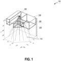
- FIG. 1 is a perspective view of a planned geothermal well 100 according to some embodiments of the present disclosure.
- the planned geothermal well 100 includes a plurality of planned wellbores 102 that each have at least an orientation and a length.
- the orientation is relative to the direction of gravity.
- the orientation is relative to a surface orientation, such as when the wellhead is located on a hillside.
- the surface orientation is substantially perpendicular to the direction of gravity, such that the orientation of the wellbore is substantially the same whether considered relative to the surface orientation or the direction of gravity.
- the planned geothermal well 100 is determined based at least partially on a variety of site constraints.
- the site constraints are determined from site information.
- the site information includes, but is not limited to, surface property limits 104, no-drill zones 106, maximum allowable depth 108, geothermal profile of the site, and other information.
- the surface property limits 104 e.g., property boundary
- the maximum allowable depth 108 define the outer bounds of a site volume in which wellbores 102 may be drilled.
- the site volume is further defined by no-drill zones 106, such as building foundations, drainage, storage tanks, wastewater tanks, other underground structures, and any applicable buffer areas around such underground structures.
- the site constraints further include a shared wellhead region 140 from which the wellbores 102 of the geothermal well 100 may originate at the surface.
- the site volume provides the volume in which wellbores may be drilled and/or positioned and, based at least partially on a geothermal profile, the thermal capacity available by a given planned geothermal well 100.
- the geothermal profile may be assumed to be a constant profile relative to the surface.
- the geothermal profile may be assumed to be a constant value throughout the site volume for initial calculations and/or drilling.
- the geothermal profile for the site volume is known from prior measurements or records.
- the geothermal profile is estimated from similar sites.
- the drilling of the wellbores is limited to an allowed drilling area.
- the allowed drilling area may be limited for legal reasons, such as property easements that allow access to the site, or for logistical reasons, such as access from a road or due to impassable terrains.
- an allowed drilling area on the surface defines a region of the surface from which the wellbores may be drilled.
- each of the wellbores may originate from a shared wellhead from which all of the wellbores may be drilled without substantially moving the drilling equipment.
- the planned geothermal well 100 may be further determined based at least partially on drilling constraints and/or drilling parameters, such as wellbore properties including a thermal transfer rate, a cost-per-meter for drilling a wellbore in the geological formation, a cost-per-start for each wellbore, a drilling rate, a maximum angle, a minimum wellbore length, a maximum wellbore length, a maximum well length (e.g., total length of the wellbores), minimum distance between wellbores, and other properties of the drilling and costs associated therewith.
- wellbore properties including a thermal transfer rate, a cost-per-meter for drilling a wellbore in the geological formation, a cost-per-start for each wellbore, a drilling rate, a maximum angle, a minimum wellbore length, a maximum wellbore length, a maximum well length (e.g., total length of the wellbores), minimum distance between wellbores, and other properties of the drilling and costs associated therewith.
- wellbore properties including
- drilling an additional 10 meters on 10 wellbores may cost less than drilling an 11 th wellbore with a length of 100 meters. However, based upon the site information and/or site constraints, drilling an additional 10 meters may not be possible without exceeding a maximum allowable depth.
- the planned geothermal well 100 is determined based at least partially on project constraints, which are high-level constraints on the planned geothermal well 100, such as the required total thermal capacity and a cost limit.
- FIG. 2 is a flowchart illustrating an embodiment of a method 210 of drilling a geothermal well.
- the method 210 includes obtaining site information including at least a site volume at 212.
- obtaining the site information includes accessing the site information from a local hardware storage device.
- a hardware storage device is any non-transient computer readable medium that may store instructions thereon.
- the hardware storage device may be any type of solid-state memory; volatile memory, such as static random access memory (SRAM) or dynamic random access memory (DRAM); non-volatile memory, such as read-only memory (ROM) including programmable ROM (PROM), erasable PROM (EPROM) or EEPROM; magnetic storage media, such as magnetic tape; a platen-based storage device, such as hard disk drives; optical media, such as compact discs (CD), digital video discs (DVD), Blu-ray Discs, or other optical media; removable media such as USB drives; non-removable media such as internal SATA or non-volatile memory express (NVMe) style NAND flash memory; or any other non-transient storage media.
- obtaining the site information includes accessing the site information from a remote storage device, such as a cloud storage device or server computer.
- the site information includes at least a site volume that is defined by a property limit and a maximum allowable depth.
- the site volume further includes no-drill zones that will limit the positioning of planned wellbores within the site volume.
- the site information includes a geothermal profile of the site. For example, different properties of the site may affect the geothermal properties, such as groundwater presence, formation composition, and other underground structures such as other pipes and wells.
- the site information further includes an allowed drilling area located at the surface of the site volume.
- the method 210 further includes obtaining drilling parameters at 214.
- the drilling parameter may include wellbore properties including a thermal transfer rate, a cost-per-meter for drilling a wellbore in the geological formation, a cost-per-start for each wellbore, a drilling rate, a maximum angle, a minimum wellbore length, a maximum wellbore length, a maximum well length (e.g., total length of the wellbores), minimum distance between wellbores, and other properties of the drilling and costs associated therewith.
- the drilling parameters allow a machine learning model or other model to determine the planned geothermal well when considered in context of the site information.
- the method 210 may include determining a quantity of planned wellbores at 216 before determining orientations of the planned wellbores at 218 and determining lengths of the planned wellbores at 220.
- determining the quantity of planned wellbores includes receiving a predetermined quantity of planned wellbores from an operator. For example, drilling constraints may limit the ability of a drilling team to produce the geothermal well, limiting the quantity of wellbores.
- the quantity of planned wellbores may be selected by an operator based on the cost of BHEs or other materials involved with the construction of the geothermal well and associated HVAC equipment. In such cases, the quantity of planned wellbores may be one of the drilling parameters obtained at 214.
- a machine learning model or other model iterates through a plurality of instances and/or nodes to determine the quantity of planned wellbores, as will be described in more detail herein.
- Determining the orientations and determining the lengths of the planned wellbores is based at least partially on the site information and the drilling parameters. For example, an orientation and length of the planned wellbore may be based at least partially on a maximum allowable depth of the site volume and/or a maximum angle of the wellbore relative to the surface. In some examples, the orientation and length of the planned wellbore may be based at least partially on the geothermal profile of the site volume, such as the temperature increasing proximate a lower region of the site volume or a presence of groundwater in the site volume limiting a length of the wellbore. Determining the quantity, orientation, and length of the planned wellbores of the geothermal well will be described in more detail herein.
- the method 210 further includes drilling at least a first wellbore of the planned wellbores at 222.
- the method 210 includes drilling all of the wellbores of the geothermal well.
- the method 210 includes drilling the first wellbore and using the first wellbore to obtain additional site information and/or drilling parameters to further refine the planned geothermal well and/or the planned wellbore(s). This operation is an optional configuration. In other configurations, the method may output the determined orientation and length, for instance for visualization by an user or as drilling instructions for drilling systems.
- determining the quantity, orientations, and lengths of the planned wellbores of the planned geothermal well includes using a machine learning model or other model with equality constraints and inequality constraints.
- the equality constraints include a total length of wellbores in the well, such as a constant L*.
- the equality constraints include a pre-determined or fixed quantity of wellheads, such as 1, 2, 3, 4, 5, or more. In most examples, the quantity of wellheads is a few or less, based on the site information and/or the logistics of accessing the allowable drilling areas.
- the inequality constraints are more flexible and may include a variety of conditions and properties, as long as a starting configuration can be found that satisfies them all.
- the inequality constraints include a maximum angle. For example, the inclination of a wellbore must be smaller than some maximum angle ⁇ ⁇ .
- an inequality constraint is that each wellbore must be longer than some minimal length l ⁇ .
- an inequality constraint is that all parts of a wellbore or the well must be within the site volume, where the site volume is defined by a maximum depth of D ⁇ (for example, 200 m) and a polygon in the x , y -plane, defining the property limits (e.g., boundary of the property).
- an inequality constraint is that two wellbores cannot be too close to each other, which may be determined by the model.
- constraints can easily be added while allowing the constraints to be evaluated in a reasonable period of time.
- additional constraints limit the search space, as new configurations may be attempted only if the configurations adhere to all the constraints.
- the model would be allowed to explore illegal configurations, but penalizing such configurations with a penalty proportional to the amount of the constraints that are broken. This penalty would then increase to a level where it would never be beneficial to the model to attempt illegal configurations which would lead to the same global optimum. However, this would enable to start in an illegal configuration to find a legal configuration.
- the model is an optimization model. It may, for instance, include a machine learning model.
- a "machine learning model” refers to a computer algorithm or model (e.g., a classification model, a regression model, a language model, an object detection model) that can be tuned (e.g., trained) based on training input to approximate unknown functions.
- an ML model may refer to a neural network or other machine learning algorithm or architecture that learns and approximates complex functions and generate outputs based on a plurality of inputs provided to the machine learning model.
- an ML system, model, or neural network described herein is an artificial neural network.
- an ML system, model, or neural network described herein is a convolutional neural network. In some embodiments, an ML system, model, or neural network described herein is a recurrent neural network. In at least one embodiment, an ML system, model, or neural network described herein is a Bayes classifier.
- a "machine learning system” may refer to one or multiple ML models that cooperatively generate one or more outputs based on corresponding inputs. For example, an ML system may refer to any system architecture having multiple discrete ML components that consider different kinds of information or inputs.
- the coordinates would also need to include a length r i of each wellbore.
- the value k i thus means that the wellbore i has the wellhead position ( x k i , y k i , z k i ) . If there is only one shared wellhead position where all wellbores start, this latter list is not necessary.
- z k is a predefined constant, meaning that also these coordinates are also essentially 2D, from a function optimization perspective.
- index i ⁇ that defines the index of a wellbore that adjusts its length to ensure that the total length of all wellbores is L* as per the equality constraint provided.
- each wellbore i may be constructed by starting at the wellhead position with index k i , and extend the wellbore in a straight line with inclination ⁇ i and azimuth ⁇ i until it intersects a boundary of the site volume, such as the maximum allowable depth D ⁇ or any side of the polygon that defines the property limits (whatever is closer).
- This length might or might not be acceptable for the planned geothermal well or wellbore(s). For example, the result may be negative or exceed the maximum depth.
- a set (X, W, M, i ⁇ ) describes a starting and end position of each wellbore, which means that it can be transformed into the necessary format of any function f ( Z ) needed.
- Z (X, W, M, i ⁇ ) allows consideration of the function f(X, W, M, i ⁇ ).
- a machine learning model, other model, or system of models according to the present disclosure operates on multiple lists in parallel, for example X and W.
- both are two-dimensional as the height z i of the wellhead position is a constant (set for instance to 0 or something slightly above ground to avoid a singularity if all wellbores meet at ground level).
- a model f(V) is an optimization model set to optimize one or more parameters of the system.
- a model f ( V ) s , where s is the thermal recovery score of the configuration V , operates to find a local maximum for s.
- the thermal recovery score which represents the efficiency of heat collection by the array of wellbores, is calculated in a negative value, wherein greater values (i.e., less negative values) reflect a more efficient recovery of thermal energy.
- Such optimization model may for instance include a function derived of a g-function, which represents the thermal resistance between the borehole and the ground.
- the model uses a negative g-function as the model intends to maximize the optimization function.
- optimization function may account for a penalty proportional to the amount of the constraints that are broken, in order to encourage the model to go to legal configurations.
- a method further includes defining a radius r that defines the search radius, and a function legal ( V ) , that returns True if the configuration adheres to all constraints, and False otherwise.
- V legal
- the constraints are taken into account in the optimization function and the use of legal(V) may be optional.
- the function provides a planned geothermal well with a plurality of wellbores by initializing the model according to the following example.
- generating the list V includes generating V randomly until a legal configuration is found by chance.
- the list V is predetermined by a user or operator for an initial V that is known to be legal.
- the method then replaces V by V ( j ) .
- the method upon exhaustion of all variations to v i without improvement to the value(s) of V, the method includes decreasing r with a factor ⁇ so that r ⁇ ⁇ ⁇ r, where 0 ⁇ ⁇ ⁇ 1. In some embodiments, when r ⁇ r ⁇ , the method or model stops.
- the method may stop upon completion of other criteria, such as number of iterations without improvement of the optimization function score, fixed number of iterations, etc.
- a model according to at least one embodiment described herein was initialized according to the following initialization values.
- Total length for all wellbores: L* 1800.
- Minimum length of a wellbore: l ⁇ 50.
- Maximum angle of a wellbore: ⁇ ⁇ 20°.
- Maximum allowable depth: D* 200.
- An evaluation of any well according to the present disclosure is performed, according to at least some embodiments, using a function f ( X, i ⁇ ) that acts as a heuristic for optimizing how much geothermal energy can be extracted from the ground.
- a function f ( X, i ⁇ ) that acts as a heuristic for optimizing how much geothermal energy can be extracted from the ground.
- the model allows a wellbore or wellbores shorter than l*, but the machine learning model or other model adds a penalty proportional to ( l ⁇ - l min ) to the optimization model if the shortest well is shorter than l ⁇ . Therefore, the model can evaluate and learn from non-compliant wellbore lengths but will be discouraged from accepting or will not accept a final solution if any well is shorter than l ⁇ .
- v i each well position.
- the radius r was initialized at 32°, and the optimization ends when r ⁇ 0.1°.
- the machine learning model or other model updates i ⁇ through a plurality of values.
- the machine learning model or other model defines i ⁇ to be the value that provided the better results.
- an array of 11 wellbores was determined to be the lowest (best) value.
- an array with too few wells, such as 9 results in all wells needing to be as long as possible in order to meet the prescribed total length of 1800m. This forces the wells to be closer than optimal to each other which makes their regions of heat exchange overlap more.
- an array with too many wells, such as 14 results in all wells needing to be as short as possible in order to meet the total length constraint. This again creates unnecessary overlap of the heat exchange regions of the wells while further leaving the bottom region of the site volume unexploited.
- FIG. 4 is a flowchart 426 illustrating the inputs of site information 428, drilling parameters 430, and project constraints 432 into the statistical model 434 as described in the above example.
- the model 434 then provides the values including at least azimuth and inclination angle of the planned wellbores 436 according to the lowest value calculated.
- the planned wellbores originate from approximately a single wellhead and fan out from the single wellhead.
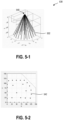
- FIG. 5-1 is a perspective view of an array 538 of planned wellbores 502 produced by the machine learning model or other model described in relation to FIG. 2 and FIG. 3 .
- the planned wellbores 502 originate from an approximate single wellhead 540 with the origin located at a height (z-value) above the surface to avoid a singularity.
- FIG. 5-1 is a perspective view of an array 538 of planned wellbores 502 produced by the machine learning model or other model described in relation to FIG. 2 and FIG. 3 .
- the planned wellbores 502 originate from an approximate single wellhead 540
- the downhole ends 542 of the planned wellbores at the lower portion of the site volume to distribute the wellbores throughout the site volume.
- the downhole ends form an arc segment when the wellbores are unobstructed by building foundations or other non-building zones.
- the building foundations or other non-building zones obstruct the wellbores and result in a linear arrangement of the downhole ends in the site volume according to the edge(s) of the building foundations or other non-building zones.
- the shared wellhead is not a single wellhead, but rather a region of allowable wellheads for the array of planned wellbores.
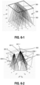
- FIG. 6-1 illustrates an embodiment of an array 638 of planned wellbores 602 with shared wellhead region 640 that runs the full length of a surface of the site volume. The planned wellbores then extend downward in a series of wellhead locations. Each wellhead location has a fan of planned wellbores 602 associated therewith. In such an example, the fans of planned wellbores are parallel to one another, where each fan defines a plane parallel to an adjacent plane. In some embodiments, a plurality of wellbores originates from a shared container at the surface.
- the array 638 includes a plurality of containers at the surface located in the wellhead region 640.
- the wellhead region 640 of FIG. 6-2 includes a plurality of wellpads 641-1, 641-2, 641-3 where each wellpad 641-1, 641-2, 641-3 in the shared wellhead region includes a subarray 638-1, 638-2, 638-3 of wellbores.
- a model according to the present disclosure calculates the position of one or more wellpads 641-1, 641-2, 641-3 and/or shared wellheads in the shared wellhead region 640 as explained above.
- FIG. 7 through FIG. 9 illustrate arrays of planned wellbores with associated thermal recovery scores for arrays of 9, 11, and 14 wellbores, respectively.
- FIG. 7 illustrates the output planned wellbores for an array of 9 wellbores.
- the machine learning model or other model produced a thermal recovery score of -12.4618 after 60 iterations of the model, as shown in the lefthand graph 744.
- the array of planned wellbores produced by the model required that all wells are as long as possible to achieve the required total length of 1800m selected during initialization of the model.
- the machine learning model or other model Upon achieving a consistent series of iterations with no improvement to the thermal recovery score (or improvement to the thermal recovery score less than a predetermined threshold value), the machine learning model or other model terminated and presented the results of the planned well shown in the center array 738 and the righthand bottom view of the wellbore ends 742 of FIG. 7 .
- the machine learning model or other model may increment the quantity of wellbores in the array by one and recalculate the array of planned wellbores.
- FIG. 8 illustrates the results of a model with an input of 11 wellbores for the calculated array of planned wellbores.
- the machine learning model or other model produced a thermal recovery score of -11.9575 after 100 iterations of the model, as shown in the lefthand graph 844.
- the array of planned wellbores produced by the model allowed a variety of wellbore lengths to achieve the total length of 1800m selected during initialization of the model.
- the machine learning model or other model Upon achieving a consistent series of iterations with no improvement to the thermal recovery score (or improvement to the thermal recovery score less than a predetermined threshold value), the machine learning model or other model terminated and presented the results of the planned well shown in the center array 838 and the righthand bottom view of the wellbore ends 842 of FIG. 8 .
- FIG. 9 illustrates the result of the model with an input of 13 wellbores for the calculated array of planned wellbores, which results in a more negative (i.e., worse) thermal recovery score than the 11-wellbore solution described in relation to FIG. 8 .
- the machine learning model or other model produced a thermal recovery score of -13.4458 after 140 iterations of the model, as shown in the lefthand graph 944.
- the array of planned wellbores produced by the model required the wellbore lengths to be truncated (which forces the wellbores closer to one another and reduces thermal recovery efficiency) to achieve the total length of 1800m selected during initialization of the model.
- the minimum length of a planned wellbore in the 13-wellbore array is 49 meters compared to 114 meters in the 11-wellbore array and 178 meters in the 9-wellbore array.
- the machine learning model or other model terminated and presented the results of the planned well shown in the center array 938 and the righthand bottom view of the wellbore ends 942 of FIG. 9 .
- a well placement model such as any of the statistical models and/or machine learning models described herein, is included in a statistical system or model that considers additional constraints or requirements.
- the additional constraints or requirements include, but are not limited to, a building thermal demand over a given period of time (e.g., "lifetime") such as 25 years; the surface equipment space requirements; the surface equipment cost(s); the ground thermal properties such as thermal conductivity, thermal capacity, undisturbed temperatures relative to depth, presence of aquifers; and other constraints or requirements.
- the well placement model calculates the minimum total length of wellbore in the well to be drilled to meet the additional constraints or requirements. In some embodiments, the well placement model calculates the greatest thermal recovery score based on a maximum allowed total cost of drilling the well and installing borehole heat exchanger. In some embodiments, the well placement model calculates the greatest thermal recovery score based on a maximum allowed total cost of drilling the well and of installing and operating borehole heat exchanger over the lifetime of the geothermal well.
- the cost function 1054 may be any function that defines the cost to start a wellbore, the cost-per-meter of a wellbore, the cost of operating the well, the cost relative to inclination or orientation of the wellbore(s), the cost relative to depth of the wellbore(s), the cost for surface equipment or construction (e.g., ditches and/or connections), the cost of subsurface equipment (e.g., borehole heat exchanger), costs offset by thermal recovery, or other costs associated with the creation or operation of the wellbore.
- the cost function 1054 may be any function that defines the cost to start a wellbore, the cost-per-meter of a wellbore, the cost of operating the well, the cost relative to inclination or orientation of the wellbore(s), the cost relative to depth of the wellbore(s), the cost for surface equipment or construction (e.g., ditches and/or connections), the cost of subsurface equipment (e.g., borehole heat exchanger), costs offset by thermal recovery, or other costs associated with
- the statistical model 1034 further receives, in some embodiments, system constraints 1056 and/or system inputs 1058.
- the system constraints 1056 may include a range of allowable fluid temperature at an inlet of the borehole heat exchanger, such as a range of -3°C to +40°C.
- the range of allowable fluid temperatures may place further constraints on the location, orientation, depth, or other calculated values of the planned wellbores 1036.
- the system constraints 1056 may include a thermal recovery requirement, such as a nominal value or a proportionate value that is relative to a total building thermal demand of buildings or other structures heated (or cooled) by the geothermal well.
- system constraints 1056 include a thermal recovery requirement of at least 60% of the total building demand be produced by the geothermal well and the planned wellbores 1036 thereof.
- a system constraint may include a location of an aquifer to avoid.
- a thermal recovery score of an array of planned wellbores is based at least partially on the spatial relationship of the planned wellbores within the site volume and the thermal recovery rates from the formation in which the wellbores are drilled. While the site information and drilling parameters obtained and input into the model include the best available information, in some embodiments, the actual information of the site volume, formation information, thermal recovery rates, drilling efficiencies, drilling accuracy, etc. may vary from the input values. In at least one example, a first drilled wellbore of a geothermal well may deviate from the location of an associated first planned wellbore location. In at least another example, a thermal transfer rate of a first drilled wellbore of a geothermal well may vary from the expected thermal transfer rate of the associated first planned wellbore location, even if the drilled wellbore is in the planned wellbore location.
- planning an array of wellbores for thermal recovery includes drilling at least one wellbore and replanning the array of planned wellbores based on properties or parameters of the drilled wellbore measured during or after drilling the drilled wellbore.
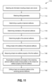
- FIG. 11 is a flowchart illustrating a method 1110 of producing a geothermal well including dynamically replanning at least some planned wellbores of the geothermal well.
- the method 1110 includes obtaining site information including at least a site volume at 1112.
- obtaining the site information includes accessing the site information from a local hardware storage device.
- a hardware storage device is any non-transient computer readable medium that may store instructions thereon.
- the hardware storage device may be any type of solid-state memory; volatile memory, such as static random access memory (SRAM) or dynamic random access memory (DRAM); non-volatile memory, such as read-only memory (ROM) including programmable ROM (PROM), erasable PROM (EPROM) or EEPROM; magnetic storage media, such as magnetic tape; a platen-based storage device, such as hard disk drives; optical media, such as compact discs (CD), digital video discs (DVD), Blu-ray Discs, or other optical media; removable media such as USB drives; non-removable media such as internal SATA or non-volatile memory express (NVMe) style NAND flash memory; or any other non-transient storage media.
- obtaining the site information includes accessing the site information from a remote storage device, such as a cloud storage device or server computer.
- the site information includes at least a site volume that is defined by a property limit and a maximum allowable depth.
- the site volume further includes no-drill zones that will limit the positioning of planned wellbores within the site volume.
- the site information includes a geothermal profile of the site. For example, different properties of the site may affect the geothermal properties, such as groundwater presence, formation composition, and other underground structures such as other pipes and wells.
- the site information further includes an allowed drilling area located at the surface of the site volume.
- the method 1110 further includes obtaining drilling parameters at 1114.
- the drilling parameter may include wellbore properties including a thermal transfer rate, a cost-per-meter for drilling a wellbore in the geological formation, a cost-per-start for each wellbore, a drilling rate, a maximum angle, a minimum wellbore length, a maximum wellbore length, a maximum well length (e.g., total length of the wellbores), minimum distance between wellbores, and other properties of the drilling and costs associated therewith.
- the drilling parameters allow a machine learning model or other model to determine the planned geothermal well when considered in context of the site information.
- the method 1110 includes determining a quantity of planned wellbores having a shared wellhead at 1116 before determining orientations of the planned wellbores at 1118 and determining lengths of the planned wellbores at 1120.
- determining the quantity of planned wellbores includes receiving a predetermined quantity of planned wellbores from an operator. For example, drilling constraints may limit the ability of a drilling team to produce the geothermal well, limiting the quantity of wellbores.
- the quantity of planned wellbores may be selected by an operator based on the cost of BHEs or other materials involved with the construction of the geothermal well and associated HVAC equipment.
- a model iterates through a plurality of instances to determine the quantity of planned wellbores, as described herein.
- Determining the orientations and determining the lengths of the planned wellbores as well as the wellhead coordinates is based at least partially on the site information and the drilling parameters.
- an orientation and length of the planned wellbore may be based at least partially on a maximum allowable depth of the site volume and/or a maximum angle of the wellbore relative to the surface.
- the orientation and length of the planned wellbore may be based at least partially on the geothermal profile of the site volume, such as the temperature increasing proximate a lower region of the site volume or a presence of groundwater in the site volume limiting a length of the wellbore.
- the method 1110 further includes drilling at least a first drilled wellbore according to a first planned wellbore location at 1122. In some embodiments, the method 1110 includes measuring at least one wellbore property of the first drilled wellbore at 1146. In some examples, the wellbore property is measured during drilling of the first drilled wellbore. In some examples, the wellbore property is measured after drilling the first drilled wellbore.
- the wellbore property includes a location of the drilled wellbore, such as a location of the downhole end of the drilled wellbore or a substantially continuous measurement of the location of the drilled wellbore along at least a portion of the length of the drilled wellbore in the site volume; an orientation of the drilled wellbore, such as an average orientation or a substantially continuous measurement of the orientation of the drilled wellbore along at least a portion of the length of the drilled wellbore in the site volume; a length of the drilled wellbore; a depth of the drilled wellbore; formation properties including formation composition, water production, fractures, etc.; thermal transfer rate from the formation; thermal recovery rate from the formation to a BHE for the drilled wellbore; and drilling cost for the drilled wellbore, such as cost-per-foot for drilling the drilled wellbore and start cost for drilling the drilled wellbore.
- a location of the drilled wellbore such as a location of the downhole end of the drilled wellbore or
- the start cost for drilling a drilled wellbore may be greater than expected, rendering less but longer wellbores more economical in the drilling costs for the geothermal well.
- the orientation of the wellbore is measured via an inclinometer and compared to the orientation of the planned wellbore.
- the wellbore property is used in recalculating orientations and lengths of the remaining planned wellbores based at least partially on the at least one wellbore property at 1148.
- the measured wellbore property (or a calculated wellbore property based on a measured wellbore property) is provided as an input to the machine learning model or other model described herein.
- the machine learning model or other model determines orientations and lengths of the remaining planned wellbores of the geothermal well, and optionally wellhead location, relative to the known location, orientation, and/or length of the drilled wellbores.
- the method 1110 further includes drilling at least one remaining wellbore of the remaining planned wellbores that were calculated based at least partially on the at least one wellbore property at 1150. In some embodiments, the method 1110 includes drilling all remaining wellbores of the remaining planned wellbores. In some embodiments, the method 1110 includes drilling one remaining wellbore of the remaining planned wellbores and subsequently measuring at least one wellbore property of the immediately previously drilled wellbore (i.e., the newly drilling wellbore) at 1146. The method 1110, in some embodiments, then cycles by recalculating orientations and lengths of the remaining planned wellbores based at least partially on the at least one wellbore property of the immediately previously drilled wellbore.
- the array of remaining planned wellbores is recalculated after each wellbore is drilled and at least one wellbore property of the immediately previously drilled wellbore is measured.
- the orientations and lengths of remaining planned wellbores are recalculated after only the first drilled wellbore, as many of the relevant wellbore properties (pertaining to other wellbores in the geothermal well) may be measurable from the first drilled wellbore.
- the orientations and lengths of remaining planned wellbores are recalculated at intervals, such as every two wellbores.
- at least one wellbore property is measured during or after each drilling wellbore is drilled, but the orientations and lengths of remaining planned wellbores are only recalculated when a value of the measured wellbore property is outside of an expected range of values.
- the orientations and lengths of remaining planned wellbores are recalculated when the orientation of a drilled wellbore is out of the planned specification by at least 2° or another predetermined threshold, otherwise, the orientations and lengths of remaining planned wellbores are not recalculated.
- the orientations and lengths of remaining planned wellbores are recalculated when the drilling cost (e.g., cost-per-foot and/or start cost) of a drilled wellbore is out of the planned specification by at least 5% or another predetermined threshold, otherwise, the orientations and lengths of remaining planned wellbores are not recalculated.
- the drilling cost e.g., cost-per-foot and/or start cost
- CRM computer-readable media
- a CRM may include instructions that cause a computing device to perform at least some of the method described in relation to FIG. 2 .
- a CRM may include instructions that cause a computing device to perform at least some of the method described in relation to FIG. 11 .
- a CRM may include instructions that cause a computing device to perform at least some of the statistical models, optimization models, machine learning models, or other models described herein.
- a system 1260 for planning and creating a geothermal well includes at least a processor 1262 and a hardware storage device 1264, such as illustrated in FIG. 12 .
- the hardware storage device 1264 is a non-transient storage device including any of RAM, ROM, EEPROM, CD-ROM or other optical disk storage (such as CDs, DVDs, etc.), magnetic disk storage or other magnetic storage devices, or any other medium which can be used to store desired program code in the form of computer-executable instructions or data structures and which can be accessed by a general purpose or special purpose computer.
- the hardware storage device 1264 includes instructions stored thereon that cause the system 1260 to perform one or more portions of any method described herein.
- the system 1260 is configured to display or otherwise present one or more visualizations to a user of an output of the method or models stored on the hardware storage device 1264 to a display 1266.
- the present disclosure relates to systems and methods for planning and/or producing a geothermal well according to any of the following:
- references to "one embodiment” or “an embodiment” of the present disclosure are not intended to be interpreted as excluding the existence of additional embodiments that also incorporate the recited features.
- any element described in relation to an embodiment herein may be combinable with any element of any other embodiment described herein, to the extent such features are not described as being mutually exclusive.
- Numbers, percentages, ratios, or other values stated herein are intended to include that value, and also other values that are "about”, “substantially”, or “approximately” the stated value, as would be appreciated by one of ordinary skill in the art encompassed by embodiments of the present disclosure.
- a stated value should therefore be interpreted broadly enough to encompass values that are at least close enough to the stated value to perform a desired function or achieve a desired result.
- the stated values include at least the variation to be expected in a suitable manufacturing or production process, and may include values that are within 5%, within 1%, within 0.1%, or within 0.01% of a stated value.
- any references to “up” and “down” or “above” or “below” are merely descriptive of the relative position or movement of the related elements.
Landscapes
- Engineering & Computer Science (AREA)
- Life Sciences & Earth Sciences (AREA)
- Mining & Mineral Resources (AREA)
- Geology (AREA)
- Physics & Mathematics (AREA)
- Environmental & Geological Engineering (AREA)
- Fluid Mechanics (AREA)
- General Life Sciences & Earth Sciences (AREA)
- Geochemistry & Mineralogy (AREA)
- Combustion & Propulsion (AREA)
- Mechanical Engineering (AREA)
- General Engineering & Computer Science (AREA)
- Chemical & Material Sciences (AREA)
- Sustainable Energy (AREA)
- Sustainable Development (AREA)
- Geophysics (AREA)
- Management, Administration, Business Operations System, And Electronic Commerce (AREA)
Abstract
Description
- N/A
- Ground source heat pump systems are conventionally conceived with vertical wells that extend in depth from about 50 to 250 meters. During the design phase, the wells are positioned after estimating the total length required to cover all or a portion of a building thermal needs. To estimate the required length, crude approximations are often used, such as with the American Society of Heating, Refrigerating, and Air-Conditioning Engineers (ASHRAE) method: a simple equation provides the total drilled length of vertical wellbores as a function of the building thermal power needs at different time scales with a temperature penalty term linked to the thermal interactions between the wells and their spacings.
- In some embodiments, a method of producing a geothermal well includes obtaining site information including at least a site volume; obtaining drilling parameters; determining a quantity of planned wellbores having a shared wellhead based at least partially on the site information and drilling parameters; determining orientations of the planned wellbores based at least partially on the site information, the drilling parameters, and the quantity of wellbores to position wellbores within boundaries of the site volume; determining lengths of the planned wellbores based at least partially on the site information, the drilling parameters, and the quantity of wellbores to position wellbores within boundaries of the site volume; and drilling at least a first wellbore of the planned wellbores based on a determined orientation and a determined length from the shared wellhead.
- In some embodiments, a method of producing a geothermal well includes obtaining site information including at least a site volume; obtaining drilling parameters; determining a quantity of planned wellbores having a shared wellhead based at least partially on the site information and drilling parameters; determining orientations of the planned wellbores based at least partially on the site information, the drilling parameters, and the quantity of wellbores to position wellbores within boundaries of the site volume; determining lengths of the planned wellbores based at least partially on the site information, the drilling parameters, and the quantity of wellbores to position wellbores within boundaries of the site volume; drilling a first drilled wellbore of the planned wellbores based on a determined orientation and a determined length from the shared wellhead; measuring at least one wellbore property of the first drilled wellbore; recalculating orientations and lengths of remaining planned wellbores based at least partially on the at least one wellbore property of the first drilled wellbore; and drilling at least one drilled remaining wellbore of the remaining planned wellbores.
- In some embodiments, a method of producing a geothermal well includes obtaining site information including at least a site volume; obtaining drilling parameters; determining a quantity of planned wellbores having a shared wellhead based at least partially on the site information and drilling parameters; determining orientations of the planned wellbores based at least partially on the site information, the drilling parameters, and the quantity of wellbores to position wellbores within boundaries of the site volume; determining lengths of the planned wellbores based at least partially on the site information, the drilling parameters, and the quantity of wellbores to position wellbores within boundaries of the site volume; drilling a first drilled wellbore of the planned wellbores based on a determined orientation and a determined length from the shared wellhead; measuring at least one wellbore property of the first drilled wellbore; recalculating orientations and lengths of remaining planned wellbores based at least partially on the at least one wellbore property of the first drilled wellbore; and drilling an additional wellbore based at least partially on a measured wellbore property of a previously drilled wellbore.
- This summary is provided to introduce a selection of concepts that are further described below in the detailed description. This summary is not intended to identify key or essential features of the claimed subject matter, nor is it intended to be used as an aid in limiting the scope of the claimed subject matter.
- Additional features and aspects of embodiments of the disclosure will be set forth in the description which follows, and in part will be obvious from the description, or may be learned by the practice of such embodiments. The features and aspects of such embodiments may be realized and obtained by means of the instruments and combinations particularly pointed out in the appended claims. These and other features will become more fully apparent from the following description and appended claims or may be learned by the practice of such embodiments as set forth hereinafter.
- In order to describe the manner in which the above-recited and other features of the disclosure can be obtained, a more particular description will be rendered by reference to specific embodiments thereof which are illustrated in the appended drawings. For better understanding, the like elements have been designated by like reference numbers throughout the various accompanying figures. While some of the drawings may be schematic or exaggerated representations of concepts, non-schematic drawings should be considered as being to scale for some embodiments of the present disclosure, but not to scale for other embodiments contemplated herein. Understanding that the drawings depict some example embodiments, the embodiments will be described and explained with additional specificity and detail through the use of the accompanying drawings in which:
-
FIG. 1 is a schematic diagram of a geothermal well in a site volume, according to some embodiments of the present disclosure; -
FIG. 2 is a flowchart illustrating a method of producing a geothermal well, according to some embodiments of the present disclosure; -
FIG. 3 is a graph illustrating the change in thermal recovery scores of geothermal wells of different wellbore quantities, according to some embodiments of the present disclosure; -
FIG. 4 is a flowchart illustrating inputs and output of a statistical model, according to some embodiments of the present disclosure; -
FIG. 5-1 and FIG. 5-2 are schematic diagrams of a geothermal well in a site volume, according to some embodiments of the present disclosure; -
FIG. 6-1 is a schematic diagram of a geothermal well in a site volume with a rectangular shared wellhead, according to some embodiments of the present disclosure; -
FIG. 6-2 is a schematic diagram of a geothermal well in a site volume with a plurality of shared wellheads, according to some embodiments of the present disclosure; -
FIG. 7 illustrates the results of a statistical model calculating a thermal recovery score for a geothermal well with 9 wellbores, according to some embodiments of the present disclosure; -
FIG. 8 illustrates the results of a statistical model calculating a thermal recovery score for a geothermal well with 11 wellbores, according to some embodiments of the present disclosure; -
FIG. 9 illustrates the results of a statistical model calculating a thermal recovery score for a geothermal well with 13 wellbores, according to some embodiments of the present disclosure; -
FIG. 10 is a flowchart illustrating additional inputs and output of a statistical model, according to some embodiments of the present disclosure; -
FIG. 11 is a flowchart illustrating a method of producing a geothermal well with recalculated orientation and lengths of wellbores during the drilling process, according to some embodiments of the present disclosure; and -
FIG. 12 is a system diagram illustrating a system for planning a geothermal well, according to some embodiments of the present disclosure. - Embodiments of the present disclosure generally relate to devices, systems, and methods for planning and drilling a geothermal well. More specifically, embodiments of the present disclosure relate to calculating and drilling a geothermal well with an array of wellbores with the most efficient thermal recovery from the formation. Drilling a geothermal well allows the positioning of wellbore heat exchangers (BHEs) in the wellbores of the well. The BHEs transfer heat between a home, office, or other building primarily above ground with the geologic formation underground. Because the geologic formation remains substantially constant in temperature, the BHEs of the geothermal well can heat the building in colder temperatures above ground and cool the building in hotter temperatures above ground. To provide sufficient thermal transfer rates and sufficient thermal capacity through the BHEs to and from the geologic formation, the geothermal well can include a plurality of wellbores and a plurality of BHEs.
- Conventional geothermal wells include a plurality of vertical wellbores positioned throughout a field or area that allows each wellbore of the well to exchange heat with a different portion of the geological formation. However, drilling a plurality of wellbores from a plurality of locations requires moving the drilling equipment and managing a plurality of connections and contacts above ground. For example, an array of wellbores can be located across a 100 meter (m) by 100m field, increasing drilling costs during creation of the geothermal well and maintenance costs over time of the geothermal well.
- In some embodiments according to the present disclosure, a method of drilling a geothermal well includes designing and drilling a plurality of non-vertical wellbores from a shared wellhead. In some embodiments, a center wellbore is substantially vertical, at least two of the remaining wellbores of the plurality of wellbores are non-vertical. A method of drilling a geothermal well, in some embodiment, includes obtaining and inputting site information and drilling parameters into a model or system that determines and outputs an array of planned wellbores that distributes the planned wellbores within an available volume of geological formation based on the thermal transfer rates available in the geological formation.
-
FIG. 1 is a perspective view of a plannedgeothermal well 100 according to some embodiments of the present disclosure. For example, the plannedgeothermal well 100 includes a plurality of plannedwellbores 102 that each have at least an orientation and a length. In some examples, the orientation is relative to the direction of gravity. In some examples, the orientation is relative to a surface orientation, such as when the wellhead is located on a hillside. In the illustrated embodiment, the surface orientation is substantially perpendicular to the direction of gravity, such that the orientation of the wellbore is substantially the same whether considered relative to the surface orientation or the direction of gravity. - In some embodiments, the planned
geothermal well 100 is determined based at least partially on a variety of site constraints. The site constraints are determined from site information. The site information includes, but is not limited to,surface property limits 104, no-drill zones 106, maximumallowable depth 108, geothermal profile of the site, and other information. The surface property limits 104 (e.g., property boundary) and the maximumallowable depth 108 define the outer bounds of a site volume in whichwellbores 102 may be drilled. In some embodiments, the site volume is further defined by no-drill zones 106, such as building foundations, drainage, storage tanks, wastewater tanks, other underground structures, and any applicable buffer areas around such underground structures. In some embodiments, the site constraints further include a sharedwellhead region 140 from which thewellbores 102 of thegeothermal well 100 may originate at the surface. - As illustrated in
FIG. 1 , the site volume provides the volume in which wellbores may be drilled and/or positioned and, based at least partially on a geothermal profile, the thermal capacity available by a given plannedgeothermal well 100. In some embodiments, the geothermal profile may be assumed to be a constant profile relative to the surface. In some embodiments, the geothermal profile may be assumed to be a constant value throughout the site volume for initial calculations and/or drilling. In some embodiments, the geothermal profile for the site volume is known from prior measurements or records. In some embodiments, the geothermal profile is estimated from similar sites. - In some embodiments, while the site volume allows for wellbores to be positioned at any locations therein, the drilling of the wellbores is limited to an allowed drilling area. For example, the allowed drilling area may be limited for legal reasons, such as property easements that allow access to the site, or for logistical reasons, such as access from a road or due to impassable terrains. In some embodiments, an allowed drilling area on the surface defines a region of the surface from which the wellbores may be drilled. In some non-limiting examples, each of the wellbores may originate from a shared wellhead from which all of the wellbores may be drilled without substantially moving the drilling equipment.
- The planned
geothermal well 100 may be further determined based at least partially on drilling constraints and/or drilling parameters, such as wellbore properties including a thermal transfer rate, a cost-per-meter for drilling a wellbore in the geological formation, a cost-per-start for each wellbore, a drilling rate, a maximum angle, a minimum wellbore length, a maximum wellbore length, a maximum well length (e.g., total length of the wellbores), minimum distance between wellbores, and other properties of the drilling and costs associated therewith. For example, the expense of initiating drilling a wellbore may have an overhead cost associated therewith before any wellbore is drilled. In at least one example, drilling an additional 10 meters on 10 wellbores may cost less than drilling an 11th wellbore with a length of 100 meters. However, based upon the site information and/or site constraints, drilling an additional 10 meters may not be possible without exceeding a maximum allowable depth. - In some embodiments, the planned
geothermal well 100 is determined based at least partially on project constraints, which are high-level constraints on the plannedgeothermal well 100, such as the required total thermal capacity and a cost limit. -
FIG. 2 is a flowchart illustrating an embodiment of amethod 210 of drilling a geothermal well. In some embodiments, themethod 210 includes obtaining site information including at least a site volume at 212. In some embodiments, obtaining the site information includes accessing the site information from a local hardware storage device. For example, a hardware storage device is any non-transient computer readable medium that may store instructions thereon. The hardware storage device may be any type of solid-state memory; volatile memory, such as static random access memory (SRAM) or dynamic random access memory (DRAM); non-volatile memory, such as read-only memory (ROM) including programmable ROM (PROM), erasable PROM (EPROM) or EEPROM; magnetic storage media, such as magnetic tape; a platen-based storage device, such as hard disk drives; optical media, such as compact discs (CD), digital video discs (DVD), Blu-ray Discs, or other optical media; removable media such as USB drives; non-removable media such as internal SATA or non-volatile memory express (NVMe) style NAND flash memory; or any other non-transient storage media. In some embodiment, obtaining the site information includes accessing the site information from a remote storage device, such as a cloud storage device or server computer. - The site information includes at least a site volume that is defined by a property limit and a maximum allowable depth. In some embodiments, the site volume further includes no-drill zones that will limit the positioning of planned wellbores within the site volume. In some embodiments, the site information includes a geothermal profile of the site. For example, different properties of the site may affect the geothermal properties, such as groundwater presence, formation composition, and other underground structures such as other pipes and wells. In some embodiments, the site information further includes an allowed drilling area located at the surface of the site volume.
- In some embodiments, the
method 210 further includes obtaining drilling parameters at 214. The drilling parameter may include wellbore properties including a thermal transfer rate, a cost-per-meter for drilling a wellbore in the geological formation, a cost-per-start for each wellbore, a drilling rate, a maximum angle, a minimum wellbore length, a maximum wellbore length, a maximum well length (e.g., total length of the wellbores), minimum distance between wellbores, and other properties of the drilling and costs associated therewith. The drilling parameters allow a machine learning model or other model to determine the planned geothermal well when considered in context of the site information. - The
method 210 may include determining a quantity of planned wellbores at 216 before determining orientations of the planned wellbores at 218 and determining lengths of the planned wellbores at 220. In some embodiments, determining the quantity of planned wellbores includes receiving a predetermined quantity of planned wellbores from an operator. For example, drilling constraints may limit the ability of a drilling team to produce the geothermal well, limiting the quantity of wellbores. In other examples, the quantity of planned wellbores may be selected by an operator based on the cost of BHEs or other materials involved with the construction of the geothermal well and associated HVAC equipment. In such cases, the quantity of planned wellbores may be one of the drilling parameters obtained at 214. In some embodiments, a machine learning model or other model iterates through a plurality of instances and/or nodes to determine the quantity of planned wellbores, as will be described in more detail herein. - Determining the orientations and determining the lengths of the planned wellbores is based at least partially on the site information and the drilling parameters. For example, an orientation and length of the planned wellbore may be based at least partially on a maximum allowable depth of the site volume and/or a maximum angle of the wellbore relative to the surface. In some examples, the orientation and length of the planned wellbore may be based at least partially on the geothermal profile of the site volume, such as the temperature increasing proximate a lower region of the site volume or a presence of groundwater in the site volume limiting a length of the wellbore. Determining the quantity, orientation, and length of the planned wellbores of the geothermal well will be described in more detail herein.
- The
method 210 further includes drilling at least a first wellbore of the planned wellbores at 222. In some embodiments, themethod 210 includes drilling all of the wellbores of the geothermal well. In some embodiments, and as will be described herein, themethod 210 includes drilling the first wellbore and using the first wellbore to obtain additional site information and/or drilling parameters to further refine the planned geothermal well and/or the planned wellbore(s). This operation is an optional configuration. In other configurations, the method may output the determined orientation and length, for instance for visualization by an user or as drilling instructions for drilling systems. - In some embodiments, determining the quantity, orientations, and lengths of the planned wellbores of the planned geothermal well includes using a machine learning model or other model with equality constraints and inequality constraints. In some examples, the equality constraints include a total length of wellbores in the well, such as a constant L*. In some examples, the equality constraints include a pre-determined or fixed quantity of wellheads, such as 1, 2, 3, 4, 5, or more. In most examples, the quantity of wellheads is a few or less, based on the site information and/or the logistics of accessing the allowable drilling areas.
- In some embodiments, the inequality constraints are more flexible and may include a variety of conditions and properties, as long as a starting configuration can be found that satisfies them all. In some examples, the inequality constraints include a maximum angle. For example, the inclination of a wellbore must be smaller than some maximum angle θ ∗. In at least one example, an inequality constraint is that each wellbore must be longer than some minimal length l ∗. In at least one example, an inequality constraint is that all parts of a wellbore or the well must be within the site volume, where the site volume is defined by a maximum depth of D∗ (for example, 200 m) and a polygon in the x, y-plane, defining the property limits (e.g., boundary of the property). In at least one example, an inequality constraint is that two wellbores cannot be too close to each other, which may be determined by the model.
- Other constraints can easily be added while allowing the constraints to be evaluated in a reasonable period of time. In some embodiments, additional constraints limit the search space, as new configurations may be attempted only if the configurations adhere to all the constraints. In some embodiments, the model would be allowed to explore illegal configurations, but penalizing such configurations with a penalty proportional to the amount of the constraints that are broken. This penalty would then increase to a level where it would never be beneficial to the model to attempt illegal configurations which would lead to the same global optimum. However, this would enable to start in an illegal configuration to find a legal configuration.
- In some embodiments, the model is an optimization model. It may, for instance, include a machine learning model. As used herein, a "machine learning model" refers to a computer algorithm or model (e.g., a classification model, a regression model, a language model, an object detection model) that can be tuned (e.g., trained) based on training input to approximate unknown functions. For example, an ML model may refer to a neural network or other machine learning algorithm or architecture that learns and approximates complex functions and generate outputs based on a plurality of inputs provided to the machine learning model. In some embodiments, an ML system, model, or neural network described herein is an artificial neural network. In some embodiments, an ML system, model, or neural network described herein is a convolutional neural network. In some embodiments, an ML system, model, or neural network described herein is a recurrent neural network. In at least one embodiment, an ML system, model, or neural network described herein is a Bayes classifier. As used herein, a "machine learning system" may refer to one or multiple ML models that cooperatively generate one or more outputs based on corresponding inputs. For example, an ML system may refer to any system architecture having multiple discrete ML components that consider different kinds of information or inputs.
- In at least one embodiment, the system is representable by using a matrix:

- This is used together with a matrix of wellhead positions:

i , yki , zki ). If there is only one shared wellhead position where all wellbores start, this latter list is not necessary. In some embodiments, zk is a predefined constant, meaning that also these coordinates are also essentially 2D, from a function optimization perspective. In some examples, zk is chosen so that zk < 0, where positive direction is down into the formation. In such an example, having zk < 0 means that the wellhead is above ground level, which means that the wellbores do not meet up into a singularity at z = 0. - Finally, there is an index i ∗ that defines the index of a wellbore that adjusts its length to ensure that the total length of all wellbores is L* as per the equality constraint provided.
- In this example, assuming that boundaries are given, each wellbore i may be constructed by starting at the wellhead position with index ki, and extend the wellbore in a straight line with inclination θi and azimuth φi until it intersects a boundary of the site volume, such as the maximum allowable depth D ∗ or any side of the polygon that defines the property limits (whatever is closer). The length Li of the wellbore is computed as the distance from where the well enters the ground at z = 0 to where it is stopped by maximum depth or the polygon boundary. In some embodiments including an equality constraint on the maximum length of all wells, the length Li of the wellbore is calculated by defining a well i ∗, for which:

- In other words, Li ∗ will be adjusted so that ΣLi = L ∗. This length might or might not be acceptable for the planned geothermal well or wellbore(s). For example, the result may be negative or exceed the maximum depth. Such is an example that may benefit from a model where such an infraction leads to a penalty, rather than to discard every such configuration, as discussed herein. This allows the system to start in a configuration where wellbore i ∗ is outside of its allowed range, which is generally quickly solved by the model in order for the machine learning model to reduce the penalty of the infraction.
- In some embodiments, a set (X, W, M, i ∗) describes a starting and end position of each wellbore, which means that it can be transformed into the necessary format of any function f(Z) needed. For example, defining Z = (X, W, M, i ∗) allows consideration of the function f(X, W, M, i ∗).
- In some embodiments, the function operates on a list of coordinates V = [v 1 v 2 ...vn ], where vi defines the coordinates of object (e.g., wellbore) i. In some embodiments, V corresponds to X with vi = [θi φi ]┬ (for instance if the wellhead position(s) is/are already set), or W with vi = [xi yi zi ]┬ if the wellbore orientations are already set but the wellhead positions are not). In another embodiment, a machine learning model, other model, or system of models according to the present disclosure operates on multiple lists in parallel, for example X and W. The model(s) may use a different radius for each (for example, due to the difference in coordinate system) within a single list:

- A model f(V) is an optimization model set to optimize one or more parameters of the system. In some embodiments, a model f(V) = s , where s is the thermal recovery score of the configuration V, operates to find a local maximum for s. It should be understood that the thermal recovery score, which represents the efficiency of heat collection by the array of wellbores, is calculated in a negative value, wherein greater values (i.e., less negative values) reflect a more efficient recovery of thermal energy. Such optimization model may for instance include a function derived of a g-function, which represents the thermal resistance between the borehole and the ground. In some embodiments, the model uses a negative g-function as the model intends to maximize the optimization function.
- However, other optimization functions, taking into account additional parameters, such as project constraints, like the cost, etc. might be used as well depending on the objective of the well placement. In a case where the illegal configurations are accepted, the optimization function may account for a penalty proportional to the amount of the constraints that are broken, in order to encourage the model to go to legal configurations.
- In some embodiments, a method further includes defining a radius r that defines the search radius, and a function legal(V), that returns True if the configuration adheres to all constraints, and False otherwise. In the embodiment above where illegal configurations are accepted, the constraints are taken into account in the optimization function and the use of legal(V) may be optional. In at least one example tested, the function provides a planned geothermal well with a plurality of wellbores by initializing the model according to the following example.
- The example includes generating at least one list V so that legal(V) = True. In some examples, generating the list V includes generating V randomly until a legal configuration is found by chance. In some embodiments, the list V is predetermined by a user or operator for an initial V that is known to be legal.
- Then the example includes searching additional lists V so that legal(V) = True by generating variations of the initial list(s).
- For each vi E V, the method includes creating k alternative positions


- The method may sample randomly around vi , ie.:

- In some embodiments, the method includes, for each alternative position


- In instances when a value for V (j) is legal, where f(V (j)) > f(V), the method then replaces V by V (j). In some embodiments, upon exhaustion of all variations to vi without improvement to the value(s) of V, the method includes decreasing r with a factor λ so that r ← λ · r, where 0 < λ < 1. In some embodiments, when r < r ∗ , the method or model stops.
- This is an example, but the method may stop upon completion of other criteria, such as number of iterations without improvement of the optimization function score, fixed number of iterations, etc.
- In at least one example tested, a model according to at least one embodiment described herein was initialized according to the following initialization values. Total length for all wellbores: L* = 1800. Minimum length of a wellbore: l ∗ = 50. Maximum angle of a wellbore: θ∗ = 20°. Maximum allowable depth: D* = 200. Area of property limits: x ∈ [-30, 30], y E [-30, 30]. Wellhead position: [0,0, -1].
- In this example, the model is configured to determine inclination and azimuth of all wellbores starting from a unique wellhead:

- An evaluation of any well according to the present disclosure is performed, according to at least some embodiments, using a function f(X, i ∗) that acts as a heuristic for optimizing how much geothermal energy can be extracted from the ground. Some general features are that the function values depend on include a length of each wellbore, since a longer well has more surface for absorbing energy; a depth of the wellbore, as temperature difference will be greater at greater depth; and a volume of formation between wellbores, so that the wellbores do not each receive thermal energy from an overlapping region. In some embodiments, the model allows a wellbore or wellbores shorter than l*, but the machine learning model or other model adds a penalty proportional to (l ∗ - lmin ) to the optimization model if the shortest well is shorter than l ∗ . Therefore, the model can evaluate and learn from non-compliant wellbore lengths but will be discouraged from accepting or will not accept a final solution if any well is shorter than l ∗.
- In the described example, a pattern search was used to create alternative positions according to:

- Where vi is each well position. The values were selected according to: k = 24 (e.g., 24 positions) and the alternative positions were evenly spaced on a circle of radius r around each well position vi = [θi φi ]┬. If this results in


- In the example described above with the defined settings for different amounts of wellbores, the model provided the
graph 324 illustrated inFIG. 3 , after attempting each setting one time. To analyse the effect of initialization, the model was run 12 times, with the setup of 11 wells. The model produces a mean score of -12.13 with a standard deviation of 0.13, in the range of [-11.96, -12.34]. - In the described example, an array of 11 wellbores was determined to be the lowest (best) value. In some embodiments, an array with too few wells, such as 9, results in all wells needing to be as long as possible in order to meet the prescribed total length of 1800m. This forces the wells to be closer than optimal to each other which makes their regions of heat exchange overlap more. In some embodiments, an array with too many wells, such as 14, results in all wells needing to be as short as possible in order to meet the total length constraint. This again creates unnecessary overlap of the heat exchange regions of the wells while further leaving the bottom region of the site volume unexploited.
-
FIG. 4 is aflowchart 426 illustrating the inputs ofsite information 428,drilling parameters 430, andproject constraints 432 into thestatistical model 434 as described in the above example. Themodel 434 then provides the values including at least azimuth and inclination angle of the plannedwellbores 436 according to the lowest value calculated. In some embodiments, the planned wellbores originate from approximately a single wellhead and fan out from the single wellhead.FIG. 5-1 is a perspective view of anarray 538 of plannedwellbores 502 produced by the machine learning model or other model described in relation toFIG. 2 andFIG. 3 . Theplanned wellbores 502 originate from an approximatesingle wellhead 540 with the origin located at a height (z-value) above the surface to avoid a singularity.FIG. 5-2 illustrates the location of the downhole ends 542 of the planned wellbores at the lower portion of the site volume to distribute the wellbores throughout the site volume. In the embodiment, illustrated inFIG. 5-1 and 5-2 , the downhole ends form an arc segment when the wellbores are unobstructed by building foundations or other non-building zones. In other regions of the array of planned wellbores, the building foundations or other non-building zones obstruct the wellbores and result in a linear arrangement of the downhole ends in the site volume according to the edge(s) of the building foundations or other non-building zones. - In some embodiments, the shared wellhead is not a single wellhead, but rather a region of allowable wellheads for the array of planned wellbores.
FIG. 6-1 illustrates an embodiment of anarray 638 of plannedwellbores 602 with sharedwellhead region 640 that runs the full length of a surface of the site volume. The planned wellbores then extend downward in a series of wellhead locations. Each wellhead location has a fan of plannedwellbores 602 associated therewith. In such an example, the fans of planned wellbores are parallel to one another, where each fan defines a plane parallel to an adjacent plane. In some embodiments, a plurality of wellbores originates from a shared container at the surface. In some embodiments, thearray 638 includes a plurality of containers at the surface located in thewellhead region 640. For example, thewellhead region 640 ofFIG. 6-2 includes a plurality of wellpads 641-1, 641-2, 641-3 where each wellpad 641-1, 641-2, 641-3 in the shared wellhead region includes a subarray 638-1, 638-2, 638-3 of wellbores. In addition to other properties or values of the geothermal well, a model according to the present disclosure, in some embodiments, calculates the position of one or more wellpads 641-1, 641-2, 641-3 and/or shared wellheads in the sharedwellhead region 640 as explained above. -
FIG. 7 through FIG. 9 illustrate arrays of planned wellbores with associated thermal recovery scores for arrays of 9, 11, and 14 wellbores, respectively.FIG. 7 illustrates the output planned wellbores for an array of 9 wellbores. The machine learning model or other model produced a thermal recovery score of -12.4618 after 60 iterations of the model, as shown in thelefthand graph 744. The array of planned wellbores produced by the model required that all wells are as long as possible to achieve the required total length of 1800m selected during initialization of the model. Upon achieving a consistent series of iterations with no improvement to the thermal recovery score (or improvement to the thermal recovery score less than a predetermined threshold value), the machine learning model or other model terminated and presented the results of the planned well shown in thecenter array 738 and the righthand bottom view of the wellbore ends 742 ofFIG. 7 . - In some embodiments, when the quantity of wellbores in the array are too low, all or all but one of the wellbores is a maximum allowable depth to achieve or approach the minimum total length. In some embodiments, when all or all but one of the wellbores is determined to be the maximum allowable depth to achieve or approach the minimum total length, the machine learning model or other model may increment the quantity of wellbores in the array by one and recalculate the array of planned wellbores.
-
FIG. 8 illustrates the results of a model with an input of 11 wellbores for the calculated array of planned wellbores. With two additional planned wellbores in the array, the machine learning model or other model produced a thermal recovery score of -11.9575 after 100 iterations of the model, as shown in thelefthand graph 844. The array of planned wellbores produced by the model allowed a variety of wellbore lengths to achieve the total length of 1800m selected during initialization of the model. Upon achieving a consistent series of iterations with no improvement to the thermal recovery score (or improvement to the thermal recovery score less than a predetermined threshold value), the machine learning model or other model terminated and presented the results of the planned well shown in thecenter array 838 and the righthand bottom view of the wellbore ends 842 ofFIG. 8 . - In some embodiments, the model increments the quantity of planned wellbores in the array and calculates a new thermal recovery score for the incremented quantity. In response to the thermal recovery score increasing such as described in relation to
FIG. 3 , the model may terminate and present the better score. -
FIG. 9 illustrates the result of the model with an input of 13 wellbores for the calculated array of planned wellbores, which results in a more negative (i.e., worse) thermal recovery score than the 11-wellbore solution described in relation toFIG. 8 . With two additional planned wellbores in the array, the machine learning model or other model produced a thermal recovery score of -13.4458 after 140 iterations of the model, as shown in thelefthand graph 944. The array of planned wellbores produced by the model required the wellbore lengths to be truncated (which forces the wellbores closer to one another and reduces thermal recovery efficiency) to achieve the total length of 1800m selected during initialization of the model. For example, the minimum length of a planned wellbore in the 13-wellbore array is 49 meters compared to 114 meters in the 11-wellbore array and 178 meters in the 9-wellbore array. Upon achieving a consistent series of iterations with no improvement to the thermal recovery score (or improvement to the thermal recovery score less than a predetermined threshold value), the machine learning model or other model terminated and presented the results of the planned well shown in thecenter array 938 and the righthand bottom view of the wellbore ends 942 ofFIG. 9 . - In some embodiments, a method of producing a geothermal well and/or the machine learning model or other model implemented in planning the geothermal well increments the quantity of wellbores are reports or displays the array of planned wellbores (including the associated quantity of wellbores) that provides the least negative and/or better thermal recovery score. In some embodiments, the method of producing a geothermal well and/or the machine learning model or other model further determines the better thermal recovery score relative to cost of producing the geothermal well. In at least one embodiment, the cost of producing the geothermal well is amortized over an expected operational lifetime of the geothermal well. In at least one embodiment, the cost of producing the geothermal well is at least partially offset by the expected value of the thermal recovery from the geothermal well based at least partially on the thermal recovery score calculated for the array of planned wellbores of the geothermal well.
- In some embodiments, a well placement model, such as any of the statistical models and/or machine learning models described herein, is included in a statistical system or model that considers additional constraints or requirements. In some examples, the additional constraints or requirements include, but are not limited to, a building thermal demand over a given period of time (e.g., "lifetime") such as 25 years; the surface equipment space requirements; the surface equipment cost(s); the ground thermal properties such as thermal conductivity, thermal capacity, undisturbed temperatures relative to depth, presence of aquifers; and other constraints or requirements.
- The well placement model, in some embodiments, calculates the minimum total length of wellbore in the well to be drilled to meet the additional constraints or requirements. In some embodiments, the well placement model calculates the greatest thermal recovery score based on a maximum allowed total cost of drilling the well and installing borehole heat exchanger. In some embodiments, the well placement model calculates the greatest thermal recovery score based on a maximum allowed total cost of drilling the well and of installing and operating borehole heat exchanger over the lifetime of the geothermal well.
-
FIG. 10 is aflowchart 1052 including astatistical model 1034 and inputs to thestatistical model 1034 such as that described in relation toFIG. 4 . In some embodiments, additional constraints or requirements are input to thestatistical model 1034 in addition to thesite information 1028, thedrilling parameters 1030, and theproject constraints 1032 described herein. The constraints or requirements include, in some embodiments, acost function 1054. For example, thecost function 1054 may be any function that defines the cost to start a wellbore, the cost-per-meter of a wellbore, the cost of operating the well, the cost relative to inclination or orientation of the wellbore(s), the cost relative to depth of the wellbore(s), the cost for surface equipment or construction (e.g., ditches and/or connections), the cost of subsurface equipment (e.g., borehole heat exchanger), costs offset by thermal recovery, or other costs associated with the creation or operation of the wellbore. - The
statistical model 1034 further receives, in some embodiments,system constraints 1056 and/orsystem inputs 1058. For example, thesystem constraints 1056 may include a range of allowable fluid temperature at an inlet of the borehole heat exchanger, such as a range of -3°C to +40°C. The range of allowable fluid temperatures may place further constraints on the location, orientation, depth, or other calculated values of the plannedwellbores 1036. In another example, thesystem constraints 1056 may include a thermal recovery requirement, such as a nominal value or a proportionate value that is relative to a total building thermal demand of buildings or other structures heated (or cooled) by the geothermal well. In at least one example, thesystem constraints 1056 include a thermal recovery requirement of at least 60% of the total building demand be produced by the geothermal well and theplanned wellbores 1036 thereof. In yet another example, a system constraint may include a location of an aquifer to avoid. - In some embodiments, the
system inputs 1058 include ground properties in addition to the site information, total building thermal demand, seasonal thermal demand information, heat pump or heat exchanger properties, etc. Thesystem inputs 1058 may provide additional nominal or relative values used by thecost function 1054 and/orstatistical model 1034 to determine the plannedwellbores 1036. - As described herein, a thermal recovery score of an array of planned wellbores is based at least partially on the spatial relationship of the planned wellbores within the site volume and the thermal recovery rates from the formation in which the wellbores are drilled. While the site information and drilling parameters obtained and input into the model include the best available information, in some embodiments, the actual information of the site volume, formation information, thermal recovery rates, drilling efficiencies, drilling accuracy, etc. may vary from the input values. In at least one example, a first drilled wellbore of a geothermal well may deviate from the location of an associated first planned wellbore location. In at least another example, a thermal transfer rate of a first drilled wellbore of a geothermal well may vary from the expected thermal transfer rate of the associated first planned wellbore location, even if the drilled wellbore is in the planned wellbore location.
- In some embodiments, planning an array of wellbores for thermal recovery includes drilling at least one wellbore and replanning the array of planned wellbores based on properties or parameters of the drilled wellbore measured during or after drilling the drilled wellbore.
FIG. 11 is a flowchart illustrating amethod 1110 of producing a geothermal well including dynamically replanning at least some planned wellbores of the geothermal well. - In some embodiments, the
method 1110 includes obtaining site information including at least a site volume at 1112. In some embodiments, obtaining the site information includes accessing the site information from a local hardware storage device. For example, a hardware storage device is any non-transient computer readable medium that may store instructions thereon. The hardware storage device may be any type of solid-state memory; volatile memory, such as static random access memory (SRAM) or dynamic random access memory (DRAM); non-volatile memory, such as read-only memory (ROM) including programmable ROM (PROM), erasable PROM (EPROM) or EEPROM; magnetic storage media, such as magnetic tape; a platen-based storage device, such as hard disk drives; optical media, such as compact discs (CD), digital video discs (DVD), Blu-ray Discs, or other optical media; removable media such as USB drives; non-removable media such as internal SATA or non-volatile memory express (NVMe) style NAND flash memory; or any other non-transient storage media. In some embodiment, obtaining the site information includes accessing the site information from a remote storage device, such as a cloud storage device or server computer. - The site information includes at least a site volume that is defined by a property limit and a maximum allowable depth. In some embodiments, the site volume further includes no-drill zones that will limit the positioning of planned wellbores within the site volume. In some embodiments, the site information includes a geothermal profile of the site. For example, different properties of the site may affect the geothermal properties, such as groundwater presence, formation composition, and other underground structures such as other pipes and wells. In some embodiments, the site information further includes an allowed drilling area located at the surface of the site volume. In some embodiments, the
method 1110 further includes obtaining drilling parameters at 1114. The drilling parameter may include wellbore properties including a thermal transfer rate, a cost-per-meter for drilling a wellbore in the geological formation, a cost-per-start for each wellbore, a drilling rate, a maximum angle, a minimum wellbore length, a maximum wellbore length, a maximum well length (e.g., total length of the wellbores), minimum distance between wellbores, and other properties of the drilling and costs associated therewith. The drilling parameters allow a machine learning model or other model to determine the planned geothermal well when considered in context of the site information. - The
method 1110 includes determining a quantity of planned wellbores having a shared wellhead at 1116 before determining orientations of the planned wellbores at 1118 and determining lengths of the planned wellbores at 1120. In some embodiments, determining the quantity of planned wellbores includes receiving a predetermined quantity of planned wellbores from an operator. For example, drilling constraints may limit the ability of a drilling team to produce the geothermal well, limiting the quantity of wellbores. In other examples, the quantity of planned wellbores may be selected by an operator based on the cost of BHEs or other materials involved with the construction of the geothermal well and associated HVAC equipment. In some embodiments, a model iterates through a plurality of instances to determine the quantity of planned wellbores, as described herein. - Determining the orientations and determining the lengths of the planned wellbores as well as the wellhead coordinates is based at least partially on the site information and the drilling parameters. For example, an orientation and length of the planned wellbore may be based at least partially on a maximum allowable depth of the site volume and/or a maximum angle of the wellbore relative to the surface. In some examples, the orientation and length of the planned wellbore may be based at least partially on the geothermal profile of the site volume, such as the temperature increasing proximate a lower region of the site volume or a presence of groundwater in the site volume limiting a length of the wellbore.
- The
method 1110 further includes drilling at least a first drilled wellbore according to a first planned wellbore location at 1122. In some embodiments, themethod 1110 includes measuring at least one wellbore property of the first drilled wellbore at 1146. In some examples, the wellbore property is measured during drilling of the first drilled wellbore. In some examples, the wellbore property is measured after drilling the first drilled wellbore. In some embodiments, the wellbore property includes a location of the drilled wellbore, such as a location of the downhole end of the drilled wellbore or a substantially continuous measurement of the location of the drilled wellbore along at least a portion of the length of the drilled wellbore in the site volume; an orientation of the drilled wellbore, such as an average orientation or a substantially continuous measurement of the orientation of the drilled wellbore along at least a portion of the length of the drilled wellbore in the site volume; a length of the drilled wellbore; a depth of the drilled wellbore; formation properties including formation composition, water production, fractures, etc.; thermal transfer rate from the formation; thermal recovery rate from the formation to a BHE for the drilled wellbore; and drilling cost for the drilled wellbore, such as cost-per-foot for drilling the drilled wellbore and start cost for drilling the drilled wellbore. For example, the start cost for drilling a drilled wellbore may be greater than expected, rendering less but longer wellbores more economical in the drilling costs for the geothermal well. In at least one example, the orientation of the wellbore is measured via an inclinometer and compared to the orientation of the planned wellbore. - The wellbore property is used in recalculating orientations and lengths of the remaining planned wellbores based at least partially on the at least one wellbore property at 1148. For example, the measured wellbore property (or a calculated wellbore property based on a measured wellbore property) is provided as an input to the machine learning model or other model described herein. The machine learning model or other model then determines orientations and lengths of the remaining planned wellbores of the geothermal well, and optionally wellhead location, relative to the known location, orientation, and/or length of the drilled wellbores.
- The
method 1110 further includes drilling at least one remaining wellbore of the remaining planned wellbores that were calculated based at least partially on the at least one wellbore property at 1150. In some embodiments, themethod 1110 includes drilling all remaining wellbores of the remaining planned wellbores. In some embodiments, themethod 1110 includes drilling one remaining wellbore of the remaining planned wellbores and subsequently measuring at least one wellbore property of the immediately previously drilled wellbore (i.e., the newly drilling wellbore) at 1146. Themethod 1110, in some embodiments, then cycles by recalculating orientations and lengths of the remaining planned wellbores based at least partially on the at least one wellbore property of the immediately previously drilled wellbore. In such an example, the array of remaining planned wellbores is recalculated after each wellbore is drilled and at least one wellbore property of the immediately previously drilled wellbore is measured. In some embodiments, the orientations and lengths of remaining planned wellbores are recalculated after only the first drilled wellbore, as many of the relevant wellbore properties (pertaining to other wellbores in the geothermal well) may be measurable from the first drilled wellbore. - In some embodiments, the orientations and lengths of remaining planned wellbores are recalculated at intervals, such as every two wellbores. In some embodiments, at least one wellbore property is measured during or after each drilling wellbore is drilled, but the orientations and lengths of remaining planned wellbores are only recalculated when a value of the measured wellbore property is outside of an expected range of values. For example, the orientations and lengths of remaining planned wellbores are recalculated when the orientation of a drilled wellbore is out of the planned specification by at least 2° or another predetermined threshold, otherwise, the orientations and lengths of remaining planned wellbores are not recalculated. In another example, the orientations and lengths of remaining planned wellbores are recalculated when the drilling cost (e.g., cost-per-foot and/or start cost) of a drilled wellbore is out of the planned specification by at least 5% or another predetermined threshold, otherwise, the orientations and lengths of remaining planned wellbores are not recalculated.
- It should be understood that while embodiments of methods for planning and creating a geothermal well are described herein, embodiments of systems and/or computer readable media having instructions for performing the method are contemplated within the scope of this disclosure. In some embodiments, computer-readable media (CRM) (such as a hardware storage device or other non-transitory media) contains instructions stored thereon that, when executed by a computing device or a processor of a computing device, cause a computing device to perform one or more portions of any method described herein. For example, a CRM may include instructions that cause a computing device to perform at least some of the method described in relation to
FIG. 2 . In other examples, a CRM may include instructions that cause a computing device to perform at least some of the method described in relation toFIG. 11 . In some examples, a CRM may include instructions that cause a computing device to perform at least some of the statistical models, optimization models, machine learning models, or other models described herein. - In some embodiments, a
system 1260 for planning and creating a geothermal well includes at least aprocessor 1262 and ahardware storage device 1264, such as illustrated inFIG. 12 . In some embodiments, thehardware storage device 1264 is a non-transient storage device including any of RAM, ROM, EEPROM, CD-ROM or other optical disk storage (such as CDs, DVDs, etc.), magnetic disk storage or other magnetic storage devices, or any other medium which can be used to store desired program code in the form of computer-executable instructions or data structures and which can be accessed by a general purpose or special purpose computer. Thehardware storage device 1264, in some embodiments, includes instructions stored thereon that cause thesystem 1260 to perform one or more portions of any method described herein. In some embodiments, thesystem 1260 is configured to display or otherwise present one or more visualizations to a user of an output of the method or models stored on thehardware storage device 1264 to adisplay 1266. - The present disclosure relates to systems and methods for planning and/or producing a geothermal well according to any of the following:
- [A1] In some embodiments, a method of producing a geothermal well includes obtaining site information including at least a site volume; obtaining drilling parameters; determining a quantity of planned wellbores having a shared wellhead based at least partially on the site information and drilling parameters; determining orientations of the planned wellbores based at least partially on the site information, the drilling parameters, and the quantity of wellbores to position wellbores within boundaries of the site volume; determining lengths of the planned wellbores based at least partially on the site information, the drilling parameters, and the quantity of wellbores to position wellbores within boundaries of the site volume; and drilling at least a first wellbore of the planned wellbores based on a determined orientation and a determined length from the shared wellhead.
- [A2] In some embodiments, the site information of [A1] includes a geothermal profile.
- [A3] In some embodiments, the site volume of [A1] or [A2] includes a no-drill zone.
- [A4] In some embodiments, the no-drill zone of [A3] includes at least one building foundation.
- [A5] In some embodiments, the stie volume of any of [A1] through [A4] includes property limits and a maximum depth.
- [A6] In some embodiments, the drilling parameters of any of [A1] through [A5] include wellbore properties.
- [A7] In some embodiments, the drilling parameters of any of [A1] through [A6] include a cost-per-foot of a planned wellbore.
- [A8] In some embodiments, the drilling parameters of any of [A1] through [A7] include a wellbore start cost of a planned wellbore.
- [A9] In some embodiments, determining orientations and determining lengths of any of [A1] through [A8] includes calculating a thermal recovery score for each planned wellbore based at least partially on a location relationship of the planned wellbores relative to one another.
- [A10] In some embodiments, calculating a thermal recovery score of [A9] for each planned wellbore is based at least partially on a drilling cost of each planned wellbore.
- [A11] In some embodiments, calculating a thermal recovery score of [A9] for each planned wellbore is based at least partially on a thermal transfer rate of a formation in the site volume.
- [A12] In some embodiments, the method of any of [A1] through [A11] includes determining a shared wellhead location based at least partially on the site volume.
- [A13] In some embodiments, each planned wellbore of any of [A1] through [A12] originates from a single wellhead.
- [A14] In some embodiments, calculating a first thermal recovery score for each planned wellbore based at least partially on a location relationship of the planned wellbores relative to one another; changing the quantity of planned wellbores to a second quantity of planned wellbores; determining orientations of a second array of planned wellbores based at least partially on the site information, the drilling parameters, and a second quantity of wellbores; calculating a second thermal recovery score for each planned wellbore of the second array based at least partially on a location relationship of the planned wellbores relative to one another; and comparing of the first thermal recovery score to the second thermal recovery score; wherein drilling at least a first wellbore of the planned wellbores based on a determined orientation and a determined length from the shared wellhead associated with a better thermal recovery score.
- [B1] In some embodiments, a method of producing a geothermal well includes obtaining site information including at least a site volume; obtaining drilling parameters; determining a quantity of planned wellbores having a shared wellhead based at least partially on the site information and drilling parameters; determining orientations of the planned wellbores based at least partially on the site information, the drilling parameters, and the quantity of wellbores to position wellbores within boundaries of the site volume; determining lengths of the planned wellbores based at least partially on the site information, the drilling parameters, and the quantity of wellbores to position wellbores within boundaries of the site volume; drilling a first drilled wellbore of the planned wellbores based on a determined orientation and a determined length from the shared wellhead; measuring at least one wellbore property of the first drilled wellbore; recalculating orientations and lengths of remaining planned wellbores based at least partially on the at least one wellbore property of the first drilled wellbore; and drilling at least one drilled remaining wellbore of the remaining planned wellbores.
- [B2] In some embodiments, the method of [B1] further includes comparing a measured value of the at least one wellbore property to a predetermined threshold value, and wherein the orientations and lengths of remaining planned wellbores are recalculated in response to the at least one wellbore property exceeding a threshold value or being outside of a range of threshold values.
- [B3] In some embodiments, the method of [B1] or [B2] includes measuring at least one wellbore property of the at least one drilled remaining wellbore and recalculating orientations and lengths of remaining planned wellbores based at least partially on the at least one wellbore property of the at least one drilled remaining wellbore.
- [B4] In some embodiments, the site information of any of [B1] through [B3] includes a geothermal profile of a formation of the site volume.
- [B5] In some embodiments, the method of any of [B1] through [B4] further includes comparing a measured value of the at least one wellbore property to a predetermined threshold value and, in response to the measured value being within a threshold value or range of threshold values, drilling a second drilled wellbore of the planned wellbore.
- [C1] In some embodiments, a method of producing a geothermal well includes obtaining site information including at least a site volume; obtaining drilling parameters; determining a quantity of planned wellbores having a shared wellhead based at least partially on the site information and drilling parameters; determining orientations of the planned wellbores based at least partially on the site information, the drilling parameters, and the quantity of wellbores to position wellbores within boundaries of the site volume; determining lengths of the planned wellbores based at least partially on the site information, the drilling parameters, and the quantity of wellbores to position wellbores within boundaries of the site volume; drilling a first drilled wellbore of the planned wellbores based on a determined orientation and a determined length from the shared wellhead; measuring at least one wellbore property of the first drilled wellbore; recalculating orientations and lengths of remaining planned wellbores based at least partially on the at least one wellbore property of the first drilled wellbore; and drilling an additional wellbore based at least partially on a measured wellbore property of a previously drilled wellbore.
- It should be understood that references to "one embodiment" or "an embodiment" of the present disclosure are not intended to be interpreted as excluding the existence of additional embodiments that also incorporate the recited features. For example, any element described in relation to an embodiment herein may be combinable with any element of any other embodiment described herein, to the extent such features are not described as being mutually exclusive. Numbers, percentages, ratios, or other values stated herein are intended to include that value, and also other values that are "about", "substantially", or "approximately" the stated value, as would be appreciated by one of ordinary skill in the art encompassed by embodiments of the present disclosure. A stated value should therefore be interpreted broadly enough to encompass values that are at least close enough to the stated value to perform a desired function or achieve a desired result. The stated values include at least the variation to be expected in a suitable manufacturing or production process, and may include values that are within 5%, within 1%, within 0.1%, or within 0.01% of a stated value.
- The terms "approximately," "about," and "substantially" as used herein represent an amount close to the stated amount that is within standard manufacturing or process tolerances, or which still performs a desired function or achieves a desired result. For example, the terms "approximately," "about," and "substantially" may refer to an amount that is within less than 5% of, within less than 1% of, within less than 0.1% of, and within less than 0.01% of a stated amount. Further, it should be understood that any directions or reference frames in the preceding description are merely relative directions or movements. For example, any references to "up" and "down" or "above" or "below" are merely descriptive of the relative position or movement of the related elements.
- A person having ordinary skill in the art should realize in view of the present disclosure that equivalent constructions do not depart from the spirit and scope of the present disclosure, and that various changes, substitutions, and alterations may be made to embodiments disclosed herein without departing from the spirit and scope of the present disclosure. Equivalent constructions, including functional "means-plus-function" clauses are intended to cover the structures described herein as performing the recited function, including both structural equivalents that operate in the same manner, and equivalent structures that provide the same function. It is the express intention of the applicant not to invoke means-plus-function or other functional claiming for any claim except for those in which the words 'means for' appear together with an associated function. Each addition, deletion, and modification to the embodiments that falls within the meaning and scope of the claims is to be embraced by the claims. The described embodiments are therefore to be considered as illustrative and not restrictive, and the scope of the disclosure is indicated by the appended claims rather than by the foregoing description.
Claims (19)
- A method of producing a geothermal well, the method comprising:obtaining site information including at least a site volume;obtaining drilling parameters;determining orientations and lengths of planned wellbores of the geothermal well based at least partially on the site information, the drilling parameters, and a model based at least partially on thermal efficiency of the planned wellbores.
- The method of claim 1, wherein the site information further includes one or more of a geothermal profile, property limits, a maximum depth, and a no-drill zone.
- The method of any preceding claim, wherein the site volume is calculated based at least partially on the site information.
- The method of any preceding claim, wherein the drilling parameters include one or more of a wellbore property, a cost-per-foot of a planned wellbore, a wellbore start cost of a planned wellbore, and a total drilled length.
- The method of any preceding claim, wherein determining orientations anddetermining lengths includes calculating a value of the model for a plurality of well configurations, wherein each configuration of the plurality is distinct from the others, andwherein each well configuration includes wellbores with predetermined wellbore parameters, including wellhead position, wellbore orientation, and wellbore length.
- The method of claim 5, including selecting an optimum configuration wherein the value of the model corresponding to the optimum configuration is a local extremum of the model.
- The method of claim 5 or 6, comprising iteratively creating new well configurations by varying a parameter of one wellbore based on the configuration that has the best value for the model.
- The method of any of claims 5 to 7, wherein each of the well configuration is contained in the site volume and has a value of at least one drilling parameter that corresponds to a predetermined value.
- The method of any of claims 5 to 8, wherein the model is based at least partially on one or more of the total installation cost, drilling cost, wellbore length.
- The method of claim 9, wherein calculating a value of the model includes calculating a thermal recovery score for each configuration, wherein the thermal recovery score is based at least partially on a thermal transfer rate of a formation in the site volume.
- The method of any preceding claim, further comprising determining a wellhead location for each of the planned wellbore based at least partially on the site information, the drilling parameters, and the model.
- The method of any preceding claim, wherein each planned wellbore originates from a single wellhead.
- The method of any preceding claim, comprising determining a quantity of planned wellbores based at least partially on the site information and drilling parameters.
- The method of claim 13, wherein the geothermal well is a first geothermal well having a first quantity of planned wellbores, further comprising:calculating a first thermal recovery score for the first geothermal well based at least partially on a location relationship of the planned wellbores relative to one another;changing a quantity of planned wellbores to a second quantity of planned wellbores;determining orientations and lengths of planned wellbores of a second geothermal well having the second quantity of planned wellbores based at least partially on the site information, the drilling parameters, and a model based at least partially on thermal efficiency of the planned wellbores; andcalculating a second thermal recovery score for the second geothermal well based at least partially on a location relationship of the planned wellbores relative to one another;comparing the first thermal recovery score to the second thermal recovery score, and selecting one of the first and second geothermal well based on the comparison.
- The method of any of the preceding claim, further comprising drilling at least a first wellbore of the planned wellbores based on a determined orientation and a determined length.
- The method of claim 15, further comprising:drilling a first drilled wellbore of the planned wellbores based on a determined orientation and a determined length;measuring at least one wellbore property of the first drilled wellbore;recalculating orientations and lengths of remaining planned wellbores based at least partially on the at least one wellbore property of the first drilled wellbore; anddrilling at least one drilled remaining wellbore of the remaining planned wellbores.
- The method according to any of the preceding claims, further comprising outputting the determined orientations and lengths of planned wellbores of the geothermal well.
- A system producing a geothermal well, the system comprising one or more processing units configured for performing the method according to any of claims 1-16.
- A non-transitory computer-readable storage medium including computer program instructions that, when executed by one or more processing units, cause the one or more processing units to perform the method according to any of claims 1-16.
Priority Applications (3)
| Application Number | Priority Date | Filing Date | Title |
|---|---|---|---|
| EP23305387.5A EP4435228B1 (en) | 2023-03-22 | 2023-03-22 | Methods for producing a geothermal well |
| PCT/US2024/021077 WO2024197227A1 (en) | 2023-03-22 | 2024-03-22 | Methods for producing a geothermal well |
| US18/613,365 US12378869B2 (en) | 2023-03-22 | 2024-03-22 | Methods for producing a geothermal well |
Applications Claiming Priority (1)
| Application Number | Priority Date | Filing Date | Title |
|---|---|---|---|
| EP23305387.5A EP4435228B1 (en) | 2023-03-22 | 2023-03-22 | Methods for producing a geothermal well |
Publications (2)
| Publication Number | Publication Date |
|---|---|
| EP4435228A1 true EP4435228A1 (en) | 2024-09-25 |
| EP4435228B1 EP4435228B1 (en) | 2026-02-18 |
Family
ID=85792115
Family Applications (1)
| Application Number | Title | Priority Date | Filing Date |
|---|---|---|---|
| EP23305387.5A Active EP4435228B1 (en) | 2023-03-22 | 2023-03-22 | Methods for producing a geothermal well |
Country Status (3)
| Country | Link |
|---|---|
| US (1) | US12378869B2 (en) |
| EP (1) | EP4435228B1 (en) |
| WO (1) | WO2024197227A1 (en) |
Families Citing this family (4)
| Publication number | Priority date | Publication date | Assignee | Title |
|---|---|---|---|---|
| US12546189B2 (en) | 2024-05-16 | 2026-02-10 | Schlumberger Technology Corporation | Ground-source thermal system for rejecting data center waste heat to a facility |
| US12477687B1 (en) | 2024-05-16 | 2025-11-18 | Schlumberger Technology Corporation | Ground-source thermal system for rejecting data center waste heat to a facility |
| CN119227898B (en) * | 2024-10-12 | 2025-07-11 | 东营明汇新能源科技有限公司 | Geothermal mining and irrigation well group arrangement method based on data analysis |
| CN120776989B (en) * | 2025-07-04 | 2026-01-23 | 中石化绿源地热能(陕西)开发有限公司 | Well drilling and completion method and well drilling optimization system for geothermal well at medium and low temperatures |
Citations (3)
| Publication number | Priority date | Publication date | Assignee | Title |
|---|---|---|---|---|
| EP2811109A1 (en) * | 2013-06-04 | 2014-12-10 | Kongsberg Devotek AS | Method of establishing a well |
| WO2016108913A1 (en) * | 2014-12-31 | 2016-07-07 | Halliburton Energy Services Inc. | Improving geosteering inversion using look-ahead look-around electromagnetic tool |
| WO2023034878A1 (en) * | 2021-08-31 | 2023-03-09 | Helmerich & Payne Technologies, Llc | Systems and methods for drilling geothermal wells |
Family Cites Families (29)
| Publication number | Priority date | Publication date | Assignee | Title |
|---|---|---|---|---|
| CN101595273B (en) | 2006-10-13 | 2013-01-02 | 埃克森美孚上游研究公司 | Optimized well spacing for in situ shale oil development |
| GB2450755B (en) * | 2007-07-06 | 2012-02-29 | Greenfield Energy Ltd | Geothermal energy system and method of operation |
| GB2450754B8 (en) * | 2007-07-06 | 2013-02-06 | Greenfield Energy Ltd | Geothermal energy system and method of operation |
| GB2461029B (en) * | 2008-06-16 | 2011-10-26 | Greenfield Energy Ltd | Thermal energy system and method of operation |
| WO2011163532A2 (en) | 2010-06-23 | 2011-12-29 | Earl Keisling | Space-saving high-density modular data center and an energy-efficient cooling system |
| EP2698498A1 (en) * | 2012-08-17 | 2014-02-19 | Sandvik Mining and Construction Oy | Method, rock drilling rig and control apparatus |
| US12284782B2 (en) | 2012-09-07 | 2025-04-22 | David Lane Smith | Cooling electronic devices installed in a subsurface environment |
| US9351430B2 (en) | 2013-06-13 | 2016-05-24 | Microsoft Technology Licensing, Llc | Renewable energy based datacenter cooling |
| US10927604B2 (en) * | 2016-04-01 | 2021-02-23 | Board of Regents of the University of the Nevada System of Higher Education, on behalf of the University Nevada, Reno | Systems and methods for enhancing energy extraction from geothermal wells |
| CA2963725A1 (en) | 2016-04-07 | 2017-10-07 | James R. Hardin | Data center geothermal cooling |
| US11220882B2 (en) * | 2016-12-23 | 2022-01-11 | Element Coil Services Inc. | Enhancing thermal conductivity of a wellbore |
| US11656002B2 (en) * | 2016-12-23 | 2023-05-23 | Element Coil Services Inc. | Enhancing geothermal energy production in a well |
| US11574372B2 (en) | 2017-02-08 | 2023-02-07 | Upstream Data Inc. | Blockchain mine at oil or gas facility |
| US11224145B2 (en) | 2018-08-01 | 2022-01-11 | Nautilus True, Llc | Datacenter geothermal cooling system and method |
| CA3050274C (en) * | 2018-08-12 | 2022-07-05 | Eavor Technologies Inc. | Method for thermal profile control and energy recovery in geothermal wells |
| DE102019127752B4 (en) | 2019-10-15 | 2025-05-08 | Waiys Gmbh | Data center and procedures |
| US11790320B2 (en) * | 2020-06-25 | 2023-10-17 | Schlumberger Technology Corporation | Approaches to creating and evaluating multiple candidate well plans |
| CN112627797B (en) * | 2020-12-22 | 2022-12-23 | 天津大学 | A special-shaped plume geothermal well development system |
| CN113294137A (en) | 2021-01-08 | 2021-08-24 | 西安交通大学 | Method for establishing hydrothermal geothermal well factory and hydrothermal geothermal well factory |
| EP4320394B1 (en) * | 2021-04-06 | 2024-12-18 | CGG Services SAS | Geothermal plant for extracting energy from a geothermal reservoir located below the ocean bottom |
| US12048115B2 (en) | 2021-11-29 | 2024-07-23 | DataKoolGreen, Inc. | Cooling system |
| CN114585240B (en) | 2022-04-02 | 2023-09-22 | 北京有竹居网络技术有限公司 | Data center waste heat utilization system |
| US12331618B2 (en) * | 2022-05-06 | 2025-06-17 | Low Carbon Energies Llc | System and method for carbon dioxide storage and geothermal heat mining in depleted gas, gas condensate or oil reservoirs |
| CN115493176A (en) | 2022-10-13 | 2022-12-20 | 同济大学 | A heating and cooling system |
| US20230124192A1 (en) | 2022-12-21 | 2023-04-20 | Kevin LIEDTKE | Heating and cooling systems for edge data centers |
| CN116576494A (en) | 2023-04-25 | 2023-08-11 | 中国矿业大学 | An energy management system for cave data centers that combines cooling and cooling, domestic hot water production and heat pump heating |
| CN116518585A (en) | 2023-05-10 | 2023-08-01 | 广东电网有限责任公司广州供电局 | Data center spiral buried pipe waste heat utilization system and control method thereof |
| US20250066927A1 (en) | 2023-08-24 | 2025-02-27 | EnhancedGEO Holdings, LLC | Electrolysis system with a geothermally heated feed stream |
| EP4514079A1 (en) | 2023-08-24 | 2025-02-26 | Ovh | Datacenter liquid cooling arrangement for reducing icing risks of dry coolers |
-
2023
- 2023-03-22 EP EP23305387.5A patent/EP4435228B1/en active Active
-
2024
- 2024-03-22 US US18/613,365 patent/US12378869B2/en active Active
- 2024-03-22 WO PCT/US2024/021077 patent/WO2024197227A1/en not_active Ceased
Patent Citations (3)
| Publication number | Priority date | Publication date | Assignee | Title |
|---|---|---|---|---|
| EP2811109A1 (en) * | 2013-06-04 | 2014-12-10 | Kongsberg Devotek AS | Method of establishing a well |
| WO2016108913A1 (en) * | 2014-12-31 | 2016-07-07 | Halliburton Energy Services Inc. | Improving geosteering inversion using look-ahead look-around electromagnetic tool |
| WO2023034878A1 (en) * | 2021-08-31 | 2023-03-09 | Helmerich & Payne Technologies, Llc | Systems and methods for drilling geothermal wells |
Also Published As
| Publication number | Publication date |
|---|---|
| EP4435228B1 (en) | 2026-02-18 |
| US12378869B2 (en) | 2025-08-05 |
| US20240318537A1 (en) | 2024-09-26 |
| WO2024197227A1 (en) | 2024-09-26 |
Similar Documents
| Publication | Publication Date | Title |
|---|---|---|
| EP4435228B1 (en) | Methods for producing a geothermal well | |
| US12106028B2 (en) | Optimization based on predicted tool performance | |
| US9091141B2 (en) | Systems and methods for dynamically developing wellbore plans with a reservoir simulator | |
| RU2643057C2 (en) | Managing wellbore exploitation with use of uncertainty calculations | |
| EP2597253B1 (en) | Dynamic prediction of downhole temperature distributions | |
| US20190361146A1 (en) | System and method for predicting well production | |
| US12410948B2 (en) | Method for modelling a geothermal installation for the thermal regulation of at least one building | |
| Zalluhoglu et al. | Steering advisory system for mud motors | |
| Witte | A novel tool for assessing negative temperature interactions between neighbouring borehole heat exchanger systems | |
| Yan et al. | An uncertainty-driven peak-integration (UP) strategy for 3D borehole layout planning | |
| US20250103777A1 (en) | Methods and systems for intelligent field development and optimized placement of well pads in unconventional and conventional reservoirs | |
| US20240328296A1 (en) | System and method for efficient optimization of hydrocarbon-production well configuration and trajectory using performance versus drilling-cost profiles | |
| WO2025064894A1 (en) | Methods and systems for intelligent field development and optimized placement of well pads in unconventional and conventional reservoirs | |
| Saradva et al. | Exploring the Potential of Machine Learning Technology to Generate Productivity Maps Using Offset Field Data for a Strategic Coiled Tubing Drilling Program-Onshore Sharjah, UAE | |
| Adiga | Optimizing geothermal well planning under reservoir uncertainty with stochastic programming | |
| Lolon et al. | Augmenting Hybrid Physics-Based Multivariate Analysis with the Alternating Conditional Expectations Approach to Optimize Permian Basin Well Performance | |
| Galas et al. | The Method of Directional Radial Drilling of Channels for Stimulation of Oil Rims | |
| Kharghoria et al. | Productivity-based method for selection of reservoir drilling target and steering strategy | |
| US20240296267A1 (en) | Methods for planning a wellbore | |
| Peng et al. | Water control solutions combining intelligent algorithm and reservoir simulation methods for horizontal wells in bottom water reservoirs | |
| Makhambetov et al. | Geosteering a Well Along the Reservoir Top with Non-Azimuthal Resistivity Measurements, Case Study from Kazakhstan | |
| Kolbikov et al. | Integrated approach for the horizontal well design and geosteering in thin Jurassic sands | |
| Palermo et al. | The combined application of azimuthal deep resistivity and multi-lateral technologies maximizes extra-heavy oil recovery and improves production rates in Junin Block of the Orinoco Oil Belt | |
| Wang et al. | Intelligent Horizontal Well Placement Optimization: Modeling and Application–A Case Study of Low Permeability Carbonate Reservoir in the Middle East | |
| Chen et al. | Surrogate and Dimensionality Reduction-Based Coupled Optimization of Well Pattern and Fracture Network in Tight Oil Reservoirs |
Legal Events
| Date | Code | Title | Description |
|---|---|---|---|
| PUAI | Public reference made under article 153(3) epc to a published international application that has entered the european phase |
Free format text: ORIGINAL CODE: 0009012 |
|
| STAA | Information on the status of an ep patent application or granted ep patent |
Free format text: STATUS: THE APPLICATION HAS BEEN PUBLISHED |
|
| AK | Designated contracting states |
Kind code of ref document: A1 Designated state(s): AL AT BE BG CH CY CZ DE DK EE ES FI FR GB GR HR HU IE IS IT LI LT LU LV MC ME MK MT NL NO PL PT RO RS SE SI SK SM TR |
|
| STAA | Information on the status of an ep patent application or granted ep patent |
Free format text: STATUS: REQUEST FOR EXAMINATION WAS MADE |
|
| 17P | Request for examination filed |
Effective date: 20250321 |
|
| GRAP | Despatch of communication of intention to grant a patent |
Free format text: ORIGINAL CODE: EPIDOSNIGR1 |
|
| STAA | Information on the status of an ep patent application or granted ep patent |
Free format text: STATUS: GRANT OF PATENT IS INTENDED |
|
| RIC1 | Information provided on ipc code assigned before grant |
Ipc: E21B 47/02 20060101AFI20250813BHEP Ipc: E21B 7/04 20060101ALI20250813BHEP Ipc: E21B 33/047 20060101ALI20250813BHEP Ipc: E21B 41/00 20060101ALI20250813BHEP |
|
| INTG | Intention to grant announced |
Effective date: 20250912 |
|
| GRAS | Grant fee paid |
Free format text: ORIGINAL CODE: EPIDOSNIGR3 |
|
| GRAA | (expected) grant |
Free format text: ORIGINAL CODE: 0009210 |
|
| STAA | Information on the status of an ep patent application or granted ep patent |
Free format text: STATUS: THE PATENT HAS BEEN GRANTED |
|
| AK | Designated contracting states |
Kind code of ref document: B1 Designated state(s): AL AT BE BG CH CY CZ DE DK EE ES FI FR GB GR HR HU IE IS IT LI LT LU LV MC ME MK MT NL NO PL PT RO RS SE SI SK SM TR |
|
| REG | Reference to a national code |
Ref country code: CH Ref legal event code: F10 Free format text: ST27 STATUS EVENT CODE: U-0-0-F10-F00 (AS PROVIDED BY THE NATIONAL OFFICE) Effective date: 20260218 Ref country code: GB Ref legal event code: FG4D |
|
| REG | Reference to a national code |
Ref country code: IE Ref legal event code: FG4D |
|
| REG | Reference to a national code |
Ref country code: DE Ref legal event code: R096 Ref document number: 602023012194 Country of ref document: DE |
|
| PGFP | Annual fee paid to national office [announced via postgrant information from national office to epo] |
Ref country code: AT Payment date: 20260301 Year of fee payment: 4 |
|
| REG | Reference to a national code |
Ref country code: CH Ref legal event code: R17 Free format text: ST27 STATUS EVENT CODE: U-0-0-R10-R17 (AS PROVIDED BY THE NATIONAL OFFICE) Effective date: 20260527 |
|
| REG | Reference to a national code |
Ref country code: CH Ref legal event code: U11 Free format text: ST27 STATUS EVENT CODE: U-0-0-U10-U11 (AS PROVIDED BY THE NATIONAL OFFICE) Effective date: 20260529 |
|
| PGFP | Annual fee paid to national office [announced via postgrant information from national office to epo] |
Ref country code: LU Payment date: 20260528 Year of fee payment: 4 |
|
| REG | Reference to a national code |
Ref country code: NL Ref legal event code: MP Effective date: 20260218 |
|
| PG25 | Lapsed in a contracting state [announced via postgrant information from national office to epo] |
Ref country code: RS Free format text: LAPSE BECAUSE OF FAILURE TO SUBMIT A TRANSLATION OF THE DESCRIPTION OR TO PAY THE FEE WITHIN THE PRESCRIBED TIME-LIMIT Effective date: 20260518 |
|
| PG25 | Lapsed in a contracting state [announced via postgrant information from national office to epo] |
Ref country code: ES Free format text: LAPSE BECAUSE OF FAILURE TO SUBMIT A TRANSLATION OF THE DESCRIPTION OR TO PAY THE FEE WITHIN THE PRESCRIBED TIME-LIMIT Effective date: 20260218 |
|
| PG25 | Lapsed in a contracting state [announced via postgrant information from national office to epo] |
Ref country code: PL Free format text: LAPSE BECAUSE OF FAILURE TO SUBMIT A TRANSLATION OF THE DESCRIPTION OR TO PAY THE FEE WITHIN THE PRESCRIBED TIME-LIMIT Effective date: 20260218 |
|
| PG25 | Lapsed in a contracting state [announced via postgrant information from national office to epo] |
Ref country code: GR Free format text: LAPSE BECAUSE OF FAILURE TO SUBMIT A TRANSLATION OF THE DESCRIPTION OR TO PAY THE FEE WITHIN THE PRESCRIBED TIME-LIMIT Effective date: 20260519 |
|
| REG | Reference to a national code |
Ref country code: LT Ref legal event code: MG9D |
|
| PG25 | Lapsed in a contracting state [announced via postgrant information from national office to epo] |
Ref country code: LT Free format text: LAPSE BECAUSE OF FAILURE TO SUBMIT A TRANSLATION OF THE DESCRIPTION OR TO PAY THE FEE WITHIN THE PRESCRIBED TIME-LIMIT Effective date: 20260218 |
|
| PGFP | Annual fee paid to national office [announced via postgrant information from national office to epo] |
Ref country code: DE Payment date: 20260518 Year of fee payment: 4 |
|
| PG25 | Lapsed in a contracting state [announced via postgrant information from national office to epo] |
Ref country code: NO Free format text: LAPSE BECAUSE OF FAILURE TO SUBMIT A TRANSLATION OF THE DESCRIPTION OR TO PAY THE FEE WITHIN THE PRESCRIBED TIME-LIMIT Effective date: 20260518 |
|
| PG25 | Lapsed in a contracting state [announced via postgrant information from national office to epo] |
Ref country code: SE Free format text: LAPSE BECAUSE OF FAILURE TO SUBMIT A TRANSLATION OF THE DESCRIPTION OR TO PAY THE FEE WITHIN THE PRESCRIBED TIME-LIMIT Effective date: 20260218 Ref country code: FI Free format text: LAPSE BECAUSE OF FAILURE TO SUBMIT A TRANSLATION OF THE DESCRIPTION OR TO PAY THE FEE WITHIN THE PRESCRIBED TIME-LIMIT Effective date: 20260218 Ref country code: AT Free format text: LAPSE BECAUSE OF FAILURE TO SUBMIT A TRANSLATION OF THE DESCRIPTION OR TO PAY THE FEE WITHIN THE PRESCRIBED TIME-LIMIT Effective date: 20260218 |
|
| REG | Reference to a national code |
Ref country code: AT Ref legal event code: MK05 Ref document number: 1888223 Country of ref document: AT Kind code of ref document: T Effective date: 20260218 |
|
| PGFP | Annual fee paid to national office [announced via postgrant information from national office to epo] |
Ref country code: CH Payment date: 20260529 Year of fee payment: 4 Ref country code: IE Payment date: 20260529 Year of fee payment: 4 Ref country code: BE Payment date: 20260528 Year of fee payment: 4 |
|
| PG25 | Lapsed in a contracting state [announced via postgrant information from national office to epo] |
Ref country code: HR Free format text: LAPSE BECAUSE OF FAILURE TO SUBMIT A TRANSLATION OF THE DESCRIPTION OR TO PAY THE FEE WITHIN THE PRESCRIBED TIME-LIMIT Effective date: 20260218 |
|
| PG25 | Lapsed in a contracting state [announced via postgrant information from national office to epo] |
Ref country code: PT Free format text: LAPSE BECAUSE OF FAILURE TO SUBMIT A TRANSLATION OF THE DESCRIPTION OR TO PAY THE FEE WITHIN THE PRESCRIBED TIME-LIMIT Effective date: 20260618 Ref country code: IS Free format text: LAPSE BECAUSE OF FAILURE TO SUBMIT A TRANSLATION OF THE DESCRIPTION OR TO PAY THE FEE WITHIN THE PRESCRIBED TIME-LIMIT Effective date: 20260618 |
|
| PG25 | Lapsed in a contracting state [announced via postgrant information from national office to epo] |
Ref country code: NL Free format text: LAPSE BECAUSE OF FAILURE TO SUBMIT A TRANSLATION OF THE DESCRIPTION OR TO PAY THE FEE WITHIN THE PRESCRIBED TIME-LIMIT Effective date: 20260218 |
|
| PGFP | Annual fee paid to national office [announced via postgrant information from national office to epo] |
Ref country code: FR Payment date: 20260529 Year of fee payment: 4 |
|
| PG25 | Lapsed in a contracting state [announced via postgrant information from national office to epo] |
Ref country code: LV Free format text: LAPSE BECAUSE OF FAILURE TO SUBMIT A TRANSLATION OF THE DESCRIPTION OR TO PAY THE FEE WITHIN THE PRESCRIBED TIME-LIMIT Effective date: 20260218 |
|
| PG25 | Lapsed in a contracting state [announced via postgrant information from national office to epo] |
Ref country code: BG Free format text: LAPSE BECAUSE OF FAILURE TO SUBMIT A TRANSLATION OF THE DESCRIPTION OR TO PAY THE FEE WITHIN THE PRESCRIBED TIME-LIMIT Effective date: 20260218 |