EP4435227A2 - On demand flow pulsing system - Google Patents
On demand flow pulsing system Download PDFInfo
- Publication number
- EP4435227A2 EP4435227A2 EP24192982.7A EP24192982A EP4435227A2 EP 4435227 A2 EP4435227 A2 EP 4435227A2 EP 24192982 A EP24192982 A EP 24192982A EP 4435227 A2 EP4435227 A2 EP 4435227A2
- Authority
- EP
- European Patent Office
- Prior art keywords
- rotor
- flow
- bore
- valve
- pulsing system
- Prior art date
- Legal status (The legal status is an assumption and is not a legal conclusion. Google has not performed a legal analysis and makes no representation as to the accuracy of the status listed.)
- Granted
Links
Images



Classifications
-
- E—FIXED CONSTRUCTIONS
- E21—EARTH OR ROCK DRILLING; MINING
- E21B—EARTH OR ROCK DRILLING; OBTAINING OIL, GAS, WATER, SOLUBLE OR MELTABLE MATERIALS OR A SLURRY OF MINERALS FROM WELLS
- E21B7/00—Special methods or apparatus for drilling
- E21B7/24—Drilling using vibrating or oscillating means, e.g. out-of-balance masses
-
- E—FIXED CONSTRUCTIONS
- E21—EARTH OR ROCK DRILLING; MINING
- E21B—EARTH OR ROCK DRILLING; OBTAINING OIL, GAS, WATER, SOLUBLE OR MELTABLE MATERIALS OR A SLURRY OF MINERALS FROM WELLS
- E21B21/00—Methods or apparatus for flushing boreholes, e.g. by use of exhaust air from motor
- E21B21/10—Valve arrangements in drilling-fluid circulation systems
- E21B21/103—Down-hole by-pass valve arrangements, i.e. between the inside of the drill string and the annulus
-
- E—FIXED CONSTRUCTIONS
- E21—EARTH OR ROCK DRILLING; MINING
- E21B—EARTH OR ROCK DRILLING; OBTAINING OIL, GAS, WATER, SOLUBLE OR MELTABLE MATERIALS OR A SLURRY OF MINERALS FROM WELLS
- E21B31/00—Fishing for or freeing objects in boreholes or wells
- E21B31/035—Fishing for or freeing objects in boreholes or wells controlling differential pipe sticking
-
- E—FIXED CONSTRUCTIONS
- E21—EARTH OR ROCK DRILLING; MINING
- E21B—EARTH OR ROCK DRILLING; OBTAINING OIL, GAS, WATER, SOLUBLE OR MELTABLE MATERIALS OR A SLURRY OF MINERALS FROM WELLS
- E21B34/00—Valve arrangements for boreholes or wells
- E21B34/06—Valve arrangements for boreholes or wells in wells
- E21B34/14—Valve arrangements for boreholes or wells in wells operated by movement of tools, e.g. sleeve valves operated by pistons or wire line tools
- E21B34/142—Valve arrangements for boreholes or wells in wells operated by movement of tools, e.g. sleeve valves operated by pistons or wire line tools unsupported or free-falling elements, e.g. balls, plugs, darts or pistons
-
- E—FIXED CONSTRUCTIONS
- E21—EARTH OR ROCK DRILLING; MINING
- E21B—EARTH OR ROCK DRILLING; OBTAINING OIL, GAS, WATER, SOLUBLE OR MELTABLE MATERIALS OR A SLURRY OF MINERALS FROM WELLS
- E21B4/00—Drives for drilling, used in the borehole
- E21B4/02—Fluid rotary type drives
-
- E—FIXED CONSTRUCTIONS
- E21—EARTH OR ROCK DRILLING; MINING
- E21B—EARTH OR ROCK DRILLING; OBTAINING OIL, GAS, WATER, SOLUBLE OR MELTABLE MATERIALS OR A SLURRY OF MINERALS FROM WELLS
- E21B47/00—Survey of boreholes or wells
- E21B47/12—Means for transmitting measuring-signals or control signals from the well to the surface, or from the surface to the well, e.g. for logging while drilling
- E21B47/14—Means for transmitting measuring-signals or control signals from the well to the surface, or from the surface to the well, e.g. for logging while drilling using acoustic waves
- E21B47/18—Means for transmitting measuring-signals or control signals from the well to the surface, or from the surface to the well, e.g. for logging while drilling using acoustic waves through the well fluid, e.g. mud pressure pulse telemetry
Definitions
- the disclosure relates generally to downhole apparatus. More particularly, the disclosure relates to drilling apparatus and drilling methods which include an agitator or flow pulsing apparatus in a drill string.
- a flow pulsing apparatus may be used to oscillate a drill string to reduce friction with a borehole, to enhance tool face control, to extend borehole lengths, and to improve drilling efficiency.
- the flow pulsing apparatus may be used in other downhole work strings as well.
- the flow pulsing system includes a housing having a central axis, a first end, a second end opposite the first end, and a bore extending along the central axis from the first end to the second end. Additionally, some embodiments may include a stator disposed within the bore of the housing having a plurality of lobe cavities and a rotor disposed within the stator. The rotor includes an axis offset from the central axis, a plurality of lobes that mate with the plurality of lobe cavities, and a thru bore extending along the axis.
- some embodiments may include a dart configured to releasably couple with the thru bore of the rotor, the dart including a first radially outer guide section, a second radially outer guide section, a tip, an inner bore, and a releasable nozzle configured to control a first fluid flow through the inner bore and the thru bore.
- a flow pulsing system including a housing having a central axis, a first end, a second end opposite the first end, and a bore extending along the central axis from the first end to the second end. Additionally, some embodiments may include a stator disposed within the bore of the housing having a plurality of lobe cavities and a rotor disposed within the stator. The rotor includes an axis offset from the central axis, a plurality of lobes that correspond with the plurality of lobe cavities, a thru bore extending along the axis.
- some embodiments may include a screen disposed within the bore of the housing, the screen including a body and a coupling surface at a first end of the body, the coupling surface configured to couple to the housing. Additionally, some embodiments may include a screen housing extending to a second end of the body and an inner bore to fluidly communicate with the thru bore.
- Still other embodiments disclosed herein are directed to a flow pulsing system including a housing having a central axis, a first end, a second end opposite the first end, and a bore extending along the central axis from the first end to the second end. Additionally, some embodiments may include a stator disposed within the bore of the housing having a plurality of lobe cavities and a rotor disposed within the stator. The rotor includes an axis offset from the central axis, a plurality of lobes that mate with the plurality of lobe cavities, and a thru bore extending along the axis.
- some embodiments may include a valve section including a stationary valve coupled to the second end of the housing, the stationary valve including a first face, a stationary central port, and a plurality of stationary valve ports. Additionally, some embodiments may include an oscillating valve coupled to the rotor, the oscillating valve including a second face abutting the first face, an oscillating central port in fluid communication with the thru bore of the rotor, and a plurality of oscillating valve ports in fluid communication with the plurality of lobe cavities.
- Embodiments described herein comprise a combination of features and characteristics intended to address various shortcomings associated with certain prior devices, systems, and methods.
- the foregoing has outlined rather broadly the features and technical characteristics of the disclosed embodiments in order that the detailed description that follows may be better understood.
- the various characteristics and features described above, as well as others, will be readily apparent to those skilled in the art upon reading the following detailed description, and by referring to the accompanying drawings. It should be appreciated that the conception and the specific embodiments disclosed may be readily utilized as a basis for modifying or designing other structures for carrying out the same purposes as the disclosed embodiments. It should also be realized that such equivalent constructions do not depart from the spirit and scope of the principles disclosed herein.
- Coupled or “couples” is intended to mean either an indirect or direct connection. Thus, if a first device couples to a second device, that connection may be through a direct connection of the two devices, or through an indirect connection that is established via other devices, components, nodes, and connections.
- axial and axially generally mean along or parallel to a given axis (e.g., central axis of a body or a port), while the terms “radial” and “radially” generally mean perpendicular to the given axis.
- a given axis e.g., central axis of a body or a port
- radial and radially generally mean perpendicular to the given axis.
- an axial distance refers to a distance measured along or parallel to the axis
- a radial distance means a distance measured perpendicular to the axis.
- a flow pulsing system may be used along a drill string to introduce a pressure pulse or pressure wave within a tubular of the drill string.
- a flow pulsing system may be used alone or with other components to provide drilling benefits including enhanced tool face control, improved drilling efficiency, and may be used to introduce oscillations of the drill string.
- one such additional component used with the flow pulsing system may be a shock tool, which harnesses the pressure pulses from the flow pulsing system to induce oscillations along the longitudinal axis of the drill string.
- such drill string oscillations may provide reduced friction within a borehole and may allow for extended drill string lengths.
- flow pulsing apparatus can be used on other downhole work or tubular strings.
- embodiments disclosed herein include systems and methods for using a flow pulsing system which may be selectively engaged after wellbore drilling has begun, and while the drill string is disposed within the wellbore. Additionally, embodiments disclosed herein include systems and methods to selectively adjust the frequency and magnitude of the flow pulsing system, as well as systems and methods to selectively disengage and/or reconfigure the frequency and magnitude of the flow pulsing system after its use within the wellbore. Further, systems and methods disclosed herein provide valve ports which may be operated between a fully open, a partially open, and a fully closed position which may provide an improved pressure pulse response. Still further, systems and methods disclosed herein resist clogging of the flow pulsing system when materials are introduced into the wellbore, such as loss circulation materials.
- a flow pulsing system 10 is shown coupled to a first sub 20 and a second sub 40, each aligned along axis 15.
- Flow pulsing system 10 includes a housing 30 and comprises an activation section 100, a rotor section 200, and a valve section 300.
- flow pulsing system 10 is a tubular assembly which may be installed along any segment of a drill string within a wellbore (not shown). Exemplary connections along a first end 21 of first sub 20 and a second end 42 of second sub 40 are shown, which may each be modified as necessary to adapt with a particular drill string.
- second end 22 of first sub 20 ( Figure 9 ) and first end 41 of second sub 40 may also be modified as needed to adapt with housing 30 and flow pulsing system 10.
- activation section 100 is shown in more detail, which may be used within flow pulsing system 10.
- Activation section 100 comprises an axis 115 which is generally aligned with axis 15 of flow pulsing system 10, an axis 215 which is offset from axis 115, a screen 110, and a nozzle 140 installed within a dart 160.
- housing 30 has a first end 31 and a second end 32 (shown in Figure 4 ) opposite first end 31, and a bore 33 concentric with housing 30, which both extend along axis 115 between ends 31, 32.
- Screen 110 is positioned along axis 115 proximate first end 31, while nozzle 140 and dart 160 are positioned along axis 215 at a position between screen 110 and second end 32.
- rotor section 200 is shown in more detail, which comprises a rotor 210 aligned with axis 215 and a stator 230 aligned with axis 115.
- rotor 210 and stator 230 are tubular members housed within bore 33 with rotor 210 positioned at least partially within stator 230.
- stator 230 includes a first end 232 and a second end 234 opposite first end 232 and includes a radially inner surface 236 which extends between ends 232, 234.
- Stator 230 is coupled to housing 30 within bore 33 at a position between ends 31, 32 and comprises a plurality of lobe cavities 240 axially spaced apart along radially inner surface 236.
- Rotor 210 is also a tubular member comprising a first end 212, a second end 214 opposite first end 212, a body 216, and a bore 218. Body 216 and bore 218 are each aligned with axis 215, and extend between ends 212, 214. Rotor 210 further includes a lobe 224 extending radially outward from body 216, with lobe 224 arranged in a generally helical manner along axis 215 and extending between ends 212, 214.
- the helical pitch is selected such that a full 360-degree revolution of lobe 224 about axis 215 coincides with the distance between lobe cavities 240.
- a single continuous lobe 224 is shown in this embodiment, however other embodiments may use multiple lobes arranged helically or may use multiple separate lobes which are not formed helically.
- rotor 210 may have one less lobe 224 than the quantity of lobe cavities 240 along stator 230.
- lobes 224 may be referred to as separate lobes, when viewed in cross-section as a short hand for discussing the rotor 210 geometry.
- rotor 210 includes eleven lobes 224.
- the relative dimensions of radially inner surface 236, lobe cavities 240, and lobe 224 are selected such that rotor 210 may be rotatably disposed within stator 230.
- the radial clearance between lobe 224 and lobe cavity 240 defines cavity 238.
- valve section 300 is shown in more detail, which comprises components aligned with axis 215 of rotor 210 and components aligned with axis 315 which is generally aligned with axis 15 of flow pulsing system 10.
- the components aligned with axis 215 are coupled to rotor 210 and thus move with rotor 210 within housing 30, while components aligned with axis 315 remain stationary relative to housing 30 and second sub 40.
- valve section 300 components aligned with axis 215 comprise oscillating valve adapter 310 and oscillating valve port section 340.
- valve section 300 components aligned with axis 315 comprise stationary valve port section 360 and stationary valve adapter 380.
- screen 110 is shown in more detail and comprises axis 115, first end 112, and second end 114 opposite first end 112. Additionally, screen 110 comprises a coupling surface 116 extending along axis 115 from first end 112, a screen housing 120 extending along axis 115 from second end 114, and a body 118 extending therebetween.
- coupling surface 116 includes threads and has a smaller diameter than body 118, and annular shoulder 132 creates a radial transition therebetween.
- flats 119 may be provided along body 118 to allow torque application to the threads of coupling surface 116.
- Bore 122 extends from first end 112, passing within coupling surface 116 and body 118, while inner surface 123 extends from second end 114 and passes within screen housing 120 to intersect bore 122.
- Chamfer 130 transitions between inner surface 123 and bore 122, while chamfer 128 is included along bore 122 at first end 112.
- Screen housing 120 and inner surface 123 are generally frustoconical in shape, having a larger inlet diameter 124 proximate first end 112 than an outlet diameter 126 at second end 114.
- Screen housing 120 additionally includes screen elements or slots 134 which pass through screen housing 120.
- screen elements 134 include a plurality of elongated passages which are distributed circumferentially about axis 115, the elongated passages each having a long axis which is aligned with axis 115.
- other embodiments may include differently shaped passages within screen element 134 which are arranged differently. (e.g., for example a plurality of circular passages extending radially relative to axis 115).
- dart 160 is shown in more detail and is generally symmetric relative to axis 215. More particularly, dart 160 comprises a first end 162, a second end 164 opposite first end 162, and a plurality of features extending axially along axis 215, including a head 166 extending from first end 162, a neck 168 extending from head 166, a first radially outer guide section 174 proximate neck 168, a second radially outer guide section 182 proximate second end 164, and a frustoconical tip 184 which narrows towards second end 164.
- head 166 has a larger diameter than neck 168, and thus creates a shoulder 170 therebetween.
- first radially outer guide section 174 and second radially outer guide section 182 have larger diameters than the surrounding sections of dart 160 and thus include various diameter transitions. More particularly, in this embodiment, chamfer type transitions are used and include transitions 172, 176, and 180. For reasons that will be more apparent in subsequent descriptions, first radially outer guide section 174 and second radially outer guide section 182 are spaced apart along axis 215 and a relief 178, having a reduced diameter, is provided therebetween. Additionally, first radially outer guide section 174 further includes a gland 186 disposed along its outer cylindrical surface and accepts a ring 187 (e.g. such as an O-ring) therein.
- a gland 186 disposed along its outer cylindrical surface and accepts a ring 187 (e.g. such as an O-ring) therein.
- dart 160 further comprises a bore 188 extending from second end 164 into neck 168, an inner coupling surface 190 extending from first end 162, and a second bore 192 extending therebetween.
- inner coupling surface 190 is threaded and has a larger diameter than second bore 192, thus a shoulder 194 is formed therebetween.
- nozzle 140 is shown installed within the first end 162 of dart 160. More specifically, nozzle 140 is axially symmetric about axis 215 and comprises a first end 142, a second end 144 opposite first end 142, and an outer coupling surface 146 extending between ends 142, 144. Nozzle 140 further comprises drive 154 extending from first end 142 and an inner nozzle profile 150 which extends between ends 142, 144. More particularly, inner nozzle profile 150 includes an inlet 148 at first end 142 and an outlet 152 at second end 144.
- inlet 148 has a smaller diameter than outlet 152 and thus may be considered a diffusing nozzle wherein a fluid passing from inlet 148 to outlet 152 would experience a decrease in flowrate and an associated increase in pressure.
- inlet 148 may be provided with an equal or larger diameter than outlet 152.
- the diameter of inlet 148, outlet 152, and the shape of inner nozzle profile 150 will be offered in various combinations and sizes, as the fluid flow through nozzle 140 will influence the flow within flow pulsing system 10 along various sections, as will be discussed more fully below.
- outer coupling surface 146 of nozzle 140 couples with inner coupling surface 190 of dart 160.
- Drive 154 may be used to apply torque to thread the segments together until second end 144 of nozzle 140 abuts with shoulder 194 of dart 160.
- Seals 196 e.g., such as O-ring seals
- Seals 196 may be provided along second end 144 to prevent fluid leakage around the perimeter of nozzle 140, and/or alternative seals 196 (not shown) may be provided along other sections of nozzle 140 as needed (e.g., proximate first end 142 of nozzle 140).
- activation section 100 is shown in the deactivated condition or position, wherein dart 160 is not positioned within rotor 210.
- First sub 20 is shown coupled to housing 30 and to screen 110, with each aligned along axis 115. More particularly, first sub 20 includes an outer coupling surface 24 extending from second end 22, which couples with inner coupling surface 34 of housing 30. A shoulder 26 on first sub 20 abuts with first end 31 of housing 30 to limit the axial position therebetween, while a seal 29 provides bore sealing therebetween.
- First sub 20 further includes an inner coupling surface 28 which extends within first sub 20 from second end 22.
- Screen 110 couples with first sub 20 as coupling surface 116 engages inner coupling surface 28, and the axial position therebetween is established as annular shoulder 132 of screen 110 abuts second end 22 of first sub 20.
- stator 230 is coupled within bore 33 of housing 30 at a fixed position, while rotor 210 is housed within stator 230.
- First end 212 of rotor 210 is placed proximate to second end 114 of screen 110 and in some instances makes abutting contact therewith.
- oscillating valve 311 which comprises oscillating valve adapter 310 and oscillating valve port section 340.
- oscillating valve port section 340 fits within oscillating valve adapter 310 to form oscillating valve 311.
- oscillating valve adapter 310 comprises a first end 312, a second end 314 opposite first end 312 along axis 215, a coupling surface 316 extending from first end 312, a body 318 extending from second end 314, and an outer shoulder 320 extending radially therebetween.
- coupling surface 316 may include threads.
- thru bore 322 extends along axis 215 from first end 312 to meet with a second bore 324 which extends along axis 215 from second end 314.
- Second bore 324 is a blind hole which terminates within body 318 to form inner shoulder 326.
- Oscillating valve port section 340 comprises a first end 342, a second end 344 opposite first end 342 along axis 215, and a body 346 which extends between ends 342, 344. More specifically, body 346 extends from first end 342 with a constant diameter along a first region and then flares into an increased diameter proximate second end 344.
- Oscillating valve port section 340 further comprises a bore 348 extending along axis 215 from first end 342, which meets with central port 350, which extends along axis 215 from second end 344. Transition 352 is provided between bore 348 and central port 350, and in this embodiment is formed in a frustoconical shape which reduces in diameter proximate second end 344.
- Orifice 354 is formed as a through hole in body 346, which extends into bore 348 at an angle relative to axis 215. In some embodiments, orifice 354 will be angled towards second end 344 (e.g., with radially inner portions positioned closer to second end 344), with portions of orifice 354 extending along transition 352.
- Oscillating valve ports 358 extend from second end 344 and include an inlet 356 which extends to a radially outer surface of body 346. In some embodiments, oscillating valve port 358 extends axially relative to axis 215, while inlet 356 extends at an angle towards second end 344 (e.g., with radially inner portions positioned closer to second end 344).
- a plurality of oscillating valve ports 358 and a plurality of inlets 356 may be provided along second end 344, and may be distributed circumferentially relative to axis 215.
- four oscillating valve ports 358 and four inlets 356 are distributed at ninety degree intervals.
- oscillating valve port section 340 is coupled to oscillating valve adapter 310. More particularly, body 346 of oscillating valve port section 340 is fit within second bore 324 of oscillating valve adapter 310, with first end 342 of oscillating valve port section 340 abutting inner shoulder 326 of oscillating valve adapter 310. In some embodiments, the fit between second bore 324 and body 346 may be a press fit, which requires relative heating between the surfaces during the assembly makeup.
- stationary valve 361 which comprises stationary valve port section 360 and stationary valve adapter 380.
- stationary valve port section 360 fits within stationary valve adapter 380 to form stationary valve 361.
- stationary valve port section 360 comprises a first end 362, a second end 364 opposite first end 322 along axis 315, and a body 366 extending between ends 362, 364.
- body 366 has a constant diameter section proximate second end 364, and then has an increased diameter along first end 362.
- central port 368 extends within body 366 from first end 362 and meets with taper 370 which extends from second end 364.
- taper 370 has a frustoconical profile which increases in diameter at positions axially away from second end 364.
- Stationary valve ports 372 are provided along first end 362 at positions offset from axis 315 which are distributed circumferentially relative to axis 315 (as best shown in Figure 11 ), and extend into body 366 to meet with the inner cavity formed by taper 370.
- four stationary valve ports 372 are provided and are distributed at ninety degree intervals.
- Stationary valve ports 372 may extend into body 366 in a direction parallel to axis 315 or may extend at an angle. For example, stationary valve ports 372 may converge towards axis 315 at positions proximate to second end 364.
- Stationary valve adapter 380 comprises a first end 382, a second end 384 opposite first end 382 along axis 315, a body 386 extending from first end 382, a seal receiving portion 394 extending from second end 384, and a coupling surface 398 extending therebetween. More particularly, body 386, coupling surface 398, and seal receiving portion 394 are each generally cylindrical features, symmetric about axis 315, which are connected with radially oriented shoulders. Shoulder 400 is formed between body 386 and coupling surface 398, while shoulder 396 is formed between coupling surface 398 and seal receiving portion 394.
- Annular grooves 401 (accepting seals 402) are formed within seal receiving portion 394 proximate to second end 384, and are axially spaced along axis 315.
- coupling surface 398 may include threads.
- first bore 388 extends along axis 315 from first end 382 and terminates within body 386 to form inner shoulder 390, while second bore 392 extends along axis 315 from second end 384 to intersect first bore 388.
- stationary valve port section 360 is coupled to stationary valve adapter 380. More particularly, body 366 of stationary valve port section 360 is fit within first bore 388 of stationary valve adapter 380, with second end 364 of stationary valve port section 360 abutting inner shoulder 390 of stationary valve adapter 380. In some embodiments, the fit between first bore 388 and body 366 may be a press fit, which requires relative heating between the surfaces during the assembly makeup.
- valve section 300 houses oscillating valve 311 and stationary valve 361, within bore 33 of housing 30.
- valve section 300 includes axis 215, which coincides with the movable rotor 210 and a stationary axis 315 which is concentric with housing 30 and second sub 40. More particularly, oscillating valve 311 is aligned with axis 215 as it couples to rotor 210, while stationary valve 361 is aligned with axis 315 as it couples to second sub 40.
- eccentric the offset of axis 215 from axis 315, and any other offset axes, may be referred to as "eccentric,” such term also applying to components such as oscillating valve 311 and stationary valve 361 that are axially offset relative to each other.
- Coupling surface 316 of oscillating valve 311 couples with oscillating valve coupling surface 228 of rotor 210 as second end 214 of rotor 210 abuts with outer shoulder 320 of oscillating valve 311.
- Stationary valve 361 fits partially within second sub 40 proximate to first end 41 of second sub 40. More particularly, seals 402 of stationary valve 361 seal along bore 48 of second sub 40, as stationary valve 361 and second sub 40 engage along surfaces 47, 398 and abut along first end 41 and shoulder 400.
- the nutating motion of components within flow pulsing system 10 may alternatively be referred to as "rotating". Additionally, one having ordinary skill in the art will appreciate that the nutating motion may be modified (for example, by varying the dimensions of rotor 210 and stator 230) without departing from the principle of operation disclosed herein. In some embodiments, the path of axis 215 will form a hypocycloid as rotor 210 rotates within stator 230.
- activation section 100 is shown in a deactivated condition or position, wherein dart 160 is not installed within rotor 210.
- rotor 210 is only slowly rotating within stator 230, and as a result, flow pulsing system 10 may only produce a small amount of pulsating flow.
- drilling mud may be introduced within the bore or annulus of a drill string (not shown) and impart upstream flow 500 which extends from first sub 20 into activation section 100.
- Upstream flow 500 flows generally along axis 115 and thus tends to continue this flow direction through screen 110 and pass largely as bore flow 502 into bore 218 within rotor 210.
- Annulus flow 504 then progresses downstream moving between rotor 210 and stator 230, thereby causing some rotation of rotor 210, even in the deactivated condition.
- the gap between screen 110 and rotor 210 is shown exaggerated for clarity, and may in application approach abutting contact, such that any annulus flow 504 will pass through screen elements 134.
- This configuration may be helpful in preventing particulate clogging between rotor 210 and stator 230. For example, loss circulation materials within upstream flow 500, will tend to be directed into bore 218, and away from the relatively smaller passages between rotor 210 and stator 230.
- the tapered shape of screen housing 120 may tend to prevent clogging of screen elements 134, and may in effect be "self-cleaning".
- the close positioning of screen 110 may offer an additional operational benefit for rotor section 200, as rotor 210 may be constrained from axial motion as second end 114 of screen 110 abuts first end 212 of rotor 210.
- rotor 210 may tend to "kick back" and thus apply thrust forces against screen 110, even when screen 110 is configured to maintain a clearance gap between ends 114, 212.
- activation section 100 is shown in an activated condition or position, wherein dart 160 is installed within rotor 210.
- additional upstream flow 500 is directed to annulus flow 504 to impart increased rotation of rotor 210, which causes flow pulsing system 10 to produce an increased pulsing flow.
- the pulsing frequency and magnitude are related to the flow rate of annulus flow 504, which is controllable in part by selecting a particular nozzle 140 for dart 160.
- ring 187 may seal along second bore 220 of rotor 210, and substantially all bore flow 502 through rotor 210, will pass through nozzle 140, and the back pressure (e.g., head loss or pressure drop through nozzle 140) will then drive larger annulus flow 504, which spins rotor 210 at a higher frequency.
- back pressure e.g., head loss or pressure drop through nozzle 140
- users of flow pulsing system 10 are able to select a flow pulsing frequency and magnitude which are appropriate for the specific downhole conditions once the drill string is already in position within a partially drilled wellbore.
- users of flow pulsing system 10 may select a nozzle 140 with an inner nozzle profile 150 (as shown in Figure 8 ) that optimizes the flow pulsing frequency and amplitude while balancing the overall pressure drop across flow pulsing system 10.
- the diameter of orifice 354 ( Figure 12 ) and the drilling mud composition e.g. weight and viscosity
- This ability to balance the flow pulsing system 10 performance against the associated pressure drop may be advantageous during operations, as the exact flow pulsing frequency and amplitude needed may not be known or predicable ahead of drilling operations.
- the on/off selectability may allow the users to only engage flow pulsing system 10 once it is needed, and thus preserving the pumping pressure requirements from the surface equipment on the drilling rig.
- activation section 100 may be returned to the deactivated condition, as shown in Figure 13 , as dart 160 may be selectably disengaged from seat 222 of rotor 210.
- a separate tool e.g., a wireline tool or puller, not shown
- a close proximity between first end 212 of rotor 210 and second end 114 of screen 110 may be advantageous, as abutting contact therebetween may compressively resist the tensile forces applied to dart 160.
- dart 160 After retrieval of dart 160, drilling operations may continue without operating flow pulsing system 10, thus reducing the overall pressure drop across flow pulsing system 10, or nozzle 140 of dart 160 may be reconfigured to select a different flow pulsing frequency or magnitude than what was initially used. This sequential retrieval and reconfiguring of dart 160 may be repeated as necessary during the drilling operations.
- valve section 300 is shown in a deactivated condition, wherein dart 160 is not installed within rotor 210.
- bore flow 502 is greater than annulus flow 504, thus most of the total upstream flow 500 is directed between central ports 350, 368, which may be configured to produce only small pulsing flows.
- central port flow 508 is defined between central ports 350, 368 of oscillating valve port section 340 and stationary valve port section 360, respectively.
- Valve port flow 510 is defined between oscillating valve ports 358 and stationary valve ports 372.
- Downstream flow 512 is defined as the flow exiting stationary valve adapter 380 and entering into second sub 40 and comprises the summation of flows 508, 510.
- Flow 506 is also shown passing through orifice 354, which in some flow configurations, may provide a flow path between bore flow 502 and annulus flow 504. For example, as will be discussed more fully below, when nozzle 140 is directing flow to annulus flow 504 while a blockage exists between ports 358, 372 that restricts or fully blocks valve port flow 510.
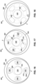
- an axial view aligned with axis 315 is shown to illustrate the relative positions of oscillating valve port section 340 and stationary valve port section 360. More specifically, each figure shows the port positions along the abutting faces of sections 340, 360 to illustrate the valve overlaps as oscillating valve port section 340 nutates with rotor 210 relative to the stationary position of stationary valve port section 360. Also, point P shows where sections 340, 360 contact, or most closely approach contact in each oscillating valve port section 340 position.
- Central port overlap 520 is defined as the open passage between central ports 350, 368, while first port overlap 522, second port overlap 524, third port overlap 526, and fourth port overlap 528 are defined between the plurality of oscillating valve ports 358 and stationary valve ports 372. As shown in Figure 16 , the areas between port overlaps 522, 524, 526, 528 may not be equal in some arrangements of ports 358, 372, and the relative magnitude of areas of port overlaps 522, 524, 526, 528 may vary as a function of oscillating valve port section 340 position, as shown for example in Figure 17 .
- Figure 17 shows a "partially open position" of valve section 300, wherein the total area for port overlaps 522, 524, 526, 528 is less than the maximum total area of the fully open position.
- Figure 18 shows a "fully closed position" of valve section 300, wherein no port overlaps 522, 524, 526, 528 are present.
- central port flow 508 in the deactivated condition, wherein dart 160 is not installed within rotor 210, bore flow 502 is greater than annulus flow 504 and thus central port flow 508 through central port overlap 520 is greater than valve port flow 510 through port overlaps 522, 524, 526, 528.
- central port flow 508 will still be larger than valve port flow 510 in the deactivated condition as annulus flow 504 has a higher pressure drop along rotor section 200 than does bore flow 502.
- a small annulus flow 504 results in only slight rotor 210 rotation, only slight variations in central port overlap 520, and thus only slight pressure pulses in downstream flow 512. Additionally, in some embodiments, even with rotor 210 rotation, central port overlap may be configured to have little or no area change with respect to rotor position. Flow 506 may also pass out of bore 348 and contribute to valve port flow 510, however, this flow will still not produce flow pulses, as this "bypass" flow will not rotate rotor 210, and thus will not vary port overlaps 522, 524, 526, 528.
- annulus flow 504 is increased relative to the deactivated condition.
- Annulus flow 504 leads to valve port flow 510 and intermittently diverts to flow 506 as port overlaps 522, 524, 526, 528 reduce in area.
- the diameter of orifice 354 may be adjusted to provide the appropriate "bypass" flow and in some embodiments, orifice 354 may be fully omitted.
- the magnitude of bore flow 502 depends on nozzle 140 selection and in some configurations may still be large as compared to annulus flow 504, thus central port flow 508 will also be comparatively large.
- central port overlap 520 may or may not contribute to the pressure pulses, depending on the relative sizes and positions of central ports 350, 368.
- embodiments disclosed herein include systems and methods for using a flow pulsing system which may be selectively engaged after wellbore drilling has begun, and while the drilling string remains disposed within the wellbore. Additionally, systems and methods disclosed herein allow selective adjustability of the flow pulsing system frequency and magnitude, as well as systems and methods to selectively disengage and/ or reconfigure the frequency and magnitude, while the flow pulsating system remains disposed within the wellbore. In this manner, the overall pressure loss through flow pulsing system 10 may be selectively controlled. Further, systems and methods disclosed herein provide valve ports which may be operated between a fully open, a partially open, and a fully closed position which may provide an improved pressure pulse response.
- valve port sections 340, 360 cycle through the open, partially open, and closed positions the oscillating valve portion section 340 nutates relative to the stationary valve port section 360. Still further, systems and methods disclosed herein resist clogging of the flow pulsing system when materials are introduced into the wellbore, such as loss circulation materials or diverter.
- screen 110 may have different shapes along screen housing 120 which are non-conical.
- screen elements 134 may be modified to comprise a plurality of thru holes such has circular through holes oriented radially.
- dart 160 may seal with rotor 210 with a different combination of bore sealing rings, such as ring 187, or may use face sealing rings between abutting annular shoulders. Such abutting shoulders may also be included to prevent or control the degree of taper locking between tip 184 and seat 222.
- flow pulsing system 10 may be provided in a constantly activated condition wherein dart 160 and nozzle 140 are not removable from bore 218 of rotor 210.
- dart 160 and nozzle 140 are not removable from bore 218 of rotor 210.
- such embodiments may be produced by welding dart 160 to rotor 210 or alternatively by omitting dart 160 and coupling nozzle 140 directly with rotor 210.
- Nozzle 140 may thus also be coupled irremovably with rotor 210 (e.g. welded) or may be produced as portion of rotor 210.
- the ports within oscillating valve 311 and/ or stationary valve 361 may be omitted, for example if a lobed outer profile is used, as the spaces between lobes could serve as ports.
- the embodiments described herein are exemplary only and are not limiting. Many variations and modifications of the systems, apparatus, and processes described herein are possible and are within the scope of the disclosure. Accordingly, the scope of protection is not limited to the embodiments described herein, but is only limited by the claims that follow, the scope of which shall include all equivalents of the subject matter of the claims. Unless expressly stated otherwise, the steps in a method claim may be performed in any order. The recitation of identifiers such as (a), (b), (c) or (1), (2), (3) before steps in a method claim are not intended to and do not specify a particular order to the steps, but rather are used to simplify subsequent reference to such steps.
Landscapes
- Engineering & Computer Science (AREA)
- Life Sciences & Earth Sciences (AREA)
- Geology (AREA)
- Mining & Mineral Resources (AREA)
- Environmental & Geological Engineering (AREA)
- Fluid Mechanics (AREA)
- Physics & Mathematics (AREA)
- General Life Sciences & Earth Sciences (AREA)
- Geochemistry & Mineralogy (AREA)
- Mechanical Engineering (AREA)
- Marine Sciences & Fisheries (AREA)
- Multiple-Way Valves (AREA)
- Sliding Valves (AREA)
Abstract
Description
- The disclosure relates generally to downhole apparatus. More particularly, the disclosure relates to drilling apparatus and drilling methods which include an agitator or flow pulsing apparatus in a drill string. Among other benefits, a flow pulsing apparatus may be used to oscillate a drill string to reduce friction with a borehole, to enhance tool face control, to extend borehole lengths, and to improve drilling efficiency. The flow pulsing apparatus may be used in other downhole work strings as well.
- Some embodiments disclosed herein are directed to a flow pulsing system. In an embodiment, the flow pulsing system includes a housing having a central axis, a first end, a second end opposite the first end, and a bore extending along the central axis from the first end to the second end. Additionally, some embodiments may include a stator disposed within the bore of the housing having a plurality of lobe cavities and a rotor disposed within the stator. The rotor includes an axis offset from the central axis, a plurality of lobes that mate with the plurality of lobe cavities, and a thru bore extending along the axis. Additionally, some embodiments may include a dart configured to releasably couple with the thru bore of the rotor, the dart including a first radially outer guide section, a second radially outer guide section, a tip, an inner bore, and a releasable nozzle configured to control a first fluid flow through the inner bore and the thru bore.
- Other embodiments disclosed herein are directed to a flow pulsing system including a housing having a central axis, a first end, a second end opposite the first end, and a bore extending along the central axis from the first end to the second end. Additionally, some embodiments may include a stator disposed within the bore of the housing having a plurality of lobe cavities and a rotor disposed within the stator. The rotor includes an axis offset from the central axis, a plurality of lobes that correspond with the plurality of lobe cavities, a thru bore extending along the axis. Additionally, some embodiments may include a screen disposed within the bore of the housing, the screen including a body and a coupling surface at a first end of the body, the coupling surface configured to couple to the housing. Additionally, some embodiments may include a screen housing extending to a second end of the body and an inner bore to fluidly communicate with the thru bore.
- Still other embodiments disclosed herein are directed to a flow pulsing system including a housing having a central axis, a first end, a second end opposite the first end, and a bore extending along the central axis from the first end to the second end. Additionally, some embodiments may include a stator disposed within the bore of the housing having a plurality of lobe cavities and a rotor disposed within the stator. The rotor includes an axis offset from the central axis, a plurality of lobes that mate with the plurality of lobe cavities, and a thru bore extending along the axis. Additionally, some embodiments may include a valve section including a stationary valve coupled to the second end of the housing, the stationary valve including a first face, a stationary central port, and a plurality of stationary valve ports. Additionally, some embodiments may include an oscillating valve coupled to the rotor, the oscillating valve including a second face abutting the first face, an oscillating central port in fluid communication with the thru bore of the rotor, and a plurality of oscillating valve ports in fluid communication with the plurality of lobe cavities.
- Embodiments described herein comprise a combination of features and characteristics intended to address various shortcomings associated with certain prior devices, systems, and methods. The foregoing has outlined rather broadly the features and technical characteristics of the disclosed embodiments in order that the detailed description that follows may be better understood. The various characteristics and features described above, as well as others, will be readily apparent to those skilled in the art upon reading the following detailed description, and by referring to the accompanying drawings. It should be appreciated that the conception and the specific embodiments disclosed may be readily utilized as a basis for modifying or designing other structures for carrying out the same purposes as the disclosed embodiments. It should also be realized that such equivalent constructions do not depart from the spirit and scope of the principles disclosed herein.
- For a detailed description of various exemplary embodiments, reference will now be made to the accompanying drawings in which:
-
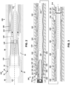
Figure 1 is a cross-sectional view of a flow pulsing apparatus, according to some embodiments; -
Figure 2 is a cross-sectional view of an activation section and partial cross-sectional view of a rotor section of the flow pulsing apparatus ofFigure 1 ; -
Figure 3 is a cross-sectional view of the rotor section of the flow pulsing apparatus ofFigure 1 ; -
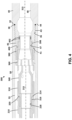
Figure 4 is a cross-sectional view of a valve section of the flow pulsing apparatus ofFigure 1 ; -
Figure 5 is a perspective view of a screen used within the activation section ofFigure 2 ; -
Figure 6 is a cross-sectional view of the screen ofFigure 5 ; -
Figure 7 is a perspective view of a dart and nozzle used within the activation section ofFigure 2 ; -
Figure 8 is a cross-sectional view of the dart and a nozzle ofFigure 7 ; -
Figure 9 is a cross-sectional view of the activation section and partial cross-sectional view of the rotor section in a deactivated condition; -
Figure 10 is perspective view of an oscillating valve used within the valve section ofFigure 4 ; -
Figure 11 is perspective view of a stationary valve used within the valve section ofFigure 4 ; -
Figure 12 is a cross-sectional view of the oscillating valve and stationary valve ofFigures 10 and 11 ; -
Figure 13 is a cross-sectional view of the activation section and a partial cross-sectional view of the rotor section, showing fluid flow in the deactivated condition; -
Figure 14 is a cross-sectional view of the activation section and a partial cross-sectional view of the rotor section, showing fluid flow therethrough in an activated condition; -
Figure 15 is a cross-sectional view of the valve section ofFigure 4 , showing fluid flow therethrough; -
Figure 16 is a schematic axial view of the oscillating valve and stationary valve interface, showing the overlap of ports in an open condition; -
Figure 17 is another schematic axial view of the oscillating valve and stationary valve interface, showing the overlap of ports in a partially open condition; and -
Figure 18 is another schematic axial view of the oscillating valve and stationary valve interface, showing the overlap of ports in a closed condition. - The following discussion is directed to various exemplary embodiments. However, one of ordinary skill in the art will understand that the examples disclosed herein have broad application, and that the discussion of any embodiment is meant only to be exemplary of that embodiment, and not intended to suggest that the scope of the disclosure, including the claims, is limited to that embodiment.
- The drawing figures are not necessarily to scale. Certain features and components herein may be shown exaggerated in scale or in somewhat schematic form and some details of conventional elements may not be shown in interest of clarity and conciseness.
- In the following discussion and in the claims, the terms "including" and "comprising" are used in an open-ended fashion, and thus should be interpreted to mean "including, but not limited to...." Also, the term "couple" or "couples" is intended to mean either an indirect or direct connection. Thus, if a first device couples to a second device, that connection may be through a direct connection of the two devices, or through an indirect connection that is established via other devices, components, nodes, and connections. In addition, as used herein, the terms "axial" and "axially" generally mean along or parallel to a given axis (e.g., central axis of a body or a port), while the terms "radial" and "radially" generally mean perpendicular to the given axis. For instance, an axial distance refers to a distance measured along or parallel to the axis, and a radial distance means a distance measured perpendicular to the axis.
- As previously described above, a flow pulsing system, otherwise referred to herein as an agitator, may be used along a drill string to introduce a pressure pulse or pressure wave within a tubular of the drill string. A flow pulsing system may be used alone or with other components to provide drilling benefits including enhanced tool face control, improved drilling efficiency, and may be used to introduce oscillations of the drill string. More particularly, one such additional component used with the flow pulsing system, may be a shock tool, which harnesses the pressure pulses from the flow pulsing system to induce oscillations along the longitudinal axis of the drill string. In some applications, such drill string oscillations may provide reduced friction within a borehole and may allow for extended drill string lengths. To operate the flow pulsing system, pumping pressure is required from the drilling rig, to overcome pressure drops across the flow pulsing system, thus it may be desirable to provide a flow pulsing system which may be selectively activated only once the drill string encounters downhole conditions where it is needed. Additionally, it may also be desirable to operate the flow pulsing system at a frequency and magnitude which is adjustable, which then allows for less overall pressure drop. Further, it may also be desirable to have a flow pulsing system which may be deactivated when it is no longer needed or deactivated and reconfigured to provide a modified pressure pulse which is better suited for yet another section of wellbore drilling. In addition to drill strings, the flow pulsing apparatus can be used on other downhole work or tubular strings.
- Accordingly, embodiments disclosed herein include systems and methods for using a flow pulsing system which may be selectively engaged after wellbore drilling has begun, and while the drill string is disposed within the wellbore. Additionally, embodiments disclosed herein include systems and methods to selectively adjust the frequency and magnitude of the flow pulsing system, as well as systems and methods to selectively disengage and/or reconfigure the frequency and magnitude of the flow pulsing system after its use within the wellbore. Further, systems and methods disclosed herein provide valve ports which may be operated between a fully open, a partially open, and a fully closed position which may provide an improved pressure pulse response. Still further, systems and methods disclosed herein resist clogging of the flow pulsing system when materials are introduced into the wellbore, such as loss circulation materials.
- Referring to
Figure 1 , aflow pulsing system 10 is shown coupled to afirst sub 20 and asecond sub 40, each aligned alongaxis 15.Flow pulsing system 10 includes ahousing 30 and comprises anactivation section 100, arotor section 200, and avalve section 300. Generally speakingflow pulsing system 10 is a tubular assembly which may be installed along any segment of a drill string within a wellbore (not shown). Exemplary connections along afirst end 21 offirst sub 20 and asecond end 42 ofsecond sub 40 are shown, which may each be modified as necessary to adapt with a particular drill string. Similarly,second end 22 of first sub 20 (Figure 9 ) andfirst end 41 of second sub 40 (Figure 4 ) may also be modified as needed to adapt withhousing 30 andflow pulsing system 10. - Referring to
Figure 2 ,activation section 100 is shown in more detail, which may be used withinflow pulsing system 10.Activation section 100 comprises anaxis 115 which is generally aligned withaxis 15 offlow pulsing system 10, anaxis 215 which is offset fromaxis 115, ascreen 110, and anozzle 140 installed within adart 160. More particularly,housing 30 has afirst end 31 and a second end 32 (shown inFigure 4 ) oppositefirst end 31, and abore 33 concentric withhousing 30, which both extend alongaxis 115 between ends 31, 32.Screen 110 is positioned alongaxis 115 proximatefirst end 31, whilenozzle 140 and dart 160 are positioned alongaxis 215 at a position betweenscreen 110 andsecond end 32. - Referring to
Figures 2 and 3 ,rotor section 200 is shown in more detail, which comprises arotor 210 aligned withaxis 215 and astator 230 aligned withaxis 115. In general,rotor 210 andstator 230 are tubular members housed withinbore 33 withrotor 210 positioned at least partially withinstator 230. More particularly,stator 230 includes afirst end 232 and asecond end 234 oppositefirst end 232 and includes a radiallyinner surface 236 which extends between ends 232, 234.Stator 230 is coupled tohousing 30 withinbore 33 at a position between ends 31, 32 and comprises a plurality oflobe cavities 240 axially spaced apart along radiallyinner surface 236. The plurality oflobe cavities 240 results in the diameter ofinner surface 236 sequentially expanding and contracting along the length ofstator 230.Rotor 210 is also a tubular member comprising afirst end 212, asecond end 214 oppositefirst end 212, abody 216, and abore 218.Body 216 and bore 218 are each aligned withaxis 215, and extend betweenends Rotor 210 further includes alobe 224 extending radially outward frombody 216, withlobe 224 arranged in a generally helical manner alongaxis 215 and extending betweenends Figures 2 and 3 , the helical pitch is selected such that a full 360-degree revolution oflobe 224 aboutaxis 215 coincides with the distance betweenlobe cavities 240. As described, a singlecontinuous lobe 224 is shown in this embodiment, however other embodiments may use multiple lobes arranged helically or may use multiple separate lobes which are not formed helically. In some embodiments,rotor 210 may have oneless lobe 224 than the quantity oflobe cavities 240 alongstator 230. In all instances,lobes 224 may be referred to as separate lobes, when viewed in cross-section as a short hand for discussing therotor 210 geometry. For example, inFigure 3 ,rotor 210 includes elevenlobes 224. The relative dimensions of radiallyinner surface 236,lobe cavities 240, andlobe 224 are selected such thatrotor 210 may be rotatably disposed withinstator 230. The radial clearance betweenlobe 224 andlobe cavity 240 definescavity 238. - Referring to
Figure 4 ,valve section 300 is shown in more detail, which comprises components aligned withaxis 215 ofrotor 210 and components aligned withaxis 315 which is generally aligned withaxis 15 offlow pulsing system 10. In general, the components aligned withaxis 215 are coupled torotor 210 and thus move withrotor 210 withinhousing 30, while components aligned withaxis 315 remain stationary relative tohousing 30 andsecond sub 40. More particularly,valve section 300 components aligned withaxis 215 compriseoscillating valve adapter 310 and oscillatingvalve port section 340. Additionally,valve section 300 components aligned withaxis 315 comprise stationaryvalve port section 360 andstationary valve adapter 380. - Referring to
Figures 5 and 6 ,screen 110 is shown in more detail and comprisesaxis 115,first end 112, andsecond end 114 oppositefirst end 112. Additionally,screen 110 comprises acoupling surface 116 extending alongaxis 115 fromfirst end 112, ascreen housing 120 extending alongaxis 115 fromsecond end 114, and abody 118 extending therebetween. In someembodiments coupling surface 116 includes threads and has a smaller diameter thanbody 118, andannular shoulder 132 creates a radial transition therebetween. Also,flats 119 may be provided alongbody 118 to allow torque application to the threads ofcoupling surface 116.Bore 122 extends fromfirst end 112, passing withincoupling surface 116 andbody 118, whileinner surface 123 extends fromsecond end 114 and passes withinscreen housing 120 to intersectbore 122.Chamfer 130 transitions betweeninner surface 123 and bore 122, whilechamfer 128 is included alongbore 122 atfirst end 112.Screen housing 120 andinner surface 123 are generally frustoconical in shape, having alarger inlet diameter 124 proximatefirst end 112 than anoutlet diameter 126 atsecond end 114.Screen housing 120 additionally includes screen elements orslots 134 which pass throughscreen housing 120. In this embodiment,screen elements 134 include a plurality of elongated passages which are distributed circumferentially aboutaxis 115, the elongated passages each having a long axis which is aligned withaxis 115. However, other embodiments may include differently shaped passages withinscreen element 134 which are arranged differently. (e.g., for example a plurality of circular passages extending radially relative to axis 115). - Referring to
Figures 7 and 8 , dart 160 is shown in more detail and is generally symmetric relative toaxis 215. More particularly, dart 160 comprises afirst end 162, asecond end 164 oppositefirst end 162, and a plurality of features extending axially alongaxis 215, including ahead 166 extending fromfirst end 162, aneck 168 extending fromhead 166, a first radiallyouter guide section 174proximate neck 168, a second radiallyouter guide section 182 proximatesecond end 164, and afrustoconical tip 184 which narrows towardssecond end 164. In this embodiment,head 166 has a larger diameter thanneck 168, and thus creates ashoulder 170 therebetween. Additionally, first radiallyouter guide section 174 and second radiallyouter guide section 182 have larger diameters than the surrounding sections ofdart 160 and thus include various diameter transitions. More particularly, in this embodiment, chamfer type transitions are used and includetransitions outer guide section 174 and second radiallyouter guide section 182 are spaced apart alongaxis 215 and arelief 178, having a reduced diameter, is provided therebetween. Additionally, first radiallyouter guide section 174 further includes agland 186 disposed along its outer cylindrical surface and accepts a ring 187 (e.g. such as an O-ring) therein. - With respect to the inner surfaces of
dart 160, dart 160 further comprises abore 188 extending fromsecond end 164 intoneck 168, aninner coupling surface 190 extending fromfirst end 162, and asecond bore 192 extending therebetween. In this embodiment,inner coupling surface 190 is threaded and has a larger diameter thansecond bore 192, thus ashoulder 194 is formed therebetween. - Referring still to
Figures 7 and 8 ,nozzle 140 is shown installed within thefirst end 162 ofdart 160. More specifically,nozzle 140 is axially symmetric aboutaxis 215 and comprises afirst end 142, a second end 144 oppositefirst end 142, and an outer coupling surface 146 extending betweenends 142, 144.Nozzle 140 further comprises drive 154 extending fromfirst end 142 and aninner nozzle profile 150 which extends between ends 142, 144. More particularly,inner nozzle profile 150 includes aninlet 148 atfirst end 142 and anoutlet 152 at second end 144. In this embodiment,inlet 148 has a smaller diameter thanoutlet 152 and thus may be considered a diffusing nozzle wherein a fluid passing frominlet 148 tooutlet 152 would experience a decrease in flowrate and an associated increase in pressure. However, inother embodiments inlet 148 may be provided with an equal or larger diameter thanoutlet 152. The diameter ofinlet 148,outlet 152, and the shape ofinner nozzle profile 150 will be offered in various combinations and sizes, as the fluid flow throughnozzle 140 will influence the flow withinflow pulsing system 10 along various sections, as will be discussed more fully below. - When
nozzle 140 is installed withindart 160, outer coupling surface 146 ofnozzle 140 couples withinner coupling surface 190 ofdart 160. Drive 154 may be used to apply torque to thread the segments together until second end 144 ofnozzle 140 abuts withshoulder 194 ofdart 160. Seals 196 (e.g., such as O-ring seals) may be provided along second end 144 to prevent fluid leakage around the perimeter ofnozzle 140, and/or alternative seals 196 (not shown) may be provided along other sections ofnozzle 140 as needed (e.g., proximatefirst end 142 of nozzle 140). - Referring to
Figure 9 ,activation section 100 is shown in the deactivated condition or position, whereindart 160 is not positioned withinrotor 210.First sub 20 is shown coupled tohousing 30 and to screen 110, with each aligned alongaxis 115. More particularly,first sub 20 includes anouter coupling surface 24 extending fromsecond end 22, which couples withinner coupling surface 34 ofhousing 30. Ashoulder 26 onfirst sub 20 abuts withfirst end 31 ofhousing 30 to limit the axial position therebetween, while aseal 29 provides bore sealing therebetween.First sub 20 further includes aninner coupling surface 28 which extends withinfirst sub 20 fromsecond end 22.Screen 110 couples withfirst sub 20 ascoupling surface 116 engagesinner coupling surface 28, and the axial position therebetween is established asannular shoulder 132 ofscreen 110 abutssecond end 22 offirst sub 20. As previously described,stator 230 is coupled within bore 33 ofhousing 30 at a fixed position, whilerotor 210 is housed withinstator 230.First end 212 ofrotor 210 is placed proximate tosecond end 114 ofscreen 110 and in some instances makes abutting contact therewith. - Referring to
Figures 10 and12 , oscillatingvalve 311 is shown which comprisesoscillating valve adapter 310 and oscillatingvalve port section 340. Generally speaking, oscillatingvalve port section 340 fits within oscillatingvalve adapter 310 to form oscillatingvalve 311. More particularly, oscillatingvalve adapter 310 comprises afirst end 312, asecond end 314 oppositefirst end 312 alongaxis 215, acoupling surface 316 extending fromfirst end 312, abody 318 extending fromsecond end 314, and anouter shoulder 320 extending radially therebetween. In some embodiments,coupling surface 316 may include threads. Additionally, thrubore 322 extends alongaxis 215 fromfirst end 312 to meet with asecond bore 324 which extends alongaxis 215 fromsecond end 314.Second bore 324 is a blind hole which terminates withinbody 318 to forminner shoulder 326. - Oscillating
valve port section 340 comprises afirst end 342, asecond end 344 oppositefirst end 342 alongaxis 215, and abody 346 which extends between ends 342, 344. More specifically,body 346 extends fromfirst end 342 with a constant diameter along a first region and then flares into an increased diameter proximatesecond end 344. Oscillatingvalve port section 340 further comprises abore 348 extending alongaxis 215 fromfirst end 342, which meets withcentral port 350, which extends alongaxis 215 fromsecond end 344.Transition 352 is provided betweenbore 348 andcentral port 350, and in this embodiment is formed in a frustoconical shape which reduces in diameter proximatesecond end 344.Orifice 354 is formed as a through hole inbody 346, which extends intobore 348 at an angle relative toaxis 215. In some embodiments,orifice 354 will be angled towards second end 344 (e.g., with radially inner portions positioned closer to second end 344), with portions oforifice 354 extending alongtransition 352. Oscillatingvalve ports 358 extend fromsecond end 344 and include aninlet 356 which extends to a radially outer surface ofbody 346. In some embodiments, oscillatingvalve port 358 extends axially relative toaxis 215, whileinlet 356 extends at an angle towards second end 344 (e.g., with radially inner portions positioned closer to second end 344). As best shown inFigure 10 , a plurality of oscillatingvalve ports 358 and a plurality ofinlets 356 may be provided alongsecond end 344, and may be distributed circumferentially relative toaxis 215. For example, in this embodiment, four oscillatingvalve ports 358 and fourinlets 356 are distributed at ninety degree intervals. - To form oscillating
valve 311, oscillatingvalve port section 340 is coupled to oscillatingvalve adapter 310. More particularly,body 346 of oscillatingvalve port section 340 is fit withinsecond bore 324 of oscillatingvalve adapter 310, withfirst end 342 of oscillatingvalve port section 340 abuttinginner shoulder 326 of oscillatingvalve adapter 310. In some embodiments, the fit betweensecond bore 324 andbody 346 may be a press fit, which requires relative heating between the surfaces during the assembly makeup. - Referring to
Figures 11 and12 stationary valve 361 is shown which comprises stationaryvalve port section 360 andstationary valve adapter 380. Generally speaking, stationaryvalve port section 360 fits withinstationary valve adapter 380 to formstationary valve 361. More particularly, stationaryvalve port section 360 comprises afirst end 362, asecond end 364 oppositefirst end 322 alongaxis 315, and abody 366 extending betweenends body 366 has a constant diameter section proximatesecond end 364, and then has an increased diameter alongfirst end 362. Additionally,central port 368 extends withinbody 366 fromfirst end 362 and meets withtaper 370 which extends fromsecond end 364. More specifically,taper 370 has a frustoconical profile which increases in diameter at positions axially away fromsecond end 364.Stationary valve ports 372 are provided alongfirst end 362 at positions offset fromaxis 315 which are distributed circumferentially relative to axis 315 (as best shown inFigure 11 ), and extend intobody 366 to meet with the inner cavity formed bytaper 370. In this embodiment, fourstationary valve ports 372 are provided and are distributed at ninety degree intervals.Stationary valve ports 372 may extend intobody 366 in a direction parallel toaxis 315 or may extend at an angle. For example,stationary valve ports 372 may converge towardsaxis 315 at positions proximate tosecond end 364. -
Stationary valve adapter 380 comprises afirst end 382, asecond end 384 oppositefirst end 382 alongaxis 315, abody 386 extending fromfirst end 382, aseal receiving portion 394 extending fromsecond end 384, and acoupling surface 398 extending therebetween. More particularly,body 386,coupling surface 398, andseal receiving portion 394 are each generally cylindrical features, symmetric aboutaxis 315, which are connected with radially oriented shoulders.Shoulder 400 is formed betweenbody 386 andcoupling surface 398, whileshoulder 396 is formed betweencoupling surface 398 andseal receiving portion 394. Annular grooves 401 (accepting seals 402) are formed withinseal receiving portion 394 proximate tosecond end 384, and are axially spaced alongaxis 315. In some embodiments,coupling surface 398 may include threads. Additionally,first bore 388 extends alongaxis 315 fromfirst end 382 and terminates withinbody 386 to forminner shoulder 390, whilesecond bore 392 extends alongaxis 315 fromsecond end 384 to intersectfirst bore 388. - To form
stationary valve 361, stationaryvalve port section 360 is coupled tostationary valve adapter 380. More particularly,body 366 of stationaryvalve port section 360 is fit withinfirst bore 388 ofstationary valve adapter 380, withsecond end 364 of stationaryvalve port section 360 abuttinginner shoulder 390 ofstationary valve adapter 380. In some embodiments, the fit betweenfirst bore 388 andbody 366 may be a press fit, which requires relative heating between the surfaces during the assembly makeup. - Referring to
Figures 4 and12 ,valve section 300houses oscillating valve 311 andstationary valve 361, within bore 33 ofhousing 30. As previously described generally,valve section 300 includesaxis 215, which coincides with themovable rotor 210 and astationary axis 315 which is concentric withhousing 30 andsecond sub 40. More particularly, oscillatingvalve 311 is aligned withaxis 215 as it couples torotor 210, whilestationary valve 361 is aligned withaxis 315 as it couples tosecond sub 40. In this manner, the offset ofaxis 215 fromaxis 315, and any other offset axes, may be referred to as "eccentric," such term also applying to components such asoscillating valve 311 andstationary valve 361 that are axially offset relative to each other. Couplingsurface 316 of oscillatingvalve 311, couples with oscillatingvalve coupling surface 228 ofrotor 210 assecond end 214 ofrotor 210 abuts withouter shoulder 320 of oscillatingvalve 311. -
Stationary valve 361 fits partially withinsecond sub 40 proximate tofirst end 41 ofsecond sub 40. More particularly, seals 402 ofstationary valve 361 seal along bore 48 ofsecond sub 40, asstationary valve 361 andsecond sub 40 engage alongsurfaces first end 41 andshoulder 400. - The flat faces along
second end 344 of oscillatingvalve 311 andfirst end 362 ofstationary valve 361, abut and generally seal during operations asrotor 210 applies thrust forces alongaxis 215. Additionally, asrotor 210 rotates withinstator 230, the rotor also undergoes a nutating motion, whereinaxis 215 moves in an elliptical or orbital pattern relative toaxis 315 based on eccentricity ofrotor 210 and the interacting lobes224 andlobe cavities 240. Given this combination of thrust and nutating motion imparted byrotor 210, sliding occurs at the flat abutting faces ofvalves oscillating valve 311 also nutates relative tostationary valve 361. As a shorthand herein, the nutating motion of components withinflow pulsing system 10, may alternatively be referred to as "rotating". Additionally, one having ordinary skill in the art will appreciate that the nutating motion may be modified (for example, by varying the dimensions ofrotor 210 and stator 230) without departing from the principle of operation disclosed herein. In some embodiments, the path ofaxis 215 will form a hypocycloid asrotor 210 rotates withinstator 230. - Referring to
Figure 13 ,activation section 100 is shown in a deactivated condition or position, whereindart 160 is not installed withinrotor 210. Generally speaking, in the deactivated condition,rotor 210 is only slowly rotating withinstator 230, and as a result,flow pulsing system 10 may only produce a small amount of pulsating flow. - During drilling operations, drilling mud may be introduced within the bore or annulus of a drill string (not shown) and impart
upstream flow 500 which extends fromfirst sub 20 intoactivation section 100.Upstream flow 500 flows generally alongaxis 115 and thus tends to continue this flow direction throughscreen 110 and pass largely as bore flow 502 intobore 218 withinrotor 210. Due to limited flow restrictions downstream ofbore flow 502, relatively small back pressures occur that impedebore flow 502, and in general, this deactivated condition may results in only 20 to 80 psi in pressure losses passing thoroughflow pulsing system 10 overall. Under some flow conditions, backpressure withinbore 218 ofrotor 210 may occur which will bias someannulus flow 504 throughscreen elements 134 ofscreen 110.Annulus flow 504 then progresses downstream moving betweenrotor 210 andstator 230, thereby causing some rotation ofrotor 210, even in the deactivated condition. The gap betweenscreen 110 androtor 210 is shown exaggerated for clarity, and may in application approach abutting contact, such that anyannulus flow 504 will pass throughscreen elements 134. This configuration may be helpful in preventing particulate clogging betweenrotor 210 andstator 230. For example, loss circulation materials withinupstream flow 500, will tend to be directed intobore 218, and away from the relatively smaller passages betweenrotor 210 andstator 230. Additionally, the tapered shape ofscreen housing 120 may tend to prevent clogging ofscreen elements 134, and may in effect be "self-cleaning". Also, the close positioning ofscreen 110 may offer an additional operational benefit forrotor section 200, asrotor 210 may be constrained from axial motion assecond end 114 ofscreen 110 abutsfirst end 212 ofrotor 210. During some flow conditions,rotor 210 may tend to "kick back" and thus apply thrust forces againstscreen 110, even whenscreen 110 is configured to maintain a clearance gap between ends 114, 212. - Referring to
Figure 14 ,activation section 100 is shown in an activated condition or position, whereindart 160 is installed withinrotor 210. In the activated condition, additionalupstream flow 500 is directed toannulus flow 504 to impart increased rotation ofrotor 210, which causesflow pulsing system 10 to produce an increased pulsing flow. The pulsing frequency and magnitude are related to the flow rate ofannulus flow 504, which is controllable in part by selecting aparticular nozzle 140 fordart 160. More particularly, whendart 160 is mated alongseat 222 ofrotor 210,ring 187 may seal alongsecond bore 220 ofrotor 210, and substantially all boreflow 502 throughrotor 210, will pass throughnozzle 140, and the back pressure (e.g., head loss or pressure drop through nozzle 140) will then drivelarger annulus flow 504, which spinsrotor 210 at a higher frequency. By providing a variety ofnozzle 140 configurations, users offlow pulsing system 10 are able to select a flow pulsing frequency and magnitude which are appropriate for the specific downhole conditions once the drill string is already in position within a partially drilled wellbore. Because the overall pressure losses throughflow pulsing system 10 tend to increase with increasedannulus flow 504, users offlow pulsing system 10 may select anozzle 140 with an inner nozzle profile 150 (as shown inFigure 8 ) that optimizes the flow pulsing frequency and amplitude while balancing the overall pressure drop acrossflow pulsing system 10. Additionally, the diameter of orifice 354 (Figure 12 ) and the drilling mud composition (e.g. weight and viscosity) may also be varied to influence the pulsing frequency and amplitude. This ability to balance theflow pulsing system 10 performance against the associated pressure drop may be advantageous during operations, as the exact flow pulsing frequency and amplitude needed may not be known or predicable ahead of drilling operations. Additionally, even if the user did prospectively know what frequency and amplitude was going to be needed, the on/off selectability may allow the users to only engageflow pulsing system 10 once it is needed, and thus preserving the pumping pressure requirements from the surface equipment on the drilling rig. - Additionally,
activation section 100 may be returned to the deactivated condition, as shown inFigure 13 , asdart 160 may be selectably disengaged fromseat 222 ofrotor 210. More particularly, a separate tool (e.g., a wireline tool or puller, not shown) may be used to grip dart 160 alongshoulder 170 and/orneck 168 and apply tensile forces to retrievedart 160. In some embodiments, a close proximity betweenfirst end 212 ofrotor 210 andsecond end 114 ofscreen 110 may be advantageous, as abutting contact therebetween may compressively resist the tensile forces applied to dart 160. After retrieval ofdart 160, drilling operations may continue without operatingflow pulsing system 10, thus reducing the overall pressure drop acrossflow pulsing system 10, ornozzle 140 ofdart 160 may be reconfigured to select a different flow pulsing frequency or magnitude than what was initially used. This sequential retrieval and reconfiguring ofdart 160 may be repeated as necessary during the drilling operations. - Referring to
Figure 15 ,valve section 300 is shown in a deactivated condition, whereindart 160 is not installed withinrotor 210. As previously described, in the deactivated condition, boreflow 502 is greater thanannulus flow 504, thus most of the totalupstream flow 500 is directed betweencentral ports central port flow 508 is defined betweencentral ports valve port section 340 and stationaryvalve port section 360, respectively.Valve port flow 510 is defined between oscillatingvalve ports 358 andstationary valve ports 372.Downstream flow 512 is defined as the flow exitingstationary valve adapter 380 and entering intosecond sub 40 and comprises the summation offlows Flow 506 is also shown passing throughorifice 354, which in some flow configurations, may provide a flow path betweenbore flow 502 andannulus flow 504. For example, as will be discussed more fully below, whennozzle 140 is directing flow toannulus flow 504 while a blockage exists betweenports valve port flow 510. - Referring to
Figures 16 - 18 , an axial view aligned withaxis 315 is shown to illustrate the relative positions of oscillatingvalve port section 340 and stationaryvalve port section 360. More specifically, each figure shows the port positions along the abutting faces ofsections valve port section 340 nutates withrotor 210 relative to the stationary position of stationaryvalve port section 360. Also, point P shows wheresections valve port section 340 position. Central port overlap 520 is defined as the open passage betweencentral ports first port overlap 522,second port overlap 524,third port overlap 526, andfourth port overlap 528 are defined between the plurality of oscillatingvalve ports 358 andstationary valve ports 372. As shown inFigure 16 , the areas between port overlaps 522, 524, 526, 528 may not be equal in some arrangements ofports valve port section 340 position, as shown for example inFigure 17 . Overall, the summation of areas of port overlaps 522, 524, 526, 528 influences valve port flow 510 (as shown inFigure 15 ), while the area of central port overlap 520 influences central port flow 508 (as shown inFigure 15 ). Together, the change of port overlaps 522, 524, 526, 528 andcentral port overlap 520, with respect torotor 210 position (e.g., with respect to time) creates periodic flow pressure pulses indownstream flow 512.Figure 16 shows a position having a maximum total area for port overlaps 522, 524, 526, 528, which may alternatively be referred to a "fully open position" ofvalve section 300.Figure 17 shows a "partially open position" ofvalve section 300, wherein the total area for port overlaps 522, 524, 526, 528 is less than the maximum total area of the fully open position.Figure 18 shows a "fully closed position" ofvalve section 300, wherein no port overlaps 522, 524, 526, 528 are present. - Referring to
Figures 15 - 18 , in the deactivated condition, whereindart 160 is not installed withinrotor 210, boreflow 502 is greater thanannulus flow 504 and thuscentral port flow 508 throughcentral port overlap 520 is greater thanvalve port flow 510 through port overlaps 522, 524, 526, 528. Despite comparable flow areas forcentral port flow 508 andvalve port flow 510 throughvalve section 300 in some embodiments,central port flow 508 will still be larger thanvalve port flow 510 in the deactivated condition asannulus flow 504 has a higher pressure drop alongrotor section 200 than does boreflow 502. Asmall annulus flow 504 results in onlyslight rotor 210 rotation, only slight variations incentral port overlap 520, and thus only slight pressure pulses indownstream flow 512. Additionally, in some embodiments, even withrotor 210 rotation, central port overlap may be configured to have little or no area change with respect to rotor position. Flow 506 may also pass out ofbore 348 and contribute tovalve port flow 510, however, this flow will still not produce flow pulses, as this "bypass" flow will not rotaterotor 210, and thus will not vary port overlaps 522, 524, 526, 528. - Referring still to
Figures 15 - 18 , afteractivation section 100 is in the activated condition, withdart 160 installed withinrotor 210,annulus flow 504 is increased relative to the deactivated condition.Annulus flow 504 leads tovalve port flow 510 and intermittently diverts to flow 506 as port overlaps 522, 524, 526, 528 reduce in area. The diameter oforifice 354 may be adjusted to provide the appropriate "bypass" flow and in some embodiments,orifice 354 may be fully omitted. As previously described, the magnitude ofbore flow 502 depends onnozzle 140 selection and in some configurations may still be large as compared toannulus flow 504, thuscentral port flow 508 will also be comparatively large. In this configuration,central port overlap 520 may or may not contribute to the pressure pulses, depending on the relative sizes and positions ofcentral ports - In the manner described, embodiments disclosed herein include systems and methods for using a flow pulsing system which may be selectively engaged after wellbore drilling has begun, and while the drilling string remains disposed within the wellbore. Additionally, systems and methods disclosed herein allow selective adjustability of the flow pulsing system frequency and magnitude, as well as systems and methods to selectively disengage and/ or reconfigure the frequency and magnitude, while the flow pulsating system remains disposed within the wellbore. In this manner, the overall pressure loss through
flow pulsing system 10 may be selectively controlled. Further, systems and methods disclosed herein provide valve ports which may be operated between a fully open, a partially open, and a fully closed position which may provide an improved pressure pulse response. As thevalve port sections valve portion section 340 nutates relative to the stationaryvalve port section 360. Still further, systems and methods disclosed herein resist clogging of the flow pulsing system when materials are introduced into the wellbore, such as loss circulation materials or diverter. - While exemplary embodiments have been shown and described, modifications thereof can be made by one skilled in the art without departing from the scope or teachings herein. For example it is anticipated that
screen 110 may have different shapes alongscreen housing 120 which are non-conical. Additionally,screen elements 134 may be modified to comprise a plurality of thru holes such has circular through holes oriented radially. It is also anticipated thatdart 160 may seal withrotor 210 with a different combination of bore sealing rings, such asring 187, or may use face sealing rings between abutting annular shoulders. Such abutting shoulders may also be included to prevent or control the degree of taper locking betweentip 184 andseat 222. Additionally, it is anticipated thatflow pulsing system 10 may be provided in a constantly activated condition whereindart 160 andnozzle 140 are not removable frombore 218 ofrotor 210. For example, such embodiments may be produced by weldingdart 160 torotor 210 or alternatively by omittingdart 160 andcoupling nozzle 140 directly withrotor 210.Nozzle 140 may thus also be coupled irremovably with rotor 210 (e.g. welded) or may be produced as portion ofrotor 210. Alternative shapes and arrangements of ports within oscillatingvalve 311 andstationary valve 361 are anticipated, as the diameter oforifice 354 and the overlaps, such ascentral port overlap 520 and overlaps 522, 524, 526, 528, will control the "shape" of the pressure pulse produced on an amplitude verses time plot. For example a port overlap having a large rate of change with respect to time, may produce a pressure pulse shape which approaches a square wave, also having a large rate of change with respect to time, while port overlaps which vary more slowly may produce a pressure pulse shape which is more gradually varying. These pressure pulse shapes may thus be tailored to maximize shock tool performance, while also optimizing stresses imparted to pumping equipment and to mechanical components within the drilling string. Additionally, the ports within oscillatingvalve 311 and/ orstationary valve 361 may be omitted, for example if a lobed outer profile is used, as the spaces between lobes could serve as ports. Thus, the embodiments described herein are exemplary only and are not limiting. Many variations and modifications of the systems, apparatus, and processes described herein are possible and are within the scope of the disclosure. Accordingly, the scope of protection is not limited to the embodiments described herein, but is only limited by the claims that follow, the scope of which shall include all equivalents of the subject matter of the claims. Unless expressly stated otherwise, the steps in a method claim may be performed in any order. The recitation of identifiers such as (a), (b), (c) or (1), (2), (3) before steps in a method claim are not intended to and do not specify a particular order to the steps, but rather are used to simplify subsequent reference to such steps. - The following numbered clauses on pages 18 to 21 of the present description correspond to the claims of
European patent application no. 20843889.5 European patent application no. 20843889.5 subsequent pages 22 to 24 of the specification which begin with the heading "CLAIMS". -
- 1. A flow pulsing system comprising:
- a housing having a central axis, a first end, a second end opposite the first end, and a bore extending along the central axis from the first end to the second end;
- a stator disposed within the bore of the housing having a plurality of lobe cavities;
- a rotor disposed within the stator, the rotor comprising:
- an axis offset from the central axis;
- a plurality of lobes that mate with the plurality of lobe cavities; and
- a thru bore extending along the axis; and
- a dart configured to releasably couple with the thru bore of the rotor, the dart comprising:
- a first radially outer guide section;
- a second radially outer guide section;
- a tip;
- an inner bore; and
- a releasable nozzle configured to control a first fluid flow through the inner bore and the thru bore.
- 2. The flow pulsing system of clause 1, wherein the rotor further includes a seat within the thru bore, wherein the seat is configured to engage with the tip of the dart.
- 3. The flow pulsing system of clause 1, wherein the nozzle couples with the dart along an inner coupling surface of the dart.
- 4. The flow pulsing system of clause 3, wherein the nozzle is configured to direct the first fluid flow to a path between the plurality of lobe cavities of the stator and the plurality of lobes along the rotor and bypass a second fluid flow into the thru bore of the rotor.
- 5. The flow pulsing system of clause 4, further comprising a first position wherein the dart is located at a surface of a well, and a second position wherein the dart is releasably coupled with the rotor in a downhole location.
- 6. The flow pulsing system of clause 5, wherein a wireline or puller tool is used to disengage the tip of the dart from the seat of the rotor to increase the first fluid flow into the thru bore of the rotor.
- 7. A flow pulsing system comprising:
- a housing having a central axis, a first end, a second end opposite the first end, and a bore extending along the central axis from the first end to the second end;
- a stator disposed within the bore of the housing having a plurality of lobe cavities;
- a rotor disposed within the stator, the rotor comprising:
- an axis offset from the central axis;
- a plurality of lobes that correspond with the plurality of lobe cavities; and
- a thru bore extending along the axis; and
- a screen disposed within the bore of the housing, the screen comprising:
- a body;
- a coupling surface at a first end of the body, the coupling surface configured to couple to the housing;
- a screen housing extending to a second end of the body; and
- an inner bore to fluidly communicate with the thru bore.
- 8. The flow pulsing system of clause 7, wherein the screen housing has a frustoconical shape and includes screen elements formed as slots aligned with the housing central axis.
- 9. The flow pulsing system of clause 7, wherein the second end of the screen is configured to intermittently contact the rotor thereby limiting motion of the rotor toward the first end of the housing.
- 10. The flow pulsing system of clause 7, wherein the inner bore of the screen is configured to receive a dart.
- 11. The flow pulsing system of
clause 10, wherein the dart is seatable in the rotor. - 12. The flow pulsing system of clause 11, wherein, when the dart is seated in the rotor, an end of the dart is disposed in the inner bore of the screen.
- 13. The flow pulsing system of clause 11, wherein, when the dart is seated in the rotor, the housing bore, the inner bore of the screen, the screen housing, an inner bore of the dart, and the thru bore of the rotor are in fluid communication.
- 14. A flow pulsing system comprising:
- a housing having a central axis, a first end, a second end opposite the first end, and a bore extending along the central axis from the first end to the second end;
- a stator disposed within the bore of the housing having a plurality of lobe cavities;
- a rotor disposed within the stator, the rotor comprising:
- an axis offset from the central axis;
- a plurality of lobes that mate with the plurality of lobe cavities; and
- a thru bore extending along the axis; and
- a valve section comprising:
- a stationary valve coupled to the second end of the housing, the stationary valve comprising a first face, a stationary central port, and a plurality of stationary valve ports;
- an oscillating valve coupled to the rotor, the oscillating valve comprising a second face abutting the first face, an oscillating central port in fluid communication with the thru bore of the rotor, and a plurality of oscillating valve ports in fluid communication with the plurality of lobe cavities.
- 15. The flow pulsing system of clause 14, wherein the position of the oscillating valve relative to the stationary valve creates:
- a central port overlap between the central port of the stationary valve and the central port of the oscillating valve; and
- a first port overlap between one of the plurality of stationary valve ports and one of the plurality of oscillating valve ports, wherein the motion of the rotor varies the first port overlap between a fully open position and a fully closed position.
- 16. The flow pulsing system of
clause 15, further including a second port overlap between another one of the plurality of stationary valve ports and another one of the plurality of oscillating valve ports, wherein the first port overlap and second port overlap have different areas at an intermediate position of the rotor, the intermediate position occurring between the fully open and the fully closed position. - 17. The flow pulsing system of clause 14, wherein the rotor is moveable to move the oscillating valve relative to the stationary valve.
- 18. The flow pulsing system of clause 17, wherein rotor motion causes a nutating motion of the oscillating valve relative to the stationary valve.
- 19. The flow pulsing system of clause 17, wherein rotor motion causes an eccentric motion of the oscillating valve relative to the stationary valve.
- 20. The flow pulsing system of clause 19, wherein the oscillating central port and the oscillating valve ports rotate eccentrically relative to the stationary central port and the stationary valve ports.
- 21. The flow pulsing system of clause 14, further comprising a releasable nozzle coupled to the rotor and configured to control a first fluid flow through the thru bore of the rotor.
- 22. The flow pulsing system of
clause 21, further comprising a dart which is configured to releasably couple with a seat within the thru bore of the rotor, the dart including an inner coupling surface along an inner bore which threadably couples with the releasable nozzle; and
wherein the releasable nozzle is further configured to control a second fluid flow along a path between the plurality of lobe cavities of the stator and the plurality of lobes along the rotor.
Claims (15)
- A flow pulsing system comprising:a housing having a central axis, a first end, a second end opposite the first end, and a bore extending along the central axis from the first end to the second end;a stator disposed within the bore of the housing having a plurality of lobe cavities;a rotor disposed within the stator, the rotor comprising:an axis offset from the central axis;a plurality of lobes that mate with the plurality of lobe cavities; anda thru bore extending along the axis; anda dart configured to releasably couple with the thru bore of the rotor, the dart comprising:a first radially outer guide section;a second radially outer guide section;a tip;an inner bore; anda releasable nozzle configured to control a first fluid flow through the inner bore and the thru bore.
- The flow pulsing system of claim 1, wherein the rotor further includes a seat within the thru bore, wherein the seat is configured to engage with the tip of the dart.
- The flow pulsing system of any preceding claim, wherein the nozzle couples with the dart along an inner coupling surface of the dart.
- The flow pulsing system of any preceding claim, wherein the nozzle is configured to direct the first fluid flow to a path between the plurality of lobe cavities of the stator and the plurality of lobes along the rotor and bypass a second fluid flow into the thru bore of the rotor.
- The flow pulsing system of any preceding claim, further comprising a first position wherein the dart is located at a surface of a well, and a second position wherein the dart is releasably coupled with the rotor in a downhole location.
- The flow pulsing system of claims 2 to 5, wherein a wireline or puller tool is used to disengage the tip of the dart from the seat of the rotor to increase the first fluid flow into the thru bore of the rotor.
- The flow pulsing system of any preceding claim further comprising:
a screen disposed within the bore of the housing, the screen comprising:a body;a coupling surface at a first end of the body, the coupling surface configured to couple to the housing;a screen housing extending to a second end of the body; andan inner bore to fluidly communicate with the thru bore. - The flow pulsing system of claim 7, wherein the screen housing has a frustoconical shape and includes screen elements formed as slots aligned with the housing central axis.
- The flow pulsing system of claim 7 or 8, wherein the second end of the screen is configured to intermittently contact the rotor thereby limiting motion of the rotor toward the first end of the housing.
- The flow pulsing system of claims 7 to 9, wherein the inner bore of the screen is configured to receive the dart.
- The flow pulsing system of any preceding claim comprising:
a valve section comprising:a stationary valve coupled to the second end of the housing, the stationary valve comprising a first face, a stationary central port, and a plurality of stationary valve ports;an oscillating valve coupled to the rotor, the oscillating valve comprising a second face abutting the first face, an oscillating central port in fluid communication with the thru bore of the rotor, and a plurality of oscillating valve ports in fluid communication with the plurality of lobe cavities. - The flow pulsing system of claim 11, wherein the rotor is moveable to move the oscillating valve relative to the stationary valve.
- The flow pulsing system of claim 12, wherein rotor motion causes a nutating motion of the oscillating valve relative to the stationary valve.
- The flow pulsing system of claim 12, wherein rotor motion causes an eccentric motion of the oscillating valve relative to the stationary valve.
- The flow pulsing system of claim 11, wherein the oscillating central port and the oscillating valve ports rotate eccentrically relative to the stationary central port and the stationary valve ports.
Applications Claiming Priority (3)
| Application Number | Priority Date | Filing Date | Title |
|---|---|---|---|
| US201962877168P | 2019-07-22 | 2019-07-22 | |
| EP20843889.5A EP4004328B1 (en) | 2019-07-22 | 2020-07-21 | On demand flow pulsing system |
| PCT/US2020/042943 WO2021016282A1 (en) | 2019-07-22 | 2020-07-21 | On demand flow pulsing system |
Related Parent Applications (2)
| Application Number | Title | Priority Date | Filing Date |
|---|---|---|---|
| EP20843889.5A Division EP4004328B1 (en) | 2019-07-22 | 2020-07-21 | On demand flow pulsing system |
| EP20843889.5A Division-Into EP4004328B1 (en) | 2019-07-22 | 2020-07-21 | On demand flow pulsing system |
Publications (3)
| Publication Number | Publication Date |
|---|---|
| EP4435227A2 true EP4435227A2 (en) | 2024-09-25 |
| EP4435227A3 EP4435227A3 (en) | 2024-10-30 |
| EP4435227B1 EP4435227B1 (en) | 2025-10-29 |
Family
ID=74194202
Family Applications (2)
| Application Number | Title | Priority Date | Filing Date |
|---|---|---|---|
| EP20843889.5A Active EP4004328B1 (en) | 2019-07-22 | 2020-07-21 | On demand flow pulsing system |
| EP24192982.7A Active EP4435227B1 (en) | 2019-07-22 | 2020-07-21 | On demand flow pulsing system |
Family Applications Before (1)
| Application Number | Title | Priority Date | Filing Date |
|---|---|---|---|
| EP20843889.5A Active EP4004328B1 (en) | 2019-07-22 | 2020-07-21 | On demand flow pulsing system |
Country Status (5)
| Country | Link |
|---|---|
| US (1) | US12618292B2 (en) |
| EP (2) | EP4004328B1 (en) |
| CN (1) | CN114207245A (en) |
| CA (2) | CA3293239A1 (en) |
| WO (1) | WO2021016282A1 (en) |
Families Citing this family (2)
| Publication number | Priority date | Publication date | Assignee | Title |
|---|---|---|---|---|
| US11480020B1 (en) * | 2021-05-03 | 2022-10-25 | Arrival Energy Solutions Inc. | Downhole tool activation and deactivation system |
| CN114809923A (en) * | 2022-04-12 | 2022-07-29 | 中海油田服务股份有限公司 | Hydraulic oscillator |
Family Cites Families (14)
| Publication number | Priority date | Publication date | Assignee | Title |
|---|---|---|---|---|
| US4462469A (en) * | 1981-07-20 | 1984-07-31 | Amf Inc. | Fluid motor and telemetry system |
| CA1217759A (en) * | 1983-07-08 | 1987-02-10 | Intech Oil Tools Ltd. | Drilling equipment |
| US6279670B1 (en) * | 1996-05-18 | 2001-08-28 | Andergauge Limited | Downhole flow pulsing apparatus |
| GB0324744D0 (en) * | 2003-10-23 | 2003-11-26 | Andergauge Ltd | Running and cementing tubing |
| GB0613637D0 (en) | 2006-07-08 | 2006-08-16 | Andergauge Ltd | Selective agitation of downhole apparatus |
| US7938200B2 (en) * | 2007-11-29 | 2011-05-10 | Smith International, Inc. | Apparatus and method for a hydraulic diaphragm downhole mud motor |
| GB0919649D0 (en) * | 2009-11-10 | 2009-12-23 | Nat Oilwell Varco Lp | Downhole tractor |
| US20140102804A1 (en) | 2012-10-15 | 2014-04-17 | Bbj Tools Inc. | Agitator sub |
| US20140190749A1 (en) * | 2012-12-13 | 2014-07-10 | Acura Machine Inc. | Downhole drilling tool |
| US9273529B2 (en) | 2013-09-13 | 2016-03-01 | National Oilwell Varco, L.P. | Downhole pulse generating device |
| US9765584B2 (en) * | 2013-12-03 | 2017-09-19 | Tll Oilfield Consulting Ltd. | Flow controlling downhole tool |
| CA3029872A1 (en) | 2016-07-07 | 2018-01-11 | Impulse Downhole Solutions Ltd. | Flow-through pulsing assembly for use in downhole operations |
| AU2018243929B2 (en) * | 2017-03-28 | 2022-07-07 | National Oilwell Varco, LP. | Valves for actuating downhole shock tools in connection with concentric drive systems |
| US10590709B2 (en) * | 2017-07-18 | 2020-03-17 | Reme Technologies Llc | Downhole oscillation apparatus |
-
2020
- 2020-07-21 CA CA3293239A patent/CA3293239A1/en active Pending
- 2020-07-21 WO PCT/US2020/042943 patent/WO2021016282A1/en not_active Ceased
- 2020-07-21 EP EP20843889.5A patent/EP4004328B1/en active Active
- 2020-07-21 US US17/629,057 patent/US12618292B2/en active Active
- 2020-07-21 CA CA3148449A patent/CA3148449C/en active Active
- 2020-07-21 CN CN202080053090.4A patent/CN114207245A/en active Pending
- 2020-07-21 EP EP24192982.7A patent/EP4435227B1/en active Active
Also Published As
| Publication number | Publication date |
|---|---|
| EP4435227B1 (en) | 2025-10-29 |
| WO2021016282A1 (en) | 2021-01-28 |
| US12618292B2 (en) | 2026-05-05 |
| EP4004328A4 (en) | 2023-08-23 |
| CN114207245A (en) | 2022-03-18 |
| EP4435227A3 (en) | 2024-10-30 |
| EP4004328A1 (en) | 2022-06-01 |
| CA3293239A1 (en) | 2026-03-02 |
| US20220275685A1 (en) | 2022-09-01 |
| EP4004328B1 (en) | 2024-09-11 |
| CA3148449A1 (en) | 2021-01-28 |
| CA3148449C (en) | 2026-03-31 |
Similar Documents
| Publication | Publication Date | Title |
|---|---|---|
| US11091959B2 (en) | Downhole oscillation apparatus | |
| US10876367B2 (en) | Downhole vibratory apparatus | |
| US11002099B2 (en) | Valves for actuating downhole shock tools in connection with concentric drive systems | |
| US10724323B2 (en) | Downhole vibration tool for drill string | |
| EP4004328B1 (en) | On demand flow pulsing system | |
| US12509945B2 (en) | Rotary steerable system | |
| CN121152918A (en) | Selective activation of friction reduction tools and methods | |
| US20250270888A1 (en) | Selectively activated friction reduction tool and method | |
| RU2854659C1 (en) | Device and method for creating adjustable pressure pulse for imparting vibration to downhole drill string | |
| US12631082B1 (en) | Rotary flow control apparatus |
Legal Events
| Date | Code | Title | Description |
|---|---|---|---|
| PUAI | Public reference made under article 153(3) epc to a published international application that has entered the european phase |
Free format text: ORIGINAL CODE: 0009012 |
|
| STAA | Information on the status of an ep patent application or granted ep patent |
Free format text: STATUS: THE APPLICATION HAS BEEN PUBLISHED |
|
| AC | Divisional application: reference to earlier application |
Ref document number: 4004328 Country of ref document: EP Kind code of ref document: P |
|
| AK | Designated contracting states |
Kind code of ref document: A2 Designated state(s): AL AT BE BG CH CY CZ DE DK EE ES FI FR GB GR HR HU IE IS IT LI LT LU LV MC MK MT NL NO PL PT RO RS SE SI SK SM TR |
|
| PUAL | Search report despatched |
Free format text: ORIGINAL CODE: 0009013 |
|
| AK | Designated contracting states |
Kind code of ref document: A3 Designated state(s): AL AT BE BG CH CY CZ DE DK EE ES FI FR GB GR HR HU IE IS IT LI LT LU LV MC MK MT NL NO PL PT RO RS SE SI SK SM TR |
|
| RIC1 | Information provided on ipc code assigned before grant |
Ipc: E21B 31/00 20060101ALI20240925BHEP Ipc: E21B 21/10 20060101ALI20240925BHEP Ipc: E21B 7/24 20060101ALI20240925BHEP Ipc: E21B 4/02 20060101ALI20240925BHEP Ipc: E21B 34/14 20060101AFI20240925BHEP |
|
| STAA | Information on the status of an ep patent application or granted ep patent |
Free format text: STATUS: REQUEST FOR EXAMINATION WAS MADE |
|
| 17P | Request for examination filed |
Effective date: 20250417 |
|
| GRAP | Despatch of communication of intention to grant a patent |
Free format text: ORIGINAL CODE: EPIDOSNIGR1 |
|
| STAA | Information on the status of an ep patent application or granted ep patent |
Free format text: STATUS: GRANT OF PATENT IS INTENDED |
|
| RIC1 | Information provided on ipc code assigned before grant |
Ipc: E21B 31/00 20060101ALI20250505BHEP Ipc: E21B 21/10 20060101ALI20250505BHEP Ipc: E21B 7/24 20060101ALI20250505BHEP Ipc: E21B 4/02 20060101ALI20250505BHEP Ipc: E21B 34/14 20060101AFI20250505BHEP |
|
| INTG | Intention to grant announced |
Effective date: 20250522 |
|
| GRAS | Grant fee paid |
Free format text: ORIGINAL CODE: EPIDOSNIGR3 |
|
| GRAA | (expected) grant |
Free format text: ORIGINAL CODE: 0009210 |
|
| STAA | Information on the status of an ep patent application or granted ep patent |
Free format text: STATUS: THE PATENT HAS BEEN GRANTED |
|
| AC | Divisional application: reference to earlier application |
Ref document number: 4004328 Country of ref document: EP Kind code of ref document: P |
|
| AK | Designated contracting states |
Kind code of ref document: B1 Designated state(s): AL AT BE BG CH CY CZ DE DK EE ES FI FR GB GR HR HU IE IS IT LI LT LU LV MC MK MT NL NO PL PT RO RS SE SI SK SM TR |
|
| REG | Reference to a national code |
Ref country code: CH Ref legal event code: F10 Free format text: ST27 STATUS EVENT CODE: U-0-0-F10-F00 (AS PROVIDED BY THE NATIONAL OFFICE) Effective date: 20251029 Ref country code: GB Ref legal event code: FG4D |
|
| REG | Reference to a national code |
Ref country code: DE Ref legal event code: R096 Ref document number: 602020061523 Country of ref document: DE |
|
| REG | Reference to a national code |
Ref country code: IE Ref legal event code: FG4D |
|
| REG | Reference to a national code |
Ref country code: NL Ref legal event code: FP |
|
| P01 | Opt-out of the competence of the unified patent court (upc) registered |
Free format text: CASE NUMBER: UPC_APP_0019614_4435227/2025 Effective date: 20251230 |
|
| PG25 | Lapsed in a contracting state [announced via postgrant information from national office to epo] |
Ref country code: ES Free format text: LAPSE BECAUSE OF FAILURE TO SUBMIT A TRANSLATION OF THE DESCRIPTION OR TO PAY THE FEE WITHIN THE PRESCRIBED TIME-LIMIT Effective date: 20251029 |
|
| REG | Reference to a national code |
Ref country code: LT Ref legal event code: MG9D |
|
| PG25 | Lapsed in a contracting state [announced via postgrant information from national office to epo] |
Ref country code: AT Free format text: LAPSE BECAUSE OF FAILURE TO SUBMIT A TRANSLATION OF THE DESCRIPTION OR TO PAY THE FEE WITHIN THE PRESCRIBED TIME-LIMIT Effective date: 20251029 Ref country code: HR Free format text: LAPSE BECAUSE OF FAILURE TO SUBMIT A TRANSLATION OF THE DESCRIPTION OR TO PAY THE FEE WITHIN THE PRESCRIBED TIME-LIMIT Effective date: 20251029 Ref country code: FI Free format text: LAPSE BECAUSE OF FAILURE TO SUBMIT A TRANSLATION OF THE DESCRIPTION OR TO PAY THE FEE WITHIN THE PRESCRIBED TIME-LIMIT Effective date: 20251029 |
|
| REG | Reference to a national code |
Ref country code: AT Ref legal event code: MK05 Ref document number: 1851762 Country of ref document: AT Kind code of ref document: T Effective date: 20251029 |
|
| PG25 | Lapsed in a contracting state [announced via postgrant information from national office to epo] |
Ref country code: RS Free format text: LAPSE BECAUSE OF FAILURE TO SUBMIT A TRANSLATION OF THE DESCRIPTION OR TO PAY THE FEE WITHIN THE PRESCRIBED TIME-LIMIT Effective date: 20260129 |
|
| PG25 | Lapsed in a contracting state [announced via postgrant information from national office to epo] |
Ref country code: IS Free format text: LAPSE BECAUSE OF FAILURE TO SUBMIT A TRANSLATION OF THE DESCRIPTION OR TO PAY THE FEE WITHIN THE PRESCRIBED TIME-LIMIT Effective date: 20260228 |
|
| PG25 | Lapsed in a contracting state [announced via postgrant information from national office to epo] |
Ref country code: PT Free format text: LAPSE BECAUSE OF FAILURE TO SUBMIT A TRANSLATION OF THE DESCRIPTION OR TO PAY THE FEE WITHIN THE PRESCRIBED TIME-LIMIT Effective date: 20260302 |
|
| PG25 | Lapsed in a contracting state [announced via postgrant information from national office to epo] |
Ref country code: PL Free format text: LAPSE BECAUSE OF FAILURE TO SUBMIT A TRANSLATION OF THE DESCRIPTION OR TO PAY THE FEE WITHIN THE PRESCRIBED TIME-LIMIT Effective date: 20251029 |
|
| PG25 | Lapsed in a contracting state [announced via postgrant information from national office to epo] |
Ref country code: LV Free format text: LAPSE BECAUSE OF FAILURE TO SUBMIT A TRANSLATION OF THE DESCRIPTION OR TO PAY THE FEE WITHIN THE PRESCRIBED TIME-LIMIT Effective date: 20251029 |
|
| PG25 | Lapsed in a contracting state [announced via postgrant information from national office to epo] |
Ref country code: BG Free format text: LAPSE BECAUSE OF FAILURE TO SUBMIT A TRANSLATION OF THE DESCRIPTION OR TO PAY THE FEE WITHIN THE PRESCRIBED TIME-LIMIT Effective date: 20251029 |