EP4435170A1 - A household appliance - Google Patents
A household appliance Download PDFInfo
- Publication number
- EP4435170A1 EP4435170A1 EP24160423.0A EP24160423A EP4435170A1 EP 4435170 A1 EP4435170 A1 EP 4435170A1 EP 24160423 A EP24160423 A EP 24160423A EP 4435170 A1 EP4435170 A1 EP 4435170A1
- Authority
- EP
- European Patent Office
- Prior art keywords
- support member
- fan
- household appliance
- frame
- blades
- Prior art date
- Legal status (The legal status is an assumption and is not a legal conclusion. Google has not performed a legal analysis and makes no representation as to the accuracy of the status listed.)
- Granted
Links
Images


Classifications
-
- D—TEXTILES; PAPER
- D06—TREATMENT OF TEXTILES OR THE LIKE; LAUNDERING; FLEXIBLE MATERIALS NOT OTHERWISE PROVIDED FOR
- D06F—LAUNDERING, DRYING, IRONING, PRESSING OR FOLDING TEXTILE ARTICLES
- D06F58/00—Domestic laundry dryers
- D06F58/20—General details of domestic laundry dryers
Definitions
- the present invention relates to a household appliance having a fan with increased strength.
- the household appliance is preferably a laundry dryer or a laundry washer/dryer.
- the household appliances generally comprise one or more than one fan providing fluid circulation for various purposes.
- the fan has various blade structures which are angled or not.
- the blades are rotated by means of movement transmission members such as a motor and a shaft.
- the circulation of the fluid is ensured by means of the rotating blades.
- the fans In case the household appliance is a laundry dryer, the fans generally provide the circulation of the drying air which enables the laundry to be dried or blow cold air on various components (compressor, etc.) in the laundry dryer so as to provide the cooling of the components.
- Operating the fan under high ambient temperature and high pressure or rotating the same at high speeds for a long time to accelerate the air flow causes cracks or breaks in the fan structure, which causes the same to completely lose its function. In order eliminate security risks, increase customer satisfaction and reduce financial losses resulting from fan damage, fans with increased strength are required.
- the aim of the present invention is the realization of a household appliance having a fan with increased strength.
- the household appliance realized in order to attain the aim of the present invention, explicated in the first claim and the respective claims thereof, comprises a body; a drum which is disposed in the body and wherein the laundry is loaded; an air duct through which the drying air to be delivered to the drum is circulated; a fan disposed in the air duct and having a hub which is suitable to be placed on a shaft rotated by a motor and a frame having a plurality of blades which provide kinetic energy to the drying air such that the drying air is circulated in the drying duct; and at least one support member which has a plurality of protrusions and which is fixed on the fan such that each protrusion is connected to a blade.
- the blades are structurally supported more such that the strength of the blades is increased, thus preventing possible safety problems arising from deformations such as cracks, breaks, etc.. Moreover, mechanical vibrations caused by the passage of the drying air over the blades are damped by the support member. Thus, the sound level is prevented from reaching undesirable levels during the operation of the fan.
- At least one slot is provided on the frame and the support member is placed in the slot.
- the slot is preferably in the form of a recess arranged on the frame, which extends along the frame.
- the slot and the frame are connected to each by the snap-fit method such that the connection between the support member and the frame is enabled to be even more durable.
- the support member and the fan are manufactured by the plastic injection method, the slot enables the support member, which is a molten material, to adhere to the frame better.
- the protrusion has a U profile so as to at least partially grip each blade.
- the blade is prevented from deflection.
- the support member has a circular form so as to at least partially surround the frame.
- the support member also provides sound insulation.
- a slot is provided on each of the two lateral faces of the frame, where the blades are fixed at the ends thereof, and two support members are placed in the slots.
- a plurality of curved sections are provided on the protrusion.
- the curved section can be in the form of a bevel. In this way, the economic life of the fan is extended by preventing possible deformation of the protrusions due to fatigue during the long-term use of the household appliance.
- the fan and the support member are manufactured as a single piece by the plastic injection method.
- the plastic injection method is advantageous to ensure the secure connection of multiple components. Moreover, costs are decreased when production quantities are high.
- the household appliance is a laundry dryer and/or a laundry washer/dryer.
- a household appliance is realized, having a fan of which the strength is increased in a simple and cost-effective manner.
- the household appliance (1) comprises a body (2); a drum (3) which is disposed in the body (2) and wherein the laundry is loaded; an air duct (12) through which the drying air to be delivered to the drum (3) is circulated; and a fan (7) positioned in the air duct (12) and having a hub (4) which is suitable to be placed on a shaft rotated by a motor and a frame (6) having a plurality of blades (5) which move the air.
- the hub (4) is connected to the shaft rotated by the motor such that the fan (7) is rotated around its own axis.
- the frame (6) disposed on the fan (7) enables the blades (5) to be rotated together with the hub (4).
- the hub (4), the frame (6) and the blades (5) are rotated as a whole.
- the rotational movement of the blades (5) enables the drying air to be moved.
- the circulation of the drying air in the air duct (12) is ensured.
- the household appliance (1) of the present invention comprises at least one support member (9) which has a plurality of protrusions (8) thereon and which is placed on the fan (7) such that each protrusion (8) engages with one blade (5).
- the protrusions (8) provided on the support member (9) are placed on the blades (5) so as to ensure that the blades (5) are structurally supported by the support member (9).
- the support member (9) effectively increases the economic life of the fan (7).
- the support member (9) since the support member (9) is engaged with the blades (5), the blades (5) are prevented from breaking away from the frame (6) and suffering any damage casing the fan (7) to lose its function.
- At least one slot (10) is provided on the frame (6) and the support member (9) is fitted in the slot (10).
- the centripetal force on the blades (5) and the weight of the support member (9) are transmitted to the frame (6) by means of the slot (10).
- a solid connection is achieved between the support member (9) and the frame (6), and by connecting the support member (9) directly to the blades (5) by means of the slot (10), additional force is prevented from acting on the blades (5), thus preventing the blades (5) from breaking easily.
- the protrusion (8) has a U profile so as to at least partially surround the edge of each blade (5).
- the protrusion (8) has a U form which is suitable for receiving the blade (5) so as to grip the blade (5) from one edge. Since the blades (5) are generally in an angled or curved geometric form, the U shape of the protrusion (8) which surrounds at least a part of the blade (5) ensures that the blade (5) is structurally supported more effectively.
- the support member (9) is in the form of a ring so as to surround the frame (6).
- the support member (9) is enabled to grip the frame (6) better.
- the forces transmitted from the blades (5) to the support member (9) and the own weight of the support member (9) are distributed to the larger surface area of the frame (6).
- two slots (10) are provided, each on one side of the frame (6) and two support members (9) are fitted in the slots (10).
- a support member (9) is placed on each of the two sides of the frame (6) so as to be fitted into the slots (10).
- a plurality of curved sections (11) are provided on the protrusion (8).
- the durability of the areas on the protrusion (8) with the highest stress concentration is increased such that the protrusions (8) are prevented from breaking away from the support member (9) over time.
- the fan (7) and the support member (9) are manufactured in an integrated manner by the plastic injection method.
- the material to be used in plastic injection is manufactured from materials such as metal or high-strength plastic and rubber.
- the material predetermined by the manufacturer is melted and injected into the mold.
- the order in which the fan (7) or the support member (9) is injected into the mold may vary.
- the household appliance (1) is a laundry dryer and/or a laundry washer/dryer.
- a household appliance (1) is realized, having a fan (7) with increased security of which the strength, the noise level and the economic life are improved in a cost-effective manner by means of the support member (9).
Landscapes
- Engineering & Computer Science (AREA)
- Textile Engineering (AREA)
- Structures Of Non-Positive Displacement Pumps (AREA)
Abstract
Description
- The present invention relates to a household appliance having a fan with increased strength. The household appliance is preferably a laundry dryer or a laundry washer/dryer.
- The household appliances generally comprise one or more than one fan providing fluid circulation for various purposes. The fan has various blade structures which are angled or not. The blades are rotated by means of movement transmission members such as a motor and a shaft. The circulation of the fluid is ensured by means of the rotating blades. In case the household appliance is a laundry dryer, the fans generally provide the circulation of the drying air which enables the laundry to be dried or blow cold air on various components (compressor, etc.) in the laundry dryer so as to provide the cooling of the components. Operating the fan under high ambient temperature and high pressure or rotating the same at high speeds for a long time to accelerate the air flow causes cracks or breaks in the fan structure, which causes the same to completely lose its function. In order eliminate security risks, increase customer satisfaction and reduce financial losses resulting from fan damage, fans with increased strength are required.
- In the state of the art European Patent Application No.
EP2428682 , a bidirectional fan system having self-adjusting vanes is disclosed. - The aim of the present invention is the realization of a household appliance having a fan with increased strength.
- The household appliance realized in order to attain the aim of the present invention, explicated in the first claim and the respective claims thereof, comprises a body; a drum which is disposed in the body and wherein the laundry is loaded; an air duct through which the drying air to be delivered to the drum is circulated; a fan disposed in the air duct and having a hub which is suitable to be placed on a shaft rotated by a motor and a frame having a plurality of blades which provide kinetic energy to the drying air such that the drying air is circulated in the drying duct; and at least one support member which has a plurality of protrusions and which is fixed on the fan such that each protrusion is connected to a blade. By means of the support member, the blades are structurally supported more such that the strength of the blades is increased, thus preventing possible safety problems arising from deformations such as cracks, breaks, etc.. Moreover, mechanical vibrations caused by the passage of the drying air over the blades are damped by the support member. Thus, the sound level is prevented from reaching undesirable levels during the operation of the fan.
- In an embodiment of the present invention, at least one slot is provided on the frame and the support member is placed in the slot. The slot is preferably in the form of a recess arranged on the frame, which extends along the frame. In case the support member is mechanically connected to the frame, the slot and the frame are connected to each by the snap-fit method such that the connection between the support member and the frame is enabled to be even more durable. In case the support member and the fan are manufactured by the plastic injection method, the slot enables the support member, which is a molten material, to adhere to the frame better.
- In another embodiment of the present invention, the protrusion has a U profile so as to at least partially grip each blade. Thus, the blade is prevented from deflection.
- In another embodiment of the present invention, the support member has a circular form so as to at least partially surround the frame. Thus, the support member also provides sound insulation.
- In another embodiment of the present invention, a slot is provided on each of the two lateral faces of the frame, where the blades are fixed at the ends thereof, and two support members are placed in the slots. Thus, the forces acting on both sides of the blade are supported equally by the support members. Moreover, by eliminating significant changes in the center of mass of the fan, vibrations resulting from asymmetrical load distribution are prevented.
- In an embodiment of the present invention, a plurality of curved sections are provided on the protrusion. The curved section can be in the form of a bevel. In this way, the economic life of the fan is extended by preventing possible deformation of the protrusions due to fatigue during the long-term use of the household appliance.
- In another embodiment of the present invention, the fan and the support member are manufactured as a single piece by the plastic injection method. The plastic injection method is advantageous to ensure the secure connection of multiple components. Moreover, costs are decreased when production quantities are high.
- The household appliance is a laundry dryer and/or a laundry washer/dryer.
- By means of the present invention, a household appliance is realized, having a fan of which the strength is increased in a simple and cost-effective manner.
- The household appliance realized in order to attain the aim of the present invention is illustrated in the attached figures, where:
-
Figure 1 - is the schematic view of the household appliance related to an embodiment of the present invention. -
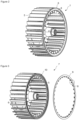
Figure 2 - is the perspective view of the fan and the support member related to another embodiment of the present invention, where the support member is attached on the fan. -
Figure 3 - is the view of the fan, the support member, the protrusion and the slot related to another embodiment of the present invention, before the support member is attached on the fan. -
Figure 4 - is the detailed view of the support member related to another embodiment of the present invention, showing the protrusion before the support member is attached on the fan. -
Figure 5 - is the detailed view of the support member related to another embodiment of the present invention, showing the protrusion engaging with the blade after the support member is attached on the fan. - The elements illustrated in the figures are numbered as follows:
- 1- Household appliance
- 2- Body
- 3- Drum
- 4- Hub
- 5- Blade
- 6- Frame
- 7- Fan
- 8- Protrusion
- 9- Support member
- 10- Slot
- 11- Curved section
- 12- Air duct
- The household appliance (1) comprises a body (2); a drum (3) which is disposed in the body (2) and wherein the laundry is loaded; an air duct (12) through which the drying air to be delivered to the drum (3) is circulated; and a fan (7) positioned in the air duct (12) and having a hub (4) which is suitable to be placed on a shaft rotated by a motor and a frame (6) having a plurality of blades (5) which move the air. The hub (4) is connected to the shaft rotated by the motor such that the fan (7) is rotated around its own axis. The frame (6) disposed on the fan (7) enables the blades (5) to be rotated together with the hub (4). Thus, the hub (4), the frame (6) and the blades (5) are rotated as a whole. The rotational movement of the blades (5) enables the drying air to be moved. Thus, the circulation of the drying air in the air duct (12) is ensured.
- The household appliance (1) of the present invention comprises at least one support member (9) which has a plurality of protrusions (8) thereon and which is placed on the fan (7) such that each protrusion (8) engages with one blade (5). The protrusions (8) provided on the support member (9) are placed on the blades (5) so as to ensure that the blades (5) are structurally supported by the support member (9). Thus, the area where the blades (5) join the frame (6) is strengthened and the blades (5) are prevented from breaking and deforming. Moreover, in the life tests carried out by the manufacturer, it is observed that the support member (9) effectively increases the economic life of the fan (7). In addition, in case of possible deformation of the blade (5), since the support member (9) is engaged with the blades (5), the blades (5) are prevented from breaking away from the frame (6) and suffering any damage casing the fan (7) to lose its function.
- In an embodiment of the present invention, at least one slot (10) is provided on the frame (6) and the support member (9) is fitted in the slot (10). The centripetal force on the blades (5) and the weight of the support member (9) are transmitted to the frame (6) by means of the slot (10). Thus, a solid connection is achieved between the support member (9) and the frame (6), and by connecting the support member (9) directly to the blades (5) by means of the slot (10), additional force is prevented from acting on the blades (5), thus preventing the blades (5) from breaking easily.
- In another embodiment of the present invention, the protrusion (8) has a U profile so as to at least partially surround the edge of each blade (5). The protrusion (8) has a U form which is suitable for receiving the blade (5) so as to grip the blade (5) from one edge. Since the blades (5) are generally in an angled or curved geometric form, the U shape of the protrusion (8) which surrounds at least a part of the blade (5) ensures that the blade (5) is structurally supported more effectively.
- In another embodiment of the present invention, the support member (9) is in the form of a ring so as to surround the frame (6). Thus, the support member (9) is enabled to grip the frame (6) better. Moreover, the forces transmitted from the blades (5) to the support member (9) and the own weight of the support member (9) are distributed to the larger surface area of the frame (6).
- In another embodiment of the present invention, two slots (10) are provided, each on one side of the frame (6) and two support members (9) are fitted in the slots (10). In this embodiment, a support member (9) is placed on each of the two sides of the frame (6) so as to be fitted into the slots (10). Thus, the strength and the noise dampening capability of the support member (9) are doubled.
- In another embodiment of the present invention, a plurality of curved sections (11) are provided on the protrusion (8). Thus, the durability of the areas on the protrusion (8) with the highest stress concentration is increased such that the protrusions (8) are prevented from breaking away from the support member (9) over time.
- In another embodiment of the present invention, the fan (7) and the support member (9) are manufactured in an integrated manner by the plastic injection method. The material to be used in plastic injection is manufactured from materials such as metal or high-strength plastic and rubber. The material predetermined by the manufacturer is melted and injected into the mold. The order in which the fan (7) or the support member (9) is injected into the mold may vary. When the fan (7) and the support member (9) are manufactured to be fully integrated with each other, a connection resistant to deformations is achieved.
- The household appliance (1) is a laundry dryer and/or a laundry washer/dryer.
- By means of the present invention, a household appliance (1) is realized, having a fan (7) with increased security of which the strength, the noise level and the economic life are improved in a cost-effective manner by means of the support member (9).
Claims (8)
- A household appliance (1) comprising a body (2); a drum (3) which is disposed in the body (2) and wherein the laundry is loaded; an air duct (12) through which the drying air to be delivered to the drum (3) is circulated; and a fan (7) positioned in the air duct (12) and having a hub (4) which is suitable to be placed on a shaft rotated by a motor and a frame (6) having a plurality of blades (5) which move the air, characterized by at least one support member (9) which has a plurality of protrusions (8) thereon and which is placed on the fan (7) such that each protrusion (8) engages with one blade (5).
- A household device (1) as in Claim 1, characterized by at least one slot (10) which is provided on the frame (6) and wherein the support member (9) is fitted.
- A household appliance (1) as in Claim 1 or Claim 2, characterized by the protrusion (8) which has a U profile so as to at least partially surround the edge of each blade (5).
- A household appliance (1) as in any one of the Claims 1 to 3, characterized by the support member (9) which is in the form of a ring so as to surround the frame (6).
- A household appliance (1) as in any one of the above claims, characterized by two slots (10) which are provided, each on one side of the frame (6) and by two support members (9) which are fitted in the slots (10).
- A household device (1) as in any one of the above claims, characterized by a plurality of curved sections (11) which are provided on the protrusion (8).
- A household appliance (1) as in any one of the above claims, characterized by the fan (7) and the support member (9) which are manufactured in an integrated manner by the plastic injection method.
- A household appliance (1) as in any one of the above claims, which is a laundry dryer and/or a laundry washer/dryer.
Applications Claiming Priority (1)
| Application Number | Priority Date | Filing Date | Title |
|---|---|---|---|
| TR202303038 | 2023-03-20 |
Publications (2)
| Publication Number | Publication Date |
|---|---|
| EP4435170A1 true EP4435170A1 (en) | 2024-09-25 |
| EP4435170B1 EP4435170B1 (en) | 2026-06-10 |
Family
ID=90123807
Family Applications (1)
| Application Number | Title | Priority Date | Filing Date |
|---|---|---|---|
| EP24160423.0A Active EP4435170B1 (en) | 2023-03-20 | 2024-02-29 | A household appliance |
Country Status (1)
| Country | Link |
|---|---|
| EP (1) | EP4435170B1 (en) |
Citations (4)
| Publication number | Priority date | Publication date | Assignee | Title |
|---|---|---|---|---|
| KR100469289B1 (en) * | 2003-01-28 | 2005-02-02 | 엘지전자 주식회사 | fan assembly and drying machine applying thereof and washing machine applying thereof |
| WO2007093274A1 (en) * | 2006-02-15 | 2007-08-23 | Electrolux Home Products Corporation N.V. | Domestic clothes drier with twin fan |
| WO2008000611A1 (en) * | 2006-06-29 | 2008-01-03 | BSH Bosch und Siemens Hausgeräte GmbH | Dryer with reduced noise generation, fan and impeller suitable therefor, and method for producing the impeller |
| EP2428682A2 (en) | 2010-09-14 | 2012-03-14 | General Electric Company | Bidirectional fan having self-adjusting vane |
-
2024
- 2024-02-29 EP EP24160423.0A patent/EP4435170B1/en active Active
Patent Citations (4)
| Publication number | Priority date | Publication date | Assignee | Title |
|---|---|---|---|---|
| KR100469289B1 (en) * | 2003-01-28 | 2005-02-02 | 엘지전자 주식회사 | fan assembly and drying machine applying thereof and washing machine applying thereof |
| WO2007093274A1 (en) * | 2006-02-15 | 2007-08-23 | Electrolux Home Products Corporation N.V. | Domestic clothes drier with twin fan |
| WO2008000611A1 (en) * | 2006-06-29 | 2008-01-03 | BSH Bosch und Siemens Hausgeräte GmbH | Dryer with reduced noise generation, fan and impeller suitable therefor, and method for producing the impeller |
| EP2428682A2 (en) | 2010-09-14 | 2012-03-14 | General Electric Company | Bidirectional fan having self-adjusting vane |
Also Published As
| Publication number | Publication date |
|---|---|
| EP4435170B1 (en) | 2026-06-10 |
Similar Documents
| Publication | Publication Date | Title |
|---|---|---|
| US4182598A (en) | Turbine blade damper | |
| US7270517B2 (en) | Turbine blade with vibration damper | |
| US20110127861A1 (en) | Motor of washing machine | |
| EP2949944B1 (en) | Centrifugal fan | |
| JP5613764B2 (en) | Impeller for turbomachinery | |
| JP2011190806A (en) | Impeller for centrifugal blower | |
| CN1453452A (en) | Compressor with multi-stage axial structure mode | |
| US7654797B2 (en) | Blade with shroud | |
| US2553078A (en) | Turbine blade mounting | |
| KR20190065911A (en) | Dual impeller | |
| JP5443601B2 (en) | Rotor blade for axial-flow turbomachine and assembly for such rotor blade | |
| CN1978870A (en) | Improved bladed stator for a turbo-engine | |
| CN112220367B (en) | Fan blade structure for cooking equipment and oven with structure | |
| CN220204186U (en) | Impeller and cooking utensil | |
| JPH01167402A (en) | Mechanically vibration-damped turbine impeller | |
| US3532439A (en) | Fibrous reinforced bladed rotor | |
| TR2023003038A2 (en) | A HOME APPLIANCE | |
| KR20250010739A (en) | dryer | |
| US20080166234A1 (en) | Blade and Fan Having the Same | |
| JPH11230094A (en) | Gas turbine engine | |
| EP2177658A1 (en) | Pulley and washing machine with a pulley | |
| KR20170088578A (en) | Axial Fan | |
| KR102758940B1 (en) | dryer | |
| KR100265648B1 (en) | Method for manufacturing blade impeller and blade impeller manufactured by such method | |
| KR101476189B1 (en) | Blowing fan |
Legal Events
| Date | Code | Title | Description |
|---|---|---|---|
| PUAI | Public reference made under article 153(3) epc to a published international application that has entered the european phase |
Free format text: ORIGINAL CODE: 0009012 |
|
| STAA | Information on the status of an ep patent application or granted ep patent |
Free format text: STATUS: REQUEST FOR EXAMINATION WAS MADE |
|
| 17P | Request for examination filed |
Effective date: 20240229 |
|
| AK | Designated contracting states |
Kind code of ref document: A1 Designated state(s): AL AT BE BG CH CY CZ DE DK EE ES FI FR GB GR HR HU IE IS IT LI LT LU LV MC ME MK MT NL NO PL PT RO RS SE SI SK SM TR |
|
| STAA | Information on the status of an ep patent application or granted ep patent |
Free format text: STATUS: EXAMINATION IS IN PROGRESS |
|
| 17Q | First examination report despatched |
Effective date: 20250612 |
|
| GRAP | Despatch of communication of intention to grant a patent |
Free format text: ORIGINAL CODE: EPIDOSNIGR1 |
|
| STAA | Information on the status of an ep patent application or granted ep patent |
Free format text: STATUS: GRANT OF PATENT IS INTENDED |
|
| INTG | Intention to grant announced |
Effective date: 20260401 |
|
| GRAS | Grant fee paid |
Free format text: ORIGINAL CODE: EPIDOSNIGR3 |
|
| GRAA | (expected) grant |
Free format text: ORIGINAL CODE: 0009210 |
|
| STAA | Information on the status of an ep patent application or granted ep patent |
Free format text: STATUS: THE PATENT HAS BEEN GRANTED |
|
| AK | Designated contracting states |
Kind code of ref document: B1 Designated state(s): AL AT BE BG CH CY CZ DE DK EE ES FI FR GB GR HR HU IE IS IT LI LT LU LV MC ME MK MT NL NO PL PT RO RS SE SI SK SM TR |
|
| REG | Reference to a national code |
Ref country code: CH Ref legal event code: F10 Free format text: ST27 STATUS EVENT CODE: U-0-0-F10-F00 (AS PROVIDED BY THE NATIONAL OFFICE) Effective date: 20260610 Ref country code: GB Ref legal event code: FG4D |
|
| REG | Reference to a national code |
Ref country code: DE Ref legal event code: R096 Ref document number: 602024005320 Country of ref document: DE |
|
| REG | Reference to a national code |
Ref country code: IE Ref legal event code: FG4D |