EP4435164A1 - Matelas isolant obtenu par une superposition de couches de fibres - Google Patents
Matelas isolant obtenu par une superposition de couches de fibres Download PDFInfo
- Publication number
- EP4435164A1 EP4435164A1 EP24165014.2A EP24165014A EP4435164A1 EP 4435164 A1 EP4435164 A1 EP 4435164A1 EP 24165014 A EP24165014 A EP 24165014A EP 4435164 A1 EP4435164 A1 EP 4435164A1
- Authority
- EP
- European Patent Office
- Prior art keywords
- layers
- insulating mattress
- insulating
- thickness
- superposition
- Prior art date
- Legal status (The legal status is an assumption and is not a legal conclusion. Google has not performed a legal analysis and makes no representation as to the accuracy of the status listed.)
- Pending
Links
Images



Classifications
-
- D—TEXTILES; PAPER
- D04—BRAIDING; LACE-MAKING; KNITTING; TRIMMINGS; NON-WOVEN FABRICS
- D04H—MAKING TEXTILE FABRICS, e.g. FROM FIBRES OR FILAMENTARY MATERIAL; FABRICS MADE BY SUCH PROCESSES OR APPARATUS, e.g. FELTS, NON-WOVEN FABRICS; COTTON-WOOL; WADDING ; NON-WOVEN FABRICS FROM STAPLE FIBRES, FILAMENTS OR YARNS, BONDED WITH AT LEAST ONE WEB-LIKE MATERIAL DURING THEIR CONSOLIDATION
- D04H1/00—Non-woven fabrics formed wholly or mainly of staple fibres or like relatively short fibres
- D04H1/40—Non-woven fabrics formed wholly or mainly of staple fibres or like relatively short fibres from fleeces or layers composed of fibres without existing or potential cohesive properties
- D04H1/42—Non-woven fabrics formed wholly or mainly of staple fibres or like relatively short fibres from fleeces or layers composed of fibres without existing or potential cohesive properties characterised by the use of certain kinds of fibres insofar as this use has no preponderant influence on the consolidation of the fleece
- D04H1/4209—Inorganic fibres
- D04H1/4218—Glass fibres
-
- B—PERFORMING OPERATIONS; TRANSPORTING
- B32—LAYERED PRODUCTS
- B32B—LAYERED PRODUCTS, i.e. PRODUCTS BUILT-UP OF STRATA OF FLAT OR NON-FLAT, e.g. CELLULAR OR HONEYCOMB, FORM
- B32B17/00—Layered products essentially comprising sheet glass, or glass, slag, or like fibres
- B32B17/02—Layered products essentially comprising sheet glass, or glass, slag, or like fibres in the form of fibres or filaments
-
- B—PERFORMING OPERATIONS; TRANSPORTING
- B32—LAYERED PRODUCTS
- B32B—LAYERED PRODUCTS, i.e. PRODUCTS BUILT-UP OF STRATA OF FLAT OR NON-FLAT, e.g. CELLULAR OR HONEYCOMB, FORM
- B32B17/00—Layered products essentially comprising sheet glass, or glass, slag, or like fibres
- B32B17/02—Layered products essentially comprising sheet glass, or glass, slag, or like fibres in the form of fibres or filaments
- B32B17/04—Layered products essentially comprising sheet glass, or glass, slag, or like fibres in the form of fibres or filaments bonded with or embedded in a plastic substance
-
- B—PERFORMING OPERATIONS; TRANSPORTING
- B32—LAYERED PRODUCTS
- B32B—LAYERED PRODUCTS, i.e. PRODUCTS BUILT-UP OF STRATA OF FLAT OR NON-FLAT, e.g. CELLULAR OR HONEYCOMB, FORM
- B32B3/00—Layered products comprising a layer with external or internal discontinuities or unevennesses, or a layer of non-planar shape; Layered products comprising a layer having particular features of form
- B32B3/02—Layered products comprising a layer with external or internal discontinuities or unevennesses, or a layer of non-planar shape; Layered products comprising a layer having particular features of form characterised by features of form at particular places, e.g. in edge regions
- B32B3/04—Layered products comprising a layer with external or internal discontinuities or unevennesses, or a layer of non-planar shape; Layered products comprising a layer having particular features of form characterised by features of form at particular places, e.g. in edge regions characterised by at least one layer folded at the edge, e.g. over another layer ; characterised by at least one layer enveloping or enclosing a material
-
- B—PERFORMING OPERATIONS; TRANSPORTING
- B32—LAYERED PRODUCTS
- B32B—LAYERED PRODUCTS, i.e. PRODUCTS BUILT-UP OF STRATA OF FLAT OR NON-FLAT, e.g. CELLULAR OR HONEYCOMB, FORM
- B32B5/00—Layered products characterised by the non- homogeneity or physical structure, i.e. comprising a fibrous, filamentary, particulate or foam layer; Layered products characterised by having a layer differing constitutionally or physically in different parts
- B32B5/22—Layered products characterised by the non- homogeneity or physical structure, i.e. comprising a fibrous, filamentary, particulate or foam layer; Layered products characterised by having a layer differing constitutionally or physically in different parts characterised by the presence of two or more layers which are next to each other and are fibrous, filamentary, formed of particles or foamed
- B32B5/24—Layered products characterised by the non- homogeneity or physical structure, i.e. comprising a fibrous, filamentary, particulate or foam layer; Layered products characterised by having a layer differing constitutionally or physically in different parts characterised by the presence of two or more layers which are next to each other and are fibrous, filamentary, formed of particles or foamed one layer being a fibrous or filamentary layer
- B32B5/26—Layered products characterised by the non- homogeneity or physical structure, i.e. comprising a fibrous, filamentary, particulate or foam layer; Layered products characterised by having a layer differing constitutionally or physically in different parts characterised by the presence of two or more layers which are next to each other and are fibrous, filamentary, formed of particles or foamed one layer being a fibrous or filamentary layer another layer next to it also being fibrous or filamentary
-
- B—PERFORMING OPERATIONS; TRANSPORTING
- B32—LAYERED PRODUCTS
- B32B—LAYERED PRODUCTS, i.e. PRODUCTS BUILT-UP OF STRATA OF FLAT OR NON-FLAT, e.g. CELLULAR OR HONEYCOMB, FORM
- B32B5/00—Layered products characterised by the non- homogeneity or physical structure, i.e. comprising a fibrous, filamentary, particulate or foam layer; Layered products characterised by having a layer differing constitutionally or physically in different parts
- B32B5/22—Layered products characterised by the non- homogeneity or physical structure, i.e. comprising a fibrous, filamentary, particulate or foam layer; Layered products characterised by having a layer differing constitutionally or physically in different parts characterised by the presence of two or more layers which are next to each other and are fibrous, filamentary, formed of particles or foamed
- B32B5/24—Layered products characterised by the non- homogeneity or physical structure, i.e. comprising a fibrous, filamentary, particulate or foam layer; Layered products characterised by having a layer differing constitutionally or physically in different parts characterised by the presence of two or more layers which are next to each other and are fibrous, filamentary, formed of particles or foamed one layer being a fibrous or filamentary layer
- B32B5/26—Layered products characterised by the non- homogeneity or physical structure, i.e. comprising a fibrous, filamentary, particulate or foam layer; Layered products characterised by having a layer differing constitutionally or physically in different parts characterised by the presence of two or more layers which are next to each other and are fibrous, filamentary, formed of particles or foamed one layer being a fibrous or filamentary layer another layer next to it also being fibrous or filamentary
- B32B5/265—Layered products characterised by the non- homogeneity or physical structure, i.e. comprising a fibrous, filamentary, particulate or foam layer; Layered products characterised by having a layer differing constitutionally or physically in different parts characterised by the presence of two or more layers which are next to each other and are fibrous, filamentary, formed of particles or foamed one layer being a fibrous or filamentary layer another layer next to it also being fibrous or filamentary characterised by one fibrous or filamentary layer being a non-woven fabric layer
- B32B5/266—Layered products characterised by the non- homogeneity or physical structure, i.e. comprising a fibrous, filamentary, particulate or foam layer; Layered products characterised by having a layer differing constitutionally or physically in different parts characterised by the presence of two or more layers which are next to each other and are fibrous, filamentary, formed of particles or foamed one layer being a fibrous or filamentary layer another layer next to it also being fibrous or filamentary characterised by one fibrous or filamentary layer being a non-woven fabric layer next to one or more non-woven fabric layers
-
- B—PERFORMING OPERATIONS; TRANSPORTING
- B32—LAYERED PRODUCTS
- B32B—LAYERED PRODUCTS, i.e. PRODUCTS BUILT-UP OF STRATA OF FLAT OR NON-FLAT, e.g. CELLULAR OR HONEYCOMB, FORM
- B32B7/00—Layered products characterised by the relation between layers; Layered products characterised by the relative orientation of features between layers, or by the relative values of a measurable parameter between layers, i.e. products comprising layers having different physical, chemical or physicochemical properties; Layered products characterised by the interconnection of layers
- B32B7/04—Interconnection of layers
- B32B7/05—Interconnection of layers the layers not being connected over the whole surface, e.g. discontinuous connection or patterned connection
-
- B—PERFORMING OPERATIONS; TRANSPORTING
- B32—LAYERED PRODUCTS
- B32B—LAYERED PRODUCTS, i.e. PRODUCTS BUILT-UP OF STRATA OF FLAT OR NON-FLAT, e.g. CELLULAR OR HONEYCOMB, FORM
- B32B7/00—Layered products characterised by the relation between layers; Layered products characterised by the relative orientation of features between layers, or by the relative values of a measurable parameter between layers, i.e. products comprising layers having different physical, chemical or physicochemical properties; Layered products characterised by the interconnection of layers
- B32B7/04—Interconnection of layers
- B32B7/12—Interconnection of layers using interposed adhesives or interposed materials with bonding properties
-
- D—TEXTILES; PAPER
- D04—BRAIDING; LACE-MAKING; KNITTING; TRIMMINGS; NON-WOVEN FABRICS
- D04H—MAKING TEXTILE FABRICS, e.g. FROM FIBRES OR FILAMENTARY MATERIAL; FABRICS MADE BY SUCH PROCESSES OR APPARATUS, e.g. FELTS, NON-WOVEN FABRICS; COTTON-WOOL; WADDING ; NON-WOVEN FABRICS FROM STAPLE FIBRES, FILAMENTS OR YARNS, BONDED WITH AT LEAST ONE WEB-LIKE MATERIAL DURING THEIR CONSOLIDATION
- D04H1/00—Non-woven fabrics formed wholly or mainly of staple fibres or like relatively short fibres
- D04H1/40—Non-woven fabrics formed wholly or mainly of staple fibres or like relatively short fibres from fleeces or layers composed of fibres without existing or potential cohesive properties
- D04H1/42—Non-woven fabrics formed wholly or mainly of staple fibres or like relatively short fibres from fleeces or layers composed of fibres without existing or potential cohesive properties characterised by the use of certain kinds of fibres insofar as this use has no preponderant influence on the consolidation of the fleece
- D04H1/4209—Inorganic fibres
-
- D—TEXTILES; PAPER
- D04—BRAIDING; LACE-MAKING; KNITTING; TRIMMINGS; NON-WOVEN FABRICS
- D04H—MAKING TEXTILE FABRICS, e.g. FROM FIBRES OR FILAMENTARY MATERIAL; FABRICS MADE BY SUCH PROCESSES OR APPARATUS, e.g. FELTS, NON-WOVEN FABRICS; COTTON-WOOL; WADDING ; NON-WOVEN FABRICS FROM STAPLE FIBRES, FILAMENTS OR YARNS, BONDED WITH AT LEAST ONE WEB-LIKE MATERIAL DURING THEIR CONSOLIDATION
- D04H1/00—Non-woven fabrics formed wholly or mainly of staple fibres or like relatively short fibres
- D04H1/40—Non-woven fabrics formed wholly or mainly of staple fibres or like relatively short fibres from fleeces or layers composed of fibres without existing or potential cohesive properties
- D04H1/58—Non-woven fabrics formed wholly or mainly of staple fibres or like relatively short fibres from fleeces or layers composed of fibres without existing or potential cohesive properties by applying, incorporating or activating chemical or thermoplastic bonding agents, e.g. adhesives
- D04H1/593—Non-woven fabrics formed wholly or mainly of staple fibres or like relatively short fibres from fleeces or layers composed of fibres without existing or potential cohesive properties by applying, incorporating or activating chemical or thermoplastic bonding agents, e.g. adhesives to layered webs
-
- D—TEXTILES; PAPER
- D04—BRAIDING; LACE-MAKING; KNITTING; TRIMMINGS; NON-WOVEN FABRICS
- D04H—MAKING TEXTILE FABRICS, e.g. FROM FIBRES OR FILAMENTARY MATERIAL; FABRICS MADE BY SUCH PROCESSES OR APPARATUS, e.g. FELTS, NON-WOVEN FABRICS; COTTON-WOOL; WADDING ; NON-WOVEN FABRICS FROM STAPLE FIBRES, FILAMENTS OR YARNS, BONDED WITH AT LEAST ONE WEB-LIKE MATERIAL DURING THEIR CONSOLIDATION
- D04H13/00—Other non-woven fabrics
-
- B—PERFORMING OPERATIONS; TRANSPORTING
- B32—LAYERED PRODUCTS
- B32B—LAYERED PRODUCTS, i.e. PRODUCTS BUILT-UP OF STRATA OF FLAT OR NON-FLAT, e.g. CELLULAR OR HONEYCOMB, FORM
- B32B2250/00—Layers arrangement
- B32B2250/05—5 or more layers
-
- B—PERFORMING OPERATIONS; TRANSPORTING
- B32—LAYERED PRODUCTS
- B32B—LAYERED PRODUCTS, i.e. PRODUCTS BUILT-UP OF STRATA OF FLAT OR NON-FLAT, e.g. CELLULAR OR HONEYCOMB, FORM
- B32B2250/00—Layers arrangement
- B32B2250/20—All layers being fibrous or filamentary
-
- B—PERFORMING OPERATIONS; TRANSPORTING
- B32—LAYERED PRODUCTS
- B32B—LAYERED PRODUCTS, i.e. PRODUCTS BUILT-UP OF STRATA OF FLAT OR NON-FLAT, e.g. CELLULAR OR HONEYCOMB, FORM
- B32B2262/00—Composition or structural features of fibres which form a fibrous or filamentary layer or are present as additives
- B32B2262/06—Vegetal fibres
-
- B—PERFORMING OPERATIONS; TRANSPORTING
- B32—LAYERED PRODUCTS
- B32B—LAYERED PRODUCTS, i.e. PRODUCTS BUILT-UP OF STRATA OF FLAT OR NON-FLAT, e.g. CELLULAR OR HONEYCOMB, FORM
- B32B2262/00—Composition or structural features of fibres which form a fibrous or filamentary layer or are present as additives
- B32B2262/06—Vegetal fibres
- B32B2262/062—Cellulose fibres, e.g. cotton
- B32B2262/067—Wood fibres
-
- B—PERFORMING OPERATIONS; TRANSPORTING
- B32—LAYERED PRODUCTS
- B32B—LAYERED PRODUCTS, i.e. PRODUCTS BUILT-UP OF STRATA OF FLAT OR NON-FLAT, e.g. CELLULAR OR HONEYCOMB, FORM
- B32B2262/00—Composition or structural features of fibres which form a fibrous or filamentary layer or are present as additives
- B32B2262/10—Inorganic fibres
- B32B2262/101—Glass fibres
-
- B—PERFORMING OPERATIONS; TRANSPORTING
- B32—LAYERED PRODUCTS
- B32B—LAYERED PRODUCTS, i.e. PRODUCTS BUILT-UP OF STRATA OF FLAT OR NON-FLAT, e.g. CELLULAR OR HONEYCOMB, FORM
- B32B2262/00—Composition or structural features of fibres which form a fibrous or filamentary layer or are present as additives
- B32B2262/12—Conjugate fibres, e.g. core/sheath or side-by-side
-
- B—PERFORMING OPERATIONS; TRANSPORTING
- B32—LAYERED PRODUCTS
- B32B—LAYERED PRODUCTS, i.e. PRODUCTS BUILT-UP OF STRATA OF FLAT OR NON-FLAT, e.g. CELLULAR OR HONEYCOMB, FORM
- B32B2307/00—Properties of the layers or laminate
- B32B2307/10—Properties of the layers or laminate having particular acoustical properties
- B32B2307/102—Insulating
-
- B—PERFORMING OPERATIONS; TRANSPORTING
- B32—LAYERED PRODUCTS
- B32B—LAYERED PRODUCTS, i.e. PRODUCTS BUILT-UP OF STRATA OF FLAT OR NON-FLAT, e.g. CELLULAR OR HONEYCOMB, FORM
- B32B2307/00—Properties of the layers or laminate
- B32B2307/30—Properties of the layers or laminate having particular thermal properties
- B32B2307/304—Insulating
Definitions
- the present invention relates to the field of construction materials, and more particularly to the field of construction materials formed from an insulating mattress, formed for example from glass fibers or plant fibers. Such construction materials are notably used to provide thermal and/or acoustic insulation.
- Insulating blankets made of mineral or plant fibres are commonly used as insulation materials intended to provide thermal and/or acoustic insulation, for example during the construction of buildings.
- the insulating properties of these insulating blankets are obtained, in particular, by the ability of said blankets to trap air in a stable and immobile manner within them.
- Insulating mattresses are obtained by passing a carpet of mineral or plant fibres through an oven, formed on a conveyor device upstream of the oven.
- This carpet of fibres is formed, for example, from a mixture of glass fibres, virgin or recycled, or wood fibres entangled with each other, and binding elements intended to bind the fibres together during passage through the oven.
- the present invention falls within this context and aims to optimize the insulating properties of an insulating blanket comprising mineral and/or plant fibers.
- This optimization is obtained by increasing the quantity of air trapped in a stable manner in the insulating blanket, by ensuring a stratified distribution of the fibers and by limiting the presence of fibers oriented in a secant manner to the elongation plane of the blanket. Indeed, such an orientation contributes to generating thermal bridges in the thickness of the blanket which contribute to the propagation of heat by thermal conduction within the fiber blanket.
- the present invention relates to an insulating mattress formed from a superposition of layers formed from a plurality of fibers bonded to each other by means of a binding element, the insulating mattress being formed from a superposition of at least 30 layers.
- the superposition of layers makes it possible to immobilize air in a stable manner between two layers. Such a superposition of layers thus makes it possible to improve the insulating properties of an insulating blanket formed by this superposition of layers by limiting the formation of thermal bridges between two adjacent layers.
- This limitation of the formation of thermal bridges within the insulating blanket is achieved by orienting the fibers in a laminar manner in an elongation plane of said insulating blanket. In other words, each fiber extends in a single extension plane and the insulating blanket is formed by a superposition of extension planes parallel to each other. It is understood that the greater the number of layers, the better the insulating properties of the insulating blanket.
- the insulating mattress has a specific weight and a given thickness, these characteristics making it possible to obtain, for the finished product, acoustic or thermal insulation performances corresponding to what is expected by the user.
- a layer having a grammage allowing at least 30 layers to be superimposed is chosen.
- the number of layers is chosen so that the grammage of the insulating blanket is precisely achieved, with this constraint of having at least 30 layers.
- the grammage of the insulating blanket is equal to the average grammage of a layer multiplied by the number of layers of the insulating blanket.
- the average grammage of a layer is 10g.m -2
- the grammage of thirty layers before and after baking the superposition of layers to form the insulating blanket will be substantially equal to 300g.m -2 .
- the choice of the number of layers is also considered according to the thickness to be respected of the insulating blanket.
- the thickness of the insulating blanket is equal to the sum of the average thickness of a layer and the thickness of an air layer between two adjacent layers, multiplied by the number of layers of the insulating blanket, and it is ensured that the average thickness of a layer multiplied by the number of layers during the manufacturing process of the insulating blanket is at least equal to, if necessary greater than, the thickness to be respected of the insulating blanket.
- the number of layers chosen to make up the mattress must be greater than 30 layers, to optimize the insulating performance, and this number must make it possible to achieve the exact weight of the insulating mattress as soon as all the layers are superimposed on each other during the manufacturing process of the insulating mattress, while making it possible to achieve or exceed the thickness to be respected for the insulating mattress when all the layers are superimposed on each other during the manufacturing process of the insulating mattress.
- the number of layers is chosen to arrive exactly at the grammage of the insulating blanket and to arrive at least at the thickness to be respected of this insulating blanket, with a number of layers at least greater than the threshold value determined by the inventors.
- the threshold value is defined to have the best possible insulation, by multiplying the air layers between flat layers within which the fibers are arranged flat, without overlapping each other and therefore without risk that a fiber protruding from the layer will create a thermal bridge with an adjacent layer through an air layer.
- the threshold value is equal to 30 layers.
- the inventors were able to demonstrate that the threshold value of 30 layers was a good compromise between a low-weight layer allowing a large number of layers to be superimposed for a given insulating blanket, i.e. for an insulating blanket with a defined weight to be obtained at the end of the process, and industrial reality.
- Layers having a weight of the order of 10g.m -2 , 15g.m -2 , 25g.m -2 or even 30g.m -2 can allow the implementation of the invention to obtain a wide range of insulating blankets, between 400g.m -2 and 4kg.m -2 for example, while respecting this threshold value of 30 layers to be superimposed.
- the insulating properties of the insulating blanket are then optimal, in particular by the number of superimposed layers and the quantity of air thus immobilized in a stable manner within the blanket, between each of the adjacent layers of said superposition of at least 30 layers. Furthermore, the low grammage of the layers allows a distribution of the fibers within the layer which avoids the overlapping of the fibers within this layer, which allows the reduction of the number of thermal bridges likely to join two adjacent layers and thus improve insulation performance.
- the fibers bonded to each other by means of a binding element are mineral and/or plant fibers. This distinguishes it from insulating mattresses mainly comprising synthetic fibers. More particularly, the fibers are of the glass wool or rock wool type.
- the insulating blanket is formed of a superposition of at least 50 layers. This number can in particular be achieved by producing low-grammage layers.
- a number of superimposed layers can be provided, in order to obtain the grammage to be respected of the insulating blanket, which is greater than that in the insulating blankets of the prior art. For example, for a grammage value of the insulating blanket of 1 kg.m -2 , the number of superimposed layers is 50 layers if the average grammage of a layer is of the order of 20 g.m -2 and 100 layers if the average grammage of a layer is of the order of 10 g.m -2 .
- the average weight of a layer is such that the number of layers of the insulating mattress multiplied by this average weight is equal to the weight to be respected of the insulating mattress, the thickness resulting from the superposition of layers being equal to or greater than the thickness to be respected of the insulating mattress.
- each layer of the insulating blanket has a grammage of between 8 gm -2 and 30 gm -2 .
- the grammage of the insulating blanket is according to the invention obtained by considering the grammage of each superimposed layer, and more particularly by considering the average grammage of the layers and by multiplying this average grammage by the number of superimposed layers.
- Such a grammage of the layers forming the insulating blanket allows, for a given grammage of the insulating blanket, to superimpose a large number of layers.
- the inventors were able to observe that with such an average grammage of the layers, it is possible to obtain the grammage of a large number of insulating mattresses marketed on the market, with optimized insulation performance due to the large number of superimposed layers.
- This large number of layers may imply an excess thickness of the superposition of layers compared to the thickness to be respected of the insulating mattress, but this thickness of the superposition of layers can easily be brought back to the height of the thickness to be respected of the mattress by pressing means.
- each layer has a thickness of between 0.05 mm and 2 mm.
- This low thickness of the layers forming the insulating mattress is linked to the low grammage of these, comprised according to the invention between 8 gm -2 and 30 gm -2 .
- few fibers and binding element are provided so that these components have little risk of overlapping, which makes it possible to contain the thickness of the layer.
- the number of layers to be superimposed is chosen according to the weight of the layers available to identically achieve the weight to be respected of the insulating mattress.
- the number of layers, at least greater than 30, is chosen so that it is as high as possible with layers however having a weight at least equal to 8 gm -2 , to ensure their mechanical strength when the layers are superimposed.
- it is ensured that the thickness of the superposition is greater than the thickness to be respected of the insulating mattress, and the thickness of the mattress is adjusted by pressing means, before, during or after a passage in an oven of the superposition of layers to obtain the insulating mattress.
- each layer has a thickness of between 0.1 mm and 1 mm.
- the binding element is formed of thermally bonding elements.
- the thermally bonding elements make it possible to provide each of the layers forming the insulating mattress with mechanical resistance limiting the risk of the layers disintegrating, in particular due to the thin thickness of the latter.
- the insulating blanket comprises between 2% and 30% of thermally bonding elements.
- the thermally bonding elements present within the insulating blanket represent a mass of between 2% and 30% of the total mass of the insulating blanket.
- the insulating blanket comprises less than 15% of thermally bonding elements.
- the thermally bonding elements present in the insulating blanket represent a mass of less than 15% of the total mass of the insulating blanket.
- such a content of thermally bonding elements, less than 15% limits the use of plastic material in the insulating blanket, which presents an advantage in terms of cost and respect for the environment.
- each layer of the insulating blanket comprises a content of less than 15% of thermally bonding elements. This is again a mass percentage, such that the mass of thermally bonding elements present in a layer is less than 15% of the total mass of said layer considered.
- Such a feature makes it possible to form an insulating blanket whose mass of thermally bonding elements is, according to the invention, less than 15% while guaranteeing a certain homogeneity between each layer.
- the insulating mattress comprises between 3% and 15% of thermal bonding elements.
- the insulating blanket comprises between 4% and 10% of thermally bonding elements.
- the content of binding element is between 4% and 10%
- the thermally bonding elements present within the insulating blanket representing a mass of between 4% and 10% of the mass of the insulating blanket.
- each layer of the insulating blanket advantageously has a content of thermally bonding elements which is substantially equal to the content of the other layers of the insulating blanket, to ensure a homogeneous distribution of the thermally bonding elements over the entire thickness of the insulating blanket.
- thermal binding elements of between 4% and 10% makes it possible to provide each layer, in particular due to their low thickness, with mechanical strength that prevents them from disintegrating. It should be noted that by “disintegrating” is meant that the layer crumbles and the fibers dissociate from each other within said layer.
- the insulating mattress has a volume density of between 5kg.m -3 and 200kg.m -3 .
- the insulating mattress has a volume density of between 5kg.m -3 and 40kg.m -3 .
- the fibers have a maximum length of 20 mm.
- each superimposed layer is inclined relative to a plane perpendicular to a direction in which the thickness of the insulating blanket is measured by an orientation angle of less than 10°.
- each superimposed layer is inclined relative to a plane perpendicular to a direction in which the thickness of the insulating blanket is measured by an orientation angle of between 4° and 8°.
- the plane used as a reference to define the inclination of each layer is parallel to the surface of the conveyor on which the insulating mattress rests during of its manufacture. It is understood that the orientation angle previously mentioned can be measured during the manufacturing process, between the conveyor on which the superposition of layers circulates and the extension plane in which the layer considered is inscribed.
- Such a manufacturing method makes it possible to automate the manufacture of insulating mattresses by combining the production of layers, the thickness of which is between 0.05 mm and 2 mm, from a primary web obtained by the air forming device and the superposition of the latter on top of each other. It is understood that each layer of an insulating mattress is formed from the same primary web, the layers being superimposed on top of each other to form a primary sheet which, once heated in an oven, forms the insulating mattress.
- the first step is preceded by a step of selecting the grammage of the primary web, said grammage of the primary web multiplied by the number of layers to be superimposed, at least equal to 30, having to be equal to the grammage to be respected of the insulating blanket and the corresponding thickness of the primary web multiplied by this number of layers having to be at least equal to the thickness to be respected of the insulating blanket.
- weight of the primary veil thus selected corresponds to the average weight of a layer of the superposition of layers.
- operating parameters of the air forming device are defined, following the step of selecting the grammage of the primary web, to obtain during the first step the selected grammage of the primary web.
- one of said operating parameters is the running speed of the first conveyor.
- the primary web is deposited on a support web present on the first conveyor.
- This support web makes it possible, for example, to transport the primary web from the air forming device to the lapping device when the first conveyor and the second conveyor are discontinuous. Indeed, due to the small thickness of the primary web, removing the primary web from the first conveyor by directly gripping the primary web could damage the primary web.
- the manufacturing method implements a step prior to the second step during which the primary web is heated by a heating device.
- This heating of the primary web allows the thermal bonding elements present in the primary web to bond the fibers to each other.
- the primary web has improved mechanical strength and can be handled or stored without risk of the latter disintegrating.
- the manufacturing method can implement a step of adjusting the thickness of the superposition of layers, before, during or after the third step, to provide an insulating mattress with a given thickness.
- This adjustment of the thickness implements pressing means, for example by rollers arranged on the path of the superposition of layers, which tend to reduce the thickness of the superposition of layers to bring the insulating mattress to the thickness to be respected.
- the insulating blanket which is the subject of the invention and a superposition of layers which makes it possible to obtain this insulating blanket insofar as the insulating blanket is obtained by passing said superposition of layers through an oven.
- said superposition of layers Prior to passing through the oven, said superposition of layers is formed by depositing layers of fibers formed by a primary veil on top of each other and it is the cooking in the oven of this assembly, and where appropriate a subsequent compression step before conditioning, which forms the insulating blanket.
- FIG 1 schematically illustrates a sectional view of an insulating mattress 2 according to an embodiment of the invention.
- This insulating mattress 2 is formed, in accordance with the present invention, from a superposition of layers 4 themselves formed from a plurality of fibers bonded to each other by means of a binding element.
- the fibers which will be described in more detail in connection with the figure 3 , are in the embodiment shown glass fibers obtained by the transformation, for example, of raw materials or by the recycling of glass fibers, for example from a glass wool mattress.
- the fibers used to form the layers forming the insulating mattress 2 may be plant fibers, for example obtained by the defibering of Douglas fir wood.
- the insulating mattress 2 represented by the figure 1 extends in a longitudinal main elongation direction, parallel to the axis L.
- This insulating blanket 2 has a rectangular shape at the oven outlet, the length of which, which forms the largest dimension of the insulating blanket 2, is measured parallel to said longitudinal main elongation direction.
- the width of the insulating blanket 2, which forms the second dimension of the insulating blanket 2 in terms of size, is measured in a transverse direction perpendicular to the longitudinal main elongation direction.
- the thickness of the insulating blanket 2 is the smallest dimension of said insulating blanket 2 compared to the length and the width. This thickness is perpendicular to the length and the width of the insulating blanket 2, i.e. perpendicular to the longitudinal main elongation direction and to the transverse direction. In addition, the thickness is measured in a vertical direction, parallel to the axis V.
- the layers 4 are superimposed on each other in a stacking direction.
- This superposition of layers 4 is, according to the invention, at least 30 layers, preferably at least 50 layers, even more preferably at least 70 layers.
- the stacking direction is perpendicular to the plane of elongation of the different layers 4. In the embodiment represented by the figure 1 , this stacking direction is parallel to the vertical direction corresponding to the direction along which the thickness of the insulating blanket 2 is measured.
- the thickness of the layers 4 is between 0.05 mm and 2 mm, preferably between 0.1 mm and 1 mm, and this thickness is notably due to the low grammage of the primary veil participating in forming each of the layers, as will be presented below.
- the average grammage of a layer is between 8 gm -2 and 35 gm -2 , and it can in particular be equal to 10 gm -2 (points G1 on the figure 4 ), 15 gm -2 (points G2 on the figure 4 ), 25 gm -2 (points G3 on the figure 4 ) or 30 gm -2 (points G4 on the figure 4 ).
- the thickness of a layer is of the order of 1 mm.
- the layers 4 come from a mattress of fibers forming a primary web whose thickness is between 0.05 mm and 2 mm, preferably between 0.1 mm and 1 mm and this low-grammage primary web can in particular be obtained by an air forming device which will be described in more detail in connection with the figure 4 .
- each layer i.e. the primary veil
- the specificities of each layer are defined in such a way as to maximize the number of layers 4 that can be superimposed on each other, while respecting the desired thickness and weight of the insulating mattress.
- the thickness of the layers 4 is measured along the stacking direction of said layers 4. In the embodiment represented by the figure 1 , the thickness of each layer 4 is measured parallel to the thickness of the insulating mattress 2.
- each of the layers 4 extends in a plane perpendicular to the stacking direction of the layers 4 within the insulating blanket.
- the primary veil is cut to the desired dimensions to obtain the layers 4, this cutting of the primary veil being advantageously carried out repetitively so that each layer 4 has dimensions similar to the other layers 4. It should be noted that the cutting of the primary web mentioned in connection with this embodiment is carried out perpendicular to the direction of advancement of the conveyor such that each cut layer 4 has similar dimensions in the longitudinal direction. It is understood that such cutting makes it possible to limit the longitudinal waste of the insulating mattress 2.
- the primary web cut into layers 4 is transported to an assembly area.
- This transport of the layers 4 is, here, carried out manually.
- the primary web is transported on a rigid support web, making it possible not to damage the primary web during its transport.
- the primary web thus transported and cut to the desired dimensions is deposited in successive layers, the support web used for transport being removed prior to deposition, and the superposition of layers is directed to an oven to form an insulating mattress in accordance with the invention.
- the layers 4 are, in this embodiment shown, distinct from one another. Such a distinction of the superimposed layers 4 makes it possible to deposit them one on top of the other with a stacking direction which is perpendicular to the elongation plane of each of the layers forming the insulating blanket 2. Such an arrangement of the layers 4 makes it possible to immobilize air in strata parallel to the main elongation plane of the insulating blanket, which is optimal for improving the insulating properties of the product obtained.
- FIG 2 schematically represents a local sectional view of the insulating mattress 2 according to another embodiment. It should be noted that the sectional plane making visible the interior of the insulating mattress 2 visible on the figure 2 , is parallel to the cutting plane making visible the interior of the insulating mattress 2 visible on the figure 1 . It should also be noted that on the figure 2 the magnification is greater than that of the figure 1 to enable the inclination of the layers 4 within the insulating mattress 2 to be highlighted in this embodiment. Like the insulating mattress 2 represented by the figure 1 , the insulating mattress 2 represented by the figure 2 comprises, according to the invention, at least 30 layers 4.
- the primary veil is not cut and it is deposited in several successive layers, each layer 4 being formed in one piece with the other layers 4.
- the layers 4 have an inclination relative to a main elongation plane of the insulating blanket 2.
- This main elongation plane 6 extends longitudinally and transversely, that is to say according to the two largest dimensions of the insulating blanket 2. As a reminder, these two dimensions are the length and the width of the insulating blanket 2 at the outlet of the oven. Indeed, as visible on the figure 2 , the stacking direction of the layers 4 is secant with respect to the direction along which the thickness of the insulating blanket 2 is measured.
- each layer 4 forming the insulating mattress 2 is, in this embodiment shown, formed in the continuity of the adjacent layers 4.
- the primary veil is deposited on a rolling support 7 circulating at constant speed.
- the deposition of the primary veil is carried out by superimposing a first end of the layer being deposited on the previously deposited layers and a second end of this layer being deposited, opposite the first end, directly in contact with the rolling support 7.
- Such deposition generates an offset between the first end and the second end relative to a direction perpendicular to a plane in which the rolling support 7 extends, which generates an inclination of the layer being deposited relative to said plane of the rolling support 7.
- the inclination of the layers 4 generates an orientation angle ⁇ defined between a layer 4 and a plane parallel to the plane of the conveyor belt, perpendicular to the direction in which the thickness of the insulating blanket 2 is measured.
- This direction in which the thickness of the insulating blanket is measured is perpendicular to the plane of the conveyor belt 7.
- This orientation angle ⁇ is less than 10°, preferably between 4° and 8°.
- the low thickness of the layers 4, in accordance with the invention, makes it possible to limit the offset between the first end and the second end of each layer 4 relative to said direction perpendicular to the plane of the conveyor belt 7 and therefore to limit the value of the orientation angle ⁇ of the layers 4. It is understood that the smaller the offset between the first and second ends relative to the direction in which the thickness of the insulating blanket 2 is measured, the smaller the orientation angle ⁇ .
- a superposition of layers such as those mentioned above, i.e. whose grammage is between 8 gm -2 and 30 gm -2 and/or whose thickness is between 0.05 mm and 2 mm, makes it possible to ensure that the orientation angle ⁇ is as small as possible.
- the inventors were able to observe that having the lowest possible orientation angle ⁇ of the layers made it possible to increase the thermal resistance of the insulating blanket 2 by limiting the formation of thermal bridges in the thickness of the insulating blanket 2.
- layers 4 are, in the embodiment represented by the figure 2 , deposited on top of each other so that each layer 4 of the insulating mattress 2 is substantially parallel to the other layers 4. It is understood from the above that each layer 4 extends, in this embodiment, with the same orientation angle ⁇ relative to the plane of the conveyor belt 7.
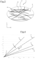
- FIG 3 schematically represents a detailed view of a layer 4 forming the insulating blanket 2.
- This detailed view makes it possible in particular to visualize fibers 8 forming, as mentioned previously, each of the layers 4 of the insulating blanket 2. It should be noted that this detailed view of a layer 4 is obtained after passing the superposition of layers 4 through an oven to obtain the insulating blanket.
- this detailed view of a layer 4 illustrates the fibers 8 joined together by a dry process, that is to say with dry binder elements.
- dry binder elements 10 as a means of joining the fibers 8 together helps to ensure the homogeneity of the fibers 8 within the layer 4 compared to a liquid binder element. Indeed, this dry process does not form agglomerates of fibers 8, as can be the case when several fibers are trapped in a liquid binder, which makes it possible to obtain layers 4 whose thickness is between 0.05 mm and 2 mm.
- the binding elements 10 are thermal binding elements. These binding elements 10 are mixed with the fibers 8 such that the mixture of binding elements 10 and fibers 8 comprises a content of binding elements 10 of between 2% and 30%, preferably between 3% and 15%, more preferably between 4% and 10%. It is understood that the primary web, obtained by this mixture, and each layer 4 resulting from the primary web also comprise a content of binding elements 10 of between 2% and 30%, preferably between 3% and 15%, more preferably between 4% and 10%.
- This percentage of binding elements 10 in the mixture as well as in each layer 4 represents the mass percentage of binding elements 10 relative to the mass of the mixture or relative to the mass of each layer 4.
- a layer 4 whose mass is 20 grams has a mass of binding elements 10 between 0.4 grams and 6 grams.
- the binding elements 10 are formed, in the embodiment shown, of a core 12 and a sheath 14.
- the core 12 forms a rigid part of the binding elements 10 providing the layer 4 with mechanical strength, while the sheath 14 ensures the joining of the fibers 8 to each other.
- the core 12 and the sheath 14 have different melting temperatures, and more precisely the sheath 14 has a lower melting temperature than the core 12.
- the sheath 14 when passing the superposition of layers 4 through an oven to obtain an insulating mattress 2 according to the invention, the sheath 14 is brought to a temperature which generates its fusion, which has the effect of bathing together the adjacent fibers 8 and the core of each of the thermally bonding elements, the material of the sheath then being intended to resolidify by cooling at the outlet of the oven so as to secure these fibers 8 with each other.
- the melting temperature of the core 12 is provided so that, despite the passage through the oven of the superposition of layers consisting of the mixture of fibers 8 and binding elements 10, the core 12 retains its rigid property participating in ensuring mechanical resistance to the insulating mattress 2 after its passage through the oven.
- an insulating blanket according to the invention is particular in that it comprises a minimum number of superimposed layers which is high compared to that of the prior art.
- the average grammage and the average thickness of a layer of this superposition of layers is chosen so that the number of layers is at least greater than 30. It being understood that obtaining a layer with a low grammage is difficult to implement and involves layers with low mechanical strength, it may be desirable to choose an average grammage of the layers as high as possible, provided that the minimum number of layers of 30 is respected and that the thickness of the insulating blanket which results from the superposition of layers is at least respected. Examples of selection of the grammage of the primary veil, that is to say the average grammage of a layer of the superposition of layers, are given with reference to the figure 4 .
- FIG 4 is a diagram in which three different finished products are identified, P1, P2, P3, the diagram making it possible to identify the weight and thickness to be respected for these insulating mattresses.
- the first insulating mattress P1 must have at the end of the manufacturing process a thickness of 220mm and a weight of 2300g.m -2
- the second insulating mattress P2 must have at the end of the manufacturing process a thickness of 180mm and a weight of 3000g.m -2
- the third insulating mattress P3 must have at the end of the manufacturing process a thickness of 20mm and a weight of 300g.m -2 .
- the goal is to arrive exactly at the grammage and to arrive at least at the thickness, with a number of layers at least greater than the threshold value determined by the inventors and with the layers that have the highest possible grammage for mechanical resistance.
- the threshold value is defined to have the best possible insulation, by multiplying the air layers between substantially flat layers.
- the threshold value is equal to 30 layers.
- the user has the possibility of having a first primary veil of 10 gm -2 (line C1 on the figure 4 ), a second primary veil of 15 gm -2 (line C2 on the figure 4 ), a third primary veil of 25 gm -2 (line C3 on the figure 4 ) or even a fourth primary veil of 30 gm -2 (line C4 on the figure 4 ).
- a first primary veil of 10 gm -2 line C1 on the figure 4
- a second primary veil of 15 gm -2 line C2 on the figure 4
- a third primary veil of 25 gm -2 line C3 on the figure 4
- a fourth primary veil of 30 gm -2 line C4 on the figure 4
- the user To obtain the first insulating blanket P1, the user considers the grammage of 2300g.m -2 and deduces that he will reach this total grammage with 230 layers of the first primary veil, which generates a layer superposition of 230mm, or with approximately 153 layers of the second primary veil, which generates a layer superposition of 153mm, or with 92 layers of the third primary veil, which generates a layer superposition of 92mm, or with approximately 77 layers of the fourth primary veil which generates a layer superposition of 77mm.
- the user considers the grammage of 300g.m -2 and deduces that he will reach this total grammage with 30 layers of the first primary veil, which generates a layer superposition of 30mm, or with 20 layers of the second primary veil, which generates a layer superposition of 20mm, or with 12 layers of the third primary veil, which generates a layer superposition of 12mm, or with 10 layers of the fourth primary veil which generates a layer superposition of 10mm.
- the user considers the grammage of 3000g.m -2 and deduces that he will reach this total grammage with 300 layers of the first primary veil, which generates a layer superposition of 300mm, or with 200 layers of the second primary veil, which generates a layer superposition of 200mm, or with 120 layers of the third primary veil, which generates a layer superposition of 120mm, or with 100 layers of the fourth primary veil which generates a layer superposition of 100mm.
- the user can choose the first primary veil as well as the second primary veil since a superposition of layers from the first primary veil or the second primary veil makes it possible to achieve the required thickness of 180 mm of the insulating mattress.
- the process of selecting the weight of the primary web involves choosing the second primary web rather than the first primary web, to choose the primary web of higher weight to favor the primary web of greater mechanical strength.
- the invention includes, where appropriate, a step of selecting the grammage of the primary web, in an overall method of obtaining an insulating blanket, during which the grammage of the primary web multiplied by the number of layers to be superimposed, at least equal to 30, must be equal to the grammage to be respected of the insulating blanket and the corresponding thickness of the primary web multiplied by this number of layers must be at least equal to the thickness to be respected of the insulating blanket.
- FIG. 5 represents an air forming device 16 for producing a primary web 18 used to subsequently form the different layers 4 of the insulating mattress 2, in particular in the context of a low-weight layer chosen where appropriate during a weight selection step as mentioned above.
- the air forming device 16 is capable of implementing a method of forming a primary web 18, better known under the English name of “Airlaid” process.
- the primary web 18 can be cut to the desired dimensions so that each cut forms a layer 4 distinct from the others and capable of being superimposed on other layers, or it can be kept in one piece and arranged in successive layers 4 by a lay-up device, which will be described in more detail in connection with the figure 6 .
- the air forming device 16 comprises a first feed channel 20 through which the binding elements 10 are introduced into the air forming device 16, and a second feed channel 22 through which the fibers 8 are introduced into the air forming device 16.
- the binder elements 10 are introduced in a disorderly manner into the first feed channel 20 and the fibers are introduced in a disorderly manner into the second feed channel 22.
- the fibers 8 may come from a set of recycled fibers, packaged in the form of a roll or a bale, and previously defibrated in a defibration installation, so that the fibers introduced into the air forming device 16 are separated from each other.
- the fibers 8 and the binding elements 10 are mixed together in a conduit 24 so that, in accordance with the invention, the content of binding element 10 in the primary veil 18 and more broadly in the insulating blanket 2 is between 2% and 30%, preferably between 3% and 15%, more preferably between 4% and 10%.
- the introduction of the binding elements 10 and the fibers 8 is controlled by the air forming device 16. It is understood that the quantity of fibers 8 introduced into the conduit 24 and the quantity of binding elements 10 introduced into the conduit 24 are controlled by the air forming device 16 so that the mixture of fibers 8 and binding elements 10 in the conduit 24 has a content of binding elements 10, according to the invention, of between 2% and 30%, preferably of between 3% and 15%, more preferably of between 4% and 10%.
- the air forming device 16 is configured so that over a given time interval, 2% to 30% of the mass introduced into the conduit 24 is formed of binding elements 10, the remaining introduced mass being formed of the fibers 8. It is understood that the percentage expressed is a mass percentage which illustrates the ratio between the observed weight of the binding elements and the total weight of the assembly formed by the binding elements and the fibers.
- the introduction of the fibers 8 and the binding elements 10 into the air forming device 16 is carried out by means of an air flow sucking up the fibers 8 and the binding elements 10. This air flow also makes it possible to ensure the mixing of the fibers 8 with the binding elements 10 in the conduit 24.
- the conduit 24 is connected to two drums 26 housed in a forming tank 28.
- the mixture of fibers 8 and binding elements 10 is introduced in substantially identical quantity into each of the drums 26.
- These drums 26 are hollow cylinders extending in a transverse direction of main elongation, parallel to the axis T. It should be noted that this transverse direction corresponds to the transverse dimension of the primary web 18 forming the layers 4.
- Each drum 26 is respectively capable of being driven in rotation along an axis of rotation which, in the embodiment shown, is the axis of revolution specific to each drum 26. It should be noted that in the embodiment shown, the air forming device 16 comprises two drums 26, each driven in rotation about its axis of revolution in an opposite direction. Without departing from the context of the invention, the air forming device 16 may comprise a greater number of drums 26.
- the drums 26 are pierced with a plurality of holes, not visible in the figure 5 , which extend in the main transverse elongation direction of the drums 26.
- the fibers 8 and the binding elements 10 are mixed in the drums 26 and pass through the orifices.
- the fibers 8 and the binding elements 10 are then deposited on a first conveyor 32 to form the primary web 18. More specifically, in the embodiment shown, the fibers 8 and the binding elements are deposited on a support web 30 present on the first conveyor 32 and moving with it. As mentioned above, this support web 30 can, if necessary, allow the primary web 18 to be transported, for example to an assembly zone where the primary web is superimposed in successive layers 4.
- This thin thickness of the primary web 18 is made possible by an arrangement of the fibers 8 and the binding elements 10 in the same extension plane. More precisely, the mixture of fibers 8 and binding elements 10 is, as described above, deposited by the drums 26 on the first conveyor 32. These drums 26 are rotated at a controlled speed to deposit a desired quantity of said mixture at a given time. The mixture is then pressed by suction onto the first conveyor 32.
- the air forming device 16 is configured to circulate an air flow between an air inlet and an air outlet 34 distributed on either side of the first conveyor 32. More specifically, the air inlet and the air outlet 34 are distributed relative to the first conveyor 32 such that the air flow circulating between the air inlet and the air outlet 34 circulates between the drums 26 and passes through the mixture deposited on the first conveyor 32 so as to press the mixture against the first conveyor 32, or where appropriate against the support web.
- the air flow enters the air forming device 16 through the duct 24 and exits through the air outlet 34.
- the air outlet 24 comprises an air suction means forcing the circulation of the air flow between the air inlet and the air outlet 34.
- the air flow may enter the air forming device 16 through the upper part of the forming tank 28.
- the first conveyor 32 moves at a speed that is also controlled. It is understood that all of these elements make it possible, by modifying their operating parameters, to modify, individually or jointly, the thickness of the primary web 18 formed on the first conveyor 32 such that the primary web 18 has a thickness of between 0.05 mm and 2 mm, preferably between 0.1 mm and 1 mm.
- the fibers 8 have a maximum length of 20 mm. In addition, by way of example, these fibers 8 have an average diameter of between 9 ⁇ m and 12 ⁇ m.
- Such dimensional characteristics of the mineral fibers make it possible to obtain, by means of the air forming device 16, a primary web 18 with a thickness of between 0.05 mm and 2 mm, preferably between 0.1 mm and 1 mm. It is understood that on the figure 5 , the thickness of the primary web 18 shown has been exaggerated relative to the air forming device so as to properly visualize the primary web 18.
- this low thickness of the primary web 18 makes it possible to superimpose, for a given final thickness of the insulating blanket 2, a greater number of layers 4 than with a thicker primary web.
- the quantity of air immobilized in a stable manner within the insulating blanket 2 increases with the increase in the number of layers. It is thus understood that the low thickness of the layers 4, formed respectively by a portion of the primary web 18, makes it possible to maximize the insulating properties of the insulating blanket 2 obtained by the superposition of said layers 4.
- the deposition of the mixture of fibers 8 and binding elements 10 on the first conveyor 32 makes it possible to obtain a primary web 18 whose grammage is between 8 gm -2 and 30 gm -2 . It is understood that the grammage of each layer 4 of the insulating mattress prior to the passage of the layers 4 in the oven corresponds to the grammage of the primary web 18.
- the primary web 18 formed by means of the air forming device 16 is used to generate an insulating mattress 2 comprising several layers 4 superimposed on each other, each layer 4 having the thickness and the grammage of the primary web 18.
- This superposition of layers can be done by successive deposits of cut pieces of the primary web 18 at an assembly zone remote from the air forming device 16.
- the cut pieces of the primary web 18 can be transported from a production site of the primary web 18 to an assembly site without each of these sites being connected for example by means of of a conveyor, transporting the primary veil with the support veil previously mentioned.
- This superposition of layers can also be achieved by a covering device 36 visible on the figure 6 and placed in the continuity of the air forming device 16 in the production line of the insulating mattress 2.
- the coating device 36 is directly supplied with primary web 18 by the first conveyor 32. It is understood that the coating device 36 is arranged in the continuity of the air forming device 16.
- the binding elements 10 in view of the fine grammage and the fine thickness of the primary web 18, provide sufficient mechanical strength to allow the primary web 18 not to disintegrate.
- a heating device 37 is provided opposite the first conveyor 32 such that this heating device 37 is capable of heating the primary web 18 circulating on the first conveyor 32.
- This heating device 37 comprises, in the embodiment shown, an electrical resistor generating heat and making it possible to heat the primary web 18 remotely. This heating of the primary web 18 makes it possible to melt the sheath 14 of the thermobonding elements which then bathes the fibers 8 which makes it possible, once cooled, to provide mechanical strength to the primary web 18.
- this heating of the primary web 18 is carried out at a temperature lower than the cooking temperature of the insulating mattress in an oven when the layers 4 are superimposed on each other.
- the small thickness of the primary web 18 makes it possible to heat this primary web 18 at a lower temperature than that necessary in an oven to heat the superposition of layers as a whole.
- the heating of the primary web 18 may, as a non-limiting example of the invention, be carried out by a microwave emitting device or by a heated conveyor belt.
- the primary web 18 then reaches the covering device 36, in which a pendulum element 38 is able to deposit said primary web 18 in successive layers 4 on a second conveyor 40.
- the deposition of the primary web 18 on the second conveyor 40 is carried out to obtain layers 4 in accordance with what has been described previously.
- the second conveyor 40 moves in a direction parallel to the axis L.
- the pendulum element 38 is able to deposit the primary web 18 on the second conveyor 40 regularly in a direction perpendicular to the direction in which the second conveyor 40 moves.
- the primary web 18 has on the first conveyor 32 a first lateral end edge and a second lateral end edge, these lateral end edges extending substantially parallel to the direction of advance of the first conveyor 32.
- the primary web 18 is deposited by the pendulum element 38 such that the first lateral end edge forms a first end 41 of a layer 4 and the second lateral end edge forms a second end 43 of a layer 4, opposite the first end 41.
- the first end 41 is deposited on a layer 4 previously deposited by the pendulum element 38 and the second end 43 is deposited directly in contact with the second conveyor 40.
- the second conveyor 40 moves at a modulable movement speed, like the oscillation speed of the pendulum element 38. It should be noted that the movement speed of the second conveyor 40, like the oscillation speed of the pendulum element, has an impact on the number of layers 4 superimposed on each other.
- the movement speed of the second conveyor 40 is advantageously configured so that the insulating mattress 2 obtained by the superposition of layers 4 has a volume density between 5 kg.m -3 and 200 kg.m -3 , preferably between 5 kg.m -3 and 40 kg.m -3 .
- This density is achieved for a superposition of at least 30 layers 4, and preferably at least 50 layers and even more preferably at least 70 layers, by the low grammage between 8 gm -2 and 30 gm -2 of each of these layers 4.
- This low grammage is itself obtained by, in particular, the low thickness of each of the layers 4.
- This volume density is achieved with regard to the characteristics of the primary web 18 independently of the superposition of the layers by the lapping device 36 or by the superposition of cut layers.
- the insulating mattress 2 is obtained, in this embodiment shown, by a manufacturing method implementing a first step during which at least one mixture of fibers 8 and binding elements 10 is deposited on the first conveyor 32 so as to form the primary web 18.
- the deposition of the mixture is carried out with a content of binding elements 10 in the mixture in accordance with what has been described previously.
- the insulating mattress is produced by first selecting the number of superimposed layers and the weight of each of the layers, i.e. the weight of the primary veil 18, to obtain at the end of the process the weight and thickness to be respected for the insulating mattress 2.
- the primary web 18 is deposited in successive superimposed layers by the coating device 36 on the second conveyor 40 so as to form a superposition of layers 42.
- This superposition of layers 42 is, in the embodiment shown, formed from the superposition of layers 4 and is driven by the second conveyor 40 to an oven, not shown here, at which the superposition of layers 42 is heated to obtain an insulating blanket 2 according to the invention.
- This heating of the superposition of layers 42 in an oven constitutes a third step of the method for manufacturing an insulating blanket 2.
- the superposition of layers can be compressed to obtain, at the oven outlet, an insulating blanket 2 with the desired thickness. This is particularly implemented when the chosen grammage of the primary veil is such that the average thickness of the primary veil, multiplied by the number of layers, is greater than the thickness of the insulating blanket to be respected.
- the manufacturing method can implement a second intermediate step during which the primary web 18 is transported from the first conveyor 32 by a means distinct from the second conveyor 40 to be superimposed in layers 4 in accordance with what has been described previously. This movement of the primary web 18 is, where appropriate, carried out by means of the support web.
- the air forming device 16 is configured, whether at the level of the frequency of distribution of the fibers and the binding elements in the conduit 24, the flow rate of circulation of these components in the conduit 24, the speed of rotation of the drums 26 and/or the speed of movement of the first conveyor 32, to allow obtaining a primary web with the desired grammage, this grammage being chosen to obtain a grammage to be respected for the superposition of layers with a minimum number of 30 layers.
- the oscillation speed of the pendulum element 38 and the speed of the second conveyor 40 are chosen to allow the superposition of layers with the appropriate number of layers, at least equal to 30 layers.
- the invention as described achieves the aim it set itself by proposing an insulating mattress formed from a plurality of layers of fibers superimposed on each other and in which the insulation performance is improved by a large number of layers of mineral fibers making it possible to immobilize stably a significant quantity of air, while limiting the formation of thermal bridges in the thickness of the insulating mattress.
Landscapes
- Engineering & Computer Science (AREA)
- Textile Engineering (AREA)
- Chemical & Material Sciences (AREA)
- Inorganic Chemistry (AREA)
- Mattresses And Other Support Structures For Chairs And Beds (AREA)
- Nonwoven Fabrics (AREA)
Abstract
Description
- La présente invention concerne le domaine des matériaux de construction, et plus particulièrement le domaine des matériaux de construction formés d'un matelas isolant, formé par exemple de fibres de verre ou de fibres végétales. De tels matériaux de construction sont notamment utilisés pour assurer l'isolation thermique et/ou acoustique.
- Les matelas isolants formés de fibres minérales ou végétales sont couramment utilisés comme matériaux d'isolation destinés à assurer l'isolation thermique et/ou acoustique, par exemple lors de la construction de bâtiments. Les propriétés isolantes de ces matelas isolants sont obtenues, notamment, par la capacité desdits matelas à emprisonner de l'air de façon stable et immobile en leur sein.
- Les matelas isolants sont obtenus par le passage en étuve d'un tapis de fibres, minérales ou végétales, constitué sur un dispositif convoyeur en amont de l'étuve. Ce tapis de fibres est formé, par exemple d'un mélange de fibres de verre, vierges ou recyclées, ou de fibres de bois enchevêtrées les unes avec les autres, et d'éléments liants destinés à lier les fibres entre elles lors du passage de l'étuve.
- Il est connu d'améliorer les performances d'isolation thermique et/ou acoustique d'un matelas isolant en augmentant l'épaisseur de ce dernier, ce qui permet notamment d'augmenter la quantité d'air immobilisé de façon stable au sein du matelas isolant, cette quantité d'air immobilisé ayant un effet limitatif sur la propagation de la chaleur et du son au sein du matelas.
- L'augmentation de l'épaisseur des matelas isolants s'accompagne toutefois de différents problèmes que les fabricants doivent prendre en compte parmi lesquels des problèmes d'homogénéité de répartition des fibres ou encore des problèmes de création de ponts thermiques par connexion des fibres les unes aux autres dans l'épaisseur du matelas isolant.
- La présente invention s'inscrit dans ce contexte et vise à optimiser les propriétés isolantes d'un matelas isolant comprenant des fibres minérales et/ou végétales. Cette optimisation est obtenue en augmentant la quantité d'air piégé de façon stable dans le matelas isolant, en assurant une répartition stratifiée des fibres et en limitant la présence de fibres orientées de façon sécante au plan d'allongement du matelas. En effet, une telle orientation participe à générer des ponts thermiques dans l'épaisseur du matelas qui participent à la propagation de la chaleur par conduction thermique au sein du matelas de fibres.
- Ainsi, la présente invention a pour objet un matelas isolant formé d'une superposition de couches formées d'une pluralité de fibres liées les unes aux autres au moyen d'un élément liant, le matelas isolant étant formé d'une superposition d'au moins 30 couches.
- La superposition de couches permet d'immobiliser de façon stable de l'air entre deux couches. Une telle superposition de couches permet ainsi d'améliorer les propriétés isolantes d'un matelas isolant formé par cette superposition de couches en limitant la formation de ponts thermiques entre deux couches adjacentes. Cette limitation de la formation de ponts thermiques au sein du matelas isolant est réalisée par une orientation des fibres de façon laminaire dans un plan d'allongement dudit matelas isolant. En d'autres termes, chaque fibre s'étend dans un unique plan d'extension et le matelas isolant est formé d'une superposition de plans d'extension parallèles les uns aux autres. On comprend que plus le nombre de couches est important et meilleures seront les propriétés isolantes du matelas isolant.
- Le matelas isolant présente un grammage spécifique et une épaisseur donnée, ces caractéristiques permettant d'obtenir, pour le produit fini, des performances d'isolation acoustique ou thermique correspondant à ce qui est attendu par l'utilisateur.
- Selon l'invention, afin d'obtenir le matelas isolant présentant ces valeurs spécifiques de grammage et d'épaisseur, on choisit une couche présentant un grammage permettant de superposer au moins 30 couches. Le nombre de couches est choisi pour que le grammage du matelas isolant soit atteint précisément, avec cette contrainte d'avoir au moins 30 couches. On comprend que le grammage du matelas isolant est égal au grammage moyen d'une couche multiplié par le nombre de couches du matelas isolant. À titre d'exemple illustratif, si le grammage moyen d'une couche est de 10g.m-2, alors le grammage de trente couches avant et après cuisson de la superposition de couches pour former le matelas isolant sera sensiblement égal à 300g.m-2. Il convient de noter qu'il peut y avoir une légère perte de grammage liée à l'évaporation de substances volatiles mais ceci est peu impactant.
- Le choix du nombre de couches est par ailleurs considéré en fonction de l'épaisseur à respecter du matelas isolant. L'épaisseur du matelas isolant est égale à la somme de l'épaisseur moyenne d'une couche et de l'épaisseur d'une strate d'air entre deux couches adjacentes, multipliée par le nombre de couches du matelas isolant, et on s'assure que l'épaisseur moyenne d'une couche multipliée par le nombre de couches au cours du process de fabrication du matelas isolant, soit au moins égale, le cas échéant supérieure à l'épaisseur à respecter du matelas isolant.
- En d'autres termes, le nombre de couches choisi pour constituer le matelas doit être supérieur à 30 couches, pour optimiser les performances isolantes, et ce nombre doit permettre d'atteindre le grammage exact du matelas isolant dès que toutes les couches sont superposées les unes sur les autres au cours du procédé de fabrication du matelas isolant, tout en permettant d'atteindre ou dépasser l'épaisseur à respecter du matelas isolant lorsque toutes les couches sont superposées les unes sur les autres au cours du procédé de fabrication du matelas isolant.
- Le nombre de couches est choisi pour arriver exactement au grammage du matelas isolant et pour arriver au moins à l'épaisseur à respecter de ce matelas isolant, avec un nombre de couches au moins supérieur à la valeur seuil déterminée par les inventeurs. La valeur seuil est définie pour avoir la meilleure isolation possible, en multipliant les strates d'air entre des couches plates au sein desquelles les fibres sont agencées à plat, sans chevauchement les unes des autres et donc sans risque qu'une fibre dépassant de la couche vienne faire un pont thermique avec une couche adjacente à travers une strate d'air. Ici, la valeur seuil est égale à 30 couches. Il convient de noter que si plusieurs grammages possibles de couches permettent d'atteindre précisément le grammage et l'épaisseur à respecter du matelas isolant, avec un nombre de couches suffisant, il est préféré de choisir la couche avec le plus haut grammage, et donc la plus grande épaisseur, pour s'assurer de la tenue mécanique.
- Dans ce contexte, les inventeurs ont pu mettre en évidence que la valeur seuil de 30 couches était un bon compromis entre une couche de faible grammage permettant de superposer un nombre de couches important pour un matelas isolant donné, c'est-à-dire pour un matelas isolant avec un grammage défini à obtenir en fin de procédé, et la réalité industrielle. Des couches présentant un grammage de l'ordre de 10g.m-2, 15g.m-2, 25g.m-2 ou encore 30g.m-2 peuvent permettre la mise en oeuvre de l'invention pour obtenir une grande gamme de matelas isolant, compris entre 400g.m-2 et 4kg.m-2 par exemple, en respectant cette valeur seuil de 30 couches à superposer.
- Les propriétés isolantes du matelas isolant sont alors optimales, notamment par le nombre de couches superposées et la quantité d'air ainsi immobilisé de façon stable au sein du matelas, entre chacune des couches adjacentes de ladite superposition d'au moins 30 couches. Par ailleurs, le faible grammage des couches permet une répartition des fibres au sein de la couche qui évite les chevauchements des fibres au sein de cette couche, ce qui permet la réduction du nombre de ponts thermiques susceptibles de joindre deux couches adjacentes et ce qui améliore ainsi les performances d'isolation.
- Selon une caractéristique de l'invention, les fibres liées les unes aux autres au moyen d'un élément liant sont des fibres minérales et/ou végétales. On se distingue en cela de matelas isolants comportant principalement des fibres synthétiques. Plus particulièrement, les fibres sont de type laine de verre ou laine de roche.
- Selon une caractéristique de l'invention, le matelas isolant est formé d'une superposition d'au moins 50 couches. Ce nombre peut notamment être atteint par la réalisation de couches à faible grammage. Dans ce contexte, et conformément à ce qui a été évoqué précédemment, on peut prévoir un nombre de couches superposées, pour obtenir le grammage à respecter du matelas isolant, qui est plus important que celui dans les matelas isolants de l'art antérieur. À titre d'exemple, pour une valeur de grammage du matelas isolant de 1kg.m-2, le nombre de couches superposées est de 50 couches si le grammage moyen d'une couche est de l'ordre de 20g.m-2 et de 100 couches si le grammage moyen d'une couche est de l'ordre de 10g.m-2.
- Selon une caractéristique de l'invention, le grammage moyen d'une couche est tel que le nombre de couches du matelas isolant multiplié par ce grammage moyen est égale au grammage à respecter du matelas isolant, l'épaisseur résultant de la superposition de couches étant égale ou supérieure à l'épaisseur à respecter du matelas isolant.
- Selon une caractéristique de l'invention, chaque couche du matelas isolant présente un grammage compris en 8 g.m-2 et 30 g.m-2. Tel qu'évoqué précédemment, le grammage du matelas isolant est selon l'invention obtenu en considérant le grammage de chaque couche superposée, et plus particulièrement en considérant le grammage moyen des couches et en multipliant ce grammage moyen par le nombre de couches superposées. Un tel grammage des couches formant le matelas isolant permet, pour un grammage donné du matelas isolant, de superposer un nombre important de couches. Les inventeurs ont pu constater qu'avec un tel grammage moyen des couches, il est possible d'obtenir le grammage d'un grand nombre de matelas isolants commercialisés sur le marché, avec des performances d'isolation optimisées du fait du nombre important de couches superposées. Ce grand nombre de couches peut impliquer une surépaisseur de la superposition de couches par rapport à l'épaisseur à respecter du matelas isolant, mais cette épaisseur de la superposition de couches peut facilement être ramenée à hauteur de l'épaisseur à respecter du matelas par des moyens de pressage.
- Selon une caractéristique de l'invention, chaque couche présente une épaisseur comprise entre 0,05 mm et 2 mm. Cette faible épaisseur des couches formant le matelas isolant est liée au faible grammage de celles-ci, compris selon l'invention entre 8 g.m-2 et 30 g.m-2. Pour une surface donnée de la couche, peu de fibres et d'élément liant sont prévus de sorte que ces composants présentent peu de risque de se chevaucher, ce qui permet de contenir l'épaisseur de la couche.
- L'épaisseur moyenne d'une couche de la superposition de couches est à considérer pour s'assurer que le nombre de couches choisi, au moins supérieur à 30 selon l'invention pour optimiser les performances d'isolation, soit suffisant pour que l'épaisseur de la superposition de couches soit au moins égale à l'épaisseur à respecter du matelas isolant.
- Dans un mode d'obtention particulier d'un matelas isolant selon l'invention, on choisit le nombre de couches à superposer en fonction du grammage des couches à disposition pour atteindre à l'identique le grammage à respecter du matelas isolant. On choisit le nombre de couches, au moins supérieur à 30, pour qu'il soit le plus élevé possible avec des couches présentant toutefois un grammage au moins égal à 8 g.m-2, pour leur assurer une tenue mécanique lors de la superposition des couches. Dans ce contexte, on s'assure que l'épaisseur de la superposition est supérieure à l'épaisseur à respecter du matelas isolant, et on ajuste l'épaisseur du matelas par des moyens de pressage, avant, pendant ou après un passage en étuve de la superposition de couches pour obtenir le matelas isolant.
- Selon une caractéristique de l'invention, chaque couche présente une épaisseur comprise entre 0,1 mm et 1 mm.
- Selon une caractéristique de l'invention, l'élément liant est formé d'éléments thermoliants. Les éléments thermoliants permettent d'offrir à chacune des couches formant le matelas isolant une résistance mécanique limitant le risque que les couches se désagrègent, notamment en raison de la fine épaisseur de ces dernières.
- Selon une caractéristique de l'invention, le matelas isolant comprend entre 2% et 30% d'éléments thermoliants. En d'autres termes, les éléments thermoliants présents au sein du matelas isolant représentent une masse comprise entre 2% et 30% de la masse totale du matelas isolant.
- Selon une caractéristique de l'invention, le matelas isolant comprend moins de 15% d'éléments thermoliants. En d'autres termes, les éléments thermoliants présents au sein du matelas isolant représentent une masse inférieure à 15% de la masse totale du matelas isolant. Notamment, une telle teneur en éléments thermoliants, inférieure à 15%, limite l'utilisation de matière plastique au sein du matelas isolant ce qui présente un avantage en termes de coût et de respect de l'environnement. Il convient de noter que de façon avantageuse chaque couche du matelas isolant comprend une teneur inférieure à 15% d'éléments thermoliants. Il s'agit là encore d'un pourcentage massique, de sorte que la masse d'éléments thermoliants présents dans une couche est inférieure à 15% de la masse totale de ladite couche considérée. Une telle caractéristique permet de former un matelas isolant dont la masse d'éléments thermoliants est, selon l'invention, inférieure à 15% tout en garantissant une certaine homogénéité entre chaque couche.
- Selon une caractéristique de l'invention, le matelas isolant comprend entre 3% et 15% d'éléments thermoliants.
- Selon une caractéristique de l'invention, le matelas isolant comprend entre 4% et 10% d'éléments thermoliants. En d'autres termes, la teneur en élément liant est comprise entre 4% et 10%, les éléments thermoliants présents au sein du matelas isolant représentant une masse comprise entre 4% et 10% de la masse du matelas isolant. Là encore, tel qu'évoqué précédemment, chaque couche du matelas isolant présente avantageusement une teneur en éléments thermoliants qui est sensiblement égale à la teneur des autres couches du matelas isolant, pour assurer une répartition homogène des éléments thermoliants sur toute l'épaisseur du matelas isolant.
- Une telle teneur en éléments thermoliants comprise entre 4% et 10% permet d'offrir à chaque couche, notamment en raison de leur faible épaisseur, une tenue mécanique permettant de ne pas se désagréger. Il convient de noter que l'on entend par « désagréger » que la couche s'effrite et que les fibres se dissocient les unes des autres au sein de ladite couche.
- Selon une caractéristique de l'invention, le matelas isolant présente une densité volumique comprise entre 5kg.m-3 et 200kg.m-3.
- Selon une caractéristique de l'invention, le matelas isolant présente une densité volumique comprise entre 5kg.m-3 et 40kg.m-3.
- Selon une caractéristique de l'invention, les fibres présentent une longueur maximale de 20 mm.
- Selon une caractéristique de l'invention, chaque couche superposée est inclinée par rapport à un plan perpendiculaire à une direction selon laquelle est mesurée l'épaisseur du matelas isolant d'un angle d'orientation inférieur à 10°.
- Selon une caractéristique de l'invention, chaque couche superposée est inclinée par rapport à un plan perpendiculaire à une direction selon laquelle est mesurée l'épaisseur du matelas isolant d'un angle d'orientation compris entre 4° et 8°.
- Le plan servant de référence pour définir l'inclinaison de chaque couche est parallèle à la surface du convoyeur sur lequel repose le matelas isolant au cours de sa fabrication. On comprend que l'angle d'orientation précédemment évoqué peut être mesuré en cours de procédé de fabrication, entre le convoyeur sur lequel circule la superposition de couches et le plan d'extension dans lequel s'inscrit la couche considérée.
- L'invention porte également sur un procédé de fabrication d'un matelas isolant, le matelas isolant étant obtenu par la superposition d'au moins 30 couches, le procédé mettant en oeuvre :
- au moins une première étape au cours de laquelle au moins un mélange de fibres et d'éléments liants est déposé sur un premier convoyeur par un dispositif de formage à air de sorte à former un voile primaire,
- au moins une deuxième étape au cours de laquelle le voile primaire est déposé en couches successives superposées par un dispositif de nappage sur un deuxième convoyeur de sorte à former une superposition de couches,
- au moins une troisième étape au cours de laquelle la superposition de couches est chauffée dans une étuve de sorte à former le matelas isolant.
- Un tel procédé de fabrication permet d'automatiser la fabrication de matelas isolant en combinant la réalisation de couches, dont l'épaisseur est comprise entre 0,05 mm et 2 mm, issues d'un voile primaire obtenu par le dispositif de formage à air et la superposition de ces dernières les unes sur les autres. On comprend que chaque couche d'un matelas isolant est formée d'un même voile primaire, les couches étant superposées les unes sur les autres pour former une nappe primaire qui, une fois chauffée dans une étuve, forme le matelas isolant.
- Selon une caractéristique de l'invention, la première étape est précédée d'une étape de sélection du grammage du voile primaire, ledit grammage du voile primaire multiplié par le nombre de couches à superposer, au moins égal à 30, devant être égal au grammage à respecter du matelas isolant et l'épaisseur correspondante du voile primaire multipliée par ce nombre de couches devant être au moins égale à l'épaisseur à respecter du matelas isolant.
- On comprend que le grammage du voile primaire ainsi sélectionné correspond au grammage moyen d'une couche de la superposition de couches.
- Selon une caractéristique de l'invention, des paramètres de fonctionnement du dispositif de formage à air sont définis, suite à l'étape de sélection du grammage du voile primaire, pour obtenir lors de la première étape le grammage sélectionné du voile primaire. À titre d'exemple, un desdits paramètres de fonctionnement est la vitesse de défilement du premier convoyeur.
- Selon une caractéristique de l'invention, au cours de la première étape, le voile primaire est déposé sur un voile support présent sur le premier convoyeur. Ce voile support permet, par exemple, de transporter le voile primaire du dispositif de formage à air jusqu'au dispositif de nappage lorsque le premier convoyeur et le deuxième convoyeur sont discontinus. En effet, du fait de la faible épaisseur du voile primaire, l'enlèvement du voile primaire du premier convoyeur par une prise directe sur le voile primaire pourrait détériorer le voile primaire.
- On comprend que lorsque le deuxième convoyeur est dans la continuité du premier convoyeur, c'est-à-dire que le voile primaire passe du premier convoyeur au deuxième convoyeur uniquement au moyen des mouvements générés par ces deux convoyeurs, le voile support n'est pas nécessaire.
- Selon une caractéristique de l'invention, le procédé de fabrication met en oeuvre une étape antérieure à la deuxième étape au cours de laquelle le voile primaire est chauffé par un dispositif de chauffage. Ce chauffage du voile primaire permet aux éléments thermoliants présents dans le voile primaire de lier les fibres les unes aux autres. Ainsi, le voile primaire présente une tenue mécanique améliorée et peut être manipulé ou stocké sans risque que ce dernier se désagrège.
- Selon une caractéristique de l'invention, le procédé de fabrication peut mettre en oeuvre une étape d'ajustement de l'épaisseur de la superposition de couches, préalablement, pendant ou postérieurement à la troisième étape, pour fournir un matelas isolant à une épaisseur donnée. Cet ajustement de l'épaisseur met en oeuvre des moyens de pressage, par exemple par des rouleaux disposés sur le trajet de la superposition de couches, qui tendent à diminuer l'épaisseur de la superposition de couches pour amener le matelas isolant à l'épaisseur à respecter.
- D'autres caractéristiques, détails et avantages de l'invention ressortiront plus clairement à la lecture de la description qui suit d'une part, et d'exemples de réalisation donnés à titre indicatif et non limitatif en référence aux dessins schématiques annexés d'autre part, sur lesquels :
- [
Fig.1 ] représente une vue de coupe d'un matelas isolant selon un mode de réalisation de l'invention ; - [
Fig.2 ] représente une vue de coupe en détails de différentes couches de fibres formant un matelas isolant selon un autre mode de réalisation de l'invention ; - [
Fig.3 ] représente une vue en détail d'une couche au sein de laquelle les fibres sont liées les unes aux autres au moyen d'un élément liant selon un mode de réalisation de l'invention ; - [
Fig.4 ] est un diagramme représentatif des épaisseurs et grammages à respecter des matelas isolants, ledit diagramme permettant d'illustrer une étape de choix du grammage approprié d'une couche du matelas isolant et/ou le nombre de couches présentes dans le matelas isolant ; - [
Fig.5 ] représente schématiquement un dispositif de formage à air apte à réaliser un voile primaire formant les différentes couches du matelas isolant ; - [
Fig.6 ] représente schématiquement un dispositif de nappage apte à superposer en couches successives le voile primaire pour former une superposition de couches. - Il faut tout d'abord noter que si les figures exposent l'invention de manière détaillée pour sa mise en oeuvre, ces figures peuvent bien entendu servir à mieux définir l'invention, le cas échéant. Il est également à noter que ces figures n'exposent que des exemples de réalisation de l'invention.
- Les caractéristiques, les variantes et les différentes formes de réalisation de l'invention peuvent être associées les unes aux autres, selon diverses combinaisons, dans la mesure où elles ne sont pas incompatibles ou exclusives les unes des autres. On pourra notamment imaginer des variantes de l'invention ne comprenant qu'une sélection de caractéristiques décrites par la suite de manière isolée des autres caractéristiques décrites, si cette sélection de caractéristiques est suffisante pour conférer un avantage technique ou pour différencier l'invention par rapport à l'état de la technique.
- Sur les figures, les éléments communs à plusieurs figures conservent la même référence.
- Dans la description qui va suivre, on se référera à une orientation fonction des axes Longitudinaux, Verticaux et Transversaux tels qu'ils sont définis arbitrairement par le trièdre L, V, T représenté sur les
figures 1 à 3 et5 et6 . Le choix des appellations de ces axes n'est pas limitatif de l'orientation que peut prendre le matelas isolant une fois celui-ci obtenu par le procédé de l'invention. - Il convient de noter que dans la présente invention et dans la description qui est faite, on distingue le matelas isolant faisant l'objet de l'invention et une superposition de couches qui permet d'obtenir ce matelas isolant dans la mesure où le matelas isolant est obtenu par le passage en étuve de ladite superposition de couches. Préalablement au passage en étuve, on constitue ladite superposition de couches en déposant les unes sur les autres des couches de fibres formées par un voile primaire et c'est la cuisson dans l'étuve de cet ensemble, et le cas échéant une étape ultérieure de compression avant conditionnement, qui forme le matelas isolant.
- La
figure 1 illustre schématiquement une vue de coupe d'un matelas isolant 2 selon un mode de réalisation de l'invention. Ce matelas isolant 2 est formé, conformément à la présente invention, d'une superposition de couches 4 elles-mêmes formées d'une pluralité de fibres liées les unes aux autres au moyen d'un élément liant. Les fibres, qui seront décrites plus en détail en lien avec lafigure 3 , sont dans le mode de réalisation représenté des fibres de verre obtenues par la transformation, par exemple, de matières premières ou par le recyclage de fibres de verre, par exemple d'un matelas de laine de verre. Il convient de noter que sans sortir du cadre de la présente invention, les fibres utilisées pour former les couches formant le matelas isolant 2 peuvent être des fibres végétales, par exemple obtenues par le défibrage de bois de Douglas. - Le matelas isolant 2 représenté par la
figure 1 s'étend selon une direction d'allongement principale longitudinale, parallèlement à l'axe L. Ce matelas isolant 2 présente en sortie d'étuve une forme rectangulaire dont la longueur, qui forme la dimension la plus grande du matelas isolant 2, est mesurée parallèlement à ladite direction d'allongement principal longitudinal. La largeur du matelas isolant 2, qui forme la deuxième dimension du matelas isolant 2 en termes de taille, est mesurée selon une direction transversale perpendiculaire à la direction d'allongement principal longitudinale. L'épaisseur du matelas isolant 2 est la plus petite dimension dudit matelas isolant 2 comparativement à la longueur et à la largeur. Cette épaisseur est perpendiculaire à la longueur et à la largeur du matelas isolant 2, c'est-à-dire perpendiculaire à la direction d'allongement principal longitudinal et à la direction transversale. De plus l'épaisseur est mesurée selon une direction verticale, parallèlement à l'axe V. - Les couches 4 sont superposées les unes sur les autres selon une direction d'empilement. Cette superposition de couches 4 est, selon l'invention, d'au moins 30 couches, préférentiellement d'au moins 50 couches, encore plus préférentiellement d'au moins 70 couches. La direction d'empilement est perpendiculaire au plan d'allongement des différentes couches 4. Dans le mode de réalisation représenté par la
figure 1 , cette direction d'empilement est parallèle à la direction verticale correspondant à la direction le long de laquelle est mesurée l'épaisseur du matelas isolant 2. - L'épaisseur des couches 4 est comprise entre 0,05 mm et 2 mm, préférentiellement entre 0,1 mm et 1 mm, et cette épaisseur est notamment due au faible grammage du voile primaire participant à former chacune des couches, tel que cela va être présenté ci-après. Notamment, le grammage moyen d'une couche est compris entre 8 g.m-2 et 35 g.m-2, et il peut notamment être égal à 10 g.m-2 (points G1 sur la
figure 4 ), 15 g.m-2 (points G2 sur lafigure 4 ), 25 g.m-2 (points G3 sur lafigure 4 ) ou encore 30 g.m-2 (points G4 sur lafigure 4 ). On comprend que plus le grammage de la couche est faible, c'est-à-dire que moins de fibres et d'élément liant sont présents pour une surface donnée de la couche, moins le risque de chevauchement et superposition des fibres est élevé, ce qui permet de limiter l'épaisseur de la couche. Pour les valeurs de grammage évoquées à titre d'exemple, l'épaisseur d'une couche est de l'ordre de 1 mm. - Plus précisément, les couches 4 sont issues d'un matelas de fibres formant un voile primaire dont l'épaisseur est comprise entre 0,05 mm et 2 mm, préférentiellement entre 0,1 mm et 1 mm et ce voile primaire à faible grammage peut notamment être obtenu par un dispositif de formage à air qui sera décrit plus en détail en lien avec la
figure 4 . - Les spécificités de chaque couche, c'est-à-dire du voile primaire, sont définies de manière à maximiser le nombre de couches 4 pouvant être superposées les unes sur les autres, tout en respectant l'épaisseur et le grammage souhaités du matelas isolant.
- Il est à noter que l'épaisseur des couches 4 est mesurée le long de la direction d'empilement desdites couches 4. Dans le mode de réalisation représenté par la
figure 1 , l'épaisseur de chaque couche 4 est mesuré parallèlement à l'épaisseur du matelas isolant 2. - En outre, dans le mode de réalisation représenté par la
figure 1 , chacune des couches 4 s'étend dans un plan perpendiculaire à la direction d'empilement des couches 4 au sein du matelas isolant. - Dans le premier mode de réalisation, qui résulte en la superposition de couches illustrée sur la
figure 1 , le voile primaire est découpé aux dimensions voulues pour obtenir les couches 4, cette découpe du voile primaire étant avantageusement réalisée de façon répétitive pour que chaque couche 4 présente des dimensions similaires aux autres couches 4. Il est à noter que la découpe du voile primaire dont il est fait mention en lien avec ce mode de réalisation est réalisée perpendiculairement à la direction d'avancement du convoyeur de telle sorte que chaque couche 4 découpée présente des dimensions similaires selon la direction longitudinale. On comprend qu'une telle découpe permet de limiter les rebus longitudinaux du matelas isolant 2. - Dans ce premier mode de réalisation, le voile primaire découpé en couches 4 est transporté jusqu'à une zone d'assemblage. Ce transport des couches 4 est, ici, réalisé manuellement. À cet effet, le voile primaire est transporté sur un voile support, rigide, permettant de ne pas détériorer le voile primaire lors de son transport. Le voile primaire ainsi transporté et découpé aux dimensions voulues est déposé en couches successives, le voile support ayant servi au transport étant retiré préalablement au dépôt, et la superposition de couches est dirigée vers une étuve pour former un matelas isolant conforme à l'invention.
- On comprend que les couches 4 sont, dans ce mode de réalisation représenté, distinctes les unes des autres. Une telle distinction des couches 4 superposées permet de les déposer les unes sur les autres avec une direction d'empilement qui est perpendiculaire au plan d'allongement de chacune des couches formant le matelas isolant 2. Une telle disposition des couches 4 permet d'immobiliser de l'air en strates parallèles au plan d'allongement principal du matelas isolant, ce qui est optimal pour améliorer les propriétés isolantes du produit obtenu.
- La
figure 2 représente schématiquement une vue de coupe locale du matelas isolant 2 selon un autre mode de réalisation. Il est à noter que le plan de coupe rendant visible l'intérieur du matelas isolant 2 visible sur lafigure 2 , est parallèle au plan de coupe rendant visible l'intérieur du matelas isolant 2 visible sur lafigure 1 . Il est également à noter que sur lafigure 2 le grossissement est supérieur à celui de lafigure 1 pour permettre de mettre en évidence l'inclinaison des couches 4 au sein du matelas isolant 2 dans ce mode de réalisation. À l'instar du matelas isolant 2 représenté par lafigure 1 , le matelas isolant 2 représenté par lafigure 2 comprend, selon l'invention, au moins 30 couches 4. - Dans cet autre mode de réalisation représenté sur la
figure 2 , le voile primaire n'est pas découpé et il est déposé en plusieurs couches successives, chaque couche 4 étant formée d'un seul tenant avec les autres couches 4. - Les couches 4 présentent une inclinaison par rapport à un plan d'allongement principal du matelas isolant 2. Ce plan d'allongement principal 6 s'étend longitudinalement et transversalement, c'est-à-dire selon les deux dimensions du matelas isolant 2 les plus grandes. Pour rappel, ces deux dimensions sont la longueur et la largeur du matelas isolant 2 en sortie d'étuve. En effet, tel que visible sur la
figure 2 , la direction d'empilement des couches 4 est sécante par rapport à la direction le long de laquelle est mesurée l'épaisseur du matelas isolant 2. - Cette inclinaison résulte de la superposition des couches 4 par un dispositif de nappage qui sera décrit plus en détail en lien avec la
figure 5 . Ce dispositif de nappage permet de déposer le voile primaire en couches 4 successives de manière continue. On comprend que chaque couche 4 formant le matelas isolant 2 est, dans ce mode de réalisation représenté, formée dans la continuité des couches 4 adjacentes. - Plus spécifiquement, le voile primaire est déposé sur un support roulant 7 circulant à vitesse constante. Le dépôt du voile primaire est réalisé en superposant une première extrémité de la couche en cours de dépôt sur les couches préalablement déposées et une deuxième extrémité de cette couche en cours de dépôt, opposée à la première extrémité, directement au contact du support roulant 7.
- On comprend qu'un tel dépôt des couches est permis par le fait que le tapis roulant 7 se déplace dans un sens d'avancement 9 en entraînant avec lui les couches 4 qui ont été préalablement déposées. En outre, la vitesse de déplacement constante du support roulant 7 permet d'effectuer le dépôt d'une nouvelle couche de façon régulière.
- Un tel dépôt génère un décalage entre la première extrémité et la deuxième extrémité par rapport à une direction perpendiculaire à un plan dans lequel s'étend le support roulant 7, ce qui génère une inclinaison de la couche en cours de dépôt par rapport audit plan du support roulant 7.
- Tel que visible sur la
figure 2 , l'inclinaison des couches 4 génère un angle d'orientation α défini entre une couche 4 et un plan parallèle au plan du tapis roulant, perpendiculaire à la direction selon laquelle est mesurée l'épaisseur du matelas isolant 2. Cette direction selon laquelle est mesurée l'épaisseur du matelas isolant est perpendiculaire au plan du tapis roulant 7. Cet angle d'orientation α est inférieur à 10°, préférentiellement compris entre 4° et 8°. - La faible épaisseur des couches 4, conformément à l'invention, permet de limiter le décalage entre la première extrémité et la deuxième extrémité de chaque couche 4 par rapport à ladite direction perpendiculaire au plan du tapis roulant 7 et donc de limiter la valeur de l'angle d'orientation α des couches 4. On comprend que plus le décalage entre les première et deuxième extrémités par rapport à la direction selon laquelle est mesurée l'épaisseur du matelas isolant 2 est faible et plus l'angle d'orientation α est faible. Ainsi, une superposition de couches telles qu'évoquées précédemment, c'est-à-dire dont le grammage est compris entre 8 g.m-2 et 30 g.m-2 et/ou dont l'épaisseur est comprise entre 0,05mm et 2mm, permet de s'assurer que l'angle d'orientation α est le plus faible possible. Il a pu être constaté par les inventeurs que le fait d'avoir un angle d'orientation α des couches le plus faible possible permettait d'augmenter la résistance thermique du matelas isolant 2 en limitant la formation de ponts thermiques dans l'épaisseur du matelas isolant 2.
- Par ailleurs, à l'instar du mode de réalisation représenté par la
figure 1 , les couches 4 sont, dans le mode de réalisation représenté par lafigure 2 , déposées les unes sur les autres de telle sorte que chaque couche 4 du matelas isolant 2 est sensiblement parallèle aux autres couches 4. On comprend de ce qui précède que chaque couche 4 s'étend, dans de mode de réalisation, avec un même angle d'orientation α par rapport au plan du tapis roulant 7. - La
figure 3 représente schématiquement une vue en détail d'une couche 4 formant le matelas isolant 2. Cette vue en détail permet notamment de visualiser des fibres 8 formant, tel qu'évoqué précédemment, chacune des couches 4 du matelas isolant 2. Il est à noter que cette vue en détail d'une couche 4 est obtenue après le passage de la superposition de couches 4 dans une étuve pour obtenir le matelas isolant. - Plus spécifiquement, cette vue en détail d'une couche 4 illustre les fibres 8 solidarisées les unes avec les autres par voie sèche, c'est-à-dire avec des éléments liants secs. L'utilisation d'éléments liants 10 secs comme moyen de solidarisation des fibres 8 entre elles participe à assurer l'homogénéité des fibres 8 au sein de la couche 4 comparativement à un élément liant liquide. En effet, cette voie sèche ne forme pas d'agglomérats de fibres 8, tel que cela peut être le cas lorsque plusieurs fibres sont piégées dans un liant liquide, ce qui permet d'obtenir des couches 4 dont l'épaisseur est comprise entre 0,05 mm et 2mm.
- Dans le mode de réalisation représenté par la
figure 3 , les éléments liants 10 sont des éléments thermoliants. Ces éléments liants 10 sont mélangés avec les fibres 8 de telle sorte que le mélange d'élément liants 10 et de fibres 8 comprend une teneur d'éléments liants 10 comprise entre 2% et 30%, préférentiellement entre 3% et 15%, plus préférentiellement entre 4% et 10%. On comprend que le voile primaire, obtenu par ce mélange, et chaque couche 4 issue du voile primaire comprennent également une teneur en éléments liants 10 comprise entre 2% et 30%, préférentiellement entre 3% et 15%, plus préférentiellement entre 4% et 10%. Ce pourcentage d'éléments liants 10 dans le mélange ainsi que dans chaque couche 4 représente le pourcentage massique d'éléments liants 10 par rapport à la masse du mélange ou par rapport à la masse de chaque couche 4. À titre d'exemple illustratif et non limitatif de l'invention, une couche 4 dont la masse est de 20 grammes présente une masse d'éléments liants 10 comprise entre 0,4 gramme et 6 grammes. - Les éléments liants 10, sont formés, dans le mode de réalisation représenté, d'un coeur 12 et d'une gaine 14. Le coeur 12 forme une partie rigide des éléments liants 10 offrant à la couche 4 une résistance mécanique, tandis que la gaine 14 assure la solidarisation des fibres 8 les unes avec les autres. À cet effet, le coeur 12 et la gaine 14 présentent des températures de fusion différentes, et plus précisément la gaine 14 présente une température de fusion plus basse que le coeur 12.
- Ainsi, lors du passage de la superposition de couches 4 dans une étuve pour obtenir un matelas isolant 2 conforme à l'invention, la gaine 14 est portée à une température qui génère sa fusion, ce qui a pour effet de baigner ensemble les fibres 8 adjacentes et le coeur de chacun des éléments thermoliants, la matière de la gaine étant ensuite destinée à se resolidifier en refroidissant en sortie de l'étuve de sorte à solidariser ces fibres 8 les unes avec les autres. Il est à noter que la température de fusion du coeur 12 est prévue pour que, malgré le passage dans l'étuve de la superposition de couches constituée du mélange de fibres 8 et d'éléments liants 10, le coeur 12 conserve sa propriété rigide participant à assurer une résistance mécanique au matelas isolant 2 après son passage en étuve.
- Tel qu'évoqué précédemment, un matelas isolant selon l'invention est particulier en ce qu'il comporte un nombre minimal de couches superposées qui est élevé par rapport à celui de l'art antérieur. Le grammage moyen et l'épaisseur moyenne d'une couche de cette superposition de couches est choisi de sorte que le nombre de couches soit au moins supérieur à 30. Étant compris que l'obtention d'une couche à faible grammage est difficile à mettre en oeuvre et implique des couches à faible tenue mécanique, il peut être souhaitable de choisir un grammage moyen des couches le plus haut possible, dès lors que le nombre de couches minimum de 30 est respecté et que l'épaisseur du matelas isolant qui résulte de la superposition de couches est au moins respectée. Des exemples de sélection du grammage du voile primaire, c'est-à-dire du grammage moyen d'une couche de la superposition de couches, sont donnés en référence à la
figure 4 . - La
figure 4 est un diagramme dans lequel sont identifiés trois produits finis différents, P1, P2, P3, le diagramme permettant d'identifier le grammage et l'épaisseur à respecter de ces matelas isolants. Notamment, le premier matelas isolant P1 doit avoir en fin de procédé de fabrication une épaisseur de 220mm et un grammage de 2300g.m-2, le deuxième matelas isolant P2 doit avoir en fin de procédé de fabrication une épaisseur de 180mm et un grammage de 3000g.m-2 et le troisième matelas isolant P3 doit avoir en fin de procédé de fabrication une épaisseur de 20mm et un grammage de 300g.m-2. - Le but est d'arriver exactement au grammage et d'arriver au moins à l'épaisseur, avec un nombre de couches au moins supérieur à la valeur seuil déterminée par les inventeurs et avec les couches qui présentent le plus haut grammage possible pour la tenue mécanique. La valeur seuil est définie pour avoir la meilleure isolation possible, en multipliant les strates d'air entre des couches sensiblement planes. Ici, la valeur seuil est égale à 30 couches.
- Dans l'étape de sélection ici représentée, l'utilisateur a la possibilité d'avoir un premier voile primaire de 10 g.m-2 (ligne C1 sur la
figure 4 ), un deuxième voile primaire de 15 g.m-2 (ligne C2 sur lafigure 4 ), un troisième voile primaire de 25 g.m-2 (ligne C3 sur lafigure 4 ) ou encore un quatrième voile primaire de 30 g.m-2 (ligne C4 sur lafigure 4 ). A ces valeurs de grammage, l'utilisateur peut considérer qu'une couche obtenue par l'un ou l'autre de ces voiles primaires présente une épaisseur de 1 mm. - Pour obtenir le premier matelas isolant P1, l'utilisateur considère le grammage de 2300g.m-2 et en déduit qu'il atteindra ce grammage total avec 230 couches du premier voile primaire, ce qui génère une superposition de couches de 230mm, ou avec environ 153 couches du deuxième voile primaire, ce qui génère une superposition de couches de 153mm, ou avec 92 couches du troisième voile primaire, ce qui génère une superposition de couches de 92mm, ou encore avec environ 77 couches du quatrième voile primaire ce qui génère une superposition de couches de 77mm.
- Dès lors, l'utilisateur choisit le premier voile primaire, car seule une superposition de couches issues du premier voile primaire permet d'atteindre une épaisseur au moins égale à l'épaisseur à respecter du premier matelas isolant P1.
- De même, pour obtenir le troisième matelas isolant P3, l'utilisateur considère le grammage de 300g.m-2 et en déduit qu'il atteindra ce grammage total avec 30 couches du premier voile primaire, ce qui génère une superposition de couches de 30mm, ou avec 20 couches du deuxième voile primaire, ce qui génère une superposition de couches de 20mm, ou avec 12 couches du troisième voile primaire, ce qui génère une superposition de couches de 12mm, ou encore avec 10 couches du quatrième voile primaire ce qui génère une superposition de couches de 10mm.
- Dès lors, l'utilisateur choisit le premier voile primaire, car seule une superposition de couches issues du premier voile primaire permet d'atteindre le nombre minimum de 30 couches permettant d'optimiser les performances d'isolation.
- Concernant le deuxième matelas isolant P2, l'utilisateur considère le grammage de 3000g.m-2 et en déduit qu'il atteindra ce grammage total avec 300 couches du premier voile primaire, ce qui génère une superposition de couches de 300mm, ou avec 200 couches du deuxième voile primaire, ce qui génère une superposition de couches de 200mm, ou avec 120 couches du troisième voile primaire, ce qui génère une superposition de couches de 120mm, ou encore avec 100 couches du quatrième voile primaire ce qui génère une superposition de couches de 100mm.
- Dès lors, l'utilisateur peut tout aussi bien choisir le premier voile primaire que le deuxième voile primaire puisqu'une superposition de couches issues du premier voile primaire ou du deuxième voile primaire permet d'atteindre l'épaisseur à respecter de 180mm du matelas isolant.
- Dans ce contexte, le procédé de sélection du grammage du voile primaire implique de choisir le deuxième voile primaire plutôt que le premier voile primaire, pour choisir le voile primaire de plus haut grammage pour privilégier le voile primaire de plus grande tenue mécanique.
- Il peut ainsi être considéré que l'invention comporte le cas échéant une étape de sélection du grammage du voile primaire, dans un procédé global d'obtention d'un matelas isolant, au cours duquel le grammage du voile primaire multiplié par le nombre de couches à superposer, au moins égal à 30, doit être égal au grammage à respecter du matelas isolant et l'épaisseur correspondante du voile primaire multipliée par ce nombre de couches devant être au moins égale à l'épaisseur à respecter du matelas isolant.
- La
figure 5 représente un dispositif de formage à air 16 permettant de produire un voile primaire 18 utilisé pour former par la suite les différentes couches 4 du matelas isolant 2, notamment dans le contexte d'une couche à faible grammage choisi le cas échéant au cours d'une étape de sélection du grammage tel qu'évoqué précédemment. - Le dispositif de formage à air 16 est apte à mettre en oeuvre un procédé de formation d'un voile primaire 18 plus connu sous la dénomination anglaise de procédé « Airlaid ».
- Tel qu'évoqué précédemment, en sortie du dispositif de formage à air, le voile primaire 18 peut être découpé aux dimensions voulues pour que chaque découpe forme une couche 4 distincte des autres et apte à être superposée à d'autres couches, ou bien il peut être conservé d'un seul tenant et agencé en couches 4 successives par un dispositif de nappage, qui sera décrit plus en détail en lien avec la
figure 6 . - Le mélange des éléments liants 10 et des fibres 8 dans des teneurs conformes à ce qui a été décrit précédemment est, dans le mode de réalisation représenté, réalisé par le dispositif de formage à air 16. À cet effet, le dispositif de formage à air 16 comprend un premier canal d'alimentation 20 par lequel les éléments liants 10 sont introduits dans le dispositif de formage à air 16, et un deuxième canal d'alimentation 22 par lequel les fibres 8 sont introduites dans le dispositif de formage à air 16. Les éléments liants 10 sont introduits de façon désordonnée dans le premier canal d'alimentation 20 et les fibres sont introduites de façon désordonnée dans le deuxième canal d'alimentation 22. De manière alternative, les fibres 8 peuvent provenir d'un ensemble de fibres recyclées, conditionné sous la forme d'un rouleau ou d'une balle, et défibré au préalable dans une installation de défibrage, de sorte que les fibres introduites dans le dispositif de formage à air 16 soient séparées les unes des autres.
- Les fibres 8 et les éléments liants 10 sont mélangés entre eux dans un conduit 24 de sorte que, conformément à l'invention, la teneur en élément liant 10 dans le voile primaire 18 et plus largement dans le matelas isolant 2 soit comprise entre 2% et 30%, préférentiellement entre 3% et 15%, plus préférentiellement entre 4% et 10%.
- Plus spécifiquement, l'introduction des éléments liants 10 et des fibres 8 est contrôlée par le dispositif de formage à air 16. On comprend que la quantité de fibres 8 introduites dans le conduit 24 et la quantité d'éléments liants 10 introduits dans le conduit 24 sont contrôlées par le dispositif de formage à air 16 de sorte que le mélange de fibres 8 et d'éléments liants 10 dans le conduit 24 présente une teneur en éléments liants 10, selon l'invention, comprise entre 2% et 30%, préférentiellement comprise entre 3% et 15%, plus préférentiellement entre 4% et 10%.
- En d'autres termes, le dispositif de formage à air 16 est configuré pour que sur un intervalle de temps donné, 2% à 30% de la masse introduite dans le conduit 24 soit formée d'éléments liants 10, la masse introduite restante étant formée des fibres 8. On comprend que le pourcentage exprimé est un pourcentage massique qui illustre le rapport entre le poids constaté des éléments liants et le poids total de l'ensemble formé par les éléments liants et les fibres.
- L'introduction des fibres 8 et des éléments liants 10 dans le dispositif de formage à air 16 est réalisée au moyen d'un flux d'air aspirant les fibres 8 et les éléments liants 10. Ce flux d'air permet également d'assurer le mélange des fibres 8 avec les éléments liants 10 dans le conduit 24.
- Le conduit 24 est connecté à deux tambours 26 logés dans un bac de formage 28. Le mélange de fibres 8 et d'éléments liants 10 est introduit en quantité sensiblement identique dans chacun des tambours 26. Ces tambours 26 sont des cylindres creux s'étendant selon une direction d'allongement principal transversale, parallèlement à l'axe T. Il convient de noter que cette direction transversale correspond à la dimension transversale du voile primaire 18 formant les couches 4.
- Chaque tambour 26 est respectivement apte à être entraîné en rotation le long d'un axe de rotation qui, dans le mode de réalisation représenté, est l'axe de révolution propre à chaque tambour 26. Il est à noter que dans le mode de réalisation représenté, le dispositif de formage à air 16 comprend deux tambours 26, chacun entraîné en rotation autour de son axe de révolution dans une direction opposée. Sans sortir du contexte de l'invention, le dispositif de formage à air 16 peut comprendre un nombre plus important de tambours 26.
- Les tambours 26 sont percés d'une pluralité d'orifices, non visible sur la
figure 5 , qui s'étendent selon la direction d'allongement principal transversale des tambours 26. Les fibres 8 et les éléments liants 10 sont brassés dans les tambours 26 et passent à travers les orifices. Les fibres 8 et les éléments liants 10 sont alors déposés sur un premier convoyeur 32 pour former le voile primaire 18. Plus spécifiquement, dans le mode de réalisation représenté, les fibres 8 et les éléments liants sont déposés sur un voile support 30 présent sur le premier convoyeur 32 et se déplaçant avec celui-ci. Tel qu'évoqué précédemment, ce voile support 30 peut permettre, le cas échéant, de transporter le voile primaire 18, par exemple jusqu'à une zone d'assemblage où le voile primaire est superposé en couches 4 successives. - Cette fine épaisseur du voile primaire 18 est permise par une disposition des fibres 8 et des éléments liants 10 dans un même plan d'extension. Plus précisément, le mélange de fibres 8 et d'éléments liants 10 est, tel que décrit précédemment, déposé par les tambours 26 sur le premier convoyeur 32. Ces tambours 26 sont entraînés en rotation à une vitesse contrôlée pour déposer à un instant donné une quantité dudit mélange voulue. Le mélange est alors plaqué par aspiration sur le premier convoyeur 32.
- À cet effet, le dispositif de formage à air 16 est configuré pour faire circuler un flux d'air entre une entrée d'air et une sortie d'air 34 réparties de part et d'autre du premier convoyeur 32. Plus spécifiquement, l'entrée d'air et la sortie d'air 34 sont réparties par rapport au premier convoyeur 32 de telle sorte que le flux d'air circulant entre l'entrée d'air et la sortie d'air 34 circule entre les tambours 26 et traverse le mélange déposé sur le premier convoyeur 32 de sorte à venir plaquer le mélange contre le premier convoyeur 32, ou le cas échéant contre le voile support.
- Dans le mode de réalisation représenté par la
figure 5 , le flux d'air entre dans le dispositif de formage à air 16 par le conduit 24 et sort par la sortie d'air 34. La sortie d'air 24 comprend un moyen d'aspiration de l'air forçant la circulation du flux d'air entre l'entrée d'air et la sortie d'air 34. Alternativement, le flux d'air peut entrer dans le dispositif de formage à air 16 par la partie supérieure du bac de formage 28. - Il est à noter que le premier convoyeur 32 se déplace à une vitesse qui est également contrôlée. On comprend que l'ensemble de ces éléments permet, en modifiant leurs paramètres de fonctionnement, de modifier, individuellement ou conjointement, l'épaisseur du voile primaire 18 formé sur le premier convoyeur 32 de telle sorte que le voile primaire 18 présente une épaisseur comprise entre 0,05 mm et 2 mm, préférentiellement entre 0,1 mm et 1 mm.
- Les fibres 8 présentent une longueur maximale de 20 mm. De plus, à titre d'exemple, ces fibres 8 présentent un diamètre moyen compris entre 9µm et 12µm. De telles caractéristiques dimensionnelles des fibres minérales permettent d'obtenir, au moyen du dispositif de formage à air 16, un voile primaire 18 avec une épaisseur comprise entre 0,05 mm et 2 mm, préférentiellement entre 0,1 mm et 1 mm. On comprend que sur la
figure 5 , l'épaisseur du voile primaire 18 représenté a été exagérée par rapport au dispositif de formage à air de sorte à visualiser convenablement le voile primaire 18. - Il convient de noter que cette faible épaisseur du voile primaire 18 permet de superposer, pour une épaisseur finale du matelas isolant 2 donnée, un nombre de couches 4 plus important qu'avec un voile primaire plus épais. La quantité d'air immobilisée de façon stable au sein du matelas isolant 2 augmente avec l'augmentation du nombre de couches. On comprend ainsi que la faible épaisseur des couches 4, formées respectivement par une portion du voile primaire 18, permet de maximiser les propriétés isolantes du matelas isolant 2 obtenu par la superposition desdites couches 4.
- Le dépôt du mélange de fibres 8 et d'éléments liants 10 sur le premier convoyeur 32 permet d'obtenir un voile primaire 18 dont le grammage est compris entre 8 g.m-2 et 30 g.m-2. On comprend que le grammage de chaque couche 4 du matelas isolant préalablement au passage des couches 4 en étuve correspond au grammage du voile primaire 18.
- Tel qu'évoqué précédemment, le voile primaire 18 formé au moyen du dispositif de formage à air 16 est utilisé pour générer un matelas isolant 2 comprenant plusieurs couches 4 superposées les unes sur les autres, chaque couche 4 présentant l'épaisseur et le grammage du voile primaire 18. Cette superposition de couches peut se faire par des dépôts successifs de morceaux découpés du voile primaire 18 au niveau d'une zone d'assemblage distante du dispositif de formage à air 16. Dans cette configuration, les morceaux découpés du voile primaire 18 peuvent être transportés d'un site de production du voile primaire 18 à un site d'assemblage sans que chacun de ces sites ne soient reliés par exemple au moyen d'un convoyeur, en transportant le voile primaire avec le voile support précédemment évoqué.
- Cette superposition de couches peut également être réalisée par un dispositif de nappage 36 visible sur la
figure 6 et placé dans la continuité du dispositif de formage à air 16 dans la chaîne de production du matelas isolant 2. - Dans le mode de réalisation représenté par cette
figure 6 , le dispositif de nappage 36 est directement alimenté en voile primaire 18 par le premier convoyeur 32. On comprend que le dispositif de nappage 36 est disposé dans la continuité du dispositif de formage à air 16. - Il convient de noter qu'au regard du grammage fin et de l'épaisseur fine du voile primaire 18, les éléments liants 10, ici sous la forme d'éléments thermoliants, confèrent une tenue mécanique suffisante pour permettre au voile primaire 18 de ne pas se désagréger.
- À cet effet, pour assurer cette tenue mécanique du voile primaire 18, un dispositif de chauffage 37 est ménagé en regard du premier convoyeur 32 de telle sorte que ce dispositif de chauffage 37 est apte à chauffer le voile primaire 18 circulant sur le premier convoyeur 32. Ce dispositif de chauffage 37 comporte, dans le mode de réalisation représenté, une résistance électrique générant de la chaleur et permettant de chauffer à distance le voile primaire 18. Ce chauffage du voile primaire 18 permet de faire fondre la gaine 14 des éléments thermoliants qui baigne alors les fibres 8 ce qui permet, une fois refroidi, d'offrir une tenue mécanique au voile primaire 18.
- Il convient de noter que ce chauffage du voile primaire 18 est réalisé à une température inférieure à la température de cuisson du matelas isolant dans une étuve lorsque les couches 4 sont superposées les unes sur les autres. En effet, la faible épaisseur du voile primaire 18 permet de chauffer ce voile primaire 18 à une température plus faible que celle nécessaire dans une étuve pour chauffer la superposition de couches dans son ensemble.
- De manière alternative, le chauffage du voile primaire 18 peut, à titre d'exemple non limitatif de l'invention, être réalisé par un dispositif émetteur de micro-ondes ou par un tapis de convoyeur chauffant.
- Le voile primaire 18 atteint ensuite le dispositif de nappage 36, dans lequel un élément pendulaire 38 est apte à déposer en couches 4 successives sur un deuxième convoyeur 40 ledit voile primaire 18. Le dépôt du voile primaire 18 sur le deuxième convoyeur 40 est réalisé pour obtenir des couches 4 conformes à ce qui a été décrit précédemment. Le deuxième convoyeur 40 se déplace dans une direction parallèle à l'axe L. L'élément pendulaire 38 est apte à déposer le voile primaire 18 sur le deuxième convoyeur 40 de façon régulière selon une direction perpendiculaire à la direction dans laquelle se déplace le deuxième convoyeur 40.
- Le voile primaire 18 présente sur le premier convoyeur 32 un premier bord d'extrémité latérale et un deuxième bord d'extrémité latérale, ces bords d'extrémités latérales s'étendant sensiblement parallèlement à la direction d'avancement du premier convoyeur 32. Le voile primaire 18 est déposé par l'élément pendulaire 38 de telle sorte que le premier bord d'extrémité latérale forme une première extrémité 41 d'une couche 4 et le deuxième bord d'extrémité latérale forme une deuxième extrémité 43 d'une couche 4, opposée à la première extrémité 41. De plus, la première extrémité 41 est déposée sur une couche 4 préalablement déposée par l'élément pendulaire 38 et la deuxième extrémité 43 est déposée directement au contact du deuxième convoyeur 40.
- En outre, le deuxième convoyeur 40 se déplace à une vitesse de déplacement modulable, à l'instar de la vitesse d'oscillation de l'élément pendulaire 38. Il convient de noter que la vitesse de déplacement du deuxième convoyeur 40, au même titre que la vitesse d'oscillation de l'élément pendulaire, a un impact sur le nombre de couches 4 superposées les unes sur les autres. La vitesse de déplacement du deuxième convoyeur 40 est avantageusement configurée pour que le matelas isolant 2 obtenue par la superposition de couches 4 présente une densité volumique comprise entre 5 kg.m-3 et 200 kg.m-3, préférentiellement comprise entre 5 kg.m-3et 40 kg.m-3. Cette densité est atteinte pour une superposition d'au moins 30 couches 4, et préférentiellement d'au moins 50 couches et d'encore plus préférentiellement d'au moins 70 couches, par le faible grammage compris entre 8 g.m-2 et 30 g.m-2 de chacune de ces couches 4. Ce faible grammage est lui-même obtenu par, notamment, la faible épaisseur de chacune des couches 4. Cette densité volumique est atteinte au regard des caractéristiques du voile primaire 18 indépendamment de la superposition des couches par le dispositif de nappage 36 ou par la superposition de couches découpées.
- On comprend que le matelas isolant 2 est obtenu, dans ce mode de réalisation représenté, par un procédé de fabrication mettant en oeuvre une première étape au cours de laquelle au moins un mélange de fibres 8 et d'éléments liants 10 est déposé sur le premier convoyeur 32 de sorte à former le voile primaire 18. Le dépôt du mélange est réalisé avec une teneur en éléments liants 10 dans le mélange conforme à ce qui a été décrit précédemment.
- Tel que cela a pu être précisé précédemment, le matelas isolant est réalisé en sélectionnant au préalable le nombre de couches superposées et le grammage de chacune des couches, c'est à dire le grammage du voile primaire 18, pour obtenir en bout de process le grammage et l'épaisseur à respecter du matelas isolant 2.
- Au cours d'une deuxième étape, le voile primaire 18 est déposé en couches successives superposées par le dispositif de nappage 36 sur le deuxième convoyeur 40 de sorte à former une superposition de couches 42. Cette superposition de couches 42 est, dans le mode de réalisation représenté, formée de la superposition de couches 4 et est entraîné par le deuxième convoyeur 40 jusqu'à une étuve, ici non représentée, au niveau de laquelle la superposition de couches 42 est chauffée pour obtenir un matelas isolant 2 conforme à l'invention. Ce chauffage de la superposition de couches 42 dans une étuve constitue une troisième étape du procédé de fabrication d'un matelas isolant 2. Au sein de l'étuve, ou précédemment à cette opération de chauffe de la superposition de couches dans l'étuve, la superposition de couches peut être comprimée pour obtenir, en sortie d'étuve, un matelas isolant 2 à l'épaisseur désirée. Ceci est notamment mis en oeuvre lorsque le grammage choisi du voile primaire est tel que l'épaisseur moyen du voile primaire, mutlipliée par le nombre de couches, est supérieure à l'épaisseur du matelas isolant à respecter.
- Il est à noter que le procédé de fabrication peut mettre en oeuvre une deuxième étape intermédiaire au cours de laquelle le voile primaire 18 est transporté depuis le premier convoyeur 32 par un moyen distinct du deuxième convoyeur 40 pour être superposé en couches 4 conformément à ce qui a été décrit précédemment. Ce déplacement du voile primaire 18 est, le cas échéant, réalisé au moyen du voile support.
- Au cours de la première étape, le dispositif de formage à air 16 est paramétré, que ce soit au niveau de la fréquence de distribution des fibres et des éléments liants dans le conduit 24, du débit de circulation de ces composants dans le conduit 24, de la vitesse de rotation des tambours 26 et/ou encore de la vitesse de déplacement du premier convoyeur 32, pour permettre l'obtention d'un voile primaire au grammage souhaité, ce grammage étant choisi pour l'obtention d'un grammage à respecter de la superposition de couches avec un nombre minimum de 30 couches.
- Au cours de la deuxième étape, lorsque celle-ci est réalisée par le dispositif de nappage 36, la vitesse d'oscillation de l'élément pendulaire 38 et la vitesse du deuxième convoyeur 40 sont choisies pour permettre la superposition de couches avec le nombre de couches approprié, au moins égal à 30 couches.
- L'invention telle que décrite atteint bien le but qu'elle s'était fixée en proposant un matelas isolant formé d'une pluralité de couches de fibres superposées les unes sur les autres et dans lequel les performances d'isolation sont améliorées par un nombre de couches de fibres minérales importantes permettant d'immobiliser de façon stable une quantité importante d'air, tout en limitant la formation de ponts thermiques dans l'épaisseur du matelas isolant.
Claims (15)
- Matelas isolant (2) formé d'une superposition de couches (4) formées d'une pluralité de fibres (8) liées les unes aux autres au moyen d'un élément liant (10), le matelas isolant (2) étant formé d'une superposition d'au moins 30 couches (4).
- Matelas isolant (2) selon la revendication 1, dans lequel les fibres (8) liées les unes aux autres au moyen d'un élément liant (10) sont des fibres minérales et/ou végétales.
- Matelas isolant (2) selon l'une quelconque des revendications 1 à 2, dans lequel l'élément liant (10) est formé d'éléments thermoliants.
- Matelas isolant (2) selon la revendication 3 et comprenant moins de 15% d'éléments thermoliants.
- Matelas isolant (2) selon la revendication 4, et comprenant entre 3% et 15% d'éléments thermoliants.
- Matelas isolant (2) selon la revendication 4, et comprenant entre 4% et 10% d'éléments thermoliants.
- Matelas isolant (2) selon l'une quelconque des revendications 1 à 6, dans lequel le matelas isolant (2) est formé d'une superposition d'au moins 50 couches (4).
- Matelas isolant (2) selon l'une quelconque des revendications 1 à 7, dans lequel chaque couche du matelas isolant (2) présente un grammage compris en 8 g.m-2 et 30 g.m-2.
- Matelas isolant (2) selon l'une quelconque des revendications 1 à 8, dans lequel chaque couche (4) présente une épaisseur comprise entre 0,05 mm et 2 mm.
- Matelas isolant (2) selon la revendication 9, dans lequel chaque couche (4) présente une épaisseur comprise entre 0,1 mm et 1 mm.
- Matelas isolant selon l'une quelconque des revendications 1 à 10, dans lequel les fibres (8) présentent une longueur maximale de 20 mm.
- Matelas isolant (2) selon l'une quelconque des revendications 1 à 11, dans lequel chaque couche (4) superposée est inclinée, par rapport à un plan perpendiculaire à une direction selon laquelle est mesurée l'épaisseur du matelas isolant (2), d'un angle d'orientation (α) inférieur à 10°.
- Procédé de fabrication d'un matelas isolant (2) selon l'une quelconque des revendications 1 à 12, le matelas isolant étant obtenu par la superposition d'au moins 30 couches, le procédé de fabrication mettant en oeuvre :- au moins une première étape au cours de laquelle au moins un mélange de fibres (8) et d'éléments liants (10) est déposé sur un premier convoyeur (32) par un dispositif de formage à air (16) de sorte à former un voile primaire (18),- au moins une deuxième étape au cours de laquelle le voile primaire (18) est déposé en couches (4) successives superposées par un dispositif de nappage (36) sur un deuxième convoyeur (40) de sorte à former une superposition de couches (42),- au moins une troisième étape au cours de laquelle la superposition de couches (42) est chauffée dans une étuve de sorte former le matelas isolant (2).
- Procédé de fabrication selon la revendication 13, dans lequel au cours de la première étape, le voile primaire (18) est déposé sur un voile support (30) présent sur le premier convoyeur (32).
- Procédé de fabrication selon l'une quelconque des revendications 13 et 14, dans lequel le procédé de fabrication met en oeuvre une étape antérieure à la deuxième étape au cours de laquelle le voile primaire (18) est chauffé par un dispositif de chauffage (37).
Applications Claiming Priority (1)
| Application Number | Priority Date | Filing Date | Title |
|---|---|---|---|
| FR2302827A FR3146917A1 (fr) | 2023-03-24 | 2023-03-24 | Matelas isolant obtenu par une superposition de couches de fibres. |
Publications (1)
| Publication Number | Publication Date |
|---|---|
| EP4435164A1 true EP4435164A1 (fr) | 2024-09-25 |
Family
ID=86942300
Family Applications (1)
| Application Number | Title | Priority Date | Filing Date |
|---|---|---|---|
| EP24165014.2A Pending EP4435164A1 (fr) | 2023-03-24 | 2024-03-21 | Matelas isolant obtenu par une superposition de couches de fibres |
Country Status (2)
| Country | Link |
|---|---|
| EP (1) | EP4435164A1 (fr) |
| FR (1) | FR3146917A1 (fr) |
Citations (5)
| Publication number | Priority date | Publication date | Assignee | Title |
|---|---|---|---|---|
| DE3501897A1 (de) * | 1985-01-22 | 1986-07-24 | Bayer Ag, 5090 Leverkusen | Verfahren zur herstellung einer mehrlagigen fasermatte |
| EP1064437B1 (fr) * | 1998-03-19 | 2003-07-09 | Rockwool International A/S | Procede et appareil de preparation d'un produit en fibres minerales. |
| US20090188091A1 (en) * | 2006-04-27 | 2009-07-30 | Libeltex Bvba | Method for producing polymeric fiber insulation batts for residential and commercial construction applications |
| EP1950184B1 (fr) * | 1999-09-28 | 2013-09-04 | Rockwool International A/S | Produits de fibre fixée |
| US20170210094A1 (en) * | 2014-07-22 | 2017-07-27 | Asahi Fiber Glass Co., Ltd. | Inorganic fibrous insulating material |
-
2023
- 2023-03-24 FR FR2302827A patent/FR3146917A1/fr active Pending
-
2024
- 2024-03-21 EP EP24165014.2A patent/EP4435164A1/fr active Pending
Patent Citations (5)
| Publication number | Priority date | Publication date | Assignee | Title |
|---|---|---|---|---|
| DE3501897A1 (de) * | 1985-01-22 | 1986-07-24 | Bayer Ag, 5090 Leverkusen | Verfahren zur herstellung einer mehrlagigen fasermatte |
| EP1064437B1 (fr) * | 1998-03-19 | 2003-07-09 | Rockwool International A/S | Procede et appareil de preparation d'un produit en fibres minerales. |
| EP1950184B1 (fr) * | 1999-09-28 | 2013-09-04 | Rockwool International A/S | Produits de fibre fixée |
| US20090188091A1 (en) * | 2006-04-27 | 2009-07-30 | Libeltex Bvba | Method for producing polymeric fiber insulation batts for residential and commercial construction applications |
| US20170210094A1 (en) * | 2014-07-22 | 2017-07-27 | Asahi Fiber Glass Co., Ltd. | Inorganic fibrous insulating material |
Also Published As
| Publication number | Publication date |
|---|---|
| FR3146917A1 (fr) | 2024-09-27 |
Similar Documents
| Publication | Publication Date | Title |
|---|---|---|
| EP1397549B1 (fr) | Produit de garnissage a base de plumes, procede d'elaboration et installation pour la mise en oeuvre du procede | |
| CA2687221C (fr) | Armature textile de renforcement et son procede de realisation | |
| EP1373621B1 (fr) | Procede et dispositif de fabrication d'une plaque composite a renfort fibreux multiaxial | |
| EP2595795B1 (fr) | Nouveau materiau intermediaire de renfort constitue d'un ensemble de fils voiles espaces, procede de fabrication a partir d'un tel materiau et pieces composites obtenues par un tel procede | |
| CA2687825C (fr) | Procede de fabrication d'un revetement textile et revetement textile | |
| FR2758340A1 (fr) | Procede et dispositif de fabrication de plaques composites | |
| WO2024047314A1 (fr) | Matelas de laine minérale à faible densité volumique comprenant des fibres thermoliantes | |
| EP2467524B1 (fr) | Armature textile a fils de verre continus | |
| FR2561577A1 (fr) | Matelas fibreux moulable et son procede de fabrication | |
| BE897526A (fr) | Plaque de construction, dispositif et procèdè pour sa formation. | |
| EP4435164A1 (fr) | Matelas isolant obtenu par une superposition de couches de fibres | |
| EP4463314B1 (fr) | Drapage d'une peau en materiau thermoplastique sur un corps multicellulaire | |
| EP2511586B1 (fr) | Produit isolant | |
| EP2459362B1 (fr) | Procede de realisation d'une ame avec fibres de pontage integrees pour panneaux en materiaux composites, panneau obtenu et dispositif | |
| LU86883A1 (fr) | Formation de flocons fibreux mineraux et reconstitution de matelas isolants avec ces flocons | |
| FR2531662A1 (fr) | Plaque de construction, dispositif et procede pour sa formation | |
| FR3078010A1 (fr) | Materiau composite et procede de realisation de ce materiau | |
| EP2203582A2 (fr) | Procede et dispositif de fabrication en continu de nappes fibreuses 3d; lesdites nappes et leurs utilisations | |
| FR3001657A1 (fr) | Bande de materiau multicouche a base de mousse alveolaire et de fibres textiles et procede de fabrication associe. | |
| EP2540891A1 (fr) | Procédé de fabrication d'un matériau d'isolation acoustique et thermique | |
| EP3167106B1 (fr) | Armature textile de renforcement et son procede de realisation | |
| EP4532811A1 (fr) | Installation de production d'une nappe en fibres non tisse 3d | |
| FR3163303A1 (fr) | Panneau isolant comprenant des fibres de structure et des fibres thermoliantes. | |
| FR3100476A1 (fr) | Procede de fabrication d’une piece composite renforcee par des nanotubes | |
| FR3004970A1 (fr) | Preparation par granulation de dechets textiles en vue de l'obtention de matieres textiles recyclees. |
Legal Events
| Date | Code | Title | Description |
|---|---|---|---|
| PUAI | Public reference made under article 153(3) epc to a published international application that has entered the european phase |
Free format text: ORIGINAL CODE: 0009012 |
|
| STAA | Information on the status of an ep patent application or granted ep patent |
Free format text: STATUS: THE APPLICATION HAS BEEN PUBLISHED |
|
| AK | Designated contracting states |
Kind code of ref document: A1 Designated state(s): AL AT BE BG CH CY CZ DE DK EE ES FI FR GB GR HR HU IE IS IT LI LT LU LV MC ME MK MT NL NO PL PT RO RS SE SI SK SM TR |
|
| STAA | Information on the status of an ep patent application or granted ep patent |
Free format text: STATUS: REQUEST FOR EXAMINATION WAS MADE |
|
| 17P | Request for examination filed |
Effective date: 20250320 |
|
| STAA | Information on the status of an ep patent application or granted ep patent |
Free format text: STATUS: EXAMINATION IS IN PROGRESS |
|
| 17Q | First examination report despatched |
Effective date: 20250702 |