EP4435148A1 - Carbon dioxide conversion device - Google Patents
Carbon dioxide conversion device Download PDFInfo
- Publication number
- EP4435148A1 EP4435148A1 EP24153442.9A EP24153442A EP4435148A1 EP 4435148 A1 EP4435148 A1 EP 4435148A1 EP 24153442 A EP24153442 A EP 24153442A EP 4435148 A1 EP4435148 A1 EP 4435148A1
- Authority
- EP
- European Patent Office
- Prior art keywords
- carbon dioxide
- gas
- unit
- power generation
- fuel
- Prior art date
- Legal status (The legal status is an assumption and is not a legal conclusion. Google has not performed a legal analysis and makes no representation as to the accuracy of the status listed.)
- Pending
Links
Images


Classifications
-
- C—CHEMISTRY; METALLURGY
- C25—ELECTROLYTIC OR ELECTROPHORETIC PROCESSES; APPARATUS THEREFOR
- C25B—ELECTROLYTIC OR ELECTROPHORETIC PROCESSES FOR THE PRODUCTION OF COMPOUNDS OR NON-METALS; APPARATUS THEREFOR
- C25B15/00—Operating or servicing cells
- C25B15/08—Supplying or removing reactants or electrolytes; Regeneration of electrolytes
- C25B15/087—Recycling of electrolyte to electrochemical cell
-
- C—CHEMISTRY; METALLURGY
- C25—ELECTROLYTIC OR ELECTROPHORETIC PROCESSES; APPARATUS THEREFOR
- C25B—ELECTROLYTIC OR ELECTROPHORETIC PROCESSES FOR THE PRODUCTION OF COMPOUNDS OR NON-METALS; APPARATUS THEREFOR
- C25B1/00—Electrolytic production of inorganic compounds or non-metals
- C25B1/01—Products
- C25B1/02—Hydrogen or oxygen
- C25B1/04—Hydrogen or oxygen by electrolysis of water
-
- C—CHEMISTRY; METALLURGY
- C25—ELECTROLYTIC OR ELECTROPHORETIC PROCESSES; APPARATUS THEREFOR
- C25B—ELECTROLYTIC OR ELECTROPHORETIC PROCESSES FOR THE PRODUCTION OF COMPOUNDS OR NON-METALS; APPARATUS THEREFOR
- C25B1/00—Electrolytic production of inorganic compounds or non-metals
- C25B1/01—Products
- C25B1/23—Carbon monoxide or syngas
-
- C—CHEMISTRY; METALLURGY
- C25—ELECTROLYTIC OR ELECTROPHORETIC PROCESSES; APPARATUS THEREFOR
- C25B—ELECTROLYTIC OR ELECTROPHORETIC PROCESSES FOR THE PRODUCTION OF COMPOUNDS OR NON-METALS; APPARATUS THEREFOR
- C25B15/00—Operating or servicing cells
- C25B15/08—Supplying or removing reactants or electrolytes; Regeneration of electrolytes
-
- C—CHEMISTRY; METALLURGY
- C25—ELECTROLYTIC OR ELECTROPHORETIC PROCESSES; APPARATUS THEREFOR
- C25B—ELECTROLYTIC OR ELECTROPHORETIC PROCESSES FOR THE PRODUCTION OF COMPOUNDS OR NON-METALS; APPARATUS THEREFOR
- C25B15/00—Operating or servicing cells
- C25B15/08—Supplying or removing reactants or electrolytes; Regeneration of electrolytes
- C25B15/083—Separating products
-
- C—CHEMISTRY; METALLURGY
- C25—ELECTROLYTIC OR ELECTROPHORETIC PROCESSES; APPARATUS THEREFOR
- C25B—ELECTROLYTIC OR ELECTROPHORETIC PROCESSES FOR THE PRODUCTION OF COMPOUNDS OR NON-METALS; APPARATUS THEREFOR
- C25B9/00—Cells or assemblies of cells; Constructional parts of cells; Assemblies of constructional parts, e.g. electrode-diaphragm assemblies; Process-related cell features
- C25B9/17—Cells comprising dimensionally-stable non-movable electrodes; Assemblies of constructional parts thereof
- C25B9/19—Cells comprising dimensionally-stable non-movable electrodes; Assemblies of constructional parts thereof with diaphragms
-
- C—CHEMISTRY; METALLURGY
- C25—ELECTROLYTIC OR ELECTROPHORETIC PROCESSES; APPARATUS THEREFOR
- C25B—ELECTROLYTIC OR ELECTROPHORETIC PROCESSES FOR THE PRODUCTION OF COMPOUNDS OR NON-METALS; APPARATUS THEREFOR
- C25B9/00—Cells or assemblies of cells; Constructional parts of cells; Assemblies of constructional parts, e.g. electrode-diaphragm assemblies; Process-related cell features
- C25B9/60—Constructional parts of cells
- C25B9/65—Means for supplying current; Electrode connections; Electric inter-cell connections
-
- C—CHEMISTRY; METALLURGY
- C25—ELECTROLYTIC OR ELECTROPHORETIC PROCESSES; APPARATUS THEREFOR
- C25B—ELECTROLYTIC OR ELECTROPHORETIC PROCESSES FOR THE PRODUCTION OF COMPOUNDS OR NON-METALS; APPARATUS THEREFOR
- C25B9/00—Cells or assemblies of cells; Constructional parts of cells; Assemblies of constructional parts, e.g. electrode-diaphragm assemblies; Process-related cell features
- C25B9/60—Constructional parts of cells
- C25B9/67—Heating or cooling means
-
- F—MECHANICAL ENGINEERING; LIGHTING; HEATING; WEAPONS; BLASTING
- F23—COMBUSTION APPARATUS; COMBUSTION PROCESSES
- F23J—REMOVAL OR TREATMENT OF COMBUSTION PRODUCTS OR COMBUSTION RESIDUES; FLUES
- F23J15/00—Arrangements of devices for treating smoke or fumes
- F23J15/006—Layout of treatment plant
-
- F—MECHANICAL ENGINEERING; LIGHTING; HEATING; WEAPONS; BLASTING
- F23—COMBUSTION APPARATUS; COMBUSTION PROCESSES
- F23J—REMOVAL OR TREATMENT OF COMBUSTION PRODUCTS OR COMBUSTION RESIDUES; FLUES
- F23J15/00—Arrangements of devices for treating smoke or fumes
- F23J15/06—Arrangements of devices for treating smoke or fumes of coolers
-
- C—CHEMISTRY; METALLURGY
- C25—ELECTROLYTIC OR ELECTROPHORETIC PROCESSES; APPARATUS THEREFOR
- C25B—ELECTROLYTIC OR ELECTROPHORETIC PROCESSES FOR THE PRODUCTION OF COMPOUNDS OR NON-METALS; APPARATUS THEREFOR
- C25B15/00—Operating or servicing cells
- C25B15/08—Supplying or removing reactants or electrolytes; Regeneration of electrolytes
- C25B15/081—Supplying products to non-electrochemical reactors that are combined with the electrochemical cell, e.g. Sabatier reactor
-
- F—MECHANICAL ENGINEERING; LIGHTING; HEATING; WEAPONS; BLASTING
- F23—COMBUSTION APPARATUS; COMBUSTION PROCESSES
- F23J—REMOVAL OR TREATMENT OF COMBUSTION PRODUCTS OR COMBUSTION RESIDUES; FLUES
- F23J2215/00—Preventing emissions
- F23J2215/50—Carbon dioxide
-
- F—MECHANICAL ENGINEERING; LIGHTING; HEATING; WEAPONS; BLASTING
- F23—COMBUSTION APPARATUS; COMBUSTION PROCESSES
- F23J—REMOVAL OR TREATMENT OF COMBUSTION PRODUCTS OR COMBUSTION RESIDUES; FLUES
- F23J2900/00—Special arrangements for conducting or purifying combustion fumes; Treatment of fumes or ashes
- F23J2900/15061—Deep cooling or freezing of flue gas rich of CO2 to deliver CO2-free emissions, or to deliver liquid CO2
Definitions
- Embodiments disclosed herein relate generally to a carbon dioxide conversion device.
- Carbon dioxide (CO 2 ) generated by combustion of fossil fuels such as natural gas, coal, and petroleum is considered a major cause of global warming due to the greenhouse effect, and there is a need to reduce the use of fossil fuels.
- CO 2 is removed from exhaust gas emitted from CO 2 generation sources, and chemical synthesis is performed using the CO 2 removed from the exhaust gas as feedstock.
- a carbon dioxide conversion device electrolyzes CO 2 and water (H 2 O) to produce carbon monoxide (CO) and oxygen (O 2 ) is being developed.
- the produced CO and approximately a similar amount of CO 2 are moved to an oxygen-producing side and released with the oxygen.
- an effective utilization rate of CO 2 supplied to the carbon dioxide conversion device is as low as 50% or less. Therefore, there is a need to reduce the release of CO 2 into the atmosphere and to increase the effective utilization rate of CO 2 .
- a subject to be solved by the aspects of the invention is to provide a carbon dioxide conversion device that reduces release of CO 2 into the atmosphere and increases an effective utilization rate of CO 2 .
- a carbon dioxide conversion device which makes it possible to reduce release of CO 2 into the atmosphere and increase an effective utilization rate of CO 2 .
- the carbon dioxide conversion device of the embodiment includes: a carbon dioxide supply unit that supplies carbon dioxide; a carbon dioxide electrolysis unit that includes a cathode chamber where carbon dioxide is supplied from the carbon dioxide supply unit and reduces and converts the carbon dioxide into carbon monoxide and an anode chamber that oxidizes substances to be oxidized to produce oxides; a fuel supply unit that supplies fuel; an oxygen combustion power generation unit to which oxygen-carbon dioxide-containing gas discharged from the anode chamber of the carbon dioxide electrolysis unit is supplied, the fuel is supplied from the fuel supply unit, and that combusts the oxygen-carbon dioxide-containing gas; a condenser that cools and condenses water vapor-carbon dioxide-containing gas discharged from the oxygen combustion power generation unit; and a gas-liquid separator that separates a water-carbon dioxide two-phase fluid discharged from the condenser into water and carbon dioxide.
- FIG. 1 is a diagram illustrating a carbon dioxide conversion device of an embodiment.
- the carbon dioxide (CO 2 ) conversion device 1 illustrated in FIG. 1 includes a CO 2 supply unit 2 that supplies CO 2 ; a CO 2 electrolysis unit 5 that includes a cathode chamber 3 reducing and converting CO 2 into carbon monoxide (CO) and an anode chamber 4 that oxidizes substances to be oxidized to produce oxides; a fuel supply unit 6 that supplies fuel; an oxygen combustion power generation unit 7 to which oxygen (O 2 )-carbon dioxide (CO 2 )-containing gas discharged from the anode chamber 4 of the CO 2 electrolysis unit 2 is supplied, the fuel is supplied from the fuel supply unit 6, and that combusts the O 2 -CO 2 -containing gas; a condenser 8 that cools and condenses water vapor (H 2 O)-carbon dioxide (CO 2 )-containing gas discharged from the oxygen combustion power generation unit 7; and a gas-liquid separator 9 that separates a water (H 2
- the CO 2 supply unit 2 a device that recovers and supplies CO 2 from carbon dioxide (CO 2 )-containing gas or a CO 2 storage unit is used.
- the CO 2 supply unit 2 is configured to separate and recover CO 2 from CO 2 -containing emission gas (CO 2 -containing gas) G1 emitted from thermal power plants, waste incineration plants, steel plants, and other plants, and supply CO 2 gas G2 with increased CO 2 concentration to the CO 2 electrolysis unit 5.
- CO 2 -containing emission gas CO 2 -containing gas
- the following methods can be used: a chemical absorption method using a chemical absorbing liquid such as an amine aqueous solution, a physical absorption method using a physical absorbing liquid such as methanol or a polyethylene glycol solution, a solid absorption method using a solid absorbent such as an amine compound, a membrane separation method using a CO 2 separation membrane, a physical adsorption method using zeolite or other inorganic substances as an absorber, a PSA (pressure swing adsorption) method, a TSA (thermal swing adsorption) method, and other methods.
- a chemical absorption method using a chemical absorbing liquid such as an amine aqueous solution
- a physical absorption method using a physical absorbing liquid such as methanol or a polyethylene glycol solution
- a solid absorption method using a solid absorbent such as an amine compound
- a membrane separation method using a CO 2 separation membrane a physical adsorption method using zeolite or other inorganic substances as
- the emission gas G1 is supplied to an absorption tower where the amine aqueous solution is sprayed, and the amine aqueous solution that has absorbed CO 2 is heated in a regeneration tower to recover CO 2 emitted from the amine aqueous solution.
- the CO 2 recovery methods and devices applied to the CO 2 supply unit 2 are not limited, and various methods and devices that can recover CO 2 from the emission gas G1 can be used.
- the CO 2 electrolysis unit 5 is a CO 2 electrolytic device with an electrolysis cell and includes a cathode chamber (reduction portion) 3 and an anode chamber (oxidation portion) 4.
- the cathode chamber 3 includes a reduction electrode (cathode) and the anode chamber 4 includes an oxidation electrode (anode), and an electrolytic solution is circulated or filled in at least the anode chamber 4.
- CO 2 gas may be circulated or a CO 2 containing electrolytic solution may be circulated or filled.
- the electrolytic solution is a solution using water (H 2 O), for example, an aqueous solution containing any electrolyte.
- aqueous solutions containing electrolytes examples include aqueous solutions containing phosphate ions (PO 4 2- ), borate ions (BO 3 3- ), sodium ions (Na + ), potassium ions (K + ), calcium ions (Ca 2+ ), lithium ions (Li + ), cesium ions (Cs + ), magnesium ions (Mg 2+ ), chloride ions (Cl - ), hydrogen carbonate ions (HCO 3 - ), carbonate ions (CO 3 2- ), hydroxide ions (OH - ), and other ions.
- the electrolytic solutions include alkaline aqueous solutions in which KOH, KHCO 3 , K 2 CO 3 , and the like are dissolved.
- the cathode chamber 3 is supplied with the CO 2 gas G2 from the CO 2 supply unit 2.
- the cathode chamber 3 has a gas flow path facing the non-illustrated reduction electrode, and the CO 2 gas is supplied to the gas flow path.
- the anode chamber 4 has a liquid flow path facing the non-illustrated oxidation electrode, and the electrolytic solution is supplied to the liquid flow path.
- a non-illustrated power supply is connected to the reduction and oxidation electrodes.
- the cathode chamber 3 and anode chamber 4 are separated from each other by a diaphragm 10 capable of moving ions such as hydrogen ions (H + ), hydroxide ions (OH - ), carbonate ions (CO 3 2- ), hydrogen carbonate ions (HCO 3 - ), and other ions, for example, an ion exchange membrane.
- the CO 2 electrolysis unit 5 may be a single electrolysis cell, have a structure in which the single electrolysis cells are connected in a plane direction, or a stack structure in which a plurality of electrolysis cells are stacked and integrated.
- the carbonate ions (CO 3 2- ) produced in the cathode chamber 3 move to the anode chamber 4 through the diaphragm 10.
- an oxidation reaction of the carbonate ions (CO 3 2- ) produced in the cathode chamber 3 and moved through the diaphragm 10 occurs, resulting in production of CO 2 and O 2 .
- the electrolytic reaction (reduction reaction) of H 2 O in the electrolytic solution occurs simultaneously with the electrolytic reaction (reduction reaction) of CO 2 , producing hydrogen (H 2 ) and hydroxide ions (OH - ), as shown in formula (3) below.
- hydroxide ions (OH - ) produced in the cathode chamber 3 move to the anode chamber 4 through the diaphragm 10.
- Water (H 2 O) and oxygen (O 2 ) are then produced in the anode chamber 4, as shown in formula (4) below. 2OH - ⁇ 0.5O 2 + H 2 O + 2e - ... (4)
- CO is produced by the reduction reaction of CO 2 as shown in formula (1)
- H 2 is produced by the electrolytic reaction of H 2 O as shown in formula (3) and the reaction shown in formula (6).
- CO and H 2 produced in the cathode chamber 3 are discharged from the cathode chamber 3 together with unreacted CO 2 .
- Mixed gas G3 containing CO and H 2 , and CO 2 discharged from the cathode chamber 3 is supplied to an organic synthesis unit 11, for example, as part of source gas for an organic synthesis reaction.
- Hydrogen (H 2 ) is supplied to the organic synthesis unit 11 as needed, in addition to the mixed gas G3 containing CO and H 2 , as part of the source gas for the organic synthesis reaction.
- the organic synthesis reactions are performed, for example, using the Fischer-Tropsch synthesis reaction to synthesize hydrocarbons, alcohols, and other organic substances, for example.
- the organic substances synthesized in the organic synthesis unit 11 include carbon-containing liquid fuels, or the like.
- the products (organic substances) of the organic synthesis unit 11 are discharged from the organic synthesis unit 11 and sent, for example, to a separately installed tank or other storage facility (not illustrated).
- oxygen (O 2 ) and carbon dioxide (CO 2 ) are produced by oxidation of carbonate ions (CO 3 2- ) and hydroxide ions (OH - ), as shown in formulas (2) and (4) above.
- the gas containing O 2 and CO 2 (O 2 -CO 2 -containing gas) produced in the anode chamber 4 is discharged from the anode chamber 4 together with the electrolytic solution.
- An electrolytic solution VL1 containing the O 2 -CO 2 -containing gas is sent to a first gas-liquid separation unit 12, which is connected to a discharge pipe of the anode chamber 4, and O 2 -CO 2 -containing gas G4 is separated from the electrolytic solution.
- the separated electrolytic solution is returned to the anode chamber 4, though not illustrated. Since a CO 2 concentration of the separated O 2 -CO 2 -containing gas G4 is as high as 60 volume% or more, effective utilization of CO 2 would be hindered when the gas G4 is directly released into the atmosphere. Furthermore, since the O 2 -CO 2 -containing gas G4 contains a relatively large amount of O 2 , operation and function of the CO 2 electrolysis unit 5 will be degraded when it is sent directly to the cathode chamber 3. The O 2 -CO 2 -containing gas G4 discharged from the anode chamber 4 of the CO 2 electrolysis unit 5 and separated and recovered in the first gas-liquid separation unit 12 is sent to the oxygen combustion power generation unit 7.
- Closed-cycle gas turbines, turbine combined cycle power generation, Graz cycle gas turbines, supercritical CO 2 turbines, oxy-fuel combustion devices, and the like can be used as the oxygen combustion power generation unit 7. These can efficiently combust and consume O 2 in the O 2 -CO 2 -containing gas using hydrogen or the like as fuel, and can also efficiently operate gas turbines or the like based on combustion, so that electric power can be generated using O 2 in the O 2 -CO 2 -containing gas as an oxidant.
- the electric power generated by the oxygen combustion power generation unit 7 can be used as part of operating power of the CO 2 electrolysis unit 5.
- fuel is supplied to the oxygen combustion power generation unit 7 from the fuel supply unit 6 in addition to the O 2 -CO 2 -containing gas G4.
- the fuel supplied from the fuel supply unit 6 is not limited, and may be any of hydrogen (H 2 ), carbon (C), carbon monoxide (CO), and lower hydrocarbons such as methane (CH 4 ).
- the fuel supply unit 6 may be an oxygen-blown gasification furnace or the like.
- the fuel supplied from the fuel supply unit 6 is preferably supplied in an equivalent ratio to O 2 in the O 2 -CO 2 containing gas.
- O 2 is converted into H 2 O or CO 2 .
- H 2 O hydrogen
- CO 2 O carbon monoxide
- methane (CH 4 ) or other fuels are supplied, and H 2 O and CO 2 are produced.
- the produced CO 2 is recovered simultaneously with CO 2 in the O 2 -CO 2 -containing gas.
- H 2 O (water vapor)-CO 2 -containing gas G5 is discharged from the oxygen combustion power generation unit 7.
- the H 2 O (water vapor)-CO 2 -containing gas G5 is sent to the condenser 8 to be cooled and water vapor (H 2 O) is condensed to be converted into water.
- a water (H 2 O)-carbon dioxide (CO 2 ) two-phase fluid VL2 containing water from the condensation of water vapor (H 2 O) is discharged from the condenser 8.
- the H 2 O-CO 2 two-phase fluid VL2 is sent to a second gas-liquid separator 9. In the second gas-liquid separator 9, water in the H 2 O-CO 2 two-phase fluid VL2 is separated.
- At least some of the separated water may be used as part of the electrolytic solution supplied to the anode chamber 4 of the CO 2 electrolysis unit, or may be returned to the oxygen combustion power generation unit 7 as the circulating medium.
- CO 2 gas G6 separated in the second gas-liquid separator 9 is sent to a gas mixer 13.
- the gas mixer 13 is connected to the cathode chamber 3 of the CO 2 electrolysis unit 5.
- the CO 2 gas G6 separated in the second gas-liquid separator 9 is mixed with the CO 2 gas G2 and supplied to the cathode chamber 3.
- At least one of the water and CO 2 discharged from the second gas-liquid separator 9 may be used as the circulating medium in the oxygen combustion power generation unit 7.
- the CO 2 gas that is produced as a by-product in the anode chamber 4 and separated in the second gas-liquid separator 9 can be returned to the cathode chamber 3 of the CO 2 electrolysis unit 5, with operation failure and functional degradation and the like in the cathode chamber 3 under control, by combusting the O 2 -CO 2 -containing gas G4 discharged from the anode chamber 4 of the CO 2 electrolysis unit 5 in the oxygen combustion power generation unit 7 to convert O 2 in the O 2 -CO 2 -containing gas G4 into H 2 O and CO 2 . Furthermore, O 2 in the O 2 -CO 2 -containing gas G4 can be regenerated as CO 2 .
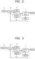
- FIG. 2 to FIG. 5 each illustrate a relationship between a type of fuel used in the carbon dioxide conversion device 1 of the embodiment and an amount of gas produced in each unit.
- FIG. 2 a diagram illustrating the amount of gas produced in each unit when hydrogen (H 2 ) is used as fuel in the carbon dioxide conversion device 1 of the embodiment.
- FIG. 3 is a diagram illustrating the amount of gas produced in each unit when methane (CH 4 ) is used as fuel in the carbon dioxide conversion device 1 of the embodiment.
- FIG. 4 is a diagram illustrating the amount of gas produced in each unit when carbon (C) is used as fuel in the carbon dioxide conversion device 1 of the embodiment.
- FIG. 2 a diagram illustrating the amount of gas produced in each unit when hydrogen (H 2 ) is used as fuel in the carbon dioxide conversion device 1 of the embodiment.
- FIG. 3 is a diagram illustrating the amount of gas produced in each unit when methane (CH 4 ) is used as fuel in the carbon dioxide conversion device 1 of the embodiment.
- FIG. 4 is a diagram
- FIG 5 is a diagram illustrating the amount of gas produced in each unit when hydrogen (H 2 ) and carbon monoxide (CO) are used as fuel in the carbon dioxide conversion device 1 of the embodiment.
- the numeric values in each unit indicate the volume of the target gas. In cases of using either fuel, CO 2 can be effectively utilized.
- Some of the water discharged from the second gas-liquid separator 9 may be supplied to the CO 2 electrolysis unit 5. Although not illustrated, some of the water and CO 2 recovered in the second gas-liquid separator 9 can be used as the circulating medium in the oxygen combustion power generation unit 7. Although not illustrated, there are pumps, compressors, blowers, control devices, and other devices to supply fluid between each piece of equipment. To avoid residual oxygen in CO 2 released from the second gas-liquid separator 9, a fuel/oxygen ratio in the oxygen combustion power generation unit 7 is preferably set slightly larger than the equivalent ratio to prevent residual oxygen. Alternatively, a catalytic combustor may be installed upstream or downstream of the second gas-liquid separator 9 to react the residual oxygen with hydrogen or the like. Pt and Pd are used as combustion catalysts.
Landscapes
- Chemical & Material Sciences (AREA)
- Engineering & Computer Science (AREA)
- Organic Chemistry (AREA)
- Electrochemistry (AREA)
- Materials Engineering (AREA)
- Metallurgy (AREA)
- Chemical Kinetics & Catalysis (AREA)
- Inorganic Chemistry (AREA)
- Life Sciences & Earth Sciences (AREA)
- Sustainable Development (AREA)
- Mechanical Engineering (AREA)
- General Engineering & Computer Science (AREA)
- Electrolytic Production Of Non-Metals, Compounds, Apparatuses Therefor (AREA)
- Carbon And Carbon Compounds (AREA)
Abstract
A CO2 conversion device of the embodiment includes: a CO2 supply unit supplying CO2; a CO2 electrolysis unit including a cathode chamber supplied with CO2 from the CO2 supply unit and reducing and converting CO2 into CO and an anode chamber oxidizing substances to be oxidized to produce oxides; a fuel supply unit supplying fuel; an oxygen combustion power generation unit to which O2-CO2-containing gas discharged from the anode chamber of the carbon dioxide electrolysis unit is supplied, the fuel is supplied from the fuel supply unit, and that combusts the O2-CO2-containing gas; a condenser cooling and condensing water vapor-CO2-containing gas discharged from the oxygen combustion power generation unit; and a gas-liquid separator separating a water-CO2 two-phase fluid discharged from the condenser into water and CO2.
Description
- Embodiments disclosed herein relate generally to a carbon dioxide conversion device.
- Carbon dioxide (CO2) generated by combustion of fossil fuels such as natural gas, coal, and petroleum is considered a major cause of global warming due to the greenhouse effect, and there is a need to reduce the use of fossil fuels. CO2 is removed from exhaust gas emitted from CO2 generation sources, and chemical synthesis is performed using the CO2 removed from the exhaust gas as feedstock. As part of this process, a carbon dioxide conversion device (electrolytic device) that electrolyzes CO2 and water (H2O) to produce carbon monoxide (CO) and oxygen (O2) is being developed. In the carbon dioxide conversion device, the produced CO and approximately a similar amount of CO2 are moved to an oxygen-producing side and released with the oxygen. As a result, an effective utilization rate of CO2 supplied to the carbon dioxide conversion device is as low as 50% or less. Therefore, there is a need to reduce the release of CO2 into the atmosphere and to increase the effective utilization rate of CO2.
- A subject to be solved by the aspects of the invention is to provide a carbon dioxide conversion device that reduces release of CO2 into the atmosphere and increases an effective utilization rate of CO2.
- According to the aspects of the present invention, there is provided a carbon dioxide conversion device which makes it possible to reduce release of CO2 into the atmosphere and increase an effective utilization rate of CO2.
-
-
FIG. 1 is a diagram illustrating a carbon dioxide conversion device of an embodiment. -
FIG. 2 is a diagram illustrating gases produced by each unit and amounts of gases produced when hydrogen (H2) is used as fuel in the carbon dioxide conversion device of the embodiment. -
FIG. 3 is a diagram illustrating gases produced by each unit and amounts of gases produced when methane (CH4) is used as fuel in the carbon dioxide conversion device of the embodiment. -
FIG. 4 is a diagram illustrating gases produced by each unit and amounts of gases produced when carbon (C) is used as fuel in the carbon dioxide conversion device of the embodiment. -
FIG. 5 is a diagram illustrating gases produced by each unit and amounts of gases produced when hydrogen (H2) and carbon monoxide (CO) are used as fuel in the carbon dioxide conversion device of the embodiment. - The carbon dioxide conversion device of the embodiment includes: a carbon dioxide supply unit that supplies carbon dioxide; a carbon dioxide electrolysis unit that includes a cathode chamber where carbon dioxide is supplied from the carbon dioxide supply unit and reduces and converts the carbon dioxide into carbon monoxide and an anode chamber that oxidizes substances to be oxidized to produce oxides; a fuel supply unit that supplies fuel; an oxygen combustion power generation unit to which oxygen-carbon dioxide-containing gas discharged from the anode chamber of the carbon dioxide electrolysis unit is supplied, the fuel is supplied from the fuel supply unit, and that combusts the oxygen-carbon dioxide-containing gas; a condenser that cools and condenses water vapor-carbon dioxide-containing gas discharged from the oxygen combustion power generation unit; and a gas-liquid separator that separates a water-carbon dioxide two-phase fluid discharged from the condenser into water and carbon dioxide.
- Carbon dioxide conversion devices in embodiments will be described hereinafter with reference to the drawings. Substantially the same components are denoted by the same reference signs and explanation thereof may be omitted in some cases in the embodiments described below. The drawings are schematic, and a relationship between a thickness and a planar size, thickness proportions of the respective portions, and the like are sometimes different from actual ones. The "~" symbol in the following explanation indicates a range between upper and lower limit values of the respective numerical values. In such cases, each numerical value range includes the upper and lower limit values.
-
FIG. 1 is a diagram illustrating a carbon dioxide conversion device of an embodiment. The carbon dioxide (CO2)conversion device 1 illustrated inFIG. 1 includes a CO2 supply unit 2 that supplies CO2; a CO2 electrolysis unit 5 that includes acathode chamber 3 reducing and converting CO2 into carbon monoxide (CO) and ananode chamber 4 that oxidizes substances to be oxidized to produce oxides; afuel supply unit 6 that supplies fuel; an oxygen combustionpower generation unit 7 to which oxygen (O2)-carbon dioxide (CO2)-containing gas discharged from theanode chamber 4 of the CO2 electrolysis unit 2 is supplied, the fuel is supplied from thefuel supply unit 6, and that combusts the O2-CO2-containing gas; acondenser 8 that cools and condenses water vapor (H2O)-carbon dioxide (CO2)-containing gas discharged from the oxygen combustionpower generation unit 7; and a gas-liquid separator 9 that separates a water (H2O)-carbon dioxide (CO2) two-phase fluid discharged from thecondenser 8 into water (H2O) and carbon dioxide (CO2). - As the CO2 supply unit 2, a device that recovers and supplies CO2 from carbon dioxide (CO2)-containing gas or a CO2 storage unit is used. For example, the CO2 supply unit 2 is configured to separate and recover CO2 from CO2-containing emission gas (CO2-containing gas) G1 emitted from thermal power plants, waste incineration plants, steel plants, and other plants, and supply CO2 gas G2 with increased CO2 concentration to the CO2 electrolysis unit 5. In such CO2 supply unit 2, for example, the following methods can be used: a chemical absorption method using a chemical absorbing liquid such as an amine aqueous solution, a physical absorption method using a physical absorbing liquid such as methanol or a polyethylene glycol solution, a solid absorption method using a solid absorbent such as an amine compound, a membrane separation method using a CO2 separation membrane, a physical adsorption method using zeolite or other inorganic substances as an absorber, a PSA (pressure swing adsorption) method, a TSA (thermal swing adsorption) method, and other methods. For example, in the chemical absorption method and a device using the amine aqueous solution, the emission gas G1 is supplied to an absorption tower where the amine aqueous solution is sprayed, and the amine aqueous solution that has absorbed CO2 is heated in a regeneration tower to recover CO2 emitted from the amine aqueous solution. The CO2 recovery methods and devices applied to the CO2 supply unit 2 are not limited, and various methods and devices that can recover CO2 from the emission gas G1 can be used.
- The CO2 electrolysis unit 5 is a CO2 electrolytic device with an electrolysis cell and includes a cathode chamber (reduction portion) 3 and an anode chamber (oxidation portion) 4. The
cathode chamber 3 includes a reduction electrode (cathode) and theanode chamber 4 includes an oxidation electrode (anode), and an electrolytic solution is circulated or filled in at least theanode chamber 4. In thecathode chamber 3, CO2 gas may be circulated or a CO2 containing electrolytic solution may be circulated or filled. In thecathode chamber 3 oranode chamber 4, the electrolytic solution is a solution using water (H2O), for example, an aqueous solution containing any electrolyte. Examples of the aqueous solutions containing electrolytes include aqueous solutions containing phosphate ions (PO4 2-), borate ions (BO3 3-), sodium ions (Na+), potassium ions (K+), calcium ions (Ca2+), lithium ions (Li+), cesium ions (Cs+), magnesium ions (Mg2+), chloride ions (Cl-), hydrogen carbonate ions (HCO3 -), carbonate ions (CO3 2-), hydroxide ions (OH-), and other ions. Concrete examples of the electrolytic solutions include alkaline aqueous solutions in which KOH, KHCO3, K2CO3, and the like are dissolved. - The
cathode chamber 3 is supplied with the CO2 gas G2 from the CO2 supply unit 2. Thecathode chamber 3 has a gas flow path facing the non-illustrated reduction electrode, and the CO2 gas is supplied to the gas flow path. Theanode chamber 4 has a liquid flow path facing the non-illustrated oxidation electrode, and the electrolytic solution is supplied to the liquid flow path. A non-illustrated power supply is connected to the reduction and oxidation electrodes. Thecathode chamber 3 andanode chamber 4 are separated from each other by adiaphragm 10 capable of moving ions such as hydrogen ions (H+), hydroxide ions (OH-), carbonate ions (CO3 2-), hydrogen carbonate ions (HCO3 -), and other ions, for example, an ion exchange membrane. The CO2 electrolysis unit 5 may be a single electrolysis cell, have a structure in which the single electrolysis cells are connected in a plane direction, or a stack structure in which a plurality of electrolysis cells are stacked and integrated. - In the
cathode chamber 3 andanode chamber 4 of the CO2 electrolysis unit 5, the following reactions occur. In thecathode chamber 3, an electrolytic reaction and reduction reaction of CO2 occur as shown in formula (1) below. In thecathode chamber 3, the reduction reaction of CO2 produces CO and carbonate ions (CO3 2-).
2CO2 + 2e- → CO + CO3 2- ... (1)
- The carbonate ions (CO3 2-) produced in the
cathode chamber 3 move to theanode chamber 4 through thediaphragm 10. In theanode chamber 4, as shown in formula (2) below, an oxidation reaction of the carbonate ions (CO3 2-) produced in thecathode chamber 3 and moved through thediaphragm 10 occurs, resulting in production of CO2 and O2.
CO3 2- → CO2 + 0.5O2 + 2e- ... (2)
- Furthermore, in the
cathode chamber 3, the electrolytic reaction (reduction reaction) of H2O in the electrolytic solution occurs simultaneously with the electrolytic reaction (reduction reaction) of CO2, producing hydrogen (H2) and hydroxide ions (OH-), as shown in formula (3) below.
2H2O + 2e- → H2 + 2OH- ... (3)
- The hydroxide ions (OH-) produced in the
cathode chamber 3 move to theanode chamber 4 through thediaphragm 10. Water (H2O) and oxygen (O2) are then produced in theanode chamber 4, as shown in formula (4) below.
2OH- → 0.5O2 + H2O + 2e- ... (4)
- In the
anode chamber 4, water (H2O) in the electrolytic solution is electrolyzed to produce oxygen (O2) and hydrogen ions (H+), as shown in formula (5) below.
2H2O → 4H+ + O2 + 4e- ... (5)
- The produced hydrogen ions (H+) move to the
cathode chamber 3 through thediaphragm 10. In thecathode chamber 3 where hydrogen ions (H+) reach and electrons (e-) reach through external circuits, hydrogen is generated by the reaction shown in formula (6) below.
4H+ + 4e- → 2H2 ... (6)
- In the
cathode chamber 3, CO is produced by the reduction reaction of CO2 as shown in formula (1), and H2 is produced by the electrolytic reaction of H2O as shown in formula (3) and the reaction shown in formula (6). CO and H2 produced in thecathode chamber 3 are discharged from thecathode chamber 3 together with unreacted CO2. Mixed gas G3 containing CO and H2, and CO2 discharged from thecathode chamber 3 is supplied to anorganic synthesis unit 11, for example, as part of source gas for an organic synthesis reaction. Hydrogen (H2) is supplied to theorganic synthesis unit 11 as needed, in addition to the mixed gas G3 containing CO and H2, as part of the source gas for the organic synthesis reaction. - In the
organic synthesis unit 11, the organic synthesis reactions are performed, for example, using the Fischer-Tropsch synthesis reaction to synthesize hydrocarbons, alcohols, and other organic substances, for example. Concrete examples of the organic substances synthesized in theorganic synthesis unit 11 include carbon-containing liquid fuels, or the like. The products (organic substances) of theorganic synthesis unit 11 are discharged from theorganic synthesis unit 11 and sent, for example, to a separately installed tank or other storage facility (not illustrated). - Meanwhile, in the
anode chamber 4 of the CO2 electrolysis unit 5, oxygen (O2) and carbon dioxide (CO2) are produced by oxidation of carbonate ions (CO3 2-) and hydroxide ions (OH-), as shown in formulas (2) and (4) above. The gas containing O2 and CO2 (O2-CO2-containing gas) produced in theanode chamber 4 is discharged from theanode chamber 4 together with the electrolytic solution. An electrolytic solution VL1 containing the O2-CO2-containing gas is sent to a first gas-liquid separation unit 12, which is connected to a discharge pipe of theanode chamber 4, and O2-CO2-containing gas G4 is separated from the electrolytic solution. The separated electrolytic solution is returned to theanode chamber 4, though not illustrated. Since a CO2 concentration of the separated O2-CO2-containing gas G4 is as high as 60 volume% or more, effective utilization of CO2 would be hindered when the gas G4 is directly released into the atmosphere. Furthermore, since the O2-CO2-containing gas G4 contains a relatively large amount of O2, operation and function of the CO2 electrolysis unit 5 will be degraded when it is sent directly to thecathode chamber 3. The O2-CO2-containing gas G4 discharged from theanode chamber 4 of the CO2 electrolysis unit 5 and separated and recovered in the first gas-liquid separation unit 12 is sent to the oxygen combustionpower generation unit 7. - Closed-cycle gas turbines, turbine combined cycle power generation, Graz cycle gas turbines, supercritical CO2 turbines, oxy-fuel combustion devices, and the like can be used as the oxygen combustion
power generation unit 7. These can efficiently combust and consume O2 in the O2-CO2-containing gas using hydrogen or the like as fuel, and can also efficiently operate gas turbines or the like based on combustion, so that electric power can be generated using O2 in the O2-CO2-containing gas as an oxidant. The electric power generated by the oxygen combustionpower generation unit 7 can be used as part of operating power of the CO2 electrolysis unit 5. - To combust and consume the O2-CO2-containing gas in a combustion reaction in the oxygen combustion
power generation unit 7, fuel is supplied to the oxygen combustionpower generation unit 7 from thefuel supply unit 6 in addition to the O2-CO2-containing gas G4. The fuel supplied from thefuel supply unit 6 is not limited, and may be any of hydrogen (H2), carbon (C), carbon monoxide (CO), and lower hydrocarbons such as methane (CH4). Thefuel supply unit 6 may be an oxygen-blown gasification furnace or the like. The fuel supplied from thefuel supply unit 6 is preferably supplied in an equivalent ratio to O2 in the O2-CO2 containing gas. In the oxygen combustionpower generation unit 7, O2 is converted into H2O or CO2. For example, when hydrogen (H2) is supplied as the fuel, H2O is produced. When carbon (C) or carbon monoxide (CO) is supplied as the fuel, CO2 is produced. The same is true when methane (CH4) or other fuels are supplied, and H2O and CO2 are produced. The produced CO2 is recovered simultaneously with CO2 in the O2-CO2-containing gas. - When the closed-cycle gas turbines, turbine combined cycle power generation, Graz cycle gas turbines, supercritical CO2 turbines, oxy-fuel combustion devices, and the like are used as the oxygen combustion
power generation unit 7, simply supplying fuel for combustion will result in higher temperatures in the oxygen combustionpower generation unit 7. In contrast, using the produced H2O (for example, water vapor) or CO2 as a circulating medium can suppress the temperature rise of the oxygen combustionpower generation unit 7. For example, H2O and CO2 are used as the circulating media in the closed-cycle gas turbines, turbine combined cycle power generation, and Graz cycle gas turbines. In the supercritical CO2 turbines and oxy-fuel combustion devices, CO2 is used as the circulating medium. These allow the oxygen combustionpower generation unit 7 to operate safely and efficiently. - H2O (water vapor)-CO2-containing gas G5 is discharged from the oxygen combustion
power generation unit 7. The H2O (water vapor)-CO2-containing gas G5 is sent to thecondenser 8 to be cooled and water vapor (H2O) is condensed to be converted into water. A water (H2O)-carbon dioxide (CO2) two-phase fluid VL2 containing water from the condensation of water vapor (H2O) is discharged from thecondenser 8. The H2O-CO2 two-phase fluid VL2 is sent to a second gas-liquid separator 9. In the second gas-liquid separator 9, water in the H2O-CO2 two-phase fluid VL2 is separated. At least some of the separated water (H2O) may be used as part of the electrolytic solution supplied to theanode chamber 4 of the CO2 electrolysis unit, or may be returned to the oxygen combustionpower generation unit 7 as the circulating medium. CO2 gas G6 separated in the second gas-liquid separator 9 is sent to agas mixer 13. Thegas mixer 13 is connected to thecathode chamber 3 of the CO2 electrolysis unit 5. In thegas mixer 13, the CO2 gas G6 separated in the second gas-liquid separator 9 is mixed with the CO2 gas G2 and supplied to thecathode chamber 3. At least one of the water and CO2 discharged from the second gas-liquid separator 9 may be used as the circulating medium in the oxygen combustionpower generation unit 7. - As described above, the CO2 gas that is produced as a by-product in the
anode chamber 4 and separated in the second gas-liquid separator 9 can be returned to thecathode chamber 3 of the CO2 electrolysis unit 5, with operation failure and functional degradation and the like in thecathode chamber 3 under control, by combusting the O2-CO2-containing gas G4 discharged from theanode chamber 4 of the CO2 electrolysis unit 5 in the oxygen combustionpower generation unit 7 to convert O2 in the O2-CO2-containing gas G4 into H2O and CO2. Furthermore, O2 in the O2-CO2-containing gas G4 can be regenerated as CO2. These features make it possible to reduce release of CO2 into the atmosphere in the carbondioxide conversion device 1, increase an effective utilization rate of CO2, and improve device utilization efficiency. -
FIG. 2 to FIG. 5 each illustrate a relationship between a type of fuel used in the carbondioxide conversion device 1 of the embodiment and an amount of gas produced in each unit.FIG. 2 a diagram illustrating the amount of gas produced in each unit when hydrogen (H2) is used as fuel in the carbondioxide conversion device 1 of the embodiment.FIG. 3 is a diagram illustrating the amount of gas produced in each unit when methane (CH4) is used as fuel in the carbondioxide conversion device 1 of the embodiment.FIG. 4 is a diagram illustrating the amount of gas produced in each unit when carbon (C) is used as fuel in the carbondioxide conversion device 1 of the embodiment.FIG. 5 is a diagram illustrating the amount of gas produced in each unit when hydrogen (H2) and carbon monoxide (CO) are used as fuel in the carbondioxide conversion device 1 of the embodiment. In these figures, the numeric values in each unit indicate the volume of the target gas. In cases of using either fuel, CO2 can be effectively utilized. - Some of the water discharged from the second gas-
liquid separator 9 may be supplied to the CO2 electrolysis unit 5. Although not illustrated, some of the water and CO2 recovered in the second gas-liquid separator 9 can be used as the circulating medium in the oxygen combustionpower generation unit 7. Although not illustrated, there are pumps, compressors, blowers, control devices, and other devices to supply fluid between each piece of equipment. To avoid residual oxygen in CO2 released from the second gas-liquid separator 9, a fuel/oxygen ratio in the oxygen combustionpower generation unit 7 is preferably set slightly larger than the equivalent ratio to prevent residual oxygen. Alternatively, a catalytic combustor may be installed upstream or downstream of the second gas-liquid separator 9 to react the residual oxygen with hydrogen or the like. Pt and Pd are used as combustion catalysts. - The configurations in the embodiments can be applied in combination and partially replaced. While certain embodiments of the present invention have been described herein, these embodiments have been presented by way of example only, and are not intended to limit the scope of the inventions. The embodiments described herein may be embodied in a variety of other forms; furthermore, various omissions, substitutions, and changes may be made without departing from the spirit of the inventions. The embodiments and modifications fall within the scope and spirit of the inventions and fall within the scope of the inventions as set forth in claims and their equivalents.
Claims (6)
- A carbon dioxide conversion device, comprising:a carbon dioxide supply unit that supplies carbon dioxide;a carbon dioxide electrolysis unit that includes a cathode chamber where carbon dioxide is supplied from the carbon dioxide supply unit and reduces and converts the carbon dioxide into carbon monoxide and an anode chamber that oxidizes substances to be oxidized to produce oxides;a fuel supply unit that supplies fuel;an oxygen combustion power generation unit to which oxygen-carbon dioxide-containing gas discharged from the anode chamber of the carbon dioxide electrolysis unit is supplied, the fuel is supplied from the fuel supply unit, and that combusts the oxygen-carbon dioxide-containing gas;a condenser that cools and condenses water vapor-carbon dioxide-containing gas discharged from the oxygen combustion power generation unit; anda gas-liquid separator that separates a water-carbon dioxide two-phase fluid discharged from the condenser into water and carbon dioxide.
- The device according to claim 1, wherein
the gas-liquid separator is configured to supply carbon dioxide separated from the water-carbon dioxide two-phase fluid to the cathode chamber of the carbon dioxide electrolysis unit. - The device according to claim 1, wherein
the gas-liquid separator is configured to supply at least some of the separated water to the anode chamber of the carbon dioxide electrolysis unit as part of an electrolytic solution. - The device according to any one of claim 1 to claim 3, wherein
the oxygen combustion power generation unit includes a closed-cycle gas turbine, turbine combined cycle power generation, Graz cycle gas turbine, supercritical CO2 turbine, or oxy-fuel combustion device. - The device according to claim 4, wherein
at least one of water and carbon dioxide produced by combustion and carbon dioxide in the oxygen-carbon dioxide-containing gas is supplied as a circulating medium for the oxygen combustion power generation unit. - The device according to claim 4, wherein
at least one of water and carbon dioxide discharged from the gas-liquid separator is supplied as a circulating medium for the oxygen combustion power generation unit.
Applications Claiming Priority (1)
| Application Number | Priority Date | Filing Date | Title |
|---|---|---|---|
| JP2023046821A JP2024135916A (en) | 2023-03-23 | 2023-03-23 | Carbon Dioxide Conversion Device |
Publications (1)
| Publication Number | Publication Date |
|---|---|
| EP4435148A1 true EP4435148A1 (en) | 2024-09-25 |
Family
ID=89707981
Family Applications (1)
| Application Number | Title | Priority Date | Filing Date |
|---|---|---|---|
| EP24153442.9A Pending EP4435148A1 (en) | 2023-03-23 | 2024-01-23 | Carbon dioxide conversion device |
Country Status (3)
| Country | Link |
|---|---|
| US (1) | US20240318340A1 (en) |
| EP (1) | EP4435148A1 (en) |
| JP (1) | JP2024135916A (en) |
Citations (2)
| Publication number | Priority date | Publication date | Assignee | Title |
|---|---|---|---|---|
| EP3670705A1 (en) * | 2018-12-21 | 2020-06-24 | L'air Liquide, Societe Anonyme Pour L'etude Et L'exploitation Des Procedes Georges Claude | Carbon dioxide conversion process |
| US20230020698A1 (en) * | 2019-12-20 | 2023-01-19 | Siemens Energy Global GmbH & Co. KG | Apparatus and method for utilizing off-gases from a power-to-x system |
Family Cites Families (5)
| Publication number | Priority date | Publication date | Assignee | Title |
|---|---|---|---|---|
| JP2517799B2 (en) * | 1991-04-01 | 1996-07-24 | 株式会社日立製作所 | Electrochemical exhaust gas treatment system |
| JP7297710B2 (en) * | 2020-03-23 | 2023-06-26 | 株式会社東芝 | carbon dioxide reactor |
| JP2022068715A (en) * | 2020-10-22 | 2022-05-10 | 株式会社東芝 | Power generation system |
| JP2022110310A (en) * | 2021-01-18 | 2022-07-29 | 株式会社日立製作所 | Combustor system and method for starting and stopping the same |
| JP7176025B2 (en) * | 2021-03-11 | 2022-11-21 | 本田技研工業株式会社 | generator |
-
2023
- 2023-03-23 JP JP2023046821A patent/JP2024135916A/en active Pending
-
2024
- 2024-01-22 US US18/418,780 patent/US20240318340A1/en active Pending
- 2024-01-23 EP EP24153442.9A patent/EP4435148A1/en active Pending
Patent Citations (2)
| Publication number | Priority date | Publication date | Assignee | Title |
|---|---|---|---|---|
| EP3670705A1 (en) * | 2018-12-21 | 2020-06-24 | L'air Liquide, Societe Anonyme Pour L'etude Et L'exploitation Des Procedes Georges Claude | Carbon dioxide conversion process |
| US20230020698A1 (en) * | 2019-12-20 | 2023-01-19 | Siemens Energy Global GmbH & Co. KG | Apparatus and method for utilizing off-gases from a power-to-x system |
Also Published As
| Publication number | Publication date |
|---|---|
| US20240318340A1 (en) | 2024-09-26 |
| JP2024135916A (en) | 2024-10-04 |
Similar Documents
| Publication | Publication Date | Title |
|---|---|---|
| KR101142472B1 (en) | Molten Carbonate Fuel Cell System with Hydrocarbon Reactor | |
| JP7297710B2 (en) | carbon dioxide reactor | |
| JPWO2008096623A1 (en) | Power generation equipment | |
| JP7686552B2 (en) | Carbon dioxide conversion device and carbon dioxide conversion method | |
| JP3108079B2 (en) | Fuel cell, carbon dioxide fixed combined power generation method | |
| EP2800188B1 (en) | Combined generation system and method for collecting carbon dioxide for combined generation system | |
| JP6692394B2 (en) | Carbon recovery fuel cell power generation system | |
| KR101438110B1 (en) | Combined power generation system | |
| US20240318340A1 (en) | Carbon dioxide conversion device | |
| JP2022189815A (en) | Hybrid power plant with CO2 capture | |
| US20240360568A1 (en) | Carbon monoxide production device, carbon dioxide electrolysis device, and carbon dioxide electrolysis method | |
| KR101408143B1 (en) | Combined power generation system and method for capturing carbon dioxide in the combined power generation system | |
| JP7666869B2 (en) | Carbon Dioxide Treatment Equipment | |
| CN118669190B (en) | A power generation system for a combined cycle unit coupled with a molten carbonate electrolyzer | |
| JP2011103213A (en) | Power generation system | |
| JP2023079603A (en) | Carbon monoxide production equipment | |
| KR101438109B1 (en) | Combined power generation system and method for capturing carbon dioxide in the combined power generation system | |
| JP5477677B2 (en) | Power generation equipment | |
| JP7830265B2 (en) | Carbon dioxide conversion device | |
| JP7858474B2 (en) | Carbon monoxide production device | |
| JP2022110310A (en) | Combustor system and method for starting and stopping the same | |
| JP7840894B2 (en) | Carbon dioxide conversion device and carbon dioxide conversion method | |
| JP2024126545A (en) | Carbon dioxide conversion device and carbon dioxide conversion method | |
| JP2011103212A (en) | Power generation system | |
| JP7117191B2 (en) | Carbon dioxide capture fuel cell power generation system |
Legal Events
| Date | Code | Title | Description |
|---|---|---|---|
| PUAI | Public reference made under article 153(3) epc to a published international application that has entered the european phase |
Free format text: ORIGINAL CODE: 0009012 |
|
| STAA | Information on the status of an ep patent application or granted ep patent |
Free format text: STATUS: REQUEST FOR EXAMINATION WAS MADE |
|
| 17P | Request for examination filed |
Effective date: 20240123 |
|
| AK | Designated contracting states |
Kind code of ref document: A1 Designated state(s): AL AT BE BG CH CY CZ DE DK EE ES FI FR GB GR HR HU IE IS IT LI LT LU LV MC ME MK MT NL NO PL PT RO RS SE SI SK SM TR |