EP4434824A1 - Universal wiper base assembly structure - Google Patents
Universal wiper base assembly structure Download PDFInfo
- Publication number
- EP4434824A1 EP4434824A1 EP23164033.5A EP23164033A EP4434824A1 EP 4434824 A1 EP4434824 A1 EP 4434824A1 EP 23164033 A EP23164033 A EP 23164033A EP 4434824 A1 EP4434824 A1 EP 4434824A1
- Authority
- EP
- European Patent Office
- Prior art keywords
- base
- wiper
- assembly structure
- main body
- fastening
- Prior art date
- Legal status (The legal status is an assumption and is not a legal conclusion. Google has not performed a legal analysis and makes no representation as to the accuracy of the status listed.)
- Granted
Links
Images


Classifications
-
- B—PERFORMING OPERATIONS; TRANSPORTING
- B60—VEHICLES IN GENERAL
- B60S—SERVICING, CLEANING, REPAIRING, SUPPORTING, LIFTING, OR MANOEUVRING OF VEHICLES, NOT OTHERWISE PROVIDED FOR
- B60S1/00—Cleaning of vehicles
- B60S1/02—Cleaning windscreens, windows or optical devices
- B60S1/04—Wipers or the like, e.g. scrapers
- B60S1/32—Wipers or the like, e.g. scrapers characterised by constructional features of wiper blade arms or blades
- B60S1/40—Connections between blades and arms
- B60S1/4003—Multi-purpose connections for two or more kinds of arm ends
-
- B—PERFORMING OPERATIONS; TRANSPORTING
- B60—VEHICLES IN GENERAL
- B60S—SERVICING, CLEANING, REPAIRING, SUPPORTING, LIFTING, OR MANOEUVRING OF VEHICLES, NOT OTHERWISE PROVIDED FOR
- B60S1/00—Cleaning of vehicles
- B60S1/02—Cleaning windscreens, windows or optical devices
- B60S1/04—Wipers or the like, e.g. scrapers
- B60S1/32—Wipers or the like, e.g. scrapers characterised by constructional features of wiper blade arms or blades
- B60S1/40—Connections between blades and arms
- B60S1/4067—Connections between blades and arms for arms provided with a side pin
- B60S1/407—Connections between blades and arms for arms provided with a side pin with means provided on the arm for locking the side pin
-
- B—PERFORMING OPERATIONS; TRANSPORTING
- B60—VEHICLES IN GENERAL
- B60S—SERVICING, CLEANING, REPAIRING, SUPPORTING, LIFTING, OR MANOEUVRING OF VEHICLES, NOT OTHERWISE PROVIDED FOR
- B60S1/00—Cleaning of vehicles
- B60S1/02—Cleaning windscreens, windows or optical devices
- B60S1/04—Wipers or the like, e.g. scrapers
- B60S1/32—Wipers or the like, e.g. scrapers characterised by constructional features of wiper blade arms or blades
- B60S1/40—Connections between blades and arms
- B60S1/4038—Connections between blades and arms for arms provided with a channel-shaped end
- B60S1/4045—Connections between blades and arms for arms provided with a channel-shaped end comprising a detachable intermediate element mounted on the channel-shaped end
- B60S1/4048—Connections between blades and arms for arms provided with a channel-shaped end comprising a detachable intermediate element mounted on the channel-shaped end the element being provided with retention means co-operating with the channel-shaped end of the arm
- B60S2001/4051—Connections between blades and arms for arms provided with a channel-shaped end comprising a detachable intermediate element mounted on the channel-shaped end the element being provided with retention means co-operating with the channel-shaped end of the arm the intermediate element engaging the side walls of the arm
-
- B—PERFORMING OPERATIONS; TRANSPORTING
- B60—VEHICLES IN GENERAL
- B60S—SERVICING, CLEANING, REPAIRING, SUPPORTING, LIFTING, OR MANOEUVRING OF VEHICLES, NOT OTHERWISE PROVIDED FOR
- B60S1/00—Cleaning of vehicles
- B60S1/02—Cleaning windscreens, windows or optical devices
- B60S1/04—Wipers or the like, e.g. scrapers
- B60S1/32—Wipers or the like, e.g. scrapers characterised by constructional features of wiper blade arms or blades
- B60S1/40—Connections between blades and arms
- B60S1/4038—Connections between blades and arms for arms provided with a channel-shaped end
- B60S1/4045—Connections between blades and arms for arms provided with a channel-shaped end comprising a detachable intermediate element mounted on the channel-shaped end
- B60S1/4048—Connections between blades and arms for arms provided with a channel-shaped end comprising a detachable intermediate element mounted on the channel-shaped end the element being provided with retention means co-operating with the channel-shaped end of the arm
- B60S2001/4054—Connections between blades and arms for arms provided with a channel-shaped end comprising a detachable intermediate element mounted on the channel-shaped end the element being provided with retention means co-operating with the channel-shaped end of the arm the intermediate element engaging the back part of the arm
-
- B—PERFORMING OPERATIONS; TRANSPORTING
- B60—VEHICLES IN GENERAL
- B60S—SERVICING, CLEANING, REPAIRING, SUPPORTING, LIFTING, OR MANOEUVRING OF VEHICLES, NOT OTHERWISE PROVIDED FOR
- B60S1/00—Cleaning of vehicles
- B60S1/02—Cleaning windscreens, windows or optical devices
- B60S1/04—Wipers or the like, e.g. scrapers
- B60S1/32—Wipers or the like, e.g. scrapers characterised by constructional features of wiper blade arms or blades
- B60S1/40—Connections between blades and arms
- B60S1/4038—Connections between blades and arms for arms provided with a channel-shaped end
- B60S2001/4058—Connections between blades and arms for arms provided with a channel-shaped end comprising a separate locking element, e.g. in addition to an intermediate element
Definitions
- the present disclosure relates to a windscreen wiper, and in particular, to a wiper base assembly structure for accommodating a variety of wiper driving arms.
- car windscreen wipers need to be assembled on outer sides of car windscreens by connecting wiper driving arms.
- the wiper driving arms exert force on wiper rubber strips (or blades) to scrape off the rain or stains on glass surfaces by driving the wipers to swing back and forth on the glass surfaces.
- the wiper driving arm is usually mounted and fixed on a wiper base assembly structure.
- wiper driving arms provided by automobile manufacturers to match different automobile model. Therefore, in order to accommodate all kinds of wiper driving arms, the wipers need various specific base assembly structure.
- most windscreen wiper manufacturers provide multiple base assemblies to allow users to choose a suitable base assembly for assembling. However, this not only increases an overall price of the wiper, but also wastes components, which is a problem needs to be solved.
- a variety of the wiper driving arms may be positioned through the fastening base being selectively coupled with the rear base, the combination base, or/and the outer cover to increase conveniences during using.
- the present disclosure provides a universal wiper base assembly structure for accommodating a variety of wiper driving arms, the universal wiper base assembly including: a fastening base, a rear base, a combination base, and an outer cover.
- the fastening base includes a main body and a decorative cover.
- the main body includes a coupling hole defined at a bottom, an insertion slot defined at a top, a protruding platform, a positioning protrusion disposed on the protruding platform, a first shaft hole defined at a lateral side, two limiting arc surfaces disposed on opposite sides, and a plurality of engagement grooves defined on a bottom surface.
- the decorative cover is rotatably connected to a front side of the main body and includes a fastening slot.
- the rear base includes two contact blocks disposed on opposite sides, a top abutting block abutting against the positioning protrusion, a trench defined in front of the top abutting block, and two hooks disposed in front of the top abutting block.
- the rear base is detachably coupled to a rear side of the main body through the two hooks being engaged with the main body.
- the combination base is detachably coupled to a top surface of the main body and positioned in the trench.
- the combination base includes two side plates, a connection plate located between the two side plates, and an open groove defined at a position corresponding to the protruding platform and the positioning protrusion.
- Each of the side plates includes a second shaft hole defined at a position corresponding to the first shaft hole.
- the outer cover includes a fastening block, an opening exposing the protruding platform and the positioning protrusion and a third shaft hole defined at a position corresponding to one of the second shaft holes.
- the outer cover is removably fixed to the combination base by the fastening block being engaged with the fastening slot.
- the variety of the wiper driving arms are positioned through the fastening base selectively being coupled with the rear base, the combination base, or/and the outer cover.
- the universal wiper base assembly structure of the present application includes a fastening base, a rear base, a combination base, and an outer cover.
- the fastening base includes positioning structures such as a coupling hole, an insertion slot, a protruding platform, a positioning protrusion, a first shaft hole, multiple limiting arc surfaces, multiple engagement grooves, and a fastening slot.
- the rear base includes positioning structures such as multiple contact blocks, a top abutting block, and two hooks.
- the combination base includes an open groove and a second shaft hole.
- the outer cover includes a fastening block, an opening, and a third shaft hole. Accordingly, a variety of wiper driving arms may be positioned through the fastening base being selectively coupled with the rear base, the combination base, or/and the outer cover, so as to improve the convenience in assembling and reduce an overall cost of the wiper.
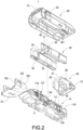
- FIGS. 1 to 3 are perspective exploded views showing a universal wiper base assembly structure of the present disclosure viewed from two side directions and a perspective appearance view showing the universal wiper base assembly structure of the present disclosure.
- the present disclosure is a universal wiper base assembly structure 1, which includes a fastening base 10, a rear base 20, a combination base 30, and an outer cover 40.
- the rear base 20, the combination base 30, and the outer cover 40 may be selectively coupled to the fastening base 10, so as to position and couple a variety of wiper driving arms.
- a more detailed description of the universal wiper base assembly structure 1 is provided below.
- the fastening base 10 includes a main body 11 and a decorative cover 12.
- the main body 11 includes a coupling hole 111 at a bottom, an insertion slot 112 at a top, a protruding platform 114, a positioning protrusion 115 arranged on the protruding platform 114, a first shaft hole 116 at a lateral side, two limiting arc surfaces 117 disposed on opposite sides, and a plurality of engagement grooves 118 on a bottom surface.
- the decorative cover 12 is rotatably connected to a front side of the main body 11 and includes a fastening slot 121.
- the main body 11 is provided with an engagement plate 119 in front of each of the limiting arc surfaces 117.
- the decorative cover 12 includes two wing plates 122. Each of the wing plates 122 is provided with an engagement slot 123. The decorative cover 12 is fastened to the main body 11 through the engagement slots 123 being engaged with the engagement plates 119 (see also FIG. 4 ).
- each wing plate 122 includes a positioning arc surface 124. Each of the limiting arc surfaces 117 abuts against the positioning arc surface 124 of one of the wing plates 122.
- the rear base 20 includes two contact blocks 21 disposed on opposite sides, a top abutting block 22 abutting against the positioning protrusion 115, a trench 23 defined in front of the top abutting block 22, and two hooks 24 arranged in front of the top abutting block 22.
- the rear base 20 is detachably coupled to a rear side of the main body 11 through the two hooks 24 being engaged with the main body 11.
- the main body 11 is provided with two insertion grooves 110 defined on a rear side of the positioning protrusion 115.
- the rear base 20 is provided with two insertion plates 25 disposed on one side of the trench 23. The two insertion plates 25 are inserted in the two insertion grooves 110.
- the rear base 20 includes two abutting surfaces 26 located in front of the two abutting blocks 21. An insertion recess 27 contacting a sidewall of the main body 11 is defined between each of the abutting surfaces 26 and each of the insertion plates 25.
- the main body 11 includes two blocking plates 1101 disposed on two sides of the protruding platform 114. Further, an end surface of the rear base 20 abuts against the two blocking plates 1101.
- the combination base 30 is detachably coupled to a top surface of the main body 11 and positioned in the trench 23.
- the combination base 30 includes two side plates 31, a connection plate 32 located between the two side plates 31, and an open groove 33 defined at a position corresponding to the protruding platform 114 and the positioning protrusion 115.
- Each of the side plates 31 includes a second shaft hole 34 defined at a position corresponding to the first shaft hole 116.
- the combination base 30 is provided with a plurality of protruding ribs 35 on inner sides of the two side plates 31.
- the protruding ribs 35 are positioned in the engagement grooves 118 of the main body 11.
- the outer cover 40 covers the combination base 30.
- the outer cover 40 includes a fastening block 41, an opening 42 exposing the protruding platform 114 and the positioning protrusion 115 and a third shaft hole 43 defined at a position corresponding to the second shaft hole 34.
- the decorative cover 12 is rotatable toward the main body 11.
- the outer cover 40 is removably fixed to the combination base 30 by the fastening block 41 being engaged with the fastening slot 121 (see FIG. 3 ).
- FIG. 4 is a schematic assembling view showing that the universal wiper base assembly structure of the present disclosure is coupled to a wiper base
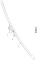
- FIG. 5 is a perspective appearance view showing a wiper of the present disclosure.
- the universal wiper base assembly structure 1 of the present disclosure is configured to be installed on a wiper base 2.
- the wiper base 2 is further combined with a wiper blade 3 to form a wiper.
- FIG. 6 is a schematic assembling view showing that the universal wiper base assembly structure of the present disclosure is coupled to a first wiper driving arm.
- FIG. 7 is a perspective appearance view showing the universal wiper base assembly structure of the present disclosure after assembling.
- the universal wiper base assembly structure 1 is structured by combining the rear base 20, the combination base 30, and the outer cover 40 with the fastening base 10 (see FIG. 3 ).
- the first wiper driving arm 50 includes a first arm body 51, an insertion shaft 52 connected to a lateral side of the first arm body 51, and a span arm 53 transversely extended from a top surface of the first arm body 51.
- the insertion shaft 52 passes through the third shaft hole 43, the second shaft hole 34, and the first shaft hole 116.
- the first arm body 51 abuts against a left side of the fastening base 10, and the span arm 53 straddles the outer cover 40.
- the first wiper driving arm 50 is coupled to the universal wiper base assembly structure 1 to drive the wiper blade 3 to move.
- the universal wiper base assembly structure 1 may also be combined with a right-side-type first wiper driving arm 50 to couple the same on a right side of the fastening base 1.
- FIG. 8 is a schematic assembling view showing that the universal wiper base assembly structure of the present disclosure is coupled to a second wiper driving arm.
- FIG. 9 and FIG. 10 are perspective appearance views from two side directions, showing that the universal wiper base assembly structure of the present disclosure is coupled to the second wiper driving arm.
- the universal wiper base assembly structure 1 is structured by removing the outer cover 40 and the rear base 20, and only coupling the combination base 30 to the fastening base 10.
- the positioning protrusion 115 protrudes from the open groove 33 of the combination base 30.
- a second wiper driving arm 50a includes a second arm body 51a and a shielding cover 52a connected to the second arm body 51a.
- a top of the shielding cover 52a is provided with a fastening hole 520a
- a bottom of the shielding cover 52a is provided with a plurality of hooks 521a
- a front end of the shielding cover 52a is provided with a plurality of positioning end surfaces 522a.
- the shielding cover 52a covers the combination base 30.
- the positioning protrusion 115 passes through the fastening hole 520a.
- the hooks 521a on the bottom of the shielding cover 52a are engaged with the engagement grooves 118 on the bottom of the fastening base 10, and the decorative cover 12 of the fastening base 10 presses the shielding cover 52a.
- the second wiper driving arm 50a is coupled to the universal wiper base assembly structure 1 to drive the wiper blade 3 to move.
- FIG. 11 is a schematic assembling view showing that the universal wiper base assembly structure of the present disclosure is coupled to a third wiper driving arm.
- FIG. 12 is a schematic appearance view showing that the universal wiper base assembly structure of the present disclosure is coupled to the third wiper driving arm.
- the universal wiper base assembly structure 1 is structured by reserving the fastening base 10 and the combination base 30. That is to say, the outer cover 40 and the rear base 20 are removed from the fastening base 10.
- the insertion shaft 52b passes through the third shaft hole 43, and the third arm body 51b abuts against a left side of the fastening base 10.
- the span arm 53b straddles the outer cover 40. Accordingly, the third wiper driving arm 50b is coupled to the universal wiper base assembly structure 1 to drive the wiper blade 3 to move.
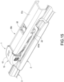
- FIG. 13 is a schematic assembling view showing that the universal wiper base assembly structure of the present disclosure is coupled to a fourth wiper driving arm.
- FIG. 14 and FIG. 15 are perspective appearance views from two side directions, showing that the universal wiper base assembly structure of the present disclosure is coupled to the fourth wiper driving arm.
- the universal wiper base assembly structure 1 is structured by removing the outer cover 40 and the combination base 30, and only combining the rear base 20 with the fastening base 10.
- the fastening base 10 has an insertion slot 112.
- the rear base 20 includes two contact blocks 21 and a top abutting block 22.
- a fourth wiper driving arm 50c includes a fourth arm body 51c, and the fourth arm body 51c is a U-shaped cover.
- the fourth arm body 51c is provided with a protruding plate 511c, an abutting plate 512c, and a limiting plate 513c. It should be noted that the fourth arm body 51c may be dispensed with the abutting plate 512c.
- the fourth arm body 51c covers the fastening base 10 and the rear base 20.
- the protruding plate 511c of the fourth wiper driving arm 50c is inserted into the insertion slot 112 of the fastening base 10, the abutting plate 512c abuts against the top abutting block 22, and the limiting plate 513c abuts against the contact block 21.
- the decorative cover 12 of the fastening base 10 presses the shielding cover 52a. Accordingly, the fourth wiper driving arm 50c is coupled to the universal wiper base assembly structure 1 to drive the wiper blade 3 to move.
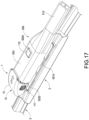
- FIG. 16 is a schematic assembling view showing that the universal wiper base assembly structure of the present disclosure is coupled to a fifth wiper driving arm.
- FIG. 17 and FIG. 18 are perspective appearance views from two side directions, showing that the universal wiper base assembly structure of the present disclosure is coupled to the fifth wiper driving arm.
- the fastening base 10 is reserved in the universal wiper base assembly structure 1. That is to say, the outer cover 40, the combination base 30, and the rear base 20 are removed.
- the fastening base 10 includes two limiting arc surfaces 117 and a plurality of engagement grooves 118 on a bottom surface.
- the fifth wiper driving arm 50d includes a fifth arm body 51d and a shielding cover 52d connected to the fifth arm body 51d.
- the fifth arm body 51d is a U-shaped cover.
- a top of the cover 52d is provided with a fastening hole 520d
- a bottom of the shielding cover 52d is provided with a plurality of hooks 521d
- a front end of the shielding cover 52d is provided with a plurality of positioning end surfaces 522d.
- the shielding cover 52d covers the fastening base 10.
- the positioning protrusion 115 passes through the fastening hole 520d.
- the hooks 521d on the bottom of the shielding cover 52d are engaged with the engagement grooves 118 on the bottom of the fastening base 10, and the decorative cover 12 of the fastening base 10 presses the shielding cover 52d.
- the fifth wiper driving arm 50d is coupled to the universal wiper base assembly structure 1 to drive the wiper blade 3 to move.
Landscapes
- Engineering & Computer Science (AREA)
- Mechanical Engineering (AREA)
- Connection Of Plates (AREA)
- Ink Jet (AREA)
Abstract
Description
- The present disclosure relates to a windscreen wiper, and in particular, to a wiper base assembly structure for accommodating a variety of wiper driving arms.
- Generally, car windscreen wipers need to be assembled on outer sides of car windscreens by connecting wiper driving arms. The wiper driving arms exert force on wiper rubber strips (or blades) to scrape off the rain or stains on glass surfaces by driving the wipers to swing back and forth on the glass surfaces.
- Furthermore, the wiper driving arm is usually mounted and fixed on a wiper base assembly structure. There are a variety of wiper driving arms provided by automobile manufacturers to match different automobile model. Therefore, in order to accommodate all kinds of wiper driving arms, the wipers need various specific base assembly structure. As a result, most windscreen wiper manufacturers provide multiple base assemblies to allow users to choose a suitable base assembly for assembling. However, this not only increases an overall price of the wiper, but also wastes components, which is a problem needs to be solved.
- In light of the above, the inventor of the present disclosure has devoted himself to doing research and studying scientific principles so as to solve the above problem of related art.
- It is an objective of the present disclosure to provide a universal wiper base assembly structure. A variety of the wiper driving arms may be positioned through the fastening base being selectively coupled with the rear base, the combination base, or/and the outer cover to increase conveniences during using.
- Accordingly, the present disclosure provides a universal wiper base assembly structure for accommodating a variety of wiper driving arms, the universal wiper base assembly including: a fastening base, a rear base, a combination base, and an outer cover. The fastening base includes a main body and a decorative cover. The main body includes a coupling hole defined at a bottom, an insertion slot defined at a top, a protruding platform, a positioning protrusion disposed on the protruding platform, a first shaft hole defined at a lateral side, two limiting arc surfaces disposed on opposite sides, and a plurality of engagement grooves defined on a bottom surface. The decorative cover is rotatably connected to a front side of the main body and includes a fastening slot. The rear base includes two contact blocks disposed on opposite sides, a top abutting block abutting against the positioning protrusion, a trench defined in front of the top abutting block, and two hooks disposed in front of the top abutting block. The rear base is detachably coupled to a rear side of the main body through the two hooks being engaged with the main body. The combination base is detachably coupled to a top surface of the main body and positioned in the trench. The combination base includes two side plates, a connection plate located between the two side plates, and an open groove defined at a position corresponding to the protruding platform and the positioning protrusion. Each of the side plates includes a second shaft hole defined at a position corresponding to the first shaft hole. The outer cover includes a fastening block, an opening exposing the protruding platform and the positioning protrusion and a third shaft hole defined at a position corresponding to one of the second shaft holes. The outer cover is removably fixed to the combination base by the fastening block being engaged with the fastening slot. The variety of the wiper driving arms are positioned through the fastening base selectively being coupled with the rear base, the combination base, or/and the outer cover.
- Comparing with the related art, the universal wiper base assembly structure of the present application includes a fastening base, a rear base, a combination base, and an outer cover. The fastening base includes positioning structures such as a coupling hole, an insertion slot, a protruding platform, a positioning protrusion, a first shaft hole, multiple limiting arc surfaces, multiple engagement grooves, and a fastening slot. The rear base includes positioning structures such as multiple contact blocks, a top abutting block, and two hooks. The combination base includes an open groove and a second shaft hole. The outer cover includes a fastening block, an opening, and a third shaft hole. Accordingly, a variety of wiper driving arms may be positioned through the fastening base being selectively coupled with the rear base, the combination base, or/and the outer cover, so as to improve the convenience in assembling and reduce an overall cost of the wiper.
-
-
FIG. 1 andFIG. 2 are perspective exploded views from two side directions, showing a universal wiper base assembly structure of the present disclosure. -
FIG. 3 is a perspective appearance view showing the universal wiper base assembly structure of the present disclosure. -
FIG. 4 is a schematic assembling view showing that the universal wiper base assembly structure of the present disclosure is coupled to a wiper base. -
FIG. 5 is a perspective appearance view showing a wiper of the present disclosure. -
FIG. 6 is a schematic assembling view showing that the universal wiper base assembly structure of the present disclosure is coupled to a first wiper driving arm. -
FIG. 7 is a perspective appearance view showing the universal wiper base assembly structure of the present disclosure after assembling. -
FIG. 8 is a schematic assembling view showing that the universal wiper base assembly structure of the present disclosure is coupled to a second wiper driving arm. -
FIG. 9 andFIG. 10 are perspective appearance views from two side directions, showing that the universal wiper base assembly structure of the present disclosure is coupled to the second wiper driving arm. -
FIG. 11 is a schematic assembling view showing that the universal wiper base assembly structure of the present disclosure is coupled to a third wiper driving arm. -
FIG. 12 is a schematic appearance view showing that the universal wiper base assembly structure of the present disclosure is coupled to the third wiper driving arm. -
FIG. 13 is a schematic assembling view showing that the universal wiper base assembly structure of the present disclosure is coupled to a fourth wiper driving arm. -
FIG. 14 andFIG. 15 are perspective appearance views from two side directions, showing that the universal wiper base assembly structure of the present disclosure is coupled to the fourth wiper driving arm. -
FIG. 16 is a schematic assembling view showing that the universal wiper base assembly structure of the present disclosure is coupled to a fifth wiper driving arm. -
FIG. 17 andFIG. 18 are perspective appearance views from two side directions, showing that the universal wiper base assembly structure of the present disclosure is coupled to the fifth wiper driving arm. - A detailed description and technical content of the present disclosure are provided below with reference to accompanying drawings. However, the accompanying drawings are only for illustrative purposes and are not intended to limit the present disclosure.
- Please refer to
FIGS. 1 to 3 , which are perspective exploded views showing a universal wiper base assembly structure of the present disclosure viewed from two side directions and a perspective appearance view showing the universal wiper base assembly structure of the present disclosure. The present disclosure is a universal wiperbase assembly structure 1, which includes afastening base 10, arear base 20, acombination base 30, and anouter cover 40. Therear base 20, thecombination base 30, and theouter cover 40 may be selectively coupled to thefastening base 10, so as to position and couple a variety of wiper driving arms. A more detailed description of the universal wiperbase assembly structure 1 is provided below. - The
fastening base 10 includes amain body 11 and adecorative cover 12. Themain body 11 includes acoupling hole 111 at a bottom, aninsertion slot 112 at a top, aprotruding platform 114, apositioning protrusion 115 arranged on theprotruding platform 114, afirst shaft hole 116 at a lateral side, two limitingarc surfaces 117 disposed on opposite sides, and a plurality ofengagement grooves 118 on a bottom surface. Moreover, thedecorative cover 12 is rotatably connected to a front side of themain body 11 and includes afastening slot 121. - Specifically, the
main body 11 is provided with anengagement plate 119 in front of each of the limitingarc surfaces 117. Moreover, thedecorative cover 12 includes twowing plates 122. Each of thewing plates 122 is provided with anengagement slot 123. Thedecorative cover 12 is fastened to themain body 11 through theengagement slots 123 being engaged with the engagement plates 119 (see alsoFIG. 4 ). In addition, eachwing plate 122 includes apositioning arc surface 124. Each of the limitingarc surfaces 117 abuts against thepositioning arc surface 124 of one of thewing plates 122. - The
rear base 20 includes twocontact blocks 21 disposed on opposite sides, atop abutting block 22 abutting against thepositioning protrusion 115, a trench 23 defined in front of thetop abutting block 22, and twohooks 24 arranged in front of thetop abutting block 22. Therear base 20 is detachably coupled to a rear side of themain body 11 through the twohooks 24 being engaged with themain body 11. - In detail, the
main body 11 is provided with twoinsertion grooves 110 defined on a rear side of thepositioning protrusion 115. Moreover, therear base 20 is provided with twoinsertion plates 25 disposed on one side of the trench 23. The twoinsertion plates 25 are inserted in the twoinsertion grooves 110. Moreover, therear base 20 includes two abuttingsurfaces 26 located in front of the two abutting blocks 21. Aninsertion recess 27 contacting a sidewall of themain body 11 is defined between each of the abuttingsurfaces 26 and each of theinsertion plates 25. - In the present embodiment, the
main body 11 includes two blockingplates 1101 disposed on two sides of the protrudingplatform 114. Further, an end surface of therear base 20 abuts against the two blockingplates 1101. - Moreover, the
combination base 30 is detachably coupled to a top surface of themain body 11 and positioned in the trench 23. Thecombination base 30 includes twoside plates 31, aconnection plate 32 located between the twoside plates 31, and anopen groove 33 defined at a position corresponding to the protrudingplatform 114 and thepositioning protrusion 115. Each of theside plates 31 includes asecond shaft hole 34 defined at a position corresponding to thefirst shaft hole 116. - In the present embodiment, the
combination base 30 is provided with a plurality of protrudingribs 35 on inner sides of the twoside plates 31. The protrudingribs 35 are positioned in theengagement grooves 118 of themain body 11. - The
outer cover 40 covers thecombination base 30. Theouter cover 40 includes afastening block 41, anopening 42 exposing the protrudingplatform 114 and thepositioning protrusion 115 and athird shaft hole 43 defined at a position corresponding to thesecond shaft hole 34. Thedecorative cover 12 is rotatable toward themain body 11. Theouter cover 40 is removably fixed to thecombination base 30 by thefastening block 41 being engaged with the fastening slot 121 (seeFIG. 3 ). - It should be noted that the
opening 42 of theouter cover 40 includes an abuttingportion 421. The profile of the abuttingportion 421 is corresponding to a shape of thetop abutting block 22. Accordingly, when theouter cover 40 covers thecombination base 30, theopening 42 encloses and surrounds the protrudingplatform 114, thepositioning protrusion 115, and thetop abutting block 22. - Please refer to
FIG. 4 andFIG. 5 .FIG. 4 is a schematic assembling view showing that the universal wiper base assembly structure of the present disclosure is coupled to a wiper base, andFIG. 5 is a perspective appearance view showing a wiper of the present disclosure. The universal wiperbase assembly structure 1 of the present disclosure is configured to be installed on awiper base 2. Moreover, thewiper base 2 is further combined with awiper blade 3 to form a wiper. - Please refer to
FIG. 6 andFIG. 7 .FIG. 6 is a schematic assembling view showing that the universal wiper base assembly structure of the present disclosure is coupled to a first wiper driving arm.FIG. 7 is a perspective appearance view showing the universal wiper base assembly structure of the present disclosure after assembling. In the present embodiment, the universal wiperbase assembly structure 1 is structured by combining therear base 20, thecombination base 30, and theouter cover 40 with the fastening base 10 (seeFIG. 3 ). Furthermore, the firstwiper driving arm 50 includes afirst arm body 51, aninsertion shaft 52 connected to a lateral side of thefirst arm body 51, and aspan arm 53 transversely extended from a top surface of thefirst arm body 51. - In actual assembling, the
insertion shaft 52 passes through thethird shaft hole 43, thesecond shaft hole 34, and thefirst shaft hole 116. Thefirst arm body 51 abuts against a left side of thefastening base 10, and thespan arm 53 straddles theouter cover 40. Accordingly, the firstwiper driving arm 50 is coupled to the universal wiperbase assembly structure 1 to drive thewiper blade 3 to move. It should be noted that the universal wiperbase assembly structure 1 may also be combined with a right-side-type firstwiper driving arm 50 to couple the same on a right side of thefastening base 1. - Please continue to refer to
FIG. 8 to FIG. 10 .FIG. 8 is a schematic assembling view showing that the universal wiper base assembly structure of the present disclosure is coupled to a second wiper driving arm.FIG. 9 andFIG. 10 are perspective appearance views from two side directions, showing that the universal wiper base assembly structure of the present disclosure is coupled to the second wiper driving arm. In the present embodiment, the universal wiperbase assembly structure 1 is structured by removing theouter cover 40 and therear base 20, and only coupling thecombination base 30 to thefastening base 10. Thepositioning protrusion 115 protrudes from theopen groove 33 of thecombination base 30. Moreover, a secondwiper driving arm 50a includes asecond arm body 51a and a shieldingcover 52a connected to thesecond arm body 51a. In addition, a top of the shieldingcover 52a is provided with afastening hole 520a, a bottom of the shieldingcover 52a is provided with a plurality ofhooks 521a, and a front end of the shieldingcover 52a is provided with a plurality of positioningend surfaces 522a. - In actual assembling, the shielding
cover 52a covers thecombination base 30. Thepositioning protrusion 115 passes through thefastening hole 520a. Thehooks 521a on the bottom of the shieldingcover 52a are engaged with theengagement grooves 118 on the bottom of thefastening base 10, and thedecorative cover 12 of thefastening base 10 presses the shieldingcover 52a. Accordingly, the secondwiper driving arm 50a is coupled to the universal wiperbase assembly structure 1 to drive thewiper blade 3 to move. - Please refer to
FIG. 11 andFIG. 12 .FIG. 11 is a schematic assembling view showing that the universal wiper base assembly structure of the present disclosure is coupled to a third wiper driving arm.FIG. 12 is a schematic appearance view showing that the universal wiper base assembly structure of the present disclosure is coupled to the third wiper driving arm. In the present embodiment, the universal wiperbase assembly structure 1 is structured by reserving thefastening base 10 and thecombination base 30. That is to say, theouter cover 40 and therear base 20 are removed from thefastening base 10. Moreover, a thirdwiper driving arm 50b includes athird arm body 51b, aninsertion shaft 52b connected to a lateral side of thethird arm body 51b, and aspan arm 53b transversely extended from a top surface of thethird arm body 51b. - In actual assembling, the
insertion shaft 52b passes through thethird shaft hole 43, and thethird arm body 51b abuts against a left side of thefastening base 10. Thespan arm 53b straddles theouter cover 40. Accordingly, the thirdwiper driving arm 50b is coupled to the universal wiperbase assembly structure 1 to drive thewiper blade 3 to move. - Please refer to
FIG. 13 to FIG. 15 .FIG. 13 is a schematic assembling view showing that the universal wiper base assembly structure of the present disclosure is coupled to a fourth wiper driving arm.FIG. 14 andFIG. 15 are perspective appearance views from two side directions, showing that the universal wiper base assembly structure of the present disclosure is coupled to the fourth wiper driving arm. In the present embodiment, the universal wiperbase assembly structure 1 is structured by removing theouter cover 40 and thecombination base 30, and only combining therear base 20 with thefastening base 10. Moreover, thefastening base 10 has aninsertion slot 112. Therear base 20 includes twocontact blocks 21 and atop abutting block 22. A fourthwiper driving arm 50c includes afourth arm body 51c, and thefourth arm body 51c is a U-shaped cover. Thefourth arm body 51c is provided with a protrudingplate 511c, an abuttingplate 512c, and a limitingplate 513c. It should be noted that thefourth arm body 51c may be dispensed with theabutting plate 512c. - In actual assembling, the
fourth arm body 51c covers thefastening base 10 and therear base 20. The protrudingplate 511c of the fourthwiper driving arm 50c is inserted into theinsertion slot 112 of thefastening base 10, the abuttingplate 512c abuts against thetop abutting block 22, and the limitingplate 513c abuts against thecontact block 21. In addition to that, thedecorative cover 12 of thefastening base 10 presses the shieldingcover 52a. Accordingly, the fourthwiper driving arm 50c is coupled to the universal wiperbase assembly structure 1 to drive thewiper blade 3 to move. - Please refer to
FIG. 16 to FIG. 18 .FIG. 16 is a schematic assembling view showing that the universal wiper base assembly structure of the present disclosure is coupled to a fifth wiper driving arm.FIG. 17 andFIG. 18 are perspective appearance views from two side directions, showing that the universal wiper base assembly structure of the present disclosure is coupled to the fifth wiper driving arm. In the present embodiment, only thefastening base 10 is reserved in the universal wiperbase assembly structure 1. That is to say, theouter cover 40, thecombination base 30, and therear base 20 are removed. Moreover, thefastening base 10 includes two limiting arc surfaces 117 and a plurality ofengagement grooves 118 on a bottom surface. In addition, the fifthwiper driving arm 50d includes afifth arm body 51d and a shieldingcover 52d connected to thefifth arm body 51d. Thefifth arm body 51d is a U-shaped cover. A top of thecover 52d is provided with afastening hole 520d, a bottom of the shieldingcover 52d is provided with a plurality ofhooks 521d, and a front end of the shieldingcover 52d is provided with a plurality of positioningend surfaces 522d. - In actual assembling, the shielding
cover 52d covers thefastening base 10. Thepositioning protrusion 115 passes through thefastening hole 520d. Thehooks 521d on the bottom of the shieldingcover 52d are engaged with theengagement grooves 118 on the bottom of thefastening base 10, and thedecorative cover 12 of thefastening base 10 presses the shieldingcover 52d. Accordingly, the fifthwiper driving arm 50d is coupled to the universal wiperbase assembly structure 1 to drive thewiper blade 3 to move.
Claims (10)
- A universal wiper base assembly structure for accommodating a wiper driving arm, the universal wiper base assembly structure comprising:a fastening base (10), comprising a main body (11) and a decorative cover (12), wherein the main body (11) comprises a coupling hole (111) defined at a bottom thereof, an insertion slot (112) defined at a top thereof, a protruding platform (114), a positioning protrusion (115) disposed on the protruding platform (114), a first shaft hole (116) defined at a lateral side thereof, two limiting arc surfaces (117) disposed on two sides thereof opposite to each other, and a plurality of engagement grooves (118) defined on a bottom surface thereof, and the decorative cover (12) is rotatably connected to a front side of the main body (11) and comprises a fastening slot (121);a rear base (20), comprising two contact blocks (21) disposed on two sides thereof opposite to each other, a top abutting block (22) abutting against the positioning protrusion (115), a trench (23) defined in front of the top abutting block (22), and two hooks (24) disposed in front of the top abutting block (22), wherein the rear base (20) is detachably coupled to a rear side of the main body (11) through the two hooks (24) being engaged with the main body (11);a combination base (30), detachably coupled to a top surface of the main body (11) and positioned in the trench (23), and comprising two side plates (31), a connection plate (32) located between the two side plates (31), and an open groove (33) defined at a position corresponding to the protruding platform (114) and the positioning protrusion (115), wherein each of the side plates (31) comprises a second shaft hole (34) defined at a position corresponding to the first shaft hole (116); andan outer cover (40), comprising a fastening block (41), an opening (42) exposing the protruding platform (114) and the positioning protrusion (115), and a third shaft hole (43) defined at a position corresponding the second shaft hole (34), wherein the outer cover (40) is detachably fixed to the combination base (30) by the fastening block (41) being engaged with the fastening slot (121);wherein the wiper driving arm is positioned through the rear base (20), the combination base (30), or/and the outer cover (40) being selectively coupled to the fastening base (10).
- The universal wiper base assembly structure according to claim 1, wherein the main body (11) comprises an engagement plate (119) disposed in front of each of the limiting arc surfaces (117), the decorative cover (12) comprises two wing plates (122), each of the wing plates (12) comprises an engagement slot (123), and the decorative cover (12) is positioned on the main body (11) through the engagement slot (123) being engaged with the engagement plate (119).
- The universal wiper base assembly structure according to claim 2, wherein each of the wing plates (122) comprises a positioning arc surface (124), and each of the limiting arc surfaces (117) abuts against the positioning arc surface (124) of each of the wing plates (122).
- The universal wiper base assembly structure according to claim 1, wherein the main body (11) comprises two insertion grooves (110) disposed on a rear side of the positioning protrusion (115), the rear base (20) comprises two insertion plates (25) disposed on one side of the trench (23), and the two insertion plates (25) are inserted in the two insertion grooves (110).
- The universal wiper base assembly structure to claim 4, wherein the rear base (20) comprises two abutting surfaces (26) located in front of the two abutting blocks (21), and an insertion recess (27) contacting a side wall of the main body (11) is defined between each of the abutting surfaces (26) and each of the insertion plates (25).
- The universal wiper base assembly structure according to claim 1, wherein the main body (11) comprises two blocking plates (1101) disposed on two sides of the protruding platform (114), and an end surface of the rear base (20) abuts against the two blocking plates (1101).
- The universal wiper base assembly structure according to claim 1, wherein the combination base (30) comprises a plurality of protruding ribs (35) disposed on inner sides of the two side plates (31), and the protruding ribs (35) are positioned in the engagement grooves (118) of the main body (11).
- The universal wiper base assembly structure according to claim 1, wherein the outer cover (40) comprises an abutting portion (421) located on an edge of the opening (42), and a profile of the abutting portion (421) is corresponding to a shape of the top abutting block (22).
- The universal wiper base assembly structure according to claim 1, wherein the wiper driving arm comprises a shaft (52, 52b), and the shaft (52, 52b) passes through the third shaft hole (43), and/or the second shaft hole (34), and/or the first shaft hole (116).
- The universal wiper base assembly structure according to claim 1, wherein the wiper driving arm comprises a fastening hole (520d), the positioning protrusion (115) is inserted in the fastening hole (520d), and the decorative cover (12) is configured to press the wiper driving arm.
Priority Applications (1)
| Application Number | Priority Date | Filing Date | Title |
|---|---|---|---|
| EP23164033.5A EP4434824B1 (en) | 2023-03-24 | 2023-03-24 | Universal wiper base assembly structure |
Applications Claiming Priority (1)
| Application Number | Priority Date | Filing Date | Title |
|---|---|---|---|
| EP23164033.5A EP4434824B1 (en) | 2023-03-24 | 2023-03-24 | Universal wiper base assembly structure |
Publications (3)
| Publication Number | Publication Date |
|---|---|
| EP4434824A1 true EP4434824A1 (en) | 2024-09-25 |
| EP4434824C0 EP4434824C0 (en) | 2025-07-02 |
| EP4434824B1 EP4434824B1 (en) | 2025-07-02 |
Family
ID=85726881
Family Applications (1)
| Application Number | Title | Priority Date | Filing Date |
|---|---|---|---|
| EP23164033.5A Active EP4434824B1 (en) | 2023-03-24 | 2023-03-24 | Universal wiper base assembly structure |
Country Status (1)
| Country | Link |
|---|---|
| EP (1) | EP4434824B1 (en) |
Citations (3)
| Publication number | Priority date | Publication date | Assignee | Title |
|---|---|---|---|---|
| US8707506B1 (en) * | 2012-12-26 | 2014-04-29 | Shengzhu Wu | Wiper connecting device |
| US20210162956A1 (en) * | 2019-12-02 | 2021-06-03 | Cap Corporation | Adaptor for assembling wiper blade, wiper blade assembly, and wiper device |
| US20230073257A1 (en) * | 2021-09-08 | 2023-03-09 | Cap Corporation | Connecting apparatus for wiper, wiper blade assembly, and wiper device |
Family Cites Families (2)
| Publication number | Priority date | Publication date | Assignee | Title |
|---|---|---|---|---|
| CN118220057A (en) * | 2022-12-21 | 2024-06-21 | 丹阳镇威汽配有限公司 | General windshield wiper seat combination structure |
| US11932207B1 (en) * | 2023-03-21 | 2024-03-19 | Danyang Upc Auto Parts Co., Ltd. | Universal wiper base assembly structure |
-
2023
- 2023-03-24 EP EP23164033.5A patent/EP4434824B1/en active Active
Patent Citations (3)
| Publication number | Priority date | Publication date | Assignee | Title |
|---|---|---|---|---|
| US8707506B1 (en) * | 2012-12-26 | 2014-04-29 | Shengzhu Wu | Wiper connecting device |
| US20210162956A1 (en) * | 2019-12-02 | 2021-06-03 | Cap Corporation | Adaptor for assembling wiper blade, wiper blade assembly, and wiper device |
| US20230073257A1 (en) * | 2021-09-08 | 2023-03-09 | Cap Corporation | Connecting apparatus for wiper, wiper blade assembly, and wiper device |
Also Published As
| Publication number | Publication date |
|---|---|
| EP4434824C0 (en) | 2025-07-02 |
| EP4434824B1 (en) | 2025-07-02 |
Similar Documents
| Publication | Publication Date | Title |
|---|---|---|
| EP2535231B1 (en) | Windshield wiper blade connector | |
| CN100586767C (en) | Universal flat windscreen wiper and associated detachable connector | |
| CN101312863B (en) | Wiper blade comprising a support mount, an internal ridge and a connecting element | |
| EP2468588B1 (en) | Wiper blade assembly structure | |
| KR101128457B1 (en) | Wiper blade having cover member | |
| WO2012037211A2 (en) | Universal coupler for a beam blade windshield wiper assembly | |
| US5862567A (en) | Windshield wiper for a car | |
| US11932207B1 (en) | Universal wiper base assembly structure | |
| CA2174030C (en) | Winter windshield wiper having a contoured and flexible vane | |
| EP4434824A1 (en) | Universal wiper base assembly structure | |
| CA3193345A1 (en) | Universal wiper base assembly structure | |
| CN104925029B (en) | Improved structure of windshield wiper | |
| CN118220057A (en) | General windshield wiper seat combination structure | |
| EP2543562B1 (en) | Windshield wiper combining assembly of combining driven wiper arm | |
| KR20210067622A (en) | Adapter and wiper device having the same | |
| CN207267488U (en) | multifunctional wiper | |
| JP3050800B2 (en) | Wiper connection holder | |
| CN223672472U (en) | Windshield wiper assembling structure | |
| CN101111415A (en) | The device that articulately connects the wiper blade to the wiper arm of the windshield wiper | |
| EP4446177B1 (en) | Assembly structure of windshield wiper | |
| US20250296533A1 (en) | Universal connecting structure | |
| KR200448665Y1 (en) | Car wipers | |
| CN220159442U (en) | Coating stirring device capable of avoiding splashing | |
| CN223504170U (en) | Guide bracket, wringer housing and wringer mop | |
| KR102441731B1 (en) | Rear wiper system for car applying plastic composite material |
Legal Events
| Date | Code | Title | Description |
|---|---|---|---|
| PUAI | Public reference made under article 153(3) epc to a published international application that has entered the european phase |
Free format text: ORIGINAL CODE: 0009012 |
|
| STAA | Information on the status of an ep patent application or granted ep patent |
Free format text: STATUS: REQUEST FOR EXAMINATION WAS MADE |
|
| 17P | Request for examination filed |
Effective date: 20231122 |
|
| AK | Designated contracting states |
Kind code of ref document: A1 Designated state(s): AL AT BE BG CH CY CZ DE DK EE ES FI FR GB GR HR HU IE IS IT LI LT LU LV MC ME MK MT NL NO PL PT RO RS SE SI SK SM TR |
|
| RIC1 | Information provided on ipc code assigned before grant |
Ipc: B60S 1/40 20060101AFI20250114BHEP |
|
| GRAP | Despatch of communication of intention to grant a patent |
Free format text: ORIGINAL CODE: EPIDOSNIGR1 |
|
| STAA | Information on the status of an ep patent application or granted ep patent |
Free format text: STATUS: GRANT OF PATENT IS INTENDED |
|
| INTG | Intention to grant announced |
Effective date: 20250221 |
|
| GRAS | Grant fee paid |
Free format text: ORIGINAL CODE: EPIDOSNIGR3 |
|
| GRAA | (expected) grant |
Free format text: ORIGINAL CODE: 0009210 |
|
| STAA | Information on the status of an ep patent application or granted ep patent |
Free format text: STATUS: THE PATENT HAS BEEN GRANTED |
|
| AK | Designated contracting states |
Kind code of ref document: B1 Designated state(s): AL AT BE BG CH CY CZ DE DK EE ES FI FR GB GR HR HU IE IS IT LI LT LU LV MC ME MK MT NL NO PL PT RO RS SE SI SK SM TR |
|
| REG | Reference to a national code |
Ref country code: GB Ref legal event code: FG4D |
|
| REG | Reference to a national code |
Ref country code: CH Ref legal event code: EP |
|
| REG | Reference to a national code |
Ref country code: DE Ref legal event code: R096 Ref document number: 602023004395 Country of ref document: DE |
|
| REG | Reference to a national code |
Ref country code: IE Ref legal event code: FG4D |
|
| U01 | Request for unitary effect filed |
Effective date: 20250729 |
|
| U07 | Unitary effect registered |
Designated state(s): AT BE BG DE DK EE FI FR IT LT LU LV MT NL PT RO SE SI Effective date: 20250805 |
|
| PG25 | Lapsed in a contracting state [announced via postgrant information from national office to epo] |
Ref country code: IS Free format text: LAPSE BECAUSE OF FAILURE TO SUBMIT A TRANSLATION OF THE DESCRIPTION OR TO PAY THE FEE WITHIN THE PRESCRIBED TIME-LIMIT Effective date: 20251102 |
|
| PG25 | Lapsed in a contracting state [announced via postgrant information from national office to epo] |
Ref country code: NO Free format text: LAPSE BECAUSE OF FAILURE TO SUBMIT A TRANSLATION OF THE DESCRIPTION OR TO PAY THE FEE WITHIN THE PRESCRIBED TIME-LIMIT Effective date: 20251002 |
|
| PG25 | Lapsed in a contracting state [announced via postgrant information from national office to epo] |
Ref country code: HR Free format text: LAPSE BECAUSE OF FAILURE TO SUBMIT A TRANSLATION OF THE DESCRIPTION OR TO PAY THE FEE WITHIN THE PRESCRIBED TIME-LIMIT Effective date: 20250702 |
|
| PG25 | Lapsed in a contracting state [announced via postgrant information from national office to epo] |
Ref country code: GR Free format text: LAPSE BECAUSE OF FAILURE TO SUBMIT A TRANSLATION OF THE DESCRIPTION OR TO PAY THE FEE WITHIN THE PRESCRIBED TIME-LIMIT Effective date: 20251003 |
|
| PG25 | Lapsed in a contracting state [announced via postgrant information from national office to epo] |
Ref country code: CZ Free format text: LAPSE BECAUSE OF FAILURE TO SUBMIT A TRANSLATION OF THE DESCRIPTION OR TO PAY THE FEE WITHIN THE PRESCRIBED TIME-LIMIT Effective date: 20250702 |
|
| PG25 | Lapsed in a contracting state [announced via postgrant information from national office to epo] |
Ref country code: PL Free format text: LAPSE BECAUSE OF FAILURE TO SUBMIT A TRANSLATION OF THE DESCRIPTION OR TO PAY THE FEE WITHIN THE PRESCRIBED TIME-LIMIT Effective date: 20250702 |
|
| PG25 | Lapsed in a contracting state [announced via postgrant information from national office to epo] |
Ref country code: RS Free format text: LAPSE BECAUSE OF FAILURE TO SUBMIT A TRANSLATION OF THE DESCRIPTION OR TO PAY THE FEE WITHIN THE PRESCRIBED TIME-LIMIT Effective date: 20251002 |
|
| PG25 | Lapsed in a contracting state [announced via postgrant information from national office to epo] |
Ref country code: ES Free format text: LAPSE BECAUSE OF FAILURE TO SUBMIT A TRANSLATION OF THE DESCRIPTION OR TO PAY THE FEE WITHIN THE PRESCRIBED TIME-LIMIT Effective date: 20250702 |
|
| PG25 | Lapsed in a contracting state [announced via postgrant information from national office to epo] |
Ref country code: SM Free format text: LAPSE BECAUSE OF FAILURE TO SUBMIT A TRANSLATION OF THE DESCRIPTION OR TO PAY THE FEE WITHIN THE PRESCRIBED TIME-LIMIT Effective date: 20250702 |
|
| PG25 | Lapsed in a contracting state [announced via postgrant information from national office to epo] |
Ref country code: SK Free format text: LAPSE BECAUSE OF FAILURE TO SUBMIT A TRANSLATION OF THE DESCRIPTION OR TO PAY THE FEE WITHIN THE PRESCRIBED TIME-LIMIT Effective date: 20250702 |