EP4434821A1 - Parking assistance device - Google Patents
Parking assistance device Download PDFInfo
- Publication number
- EP4434821A1 EP4434821A1 EP22892727.3A EP22892727A EP4434821A1 EP 4434821 A1 EP4434821 A1 EP 4434821A1 EP 22892727 A EP22892727 A EP 22892727A EP 4434821 A1 EP4434821 A1 EP 4434821A1
- Authority
- EP
- European Patent Office
- Prior art keywords
- line
- boundary line
- luminance
- unit
- candidate
- Prior art date
- Legal status (The legal status is an assumption and is not a legal conclusion. Google has not performed a legal analysis and makes no representation as to the accuracy of the status listed.)
- Pending
Links
Images




Classifications
-
- G—PHYSICS
- G06—COMPUTING OR CALCULATING; COUNTING
- G06V—IMAGE OR VIDEO RECOGNITION OR UNDERSTANDING
- G06V20/00—Scenes; Scene-specific elements
- G06V20/50—Context or environment of the image
- G06V20/56—Context or environment of the image exterior to a vehicle by using sensors mounted on the vehicle
- G06V20/58—Recognition of moving objects or obstacles, e.g. vehicles or pedestrians; Recognition of traffic objects, e.g. traffic signs, traffic lights or roads
- G06V20/586—Recognition of moving objects or obstacles, e.g. vehicles or pedestrians; Recognition of traffic objects, e.g. traffic signs, traffic lights or roads of parking space
-
- G—PHYSICS
- G06—COMPUTING OR CALCULATING; COUNTING
- G06T—IMAGE DATA PROCESSING OR GENERATION, IN GENERAL
- G06T7/00—Image analysis
- G06T7/10—Segmentation; Edge detection
- G06T7/13—Edge detection
-
- G—PHYSICS
- G06—COMPUTING OR CALCULATING; COUNTING
- G06T—IMAGE DATA PROCESSING OR GENERATION, IN GENERAL
- G06T7/00—Image analysis
- G06T7/60—Analysis of geometric attributes
-
- G—PHYSICS
- G06—COMPUTING OR CALCULATING; COUNTING
- G06T—IMAGE DATA PROCESSING OR GENERATION, IN GENERAL
- G06T7/00—Image analysis
- G06T7/70—Determining position or orientation of objects or cameras
- G06T7/73—Determining position or orientation of objects or cameras using feature-based methods
- G06T7/74—Determining position or orientation of objects or cameras using feature-based methods involving reference images or patches
-
- G—PHYSICS
- G06—COMPUTING OR CALCULATING; COUNTING
- G06V—IMAGE OR VIDEO RECOGNITION OR UNDERSTANDING
- G06V10/00—Arrangements for image or video recognition or understanding
- G06V10/40—Extraction of image or video features
- G06V10/44—Local feature extraction by analysis of parts of the pattern, e.g. by detecting edges, contours, loops, corners, strokes or intersections; Connectivity analysis, e.g. of connected components
-
- G—PHYSICS
- G06—COMPUTING OR CALCULATING; COUNTING
- G06V—IMAGE OR VIDEO RECOGNITION OR UNDERSTANDING
- G06V10/00—Arrangements for image or video recognition or understanding
- G06V10/40—Extraction of image or video features
- G06V10/60—Extraction of image or video features relating to illumination properties, e.g. using a reflectance or lighting model
-
- B—PERFORMING OPERATIONS; TRANSPORTING
- B60—VEHICLES IN GENERAL
- B60W—CONJOINT CONTROL OF VEHICLE SUB-UNITS OF DIFFERENT TYPE OR DIFFERENT FUNCTION; CONTROL SYSTEMS SPECIALLY ADAPTED FOR HYBRID VEHICLES; ROAD VEHICLE DRIVE CONTROL SYSTEMS FOR PURPOSES NOT RELATED TO THE CONTROL OF A PARTICULAR SUB-UNIT
- B60W2420/00—Indexing codes relating to the type of sensors based on the principle of their operation
- B60W2420/40—Photo, light or radio wave sensitive means, e.g. infrared sensors
- B60W2420/403—Image sensing, e.g. optical camera
-
- B—PERFORMING OPERATIONS; TRANSPORTING
- B60—VEHICLES IN GENERAL
- B60W—CONJOINT CONTROL OF VEHICLE SUB-UNITS OF DIFFERENT TYPE OR DIFFERENT FUNCTION; CONTROL SYSTEMS SPECIALLY ADAPTED FOR HYBRID VEHICLES; ROAD VEHICLE DRIVE CONTROL SYSTEMS FOR PURPOSES NOT RELATED TO THE CONTROL OF A PARTICULAR SUB-UNIT
- B60W30/00—Purposes of road vehicle drive control systems not related to the control of a particular sub-unit, e.g. of systems using conjoint control of vehicle sub-units
- B60W30/06—Automatic manoeuvring for parking
-
- G—PHYSICS
- G06—COMPUTING OR CALCULATING; COUNTING
- G06T—IMAGE DATA PROCESSING OR GENERATION, IN GENERAL
- G06T2207/00—Indexing scheme for image analysis or image enhancement
- G06T2207/30—Subject of image; Context of image processing
- G06T2207/30248—Vehicle exterior or interior
- G06T2207/30252—Vehicle exterior; Vicinity of vehicle
- G06T2207/30264—Parking
Definitions
- the present embodiment relates to a parking assistance device.
- a boundary line on the road surface is detected in the image data in order to set a parking target position.
- Patent Literature 1 JP 2021-68125 A
- one of the problems to be solved by the embodiment of the present invention is to obtain, for example, a parking assistance device capable of improving the accuracy in detection of a boundary line.
- a parking assistance device includes: a candidate line detection unit that detects a candidate line that is a candidate for a boundary line in image data obtained by imaging a periphery of a vehicle; a boundary line recognition unit that executes a determination process to determine whether or not a difference in luminance between areas on an outside of the candidate line in a width direction in the image data, the areas being on both sides of the candidate line, is equal to or larger than a luminance threshold, does not recognize the candidate line as a boundary line when determining that the difference in luminance is equal to or larger than the luminance threshold, and recognizes the candidate line as a boundary line when determining that the difference in luminance is less than the luminance threshold; a parking target position setting unit that sets a parking target position on a basis of the boundary line; and a movement control unit that moves the vehicle to the parking target position.
- the boundary line recognition unit does not recognize the candidate line, that is, the edge of the shadow, as a boundary line when the difference in luminance between the pair of areas on both sides of the candidate line is equal to or larger than the luminance threshold. Therefore, with the above configuration, the edge of the shadow is suppressed from being erroneously recognized as a boundary line, so that it is possible to improve the accuracy in detection of a boundary line.
- the boundary line recognition unit executes the determination process when the width of the candidate line does not exceed a width threshold.
- the boundary line recognition unit recognizes the candidate line as a boundary line without executing the determination process.
- the boundary line recognition unit recognizes the candidate line as a boundary line. Therefore, with the above configuration, the edge of the shadow is suppressed from being erroneously recognized as a boundary line, and the normal boundary line is easily recognized correctly.
- the boundary line recognition unit executes the determination process when the resolution of the pixel of the candidate line in the image data does not exceed a resolution threshold.
- the boundary line recognition unit recognizes the candidate line as a boundary line without executing the determination process.
- the boundary line recognition unit recognizes the candidate line as a boundary line. Therefore, with the above configuration, the edge of the shadow is suppressed from being erroneously recognized as a boundary line, and the normal boundary line is easily recognized correctly.
- the difference in luminance between the areas on both sides is a difference between an average value of the luminance of a plurality of pixels in one of the areas and an average value of the luminance of a plurality of pixels in the other of the areas.
- the average value of the luminance of the plurality of pixels in each of the areas is used for determination, so that the luminance of the pair of areas can be compared even if the luminance varies in the area.
- the areas on both sides are located at positions separated from the candidate line by a predetermined distance.
- the luminance difference is not taken immediately beside the candidate line, but the luminance difference is taken at positions away from the candidate line by a predetermined distance, so that it is possible to suppress the influence of color blurring at the edge of the shadow.
- a parking assistance device of the present embodiment can be an on-board electronic control unit (ECU) and mounted on a vehicle.
- the vehicle on which the parking assistance device is mounted may be, for example, a vehicle 1 as shown in FIGS. 1 and 2.
- FIG. 1 is an exemplary perspective view showing a state where a part of a vehicle interior 2a of the vehicle 1, to which an ECU (parking assistance device) according to the embodiment, is applied.
- FIG. 2 is an exemplary plan view (overhead view) of the vehicle 1 to which the ECU according to the embodiment is applied.
- the vehicle 1 on which a vehicle control device is mounted may be, for example, an automobile having an internal combustion engine (not shown) as a drive source, that is, an internal combustion engine automobile, or may be an automobile having an electric motor (not shown) as a drive source, that is, an electric automobile, a fuel cell automobile, or the like.
- the vehicle 1 may be a hybrid automobile using both an internal combustion engine and an electric motor as a drive sources, or may be a car including another drive source.
- various transmission devices can be mounted, and various devices necessary for driving the internal combustion engine and the electric motor can be mounted, for example, systems, components, and the like.
- the vehicle body 2 constitutes a vehicle interior 2a in which an occupant (not shown) rides.
- a steering unit 4 an acceleration operation unit 5, a braking operation unit 6, a shift operation unit 7, and the like are provided in a state of facing a seat 2b of a driver as an occupant.
- the steering unit 4 is, for example, a steering wheel protruding from the dashboard 24,
- the acceleration operation unit 5 is, for example, an accelerator pedal located under the feet of the driver,
- the braking operation unit 6 is, for example, a brake pedal located under the feet of the driver, and
- the shift operation unit 7 is, for example, a shift lever protruding from a center console.
- the steering unit 4, the acceleration operation unit 5, the braking operation unit 6, the shift operation unit 7, and the like are not limited thereto.
- a display device 8 as a display output unit and an audio output device 9 as an audio output unit are provided.
- the display device 8 is, for example, a liquid crystal display (LCD), an organic electroluminescent display (OELD), or the like.
- the audio output device 9 is, for example, a speaker.
- the display device 8 is covered with a transparent operation input unit 10 such as a touch panel. The occupant can visually recognize an image displayed on the display screen of the display device 8 via the operation input unit 10. In addition, the occupant can perform an operation input by using his or her finger or the like to touch, push, or move across the operation input unit 10 at a position corresponding to an image displayed on the display screen of the display device 8.
- the display device 8, the audio output device 9, the operation input unit 10, and the like are provided, for example, in a monitor device 11 located at the center of the dashboard 24 in the vehicle width direction, that is, the left-right direction.
- the monitor device 11 can include an operation input unit (not shown) such as a switch, a dial, a joystick, and a push button.
- an audio output device (not shown) can be provided at another position in the vehicle interior 2a different from the monitor device 11, and audio can be output from the audio output device 9 of the monitor device 11 and another audio output device.
- the monitor device 11 can also be used as, for example, a navigation system or an audio system.
- FIG. 3 is a view of an example of the dashboard of the vehicle 1 to which the ECU according to the embodiment is applied, as viewed from the rear of the vehicle.
- a display device 12 different from the display device 8 is provided in the vehicle interior 2a.
- the display device 12 is provided, for example, on an instrument panel 25 of the dashboard 24, and is located between a speed indicator 25a and a rotation number indicator 25b substantially at the center of the instrument panel 25.
- the size of the screen 12a of the display device 12 is smaller than the size of the screen 8a of the display device 8.
- the display device 12 can mainly display an image indicating information on parking assistance for the vehicle 1.
- the amount of information displayed on the display device 12 may be smaller than the amount of information displayed on the display device 8.
- the display device 12 is, for example, an LCD, an OELD, or the like. Note that information displayed on the display device 12 may be displayed on the display device 8.
- the vehicle 1 is, for example, a four-wheeled automobile, and includes two left and right front wheels 3F and two left and right rear wheels 3R. All of these four wheels 3 can be configured to be steerable.
- the vehicle 1 includes a steering system 13 ( FIG. 4 ) that steers at least two wheels 3.
- the steering system 13 includes an actuator 13a and a torque sensor 13b.
- the steering system 13 is electrically controlled by an electronic control unit (ECU) 14 or the like to operate the actuator 13a.
- the steering system 13 is, for example, an electric power steering system, a steer by wire (SBW) system, or the like.
- torque that is, assist torque
- the actuator 13a may steer one wheel 3 or may steer a plurality of wheels 3.
- the torque sensor 13b detects, for example, torque applied to the steering unit 4 by the driver.
- the vehicle body 2 is provided with, for example, four imaging units 15a to 15d as a plurality of imaging units 15.
- the imaging unit 15 is, for example, a digital camera incorporating an imaging element such as a charge-coupled device (CCD) or a complementary metal-oxide-semiconductor (CMOS) image sensor (CIS).
- the imaging unit 15 can output moving image data at a predetermined frame rate.
- Each of the imaging units 15 includes a wide-angle lens or a fisheye lens, and can capture a range of, for example, 140° to 190° in the horizontal direction.
- the optical axis of the imaging unit 15 is set obliquely downward. Therefore, the imaging unit 15 sequentially captures an external environment around the vehicle body 2 including the road surface on which the vehicle 1 can move and an area where the vehicle 1 can be parked, and outputs the captured environment as captured image data.
- the imaging unit 15a is located, for example, at an end 2e on the rear side of the vehicle body 2, and is provided in a wall portion below a door 2h of a rear trunk.
- the imaging unit 15b is located, for example, at an end 2f on the right side of the vehicle body 2 and is provided on the right door mirror 2g.
- the imaging unit 15c is located, for example, at an end 2c on the front side of the vehicle body 2, that is, on the front side in the vehicle front-rear direction, and is provided on a front bumper or the like.
- the imaging unit 15d is located, for example, at an end 2d on the left side of the vehicle body 2, that is, on the left side in the vehicle width direction, and is provided on the door mirror 2g as a left protruding portion.
- the ECU 14 can execute computational processing and image processing on the basis of image data obtained by the plurality of imaging units 15 to generate an image with a wider viewing angle or generate a virtual overhead image of the vehicle 1 viewed from above.
- the overhead image may also be referred to as a planar image.
- the ECU 14 performs image processing on the image captured by the imaging unit 15, and detects a boundary line indicated on the road surface around vehicle 1.
- the ECU 14 detects a parking target position (e.g., possible parking area, etc.) for the vehicle 1 based on the detected boundary line.
- the ECU 14 includes, for example, a central processing unit (CPU) 14a, a read-only memory (ROM) 14b, a random-access memory (RAM) 14c, a display control unit 14d, an audio control unit 14e, a solid-state drive (SSD, flash memory) 14f, and the like.
- the CPU 14a can execute various types of computational processing and control, such as image processing related to images displayed on the display devices 8, 12, determining a parking target position for the vehicle 1, calculating a movement route of the vehicle 1, determining the presence or absence of interference with an object, automatically controlling the vehicle 1, and canceling the automatic control.
- the CPU 14a can read a program installed and stored in a nonvolatile storage device such as the ROM 14b and execute computational processing according to the program.
- the brake system 18 is, for example, an anti-lock brake system (ABS) that suppresses locking of a brake, an electronic stability control (ESC) that suppresses skidding of the vehicle 1 at the time of cornering, an electric brake system that enhances braking force (executes brake assist), a brake by wire (BBW), or the like.
- the brake system 18 applies braking force to the wheel 3 and thus the vehicle 1 via the actuator 18a.
- the brake system 18 can execute various controls by detecting brake lock-up, idle rotation of the wheel 3, a sign of skidding, or the like from the difference in the rotations of the left and right wheels 3, or the like.
- the brake sensor 18b is, for example, a sensor that detects the position of the movable portion of the braking operation unit 6.
- the brake sensor 18b can detect the position of the brake pedal as the movable portion.
- the brake sensor 18b includes a displacement sensor.
- the steering angle sensor 19 is, for example, a sensor that detects the amount of steering of the steering unit 4 such as a steering wheel.
- the steering angle sensor 19 is configured using, for example, a Hall element or the like.
- the ECU 14 acquires the amount of steering of the steering unit 4 by the driver, the amount of steering of each wheel 3 at the time of automatic steering, and the like from the steering angle sensor 19 and executes various controls.
- the steering angle sensor 19 detects the rotation angle of the rotating portion included in the steering unit 4.
- the steering angle sensor 19 is an example of an angle sensor.
- the accelerator sensor 20 is, for example, a sensor that detects the position of the movable portion of the acceleration operation unit 5.
- the accelerator sensor 20 can detect the position of the accelerator pedal as the movable portion.
- the accelerator sensor 20 includes a displacement sensor.
- the shift sensor 21 is, for example, a sensor that detects the position of the movable portion of the shift operation unit 7.
- the shift sensor 21 can detect positions of a lever, an arm, a button, and the like as the movable portion.
- the shift sensor 21 may include a displacement sensor or may be configured as a switch.
- the wheel speed sensor 22 is a sensor that detects the amount of rotation of the wheel 3 and the number of rotations per unit time.
- the wheel speed sensor 22 outputs the number of wheel speed pulses indicating the detected number of rotations as a sensor value.
- the wheel speed sensor 22 can be configured using, for example, a Hall element or the like.
- the ECU 14 calculates the amount of movement and the like of the vehicle 1 on the basis of the sensor value acquired from the wheel speed sensor 22 and executes various controls. Note that the wheel speed sensor 22 may be provided in the brake system 18. In this case, the ECU 14 acquires the detection result of the wheel speed sensor 22 via the brake system 18.
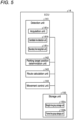
- FIG. 5 is a block diagram showing an example of the functional configuration of the ECU 14 according to the present embodiment.
- the ECU 14 includes a detection unit 141, a parking target position setting unit 142, a route calculation unit 143, a movement control unit 144, and a storage unit 150.
- Each configuration of the detection unit 141, the parking target position setting unit 142, the route calculation unit 143, and the movement control unit 144 shown in FIG. 5 is achieved by the CPU 14a executing a program stored in the ROM 14b. Note that these configurations may be achieved by a hardware circuit.
- the detection unit 141 detects a boundary line in accordance with image data around the vehicle 1 captured by the imaging unit 15.
- the boundary line is, for example, a white line having a width.
- the detection unit 141 stores the data (e.g., position information) of the detected boundary line in the storage unit 150. That is, the detection unit 141 manages the boundary line.
- the detection unit 141 accesses the storage unit 150, refers to the data of the boundary line, and detects the possible parking area around the vehicle 1 based on the boundary line (e.g., with reference to the boundary line).
- the detection unit 141 supplies a detection result to the parking target position setting unit 142.
- the parking target position setting unit 142 determines a target parking area and a parking target position for the vehicle 1 on the basis of the detection result of the detection unit 141 and the like.
- the parking target position setting unit 142 may receive a selection operation by the driver as to which possible parking area will be set as the target parking area.
- the parking target position setting unit 142 receives the selection operation of the driver through an operation signal acquired from the operation unit 14g.
- the route calculation unit 143 calculates a movement route for moving the vehicle 1 from the current position to the parking target position when parking assistance is started. For example, the route calculation unit 143 calculates a guidance route when receiving an instruction to start parking assistance by an operation signal acquired from the operation unit 14g. The route calculation unit 143 outputs the data of the calculated movement route to the storage unit 150.
- the parking target position setting unit 142 and the route calculation unit 143 receive the operation of the driver through the operation signal acquired from the operation unit 14g
- the operation input of the driver is not limited thereto.
- the process described above may be executed by receiving the operation of the driver input from the operation input unit 10.
- the movement control unit 144 executes steering control on the basis of the data of the movement route to move the vehicle 1. Specifically, the movement control unit 144 accesses the storage unit 150, refers to the data of the movement route, and controls the actuator 13a of the steering system 13 according to the position of the vehicle 1 so that the vehicle 1 moves along the movement route. At this time, for example, the vehicle 1 is accelerated or decelerated (braked) according to the operation of the acceleration operation unit 5 or the braking operation unit 6 by the driver. Further, the movement control unit 144 may display a guide on the monitor device 11 or the like to instruct the driver to operate the acceleration operation unit 5 or the braking operation unit 6.
- the storage unit 150 includes, for example, a storage device such as the SSD 14f. In addition, the storage unit 150 stores the data of the boundary line and the data of the movement route in the parking assistance. Specifically, the storage unit 150 includes a straight-line group storage unit 150a and a frame-line group storage unit 150b. The straight-line group storage unit 150a stores straight line data. The frame-line group storage unit 150b stores frame line data.
- the parking assistance As an example of the parking assistance, an example in which automatic steering is executed by the movement control unit 144 and other operations are executed by the driver himself/herself is illustrated, but the parking assistance is not limited thereto.
- the movement control unit 144 may automatically control the operation of the acceleration operation unit 5.
- a configuration in which the movement control unit 144 automatically controls the operation of the shift operation unit 7 may be adopted.
- FIG. 6 is a diagram showing an example of the movement route generated by the ECU (parking assistance device) according to the present embodiment.
- the vehicle 1 images the periphery while traveling in the direction indicated by arrow F.
- the detection unit 141 detects a boundary line 201 on a road surface 200 in the image data captured by the imaging unit 15.
- the parking target position setting unit 142 specifies a parking area M from the detection result of the boundary line 201, and then specifies a parking target position N for parking in the parking area M.
- a center position of a line connecting the left and right rear wheels 3R of the vehicle 1 is set as a reference position G, and a position at which the reference position G reaches is set as a parking target position N.
- a movement route 301 is a route from a position P1 of the vehicle 1 at the time when parking assistance is started to the parking target position N.
- another vehicle 401 is parked adjacent to the boundary line 201.
- FIG. 7 is a diagram showing image data obtained by imaging the road surface 200 according to the embodiment. Specifically, FIG. 7 shows image data when a shadow 501 of another vehicle 401, the shadow 501 of another vehicle 401, is on the road surface 200.
- FIG. 8 is an enlarged view of an edge 501a of the shadow 501 in the image data of FIG. 7 .
- color blurring may occur at the edge of the shadow 501 as shown in FIG. 8 in imaging data obtained by imaging the edge 501a of the shadow 501.
- the following process is performed so as not to erroneously recognize the blurring portion as the boundary line 201.
- FIG. 9 is a view for explaining a determination process executed by the ECU (parking assistance device) according to the embodiment.
- FIG. 10 is a view for explaining a pair of areas in the determination process executed by the ECU (parking assistance device) according to the embodiment.
- FIG. 11 is a view for explaining a road surface on which coating is applied adjacent to a boundary line in the embodiment.
- a candidate line detection unit 141b detects a candidate line Q that is a candidate for the boundary line 201 in the image data acquired by the imaging of the periphery of the vehicle 1.
- the candidate line Q is defined by a pair of straight lines L1, L2.
- the pair of straight lines L1, L2 are lines arranged at parallelism within a prescribed range.
- the candidate line Q is the boundary line 201 in FIG. 6 , and is the edge 501a of the shadow 501 in FIGS. 8 and 9 . That is, the edge 501a is a line (strip-shaped line) defined by the pair of straight lines L1, L2 and having a width with the facing direction of the pair of straight lines L1, L2 as the width direction.
- a boundary line recognition unit 141c sets a pair of areas R1, R2 on both sides in the width direction of the candidate line Q in the image data ( FIG. 9 ).
- the pair of areas R1, R2 is determined on the basis of, for example, the candidate line Q. As shown in FIG. 10 , the pair of areas R1, R2 is line-symmetric with respect to the candidate line Q.
- Each of the pair of areas R1, R2 is set at a prescribed distance from the candidate line Q. The prescribed distance is a distance smaller than the width of the candidate line Q (the width between the straight line L1 and the straight line L2).
- the width of each of the areas R1, R2 is narrower than the width of the candidate line Q.
- the length of each of the areas R1, R2 is shorter than the length of the candidate line Q.
- Each of the areas R1, R2 is set to a size including a plurality of pixels. Note that the shape of each of the areas R1, R2 is not limited to the above.
- the boundary line recognition unit 141c executes a determination process to determine whether or not the difference in luminance between the pair of areas R1, R2 is equal to or larger than a luminance threshold.
- the boundary line recognition unit 141c does not recognize the candidate line Q as the boundary line 201 when determining that the luminance difference is equal to or larger than the luminance threshold, and recognizes the candidate line Q as the boundary line 201 when determining that the luminance difference is less than the luminance threshold.
- the difference in luminance between the pair of areas R1, R2 is, for example, a difference between an average value of luminance of a plurality of pixels in one area R1 and an average value of luminance of a plurality of pixels in the other area R2.
- the luminance search range can be set to the minimum.
- the reason why the pair of areas R1, R2 is separated from the straight lines L1, L2 of the candidate line Q is that the luminance near the straight lines L1, L2 is not stable.
- the boundary line recognition unit 141c recognizes the candidate line Q as the boundary line 201 without executing the determination process. For example, the color blurring width of the edge 501a of the shadow 501 in the image data is narrower than that of the general white line boundary line 201.
- the boundary line recognition unit 141c can recognize the candidate line Q as the boundary line 201 when the width of the candidate line Q exceeds the width threshold even if there is a difference in luminance between both sides of the candidate line Q.
- the boundary line recognition unit 141c recognizes the candidate line Q as the boundary line 201 without executing the determination process.
- the resolution of the pixel of the candidate line Q is, for example, the resolution of the pixel at the end portion of the candidate line Q on the vehicle 1 side. Specifically, the resolution is obtained by [Distance (mm) between respective front ends L11, L21 (two points) of straight lines L1, L2] ⁇ [Pixel distance (pixel) between respective front ends L11, L21 (two points) of straight lines L1, L2].
- the front ends L11, L21 of the straight lines L1, L2 are ends on the vehicle 1 side among both ends of the straight lines L1, L2 expressed in a coordinate system with the current (latest) position of the vehicle 1 as the origin.
- the resolution threshold is, for example, 50 to 80 (mm/pixel). Note that the resolution threshold may be other than the above.
- color blurring due to chromatic aberration easily occurs. In other words, in the image data, color blurring due to chromatic aberration is less likely to occur as the position is closer to the center of the image, that is, as the resolution of the pixel is smaller. Therefore, even if there is a difference in luminance between both sides of the candidate line Q, when the resolution of the pixel in the candidate line Q exceeds the resolution threshold, the boundary line recognition unit 141c can recognize the candidate line Q as the boundary line 201.
- FIG. 12 is a flowchart showing a process of setting a parking target position for the vehicle.
- the detection unit 141 acquires the data of the road surface image captured by the imaging unit 15 (S1), and recognizes (detects) the boundary line in the image data (S2).
- the detection unit 141 supplies the recognition result to the parking target position setting unit 142, stores the data of the boundary line in the storage unit 150, and manages the boundary line (S3).
- the detection unit 141 accesses the storage unit 150, refers to the data of the boundary line, and detects the possible parking area around the vehicle 1 based on the boundary line (e.g., with reference to the boundary line).
- the detection unit 141 supplies a detection result to the parking target position setting unit 142.
- the parking target position setting unit 142 determines a target parking area and a parking target position for the vehicle 1 on the basis of the detection result of the detection unit 141 and the like (S4).
- the route calculation unit 143 calculates a movement route for moving the vehicle 1 from the current position to the parking target position when parking assistance is started.
- the route calculation unit 143 outputs data of the calculated movement route to the storage unit 150 (S5)
- the movement control unit 144 accesses the storage unit 150, refers to the data of the movement route, and executes steering control to move the vehicle 1 so that the vehicle 1 moves along the movement route.
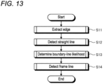
- FIG. 13 is a flowchart showing a boundary line recognition process for the vehicle 1 according to the embodiment.
- the detection unit 141 extracts an edge in the acquired image data (S11), and extracts a straight line in the image data on the basis of the extracted edge (S12).
- the detection unit 141 determines a boundary-line likelihood for the extracted straight line (S13).
- the boundary-line likelihood is based on, for example, the length of a straight line. When the length of the straight line is within a predetermined range, the detection unit 141 determines that the straight line is likely to be a boundary line (likely to be a part of the boundary line).
- the detection unit 141 causes the straight-line group storage unit 150a to store the straight line determined to be likely to be the boundary line (likely to be a part of the boundary line).
- the detection unit 141 detects a frame line (S14).
- the frame line is a pair of straight lines constituting the boundary line. In step S 14, specifically, the detection unit 141 detects a boundary line including a frame line.
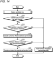
- FIG. 14 is a flowchart showing a frame line detection process for the vehicle according to the embodiment.
- the candidate line detection unit 141b detects the candidate line Q (S21). Specifically, the candidate line detection unit 141b determines a pair (straight line pair) from the straight lines stored in the straight-line group storage unit 150a. The candidate line detection unit 141b determines that two straight lines, having an interval equal to or less than a predetermined interval and having parallelism within a predetermined range, are paired. These two straight lines are frame lines of the candidate lines. That is, the candidate line detection unit 141b detects the candidate line. The candidate line detection unit 141b associates and stores the two straight lines determined to be paired in the frame-line group storage unit 150b. In other words, the candidate line detection unit 141b stores the candidate line in the frame-line group storage unit 150b.
- the boundary line recognition unit 141c determines whether the width of candidate line Q is equal to or less than the width threshold (S22). When the width of the candidate line Q is equal to or less than the width threshold (S22: Yes), the boundary line recognition unit 141c determines whether or not the pixel resolution of the candidate line Q is equal to or larger than the resolution threshold (S23). When the pixel resolution is equal to or larger than the resolution threshold (S23: Yes), the boundary line recognition unit 141c performs the determination process (S24 to S25).
- the boundary line recognition unit 141c calculates a luminance difference that is a difference in luminance between the pair of areas R1, R2 (S24), and determines whether or not the luminance difference is equal to or larger than the luminance threshold (S25). When it is determined that the luminance difference is equal to or larger than the luminance threshold (S25: Yes), the boundary line recognition unit 141c does not recognize the candidate line Q as the boundary line 201, and performs an exclusion process (S26).
- the exclusion process is a process of deleting the paired straight lines (candidate line Q) from the frame-line group storage unit 150b.
- the boundary line recognition unit 141c holds the memory of the paired straight lines (candidate line Q) stored in the frame-line group storage unit 150b (S27). That is, the boundary line recognition unit 141c recognizes the candidate line Q as the boundary line 201.
- the boundary line recognition unit 141c holds the memory of the paired straight lines (candidate line Q) stored in the frame-line group storage unit 150b without executing the determination process in S24 to S25 (S27). That is, the boundary line recognition unit 141c recognizes the candidate line Q as the boundary line 201.
- the ECU 14 (parking assistance device) includes the candidate line detection unit 141b, the boundary line recognition unit 141c, the parking target position setting unit 142, and the movement control unit 144.
- the candidate line detection unit 141b detects the candidate line Q that is a candidate for the boundary line 201 in the image data obtained by imaging the periphery of the vehicle 1.
- the boundary line recognition unit 141c executes a determination process to determine whether or not a difference in luminance between the pair of areas R1, R2 on both sides in the width direction of the candidate line Q in the image data is equal to or larger than a luminance threshold.
- the boundary line recognition unit 141c does not recognize the candidate line Q as the boundary line 201 when determining that the luminance difference is equal to or larger than the luminance threshold, and recognizes the candidate line Q as the boundary line 201 when determining that the luminance difference is less than the luminance threshold.
- the parking target position setting unit 142 sets the parking target position N on the basis of the boundary line 201.
- the movement control unit 144 moves the vehicle 1 to the parking target position N.
- the boundary line recognition unit 141c does not recognize the candidate line Q, that is, the edge of the shadow, as the boundary line 201. Therefore, with the above configuration, the edge 501a of the shadow 501 is suppressed from being erroneously recognized as the boundary line 201, so that it is possible to improve the accuracy in the detection of the boundary line 201.
- the boundary line recognition unit 141c recognizes the candidate line Q as the boundary line 201 without executing the determination process.
- the boundary line recognition unit 141c recognizes the candidate line Q as the boundary line 201. Therefore, with the above configuration, the edge 501a of the shadow 501 is suppressed from being erroneously recognized as the boundary line 201, and the normal boundary line 201 is easily recognized correctly.
- the boundary line recognition unit 141c recognizes the candidate line Q as the boundary line 201 without executing the determination process.
- the boundary line recognition unit 141c recognizes the candidate line Q as the boundary line 201. Therefore, with the above configuration, the edge of the shadow is suppressed from being erroneously recognized as the boundary line 201, and the normal boundary line 201 is easily recognized correctly.
- the difference in luminance between the pair of areas R1, R2 is a difference between an average value of luminance of a plurality of pixels in one area R1 and an average value of luminance of a plurality of pixels in the other area R2.
- the average value of the luminance of the plurality of pixels in the areas R1, R2 is used for determination, so that the luminance of the pair of areas R1, R2 can be compared even if the luminance varies in the areas R1, R2.
- the color system of the image data may be a YUV color system, an HSV color system, an HSL color system, or the like.
Landscapes
- Engineering & Computer Science (AREA)
- Physics & Mathematics (AREA)
- General Physics & Mathematics (AREA)
- Theoretical Computer Science (AREA)
- Computer Vision & Pattern Recognition (AREA)
- Multimedia (AREA)
- Software Systems (AREA)
- Geometry (AREA)
- Automation & Control Theory (AREA)
- Transportation (AREA)
- Mechanical Engineering (AREA)
- Traffic Control Systems (AREA)
- Control Of Driving Devices And Active Controlling Of Vehicle (AREA)
Abstract
Description
- The present embodiment relates to a parking assistance device.
- Conventionally, in a parking assistance device that performs image processing on image data obtained by imaging a periphery of a vehicle, a boundary line on the road surface is detected in the image data in order to set a parking target position.
- Patent Literature 1:
JP 2021-68125 A - However, in the conventional technique described above, in a case where there is a shadow of another vehicle or the like on the road surface, when color blurring occurs at the edge of the shadow in imaging data obtained by imaging the edge of the shadow, the blurring portion is erroneously recognized as a boundary line.
- Therefore, one of the problems to be solved by the embodiment of the present invention is to obtain, for example, a parking assistance device capable of improving the accuracy in detection of a boundary line.
- A parking assistance device according to an embodiment includes: a candidate line detection unit that detects a candidate line that is a candidate for a boundary line in image data obtained by imaging a periphery of a vehicle; a boundary line recognition unit that executes a determination process to determine whether or not a difference in luminance between areas on an outside of the candidate line in a width direction in the image data, the areas being on both sides of the candidate line, is equal to or larger than a luminance threshold, does not recognize the candidate line as a boundary line when determining that the difference in luminance is equal to or larger than the luminance threshold, and recognizes the candidate line as a boundary line when determining that the difference in luminance is less than the luminance threshold; a parking target position setting unit that sets a parking target position on a basis of the boundary line; and a movement control unit that moves the vehicle to the parking target position.
- With such a configuration, for example, even if the candidate line detection unit detects the edge of the shadow as the candidate line in the image data obtained by imaging the edge of the shadow, the boundary line recognition unit does not recognize the candidate line, that is, the edge of the shadow, as a boundary line when the difference in luminance between the pair of areas on both sides of the candidate line is equal to or larger than the luminance threshold. Therefore, with the above configuration, the edge of the shadow is suppressed from being erroneously recognized as a boundary line, so that it is possible to improve the accuracy in detection of a boundary line.
- In the parking assistance device, for example, the boundary line recognition unit executes the determination process when the width of the candidate line does not exceed a width threshold.
- In the parking assistance device, for example, when the width of the candidate line exceeds the width threshold, the boundary line recognition unit recognizes the candidate line as a boundary line without executing the determination process.
- With such a configuration, even if a normal boundary line is detected as a candidate line in image data obtained by imaging the normal boundary line, and there is a difference in luminance between both sides of the candidate line, when the width of the candidate line exceeds the width threshold, the boundary line recognition unit recognizes the candidate line as a boundary line. Therefore, with the above configuration, the edge of the shadow is suppressed from being erroneously recognized as a boundary line, and the normal boundary line is easily recognized correctly.
- The boundary line recognition unit executes the determination process when the resolution of the pixel of the candidate line in the image data does not exceed a resolution threshold.
- In the parking assistance device, for example, when the resolution of a pixel of the candidate line in the image data exceeds the resolution threshold, the boundary line recognition unit recognizes the candidate line as a boundary line without executing the determination process.
- With such a configuration, even if there is a difference in luminance between both sides of the candidate line, when the resolution of the pixel in the candidate line exceeds the resolution threshold, the boundary line recognition unit recognizes the candidate line as a boundary line. Therefore, with the above configuration, the edge of the shadow is suppressed from being erroneously recognized as a boundary line, and the normal boundary line is easily recognized correctly.
- In the parking assistance device, for example, the difference in luminance between the areas on both sides is a difference between an average value of the luminance of a plurality of pixels in one of the areas and an average value of the luminance of a plurality of pixels in the other of the areas.
- With such a configuration, for example, the average value of the luminance of the plurality of pixels in each of the areas is used for determination, so that the luminance of the pair of areas can be compared even if the luminance varies in the area.
- In the parking assistance device, for example, the areas on both sides are located at positions separated from the candidate line by a predetermined distance.
- With such a configuration, for example, the luminance difference is not taken immediately beside the candidate line, but the luminance difference is taken at positions away from the candidate line by a predetermined distance, so that it is possible to suppress the influence of color blurring at the edge of the shadow.
-
-
FIG. 1 is an exemplary perspective view showing a state where a part of a vehicle interior of a vehicle, to which an electronic control unit (ECU) (parking assistance device) according to an embodiment is applied, is in perspective. -
FIG. 2 is an exemplary plan view (overhead view) of the vehicle to which the ECU according to the embodiment is applied. -
FIG. 3 is a view of an example of the dashboard of the vehicle to which the ECU according to the embodiment is applied, as viewed from the rear of the vehicle. -
FIG. 4 is a diagram showing an example of a hardware configuration of a vehicle control system including the ECU (parking assistance device) according to the embodiment. -
FIG. 5 is a block diagram showing an example of the functional configuration of the ECU (parking assistance device) according to the embodiment. -
FIG. 6 is a diagram showing an example of a movement route generated by the ECU (parking assistance device) according to the embodiment. -
FIG. 7 is a diagram showing image data obtained by imaging the road surface according to the embodiment. -
FIG. 8 is an enlarged view showing an edge of a shadow in the image data ofFIG. 7 . -
FIG. 9 is a view for explaining a determination process executed by the ECU (parking assistance device) according to the embodiment. -
FIG. 10 is a view for explaining a pair of areas in the determination process executed by the ECU (parking assistance device) according to the embodiment. -
FIG. 11 is a view for explaining a road surface on which coating is applied adjacent to a boundary line in the embodiment. -
FIG. 12 is a flowchart showing a process of setting a parking target position for a vehicle in the embodiment. -
FIG. 13 is a flowchart showing a boundary line recognition process for a vehicle according to the embodiment. -
FIG. 14 is a flowchart showing a frame line detection process for the vehicle according to the embodiment. - Hereinafter, a parking assistance device of the present embodiment can be an on-board electronic control unit (ECU) and mounted on a vehicle. The vehicle on which the parking assistance device is mounted may be, for example, a
vehicle 1 as shown inFIGS. 1 and 2. FIG. 1 is an exemplary perspective view showing a state where a part of a vehicle interior 2a of thevehicle 1, to which an ECU (parking assistance device) according to the embodiment, is applied.FIG. 2 is an exemplary plan view (overhead view) of thevehicle 1 to which the ECU according to the embodiment is applied. In the present embodiment, thevehicle 1 on which a vehicle control device is mounted may be, for example, an automobile having an internal combustion engine (not shown) as a drive source, that is, an internal combustion engine automobile, or may be an automobile having an electric motor (not shown) as a drive source, that is, an electric automobile, a fuel cell automobile, or the like. Alternatively, thevehicle 1 may be a hybrid automobile using both an internal combustion engine and an electric motor as a drive sources, or may be a car including another drive source. In thevehicle 1, various transmission devices can be mounted, and various devices necessary for driving the internal combustion engine and the electric motor can be mounted, for example, systems, components, and the like. - As shown in
FIG. 1 , thevehicle body 2 constitutes avehicle interior 2a in which an occupant (not shown) rides. In thevehicle interior 2a, asteering unit 4, anacceleration operation unit 5, abraking operation unit 6, ashift operation unit 7, and the like are provided in a state of facing aseat 2b of a driver as an occupant. Thesteering unit 4 is, for example, a steering wheel protruding from thedashboard 24, theacceleration operation unit 5 is, for example, an accelerator pedal located under the feet of the driver, thebraking operation unit 6 is, for example, a brake pedal located under the feet of the driver, and theshift operation unit 7 is, for example, a shift lever protruding from a center console. Note that thesteering unit 4, theacceleration operation unit 5, thebraking operation unit 6, theshift operation unit 7, and the like are not limited thereto. - In the
vehicle interior 2a, adisplay device 8 as a display output unit and anaudio output device 9 as an audio output unit are provided. Thedisplay device 8 is, for example, a liquid crystal display (LCD), an organic electroluminescent display (OELD), or the like. Theaudio output device 9 is, for example, a speaker. Thedisplay device 8 is covered with a transparentoperation input unit 10 such as a touch panel. The occupant can visually recognize an image displayed on the display screen of thedisplay device 8 via theoperation input unit 10. In addition, the occupant can perform an operation input by using his or her finger or the like to touch, push, or move across theoperation input unit 10 at a position corresponding to an image displayed on the display screen of thedisplay device 8. Thedisplay device 8, theaudio output device 9, theoperation input unit 10, and the like are provided, for example, in amonitor device 11 located at the center of thedashboard 24 in the vehicle width direction, that is, the left-right direction. Themonitor device 11 can include an operation input unit (not shown) such as a switch, a dial, a joystick, and a push button. In addition, an audio output device (not shown) can be provided at another position in thevehicle interior 2a different from themonitor device 11, and audio can be output from theaudio output device 9 of themonitor device 11 and another audio output device. Note that themonitor device 11 can also be used as, for example, a navigation system or an audio system. -
FIG. 3 is a view of an example of the dashboard of thevehicle 1 to which the ECU according to the embodiment is applied, as viewed from the rear of the vehicle. As shown inFIG. 3 , adisplay device 12 different from thedisplay device 8 is provided in thevehicle interior 2a. For example, thedisplay device 12 is provided, for example, on aninstrument panel 25 of thedashboard 24, and is located between aspeed indicator 25a and arotation number indicator 25b substantially at the center of theinstrument panel 25. The size of thescreen 12a of thedisplay device 12 is smaller than the size of the screen 8a of thedisplay device 8. Thedisplay device 12 can mainly display an image indicating information on parking assistance for thevehicle 1. The amount of information displayed on thedisplay device 12 may be smaller than the amount of information displayed on thedisplay device 8. Thedisplay device 12 is, for example, an LCD, an OELD, or the like. Note that information displayed on thedisplay device 12 may be displayed on thedisplay device 8. - As shown in
FIGS. 1 and 2 , thevehicle 1 is, for example, a four-wheeled automobile, and includes two left and rightfront wheels 3F and two left and rightrear wheels 3R. All of these fourwheels 3 can be configured to be steerable. Thevehicle 1 includes a steering system 13 (FIG. 4 ) that steers at least twowheels 3. Thesteering system 13 includes anactuator 13a and atorque sensor 13b. Thesteering system 13 is electrically controlled by an electronic control unit (ECU) 14 or the like to operate theactuator 13a. Thesteering system 13 is, for example, an electric power steering system, a steer by wire (SBW) system, or the like. In thesteering system 13, torque, that is, assist torque, is applied to thesteering unit 4 by theactuator 13a to supplement the steering force, and thewheel 3 is steered by theactuator 13a. In this case, theactuator 13a may steer onewheel 3 or may steer a plurality ofwheels 3. Thetorque sensor 13b detects, for example, torque applied to thesteering unit 4 by the driver. - As shown in
FIG. 2 , thevehicle body 2 is provided with, for example, fourimaging units 15a to 15d as a plurality ofimaging units 15. Theimaging unit 15 is, for example, a digital camera incorporating an imaging element such as a charge-coupled device (CCD) or a complementary metal-oxide-semiconductor (CMOS) image sensor (CIS). Theimaging unit 15 can output moving image data at a predetermined frame rate. Each of theimaging units 15 includes a wide-angle lens or a fisheye lens, and can capture a range of, for example, 140° to 190° in the horizontal direction. The optical axis of theimaging unit 15 is set obliquely downward. Therefore, theimaging unit 15 sequentially captures an external environment around thevehicle body 2 including the road surface on which thevehicle 1 can move and an area where thevehicle 1 can be parked, and outputs the captured environment as captured image data. - The
imaging unit 15a is located, for example, at anend 2e on the rear side of thevehicle body 2, and is provided in a wall portion below adoor 2h of a rear trunk. Theimaging unit 15b is located, for example, at anend 2f on the right side of thevehicle body 2 and is provided on theright door mirror 2g. Theimaging unit 15c is located, for example, at anend 2c on the front side of thevehicle body 2, that is, on the front side in the vehicle front-rear direction, and is provided on a front bumper or the like. Theimaging unit 15d is located, for example, at anend 2d on the left side of thevehicle body 2, that is, on the left side in the vehicle width direction, and is provided on thedoor mirror 2g as a left protruding portion. TheECU 14 can execute computational processing and image processing on the basis of image data obtained by the plurality ofimaging units 15 to generate an image with a wider viewing angle or generate a virtual overhead image of thevehicle 1 viewed from above. Note that the overhead image may also be referred to as a planar image. - Further, the
ECU 14 performs image processing on the image captured by theimaging unit 15, and detects a boundary line indicated on the road surface aroundvehicle 1. TheECU 14 detects a parking target position (e.g., possible parking area, etc.) for thevehicle 1 based on the detected boundary line. - As shown in
FIGS. 1 and 2 , thevehicle body 2 is provided with, for example, fourdistance measurement units 16a to 16d and eightdistance measurement units 17a to 17h as a plurality ofdistance measurement units distance measurement units ECU 14 can measure the presence or absence of an object, such as an obstacle located around thevehicle 1, and the distance to the object from detection results of thedistance measurement units distance measurement units distance measurement unit 17 can be used, for example, to detect an object at a relatively short distance, and thedistance measurement unit 16 can be used, for example, to detect an object at a relatively long distance, beyond the range of thedistance measurement unit 17. Thedistance measurement unit 17 can be used, for example, to detect objects in the front and rear of thevehicle 1, and thedistance measurement unit 16 can be used to detect an object to the side of thevehicle 1. -
FIG. 4 is a diagram showing an example of a hardware configuration of a vehicle control system including the ECU (parking assistance device) according to the embodiment. As shown inFIG. 4 , in thevehicle control system 100, in addition to theECU 14, themonitor device 11, thesteering system 13, thedistance measurement units brake system 18, asteering angle sensor 19, anaccelerator sensor 20, ashift sensor 21, awheel speed sensor 22, and the like are electrically connected via an in-vehicle network 23 as an electric communication line. The in-vehicle network 23 is configured as, for example, a controller area network (CAN). TheECU 14 can control thesteering system 13, thebrake system 18, and the like by sending a control signal through the in-vehicle network 23. Further, theECU 14 can receive detection results of thetorque sensor 13b, thebrake sensor 18b, thesteering angle sensor 19, thedistance measurement unit 16, thedistance measurement unit 17, theaccelerator sensor 20, theshift sensor 21, thewheel speed sensor 22, and the like, operation signals of theoperation input unit 10 and the like via the in-vehicle network 23. - The
ECU 14 includes, for example, a central processing unit (CPU) 14a, a read-only memory (ROM) 14b, a random-access memory (RAM) 14c, adisplay control unit 14d, an audio control unit 14e, a solid-state drive (SSD, flash memory) 14f, and the like. TheCPU 14a can execute various types of computational processing and control, such as image processing related to images displayed on thedisplay devices vehicle 1, calculating a movement route of thevehicle 1, determining the presence or absence of interference with an object, automatically controlling thevehicle 1, and canceling the automatic control. TheCPU 14a can read a program installed and stored in a nonvolatile storage device such as theROM 14b and execute computational processing according to the program. TheRAM 14c temporarily stores various data used in the calculation in theCPU 14a. Thedisplay control unit 14d mainly executes image processing using image data obtained by theimaging unit 15, composition of image data displayed on thedisplay device 8, and the like, among the computational processing in theECU 14. The audio control unit 14e mainly executes processing for audio data output by theaudio output device 9 among the computational processing in theECU 14. TheSSD 14f is a rewritable nonvolatile storage unit, and can store data even if the power supply of theECU 14 is turned off. Note that theCPU 14a, theROM 14b, theRAM 14c, and the like can be integrated in the same package. TheECU 14 may have a configuration in which, instead of theCPU 14a, another logical operation processor such as a digital signal processor (DSP), a logic circuit, or the like is used. Further, a hard disk drive (HDD) may be provided instead of theSSD 14f, and theSSD 14f and the HDD may be provided separately from theECU 14. TheECU 14 is an example of a parking assistance device. - The
brake system 18 is, for example, an anti-lock brake system (ABS) that suppresses locking of a brake, an electronic stability control (ESC) that suppresses skidding of thevehicle 1 at the time of cornering, an electric brake system that enhances braking force (executes brake assist), a brake by wire (BBW), or the like. Thebrake system 18 applies braking force to thewheel 3 and thus thevehicle 1 via theactuator 18a. In addition, thebrake system 18 can execute various controls by detecting brake lock-up, idle rotation of thewheel 3, a sign of skidding, or the like from the difference in the rotations of the left andright wheels 3, or the like. Thebrake sensor 18b is, for example, a sensor that detects the position of the movable portion of thebraking operation unit 6. Thebrake sensor 18b can detect the position of the brake pedal as the movable portion. Thebrake sensor 18b includes a displacement sensor. - The
steering angle sensor 19 is, for example, a sensor that detects the amount of steering of thesteering unit 4 such as a steering wheel. Thesteering angle sensor 19 is configured using, for example, a Hall element or the like. TheECU 14 acquires the amount of steering of thesteering unit 4 by the driver, the amount of steering of eachwheel 3 at the time of automatic steering, and the like from thesteering angle sensor 19 and executes various controls. Note that thesteering angle sensor 19 detects the rotation angle of the rotating portion included in thesteering unit 4. Thesteering angle sensor 19 is an example of an angle sensor. - The
accelerator sensor 20 is, for example, a sensor that detects the position of the movable portion of theacceleration operation unit 5. Theaccelerator sensor 20 can detect the position of the accelerator pedal as the movable portion. Theaccelerator sensor 20 includes a displacement sensor. - The
shift sensor 21 is, for example, a sensor that detects the position of the movable portion of theshift operation unit 7. Theshift sensor 21 can detect positions of a lever, an arm, a button, and the like as the movable portion. Theshift sensor 21 may include a displacement sensor or may be configured as a switch. - The
wheel speed sensor 22 is a sensor that detects the amount of rotation of thewheel 3 and the number of rotations per unit time. Thewheel speed sensor 22 outputs the number of wheel speed pulses indicating the detected number of rotations as a sensor value. Thewheel speed sensor 22 can be configured using, for example, a Hall element or the like. TheECU 14 calculates the amount of movement and the like of thevehicle 1 on the basis of the sensor value acquired from thewheel speed sensor 22 and executes various controls. Note that thewheel speed sensor 22 may be provided in thebrake system 18. In this case, theECU 14 acquires the detection result of thewheel speed sensor 22 via thebrake system 18. - Note that the configurations, arrangements, electrical connection forms, and the like of the various sensors and actuators described above are merely examples, and can be set (changed) in various ways.
-
FIG. 5 is a block diagram showing an example of the functional configuration of theECU 14 according to the present embodiment. As shown inFIG. 5 , theECU 14 includes a detection unit 141, a parking targetposition setting unit 142, a route calculation unit 143, a movement control unit 144, and astorage unit 150. - Each configuration of the detection unit 141, the parking target
position setting unit 142, the route calculation unit 143, and the movement control unit 144 shown inFIG. 5 is achieved by theCPU 14a executing a program stored in theROM 14b. Note that these configurations may be achieved by a hardware circuit. - The detection unit 141 detects a boundary line in accordance with image data around the
vehicle 1 captured by theimaging unit 15. The boundary line is, for example, a white line having a width. The detection unit 141 stores the data (e.g., position information) of the detected boundary line in thestorage unit 150. That is, the detection unit 141 manages the boundary line. The detection unit 141 accesses thestorage unit 150, refers to the data of the boundary line, and detects the possible parking area around thevehicle 1 based on the boundary line (e.g., with reference to the boundary line). The detection unit 141 supplies a detection result to the parking targetposition setting unit 142. - The parking target
position setting unit 142 determines a target parking area and a parking target position for thevehicle 1 on the basis of the detection result of the detection unit 141 and the like. When the detection unit 141 detects a plurality of possible parking areas, the parking targetposition setting unit 142 may receive a selection operation by the driver as to which possible parking area will be set as the target parking area. For example, the parking targetposition setting unit 142 receives the selection operation of the driver through an operation signal acquired from theoperation unit 14g. - The route calculation unit 143 calculates a movement route for moving the
vehicle 1 from the current position to the parking target position when parking assistance is started. For example, the route calculation unit 143 calculates a guidance route when receiving an instruction to start parking assistance by an operation signal acquired from theoperation unit 14g. The route calculation unit 143 outputs the data of the calculated movement route to thestorage unit 150. - Although the parking target
position setting unit 142 and the route calculation unit 143 receive the operation of the driver through the operation signal acquired from theoperation unit 14g, the operation input of the driver is not limited thereto. For example, the process described above may be executed by receiving the operation of the driver input from theoperation input unit 10. - The movement control unit 144 executes steering control on the basis of the data of the movement route to move the
vehicle 1. Specifically, the movement control unit 144 accesses thestorage unit 150, refers to the data of the movement route, and controls theactuator 13a of thesteering system 13 according to the position of thevehicle 1 so that thevehicle 1 moves along the movement route. At this time, for example, thevehicle 1 is accelerated or decelerated (braked) according to the operation of theacceleration operation unit 5 or thebraking operation unit 6 by the driver. Further, the movement control unit 144 may display a guide on themonitor device 11 or the like to instruct the driver to operate theacceleration operation unit 5 or thebraking operation unit 6. - The
storage unit 150 includes, for example, a storage device such as theSSD 14f. In addition, thestorage unit 150 stores the data of the boundary line and the data of the movement route in the parking assistance. Specifically, thestorage unit 150 includes a straight-linegroup storage unit 150a and a frame-linegroup storage unit 150b. The straight-linegroup storage unit 150a stores straight line data. The frame-linegroup storage unit 150b stores frame line data. - As an example of the parking assistance, an example in which automatic steering is executed by the movement control unit 144 and other operations are executed by the driver himself/herself is illustrated, but the parking assistance is not limited thereto. For example, in addition to steering, the movement control unit 144 may automatically control the operation of the
acceleration operation unit 5. In addition, a configuration in which the movement control unit 144 automatically controls the operation of theshift operation unit 7 may be adopted. -
FIG. 6 is a diagram showing an example of the movement route generated by the ECU (parking assistance device) according to the present embodiment. In the example ofFIG. 6 , thevehicle 1 images the periphery while traveling in the direction indicated by arrow F. The detection unit 141 detects aboundary line 201 on aroad surface 200 in the image data captured by theimaging unit 15. Then, the parking targetposition setting unit 142 specifies a parking area M from the detection result of theboundary line 201, and then specifies a parking target position N for parking in the parking area M. In the present embodiment, for example, a center position of a line connecting the left and rightrear wheels 3R of thevehicle 1 is set as a reference position G, and a position at which the reference position G reaches is set as a parking target position N. Amovement route 301 is a route from a position P1 of thevehicle 1 at the time when parking assistance is started to the parking target position N. In the example ofFIG. 6 , anothervehicle 401 is parked adjacent to theboundary line 201. -
FIG. 7 is a diagram showing image data obtained by imaging theroad surface 200 according to the embodiment. Specifically,FIG. 7 shows image data when ashadow 501 of anothervehicle 401, theshadow 501 of anothervehicle 401, is on theroad surface 200.FIG. 8 is an enlarged view of anedge 501a of theshadow 501 in the image data ofFIG. 7 . - As shown in
FIG. 7 , for example, when theshadow 501 of anothervehicle 401 is on theroad surface 200, color blurring may occur at the edge of theshadow 501 as shown inFIG. 8 in imaging data obtained by imaging theedge 501a of theshadow 501. In such a case, in the present embodiment, the following process is performed so as not to erroneously recognize the blurring portion as theboundary line 201. -
FIG. 9 is a view for explaining a determination process executed by the ECU (parking assistance device) according to the embodiment.FIG. 10 is a view for explaining a pair of areas in the determination process executed by the ECU (parking assistance device) according to the embodiment.FIG. 11 is a view for explaining a road surface on which coating is applied adjacent to a boundary line in the embodiment. - A candidate
line detection unit 141b detects a candidate line Q that is a candidate for theboundary line 201 in the image data acquired by the imaging of the periphery of thevehicle 1. As shown inFIGS. 6 ,8, and 9 , the candidate line Q is defined by a pair of straight lines L1, L2. The pair of straight lines L1, L2 are lines arranged at parallelism within a prescribed range. The candidate line Q is theboundary line 201 inFIG. 6 , and is theedge 501a of theshadow 501 inFIGS. 8 and 9 . That is, theedge 501a is a line (strip-shaped line) defined by the pair of straight lines L1, L2 and having a width with the facing direction of the pair of straight lines L1, L2 as the width direction. - A boundary line recognition unit 141c sets a pair of areas R1, R2 on both sides in the width direction of the candidate line Q in the image data (
FIG. 9 ). The pair of areas R1, R2 is determined on the basis of, for example, the candidate line Q. As shown inFIG. 10 , the pair of areas R1, R2 is line-symmetric with respect to the candidate line Q. Each of the pair of areas R1, R2 is set at a prescribed distance from the candidate line Q. The prescribed distance is a distance smaller than the width of the candidate line Q (the width between the straight line L1 and the straight line L2). The width of each of the areas R1, R2 is narrower than the width of the candidate line Q. The length of each of the areas R1, R2 is shorter than the length of the candidate line Q. Each of the areas R1, R2 is set to a size including a plurality of pixels. Note that the shape of each of the areas R1, R2 is not limited to the above. - The boundary line recognition unit 141c executes a determination process to determine whether or not the difference in luminance between the pair of areas R1, R2 is equal to or larger than a luminance threshold. The boundary line recognition unit 141c does not recognize the candidate line Q as the
boundary line 201 when determining that the luminance difference is equal to or larger than the luminance threshold, and recognizes the candidate line Q as theboundary line 201 when determining that the luminance difference is less than the luminance threshold. The difference in luminance between the pair of areas R1, R2 is, for example, a difference between an average value of luminance of a plurality of pixels in one area R1 and an average value of luminance of a plurality of pixels in the other area R2. By using the pair of areas R1, R2 in this manner, the luminance search range can be set to the minimum. The reason why the pair of areas R1, R2 is separated from the straight lines L1, L2 of the candidate line Q is that the luminance near the straight lines L1, L2 is not stable. - Here, as shown in
FIG. 11 , when a coating 601 (filling) is applied to the parking slot adjacent to theboundary line 201 on theroad surface 200, the luminance of the portion of thecoating 601 tends to be small. Thus, even if the candidate line Q is anormal boundary line 201, there is a possibility that the luminance difference between the pair of areas R1, R2 on both sides thereof becomes equal to or larger than the luminance threshold. Therefore, when the width of the candidate line Q exceeds the width threshold, the boundary line recognition unit 141c recognizes the candidate line Q as theboundary line 201 without executing the determination process. For example, the color blurring width of theedge 501a of theshadow 501 in the image data is narrower than that of the general whiteline boundary line 201. Therefore, by setting the width threshold to be larger than the width of the blurring and smaller than the width of thepredetermined boundary line 201, the boundary line recognition unit 141c can recognize the candidate line Q as theboundary line 201 when the width of the candidate line Q exceeds the width threshold even if there is a difference in luminance between both sides of the candidate line Q. - When the resolution of the pixel of the candidate line Q in the image data exceeds the resolution threshold, the boundary line recognition unit 141c recognizes the candidate line Q as the
boundary line 201 without executing the determination process. The resolution of the pixel of the candidate line Q is, for example, the resolution of the pixel at the end portion of the candidate line Q on thevehicle 1 side. Specifically, the resolution is obtained by [Distance (mm) between respective front ends L11, L21 (two points) of straight lines L1, L2] ÷ [Pixel distance (pixel) between respective front ends L11, L21 (two points) of straight lines L1, L2]. The front ends L11, L21 of the straight lines L1, L2 are ends on thevehicle 1 side among both ends of the straight lines L1, L2 expressed in a coordinate system with the current (latest) position of thevehicle 1 as the origin. The resolution threshold is, for example, 50 to 80 (mm/pixel). Note that the resolution threshold may be other than the above. In the image data, as the distance from the image center increases, that is, as the resolution of the pixel increases, color blurring due to chromatic aberration easily occurs. In other words, in the image data, color blurring due to chromatic aberration is less likely to occur as the position is closer to the center of the image, that is, as the resolution of the pixel is smaller. Therefore, even if there is a difference in luminance between both sides of the candidate line Q, when the resolution of the pixel in the candidate line Q exceeds the resolution threshold, the boundary line recognition unit 141c can recognize the candidate line Q as theboundary line 201. - Next, a process of setting the parking target position for the vehicle will be described with reference to
FIG. 12. FIG. 12 is a flowchart showing a process of setting a parking target position for the vehicle. - In
ECU 14, the detection unit 141 acquires the data of the road surface image captured by the imaging unit 15 (S1), and recognizes (detects) the boundary line in the image data (S2). The detection unit 141 supplies the recognition result to the parking targetposition setting unit 142, stores the data of the boundary line in thestorage unit 150, and manages the boundary line (S3). The detection unit 141 accesses thestorage unit 150, refers to the data of the boundary line, and detects the possible parking area around thevehicle 1 based on the boundary line (e.g., with reference to the boundary line). The detection unit 141 supplies a detection result to the parking targetposition setting unit 142. The parking targetposition setting unit 142 determines a target parking area and a parking target position for thevehicle 1 on the basis of the detection result of the detection unit 141 and the like (S4). The route calculation unit 143 calculates a movement route for moving thevehicle 1 from the current position to the parking target position when parking assistance is started. The route calculation unit 143 outputs data of the calculated movement route to the storage unit 150 (S5) The movement control unit 144 accesses thestorage unit 150, refers to the data of the movement route, and executes steering control to move thevehicle 1 so that thevehicle 1 moves along the movement route. - Next, details of the boundary line recognition process (S2) will be described with reference to
FIG. 13. FIG. 13 is a flowchart showing a boundary line recognition process for thevehicle 1 according to the embodiment. - The detection unit 141 extracts an edge in the acquired image data (S11), and extracts a straight line in the image data on the basis of the extracted edge (S12). The detection unit 141 determines a boundary-line likelihood for the extracted straight line (S13). The boundary-line likelihood is based on, for example, the length of a straight line. When the length of the straight line is within a predetermined range, the detection unit 141 determines that the straight line is likely to be a boundary line (likely to be a part of the boundary line). The detection unit 141 causes the straight-line
group storage unit 150a to store the straight line determined to be likely to be the boundary line (likely to be a part of the boundary line). Next, the detection unit 141 detects a frame line (S14). The frame line is a pair of straight lines constituting the boundary line. Instep S 14, specifically, the detection unit 141 detects a boundary line including a frame line. - Next, details of the frame line detection process (S14) will be described with reference to
FIG. 14. FIG. 14 is a flowchart showing a frame line detection process for the vehicle according to the embodiment. - The candidate
line detection unit 141b detects the candidate line Q (S21). Specifically, the candidateline detection unit 141b determines a pair (straight line pair) from the straight lines stored in the straight-linegroup storage unit 150a. The candidateline detection unit 141b determines that two straight lines, having an interval equal to or less than a predetermined interval and having parallelism within a predetermined range, are paired. These two straight lines are frame lines of the candidate lines. That is, the candidateline detection unit 141b detects the candidate line. The candidateline detection unit 141b associates and stores the two straight lines determined to be paired in the frame-linegroup storage unit 150b. In other words, the candidateline detection unit 141b stores the candidate line in the frame-linegroup storage unit 150b. - Next, the boundary line recognition unit 141c determines whether the width of candidate line Q is equal to or less than the width threshold (S22). When the width of the candidate line Q is equal to or less than the width threshold (S22: Yes), the boundary line recognition unit 141c determines whether or not the pixel resolution of the candidate line Q is equal to or larger than the resolution threshold (S23). When the pixel resolution is equal to or larger than the resolution threshold (S23: Yes), the boundary line recognition unit 141c performs the determination process (S24 to S25). Specifically, the boundary line recognition unit 141c calculates a luminance difference that is a difference in luminance between the pair of areas R1, R2 (S24), and determines whether or not the luminance difference is equal to or larger than the luminance threshold (S25). When it is determined that the luminance difference is equal to or larger than the luminance threshold (S25: Yes), the boundary line recognition unit 141c does not recognize the candidate line Q as the
boundary line 201, and performs an exclusion process (S26). The exclusion process is a process of deleting the paired straight lines (candidate line Q) from the frame-linegroup storage unit 150b. - On the other hand, when determining that the luminance difference is less than the luminance threshold in S25 (S25: No), the boundary line recognition unit 141c holds the memory of the paired straight lines (candidate line Q) stored in the frame-line
group storage unit 150b (S27). That is, the boundary line recognition unit 141c recognizes the candidate line Q as theboundary line 201. - In either case where the width of the candidate line Q exceeds the width threshold (S22: No) or where the pixel resolution is equal to or larger than the resolution threshold (S23: No), the boundary line recognition unit 141c holds the memory of the paired straight lines (candidate line Q) stored in the frame-line
group storage unit 150b without executing the determination process in S24 to S25 (S27). That is, the boundary line recognition unit 141c recognizes the candidate line Q as theboundary line 201. - As described above, in the present embodiment, the ECU 14 (parking assistance device) includes the candidate
line detection unit 141b, the boundary line recognition unit 141c, the parking targetposition setting unit 142, and the movement control unit 144. The candidateline detection unit 141b detects the candidate line Q that is a candidate for theboundary line 201 in the image data obtained by imaging the periphery of thevehicle 1. The boundary line recognition unit 141c executes a determination process to determine whether or not a difference in luminance between the pair of areas R1, R2 on both sides in the width direction of the candidate line Q in the image data is equal to or larger than a luminance threshold. The boundary line recognition unit 141c does not recognize the candidate line Q as theboundary line 201 when determining that the luminance difference is equal to or larger than the luminance threshold, and recognizes the candidate line Q as theboundary line 201 when determining that the luminance difference is less than the luminance threshold. The parking targetposition setting unit 142 sets the parking target position N on the basis of theboundary line 201. The movement control unit 144 moves thevehicle 1 to the parking target position N. - With such a configuration, for example, even if the candidate
line detection unit 141b detects theedge 501a of theshadow 501 as the candidate line Q in the image data obtained by imaging theedge 501a of theshadow 501, when a difference in luminance between the pair of areas R1, R2 on both sides of the candidate line Q is equal to or larger than the luminance threshold, the boundary line recognition unit 141c does not recognize the candidate line Q, that is, the edge of the shadow, as theboundary line 201. Therefore, with the above configuration, theedge 501a of theshadow 501 is suppressed from being erroneously recognized as theboundary line 201, so that it is possible to improve the accuracy in the detection of theboundary line 201. - When the width of the candidate line Q exceeds the width threshold, the boundary line recognition unit 141c recognizes the candidate line Q as the
boundary line 201 without executing the determination process. - With such a configuration, even if the
normal boundary line 201 is detected as the candidate line Q in the image data obtained by imaging thenormal boundary line 201, and there is a difference in luminance between both sides of the candidate line Q, when the width of the candidate line Q exceeds the width threshold, the boundary line recognition unit 141c recognizes the candidate line Q as theboundary line 201. Therefore, with the above configuration, theedge 501a of theshadow 501 is suppressed from being erroneously recognized as theboundary line 201, and thenormal boundary line 201 is easily recognized correctly. - When the resolution of the pixel of the candidate line Q in the image data exceeds the resolution threshold, the boundary line recognition unit 141c recognizes the candidate line Q as the
boundary line 201 without executing the determination process. - With such a configuration, even if there is a difference in luminance between both sides of the candidate line Q, when the resolution of the pixel in the candidate line Q exceeds the resolution threshold, the boundary line recognition unit 141c recognizes the candidate line Q as the
boundary line 201. Therefore, with the above configuration, the edge of the shadow is suppressed from being erroneously recognized as theboundary line 201, and thenormal boundary line 201 is easily recognized correctly. - The difference in luminance between the pair of areas R1, R2 is a difference between an average value of luminance of a plurality of pixels in one area R1 and an average value of luminance of a plurality of pixels in the other area R2.
- With such a configuration, for example, the average value of the luminance of the plurality of pixels in the areas R1, R2 is used for determination, so that the luminance of the pair of areas R1, R2 can be compared even if the luminance varies in the areas R1, R2.
- Note that, in the present embodiment, an example of the RGB color system is shown as the color system of the image data, but the present invention is not limited thereto. For example, the color system of the image data may be a YUV color system, an HSV color system, an HSL color system, or the like.
- Although the embodiments of the present invention have been exemplified above, the above embodiments are merely examples, and are not intended to limit the scope of the invention. The embodiments can be implemented in various other forms, and various omissions, substitutions, combinations, and changes can be made without departing from the gist of the invention. In addition, the configuration and shape of each example can be partially interchanged. In addition, specifications (structure, type, direction, shape, size, length, width, height, number, arrangement, position, etc.) of each configuration, shape, and the like can be appropriately changed and implemented.
- 1: Vehicle, 14: ECU (parking assistance device), 141b: Candidate line detection unit, 141c: Boundary line recognition unit, 142: Parking target position setting unit, 144: Movement control unit, 201: Boundary line, N: Parking target position, and Q: Candidate line
Claims (5)
- A parking assistance device comprising:a candidate line detection unit that detects a candidate line that is a candidate for a boundary line in image data obtained by imaging a periphery of a vehicle;a boundary line recognition unit that executes a determination process to determine whether or not a difference in luminance between areas on an outside of the candidate line in a width direction in the image data, the areas being on both sides of the candidate line, is equal to or larger than a luminance threshold, does not recognize the candidate line as a boundary line when determining that the difference in luminance is equal to or larger than the luminance threshold, and recognizes the candidate line as a boundary line when determining that the difference in luminance is less than the luminance threshold;a parking target position setting unit that sets a parking target position on a basis of the boundary line; anda movement control unit that moves the vehicle to the parking target position.
- The parking assistance device according to claim 1, wherein the boundary line recognition unit executes the determination process when a width of the candidate line does not exceed a width threshold.
- The parking assistance device according to claim 1 or 2, wherein the boundary line recognition unit executes the determination process when a resolution of the pixel of the candidate line in the image data does not exceed a resolution threshold.
- The parking assistance device according to any one of claims 1 to 3, wherein a difference in luminance between the areas on both sides is a difference between an average value of the luminance of a plurality of pixels in one of the areas and an average value of the luminance of a plurality of pixels in the other of the areas.
- The parking assistance device according to any one of claims 1 to 4, wherein the areas on both sides are located at positions separated from the candidate line by a predetermined distance.
Applications Claiming Priority (2)
| Application Number | Priority Date | Filing Date | Title |
|---|---|---|---|
| JP2021185915A JP7501500B2 (en) | 2021-11-15 | 2021-11-15 | Parking Assistance Device |
| PCT/JP2022/041352 WO2023085228A1 (en) | 2021-11-15 | 2022-11-07 | Parking assistance device |
Publications (2)
| Publication Number | Publication Date |
|---|---|
| EP4434821A1 true EP4434821A1 (en) | 2024-09-25 |
| EP4434821A4 EP4434821A4 (en) | 2025-03-05 |
Family
ID=86336048
Family Applications (1)
| Application Number | Title | Priority Date | Filing Date |
|---|---|---|---|
| EP22892727.3A Pending EP4434821A4 (en) | 2021-11-15 | 2022-11-07 | Parking assistance device |
Country Status (5)
| Country | Link |
|---|---|
| US (1) | US12488599B2 (en) |
| EP (1) | EP4434821A4 (en) |
| JP (1) | JP7501500B2 (en) |
| CN (1) | CN118076518A (en) |
| WO (1) | WO2023085228A1 (en) |
Families Citing this family (2)
| Publication number | Priority date | Publication date | Assignee | Title |
|---|---|---|---|---|
| JP2023148817A (en) * | 2022-03-30 | 2023-10-13 | パナソニックIpマネジメント株式会社 | Parking assistance system and parking assistance method |
| CN121170761A (en) * | 2025-10-24 | 2025-12-19 | 知行汽车科技(苏州)股份有限公司 | Parking space fuzzy attribute determination method, device and equipment |
Family Cites Families (7)
| Publication number | Priority date | Publication date | Assignee | Title |
|---|---|---|---|---|
| JP4692613B2 (en) | 2008-11-28 | 2011-06-01 | トヨタ自動車株式会社 | In-vehicle device and method used in the device |
| JP5847471B2 (en) | 2011-07-20 | 2016-01-20 | キヤノン株式会社 | Image processing apparatus, imaging apparatus, image processing method, and image processing program |
| JP6483446B2 (en) | 2015-01-15 | 2019-03-13 | トヨタ自動車株式会社 | Composite line determination apparatus and composite line determination method |
| JP7141940B2 (en) * | 2018-12-14 | 2022-09-26 | 株式会社デンソーテン | Image processing device and image processing method |
| JP7229804B2 (en) | 2019-02-14 | 2023-02-28 | フォルシアクラリオン・エレクトロニクス株式会社 | Image processing device and image processing method |
| JP7427907B2 (en) | 2019-10-15 | 2024-02-06 | 株式会社アイシン | parking assist device |
| JP7338398B2 (en) | 2019-10-21 | 2023-09-05 | 株式会社アイシン | Vehicle image processing device |
-
2021
- 2021-11-15 JP JP2021185915A patent/JP7501500B2/en active Active
-
2022
- 2022-11-07 WO PCT/JP2022/041352 patent/WO2023085228A1/en not_active Ceased
- 2022-11-07 CN CN202280068169.3A patent/CN118076518A/en active Pending
- 2022-11-07 EP EP22892727.3A patent/EP4434821A4/en active Pending
- 2022-11-07 US US18/692,890 patent/US12488599B2/en active Active
Also Published As
| Publication number | Publication date |
|---|---|
| US20250139989A1 (en) | 2025-05-01 |
| EP4434821A4 (en) | 2025-03-05 |
| WO2023085228A1 (en) | 2023-05-19 |
| US12488599B2 (en) | 2025-12-02 |
| CN118076518A (en) | 2024-05-24 |
| JP2023073089A (en) | 2023-05-25 |
| JP7501500B2 (en) | 2024-06-18 |
Similar Documents
| Publication | Publication Date | Title |
|---|---|---|
| EP3798101B1 (en) | Parking assistance device | |
| US10173670B2 (en) | Parking assistance device | |
| US10031227B2 (en) | Parking assist system | |
| CN107792061B (en) | Parking assist apparatus | |
| US20160114795A1 (en) | Parking assist system and parking assist method | |
| CN107791951B (en) | Display control device | |
| CN105741605B (en) | Parking assist apparatus | |
| US12488599B2 (en) | Parking assistance device | |
| US10922977B2 (en) | Display control device | |
| CN110546047A (en) | Parking assist apparatus | |
| US12437559B2 (en) | Parking assistance device | |
| JP6227514B2 (en) | Parking assistance device | |
| JP7380073B2 (en) | parking assist device | |
| JP7380058B2 (en) | parking assist device | |
| US12174028B2 (en) | Parking assistance device | |
| EP4411692A1 (en) | Parking assistance device | |
| EP4681995A1 (en) | Vehicle control device | |
| JP7423970B2 (en) | Image processing device | |
| JP7383973B2 (en) | parking assist device | |
| JP2019018616A (en) | Parking support display controller, parking support system, method, and program |
Legal Events
| Date | Code | Title | Description |
|---|---|---|---|
| STAA | Information on the status of an ep patent application or granted ep patent |
Free format text: STATUS: THE INTERNATIONAL PUBLICATION HAS BEEN MADE |
|
| PUAI | Public reference made under article 153(3) epc to a published international application that has entered the european phase |
Free format text: ORIGINAL CODE: 0009012 |
|
| STAA | Information on the status of an ep patent application or granted ep patent |
Free format text: STATUS: REQUEST FOR EXAMINATION WAS MADE |
|
| 17P | Request for examination filed |
Effective date: 20240311 |
|
| AK | Designated contracting states |
Kind code of ref document: A1 Designated state(s): AL AT BE BG CH CY CZ DE DK EE ES FI FR GB GR HR HU IE IS IT LI LT LU LV MC ME MK MT NL NO PL PT RO RS SE SI SK SM TR |
|
| REG | Reference to a national code |
Ref country code: DE Ref legal event code: R079 Free format text: PREVIOUS MAIN CLASS: B60R0099000000 Ipc: G06V0020580000 |
|
| DAV | Request for validation of the european patent (deleted) | ||
| DAX | Request for extension of the european patent (deleted) | ||
| A4 | Supplementary search report drawn up and despatched |
Effective date: 20250131 |
|
| RIC1 | Information provided on ipc code assigned before grant |
Ipc: B60W 30/06 20060101ALI20250127BHEP Ipc: B60R 99/00 20090101ALI20250127BHEP Ipc: G06V 20/58 20220101AFI20250127BHEP |
|
| STAA | Information on the status of an ep patent application or granted ep patent |
Free format text: STATUS: EXAMINATION IS IN PROGRESS |
|
| 17Q | First examination report despatched |
Effective date: 20260511 |