EP4434812A1 - Lamp system - Google Patents
Lamp system Download PDFInfo
- Publication number
- EP4434812A1 EP4434812A1 EP22895608.2A EP22895608A EP4434812A1 EP 4434812 A1 EP4434812 A1 EP 4434812A1 EP 22895608 A EP22895608 A EP 22895608A EP 4434812 A1 EP4434812 A1 EP 4434812A1
- Authority
- EP
- European Patent Office
- Prior art keywords
- sensor
- pitch angle
- lamp
- cut
- output
- Prior art date
- Legal status (The legal status is an assumption and is not a legal conclusion. Google has not performed a legal analysis and makes no representation as to the accuracy of the status listed.)
- Pending
Links
- 230000001133 acceleration Effects 0.000 claims description 51
- 230000003044 adaptive effect Effects 0.000 claims description 47
- 238000012545 processing Methods 0.000 claims description 25
- 230000004044 response Effects 0.000 claims description 24
- 238000000034 method Methods 0.000 claims description 19
- 238000012544 monitoring process Methods 0.000 claims description 2
- 230000009466 transformation Effects 0.000 claims description 2
- 238000001514 detection method Methods 0.000 abstract description 39
- 230000003287 optical effect Effects 0.000 description 72
- 238000012937 correction Methods 0.000 description 70
- 206010052128 Glare Diseases 0.000 description 49
- 230000000875 corresponding effect Effects 0.000 description 49
- 230000004313 glare Effects 0.000 description 49
- 230000003068 static effect Effects 0.000 description 46
- 230000008859 change Effects 0.000 description 42
- 230000005540 biological transmission Effects 0.000 description 28
- 238000013461 design Methods 0.000 description 25
- 230000006870 function Effects 0.000 description 21
- 238000005286 illumination Methods 0.000 description 16
- 230000001276 controlling effect Effects 0.000 description 10
- 238000010586 diagram Methods 0.000 description 10
- 230000015572 biosynthetic process Effects 0.000 description 8
- 238000003786 synthesis reaction Methods 0.000 description 8
- 230000002123 temporal effect Effects 0.000 description 8
- 230000033001 locomotion Effects 0.000 description 6
- 239000000725 suspension Substances 0.000 description 6
- 230000008569 process Effects 0.000 description 5
- 230000008054 signal transmission Effects 0.000 description 5
- 230000000694 effects Effects 0.000 description 4
- 239000000446 fuel Substances 0.000 description 4
- 238000001228 spectrum Methods 0.000 description 4
- 238000006243 chemical reaction Methods 0.000 description 3
- 239000002131 composite material Substances 0.000 description 3
- 239000000470 constituent Substances 0.000 description 3
- 230000005484 gravity Effects 0.000 description 3
- 230000010354 integration Effects 0.000 description 3
- 238000012886 linear function Methods 0.000 description 3
- 238000005070 sampling Methods 0.000 description 3
- 238000004364 calculation method Methods 0.000 description 2
- 230000002596 correlated effect Effects 0.000 description 2
- 230000007423 decrease Effects 0.000 description 2
- 230000003111 delayed effect Effects 0.000 description 2
- 239000004973 liquid crystal related substance Substances 0.000 description 2
- 238000012546 transfer Methods 0.000 description 2
- 238000012935 Averaging Methods 0.000 description 1
- 238000013459 approach Methods 0.000 description 1
- 230000033228 biological regulation Effects 0.000 description 1
- 238000004891 communication Methods 0.000 description 1
- 230000008878 coupling Effects 0.000 description 1
- 238000010168 coupling process Methods 0.000 description 1
- 238000005859 coupling reaction Methods 0.000 description 1
- 238000013135 deep learning Methods 0.000 description 1
- 230000000593 degrading effect Effects 0.000 description 1
- 238000005516 engineering process Methods 0.000 description 1
- 238000001914 filtration Methods 0.000 description 1
- 230000014509 gene expression Effects 0.000 description 1
- 230000012447 hatching Effects 0.000 description 1
- 230000006872 improvement Effects 0.000 description 1
- 230000001788 irregular Effects 0.000 description 1
- 230000005577 local transmission Effects 0.000 description 1
- 238000012986 modification Methods 0.000 description 1
- 230000004048 modification Effects 0.000 description 1
- 230000002093 peripheral effect Effects 0.000 description 1
- 230000001105 regulatory effect Effects 0.000 description 1
- 230000004043 responsiveness Effects 0.000 description 1
- 238000000926 separation method Methods 0.000 description 1
- 230000003595 spectral effect Effects 0.000 description 1
- 230000001629 suppression Effects 0.000 description 1
- 230000002194 synthesizing effect Effects 0.000 description 1
Images











Classifications
-
- B—PERFORMING OPERATIONS; TRANSPORTING
- B60—VEHICLES IN GENERAL
- B60Q—ARRANGEMENT OF SIGNALLING OR LIGHTING DEVICES, THE MOUNTING OR SUPPORTING THEREOF OR CIRCUITS THEREFOR, FOR VEHICLES IN GENERAL
- B60Q1/00—Arrangement of optical signalling or lighting devices, the mounting or supporting thereof or circuits therefor
- B60Q1/02—Arrangement of optical signalling or lighting devices, the mounting or supporting thereof or circuits therefor the devices being primarily intended to illuminate the way ahead or to illuminate other areas of way or environments
- B60Q1/04—Arrangement of optical signalling or lighting devices, the mounting or supporting thereof or circuits therefor the devices being primarily intended to illuminate the way ahead or to illuminate other areas of way or environments the devices being headlights
- B60Q1/06—Arrangement of optical signalling or lighting devices, the mounting or supporting thereof or circuits therefor the devices being primarily intended to illuminate the way ahead or to illuminate other areas of way or environments the devices being headlights adjustable, e.g. remotely-controlled from inside vehicle
- B60Q1/08—Arrangement of optical signalling or lighting devices, the mounting or supporting thereof or circuits therefor the devices being primarily intended to illuminate the way ahead or to illuminate other areas of way or environments the devices being headlights adjustable, e.g. remotely-controlled from inside vehicle automatically
- B60Q1/10—Arrangement of optical signalling or lighting devices, the mounting or supporting thereof or circuits therefor the devices being primarily intended to illuminate the way ahead or to illuminate other areas of way or environments the devices being headlights adjustable, e.g. remotely-controlled from inside vehicle automatically due to vehicle inclination, e.g. due to load distribution
- B60Q1/115—Arrangement of optical signalling or lighting devices, the mounting or supporting thereof or circuits therefor the devices being primarily intended to illuminate the way ahead or to illuminate other areas of way or environments the devices being headlights adjustable, e.g. remotely-controlled from inside vehicle automatically due to vehicle inclination, e.g. due to load distribution by electric means
-
- F—MECHANICAL ENGINEERING; LIGHTING; HEATING; WEAPONS; BLASTING
- F21—LIGHTING
- F21S—NON-PORTABLE LIGHTING DEVICES; SYSTEMS THEREOF; VEHICLE LIGHTING DEVICES SPECIALLY ADAPTED FOR VEHICLE EXTERIORS
- F21S41/00—Illuminating devices specially adapted for vehicle exteriors, e.g. headlamps
- F21S41/10—Illuminating devices specially adapted for vehicle exteriors, e.g. headlamps characterised by the light source
- F21S41/14—Illuminating devices specially adapted for vehicle exteriors, e.g. headlamps characterised by the light source characterised by the type of light source
- F21S41/141—Light emitting diodes [LED]
- F21S41/151—Light emitting diodes [LED] arranged in one or more lines
- F21S41/153—Light emitting diodes [LED] arranged in one or more lines arranged in a matrix
-
- F—MECHANICAL ENGINEERING; LIGHTING; HEATING; WEAPONS; BLASTING
- F21—LIGHTING
- F21S—NON-PORTABLE LIGHTING DEVICES; SYSTEMS THEREOF; VEHICLE LIGHTING DEVICES SPECIALLY ADAPTED FOR VEHICLE EXTERIORS
- F21S41/00—Illuminating devices specially adapted for vehicle exteriors, e.g. headlamps
- F21S41/60—Illuminating devices specially adapted for vehicle exteriors, e.g. headlamps characterised by a variable light distribution
- F21S41/65—Illuminating devices specially adapted for vehicle exteriors, e.g. headlamps characterised by a variable light distribution by acting on light sources
- F21S41/663—Illuminating devices specially adapted for vehicle exteriors, e.g. headlamps characterised by a variable light distribution by acting on light sources by switching light sources
-
- B—PERFORMING OPERATIONS; TRANSPORTING
- B60—VEHICLES IN GENERAL
- B60Q—ARRANGEMENT OF SIGNALLING OR LIGHTING DEVICES, THE MOUNTING OR SUPPORTING THEREOF OR CIRCUITS THEREFOR, FOR VEHICLES IN GENERAL
- B60Q2300/00—Indexing codes for automatically adjustable headlamps or automatically dimmable headlamps
- B60Q2300/05—Special features for controlling or switching of the light beam
- B60Q2300/054—Variable non-standard intensity, i.e. emission of various beam intensities different from standard intensities, e.g. continuous or stepped transitions of intensity
-
- B—PERFORMING OPERATIONS; TRANSPORTING
- B60—VEHICLES IN GENERAL
- B60Q—ARRANGEMENT OF SIGNALLING OR LIGHTING DEVICES, THE MOUNTING OR SUPPORTING THEREOF OR CIRCUITS THEREFOR, FOR VEHICLES IN GENERAL
- B60Q2300/00—Indexing codes for automatically adjustable headlamps or automatically dimmable headlamps
- B60Q2300/05—Special features for controlling or switching of the light beam
- B60Q2300/056—Special anti-blinding beams, e.g. a standard beam is chopped or moved in order not to blind
-
- B—PERFORMING OPERATIONS; TRANSPORTING
- B60—VEHICLES IN GENERAL
- B60Q—ARRANGEMENT OF SIGNALLING OR LIGHTING DEVICES, THE MOUNTING OR SUPPORTING THEREOF OR CIRCUITS THEREFOR, FOR VEHICLES IN GENERAL
- B60Q2300/00—Indexing codes for automatically adjustable headlamps or automatically dimmable headlamps
- B60Q2300/10—Indexing codes relating to particular vehicle conditions
- B60Q2300/11—Linear movements of the vehicle
- B60Q2300/112—Vehicle speed
-
- B—PERFORMING OPERATIONS; TRANSPORTING
- B60—VEHICLES IN GENERAL
- B60Q—ARRANGEMENT OF SIGNALLING OR LIGHTING DEVICES, THE MOUNTING OR SUPPORTING THEREOF OR CIRCUITS THEREFOR, FOR VEHICLES IN GENERAL
- B60Q2300/00—Indexing codes for automatically adjustable headlamps or automatically dimmable headlamps
- B60Q2300/10—Indexing codes relating to particular vehicle conditions
- B60Q2300/11—Linear movements of the vehicle
- B60Q2300/114—Vehicle acceleration or deceleration
-
- B—PERFORMING OPERATIONS; TRANSPORTING
- B60—VEHICLES IN GENERAL
- B60Q—ARRANGEMENT OF SIGNALLING OR LIGHTING DEVICES, THE MOUNTING OR SUPPORTING THEREOF OR CIRCUITS THEREFOR, FOR VEHICLES IN GENERAL
- B60Q2300/00—Indexing codes for automatically adjustable headlamps or automatically dimmable headlamps
- B60Q2300/10—Indexing codes relating to particular vehicle conditions
- B60Q2300/11—Linear movements of the vehicle
- B60Q2300/116—Vehicle at a stop
-
- B—PERFORMING OPERATIONS; TRANSPORTING
- B60—VEHICLES IN GENERAL
- B60Q—ARRANGEMENT OF SIGNALLING OR LIGHTING DEVICES, THE MOUNTING OR SUPPORTING THEREOF OR CIRCUITS THEREFOR, FOR VEHICLES IN GENERAL
- B60Q2300/00—Indexing codes for automatically adjustable headlamps or automatically dimmable headlamps
- B60Q2300/10—Indexing codes relating to particular vehicle conditions
- B60Q2300/12—Steering parameters
- B60Q2300/122—Steering angle
-
- B—PERFORMING OPERATIONS; TRANSPORTING
- B60—VEHICLES IN GENERAL
- B60Q—ARRANGEMENT OF SIGNALLING OR LIGHTING DEVICES, THE MOUNTING OR SUPPORTING THEREOF OR CIRCUITS THEREFOR, FOR VEHICLES IN GENERAL
- B60Q2300/00—Indexing codes for automatically adjustable headlamps or automatically dimmable headlamps
- B60Q2300/10—Indexing codes relating to particular vehicle conditions
- B60Q2300/13—Attitude of the vehicle body
- B60Q2300/132—Pitch
-
- B—PERFORMING OPERATIONS; TRANSPORTING
- B60—VEHICLES IN GENERAL
- B60Q—ARRANGEMENT OF SIGNALLING OR LIGHTING DEVICES, THE MOUNTING OR SUPPORTING THEREOF OR CIRCUITS THEREFOR, FOR VEHICLES IN GENERAL
- B60Q2300/00—Indexing codes for automatically adjustable headlamps or automatically dimmable headlamps
- B60Q2300/30—Indexing codes relating to the vehicle environment
- B60Q2300/32—Road surface or travel path
-
- B—PERFORMING OPERATIONS; TRANSPORTING
- B60—VEHICLES IN GENERAL
- B60Q—ARRANGEMENT OF SIGNALLING OR LIGHTING DEVICES, THE MOUNTING OR SUPPORTING THEREOF OR CIRCUITS THEREFOR, FOR VEHICLES IN GENERAL
- B60Q2300/00—Indexing codes for automatically adjustable headlamps or automatically dimmable headlamps
- B60Q2300/30—Indexing codes relating to the vehicle environment
- B60Q2300/32—Road surface or travel path
- B60Q2300/322—Road curvature
-
- F—MECHANICAL ENGINEERING; LIGHTING; HEATING; WEAPONS; BLASTING
- F21—LIGHTING
- F21W—INDEXING SCHEME ASSOCIATED WITH SUBCLASSES F21K, F21L, F21S and F21V, RELATING TO USES OR APPLICATIONS OF LIGHTING DEVICES OR SYSTEMS
- F21W2102/00—Exterior vehicle lighting devices for illuminating purposes
- F21W2102/10—Arrangement or contour of the emitted light
- F21W2102/13—Arrangement or contour of the emitted light for high-beam region or low-beam region
- F21W2102/135—Arrangement or contour of the emitted light for high-beam region or low-beam region the light having cut-off lines, i.e. clear borderlines between emitted regions and dark regions
- F21W2102/14—Arrangement or contour of the emitted light for high-beam region or low-beam region the light having cut-off lines, i.e. clear borderlines between emitted regions and dark regions having vertical cut-off lines; specially adapted for adaptive high beams, i.e. wherein the beam is broader but avoids glaring other road users
-
- F—MECHANICAL ENGINEERING; LIGHTING; HEATING; WEAPONS; BLASTING
- F21—LIGHTING
- F21W—INDEXING SCHEME ASSOCIATED WITH SUBCLASSES F21K, F21L, F21S and F21V, RELATING TO USES OR APPLICATIONS OF LIGHTING DEVICES OR SYSTEMS
- F21W2102/00—Exterior vehicle lighting devices for illuminating purposes
- F21W2102/10—Arrangement or contour of the emitted light
- F21W2102/13—Arrangement or contour of the emitted light for high-beam region or low-beam region
- F21W2102/135—Arrangement or contour of the emitted light for high-beam region or low-beam region the light having cut-off lines, i.e. clear borderlines between emitted regions and dark regions
- F21W2102/155—Arrangement or contour of the emitted light for high-beam region or low-beam region the light having cut-off lines, i.e. clear borderlines between emitted regions and dark regions having inclined and horizontal cutoff lines
Definitions
- the present disclosure relates to a vehicle lamp.
- Light distribution pattern of vehicle headlamp is regulated by law, so as not to cause glare to a nearby traffic participant.
- a vehicle body will have front-rear inclination that varies depending on the number of passengers and the weight of baggage. This varies inclination of the optical axis of the headlamp relative to the road face (ground face), whereby the irradiation range of the headlamp shifts up and down. Upward shift of the irradiation range would cause the glare, meanwhile downward shift would narrow the irradiation range ahead of the vehicle.
- the headlamp has therefore a built-in leveling actuator, aimed at correcting shift of the optical axis of the headlamp caused by changes in the front-rear inclination of the vehicle body.
- a technology called auto-leveling has been known, which automatically controls the leveling actuator in compliance with inclination of the vehicle body.
- the auto-leveling acts to acquire front-rear inclination of the vehicle body with use of a vehicle-borne sensor, and to correct the optical axis of a lamp unit in the headlamp with use of the actuator, so as to cancel the inclination.
- Prior auto-leveling has been designed while focused on meeting the regulations that prohibits causing glare to a nearby traffic participant, while leaving glare associated with sudden vibration of the traveling vehicle body acceptable in most cases.
- the present disclosure has been made considering such situation, wherein exemplary one of the objects thereof is to provide a lamp system that can suppress glare associated with the sudden vibration of the traveling vehicle body.
- a headlamp includes: an adaptive driving beam lamp structured to emit lamp beam with a variable light distribution; a first sensor that contains a gyro sensor; and a controller structured to shift a height of a cut-off line of the light distribution, corresponding to an output of the first sensor.
- This structure having the first sensor and the second sensor combined therein, enables independent detection of static change in posture (static change in pitch angle) of a vehicle body typically depending on the number of passengers, the weight of baggage and the weight of fuel; and sharp change in the pitch angle due to slope of road face on which the vehicle travels, and irregularity or undulation that resides on the road face.
- This also enables control of the light distribution adaptive to the nature of the detected pitch angle, and can therefore suppress glare due to sudden vibration of the vehicle body during travel.
- the control of the height of the cut-off line is also referred to as optical axis control.
- the controller may control the height of the cut-off line, with reference to a synthetic value of a first pitch angle derived from an output of the first sensor, and a second pitch angle derived from an output of the second sensor. Synthesis of the pitch angles obtained by the two sensors, having different characteristics, now makes it possible to estimate vehicle posture with high accuracy.
- the synthetic value may be derived from a value obtained by weighted addition of the first pitch angle and the second pitch angle, with a weighting factor dynamically variable.
- Reliabilities of the first pitch angle and the second pitch angle are variable corresponding to the travel situation. Even if the reliabilities were equal, which of the first pitch angle and the second pitch angle should be reflected in the optical axis control will differ depending on the travel situation. Hence, appropriate optical axis control is enabled by varying the weighting factor corresponding to the travel situation.
- the weighting factor may vary corresponding to at least one of the output of the first sensor, the output of the second sensor, the first pitch angle, or the second pitch angle.
- the weighting factor is variable typically corresponding to the frequency, amplitude level or duration of vibration contained therein.
- the weighting factor may vary with information from the vehicle.
- the information from the vehicle may contain at least one of vehicle speed, steering angle, camera image, map information, or infrastructure information.
- the weighting factor may vary with travel situation.
- the output of the first sensor may be dominant, upon travel across a large step.
- the output of the second sensor may be dominant while the vehicle stops.
- the output of the second sensor may be dominant during travel on a flat road.
- the output of the second sensor may be dominant, during travel over small irregularity.
- the output of the first sensor may be dominant, at a start point of a slope.
- the output of the second sensor may be dominant, at a point in the middle of a slope.
- the output of the first sensor may be dominant, at an end point of a slope.
- the output of the first sensor may be dominant, upon sudden acceleration or sudden deceleration of a vehicle body.
- the controller may shift the level of a cut-off line of the light distribution up and down, corresponding to the dynamic component of the pitch angle of the vehicle body, with reference to a predetermined level.
- This structure can prevent glare, if the vehicle body sinks down in the rear part (nose-up), by shifting down the cut-off line, meanwhile can prevent far field of view from dimming, if the vehicle body sinks down in the front part (nose-dive), by shifting up the cut-off line.
- the level of the cut-off line may be kept constant on a virtual perpendicular screen ahead of the vehicle, even if the vehicle body causes front-rear vibration, thereby preventing an object ahead of the vehicle from being looked bright and dark, and thus successfully providing an improved field of view.
- control characteristic of the controller may be different between upward shift of the cut-off line from a predetermined level, and downward shift of the cut-off line from the predetermined level.
- Upward shift of the cut-off line from the predetermined level would give glare to a nearby traffic participant, due to influence of delay in the control. Suppression of glare and improvement of the field of view can therefore be appropriately balanced, by making a difference between the control characteristics for the upward direction and the downward direction.
- the predetermined level may be determined with reference to a level on which the cut-off line should fall when the vehicle body stands still. In this case, it suffices to detect pitching with reference to the stationary state to dynamically control the cut-off line, whereby the process is simplified.
- the speed of upward shifting of the cut-off line may be slower than the speed of downward shifting of the cut-off line.
- the amount of upward shift of the cut-off line may be smaller than the amount of downward shift of the cut-off line, per the same change in the pitch angle.
- the shift of the cut-off line may be invalidated, corresponding to the travel situation.
- the control of the cut-off line may be invalidated, if pitching occurs too rapidly to be followed, or if shifting of the cut-off line unfortunately degrades the field of view.
- the upward shift of the cut-off line may be invalidated, corresponding to the travel situation.
- the upward shift of the cut-off line may be invalidated to prevent the glare.
- the illuminance in a range above the predetermined level may be reduced. This successfully reduces glare to other traffic participant, even if a control delay should occur.
- the illuminance in a range above the predetermined level may be gradated so as to be gradually dimmed upwards. This successfully reduces glare to other traffic participant, even if a control delay should occur.
- a lamp system includes: an adaptive driving beam lamp that contains a plurality of individually controllable pixels, and is enabled to emit lamp beam having a light distribution including a cut-off line, corresponding to state of the pixels; a sensor structured to enable detection of a pitch angle of a traveling vehicle; and, a controller structured to detect a dynamic deviation of the pitch angle from a reference value corresponding to an output of the sensor, and to control the adaptive driving beam lamp so as to keep an angle between a beam that corresponds to the cut-off line of the light and the road face constant, corresponding to the deviation.
- This structure can prevent glare, if the vehicle body sinks down in the rear part, by shifting down the cut-off line, meanwhile can prevent far field of view from dimming, if the vehicle body sinks down in the front part, by shifting up the cut-off line.
- the level of the cut-off line may be kept constant on a virtual perpendicular screen ahead of the vehicle, even if the vehicle body causes front-rear vibration, thereby preventing an object ahead of the vehicle from being looked bright and dark, and thus successfully providing an improved field of view.
- the senor may contain a gyro sensor.
- the dynamic pitch angle may be determined by acquiring the angular velocity in the pitch direction with use of the gyro sensor, and then by integrating the angular velocity.
- a controller constitutes a lamp system, together with an adaptive driving beam lamp.
- the adaptive driving beam lamp contains a plurality of pixels individually controllable corresponding to image data, and can emit lamp beam with a light distribution corresponded to the image data.
- the controller has a correction unit that detects a dynamic component of a pitch angle of the vehicle body in response to an output of the sensor, and shifts the level of the cut-off line of light distribution contained in the image data upwards or downwards with reference to a predetermined level, so as to cancel the dynamic component of the pitch angle.
- This structure can control the light distribution corresponding to the pitch angle, by shifting the level of the cut-off line on the image data. This can prevent glare, if the vehicle body sinks down in the rear part, by shifting down the cut-off line, meanwhile can prevent far field of view from dimming, if the vehicle body sinks down in the front part, by shifting up the cut-off line.
- the level of the cut-off line may be kept constant on a virtual perpendicular screen ahead of the vehicle, even if the vehicle body causes front-rear vibration, thereby preventing an object ahead of the vehicle from being looked bright and dark, and thus successfully providing an improved field of view.
- a control method relates to a method for controlling an adaptive driving beam lamp that contains a plurality of individually controllable pixels, and emits lamp beam having light distribution corresponding to states of the pixels.
- the control method includes detecting a dynamic component of a pitch angle of a driving vehicle body; and shifting the level of the cut-off line of light distribution upwards or downwards with reference to a predetermined level, corresponding to the dynamic component of the pitch angle of the vehicle body.
- a lamp system includes: an adaptive driving beam lamp structured to emit lamp beam with a variable light distribution; a first sensor that contains a gyro sensor; and a controller structured to shift a height of a cut-off line of the light distribution, corresponding to an output of the first sensor.
- the first sensor is disposed on a vehicle side.
- This structure can detect sharp change in the pitch angle due to irregularity or undulation that resides on the road face, with use of a gyro sensor. This also suppresses glare caused by sudden vibration of the traveling vehicle body, by controlling the light distribution corresponding to change in the detected pitch angle.
- the control of the height of the cut-off line is also referred to as optical axis control.
- the headlamp is relatively easily attachable to and detachable from the vehicle body as compared with other car components, so that the positional relation between the headlamp and the vehicle body is expected to contain a certain degree of error.
- the structure having the gyro sensor built in or externally attached to the headlamp, would degrade detection accuracy of change in the pitch angle, due to limited accuracy of assembly of the headlamp per se to the vehicle body.
- the error in the positional relation between the vehicle body and the gyro sensor may be reduced, by isolating the gyro sensor from the headlamp and instead arranging it on the vehicle side, whereby the detection accuracy of change in the pitch angle may be enhanced.
- vehicle side means physical independence from the headlamp, and encompasses a space in a cabin, as well as in an engine room.
- the controller may include: a first processor that is arranged on the vehicle side, and structured to calculate a first pitch angle in response to an output of the first sensor; and a second processor that is arranged on the vehicle side, and is structured to receive an output of the first processor through a vehicle bus, and to control the height of the cut-off line of the light distribution, in response to the output.
- a vehicle bus such as a controller area network (CAN) is used for transmitting the angular velocity signal from a unit on the vehicle side to a unit in the headlamp.
- CAN communication suffers from transmission delay.
- the gyro sensor transmits angular velocity signals, which are sequentially generated at a predetermined sampling rate, to a controller through the vehicle bus, high-speed change in the pitch angle will become difficult to be followed, due to transmission delay through the vehicle bus, as well as time necessary for integrating the angular velocity, followed by conversion to the pitch angle on the controller side.
- a process on the vehicle side takes place so as to integrate the angular velocity signals, then to convert the result to the pitch angle information, and then to transmit the pitch angle information through the vehicle bus to the second processor.
- the first sensor and the first processor may be unitized.
- the lamp system may further have a second sensor that contains an acceleration sensor or a vehicle height sensor, provided to the vehicle side.
- the first processor may calculate the second pitch angle in response to the output of the second sensor, and may output the result to the second processor.
- Combination of the first sensor and the second sensor enables independent detection of static change in posture (static change in pitch angle) of a vehicle body typically depending on the number of passengers, the weight of baggage and the weight of fuel; and sharp change in the pitch angle due to slope of road face on which the vehicle travels, and irregularity or undulation that resides on the road face. This also enables control of the light distribution adaptive to the nature of the detected pitch angle, and can therefore suppress glare due to sudden vibration of the vehicle body during travel.
- the second sensor may contain an acceleration sensor.
- the gyro sensor and the acceleration sensor may be unitized as a six-axis sensor.
- the first processor may generate a future predicted value of the first pitch angle, in response to the output of the first sensor, and the second processor may shift the height of the cut-off line in response to the predicted value. Use of the predicted value can recover an influence of the transmission delay or process delay of the signals, whereby faster change in the pitch angle becomes followable.
- the first processor may conduct Fourier transformation of the output of the first sensor, and may generate the predicted value of the first pitch angle, corresponding to a frequency component contained in the transformed result.
- the first processor may output a provisional predicted value upon start of vibration, and then may output the predicted value generated by processing. Use of the provisional predicted value enables the leveling control, even in a situation upon start of vibration where accuracy of prediction is low.
- the controller may keep the height of the cut-off line unchanged, during a period of the first nose-dive. This makes it possible to prevent glare from being applied to an oncoming vehicle, a preceding vehicle, and so forth.
- the controller may shift down the height of the cut-off line by a predetermined width, during a period of the first nose-dive. This makes it possible to prevent glare from being applied to an oncoming vehicle, a preceding vehicle, and so forth.
- the controller may reduce brightness near the cut-off line, while keeping the height of the cut-off line unchanged, during a period of the first nose-dive. This makes it possible to prevent glare from being applied to an oncoming vehicle, a preceding vehicle, and so forth.
- the adaptive driving beam lamp may contain a plurality of individually controllable pixels, and may be structured to create a light distribution corresponding to states of the pixels.
- the controller may shift the boundary between the on-pixel and the off-pixel from among the pixels up and down.
- the vehicle side may reside in a cabin.
- Inside of the engine room is environmentally severe, and is susceptible to influence of temperature change or humidity change. Placement of the gyro sensor inside the engine room would degrade accuracy of detection of the pitch angle variation, since the output of the gyro sensor would be affected by the environment.
- the aforementioned structure, with the gyro sensor placed in the cabin, can suppress the detection accuracy from degrading.
- a lamp system includes: an adaptive driving beam lamp arranged in a headlamp, and is structured to emit lamp beam with a variable light distribution; a first sensor that contains a gyro sensor arranged in the headlamp, or externally attached to the headlamp; and a controller structured to shift a height of a cut-off line of the light distribution, corresponding to an output of the first sensor.
- This structure can detect sharp change in the pitch angle due to irregularity or undulation that resides on the road face, with use of a gyro sensor. This also suppresses glare caused by sudden vibration of the traveling vehicle body, by controlling the light distribution corresponding to change in the detected pitch angle.
- the control of the height of the cut-off line is also referred to as optical axis control.
- Placement of the gyro sensor in the cabin raises the need for transmission of information from inside the cabin to the headlamp, corresponding to the output of the gyro sensor.
- the transmission of information from inside the cabin to the headlamp necessarily takes place through the vehicle bus, during which a non-negligible transmission delay would occur.
- the transmission delay reduces the followability of the leveling control.
- the gyro sensor may be fixed to the lamp body.
- the gyro sensor thus directly fixed to the lamp body of the highest rigidity, can enhance the detection accuracy.
- the gyro sensor may be fixed to the bottom face of the lamp body.
- the lamp body tends to have a temperature distribution inside thereof, which is hotter towards the top, and is colder towards the bottom. Therefore, placement of the gyro sensor, to the bottom face where the temperature is relatively low, can reduce influence of heat possibly exerted on the gyro sensor.
- the gyro sensor may be arranged inside of the bottom face of the lamp body.
- the gyro sensor may be unitized together with the controller. This successfully simplifies the structure of the headlamp.
- the gyro sensor may be arranged outside of the bottom face of the lamp body. Temperature tends to be lower in the outside of the lamp body, than in the inside. Placement of the gyro sensor, to the outside of the lamp body, can therefore reduce influence of heat possibly exerted on the gyro sensor.
- the lamp system may further have a second sensor that contains an acceleration sensor or a vehicle height sensor, provided in the cabin.
- the controller may control the height of the cut-off line, in response to the output of the first sensor and the output of the second sensor.
- Combination of the first sensor and the second sensor enables independent detection of static change in posture (static change in pitch angle) of a vehicle body typically depending on the number of passengers, the weight of baggage and the weight of fuel; and sharp change in the pitch angle due to slope of road face on which the vehicle travels, and irregularity or undulation that resides on the road face. This also enables control of the light distribution adaptive to the nature of the detected pitch angle, and can therefore suppress glare due to sudden vibration of the vehicle body during travel.
- the adaptive driving beam lamp may contain a plurality of individually controllable pixels, and may be structured to create light distribution corresponding to states of the pixels, and the controller may be structured to shift a boundary between an on-pixel and an off-pixel from among the pixels up and down.
- a headlamp includes: an adaptive driving beam lamp structured to emit lamp beam with a variable light distribution; a first sensor that contains a gyro sensor; and a controller structured to shift a height of a cut-off line of the light distribution, corresponding to an output of the first sensor.
- a "state in which a member A is coupled to a member B" includes a case where the member A and the member B are physically and directly coupled, and a case where the member A and the member B are indirectly coupled while placing in between some other member that does not substantially affect the electrically coupled state, or does not degrade the function or effect demonstrated by the coupling thereof.
- a "state in which member C is provided between member A and member B" includes a case where the member A and the member C, or the member B and the member C are directly connected, and a case where they are indirectly connected, while placing in between some other member that does not substantially affect the electrical connection state among the members, or does not degrade the function or effect demonstrated by the members.
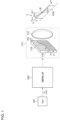
- Fig. 1 is a block diagram illustrating a lamp system 100 of Embodiment 1.
- the lamp system 100 is a headlamp that is mounted on an automobile, and illuminates a field of view ahead of the vehicle with light.
- the automobile can vary the angle of inclination in the front-rear direction, corresponding to the front-rear weight balance.
- the front-rear inclination angle corresponds to rotation around a horizontal axis that extends in the left-right direction of the vehicle body, and is referred to as a pitch angle ⁇ p.
- the lamp system 100 has a function (auto leveling function) that automatically adjusts the optical axis of the headlamp in the pitch direction, corresponding to the pitch angle ⁇ p.
- the lamp system 100 has a high-definition lamp unit 110, a sensor 120, and a controller 200.
- the high-definition lamp unit 110 is an adaptive driving beam lamp which is structured to illuminate a part of, or the entire part of a low beam region.
- the high-definition lamp unit 110 may alternatively cover a part/all of the high beam region, in addition to a part/all of the low beam region.
- the high-definition lamp unit 110 contains a plurality of individually controllable pixels PIX, and emits lamp beam with light distribution corresponded to states of the pixels PIX.
- the high-definition lamp unit 110 typically includes a light emitting element array 112, and an illumination optical system 114.
- the light emitting element array 112 usable here may be an LED array.
- each pixel PIX may be controllable in two gradations of ON and OFF, or may be controllable in multiple gradations.
- the pixels, when structured to be controllable in two gradations of ON and OFF, may alternatively be expressed in multiple gradations with the aid of PWM dimming, by which the individual pixels PIX are switched at high speed, while varying the temporal ratio (duty cycle) between the on-time and the off-time.
- the illumination optical system 114 projects the output light from the light emitting element array 112, to the front of the vehicle.
- the illumination optical system 114 may be a lens optical system, a reflection optical system, or a combination thereof.
- Fig. 1 illustrates a virtual perpendicular screen 2.
- the virtual perpendicular screen 2 is assumed to be a coordinate system with reference to the road face.
- the virtual perpendicular screen 2 may be 10 m, or 25 m away from the vehicle (lamp).
- a light distribution pattern PTN is created with the lamp beam of the high-definition lamp unit 110.
- the light distribution pattern PTN is an intensity distribution of the lamp beam seen on the virtual perpendicular screen 2, which corresponds to an on/off pattern of the plurality of pixels PIX of the light emitting element array 112.
- the correspondence between the position of a certain pixel, with an illumination area on the virtual perpendicular screen 2 ascribed to the pixel, is determined by the illumination optical system 114, and may be occasionally given in a mirror image relation (left-right inversion), up-down inversion, or up-down and left-right inversion.
- the light distribution pattern PTN contains a cut-off line CL.
- the light distribution pattern PTN contains a horizontal cut-off line CLa and an oblique cut-off line CLb, which intersect at an elbow point LB.
- the controller 200 corrects the optical axis of the low beam in the pitch angle direction, corresponding to fluctuation of the pitch angle ⁇ p caused by various factors during stop and travel of the vehicle.
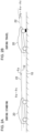
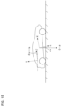
- Figs. 2(a) and (b) are drawings illustrating the pitch angle ⁇ p of the vehicle body.
- Fig. 2(a) illustrates the pitch angle ⁇ p in a state where the vehicle is in a stop mode.
- the pitch angle ⁇ p in a stationary state of the vehicle is defined as static pitch angle ⁇ s.
- the static pitch angle ⁇ s representing the posture of the vehicle when stopped, is also referred to as a standing vehicle posture angle.
- the static pitch angle ⁇ s is determined corresponding, for example, to the number of passengers, riding position, weight of baggage in a baggage compartment, and rigidity of front and rear suspensions.
- an angle formed between a straight line 12 parallel to the road face 10 and a reference line 22 of the vehicle body 20 is defined as a pitch angle ⁇ p, and the direction in which the reference line 22 points upward (nose-up direction) is defined to be positive.
- Fig. 2(b) illustrates the pitch angle ⁇ p of the vehicle in the drive mode.
- the pitch angle ⁇ p of the vehicle in the drive mode may be understood to be the sum of the static pitch angle ⁇ s and a dynamic component (also referred to as dynamic pitch angle or pitch angle variation) ⁇ d.
- the dynamic pitch angle ⁇ d may contain the following components.
- the pitch angle variation upon acceleration or deceleration of the vehicle body, or (ii) the change in the pitch angle due to load change of the vehicle body, which lasts for several seconds, may typically be understood to be DC fluctuation, with a very low frequency component (0.5 Hz or lower).
- the vibration of the vehicle body caused by the irregularity on the road face usually falls within the range from approximately 0.5 to 5 Hz, although depending on the rigidity of the suspension or the vehicle weight.
- the sudden vehicle body vibration typically falls in the range from 0.9 to 2 Hz.
- the prior leveling control has removed vibration exceeding approximately 0.5 Hz through a filter, while assuming it as a noise.
- the prior method has, therefore, not assumed the fast pitch angle variation such as exceeding the cut-off frequency of the filter, out of (i) to (iii), as the matter to be corrected, so that sudden change in the vehicle pitch angle typically due to steep irregularity on the road face during the travel has resulted in sinking down or lifting up of the cut-off line of the low beam.
- this embodiment actively corrects, rather than removing as a noise, the frequency component exceeding 0.5 Hz (approximately 0.5 to 5 Hz, e.g. 1 to 2 Hz) in the pitch angle variation, which has previously been removed as a noise.
- the optical axis correction for correcting pitch angle variation during travel is referred to as dynamic leveling.
- the sensor 120 is provided to enable detection of the dynamic component ⁇ d in the pitch angle ⁇ p, during travel of the vehicle body.
- the sensor 120 in this embodiment contains a gyro sensor.
- the gyro sensor whose orientation of attachment is freely selectable, is preferably attached so as to align one of the detection axes with the left-right horizontal direction of the vehicle body, thereby generating a detection signal S1 that represents angular velocity ⁇ of the rotational movement around the detection axis.
- the gyro sensor may be triaxial, or monoaxial.
- the controller 200 is an electronic control unit (ECU) in which functions related to optical axis correction are integrated, and is assigned to processing regarding the dynamic leveling.
- the controller 200 may be an ECU dedicated to leveling (also referred to as a leveling ECU), may be an ECU integrated with a controller having other functions, or may be separately embodied in a plurality of ECUs.
- the function of the controller 200 may be embodied by software processing, hardware processing, or a combination of software processing and hardware processing.
- the software processing may be specifically implemented by combining a processor (hardware) such as central processing unit (CPU), micro processing unit (MPU), or microcomputer, with software program executed by the processor (hardware).
- the controller 200 may be embodied by combination of a plurality of processors (microcontrollers).
- the hardware processing is specifically implemented by hardware such as application specific integrated circuit (ASIC), controller IC, or field programmable gate array (FPGA).
- ASIC application specific integrated circuit
- controller IC controller IC
- FPGA field programmable gate array
- the controller 200 detects the dynamic component ⁇ d in the pitch angle ⁇ p during travel of the vehicle, by integrating the angular velocity ⁇ p represented by the detection signal S1.
- the dynamic component ⁇ d may be understood as a component, out of the fluctuation of the pitch angle ⁇ p, contained in a frequency band higher than 0.5 Hz.
- a component contained in a predetermined frequency band, out of the fluctuation of the pitch angle ⁇ p is determined as the dynamic component to be corrected.
- the predetermined frequency band may be determined typically within the range from approximately 0.5 Hz to 5 Hz. Which frequency band is to be corrected may only be determined, typically depending on rigidity of the suspension, or the mass of the vehicle body.
- the controller 200 shifts the level of the cut-off line CL in the light distribution pattern PTN (level in the vertical direction V, or, the optical axis), with reference to the predetermined level vo, corresponding to the dynamic component ⁇ d in the pitch angle ⁇ p of the vehicle body during travel.
- the prior leveling control has shifted the optical axis only downwards, for the purpose of suppressing glare.
- the dynamic leveling according to this embodiment will actively shift the level of the cut-off line CL, not only downwards, but also actively upwards.
- control of the level of the cut-off line CL encompasses (1) a case where only the level of the cut-off line is shifted up and down, while fixing the bottom end of the light distribution of the lamp, and (2) a case where the level of the lower end of the light distribution of the lamp is shifted up and down, following the level of the cut-off line, in other words, a case where the entire light distribution of the lamp is shifted up and down.
- the controller 200 shifts the cut-off line CL downwards, corresponding to a positive dynamic pitch angle ⁇ d.
- the controller 200 in this embodiment shifts the cut-off line CL actively also upwards, corresponding to a negative dynamic pitch angle ⁇ d.
- the controller 200 shifts the level of the cut-off line CL up and down with reference to the predetermined level V 0 , so as to cancel the dynamic component ⁇ d in the pitch angle ⁇ p.
- the predetermined level V 0 represents a coordinate in the vertical direction on which the cut-off line CL should fall, when the variation of the pitch angle ⁇ p equals zero.
- the controller 200 shifts an ON-OFF boundary 116 in the plurality of pixels PIX of the light emitting element array 112, in order to shift the cut-off line CL up or down on the virtual perpendicular screen 2.
- the boundary 116 should be shifted, with respect to a certain variation range of the pitch angle ⁇ p, may be determined in terms of geometrical optics. Let the shift amount of pixel be ⁇ y.
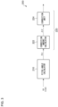
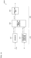
- Fig. 3 is a functional block diagram of a controller 200.
- the controller 200 has a pitch angle calculator 210 and a cut-off line control unit 220.
- the pitch angle calculator 210 detects the dynamic component ⁇ d in the pitch angle ⁇ p, in response to an output of the sensor 120. For example, the pitch angle calculator 210 integrates the angular velocity ⁇ p indicated by the detection signal S1. The pitch angle calculator 210 also optionally subject the integral value to arithmetic processing, to derive the dynamic pitch angle ⁇ d. This arithmetic processing may typically include filtering (band limiting), and moving average processing.
- the cut-off line control unit 220 shifts up or down the level of the cut-off line CL, in response to the dynamic pitch angle ⁇ d.
- the cut-off line control unit 220 has a correction amount calculator 222 and a correction unit 224.
- the correction amount calculator 222 calculates the amount of vertical shift (correction amount ⁇ V) of the cut-off line CL on the virtual perpendicular screen 2, in response to the dynamic pitch angle ⁇ d.
- the positive correction amount ⁇ V corresponds to the upward shift of the cut-off line CL
- the negative correction amount ⁇ V corresponds to the downward shift of the cut-off line CL.
- the correction unit 224 controls the light emitting element array 112, so as to shift the cut-off line CL by the correction amount ⁇ V.
- the light emitting element array 112 has an interface through which image data that specifies ON-OFF (or luminance) of the pixels PIX is input.
- the correction unit 224 in this case may shift up or down the level of the boundary 116 between the on-pixels and the off-pixels contained in the image data, by the number of pixels ⁇ y, corresponding to the correction amount ⁇ V. That is, the correction unit 224 shifts up or down the level of the cut-off line CL (boundary 116) in the light distribution pattern contained in the image data, with reference to the predetermined level yo, so as to cancel the dynamic component ⁇ d in the pitch angle ⁇ p.
- the predetermined level y 0 represents a reference level that corresponds to Vo.
- the correction unit 224 may alternatively shift up or down the level (height) of the boundary between the ON-pixels and the OFF-pixels that corresponds to the lower end of the light distribution pattern, by the number of pixels ⁇ y that corresponds to the correction amount ⁇ V, in addition to the level (height) of the boundary 116 between the ON-pixels and the OFF-pixels that corresponds to the cut-off line CL. That is, the correction unit 224 may shift the entire light distribution pattern up and down, by the number of pixels ⁇ y that corresponds to the correction amount ⁇ V.
- the structure of the lamp system 100 has been described. Next, operations thereof will be explained.
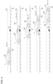
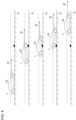
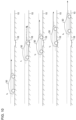
- Fig. 4 is a drawing illustrating an exemplary travel scene of a vehicle.
- a vehicle 30 travels from left to right in the drawing, while getting over a step 14 on the road face 10.
- Fig. 4 illustrates posture of the vehicle 30 at a plurality of times t 0 to t 4 .
- the individual times t 0 to t 4 stand for the following states.
- the dynamic pitch angle ⁇ d at each of the times t 0 , t 2 , and t 4 equals 0.
- the dynamic pitch angle ⁇ d at time t 1 has a positive value ⁇ d 1
- the dynamic pitch angle ⁇ d at time t 2 has a negative value ⁇ d 3 .
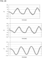
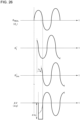
- Fig. 5 is a drawing illustrating a waveform of dynamic pitch angle ⁇ d and a waveform of correction amount ⁇ V, corresponded to the travel scene illustrated in Fig. 4 .
- the dynamic pitch angle ⁇ d swings in the positive direction, then swings in the negative direction, and finally returns to 0.
- the correction amount ⁇ V is generated corresponding to such variation of the dynamic pitch angle ⁇ d.
- Fig. 6 is a drawing illustrating light beams corresponded to the cut-off line of the lamp beam of the headlamp, in the travel scene illustrated in Fig. 4 .
- a beam 32 of the lamp beam may be kept at a constant angle away from the road face 10, with use of the adaptive light driving beam control in compliance with the dynamic pitch angle ⁇ d.
- the lamp system 100 can prevent glare by shifting the cut-off line downwards, when the vehicle 30 sinks in the rear part at time t 1 as illustrated in Fig. 6 . Meanwhile, the lamp system 100 can prevent a far field of view from being looked dark, by shifting the cut-off line upwards, when the vehicle 30 sinks down in the front part at time t 3 as illustrated in Fig. 6 .
- the level of the cut-off line may be kept constant on a virtual perpendicular screen ahead of the vehicle, even if the vehicle 30 causes front-rear vibration (pitching), thereby preventing an object ahead of the vehicle from being looked bright and dark, and thus successfully providing an improved field of view.
- the static pitch angle ⁇ s may be understood to be a reference value of the pitch angle ⁇ p
- the dynamic pitch angle ⁇ d may be understood as a dynamic deviation of the pitch angle ⁇ p from the reference value.
- the controller 200 may therefore be understood to control the high-definition lamp unit 110, so as to keep a constant angle between the beam 32 that corresponds to the cut-off line of the lamp beam, and the road face 10, corresponding to the deviation ⁇ d.
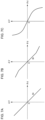
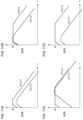
- Figs. 7(a) to (c) are drawings illustrating exemplary relations (control characteristic) between the dynamic pitch angle ⁇ d and the correction amount ⁇ V.
- Equation (2) ⁇ V ⁇ L ⁇ ⁇ d
- the correction amount ⁇ V may be most simply given, as illustrated in Fig. 7(a) , by a linear function having a proportional constant derived from the distance L (referred to as reference gain g 0 ), multiplying the dynamic pitch angle ⁇ d.
- the boundary 116 that corresponds to the cut-off line on the image data is shifted up or down, so that the correction amount ⁇ V is obtainable.
- ⁇ y ⁇ ⁇ ⁇ d
- the correction amount ⁇ V may be specified by a polyline with respect to the dynamic pitch angle ⁇ d, as illustrated in Fig. 7(b) .
- control characteristic as illustrated in Fig. 7(b) may be employable, for the purpose of reducing the correction amount ⁇ V with respect to the unit variation of the dynamic pitch angle ⁇ d, in a region where the variation amount (absolute value of ⁇ d) is large. This case can suppress glare, when control delay occurs in a situation that the nose-dive is immediately followed by the nose-up.
- a more intricate control characteristic may be specified as illustrated in Fig. 7(c) .
- the upward shift of the cut-off line may be invalidated, corresponding to the travel situation.
- the dynamic pitch angle ⁇ d includes a frequency component exceeding the response rate of the controller 200, the glare may be suppressed by invalidating the upward shift of the cut-off line.
- the cut-off line may be invalidated.
- irregularity continues on the road face (for example, 3 seconds or longer in a temporal sense)
- the road face is assumed to be a special one (dirt course, unpaved mountain road, etc.), rather than usual road for driving.
- the pitch angle control may be fixed to the one having been acquired during the stop or stable travel mode.
- the cut-off line when returned back to the previous state, is preferably returned gradually over several seconds, rather than returned promptly.
- the cut-off line is preferably returned gradually while producing blurring or gradation.
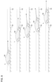
- Fig. 8 is a drawing illustrating glare possibly resulted from correction of the optical axis upon nose-dive.
- the vehicle 30 travels from left to right in the drawing, while passing over a dent 16 on the road face 10.
- Fig. 4 illustrates posture of the vehicle 30 at a plurality of times t 0 to t 4 .
- the individual times t 0 to t 4 stand for the following states.
- the level of the cut-off line is corrected so as to direct the optical axis upwards.
- the controller 200 in this case tries to return the cut-off line to the original predetermined level vo.
- the cut-off line cannot fully return back to the predetermined level vo, and will remain above the predetermined level vo. This would cause illumination of the lamp beam above the horizontal line, and would cause glare.
- the controller 200 tries to correct the level of the cut-off line below the predetermined level vo, so as to direct the optical axis downwards. Also in this case if associated with control delay, the cut-off line cannot fully fall down to the target level that corresponds to the current posture, possibly causing the lamp beam illuminated above the horizontal line, and causing glare.
- control characteristic of the cut-off line CL may differ between the cases where the dynamic pitch angles ⁇ d are positive and negative, in other words, between the cases where the cut-off line CL shifts upwards from the predetermined level, and downwards from the predetermined level.
- the control characteristic herein relates to correlation between the dynamic pitch angle ⁇ d and the correction amount ⁇ V, which is exemplified by the aforementioned function f(), and parameters (gain and order) that define the function f().
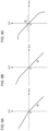
- Figs. 9(a) to (c) are drawings illustrating exemplary relations (control characteristic) between the dynamic pitch angle ⁇ d and the correction amount ⁇ V.
- the example illustrated in Fig. 9(a) has the control characteristic that follows a linear function similarly to as in Fig. 7(a) , but with different gains (inclination) for ⁇ d > 0 (nose-up) and ⁇ d ⁇ 0 (nose-dive).
- the correction amount ⁇ V may be relatively large if ⁇ d > 0, meanwhile the correction amount ⁇ V may be relatively small if ⁇ d ⁇ 0.
- the control characteristic has a slope (reference gain g 0 ) derived from distance L, as expressed by Equation (2). This can reliably prevent glare.
- the slope is smaller than the slope in the region of ⁇ d > 0 which represents the reference gain go. That is, in case of nose-dive, the amount of shifting the optical axis upwards is suppressed. This case can suppress glare possibly exerted on a nearby traffic participant, when control delay occurs in a situation that the nose-dive is immediately followed by the nose-up.
- the problem having been described with reference to Fig. 8 may thus be solved.
- Fig. 10 is a drawing illustrating correction of optical axis, with reference to control characteristic illustrated in Fig. 9(a) .
- Fig. 10 illustrates the control characteristic of Fig. 9(a) adopted to the travel scene same as in Fig. 8 .
- the level of the cut-off line is corrected so as to direct the optical axis upwards.
- ⁇ d ⁇ 0 holds, then the correction amount ⁇ V becomes smaller than the correction amount in the case of Fig. 8 .
- a dash-dot line represents the optical axis in Fig. 8
- a solid line represents the optical axis derived from the control characteristic in Fig. 9(a) .
- the controller 200 in this case tries to return the cut-off line to the original predetermined level vo. Since the correction amount ⁇ V in the just-preceding nose-dive is suppressed low, so that the cut-off line can return to the predetermined level v 0 even in case of control delay. This can keep the lamp beam below the horizontal line, thus suppressing glare.
- Fig. 9(b) has a negative threshold value ⁇ TH specified therein, so that the slope represents the reference gain g 0 in the region of ⁇ d > ⁇ TH .
- the slope is smaller than the slope that represents the reference gain go.
- the far field of view may be maintained by correcting the optical axis with a basic gain.
- the amount of upward shift of the optical axis is suppressed. This case can suppress glare possibly exerted on a nearby traffic participant, when control delay occurs in a situation that the nose-dive is immediately followed by the nose-up. The problem described with reference to Fig. 8 may thus be solved.
- the slope represents the reference gain go in the region of ⁇ d ⁇ 0, whereas the slope increases in the region of ⁇ d > 0, as the variation amount (absolute value) increases. This directs the optical axis downwards more largely than theoretically required, in a situation with large nose-up. This can more reliably suppress glare.
- the slope decreases in the region of ⁇ d ⁇ 0, as the variation amount (absolute value) increases.
- This directs the optical axis upwards to a lesser extent than theoretically required, in a situation with deep nose-dive. This can suppress glare possibly exerted on a nearby traffic participant, when control delay occurs in a situation that the posture changes to nose-up immediately thereafter.
- the problem described with reference to Fig. 8 may thus be solved.
- the transfer function can contain a filter element, so that the control characteristic, or a filter characteristic, may differ between the cases where the cut-off line CL shifts upwards from the predetermined level, and downwards from the predetermined level.
- Figs. 11(a) to (d) are drawings illustrating exemplary relations (control characteristic) between the dynamic pitch angle ⁇ d and the correction amount ⁇ V.
- frequency characteristic cut-off frequency
- the gain equals to the reference gain go in both regions of ⁇ d > 0 and ⁇ d ⁇ 0, with different frequency characteristics. More specifically, the dynamic pitch angle ⁇ d is corrected over a wider frequency range in the region of ⁇ d > 0 (nose-up), thus reliably preventing glare. Meanwhile in the region ⁇ d ⁇ 0 (nose-dive), the frequency band over which the dynamic pitch angle ⁇ d is corrected is narrowed. This can reduce the risk of glare due to control delay.
- the gain equals to the reference gain go in both regions of ⁇ d > 0 and ⁇ d ⁇ 0 similarly to as in Fig. 11(b) , but with different frequency characteristics.
- the frequency band over which the dynamic pitch angle ⁇ d is corrected is narrowed in the region of ⁇ d ⁇ 0 (nose-dive), but with the band for correction shifted to a higher region than in Fig. 11(b) .
- both of the gain g and the frequency characteristic are different for the regions of ⁇ d > 0 and ⁇ d ⁇ 0.
- the speed at which the cut-off line CL is shifted up and down corresponding to the posture of the vehicle body may be changed. More specifically, the speed of upward shifting of the cut-off line may be slower than the speed of downward shifting of the cut-off line. This makes it less likely to cause glare, after upward correction of the cut-off line CL.
- the upward shift of the cut-off line may be invalidated, corresponding to the travel situation.
- the dynamic pitch angle ⁇ d includes a frequency component exceeding the response rate of the controller 200, the glare may be suppressed by invalidating the upward shift of the cut-off line.
- the cut-off line may be invalidated.
- irregularity continues on the road face (for example, 3 seconds or longer in a temporal sense)
- the road face is assumed to be a special one (dirt course, unpaved mountain road, etc.), rather than usual road for driving.
- the pitch angle control may be fixed to the one having been acquired during the stop or stable travel mode.
- the cut-off line when returned back to the previous state, is preferably returned gradually over several seconds, rather than returned promptly.
- the cut-off line is preferably returned gradually while producing blurring or gradation.
- the controller 200 may change the intensity distribution of the light distribution (illuminance distribution), in addition to the shifting of the cut-off line (leveling control).
- Figs. 12(a) to (c) are drawings illustrating exemplary control of an intensity distribution of light distribution.
- Fig. 12(a) exemplifies a most standard light distribution control, in which only the cut-off line CL is shifted upwards, with the illuminance kept substantially constant. Note that Figs. 12(a) to (c) depict the illuminance by hatching with varied density, wherein the larger the density, the higher the illuminance.
- the controller 200 lowers the illuminance in the region above the predetermined level vo, to a level lower than the illuminance (prescribed value) in Fig. 12(a) . This makes glare less likely to occur, while maintaining the driver's far field of view.
- the light distribution has an intensity distribution in which the illuminance in the region above the predetermined level V 0 is gradated so as to be gradually dimmed upwards. This makes glare less likely to occur, while maintaining the driver's far field of view.
- the embodiment has detected the dynamic component of the pitch angle with use of the gyro sensor.
- the present disclosure is, however, not limited thereto.
- the dynamic component of the pitch angle may be detected with use of a combination of a front vehicle height sensor arranged on the front suspension of the vehicle body, and a rear vehicle height sensor arranged on the rear suspension of the vehicle body.
- the embodiment has constituted the high-definition lamp unit 110 with the light emitting element array 112.
- the high-definition lamp unit 110 may contain a light source that generates light with a substantially flat intensity distribution, and a spatial light modulator that spatially patterns the emitted light of the light source.
- the spatial light modulator is exemplified by digital micromirror device (DMD), and liquid crystal device.
- the controller 200 shifts the level of the cut-off line CL up and down is not limited to that described in the embodiments.
- the light emitting element array 112 may have a pixel shifting function. In this case, the light emitting element array 112 may only be given the image data as the reference, and the pixel shift amount ⁇ y.
- Control of the optical axis that is, control of the height of the cut-off line is not limited to pixel control of the high-definition lamp unit 110 (electronic leveling).
- an ordinary low beam unit may be structured to be controllable with a high-speed leveling actuator, thus making it possible to control the height of the cut-off line by changing the inclination of the low beam unit (referred to as mechanical leveling).
- the position of the light emitting element array 112 may be structured to allow mechanical shifting.
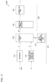
- Fig. 13 is a block diagram illustrating a lamp system 100 of Embodiment 2.
- the lamp system 100 is a headlamp that is mounted on an automobile, and illuminates a field of view ahead of the vehicle with light.
- the automobile can vary the angle of inclination in the front-rear direction, corresponding to the front-rear weight balance.
- the front-rear inclination angle corresponds to rotation around a horizontal axis that extends in the left-right direction of the vehicle body, and is referred to as a pitch angle ⁇ p.
- the lamp system 100 has a function (auto leveling function) that automatically adjusts the optical axis of the headlamp in the pitch direction, corresponding to the pitch angle ⁇ p.
- the lamp system 100 has a high-definition lamp unit 110, a first sensor 120, a second sensor, and a controller 200.
- the high-definition lamp unit 110 is an adaptive driving beam lamp which is structured to illuminate a part of, or the entire part of a low beam region, with light.
- the high-definition lamp unit 110 may alternatively cover a part/all of the high beam region, in addition to a part/all of the low beam region.
- the high-definition lamp unit 110 contains a plurality of individually controllable pixels PIX, and emits lamp beam with light distribution corresponded to states of the pixels PIX.
- the high-definition lamp unit 110 typically includes a light emitting element array 112, and an illumination optical system 114.
- the light emitting element array 112 usable here may be an LED array.
- each pixel PIX may be controllable in two gradations of ON and OFF, or may be controllable in multiple gradations.
- the pixels, when structured to be controllable in two gradations of ON and OFF, may alternatively be expressed in multiple gradations with the aid of PWM dimming, by which the individual pixels PIX are switched at high speed, while varying the temporal ratio (duty cycle) between the on-time and the off-time.
- the illumination optical system 114 projects the output light from the light emitting element array 112, to the front of the vehicle.
- the illumination optical system 114 may be a lens optical system, a reflection optical system, or a combination thereof.
- Fig. 13 illustrates a virtual perpendicular screen 2.
- the virtual perpendicular screen 2 is assumed to be a coordinate system with reference to the road face.
- the virtual perpendicular screen 2 may be 10 m, or 25 m away from the vehicle (lamp).
- a light distribution pattern PTN is created with the lamp beam of the high-definition lamp unit 110.
- the light distribution pattern PTN is an intensity distribution of the lamp beam seen on the virtual perpendicular screen 2, which corresponds to an on/off pattern of the plurality of pixels PIX of the light emitting element array 112.
- the correspondence between the position of a certain pixel, with an illumination area on the virtual perpendicular screen 2 ascribed to the pixel, is determined by the illumination optical system 114, and may be occasionally given in a mirror image relation (left-right inversion), up-down inversion, or up-down and left-right inversion.
- the light distribution pattern PTN contains a cut-off line CL.
- the light distribution pattern PTN contains a horizontal cut-off line CLa and an oblique cut-off line CLb, which intersect at an elbow point LB.
- the controller 200 corrects the optical axis of the low beam in the pitch angle direction, corresponding to fluctuation of the pitch angle ⁇ p caused by various factors during stop and travel of the vehicle.
- the controller 200 shifts an ON-OFF boundary 116 in the plurality of pixels PIX of the light emitting element array 112, in order to shift the cut-off line CL up or down on the virtual perpendicular screen 2.
- the boundary 116 should be shifted, with respect to a certain variation range of the pitch angle ⁇ p, may be determined in terms of geometrical optics. Let the shift amount of pixel be ⁇ y.
- the controller 200 subjects, similarly to as in Embodiment 1, the frequency component exceeding 0.5 Hz in the pitch angle variation, which has previously been removed as a noise, to the dynamic leveling.
- the controller 200 also corrects the optical axis according to the static pitch angle (standing vehicle posture angle) ⁇ s illustrated in Fig. 2(a) . More specifically, the controller controls to direct the optical axis of the lamp downwards, corresponding to change in the static load of the vehicle in a stop mode. This is referred to as static leveling.
- the static leveling has been practiced in the prior vehicle lamp, with use of a G sensor (acceleration sensor) or a vehicle height sensor.
- the first sensor 120 and the second sensor 122 are provided.
- the first sensor 120 is provided mainly to enable detection of the dynamic component ⁇ d in the pitch angle ⁇ p of the vehicle body during travel.
- the first sensor 120 contains a gyro sensor.
- the gyro sensor whose orientation of attachment is freely selectable, is preferably attached so as to align one of the detection axes with the left-right horizontal direction of the vehicle body, thereby generating a first detection signal S1 that represents angular velocity ⁇ p of the rotational movement around the detection axis.
- the gyro sensor may be triaxial, or monoaxial.
- the second sensor 122 is an acceleration sensor (G sensor).
- the second sensor 122 outputs a detection signal S2 that contains accelerations ⁇ x , ⁇ y , and ⁇ z for the three axes, respectively.
- a detection signal S2 that contains accelerations ⁇ x , ⁇ y , and ⁇ z for the three axes, respectively.
- a composite vector of the accelerations ⁇ x , ⁇ y , and ⁇ z along the three axes is directed to the direction of gravity.
- a composite vector of the accelerations ⁇ x , ⁇ y , and ⁇ z of the three axes gives a composite vector of gravity and an acceleration vector of the vehicle body.
- the first sensor 120 and the second sensor 122 may be a six-axis sensors in which an acceleration sensor and a gyro sensor are integrated.
- the controller 200 is an electronic control unit (ECU) in which functions related to optical axis correction are integrated, and is assigned to processing regarding the static leveling and the dynamic leveling.
- the controller 200 may be an ECU dedicated to leveling (also referred to as a leveling ECU), may be an ECU integrated with a controller having other functions, or may be separately embodied in a plurality of ECUs.
- the function of the controller 200 may be embodied by software processing, hardware processing, or a combination of software processing and hardware processing.
- the software processing may be specifically implemented by combining a processor (hardware) such as central processing unit (CPU), micro processing unit (MPU), or microcomputer, with software program executed by the processor (hardware).
- the controller 200 may be embodied by combination of a plurality of processors (microcontrollers).
- the hardware processing is specifically implemented by hardware such as application specific integrated circuit (ASIC), controller IC, or field programmable gate array (FPGA).
- ASIC application specific integrated circuit
- controller IC controller IC
- FPGA field programmable gate array
- the controller 200 detects the pitch angle ⁇ p of the vehicle, in response to the detection signal S1 generated by the first sensor 120 and the second detection signal S2 generated by the second sensor 122, and controls the height of the cut-off line of the light distribution corresponding to the pitch angle ⁇ p.
- the pitch angle ⁇ p contains static pitch angle ⁇ s (standing vehicle posture angle) and dynamic pitch angle ⁇ p.
- Fig. 14 is a functional block diagram of a controller 200A of Example 1.
- the controller 200A has a pitch angle calculator 210 and a cut-off line control unit 220.
- the pitch angle calculator 210 generates angle information necessary for optical axis correction (leveling control), that is, the pitch angle ⁇ p, from the two detection signals S1 and S2.
- the pitch angle calculator 210 contains an integrator 212 and an acceleration direction calculator 214.
- the integrator 212 calculates a first pitch angle ⁇ j by integrating the angular velocity ⁇ p represented by the first detection signal S1.
- the acceleration direction calculator 214 calculates a second pitch angle ⁇ a that represents the acceleration direction ⁇ , from accelerations ⁇ x , ⁇ y , and ⁇ z represented by the second detection signal S2.
- Fig. 15 is a drawing illustrating the second pitch angle ⁇ a.
- the x-, y-, and z-axes of the acceleration sensor are defined in parallel to X-, Y-, and Z-axes of the vehicle body, respectively.
- the X-axis of the vehicle body is defined to align with the travel direction, the Y-axis with the left-right direction, and the Z-axis with the up-down direction.
- the second pitch angle ⁇ a is defined as the angle between the z-axis of the acceleration sensor and acceleration vector ⁇ .
- the second pitch angle ⁇ a is then given by an angle between a straight line in parallel to the road face and the X-axis of the vehicle body, and coincides with the static pitch angle ⁇ s illustrated in Fig. 2(a) .
- the pitch angle calculator 210 may contain a filter (low-pass filter or band-pass filter) for removing a noise component, wherein the cut-off frequency may only be determined so that the frequency component to be corrected can pass therethrough, for the purpose of correcting high-speed pitch angle variation.
- the cut-off frequency may, therefore, only be determined between the frequency of the noise and the maximum value of the frequency to be corrected.
- the cut-off frequency needs to be determined so as to fully attenuate a region at 100 Hz, and may thus be determined to approximately 1/2 to 1/3 of a noise frequency of 100 Hz, which may be 50 Hz for example.
- the second pitch angle ⁇ a is correlated to the static pitch angle ⁇ s
- the first pitch angle ⁇ j is correlated to the dynamic pitch angle ⁇ d.
- the static pitch angle ⁇ s (standing vehicle posture angle) may be estimated from the second pitch angle ⁇ a of the vehicle that stands still.
- the acceleration sensor structured to acquire the direction and inclination of the gravitational acceleration, cannot discriminate whether the car in a stop mode inclines because it is on a slope, or inclines due to load
- the standing vehicle posture angle (static pitch angle ⁇ s) may be estimated with use of a known technique (see Patent Literature 3, for example).
- the first pitch angle ⁇ j may be set as the dynamic pitch angle ⁇ d. For example, by resetting the integral value during a period the angular velocity ⁇ p in the pitch direction is kept zero, and by restarting the integration when the angular velocity ⁇ p becomes non-zero, the integral value is then understood to represent the dynamic pitch angle ⁇ d.
- the cut-off line control unit 220 conducts the static leveling with reference to the static pitch angle ⁇ s, and conducts the dynamic leveling with reference to the dynamic pitch angle ⁇ p. For example, the cut-off line control unit 220 controls the level Vo that gives the reference of the cut-off line CL, with use of the static pitch angle ⁇ s. The cut-off line control unit 220 also shifts the cut-off line CL up and down relative to the reference level V 0 , with reference to the dynamic pitch angle ⁇ d.
- the dynamic leveling may alternatively be applied only for a case where the dynamic pitch angle ⁇ p, derived from the first pitch angle ⁇ j, is larger than a predetermined threshold value.
- the leveling control by the cut-off line control unit 220 There are two possible schemes for the leveling control by the cut-off line control unit 220. One of them relates to a scheme of controlling the optical axis with use of the pitch angle ⁇ p. The scheme is referred to as combined control. For the combined control, it suffices to set the level of the cut-off line CL with use of the pitch angle ⁇ p as a control angle.
- the pitch angle ⁇ p may be generated by adding ⁇ j and ⁇ s.
- Another leveling control relates to a scheme of controlling the optical axis, while separating the static pitch angle ⁇ s and the dynamic pitch angle ⁇ d.
- the scheme is referred to as separated control.
- the separated control will be described below.
- the cut-off line control unit 220 has a correction amount calculator 222 and a correction unit 224.
- the correction amount calculator 222 calculates the level Vo which gives a reference of the cut-off line CL on the virtual perpendicular screen 2, with use of the static pitch angle ⁇ s.
- the correction amount calculator 222 also calculates the amount of vertical shift (correction amount ⁇ V) of the cut-off line CL, with reference to the dynamic pitch angle ⁇ d.
- the positive correction amount ⁇ V corresponds to the upward shift of the cut-off line CL
- the negative correction amount ⁇ V corresponds to the downward shift of the cut-off line CL.
- the correction unit 224 controls the light emitting element array 112, so as to shift the cut-off line CL from the reference level V 0 , by the correction amount ⁇ V.
- the light emitting element array 112 has an interface through which image data that specifies ON-OFF (or luminance) of the pixels PIX is input.
- the correction unit 224 in this case may shift up or down the level of the boundary 116 between the on-pixels and the off-pixels contained in the image data, by the number of pixels ⁇ y, corresponding to the correction amount ⁇ V. That is, the correction unit 224 shifts up or down the level of the cut-off line (boundary 116) in the light distribution pattern contained in the image data, with reference to the predetermined level yo, so as to cancel the dynamic component ⁇ d in the pitch angle ⁇ p.
- the predetermined level y 0 represents a reference level that corresponds to Vo.
- the correction unit 224 may alternatively shift up or down the level (height) of the boundary between the ON-pixels and the OFF-pixels that corresponds to the lower end of the light distribution pattern, by the number of pixels ⁇ y that corresponds to the correction amount ⁇ V, in addition to the level (height) of the boundary 116 between the ON-pixels and the OFF-pixels that corresponds to the cut-off line CL. That is, the correction unit 224 may shift the entire light distribution pattern up and down, by the number of pixels ⁇ y that corresponds to the correction amount ⁇ V.
- Example 2 The basic structure of the controller of Example 2 is similar to that illustrated in Fig. 14 .
- the static pitch angle ⁇ s is determined from the second pitch angle ⁇ a, similarly to as in Example 1. That is, the static leveling is the same as in Example 1.
- Example 2 is different from Example 1, in terms of the dynamic leveling. More specifically, the dynamic pitch angle ⁇ d used in the dynamic leveling is determined not only from the first pitch angle ⁇ j, but also from changes in the second pitch angle ⁇ a.
- Fig. 16 is a drawing illustrating a second pitch angle ⁇ a sensed by the second sensor 122.
- a section T1 corresponds to a state of the vehicle that stands still on an unsloped road face.
- the second pitch angle ⁇ a of the vehicle that stands still represents the static pitch angle (standing vehicle posture angle) ⁇ s.
- Section T2 corresponds to travel on a flat road.
- the second pitch angle ⁇ a is kept substantially constant, despite slight changes.
- a section T3 corresponds to an uphill with inclination ⁇ 1.
- the second pitch angle ⁇ a increases by ⁇ 1, from the static pitch angle ⁇ s.
- the change in second pitch angle ⁇ a due to the slope does not affect the posture of the vehicle body posture, and is therefore irrelevant to the dynamic pitch angle ⁇ d, so that the leveling control will not take place.
- a section T4 corresponds to a downhill with inclination ⁇ 2.
- the second pitch angle ⁇ a decreases by ⁇ 2, from the static pitch angle ⁇ s.
- the change in second pitch angle ⁇ a due to the slope does not affect the posture of the vehicle body posture, and is therefore irrelevant to the dynamic pitch angle ⁇ d, so that the leveling control will not take place.
- a section T5 corresponds to a period of acceleration.
- the acceleration follows a normal mode, which is distinguished from sudden acceleration described later.
- the posture changes due to nose-up. This makes the second pitch angle ⁇ a larger than the static pitch angle ⁇ s.
- the cut-off line control unit 220 sets the fluctuation range ⁇ a - ⁇ s of the second pitch angle ⁇ a as the dynamic pitch angle ⁇ d, and corrects the optical axis with reference to the dynamic pitch angle ⁇ d.
- the scheme is referred to as slow dynamic leveling.
- a section T6 corresponds travel over the road face with irregularity.
- the second pitch angle ⁇ a fluctuates towards both sides of the static pitch angle ⁇ s.
- the cut-off line control unit 220 sets the fluctuation range ⁇ a - ⁇ s of the second pitch angle ⁇ a as the dynamic pitch angle ⁇ d, and shifts the optical axis up and down, with reference to the dynamic pitch angle ⁇ d.
- the scheme is referred to as fast dynamic leveling.
- Fluctuation of the dynamic pitch angle ⁇ d during travel on the irregular road face is also detected as the first pitch angle ⁇ j.
- the leveling control in this case may rely upon either ⁇ j or ( ⁇ a - ⁇ d).
- the leveling control may rely upon the first pitch angle ⁇ j.
- the leveling control may rely upon averaging of ⁇ j and ( ⁇ a - ⁇ d).
- Fig. 17 is a functional block diagram of a controller 200B of Example 3.
- the controller 200A has the pitch angle calculator 210 and the cut-off line control unit 220, similarly as illustrated in Fig. 14 .
- the pitch angle calculator 210 has a synthesis unit 216 and a travel condition determination unit 218, in addition to the integrator 212 and the acceleration direction calculator 214.
- the synthesis unit 216 synthesizes the first pitch angle ⁇ j and the second pitch angle ⁇ a, to generate the pitch angle ⁇ p which is angle information necessary for the optical axis correction (leveling control).
- the pitch angle ⁇ p contains the static pitch angle ⁇ s and the dynamic pitch angle ⁇ d, as described above.
- cut-off line control unit 220 although allowed both for combined control and separation control, will now be assumed to rely upon combined control.
- the synthesis unit 216 conducts weighted addition of the first pitch angle ⁇ j and the second pitch angle ⁇ a, to estimate the pitch angle ⁇ p with use of Equation (1).
- ⁇ p ⁇ ⁇ ⁇ j + ⁇ ⁇ ⁇ a
- the travel condition determination unit 218 determines the travel condition, with reference to information from the vehicle (referred to as vehicle information), and/or sensor information. Examples of the vehicle information include vehicle speed, steering angle, camera image, map information, infrastructure information, suspension setting, and vehicle weight.
- the sensor information includes at least one of the first detection signal S1, the second detection signal S2, or the first pitch angle ⁇ j or the second pitch angle ⁇ a derived therefrom respectively.
- the weighting factor ⁇ may therefore be set, with reference to at least one of the vehicle information or the sensor information.
- the leveling control with reference to the output of the second sensor 122 is enabled.
- the leveling control with reference to the first pitch angle ⁇ j is enabled, so as to make the control adaptive to the rapid pitch angle variation.
- the pitch angle ⁇ p during travel on the flat road is then calculated, while increasing the weighting of the acceleration sensor, such as setting ⁇ to approximately 0.1 to 0.5.
- the frequency of vibration caused by irregularity such as gravel is still higher than 5 Hz, and may even typically be 10 to 20 Hz.
- even integration of the outputs of the gyro sensor would fail to calculate a correct pitch angle ⁇ j, or the leveling control would not be fully adaptive.
- the pitch angle ⁇ p for the travel over small irregularity, is therefore calculated by setting ⁇ to approximately 0.1 to 0.5, to increase the weighting of the acceleration sensor. This enables the control with use of an average value from which frequency component higher than 5 Hz has been excluded as a noise, thereby making the control less labor-consuming.
- ⁇ may be set to 0.5 to 1.0. Since the pitch angle in this case is predicted to sharply change, so that ⁇ is set large to make influence of the gyro sensor dominant, thus enabling rapid dynamic leveling.
- ⁇ may be set to 0.5 to 1.0. Since the pitch angle in this case is predicted to sharply change, so that ⁇ is set large to make influence of the gyro sensor dominant, thus enabling rapid dynamic leveling.
- ⁇ is preferably set to 0.1 to 0.5, since the pitch angle ⁇ p is considered to be stable.
- ⁇ may be set to 0.5 to 1.0. Since rapid fluctuation of the pitch angle ⁇ p may occur in this case, the gyro sensor may be largely weighted, thus enabling the dynamic leveling adaptive to dynamic fluctuation of the pitch angle.
- the lamp system 100 of Embodiment 2 having the first sensor 120 and the second sensor 122 combined therein, enables independent detection of static change in posture (static change in pitch angle) of a vehicle body typically depending on the number of passengers, the weight of baggage and the weight of fuel; and sharp change in the pitch angle due to slope of road face on which the vehicle travels, and irregularity or undulation that resides on the road face. This also enables control of the light distribution adaptive to the nature of the detected pitch angle, and can therefore suppress glare due to sudden vibration of the vehicle body during travel.
- the second sensor 122 may employ a vehicle height sensor, in place of the acceleration sensor.
- the vehicle height sensor may be constituted solely by a rear vehicle height sensor, or by a hybrid system of the rear vehicle height sensor and a front vehicle height sensor.
- the embodiment has constituted the high-definition lamp unit 110 with the light emitting element array 112.
- the high-definition lamp unit 110 may contain a light source that generates light with a substantially flat intensity distribution, and a spatial light modulator that spatially patterns the emitted light of the light source.
- the spatial light modulator is exemplified by digital micromirror device (DMD), and liquid crystal device.
- the controller 200 shifts the level of the cut-off line CL up and down is not limited to that described in the embodiments.
- the light emitting element array 112 may have a pixel shifting function. In this case, the light emitting element array 112 may only be given the image data as the reference, and the pixel shift amount ⁇ y.
- Control of the optical axis that is, control of the height of the cut-off line is not limited to pixel control of the high-definition lamp unit 110 (electronic leveling).
- an ordinary low beam unit may be structured to be controllable with a high-speed leveling actuator, thus making it possible to control the height of the cut-off line by changing the inclination of the low beam unit (referred to as mechanical leveling).
- the position of the light emitting element array 112 may be structured to allow mechanical shifting.
- the electronic leveling and the mechanical leveling may be combined.
- the electronic leveling may be applied to sharp changes in the pitch angle
- the mechanical leveling may be applied for gradual changes in the static pitch angle.
- the optical axis was actively controlled to direct upwards upon forward sink (nose-dive) of the vehicle body during travel, to which application of the present disclosure is not limited.
- the upward control may alternatively be limited to the static leveling, meanwhile the dynamic leveling may take part only in controlling the optical axis directed downwards, without controlling the optical axis directed upwards.
- the upward control of the optical axis may alternatively be limited to the static leveling and to the slow dynamic leveling, meanwhile the rapid dynamic leveling may take part only in controlling the optical axis directed downwards, without controlling the optical axis directed upwards.
- Fig. 18 is a drawing illustrating an exemplary design of a vehicle 500A equipped with a lamp system 100.
- the lamp system 100 has the high-definition lamp unit 110, the controller 200, the first sensor 120, and the second sensor 122.
- the high-definition lamp unit 110 is built in the headlamp 510A.
- the first sensor 120 which is a gyro sensor
- the second sensor 122 that contains an acceleration sensor or a vehicle height sensor, are provided in a cabin 504.
- the controller 200 has the pitch angle calculator 210 and the cut-off line control unit 220, as has been illustrated in Fig. 3 .
- the pitch angle calculator 210 and the cut-off line control unit 220 are mounted as the same hardware (processor), on a headlamp 510A side. More specifically, the pitch angle calculator 210 and the cut-off line control unit 220 are mounted on a second processor 542 that is provided on the headlamp 510A side, that is, outside a cabin 504 (inside an engine room).
- the second processor 542 can be a part of a unit called control module 540.
- the control module 540 may contain, for example, a power supply circuit that supplies power to the high-definition lamp unit 110, in addition to the second processor 542.
- Each of the first processor 532 and the second processor 542 may be a microcontroller that contains a software-controllable CPU.
- the first sensor 120 and the first processor 532 are integrated into a unit called leveling ECU 530.
- the second sensor 122 when given as an acceleration sensor, may also be built in the leveling ECU 530.
- Each of the first sensor 120 and the second sensor 122 may be a six-axis sensor 124 in which a gyro sensor and an acceleration sensor are integrated.
- the first processor 532 inside the cabin 504, and the second processor 542 outside the cabin 504 are connected with a vehicle bus 550 such as CAN, or through other interface.
- the first processor 532 supplies the angular velocity signal derived from the first detection signal S1 that is generated by first sensor 120, directly to the second processor 542. That is, the second processor 542 functions as an interface of the vehicle bus 550.
- the second processor 542 integrates the angular velocity signal, converts the result into the pitch angle information (first pitch angle ⁇ j), and controls the high-definition lamp unit 110 with use of the first pitch angle ⁇ j.
- the headlamp 510A is relatively easily attachable to and detachable from the vehicle body 502 as compared with other car components, so that the positional relation between the headlamp 510A and the vehicle body 502 is expected to contain a certain degree of error.
- the structure, having the first sensor 120 as the gyro sensor built in or externally attached to the headlamp 510A, would degrade detection accuracy of change in the pitch angle ⁇ , due to limited accuracy of assembly of the headlamp 510A to the vehicle body 502. For improved detection accuracy, some calibration will be necessary.
- the error in the positional relation between the vehicle body 502 and the gyro sensor may be reduced, by isolating the gyro sensor, or the first sensor 120, from the headlamp 510A and instead by arranging it in the cabin 504, whereby also temperature fluctuation of the gyro sensor may be suppressed. This successfully enhances the detection accuracy of the pitch angle variation.
- Fig. 19 is a drawing illustrating another exemplary design of a vehicle 500B equipped with the lamp system 100.
- the pitch angle calculator 210 and the cut-off line control unit 220 are mounted as separate processors. More specifically, the pitch angle calculator 210 is mounted on the first processor 532 in the cabin 504, meanwhile the cut-off line control unit 220 is mounted on the second processor 542 on the headlamp 510B side.
- the cut-off line control unit 220 of the first processor 532 integrates the angular velocity signal that is the output of the first sensor 120, to calculate the first pitch angle ⁇ j.
- the cut-off line control unit 220 also calculates the second pitch angle ⁇ a from the output of the second sensor 122.
- the first processor 532 transmits the pitch angle information ⁇ , derived from the first pitch angle ⁇ j and the second pitch angle ⁇ a, to the second processor 542.
- the pitch angle information ⁇ may contain both the first pitch angle ⁇ j and the second pitch angle ⁇ a, or may be information obtained by synthesizing the first pitch angle ⁇ j and the second pitch angle ⁇ a.
- the second processor 542 that corresponds to the cut-off line control unit 220 controls the high-definition lamp unit 110, with use of the pitch angle information ⁇ .
- the error in the positional relation between the vehicle body 502 and the gyro sensor may be reduced, by isolating the gyro sensor, or the first sensor 120, from the headlamp 510B and instead by arranging it in the cabin 504, whereby also temperature fluctuation of the gyro sensor may be suppressed, similarly to as in the design illustrated in Fig. 18 .
- the design illustrated in Fig. 19 has the following advantages over the design illustrated in Fig. 18 . A possible problem in the design illustrated in Fig. 18 will be described.
- Fig. 20 is a drawing illustrating signal transmission and processing in the design illustrated in Fig. 18 .
- the angular velocity signal ⁇ p which is an output of the gyro sensor, is generated at a predetermined sampling rate (typically 1 kHz, or 1 ms cycle). Data volume of the angular velocity signal ⁇ p is therefore large, which results in transmission delay ⁇ d when the signal is transmitted from the first processor 532 to the second processor 542 through the vehicle bus 550.
- the second processor 542 receives the delayed angular velocity signal ⁇ p', through the vehicle bus 550.
- the second processor 542 then integrates the angular velocity signal ⁇ p' to convert it into the first pitch angle ⁇ j. While ignoring the delay of processing, the first pitch angle ⁇ j will be delayed by time ⁇ behind the original angular velocity signal ⁇ p. That is, the transmission delay ⁇ d through the vehicle bus 550 limits the response speed of the lamp system 100. Speed-up of response is, however, difficult to be achieved by a prior CAN, and needs employment of the vehicle bus 550 with small transmission delay ⁇ d, which eventually pushes up the cost.
- a possible measure for reducing the transmission delay ⁇ d is to reduce the data volume to be transmitted, typically by thinning out sampling of the angular velocity signal ⁇ p. This measure, however, increases error in the pitch angle ⁇ j obtainable by integrating the angular velocity signal ⁇ p. That is, the leveling control will degrade the accuracy.
- Fig. 21 is a drawing illustrating signal transmission and processing in the design illustrated in Fig. 19 .
- the first processor 532 in the cabin converts, by integration, the angular velocity signals ⁇ p into the first pitch angle ⁇ j. Since this stage is not yet affected by the transmission delay ⁇ d, so that the first pitch angle ⁇ j may be calculated substantially in real time, or only with a very small delay, if the calculation delay is ignored.
- the first processor 532 transmits the first pitch angle information ⁇ j', derived from the first pitch angle ⁇ j, through the vehicle bus 550 to the second processor 542.
- the speed (update rate), at which the second processor 542 updates the light distribution of the high-definition lamp unit 110, may be approximately several tens Hz to 100 Hz (60 fps, 16.6 ms cycle, for example). That is, the first pitch angle ⁇ j may only be supplied to the second processor 542, at a rate of approximately several tens Hz to 100 Hz (60 fps, 16.6 ms cycle, for example). In other words, the first processor 532 is no longer necessary to transmit all samples of the calculated first pitch angle ⁇ j to the second processor 542, and may only transmit the downsampled first pitch angle ⁇ j' to the second processor 542.
- This case can reduce the number of samples, or the data volume, to be transmitted through the vehicle bus 550, down from the design illustrated in Fig. 18 .
- the design illustrated in Fig. 19 may employ a vehicle bus 550 with a slower transmission rate, as compared with the design illustrated in Fig. 18 .
- the first processor 532 generates a future predicted value ⁇ j ⁇ of the first pitch angle ⁇ j, from the output of the first sensor 120.
- the predicted value ⁇ j ⁇ preferably has a value at or after a time (t i + ⁇ d) that is ⁇ d ahead of current time t i .
- a technique of predicting the first pitch angle ⁇ j is not particularly limited.
- the second processor 542 conducts the leveling control, with reference to the predicted value ⁇ j ⁇ of the first pitch angle.
- Fig. 22 is a drawing illustrating the cut-off line control with reference to the predicted value of pitch angle.
- ⁇ REAL represents an actual pitch angle.
- the first processor 532 integrates the outputs of the gyro sensor, to generate the first pitch angle ⁇ j that represents the pitch angle ⁇ REAL .
- ⁇ j ⁇ represents a predicted value of the first pitch angle ⁇ j, generated by the first processor 532.
- the predicted value ⁇ j represents the first pitch angle ⁇ j at future time (t i + ⁇ ).
- the first processor 532 transmits the predicted value ⁇ j ⁇ to the second processor 542.
- ⁇ is now considered to be substantially equal to the transmission delay ⁇ d from the first processor 532 to the second processor 542.
- ⁇ j ⁇ RX represents the predicted value ⁇ j ⁇ received by the second processor 542.
- the second processor 542 conducts the leveling control, with reference to the received pitch angle ⁇ j ⁇ RX .
- ⁇ V represents a control amount of the leveling control.
- ⁇ j ⁇ RX comes behind ⁇ j ⁇ , with propagation delay ⁇ d.
- the ⁇ j ⁇ RX will coincide with the real pitch angle ⁇ REAL on the temporal axis.
- the waveform of ⁇ V therefore coincides with the real pitch angle ⁇ REAL on the temporal axis, thus making it possible to reduce the influence of the transmission delay ⁇ d in the leveling control.
- the first processor 532 may predict the first pitch angle ⁇ j by fast Fourier transform (FFT).
- FFT fast Fourier transform
- Fig. 23 is a drawing illustrating prediction of the first pitch angle ⁇ j analyzed by FFT.
- the upper tier of Fig. 23 illustrates an exemplary temporal waveform of the first pitch angle ⁇ j.
- the first processor 532 converts the temporal waveform of the first pitch angle ⁇ j up to the present, into spectral information in a frequency region.
- the lower tier of Fig. 23 illustrates spectra of the first pitch angle ⁇ j obtainable in three states. More specifically, the three spectra illustrated herein includes the states of (i) vehicle in standing, (ii) without pitching generated during travel, and (iii) with pitching generating during travel. (ii) The state without pitching corresponds to travel on the flat road free of step or irregularity of road face, which is a situation without need of the optical axis correction. (iii) The state with pitching corresponds to travel on the road face with step or irregularity, which is a situation in need of the optical axis correction.
- the spectrum contains several frequency components, even during travel on the flat road face.
- specific frequency components grow up from the spectrum indicated by (ii).
- the pitching presumably needs the optical axis correction at 0.84 Hz, 1.39 Hz, and 1.83 Hz.
- the first processor 532 can generate a future predicted value ⁇ j ⁇ in the time domain of the first pitch angle ⁇ j, from the specific frequency components.
- the future predicted value ⁇ j ⁇ of the first pitch angle ⁇ j may alternatively be generated with use of a deep learning-based algorithm for time series prediction of waveform data.
- the first processor 532 may transmit ⁇ j, together with the predicted value ⁇ j ⁇ , to the second processor 542.
- the second processor 542 in this case conducts the leveling control, with use of the current first pitch angle ⁇ j having been actually measured, and the predicted value ⁇ j ⁇ of the first pitch angle for the future.
- the second processor 542 may synthesize (typically by weighted addition) the two pitch angles ⁇ j and ⁇ j ⁇ to generate the pitch angle ⁇ j*, and may conduct the leveling control with use of the pitch angle ⁇ j*.
- the second processor 542 may normally conduct the leveling control with use of the first pitch angle ⁇ j having been actually measured, meanwhile may incorporate the predicted value ⁇ j ⁇ in the leveling control, if the predicted value ⁇ j ⁇ becomes large.
- the second processor 542 may therefore conduct the leveling control with use of the first pitch angle ⁇ j under low vibration frequency, meanwhile may conduct the leveling control with use of the predicted value ⁇ j ⁇ of the first pitch angle under high vibration frequency.
- the predicted value ⁇ j ⁇ is not always accurate, so that the leveling control if conducted with use of an erroneous negative predicted value ⁇ j ⁇ would shift the optical axis upwards to unfortunately give glare.
- the second processor 542 may therefore reflect the predicted value ⁇ j ⁇ , when given as positive (nose-up), to the leveling control; meanwhile does not reflect or may reduce, relative to the positive case, the proportion of contribution of the predicted value ⁇ j ⁇ , when given as negative (nose-dive), to the leveling control.
- the first processor 532 may generate an index that represents accuracy of the predicted value.
- the second processor 542 in this case may conduct the leveling control with reference to the predicted value ⁇ j ⁇ if the accuracy is high; meanwhile may ignore the predicted value ⁇ j ⁇ if the accuracy is low.
- Such use of the predicted value ⁇ j ⁇ of the first pitch angle makes it possible to recover or reduce influence of the transmission delay or signal processing delay, thereby making the control adaptive to still faster pitch angle variation.
- Fig. 24 is a drawing illustrating leveling control according to Modified Example 3.1.
- the first pitch angle ⁇ j cannot be accurately predicted immediately after the start of vibration, since there is not enough information.
- a provisional predicted value ⁇ j 0 ⁇ may therefore be used, immediately after the start of vibration.
- the provisional predicted value ⁇ j 0 ⁇ may be set to 2° or -2°, since, in most cases, pitching of the vehicle assumed in normal travel scene falls within a range of ⁇ 2°.
- the pitch angle calculator 210 may output the provisional predicted value ⁇ j 0 ⁇ to the control module 540, immediately after the start of vibration, that is, in a period with low accuracy of the predicted value; meanwhile may supply the predicted value ⁇ j ⁇ generated by calculation to the control module 540, after data necessary for prediction is accumulated to increase the accuracy of the predicted value.
- Modified Example 3.1 thus enables the leveling correction even in a period in which the prediction is difficult.
- Fig. 25 is a drawing illustrating cut-off line control according to Modified Example 3.2.
- Fig. 25 illustrates a state where vibration preceded by nose-dive occurred.
- the pitch angle ⁇ REAL becomes negative due to nose-dive, meanwhile in the next half period T2, the pitch angle ⁇ REAL becomes positive due to nose-up.
- the cut-off line control unit 220 controls the height of the cut-off line with reference to ⁇ j ⁇ RX , at and after time t 0 when the period T2 starts.
- Modified Example 3.2 can suppress glare also under vibration which begins with nose-dive, by not shifting the cut-off line upwards during the first nose-dive period.
- Fig. 26 is a drawing illustrating the cut-off line control according to Modified Example 3.3.
- Fig. 26 represents a state where the vibration preceded by nose-up occurred.
- the pitch angle ⁇ REAL becomes positive due to nose-up, meanwhile in the next half period T2, the pitch angle ⁇ REAL becomes negative due to nose-dive.
- the cut-off line control unit 220 lowers the height of the cut-off line by a predetermined width ⁇ V 0 , during the period T1 of the first nose-dive, that is, the period during which ⁇ j ⁇ RX stays positive.
- the predetermined width ⁇ V 0 can be set to an amount that corresponds, for example, to 2°, since, in most cases, pitching of the vehicle assumed in normal travel scene falls within a range of ⁇ 2°, as described previously.
- the control illustrated in Fig. 26 can therefore prevent glare under any types of vibration, by correcting the height of the cut-off line, while assuming a case where the maximum pitch angle variation occurs.
- the height of the cut-off line by ⁇ V 0 may alternatively be reduced. This can reduce the amount of light possibly illuminated on an oncoming vehicle, and can suppress glare, even if nose-up occurred and the optical axis were shifted upwards.
- the gyro sensor, or the first sensor 120 in the structure having been illustrated in Fig. 18 was arranged in the cabin 504, while separated from the headlamp 510A, the position of the gyro sensor is not limited in the cabin 504.
- the gyro sensor, or the first sensor 120 may be arranged at a position isolated from the headlamp 510A in the engine room. This successfully reduces the error in the positional relation between the vehicle body 502 and the gyro sensor.
- Fig. 27 is a drawing illustrating an exemplary structure of a headlamp 510.
- the headlamp 510 contains a lamp body 512, a lens 514, a connector 516, the high-definition lamp unit 110, the control module 540, a lamp ECU 560, a leveling actuator 562, a turn lamp 564, a clearance lamp 566, and a lamp bracket 568.
- the headlamp 510 is connected to the vehicle, with a cable connected to the connector 516.
- the cable contains transmission lines for power signal IG, global CAN signal, local CAN signal, low beam turn-on instruction signal Lo, and turn signal TURN (these signals are collectively referred to as control signal).
- the lamp ECU 560 controls on/off and light distribution of the high-definition lamp unit 110, in response to the control signal from the vehicle body.
- the lamp ECU 560 also controls on/off of the turn lamp 564 and the clearance lamp 566.
- the control module 540 is structured to control the high-definition lamp unit 110, and contains the controller 200 and a constant voltage converter 544.
- the controller 200 receives information regarding the pitch angle, through the CAN interface of the lamp ECU 560. Note that a portion of the controller 200, which corresponds to the pitch angle calculator 210, may alternatively be mounted on the lamp ECU 560.
- the high-definition lamp unit 110 is supported by a lamp bracket 568.
- the lamp bracket 568 is structured to be tiltable in the pitching direction.
- the leveling actuator 562 can align the lamp bracket 568 in the pitching direction.
- the leveling actuator 562 may be used for optical axis adjustment (aiming) of the high-definition lamp unit 110.
- Fig. 28 is a drawing illustrating still another exemplary design of a vehicle 500C equipped with the lamp system 100.
- the aforementioned arrangement of the gyro sensor, or the first sensor 120, in the cabin needs transmission of information regarding rapid pitch angle variation through the vehicle bus 550, and this limits responsiveness of the lamp system 100 due to transmission delay.
- the gyro sensor, or the first sensor 120 is arranged inside the engine room, outside the cabin. More specifically, the first sensor 120 is arranged in the headlamp 510C. That is, the first sensor 120 is one of the components of the headlamp 510C, and may be built in the headlamp 510C, or may be externally attached to the headlamp 510C.
- controller 200 that contains the pitch angle calculator 210 and the cut-off line controller 220 are built in the headlamp 510.
- connection between the controller 200 and the first sensor 120 needs no vehicle bus such as CAN, and can employ a faster interface with smaller delay.
- the interface used herein may be any of known serial interface or parallel interface, without particular limitations on the types.
- the serial interface used herein may be serial peripheral interface (SPI), or I 2 C.
- the output of the second sensor 122 is less likely to cause a problem of transmission delay, since the output is mainly used to detect the static pitch angle ⁇ s whose frequency band is low.
- the second sensor 122 is, therefore, arranged outside the cabin.
- the conversion from the output of the second sensor 122 to the second pitch angle ⁇ a may be conducted in the second processor 542 that contains the pitch angle calculator 210.
- the first processor 532 in this case functions as an interface of the vehicle bus 550.
- the conversion from the output of the second sensor 122 to the second pitch angle ⁇ a may be conducted in the first processor 532.
- the structure illustrated in Fig. 28 enables use of a high-speed serial or parallel interface without using the vehicle bus, by arranging the gyro sensor on the headlamp side, and thus can significantly reduce the transmission delay, and can enhance the followability of the leveling.
- Fig. 29 is a drawing illustrating an exemplary structure of a headlamp 510C.
- Basic structure of the headlamp 510C is similar to that of the headlamp 510 illustrated in Fig. 27 .
- the gyro sensor or the first sensor 120, is fixed to the lamp body 512.
- the gyro sensor thus directly fixed to the lamp body of the highest rigidity, can enhance the detection accuracy.
- the first sensor 120 and the controller 200 are connected through a serial or parallel local transmission line, rather than through the CAN interface. Note that the signal transmission from the first sensor 120 to the controller 200 may be, but not necessarily, routed through the lamp ECU 560.
- the gyro sensor is more preferably fixed to the bottom face of the lamp body 512.
- the lamp body tends to have a temperature distribution inside thereof, which is hotter towards the top, and is colder towards the bottom. Therefore, placement of the gyro sensor, to the bottom face where the temperature is relatively low, can reduce influence of heat possibly exerted on the gyro sensor.
- the first sensor 120 is arranged outside the bottom face of the lamp body. Temperature tends to be lower in the outside of the lamp body 512, than in the inside. Placement of the gyro sensor, to the outside of the lamp body, can therefore reduce influence of heat possibly exerted on the gyro sensor.
- Fig. 30 is a drawing illustrating another exemplary structure of a headlamp 510C.
- the basic structure of the headlamp 510C illustrated in Fig. 30 is similar to that of the headlamp 510C illustrated in Fig. 29 , with the gyro sensor, or the first sensor 120, arranged on the bottom face side of the lamp body 512.
- the difference from Fig. 29 is that the first sensor 120 is arranged inside the lamp body 512.
- This arrangement although disadvantageous in terms of heat as compared with Fig. 29 , can unitize the first sensor 120 and the lamp ECU 560. This successfully simplifies the structure of the headlamp 510C.
- Fig. 31 is a drawing illustrating another exemplary structure of a headlamp 510C.
- the gyro sensor, or the first sensor 120 is built in the control module 540.
- the controller 200 and the first sensor 120 are preferably mounted on the same control board.
- This arrangement although disadvantageous in terms of heat as compared with Fig. 29 , can directly connect the gyro sensor and the controller 200, thus successfully simplifying the structure and reducing the cost.
- the arrangement is also advantageous from the viewpoint of transmission speed.
- the present disclosure relates to a vehicle lamp.
- lamp system 110 high-definition lamp unit 112, light emitting element array 114, illumination optical system PIX, pixel 120, first sensor 122, second sensor 200, controller 210, pitch angle calculator 212, integrator 214, acceleration direction calculator 216, synthesis unit 218, drive condition determination unit 220, cut-off line control unit 222, correction amount calculator 224, correction unit 500, vehicle 502, vehicle body 504, cabin 510, headlamp 530, leveling ECU 532, first processor 540, control module 542, second processor 550, vehicle bus 2, virtual perpendicular screen S1, first detection signal S2, second detection signal
Landscapes
- Engineering & Computer Science (AREA)
- General Engineering & Computer Science (AREA)
- Mechanical Engineering (AREA)
- Physics & Mathematics (AREA)
- Mathematical Physics (AREA)
- Microelectronics & Electronic Packaging (AREA)
- Optics & Photonics (AREA)
- Lighting Device Outwards From Vehicle And Optical Signal (AREA)
Abstract
Description
- The present disclosure relates to a vehicle lamp.
- Light distribution pattern of vehicle headlamp is regulated by law, so as not to cause glare to a nearby traffic participant. A vehicle body will have front-rear inclination that varies depending on the number of passengers and the weight of baggage. This varies inclination of the optical axis of the headlamp relative to the road face (ground face), whereby the irradiation range of the headlamp shifts up and down. Upward shift of the irradiation range would cause the glare, meanwhile downward shift would narrow the irradiation range ahead of the vehicle.
- The headlamp has therefore a built-in leveling actuator, aimed at correcting shift of the optical axis of the headlamp caused by changes in the front-rear inclination of the vehicle body. A technology called auto-leveling has been known, which automatically controls the leveling actuator in compliance with inclination of the vehicle body. The auto-leveling acts to acquire front-rear inclination of the vehicle body with use of a vehicle-borne sensor, and to correct the optical axis of a lamp unit in the headlamp with use of the actuator, so as to cancel the inclination.
-
- Patent Literature 1:
WO2017/061121 A1 - Patent Literature 2:
JP 2019-38279 A - Patent Literature 3:
JP 6861044 B - Patent Literature 4:
JP 2017-56828 A - Prior auto-leveling has been designed while focused on meeting the regulations that prohibits causing glare to a nearby traffic participant, while leaving glare associated with sudden vibration of the traveling vehicle body acceptable in most cases.
- The present disclosure has been made considering such situation, wherein exemplary one of the objects thereof is to provide a lamp system that can suppress glare associated with the sudden vibration of the traveling vehicle body.
-
- 1. A lamp system according to one mode of the present disclosure includes: an adaptive driving beam lamp structured to emit lamp beam with a variable light distribution; a first sensor that contains a gyro sensor; a second sensor that contains a vehicle height sensor or an acceleration sensor; and a controller structured to shift a height of a cut-off line of the light distribution, corresponding to an output of the first sensor and an output of the second sensor.
One mode of the present disclosure relates to a method for controlling an adaptive driving beam lamp structured to emit lamp beam with a variable light distribution. The control method includes: monitoring a state of a vehicle body, with use of a first sensor that contains a gyro sensor, and a second sensor that contains a vehicle height sensor or an acceleration sensor; and shifting a height of a cut-off line of the light distribution, corresponding to an output of the first sensor and an output of the second sensor. - 2. A lamp system according to one mode of the present disclosure includes: an adaptive driving beam lamp structured to emit lamp beam with a variable light distribution; a first sensor that contains a gyro sensor; and a controller structured to shift a height of a cut-off line of the light distribution, corresponding to an output of the first sensor. The first sensor is disposed on a vehicle side.
- 3. A lamp system according to one mode of the present disclosure includes: an adaptive driving beam lamp arranged in a headlamp, and is structured to emit lamp beam with a variable light distribution; a first sensor that contains a gyro sensor arranged in the headlamp, or externally attached to the headlamp; and a controller structured to shift a height of a cut-off line of the light distribution, corresponding to an output of the first sensor.
- A headlamp according to one mode of the present disclosure includes: an adaptive driving beam lamp structured to emit lamp beam with a variable light distribution; a first sensor that contains a gyro sensor; and a controller structured to shift a height of a cut-off line of the light distribution, corresponding to an output of the first sensor.
- Note that also free combinations of these constituents, and also any of the constituents and expressions exchanged among the method, apparatus and system, are valid as the modes of the present disclosure. Also note that the description of this section (SUMMARY OF THE INVENTION) does not describe all essential features of the invention, and thus also subcombinations of these features described may constitute the invention.
- According to one mode of the present disclosure, it is possible to suppress glare associated with sudden vibration of vehicle body during travel.
-
- [
Fig. 1] Fig. 1 is a block diagram illustrating a lamp system ofembodiment 1. - [
Fig. 2] Figs. 2(a) and (b) are drawings illustrating pitch angles θp of a vehicle body. - [
Fig. 3] Fig. 3 is a functional block diagram of a controller. - [
Fig. 4] Fig. 4 is a drawing illustrating an exemplary travel scene of a vehicle. - [
Fig. 5] Fig. 5 is a drawing illustrating a waveform of dynamic pitch angle θd and a waveform of correction amount ΔV, corresponded to the travel scene illustrated inFig. 4 . - [
Fig. 6] Fig. 6 is a drawing illustrating lamp beams corresponded to a cut-off line of the light of the headlamp, in the travel scene illustrated inFig. 4 . - [
Fig. 7] Figs. 7(a) to (c) are drawings illustrating exemplary relations (control characteristic) between the dynamic pitch angle θd and the correction amount ΔV. - [
Fig. 8] Fig. 8 is a drawing illustrating glare possibly resulted from correction of the optical axis upon nose-dive. - [
Fig. 9] Figs. 9(a) to (c) are drawings illustrating exemplary relations (control characteristic) between the dynamic pitch angle θd and the correction amount ΔV. - [
Fig. 10] Fig. 10 is a drawing illustrating correction of optical axis, according to control characteristic illustrated inFig. 9(a) . - [
Fig. 11] Figs. 11(a) to 11(d) are drawings illustrating exemplary relations (control characteristic) between the dynamic pitch angle θd and the correction amount ΔV. - [
Fig. 12] Figs. 12(a) to (c) are drawings illustrating exemplary control of an intensity distribution of light distribution. - [
Fig. 13] Fig. 13 is a block diagram illustrating a lamp system ofembodiment 2. - [
Fig. 14] Fig. 14 is a functional block diagram of a controller of Example 1. - [
Fig. 15] Fig. 15 is a drawing illustrating a second pitch angle θa. - [
Fig. 16] Fig. 16 is a drawing illustrating a second pitch angle θa sensed by a second sensor. - [
Fig. 17] Fig. 17 is a functional block diagram of a controller of Example 3. - [
Fig. 18] Fig. 18 is a drawing illustrating an exemplary design of a vehicle equipped with a lamp system. - [
Fig. 19] Fig. 19 is a drawing illustrating another exemplary design of a vehicle equipped with a lamp system. - [
Fig. 20] Fig. 20 is a drawing illustrating signal transmission and processing in the design illustrated inFig. 18 . - [
Fig. 21] Fig. 21 is a drawing illustrating signal transmission and processing in the design illustrated inFig. 19 . - [
Fig. 22] Fig. 22 is a drawing illustrating cut-off line control with reference to a predicted value of pitch angle. - [
Fig. 23] Fig. 23 is a drawing illustrating prediction of a first pitch angle θj analyzed by FFT. - [
Fig. 24] Fig. 24 is a drawing illustrating a cut-off line control according to Modified Example 3.1. - [
Fig. 25] Fig. 25 is a drawing illustrating a cut-off line control according to Modified Example 3.2. - [
Fig. 26] Fig. 26 is a drawing illustrating a cut-off line control according to Modified Example 3.3. - [
Fig. 27] Fig. 27 is a drawing illustrating an exemplary structure of a headlamp. - [
Fig. 28] Fig. 28 is a drawing illustrating another exemplary design of a vehicle equipped with a lamp system. - [
Fig. 29] Fig. 29 is a drawing illustrating an exemplary structure of a headlamp. - [
Fig. 30] Fig. 30 is a drawing illustrating an exemplary structure of a headlamp. - [
Fig. 31] Fig. 31 is a drawing illustrating an exemplary structure of a headlamp. - Some exemplary embodiments of the present disclosure will be outlined. This outline will provide introduction into the detailed description that follows, and will brief some concepts of one or more embodiments for basic understanding thereof, without limiting the scope of the invention or disclosure. Also note this summary is not a comprehensive overview of all possible embodiments, and thus does not limit the essential components of the embodiments. For convenience, the term "one embodiment" may be used to designate one embodiment (Example or Modified Example), or a plurality of embodiments (Examples or Modified Examples) disclosed in the present specification.
- 1. A lamp system according to one embodiment includes: an adaptive driving beam lamp structured to emit lamp beam with a variable light distribution; a first sensor that contains a gyro sensor; a second sensor that contains a vehicle height sensor or an acceleration sensor; and a controller structured to shift a height of a cut-off line of the light distribution, corresponding to an output of the first sensor and an output of the second sensor.
- This structure, having the first sensor and the second sensor combined therein, enables independent detection of static change in posture (static change in pitch angle) of a vehicle body typically depending on the number of passengers, the weight of baggage and the weight of fuel; and sharp change in the pitch angle due to slope of road face on which the vehicle travels, and irregularity or undulation that resides on the road face. This also enables control of the light distribution adaptive to the nature of the detected pitch angle, and can therefore suppress glare due to sudden vibration of the vehicle body during travel. The control of the height of the cut-off line is also referred to as optical axis control.
- In one embodiment, the controller may control the height of the cut-off line, with reference to a synthetic value of a first pitch angle derived from an output of the first sensor, and a second pitch angle derived from an output of the second sensor. Synthesis of the pitch angles obtained by the two sensors, having different characteristics, now makes it possible to estimate vehicle posture with high accuracy.
- In one embodiment, the synthetic value may be derived from a value obtained by weighted addition of the first pitch angle and the second pitch angle, with a weighting factor dynamically variable. Reliabilities of the first pitch angle and the second pitch angle are variable corresponding to the travel situation. Even if the reliabilities were equal, which of the first pitch angle and the second pitch angle should be reflected in the optical axis control will differ depending on the travel situation. Hence, appropriate optical axis control is enabled by varying the weighting factor corresponding to the travel situation.
- In one embodiment, the weighting factor may vary corresponding to at least one of the output of the first sensor, the output of the second sensor, the first pitch angle, or the second pitch angle. The weighting factor is variable typically corresponding to the frequency, amplitude level or duration of vibration contained therein.
- In one embodiment, the weighting factor may vary with information from the vehicle.
- In one embodiment, the information from the vehicle may contain at least one of vehicle speed, steering angle, camera image, map information, or infrastructure information.
- In one embodiment, the weighting factor may vary with travel situation.
- In one embodiment, the output of the first sensor may be dominant, upon travel across a large step.
- In one embodiment, the output of the second sensor may be dominant while the vehicle stops.
- In one embodiment, the output of the second sensor may be dominant during travel on a flat road.
- The output of the second sensor may be dominant, during travel over small irregularity.
- In one embodiment, the output of the first sensor may be dominant, at a start point of a slope.
- In one embodiment, the output of the second sensor may be dominant, at a point in the middle of a slope.
- In one embodiment, the output of the first sensor may be dominant, at an end point of a slope.
- In one embodiment, the output of the first sensor may be dominant, upon sudden acceleration or sudden deceleration of a vehicle body.
- In one embodiment, the controller may shift the level of a cut-off line of the light distribution up and down, corresponding to the dynamic component of the pitch angle of the vehicle body, with reference to a predetermined level.
- This structure can prevent glare, if the vehicle body sinks down in the rear part (nose-up), by shifting down the cut-off line, meanwhile can prevent far field of view from dimming, if the vehicle body sinks down in the front part (nose-dive), by shifting up the cut-off line.
- In addition, with the control made adaptive to dynamic changes in the pitch angle of the vehicle body, the level of the cut-off line may be kept constant on a virtual perpendicular screen ahead of the vehicle, even if the vehicle body causes front-rear vibration, thereby preventing an object ahead of the vehicle from being looked bright and dark, and thus successfully providing an improved field of view.
- In one embodiment, the control characteristic of the controller may be different between upward shift of the cut-off line from a predetermined level, and downward shift of the cut-off line from the predetermined level. Upward shift of the cut-off line from the predetermined level would give glare to a nearby traffic participant, due to influence of delay in the control. Suppression of glare and improvement of the field of view can therefore be appropriately balanced, by making a difference between the control characteristics for the upward direction and the downward direction.
- In one embodiment, the predetermined level may be determined with reference to a level on which the cut-off line should fall when the vehicle body stands still. In this case, it suffices to detect pitching with reference to the stationary state to dynamically control the cut-off line, whereby the process is simplified.
- In one embodiment, the speed of upward shifting of the cut-off line may be slower than the speed of downward shifting of the cut-off line.
- In one embodiment, the amount of upward shift of the cut-off line may be smaller than the amount of downward shift of the cut-off line, per the same change in the pitch angle.
- In one embodiment, the shift of the cut-off line may be invalidated, corresponding to the travel situation. The control of the cut-off line may be invalidated, if pitching occurs too rapidly to be followed, or if shifting of the cut-off line unfortunately degrades the field of view.
- In one embodiment, the upward shift of the cut-off line may be invalidated, corresponding to the travel situation. When the pitching occurs too rapidly to be followed, the upward shift of the cut-off line may be invalidated to prevent the glare.
- In one embodiment, if the cut-off line resides above a predetermined level, the illuminance in a range above the predetermined level may be reduced. This successfully reduces glare to other traffic participant, even if a control delay should occur.
- In one embodiment, if the cut-off line resides above a predetermined level, the illuminance in a range above the predetermined level may be gradated so as to be gradually dimmed upwards. This successfully reduces glare to other traffic participant, even if a control delay should occur.
- A lamp system according to one embodiment includes: an adaptive driving beam lamp that contains a plurality of individually controllable pixels, and is enabled to emit lamp beam having a light distribution including a cut-off line, corresponding to state of the pixels; a sensor structured to enable detection of a pitch angle of a traveling vehicle; and, a controller structured to detect a dynamic deviation of the pitch angle from a reference value corresponding to an output of the sensor, and to control the adaptive driving beam lamp so as to keep an angle between a beam that corresponds to the cut-off line of the light and the road face constant, corresponding to the deviation.
- This structure can prevent glare, if the vehicle body sinks down in the rear part, by shifting down the cut-off line, meanwhile can prevent far field of view from dimming, if the vehicle body sinks down in the front part, by shifting up the cut-off line.
- In addition, with the control made adaptive to dynamic changes in the pitch angle of the vehicle body, the level of the cut-off line may be kept constant on a virtual perpendicular screen ahead of the vehicle, even if the vehicle body causes front-rear vibration, thereby preventing an object ahead of the vehicle from being looked bright and dark, and thus successfully providing an improved field of view.
- In one embodiment, the sensor may contain a gyro sensor. The dynamic pitch angle may be determined by acquiring the angular velocity in the pitch direction with use of the gyro sensor, and then by integrating the angular velocity.
- A controller according to one embodiment constitutes a lamp system, together with an adaptive driving beam lamp. The adaptive driving beam lamp contains a plurality of pixels individually controllable corresponding to image data, and can emit lamp beam with a light distribution corresponded to the image data. The controller has a correction unit that detects a dynamic component of a pitch angle of the vehicle body in response to an output of the sensor, and shifts the level of the cut-off line of light distribution contained in the image data upwards or downwards with reference to a predetermined level, so as to cancel the dynamic component of the pitch angle.
- This structure can control the light distribution corresponding to the pitch angle, by shifting the level of the cut-off line on the image data. This can prevent glare, if the vehicle body sinks down in the rear part, by shifting down the cut-off line, meanwhile can prevent far field of view from dimming, if the vehicle body sinks down in the front part, by shifting up the cut-off line.
- In addition, with the control made adaptive to dynamic changes in the pitch angle of the vehicle body, the level of the cut-off line may be kept constant on a virtual perpendicular screen ahead of the vehicle, even if the vehicle body causes front-rear vibration, thereby preventing an object ahead of the vehicle from being looked bright and dark, and thus successfully providing an improved field of view.
- A control method according to one embodiment relates to a method for controlling an adaptive driving beam lamp that contains a plurality of individually controllable pixels, and emits lamp beam having light distribution corresponding to states of the pixels. The control method includes detecting a dynamic component of a pitch angle of a driving vehicle body; and shifting the level of the cut-off line of light distribution upwards or downwards with reference to a predetermined level, corresponding to the dynamic component of the pitch angle of the vehicle body.
- 2. A lamp system according to one embodiment includes: an adaptive driving beam lamp structured to emit lamp beam with a variable light distribution; a first sensor that contains a gyro sensor; and a controller structured to shift a height of a cut-off line of the light distribution, corresponding to an output of the first sensor. The first sensor is disposed on a vehicle side.
- This structure can detect sharp change in the pitch angle due to irregularity or undulation that resides on the road face, with use of a gyro sensor. This also suppresses glare caused by sudden vibration of the traveling vehicle body, by controlling the light distribution corresponding to change in the detected pitch angle. The control of the height of the cut-off line is also referred to as optical axis control.
- The headlamp is relatively easily attachable to and detachable from the vehicle body as compared with other car components, so that the positional relation between the headlamp and the vehicle body is expected to contain a certain degree of error. Now the structure, having the gyro sensor built in or externally attached to the headlamp, would degrade detection accuracy of change in the pitch angle, due to limited accuracy of assembly of the headlamp per se to the vehicle body. In the aforementioned structure, the error in the positional relation between the vehicle body and the gyro sensor may be reduced, by isolating the gyro sensor from the headlamp and instead arranging it on the vehicle side, whereby the detection accuracy of change in the pitch angle may be enhanced. The term "vehicle side" means physical independence from the headlamp, and encompasses a space in a cabin, as well as in an engine room.
- In one embodiment, the controller may include: a first processor that is arranged on the vehicle side, and structured to calculate a first pitch angle in response to an output of the first sensor; and a second processor that is arranged on the vehicle side, and is structured to receive an output of the first processor through a vehicle bus, and to control the height of the cut-off line of the light distribution, in response to the output.
- A vehicle bus such as a controller area network (CAN) is used for transmitting the angular velocity signal from a unit on the vehicle side to a unit in the headlamp. CAN communication, however, suffers from transmission delay. In a case where the gyro sensor transmits angular velocity signals, which are sequentially generated at a predetermined sampling rate, to a controller through the vehicle bus, high-speed change in the pitch angle will become difficult to be followed, due to transmission delay through the vehicle bus, as well as time necessary for integrating the angular velocity, followed by conversion to the pitch angle on the controller side. In the aforementioned structure, a process on the vehicle side takes place so as to integrate the angular velocity signals, then to convert the result to the pitch angle information, and then to transmit the pitch angle information through the vehicle bus to the second processor. This makes it possible to reduce the volume of data to be transmitted through the vehicle bus, and to sequentially integrate the signals without delay, thus making it possible to shorten the total delay time, whereby faster change in the pitch angle becomes followable.
- In one embodiment, the first sensor and the first processor may be unitized.
- In one embodiment, the lamp system may further have a second sensor that contains an acceleration sensor or a vehicle height sensor, provided to the vehicle side. The first processor may calculate the second pitch angle in response to the output of the second sensor, and may output the result to the second processor.
- Combination of the first sensor and the second sensor enables independent detection of static change in posture (static change in pitch angle) of a vehicle body typically depending on the number of passengers, the weight of baggage and the weight of fuel; and sharp change in the pitch angle due to slope of road face on which the vehicle travels, and irregularity or undulation that resides on the road face. This also enables control of the light distribution adaptive to the nature of the detected pitch angle, and can therefore suppress glare due to sudden vibration of the vehicle body during travel.
- In one embodiment, the second sensor may contain an acceleration sensor. The gyro sensor and the acceleration sensor may be unitized as a six-axis sensor.
- In one embodiment, the first processor may generate a future predicted value of the first pitch angle, in response to the output of the first sensor, and the second processor may shift the height of the cut-off line in response to the predicted value. Use of the predicted value can recover an influence of the transmission delay or process delay of the signals, whereby faster change in the pitch angle becomes followable.
- In one embodiment, the first processor may conduct Fourier transformation of the output of the first sensor, and may generate the predicted value of the first pitch angle, corresponding to a frequency component contained in the transformed result.
- In one embodiment, the first processor may output a provisional predicted value upon start of vibration, and then may output the predicted value generated by processing. Use of the provisional predicted value enables the leveling control, even in a situation upon start of vibration where accuracy of prediction is low.
- In one embodiment, in a case where vibration preceded by nose-dive occurred on a vehicle on which the adaptive driving beam lamp is mounted, the controller may keep the height of the cut-off line unchanged, during a period of the first nose-dive. This makes it possible to prevent glare from being applied to an oncoming vehicle, a preceding vehicle, and so forth.
- In one embodiment, in a case where vibration preceded by nose-up occurred on a vehicle on which the adaptive driving beam lamp is mounted, the controller may shift down the height of the cut-off line by a predetermined width, during a period of the first nose-dive. This makes it possible to prevent glare from being applied to an oncoming vehicle, a preceding vehicle, and so forth.
- In one embodiment, in a case where vibration preceded by nose-up occurred on a vehicle on which the adaptive driving beam lamp is mounted, the controller may reduce brightness near the cut-off line, while keeping the height of the cut-off line unchanged, during a period of the first nose-dive. This makes it possible to prevent glare from being applied to an oncoming vehicle, a preceding vehicle, and so forth.
- In one embodiment, the adaptive driving beam lamp may contain a plurality of individually controllable pixels, and may be structured to create a light distribution corresponding to states of the pixels. The controller may shift the boundary between the on-pixel and the off-pixel from among the pixels up and down.
- In one embodiment, the vehicle side may reside in a cabin. Inside of the engine room is environmentally severe, and is susceptible to influence of temperature change or humidity change. Placement of the gyro sensor inside the engine room would degrade accuracy of detection of the pitch angle variation, since the output of the gyro sensor would be affected by the environment. The aforementioned structure, with the gyro sensor placed in the cabin, can suppress the detection accuracy from degrading.
- 3. A lamp system according to one embodiment includes: an adaptive driving beam lamp arranged in a headlamp, and is structured to emit lamp beam with a variable light distribution; a first sensor that contains a gyro sensor arranged in the headlamp, or externally attached to the headlamp; and a controller structured to shift a height of a cut-off line of the light distribution, corresponding to an output of the first sensor.
- This structure can detect sharp change in the pitch angle due to irregularity or undulation that resides on the road face, with use of a gyro sensor. This also suppresses glare caused by sudden vibration of the traveling vehicle body, by controlling the light distribution corresponding to change in the detected pitch angle. The control of the height of the cut-off line is also referred to as optical axis control.
- Placement of the gyro sensor in the cabin raises the need for transmission of information from inside the cabin to the headlamp, corresponding to the output of the gyro sensor. The transmission of information from inside the cabin to the headlamp necessarily takes place through the vehicle bus, during which a non-negligible transmission delay would occur. The transmission delay reduces the followability of the leveling control. The aforementioned structure, with the gyro sensor arranged on the headlamp side, enables use of a high-speed serial or parallel interface without using the vehicle bus, and thus can significantly reduce the transmission delay, and can enhance the followability of the leveling.
- In one embodiment, the gyro sensor may be fixed to the lamp body. The gyro sensor, thus directly fixed to the lamp body of the highest rigidity, can enhance the detection accuracy.
- In one embodiment, the gyro sensor may be fixed to the bottom face of the lamp body. The lamp body tends to have a temperature distribution inside thereof, which is hotter towards the top, and is colder towards the bottom. Therefore, placement of the gyro sensor, to the bottom face where the temperature is relatively low, can reduce influence of heat possibly exerted on the gyro sensor.
- In one embodiment, the gyro sensor may be arranged inside of the bottom face of the lamp body. In this case, the gyro sensor may be unitized together with the controller. This successfully simplifies the structure of the headlamp.
- In one embodiment, the gyro sensor may be arranged outside of the bottom face of the lamp body. Temperature tends to be lower in the outside of the lamp body, than in the inside. Placement of the gyro sensor, to the outside of the lamp body, can therefore reduce influence of heat possibly exerted on the gyro sensor.
- In one embodiment, the lamp system may further have a second sensor that contains an acceleration sensor or a vehicle height sensor, provided in the cabin. The controller may control the height of the cut-off line, in response to the output of the first sensor and the output of the second sensor.
- Combination of the first sensor and the second sensor enables independent detection of static change in posture (static change in pitch angle) of a vehicle body typically depending on the number of passengers, the weight of baggage and the weight of fuel; and sharp change in the pitch angle due to slope of road face on which the vehicle travels, and irregularity or undulation that resides on the road face. This also enables control of the light distribution adaptive to the nature of the detected pitch angle, and can therefore suppress glare due to sudden vibration of the vehicle body during travel.
- In one embodiment, the adaptive driving beam lamp may contain a plurality of individually controllable pixels, and may be structured to create light distribution corresponding to states of the pixels, and the controller may be structured to shift a boundary between an on-pixel and an off-pixel from among the pixels up and down.
- A headlamp according to one embodiment includes: an adaptive driving beam lamp structured to emit lamp beam with a variable light distribution; a first sensor that contains a gyro sensor; and a controller structured to shift a height of a cut-off line of the light distribution, corresponding to an output of the first sensor.
- Preferred embodiments will be explained below, referring to the attached drawings. All similar or equivalent constituents, members and processes illustrated in the individual drawings will be given same reference numerals, so as to properly avoid redundant explanations. The embodiments are merely illustrative, and are not restrictive about the disclosure. All features and combinations thereof described in the embodiments are not always essential to the disclosure.
- In the present specification, a "state in which a member A is coupled to a member B" includes a case where the member A and the member B are physically and directly coupled, and a case where the member A and the member B are indirectly coupled while placing in between some other member that does not substantially affect the electrically coupled state, or does not degrade the function or effect demonstrated by the coupling thereof.
- Similarly, a "state in which member C is provided between member A and member B" includes a case where the member A and the member C, or the member B and the member C are directly connected, and a case where they are indirectly connected, while placing in between some other member that does not substantially affect the electrical connection state among the members, or does not degrade the function or effect demonstrated by the members.
-
Fig. 1 is a block diagram illustrating alamp system 100 ofEmbodiment 1. Thelamp system 100 is a headlamp that is mounted on an automobile, and illuminates a field of view ahead of the vehicle with light. The automobile can vary the angle of inclination in the front-rear direction, corresponding to the front-rear weight balance. The front-rear inclination angle corresponds to rotation around a horizontal axis that extends in the left-right direction of the vehicle body, and is referred to as a pitch angle θp. - The
lamp system 100 has a function (auto leveling function) that automatically adjusts the optical axis of the headlamp in the pitch direction, corresponding to the pitch angle θp. - The
lamp system 100 has a high-definition lamp unit 110, asensor 120, and acontroller 200. - In this embodiment, the high-
definition lamp unit 110 is an adaptive driving beam lamp which is structured to illuminate a part of, or the entire part of a low beam region. The high-definition lamp unit 110 may alternatively cover a part/all of the high beam region, in addition to a part/all of the low beam region. The high-definition lamp unit 110 contains a plurality of individually controllable pixels PIX, and emits lamp beam with light distribution corresponded to states of the pixels PIX. The high-definition lamp unit 110 typically includes a light emittingelement array 112, and an illuminationoptical system 114. The light emittingelement array 112 usable here may be an LED array. - The luminance of each pixel PIX may be controllable in two gradations of ON and OFF, or may be controllable in multiple gradations. The pixels, when structured to be controllable in two gradations of ON and OFF, may alternatively be expressed in multiple gradations with the aid of PWM dimming, by which the individual pixels PIX are switched at high speed, while varying the temporal ratio (duty cycle) between the on-time and the off-time.
- The illumination
optical system 114 projects the output light from the light emittingelement array 112, to the front of the vehicle. The illuminationoptical system 114 may be a lens optical system, a reflection optical system, or a combination thereof. -
Fig. 1 illustrates a virtualperpendicular screen 2. The virtualperpendicular screen 2 is assumed to be a coordinate system with reference to the road face. The virtualperpendicular screen 2 may be 10 m, or 25 m away from the vehicle (lamp). On the virtualperpendicular screen 2, a light distribution pattern PTN is created with the lamp beam of the high-definition lamp unit 110. The light distribution pattern PTN is an intensity distribution of the lamp beam seen on the virtualperpendicular screen 2, which corresponds to an on/off pattern of the plurality of pixels PIX of the light emittingelement array 112. Note that the correspondence between the position of a certain pixel, with an illumination area on the virtualperpendicular screen 2 ascribed to the pixel, is determined by the illuminationoptical system 114, and may be occasionally given in a mirror image relation (left-right inversion), up-down inversion, or up-down and left-right inversion. - The light distribution pattern PTN contains a cut-off line CL. In this example, the light distribution pattern PTN contains a horizontal cut-off line CLa and an oblique cut-off line CLb, which intersect at an elbow point LB.
- In this embodiment, the
controller 200 corrects the optical axis of the low beam in the pitch angle direction, corresponding to fluctuation of the pitch angle θp caused by various factors during stop and travel of the vehicle. -
Figs. 2(a) and (b) are drawings illustrating the pitch angle θp of the vehicle body.Fig. 2(a) illustrates the pitch angle θp in a state where the vehicle is in a stop mode. The pitch angle θp in a stationary state of the vehicle is defined as static pitch angle θs. The static pitch angle θs, representing the posture of the vehicle when stopped, is also referred to as a standing vehicle posture angle. The static pitch angle θs is determined corresponding, for example, to the number of passengers, riding position, weight of baggage in a baggage compartment, and rigidity of front and rear suspensions. In this embodiment, an angle formed between astraight line 12 parallel to theroad face 10 and areference line 22 of thevehicle body 20 is defined as a pitch angle θp, and the direction in which thereference line 22 points upward (nose-up direction) is defined to be positive. -
Fig. 2(b) illustrates the pitch angle θp of the vehicle in the drive mode. The pitch angle θp of the vehicle in the drive mode may be understood to be the sum of the static pitch angle θs and a dynamic component (also referred to as dynamic pitch angle or pitch angle variation) θd. The dynamic pitch angle θd may contain the following components. - (i) Nose-up upon acceleration of vehicle body, and nose-down upon deceleration
- (ii) Change in load (weight balance) of vehicle body, typically due to slope of road face
- (iii) Rapid vibration of vehicle body due to irregularity on road face
- (i) The pitch angle variation upon acceleration or deceleration of the vehicle body, or (ii) the change in the pitch angle due to load change of the vehicle body, which lasts for several seconds, may typically be understood to be DC fluctuation, with a very low frequency component (0.5 Hz or lower).
- In contrast, (iii) the vibration of the vehicle body caused by the irregularity on the road face usually falls within the range from approximately 0.5 to 5 Hz, although depending on the rigidity of the suspension or the vehicle weight. The sudden vehicle body vibration typically falls in the range from 0.9 to 2 Hz.
- The prior leveling control has removed vibration exceeding approximately 0.5 Hz through a filter, while assuming it as a noise. The prior method has, therefore, not assumed the fast pitch angle variation such as exceeding the cut-off frequency of the filter, out of (i) to (iii), as the matter to be corrected, so that sudden change in the vehicle pitch angle typically due to steep irregularity on the road face during the travel has resulted in sinking down or lifting up of the cut-off line of the low beam.
- In contrast, this embodiment actively corrects, rather than removing as a noise, the frequency component exceeding 0.5 Hz (approximately 0.5 to 5 Hz, e.g. 1 to 2 Hz) in the pitch angle variation, which has previously been removed as a noise. In the present specification, the optical axis correction for correcting pitch angle variation during travel is referred to as dynamic leveling.
- Referring now back to
Fig. 1 . The paragraphs below will detail the dynamic leveling, especially a leveling to cope with high-speed pitch angle variation due to irregularity on the road face. Thesensor 120 is provided to enable detection of the dynamic component θd in the pitch angle θp, during travel of the vehicle body. - The
sensor 120 in this embodiment contains a gyro sensor. The gyro sensor, whose orientation of attachment is freely selectable, is preferably attached so as to align one of the detection axes with the left-right horizontal direction of the vehicle body, thereby generating a detection signal S1 that represents angular velocity ωρ of the rotational movement around the detection axis. The gyro sensor may be triaxial, or monoaxial. - The
controller 200 is an electronic control unit (ECU) in which functions related to optical axis correction are integrated, and is assigned to processing regarding the dynamic leveling. Thecontroller 200 may be an ECU dedicated to leveling (also referred to as a leveling ECU), may be an ECU integrated with a controller having other functions, or may be separately embodied in a plurality of ECUs. - The function of the
controller 200 may be embodied by software processing, hardware processing, or a combination of software processing and hardware processing. The software processing may be specifically implemented by combining a processor (hardware) such as central processing unit (CPU), micro processing unit (MPU), or microcomputer, with software program executed by the processor (hardware). Thecontroller 200 may be embodied by combination of a plurality of processors (microcontrollers). - The hardware processing is specifically implemented by hardware such as application specific integrated circuit (ASIC), controller IC, or field programmable gate array (FPGA).
- The
controller 200 detects the dynamic component θd in the pitch angle θp during travel of the vehicle, by integrating the angular velocity ωp represented by the detection signal S1. Now, the dynamic component θd may be understood as a component, out of the fluctuation of the pitch angle θp, contained in a frequency band higher than 0.5 Hz. For example, a component contained in a predetermined frequency band, out of the fluctuation of the pitch angle θp, is determined as the dynamic component to be corrected. The predetermined frequency band may be determined typically within the range from approximately 0.5 Hz to 5 Hz. Which frequency band is to be corrected may only be determined, typically depending on rigidity of the suspension, or the mass of the vehicle body. - The
controller 200 shifts the level of the cut-off line CL in the light distribution pattern PTN (level in the vertical direction V, or, the optical axis), with reference to the predetermined level vo, corresponding to the dynamic component θd in the pitch angle θp of the vehicle body during travel. The prior leveling control has shifted the optical axis only downwards, for the purpose of suppressing glare. In contrast, the dynamic leveling according to this embodiment will actively shift the level of the cut-off line CL, not only downwards, but also actively upwards. - Note, the control of the level of the cut-off line CL encompasses (1) a case where only the level of the cut-off line is shifted up and down, while fixing the bottom end of the light distribution of the lamp, and (2) a case where the level of the lower end of the light distribution of the lamp is shifted up and down, following the level of the cut-off line, in other words, a case where the entire light distribution of the lamp is shifted up and down.
- The
controller 200 shifts the cut-off line CL downwards, corresponding to a positive dynamic pitch angle θd. In addition, thecontroller 200 in this embodiment shifts the cut-off line CL actively also upwards, corresponding to a negative dynamic pitch angle θd. - In more detail, the
controller 200 shifts the level of the cut-off line CL up and down with reference to the predetermined level V0, so as to cancel the dynamic component θd in the pitch angle θp. The predetermined level V0 represents a coordinate in the vertical direction on which the cut-off line CL should fall, when the variation of the pitch angle θp equals zero. - For example, the
controller 200 shifts an ON-OFF boundary 116 in the plurality of pixels PIX of the light emittingelement array 112, in order to shift the cut-off line CL up or down on the virtualperpendicular screen 2. By how many pixels theboundary 116 should be shifted, with respect to a certain variation range of the pitch angle θp, may be determined in terms of geometrical optics. Let the shift amount of pixel be Δy. -
Fig. 3 is a functional block diagram of acontroller 200. Thecontroller 200 has apitch angle calculator 210 and a cut-offline control unit 220. - The
pitch angle calculator 210 detects the dynamic component θd in the pitch angle θp, in response to an output of thesensor 120. For example, thepitch angle calculator 210 integrates the angular velocity ωp indicated by the detection signal S1. Thepitch angle calculator 210 also optionally subject the integral value to arithmetic processing, to derive the dynamic pitch angle θd. This arithmetic processing may typically include filtering (band limiting), and moving average processing. - The cut-off
line control unit 220 shifts up or down the level of the cut-off line CL, in response to the dynamic pitch angle θd. The cut-offline control unit 220 has acorrection amount calculator 222 and acorrection unit 224. Thecorrection amount calculator 222 calculates the amount of vertical shift (correction amount ΔV) of the cut-off line CL on the virtualperpendicular screen 2, in response to the dynamic pitch angle θd. In this embodiment, the positive correction amount ΔV corresponds to the upward shift of the cut-off line CL, meanwhile the negative correction amount ΔV corresponds to the downward shift of the cut-off line CL. Thecorrection unit 224 controls the light emittingelement array 112, so as to shift the cut-off line CL by the correction amount ΔV. - For example, the light emitting
element array 112 has an interface through which image data that specifies ON-OFF (or luminance) of the pixels PIX is input. Thecorrection unit 224 in this case may shift up or down the level of theboundary 116 between the on-pixels and the off-pixels contained in the image data, by the number of pixels Δy, corresponding to the correction amount ΔV. That is, thecorrection unit 224 shifts up or down the level of the cut-off line CL (boundary 116) in the light distribution pattern contained in the image data, with reference to the predetermined level yo, so as to cancel the dynamic component θd in the pitch angle θp. The predetermined level y0 represents a reference level that corresponds to Vo. - The
correction unit 224 may alternatively shift up or down the level (height) of the boundary between the ON-pixels and the OFF-pixels that corresponds to the lower end of the light distribution pattern, by the number of pixels Δy that corresponds to the correction amount ΔV, in addition to the level (height) of theboundary 116 between the ON-pixels and the OFF-pixels that corresponds to the cut-off line CL. That is, thecorrection unit 224 may shift the entire light distribution pattern up and down, by the number of pixels Δy that corresponds to the correction amount ΔV. - The structure of the
lamp system 100 has been described. Next, operations thereof will be explained. -
Fig. 4 is a drawing illustrating an exemplary travel scene of a vehicle. In this example, avehicle 30 travels from left to right in the drawing, while getting over astep 14 on theroad face 10.Fig. 4 illustrates posture of thevehicle 30 at a plurality of times t0 to t4. The individual times t0 to t4 stand for the following states. - Time t0: State of travel in front of
step 14 - Time t1: State of front wheel run on
step 14 - Time t2: State of front wheel climbed over
step 14 - Time t3: State of rear wheel run on
step 14 - Time t4: State of rear wheel climbed over
step 14 - The dynamic pitch angle θd at each of the times t0, t2, and t4 equals 0. The dynamic pitch angle θd at time t1 has a positive value θd1, and the dynamic pitch angle θd at time t2 has a negative value θd3.
-
Fig. 5 is a drawing illustrating a waveform of dynamic pitch angle θd and a waveform of correction amount ΔV, corresponded to the travel scene illustrated inFig. 4 . As illustrated inFig. 4 , the dynamic pitch angle θd swings in the positive direction, then swings in the negative direction, and finally returns to 0. - The correction amount ΔV is generated corresponding to such variation of the dynamic pitch angle θd.
-
Fig. 6 is a drawing illustrating light beams corresponded to the cut-off line of the lamp beam of the headlamp, in the travel scene illustrated inFig. 4 . Abeam 32 of the lamp beam may be kept at a constant angle away from theroad face 10, with use of the adaptive light driving beam control in compliance with the dynamic pitch angle θd. - The operation of the
lamp system 100 has been described. Thelamp system 100 can prevent glare by shifting the cut-off line downwards, when thevehicle 30 sinks in the rear part at time t1 as illustrated inFig. 6 . Meanwhile, thelamp system 100 can prevent a far field of view from being looked dark, by shifting the cut-off line upwards, when thevehicle 30 sinks down in the front part at time t3 as illustrated inFig. 6 . - In addition, with the control made adaptive to dynamic changes in the pitch angle θ of the vehicle body, the level of the cut-off line may be kept constant on a virtual perpendicular screen ahead of the vehicle, even if the
vehicle 30 causes front-rear vibration (pitching), thereby preventing an object ahead of the vehicle from being looked bright and dark, and thus successfully providing an improved field of view. - The static pitch angle θs may be understood to be a reference value of the pitch angle θp, and the dynamic pitch angle θd may be understood as a dynamic deviation of the pitch angle θp from the reference value. The
controller 200 may therefore be understood to control the high-definition lamp unit 110, so as to keep a constant angle between thebeam 32 that corresponds to the cut-off line of the lamp beam, and theroad face 10, corresponding to the deviation θd. - Paragraphs below will explain an exemplary control of light distribution adaptive to changes in the pitch angle θp, by the
controller 200. -
Figs. 7(a) to (c) are drawings illustrating exemplary relations (control characteristic) between the dynamic pitch angle θd and the correction amount ΔV. - Letting now the amount of correction ΔV be the amount of shift of the cut-off line CL on the virtual perpendicular screen, and letting the distance up to the virtual perpendicular screen be L, it suffices that Equation (1) holds.

- If θd ≈ 0, then tanθd ≈ θd, so we obtain Equation (2).

- Hence, the correction amount ΔV may be most simply given, as illustrated in
Fig. 7(a) , by a linear function having a proportional constant derived from the distance L (referred to as reference gain g0), multiplying the dynamic pitch angle θd. In a case where the image data to be supplied to the light emittingelement array 112 is corrected as described above, theboundary 116 that corresponds to the cut-off line on the image data is shifted up or down, so that the correction amount ΔV is obtainable. The shift amount Δy of the pixel in this case may be determined in consideration of the design of the illuminationoptical system 114 with use of a function f() derivable in terms of geometrical optics, where a relation Δy = f(θd) holds. If the illuminationoptical system 114 is a simple one, the f() may be approximated by a linear function, as expressed by Equation (3).
- Meanwhile, if the illumination
optical system 114 has complexity such as containing a reflecting mirror with a hyperbolic paraboloid, elliptic paraboloid, rotating paraboloid, or free paraboloid, the correction amount ΔV may be specified by a polyline with respect to the dynamic pitch angle θd, as illustrated inFig. 7(b) . - Alternatively, even with use of a simple optical system, the control characteristic as illustrated in
Fig. 7(b) may be employable, for the purpose of reducing the correction amount ΔV with respect to the unit variation of the dynamic pitch angle θd, in a region where the variation amount (absolute value of θd) is large. This case can suppress glare, when control delay occurs in a situation that the nose-dive is immediately followed by the nose-up. - Meanwhile, for the illumination
optical system 114 having a complexity such as containing the reflecting mirror with an elliptic paraboloid or a free paraboloid, a more intricate control characteristic may be specified as illustrated inFig. 7(c) . - The upward shift of the cut-off line may be invalidated, corresponding to the travel situation. In an exemplary case where the dynamic pitch angle θd includes a frequency component exceeding the response rate of the
controller 200, the glare may be suppressed by invalidating the upward shift of the cut-off line. - Alternatively, not only the upward shift, but also the downward shift of the cut-off line may be invalidated. A case where irregularity continues on the road face (for example, 3 seconds or longer in a temporal sense), the road face is assumed to be a special one (dirt course, unpaved mountain road, etc.), rather than usual road for driving. In a case where sharp pitch angle variation continues for a predetermined duration (3 seconds) or longer, the pitch angle control may be fixed to the one having been acquired during the stop or stable travel mode. The cut-off line, when returned back to the previous state, is preferably returned gradually over several seconds, rather than returned promptly. In a case with use of the high-
definition lamp unit 110 that can control the intensity distribution in multiple gradations, the cut-off line is preferably returned gradually while producing blurring or gradation. - The process of actively shifting up the optical axis upwards upon nose-diving brings about an effect of maintaining a far field of view. On the other hand, this would give glare to a nearby traffic participant, in case of control delay, or unexpected change in the road face.
-
Fig. 8 is a drawing illustrating glare possibly resulted from correction of the optical axis upon nose-dive. In this example, thevehicle 30 travels from left to right in the drawing, while passing over adent 16 on theroad face 10.Fig. 4 illustrates posture of thevehicle 30 at a plurality of times t0 to t4. The individual times t0 to t4 stand for the following states. - Time t0: State of travel in front of
dent 16 - Time t1: State of front wheel fell in
dent 16 - Time t2: State of front wheel passed
recess 16 - Time t3: State of rear wheel fell in
dent 16 - Time t4: State of rear wheel passed
recess 16 - When the vehicle causes nose-dive at time t1, the level of the cut-off line is corrected so as to direct the optical axis upwards. At subsequent time t2, the posture of the vehicle returns to the normal one, which is represented by θd = 0. The
controller 200 in this case tries to return the cut-off line to the original predetermined level vo. However in case of control delay, the cut-off line cannot fully return back to the predetermined level vo, and will remain above the predetermined level vo. This would cause illumination of the lamp beam above the horizontal line, and would cause glare. - Further in the nose-up state at time t3, the
controller 200 tries to correct the level of the cut-off line below the predetermined level vo, so as to direct the optical axis downwards. Also in this case if associated with control delay, the cut-off line cannot fully fall down to the target level that corresponds to the current posture, possibly causing the lamp beam illuminated above the horizontal line, and causing glare. - The problem, having described with reference to
Fig. 8 , may be solved by an asymmetrical vertical control described below. - In the examples of
Figs. 7(a) to (c) , the same control characteristic was applied to both cases where the dynamic pitch angles θd are positive and negative, in other words, to both cases where the cut-off line CL shifts upwards from the predetermined level, and downwards from the predetermined level. In contrast, the asymmetrical vertical control adopts asymmetry, corresponding to the sign (direction) of the dynamic pitch angle θd. - That is, the control characteristic of the cut-off line CL may differ between the cases where the dynamic pitch angles θd are positive and negative, in other words, between the cases where the cut-off line CL shifts upwards from the predetermined level, and downwards from the predetermined level. The control characteristic herein relates to correlation between the dynamic pitch angle θd and the correction amount ΔV, which is exemplified by the aforementioned function f(), and parameters (gain and order) that define the function f().
-
Figs. 9(a) to (c) are drawings illustrating exemplary relations (control characteristic) between the dynamic pitch angle θd and the correction amount ΔV. The example illustrated inFig. 9(a) has the control characteristic that follows a linear function similarly to as inFig. 7(a) , but with different gains (inclination) for θd > 0 (nose-up) and θd < 0 (nose-dive). In other words, given the dynamic pitch angle θd having the same absolute value with different signs, the correction amount ΔV may be relatively large if θd > 0, meanwhile the correction amount ΔV may be relatively small if θd < 0. - More specifically, in the region of θd > 0, the control characteristic has a slope (reference gain g0) derived from distance L, as expressed by Equation (2). This can reliably prevent glare.
- On the other hand, in the region of θd < 0, the slope is smaller than the slope in the region of θd > 0 which represents the reference gain go. That is, in case of nose-dive, the amount of shifting the optical axis upwards is suppressed. This case can suppress glare possibly exerted on a nearby traffic participant, when control delay occurs in a situation that the nose-dive is immediately followed by the nose-up. The problem having been described with reference to
Fig. 8 may thus be solved. -
Fig. 10 is a drawing illustrating correction of optical axis, with reference to control characteristic illustrated inFig. 9(a) .Fig. 10 illustrates the control characteristic ofFig. 9(a) adopted to the travel scene same as inFig. 8 . When the vehicle causes nose-dive at time t1, the level of the cut-off line is corrected so as to direct the optical axis upwards. Now θd < 0 holds, then the correction amount ΔV becomes smaller than the correction amount in the case ofFig. 8 . A dash-dot line represents the optical axis inFig. 8 , and a solid line represents the optical axis derived from the control characteristic inFig. 9(a) . - At subsequent time t2, the posture of the vehicle returns to the normal one, which is represented by θd = 0. The
controller 200 in this case tries to return the cut-off line to the original predetermined level vo. Since the correction amount ΔV in the just-preceding nose-dive is suppressed low, so that the cut-off line can return to the predetermined level v0 even in case of control delay. This can keep the lamp beam below the horizontal line, thus suppressing glare. - Referring now back to
Fig. 9(b) . The example ofFig. 9(b) has a negative threshold value θTH specified therein, so that the slope represents the reference gain g0 in the region of θd > θTH. On the other hand, in the region of θd < θTH, the slope is smaller than the slope that represents the reference gain go. - Hence upon shallow nose-dive, the far field of view may be maintained by correcting the optical axis with a basic gain. On the other hand, upon deep nose-dive, the amount of upward shift of the optical axis is suppressed. This case can suppress glare possibly exerted on a nearby traffic participant, when control delay occurs in a situation that the nose-dive is immediately followed by the nose-up. The problem described with reference to
Fig. 8 may thus be solved. - In the example of
Fig. 9 (c) , the slope represents the reference gain go in the region of θd ≈ 0, whereas the slope increases in the region of θd > 0, as the variation amount (absolute value) increases. This directs the optical axis downwards more largely than theoretically required, in a situation with large nose-up. This can more reliably suppress glare. - Conversely, the slope decreases in the region of θd < 0, as the variation amount (absolute value) increases. This directs the optical axis upwards to a lesser extent than theoretically required, in a situation with deep nose-dive. This can suppress glare possibly exerted on a nearby traffic participant, when control delay occurs in a situation that the posture changes to nose-up immediately thereafter. The problem described with reference to
Fig. 8 may thus be solved. - Assuming now a transfer function H(s) that involves the dynamic pitch angle θd as an input and the correction amount ΔV as an output, the transfer function can contain a filter element, so that the control characteristic, or a filter characteristic, may differ between the cases where the cut-off line CL shifts upwards from the predetermined level, and downwards from the predetermined level.
-
Figs. 11(a) to (d) are drawings illustrating exemplary relations (control characteristic) between the dynamic pitch angle θd and the correction amount ΔV. InFig. 11(a) , frequency characteristic (cut-off frequency) is the same in both regions of θd > 0 and θd < 0, with a difference only in the gain g. - In
Fig. 11(b) , the gain equals to the reference gain go in both regions of θd > 0 and θd < 0, with different frequency characteristics. More specifically, the dynamic pitch angle θd is corrected over a wider frequency range in the region of θd > 0 (nose-up), thus reliably preventing glare. Meanwhile in the region θd < 0 (nose-dive), the frequency band over which the dynamic pitch angle θd is corrected is narrowed. This can reduce the risk of glare due to control delay. - Also in
Fig. 11(c) , the gain equals to the reference gain go in both regions of θd > 0 and θd < 0 similarly to as inFig. 11(b) , but with different frequency characteristics. In -
Fig. 11(c) , the frequency band over which the dynamic pitch angle θd is corrected is narrowed in the region of θd < 0 (nose-dive), but with the band for correction shifted to a higher region than inFig. 11(b) . - In
Fig. 11(d) , both of the gain g and the frequency characteristic are different for the regions of θd > 0 and θd < 0. - In another approach, the speed at which the cut-off line CL is shifted up and down corresponding to the posture of the vehicle body may be changed. More specifically, the speed of upward shifting of the cut-off line may be slower than the speed of downward shifting of the cut-off line. This makes it less likely to cause glare, after upward correction of the cut-off line CL.
- Alternatively, the upward shift of the cut-off line may be invalidated, corresponding to the travel situation. In an exemplary case where the dynamic pitch angle θd includes a frequency component exceeding the response rate of the
controller 200, the glare may be suppressed by invalidating the upward shift of the cut-off line. - Alternatively, not only the upward shift, but also the downward shift of the cut-off line may be invalidated. A case where irregularity continues on the road face (for example, 3 seconds or longer in a temporal sense), the road face is assumed to be a special one (dirt course, unpaved mountain road, etc.), rather than usual road for driving. In a case where sharp pitch angle variation continues for a predetermined duration (3 seconds) or longer, the pitch angle control may be fixed to the one having been acquired during the stop or stable travel mode. The cut-off line, when returned back to the previous state, is preferably returned gradually over several seconds, rather than returned promptly. In a case with use of the high-
definition lamp unit 110 that can control the intensity distribution in multiple gradations, the cut-off line is preferably returned gradually while producing blurring or gradation. - In a case where the high-
definition lamp unit 110 can create a multi-gradation light distribution, thecontroller 200 may change the intensity distribution of the light distribution (illuminance distribution), in addition to the shifting of the cut-off line (leveling control). -
Figs. 12(a) to (c) are drawings illustrating exemplary control of an intensity distribution of light distribution.Fig. 12(a) exemplifies a most standard light distribution control, in which only the cut-off line CL is shifted upwards, with the illuminance kept substantially constant. Note thatFigs. 12(a) to (c) depict the illuminance by hatching with varied density, wherein the larger the density, the higher the illuminance. - In the example of
Fig. 12(b) , when the cut-off line CL resides above the predetermined level vo, thecontroller 200 lowers the illuminance in the region above the predetermined level vo, to a level lower than the illuminance (prescribed value) inFig. 12(a) . This makes glare less likely to occur, while maintaining the driver's far field of view. - In the example of
Fig. 12(c) , when the cut-off line CL resides above a predetermined level v0, the light distribution has an intensity distribution in which the illuminance in the region above the predetermined level V0 is gradated so as to be gradually dimmed upwards. This makes glare less likely to occur, while maintaining the driver's far field of view. - A modified example derived from
Embodiment 1 will be described. - The embodiment has detected the dynamic component of the pitch angle with use of the gyro sensor. The present disclosure is, however, not limited thereto. For example, the dynamic component of the pitch angle may be detected with use of a combination of a front vehicle height sensor arranged on the front suspension of the vehicle body, and a rear vehicle height sensor arranged on the rear suspension of the vehicle body.
- The embodiment has constituted the high-
definition lamp unit 110 with the light emittingelement array 112. The present disclosure is, however, not limited thereto. For example, the high-definition lamp unit 110 may contain a light source that generates light with a substantially flat intensity distribution, and a spatial light modulator that spatially patterns the emitted light of the light source. The spatial light modulator is exemplified by digital micromirror device (DMD), and liquid crystal device. - The technique by which the
controller 200 shifts the level of the cut-off line CL up and down is not limited to that described in the embodiments. For example, the light emittingelement array 112 may have a pixel shifting function. In this case, the light emittingelement array 112 may only be given the image data as the reference, and the pixel shift amount Δy. - Control of the optical axis, that is, control of the height of the cut-off line is not limited to pixel control of the high-definition lamp unit 110 (electronic leveling). For example, an ordinary low beam unit may be structured to be controllable with a high-speed leveling actuator, thus making it possible to control the height of the cut-off line by changing the inclination of the low beam unit (referred to as mechanical leveling). Alternatively, the position of the light emitting
element array 112 may be structured to allow mechanical shifting. -
Fig. 13 is a block diagram illustrating alamp system 100 ofEmbodiment 2. Thelamp system 100 is a headlamp that is mounted on an automobile, and illuminates a field of view ahead of the vehicle with light. The automobile can vary the angle of inclination in the front-rear direction, corresponding to the front-rear weight balance. The front-rear inclination angle corresponds to rotation around a horizontal axis that extends in the left-right direction of the vehicle body, and is referred to as a pitch angle θp. - The
lamp system 100 has a function (auto leveling function) that automatically adjusts the optical axis of the headlamp in the pitch direction, corresponding to the pitch angle θp. - The
lamp system 100 has a high-definition lamp unit 110, afirst sensor 120, a second sensor, and acontroller 200. - In this embodiment, the high-
definition lamp unit 110 is an adaptive driving beam lamp which is structured to illuminate a part of, or the entire part of a low beam region, with light. The high-definition lamp unit 110 may alternatively cover a part/all of the high beam region, in addition to a part/all of the low beam region. The high-definition lamp unit 110 contains a plurality of individually controllable pixels PIX, and emits lamp beam with light distribution corresponded to states of the pixels PIX. The high-definition lamp unit 110 typically includes a light emittingelement array 112, and an illuminationoptical system 114. The light emittingelement array 112 usable here may be an LED array. - The luminance of each pixel PIX may be controllable in two gradations of ON and OFF, or may be controllable in multiple gradations. The pixels, when structured to be controllable in two gradations of ON and OFF, may alternatively be expressed in multiple gradations with the aid of PWM dimming, by which the individual pixels PIX are switched at high speed, while varying the temporal ratio (duty cycle) between the on-time and the off-time.
- The illumination
optical system 114 projects the output light from the light emittingelement array 112, to the front of the vehicle. The illuminationoptical system 114 may be a lens optical system, a reflection optical system, or a combination thereof. -
Fig. 13 illustrates a virtualperpendicular screen 2. The virtualperpendicular screen 2 is assumed to be a coordinate system with reference to the road face. The virtualperpendicular screen 2 may be 10 m, or 25 m away from the vehicle (lamp). On the virtualperpendicular screen 2, a light distribution pattern PTN is created with the lamp beam of the high-definition lamp unit 110. The light distribution pattern PTN is an intensity distribution of the lamp beam seen on the virtualperpendicular screen 2, which corresponds to an on/off pattern of the plurality of pixels PIX of the light emittingelement array 112. Note that the correspondence between the position of a certain pixel, with an illumination area on the virtualperpendicular screen 2 ascribed to the pixel, is determined by the illuminationoptical system 114, and may be occasionally given in a mirror image relation (left-right inversion), up-down inversion, or up-down and left-right inversion. - The light distribution pattern PTN contains a cut-off line CL. In this example, the light distribution pattern PTN contains a horizontal cut-off line CLa and an oblique cut-off line CLb, which intersect at an elbow point LB.
- In this embodiment, the
controller 200 corrects the optical axis of the low beam in the pitch angle direction, corresponding to fluctuation of the pitch angle θp caused by various factors during stop and travel of the vehicle. - For example, the
controller 200 shifts an ON-OFF boundary 116 in the plurality of pixels PIX of the light emittingelement array 112, in order to shift the cut-off line CL up or down on the virtualperpendicular screen 2. By how many pixels theboundary 116 should be shifted, with respect to a certain variation range of the pitch angle θp, may be determined in terms of geometrical optics. Let the shift amount of pixel be Δy. - In this embodiment, the
controller 200 subjects, similarly to as inEmbodiment 1, the frequency component exceeding 0.5 Hz in the pitch angle variation, which has previously been removed as a noise, to the dynamic leveling. - Furthermore, in the present embodiment, the
controller 200 also corrects the optical axis according to the static pitch angle (standing vehicle posture angle) θs illustrated inFig. 2(a) . More specifically, the controller controls to direct the optical axis of the lamp downwards, corresponding to change in the static load of the vehicle in a stop mode. This is referred to as static leveling. The static leveling has been practiced in the prior vehicle lamp, with use of a G sensor (acceleration sensor) or a vehicle height sensor. - For implementation of the static leveling and the dynamic leveling, it is necessary to accurately detect high-speed changes in the pitch angle, and static or low-speed changes.
- For accurate detection of the pitch angle θp in this embodiment, the
first sensor 120 and thesecond sensor 122 are provided. - The
first sensor 120 is provided mainly to enable detection of the dynamic component θd in the pitch angle θp of the vehicle body during travel. Thefirst sensor 120 contains a gyro sensor. The gyro sensor, whose orientation of attachment is freely selectable, is preferably attached so as to align one of the detection axes with the left-right horizontal direction of the vehicle body, thereby generating a first detection signal S1 that represents angular velocity ωp of the rotational movement around the detection axis. The gyro sensor may be triaxial, or monoaxial. - The
second sensor 122 is an acceleration sensor (G sensor). Thesecond sensor 122 outputs a detection signal S2 that contains accelerations αx, αy, and αz for the three axes, respectively. During a stationary state or a uniform motion of the vehicle, a composite vector of the accelerations αx, αy, and αz along the three axes is directed to the direction of gravity. For an acceleration motion of the vehicle, a composite vector of the accelerations αx, αy, and αz of the three axes gives a composite vector of gravity and an acceleration vector of the vehicle body. - The
first sensor 120 and thesecond sensor 122 may be a six-axis sensors in which an acceleration sensor and a gyro sensor are integrated. - The
controller 200 is an electronic control unit (ECU) in which functions related to optical axis correction are integrated, and is assigned to processing regarding the static leveling and the dynamic leveling. Thecontroller 200 may be an ECU dedicated to leveling (also referred to as a leveling ECU), may be an ECU integrated with a controller having other functions, or may be separately embodied in a plurality of ECUs. - The function of the
controller 200 may be embodied by software processing, hardware processing, or a combination of software processing and hardware processing. The software processing may be specifically implemented by combining a processor (hardware) such as central processing unit (CPU), micro processing unit (MPU), or microcomputer, with software program executed by the processor (hardware). Thecontroller 200 may be embodied by combination of a plurality of processors (microcontrollers). - The hardware processing is specifically implemented by hardware such as application specific integrated circuit (ASIC), controller IC, or field programmable gate array (FPGA).
- The
controller 200 detects the pitch angle θp of the vehicle, in response to the detection signal S1 generated by thefirst sensor 120 and the second detection signal S2 generated by thesecond sensor 122, and controls the height of the cut-off line of the light distribution corresponding to the pitch angle θp. As has been illustrated inFigs. 2(a) and (b) , the pitch angle θp contains static pitch angle θs (standing vehicle posture angle) and dynamic pitch angle θp. - An exemplary structure and processing of the
controller 200 will be described. -
Fig. 14 is a functional block diagram of acontroller 200A of Example 1. Thecontroller 200A has apitch angle calculator 210 and a cut-offline control unit 220. - The
pitch angle calculator 210 generates angle information necessary for optical axis correction (leveling control), that is, the pitch angle θp, from the two detection signals S1 and S2. - The
pitch angle calculator 210 contains anintegrator 212 and anacceleration direction calculator 214. Theintegrator 212 calculates a first pitch angle θj by integrating the angular velocity ωp represented by the first detection signal S1. - The
acceleration direction calculator 214 calculates a second pitch angle θa that represents the acceleration direction α, from accelerations αx, αy, and αz represented by the second detection signal S2. -
Fig. 15 is a drawing illustrating the second pitch angle θa. Consider now the vehicle body in the stop mode or uniform motion. The acceleration direction α detected by theacceleration direction calculator 214 coincides with the gravity direction G of the vehicle in a stop mode or uniform motion. - For easy understanding, the x-, y-, and z-axes of the acceleration sensor are defined in parallel to X-, Y-, and Z-axes of the vehicle body, respectively. The X-axis of the vehicle body is defined to align with the travel direction, the Y-axis with the left-right direction, and the Z-axis with the up-down direction. Again for easy understanding, there is no acceleration in the y-direction.
- The second pitch angle θa is defined as the angle between the z-axis of the acceleration sensor and acceleration vector α. The second pitch angle θa is then given by an angle between a straight line in parallel to the road face and the X-axis of the vehicle body, and coincides with the static pitch angle θs illustrated in
Fig. 2(a) . - Referring now back to
Fig. 14 . Thepitch angle calculator 210 may contain a filter (low-pass filter or band-pass filter) for removing a noise component, wherein the cut-off frequency may only be determined so that the frequency component to be corrected can pass therethrough, for the purpose of correcting high-speed pitch angle variation. The cut-off frequency may, therefore, only be determined between the frequency of the noise and the maximum value of the frequency to be corrected. For an exemplary case where a noise component at around 100 Hz prevails, the cut-off frequency needs to be determined so as to fully attenuate a region at 100 Hz, and may thus be determined to approximately 1/2 to 1/3 of a noise frequency of 100 Hz, which may be 50 Hz for example. - In Example 1, the second pitch angle θa is correlated to the static pitch angle θs, and the first pitch angle θj is correlated to the dynamic pitch angle θd. More specifically, the static pitch angle θs (standing vehicle posture angle) may be estimated from the second pitch angle θa of the vehicle that stands still. Although the acceleration sensor, structured to acquire the direction and inclination of the gravitational acceleration, cannot discriminate whether the car in a stop mode inclines because it is on a slope, or inclines due to load, the standing vehicle posture angle (static pitch angle θs) may be estimated with use of a known technique (see Patent Literature 3, for example).
- Additionally assuming that the standing vehicle posture angle (static pitch angle θs) is kept unchanged during travel, the first pitch angle θj may be set as the dynamic pitch angle θd. For example, by resetting the integral value during a period the angular velocity ωp in the pitch direction is kept zero, and by restarting the integration when the angular velocity ωp becomes non-zero, the integral value is then understood to represent the dynamic pitch angle θd.
- The cut-off
line control unit 220 conducts the static leveling with reference to the static pitch angle θs, and conducts the dynamic leveling with reference to the dynamic pitch angle θp. For example, the cut-offline control unit 220 controls the level Vo that gives the reference of the cut-off line CL, with use of the static pitch angle θs. The cut-offline control unit 220 also shifts the cut-off line CL up and down relative to the reference level V0, with reference to the dynamic pitch angle θd. - The dynamic leveling may alternatively be applied only for a case where the dynamic pitch angle θp, derived from the first pitch angle θj, is larger than a predetermined threshold value.
- There are two possible schemes for the leveling control by the cut-off
line control unit 220. One of them relates to a scheme of controlling the optical axis with use of the pitch angle θp. The scheme is referred to as combined control. For the combined control, it suffices to set the level of the cut-off line CL with use of the pitch angle θp as a control angle. In Example 1, the pitch angle θp may be generated by adding θj and θs. - Another leveling control relates to a scheme of controlling the optical axis, while separating the static pitch angle θs and the dynamic pitch angle θd. The scheme is referred to as separated control. The separated control will be described below.
- The cut-off
line control unit 220 has acorrection amount calculator 222 and acorrection unit 224. In the separated control, thecorrection amount calculator 222 calculates the level Vo which gives a reference of the cut-off line CL on the virtualperpendicular screen 2, with use of the static pitch angle θs. Thecorrection amount calculator 222 also calculates the amount of vertical shift (correction amount ΔV) of the cut-off line CL, with reference to the dynamic pitch angle θd. In this embodiment, the positive correction amount ΔV corresponds to the upward shift of the cut-off line CL, meanwhile the negative correction amount ΔV corresponds to the downward shift of the cut-off line CL. Thecorrection unit 224 controls the light emittingelement array 112, so as to shift the cut-off line CL from the reference level V0, by the correction amount ΔV. - For example, the light emitting
element array 112 has an interface through which image data that specifies ON-OFF (or luminance) of the pixels PIX is input. Thecorrection unit 224 in this case may shift up or down the level of theboundary 116 between the on-pixels and the off-pixels contained in the image data, by the number of pixels Δy, corresponding to the correction amount ΔV. That is, thecorrection unit 224 shifts up or down the level of the cut-off line (boundary 116) in the light distribution pattern contained in the image data, with reference to the predetermined level yo, so as to cancel the dynamic component θd in the pitch angle θp. The predetermined level y0 represents a reference level that corresponds to Vo. - The
correction unit 224 may alternatively shift up or down the level (height) of the boundary between the ON-pixels and the OFF-pixels that corresponds to the lower end of the light distribution pattern, by the number of pixels Δy that corresponds to the correction amount ΔV, in addition to the level (height) of theboundary 116 between the ON-pixels and the OFF-pixels that corresponds to the cut-off line CL. That is, thecorrection unit 224 may shift the entire light distribution pattern up and down, by the number of pixels Δy that corresponds to the correction amount ΔV. - The basic structure of the controller of Example 2 is similar to that illustrated in
Fig. 14 . In Example 2, the static pitch angle θs is determined from the second pitch angle θa, similarly to as in Example 1. That is, the static leveling is the same as in Example 1. - Example 2 is different from Example 1, in terms of the dynamic leveling. More specifically, the dynamic pitch angle θd used in the dynamic leveling is determined not only from the first pitch angle θj, but also from changes in the second pitch angle θa.
-
Fig. 16 is a drawing illustrating a second pitch angle θa sensed by thesecond sensor 122. A section T1 corresponds to a state of the vehicle that stands still on an unsloped road face. The second pitch angle θa of the vehicle that stands still represents the static pitch angle (standing vehicle posture angle) θs. - Section T2 corresponds to travel on a flat road. The second pitch angle θa is kept substantially constant, despite slight changes.
- A section T3 corresponds to an uphill with inclination ϕ1. The second pitch angle θa increases by ϕ1, from the static pitch angle θs. The change in second pitch angle θa due to the slope, however, does not affect the posture of the vehicle body posture, and is therefore irrelevant to the dynamic pitch angle θd, so that the leveling control will not take place.
- A section T4 corresponds to a downhill with inclination ϕ2. The second pitch angle θa decreases by ϕ2, from the static pitch angle θs. The change in second pitch angle θa due to the slope, however, does not affect the posture of the vehicle body posture, and is therefore irrelevant to the dynamic pitch angle θd, so that the leveling control will not take place.
- A section T5 corresponds to a period of acceleration. The acceleration follows a normal mode, which is distinguished from sudden acceleration described later. In the acceleration period, the posture changes due to nose-up. This makes the second pitch angle θa larger than the static pitch angle θs.
- The cut-off
line control unit 220 sets the fluctuation range θa - θs of the second pitch angle θa as the dynamic pitch angle θd, and corrects the optical axis with reference to the dynamic pitch angle θd. The scheme is referred to as slow dynamic leveling. - A section T6 corresponds travel over the road face with irregularity. During the travel over irregularity, the second pitch angle θa fluctuates towards both sides of the static pitch angle θs. The cut-off
line control unit 220 sets the fluctuation range θa - θs of the second pitch angle θa as the dynamic pitch angle θd, and shifts the optical axis up and down, with reference to the dynamic pitch angle θd. The scheme is referred to as fast dynamic leveling. - Fluctuation of the dynamic pitch angle θd during travel on the irregular road face is also detected as the first pitch angle θj. The leveling control in this case may rely upon either θj or (θa - θd). In an exemplary case where the second pitch angle θa is estimated to contain noise, the leveling control may rely upon the first pitch angle θj.
- Alternatively, the leveling control may rely upon averaging of θj and (θa - θd).
-
Fig. 17 is a functional block diagram of a controller 200B of Example 3. Thecontroller 200A has thepitch angle calculator 210 and the cut-offline control unit 220, similarly as illustrated inFig. 14 . - The
pitch angle calculator 210 has asynthesis unit 216 and a travelcondition determination unit 218, in addition to theintegrator 212 and theacceleration direction calculator 214. Thesynthesis unit 216 synthesizes the first pitch angle θj and the second pitch angle θa, to generate the pitch angle θp which is angle information necessary for the optical axis correction (leveling control). The pitch angle θp contains the static pitch angle θs and the dynamic pitch angle θd, as described above. - The cut-off
line control unit 220, although allowed both for combined control and separation control, will now be assumed to rely upon combined control. - An exemplary processing by the
synthesis unit 216 will be described. - The
synthesis unit 216 conducts weighted addition of the first pitch angle θj and the second pitch angle θa, to estimate the pitch angle θp with use of Equation (1).
- In an exemplary case where β = 1 - α holds, then θp is given by Equation (2) below.

- Now, the weighting factors α and β (= 1 - α) may change dynamically and adaptively, typically depending on a travel environment (travel scene), or state of the vehicle (referred to as travel condition, hereinafter). The travel
condition determination unit 218 determines the travel condition, with reference to information from the vehicle (referred to as vehicle information), and/or sensor information. Examples of the vehicle information include vehicle speed, steering angle, camera image, map information, infrastructure information, suspension setting, and vehicle weight. The sensor information includes at least one of the first detection signal S1, the second detection signal S2, or the first pitch angle θj or the second pitch angle θa derived therefrom respectively. The weighting factor α may therefore be set, with reference to at least one of the vehicle information or the sensor information. - That is, during a normal travel in which moderate changes persist in the outputs of the
first sensor 120 and thesecond sensor 122, the leveling control with reference to the output of thesecond sensor 122 is enabled. On the contrary, under a travel condition where a sharp change in the pitch angle is detectable by thefirst sensor 120, the leveling control with reference to the first pitch angle θj is enabled, so as to make the control adaptive to the rapid pitch angle variation. - Correlation between several travel conditions and adaptive weighting factors will be described.
- Assume now, for example, that the
synthesis unit 216 has judged that the vehicle is passing over a large step, with reference to at least either one of the vehicle information or the sensor information. The leveling control (dynamic leveling) in this case preferably relies upon the first pitch angle θj, while assuming α = 1. Since the pitch angle variation upon passing over the step contains high-frequency component, so that the gyro sensor is considered to be more accurate than the G sensor. Setting of α = 1 now enables accurate dynamic leveling. - When the vehicle is judged to be standing with reference to at least one of the vehicle information or the sensor information, the
synthesis unit 216 sets α = 0, and calculates the pitch angle θp with use of the second pitch angle θa. Since the pitch angle θp corresponds to the static pitch angle θs (vehicle posture angle), the static leveling takes place with use of the static pitch angle θs. - Rapid pitching fluctuation is presumably less likely to occur, during travel on the flat road free of irregularity. The pitch angle θp during travel on the flat road is then calculated, while increasing the weighting of the acceleration sensor, such as setting α to approximately 0.1 to 0.5.
- The frequency of vibration caused by irregularity such as gravel is still higher than 5 Hz, and may even typically be 10 to 20 Hz. In a case of travel on small irregularity, even integration of the outputs of the gyro sensor would fail to calculate a correct pitch angle θj, or the leveling control would not be fully adaptive. Alternatively, even if the pitch angle were correctly calculated by integrating the outputs of the gyro sensor, the leveling control adaptive thereto would be labor-consuming against expectations. The pitch angle θp, for the travel over small irregularity, is therefore calculated by setting α to approximately 0.1 to 0.5, to increase the weighting of the acceleration sensor. This enables the control with use of an average value from which frequency component higher than 5 Hz has been excluded as a noise, thereby making the control less labor-consuming.
- At the start of the slope, α may be set to 0.5 to 1.0. Since the pitch angle in this case is predicted to sharply change, so that α is set large to make influence of the gyro sensor dominant, thus enabling rapid dynamic leveling.
- At the end of the slope, α may be set to 0.5 to 1.0. Since the pitch angle in this case is predicted to sharply change, so that α is set large to make influence of the gyro sensor dominant, thus enabling rapid dynamic leveling.
- For a point in the middle of a slope, α is preferably set to 0.1 to 0.5, since the pitch angle θp is considered to be stable.
- For sudden acceleration/sudden deceleration, α may be set to 0.5 to 1.0. Since rapid fluctuation of the pitch angle θp may occur in this case, the gyro sensor may be largely weighted, thus enabling the dynamic leveling adaptive to dynamic fluctuation of the pitch angle.
- Operations of the
lamp system 100 ofEmbodiment 2 are same as those of thelamp system 100 ofEmbodiment 1. Thelamp system 100 ofEmbodiment 2, having thefirst sensor 120 and thesecond sensor 122 combined therein, enables independent detection of static change in posture (static change in pitch angle) of a vehicle body typically depending on the number of passengers, the weight of baggage and the weight of fuel; and sharp change in the pitch angle due to slope of road face on which the vehicle travels, and irregularity or undulation that resides on the road face. This also enables control of the light distribution adaptive to the nature of the detected pitch angle, and can therefore suppress glare due to sudden vibration of the vehicle body during travel. - A modified example derived from
Embodiment 2 will be described. - The
second sensor 122 may employ a vehicle height sensor, in place of the acceleration sensor. The vehicle height sensor may be constituted solely by a rear vehicle height sensor, or by a hybrid system of the rear vehicle height sensor and a front vehicle height sensor. - The embodiment has constituted the high-
definition lamp unit 110 with the light emittingelement array 112. The present disclosure is, however, not limited thereto. For example, the high-definition lamp unit 110 may contain a light source that generates light with a substantially flat intensity distribution, and a spatial light modulator that spatially patterns the emitted light of the light source. The spatial light modulator is exemplified by digital micromirror device (DMD), and liquid crystal device. - The technique by which the
controller 200 shifts the level of the cut-off line CL up and down is not limited to that described in the embodiments. For example, the light emittingelement array 112 may have a pixel shifting function. In this case, the light emittingelement array 112 may only be given the image data as the reference, and the pixel shift amount Δy. - Control of the optical axis, that is, control of the height of the cut-off line is not limited to pixel control of the high-definition lamp unit 110 (electronic leveling). For example, an ordinary low beam unit may be structured to be controllable with a high-speed leveling actuator, thus making it possible to control the height of the cut-off line by changing the inclination of the low beam unit (referred to as mechanical leveling). Alternatively, the position of the light emitting
element array 112 may be structured to allow mechanical shifting. - Alternatively, the electronic leveling and the mechanical leveling may be combined. In this case, the electronic leveling may be applied to sharp changes in the pitch angle, and the mechanical leveling may be applied for gradual changes in the static pitch angle.
- Having described in the embodiments that the optical axis was actively controlled to direct upwards upon forward sink (nose-dive) of the vehicle body during travel, to which application of the present disclosure is not limited. The upward control may alternatively be limited to the static leveling, meanwhile the dynamic leveling may take part only in controlling the optical axis directed downwards, without controlling the optical axis directed upwards.
- The upward control of the optical axis may alternatively be limited to the static leveling and to the slow dynamic leveling, meanwhile the rapid dynamic leveling may take part only in controlling the optical axis directed downwards, without controlling the optical axis directed upwards.
-
Fig. 18 is a drawing illustrating an exemplary design of a vehicle 500A equipped with alamp system 100. As has been described inEmbodiment 2, thelamp system 100 has the high-definition lamp unit 110, thecontroller 200, thefirst sensor 120, and thesecond sensor 122. - The high-
definition lamp unit 110 is built in the headlamp 510A. On the other hand, thefirst sensor 120 which is a gyro sensor, and thesecond sensor 122 that contains an acceleration sensor or a vehicle height sensor, are provided in a cabin 504. - The
controller 200 has thepitch angle calculator 210 and the cut-offline control unit 220, as has been illustrated inFig. 3 . Thepitch angle calculator 210 and the cut-offline control unit 220 are mounted as the same hardware (processor), on a headlamp 510A side. More specifically, thepitch angle calculator 210 and the cut-offline control unit 220 are mounted on asecond processor 542 that is provided on the headlamp 510A side, that is, outside a cabin 504 (inside an engine room). Thesecond processor 542 can be a part of a unit calledcontrol module 540. Thecontrol module 540 may contain, for example, a power supply circuit that supplies power to the high-definition lamp unit 110, in addition to thesecond processor 542. Each of thefirst processor 532 and thesecond processor 542 may be a microcontroller that contains a software-controllable CPU. - The
first sensor 120 and thefirst processor 532 are integrated into a unit called levelingECU 530. Thesecond sensor 122, when given as an acceleration sensor, may also be built in the levelingECU 530. Each of thefirst sensor 120 and thesecond sensor 122 may be a six-axis sensor 124 in which a gyro sensor and an acceleration sensor are integrated. - The
first processor 532 inside the cabin 504, and thesecond processor 542 outside the cabin 504 are connected with avehicle bus 550 such as CAN, or through other interface. - In the design illustrated in
Fig. 18 , thefirst processor 532 supplies the angular velocity signal derived from the first detection signal S1 that is generated byfirst sensor 120, directly to thesecond processor 542. That is, thesecond processor 542 functions as an interface of thevehicle bus 550. - The
second processor 542 integrates the angular velocity signal, converts the result into the pitch angle information (first pitch angle θj), and controls the high-definition lamp unit 110 with use of the first pitch angle θj. - An exemplary design of the
lamp system 100 has been described. Next, advantages of the design will be explained. - The headlamp 510A is relatively easily attachable to and detachable from the
vehicle body 502 as compared with other car components, so that the positional relation between the headlamp 510A and thevehicle body 502 is expected to contain a certain degree of error. Now the structure, having thefirst sensor 120 as the gyro sensor built in or externally attached to the headlamp 510A, would degrade detection accuracy of change in the pitch angle θ, due to limited accuracy of assembly of the headlamp 510A to thevehicle body 502. For improved detection accuracy, some calibration will be necessary. - Inside of the engine room, in which the headlamp 510A is arranged, is environmentally severe, and is susceptible to influence of temperature change or humidity change. Placement of the gyro sensor on the headlamp side, that is, inside the engine room would degrade accuracy of detection of the pitch angle variation, since the output of the gyro sensor would be affected by the environment.
- In the structure illustrated in
Fig. 18 , the error in the positional relation between thevehicle body 502 and the gyro sensor may be reduced, by isolating the gyro sensor, or thefirst sensor 120, from the headlamp 510A and instead by arranging it in the cabin 504, whereby also temperature fluctuation of the gyro sensor may be suppressed. This successfully enhances the detection accuracy of the pitch angle variation. -
Fig. 19 is a drawing illustrating another exemplary design of a vehicle 500B equipped with thelamp system 100. - In this example, the
pitch angle calculator 210 and the cut-offline control unit 220 are mounted as separate processors. More specifically, thepitch angle calculator 210 is mounted on thefirst processor 532 in the cabin 504, meanwhile the cut-offline control unit 220 is mounted on thesecond processor 542 on the headlamp 510B side. - The cut-off
line control unit 220 of thefirst processor 532 integrates the angular velocity signal that is the output of thefirst sensor 120, to calculate the first pitch angle θj. The cut-offline control unit 220 also calculates the second pitch angle θa from the output of thesecond sensor 122. Thefirst processor 532 transmits the pitch angle information θ, derived from the first pitch angle θj and the second pitch angle θa, to thesecond processor 542. The pitch angle information θ may contain both the first pitch angle θj and the second pitch angle θa, or may be information obtained by synthesizing the first pitch angle θj and the second pitch angle θa. - The
second processor 542 that corresponds to the cut-offline control unit 220 controls the high-definition lamp unit 110, with use of the pitch angle information θ. - In the structure illustrated in
Fig. 19 , the error in the positional relation between thevehicle body 502 and the gyro sensor may be reduced, by isolating the gyro sensor, or thefirst sensor 120, from the headlamp 510B and instead by arranging it in the cabin 504, whereby also temperature fluctuation of the gyro sensor may be suppressed, similarly to as in the design illustrated inFig. 18 . This successfully enhances the detection accuracy of the pitch angle variation. - The design illustrated in
Fig. 19 has the following advantages over the design illustrated inFig. 18 . A possible problem in the design illustrated inFig. 18 will be described. -
Fig. 20 is a drawing illustrating signal transmission and processing in the design illustrated inFig. 18 . The angular velocity signal ωp, which is an output of the gyro sensor, is generated at a predetermined sampling rate (typically 1 kHz, or 1 ms cycle). Data volume of the angular velocity signal ωp is therefore large, which results in transmission delay τd when the signal is transmitted from thefirst processor 532 to thesecond processor 542 through thevehicle bus 550. - The
second processor 542 receives the delayed angular velocity signal ωp', through thevehicle bus 550. Thesecond processor 542 then integrates the angular velocity signal ωp' to convert it into the first pitch angle θj. While ignoring the delay of processing, the first pitch angle θj will be delayed by time τ behind the original angular velocity signal ωp. That is, the transmission delay τd through thevehicle bus 550 limits the response speed of thelamp system 100. Speed-up of response is, however, difficult to be achieved by a prior CAN, and needs employment of thevehicle bus 550 with small transmission delay τd, which eventually pushes up the cost. - A possible measure for reducing the transmission delay τd is to reduce the data volume to be transmitted, typically by thinning out sampling of the angular velocity signal ωp. This measure, however, increases error in the pitch angle θj obtainable by integrating the angular velocity signal ωp. That is, the leveling control will degrade the accuracy.
-
Fig. 21 is a drawing illustrating signal transmission and processing in the design illustrated inFig. 19 . In the design illustrated inFig.19 , thefirst processor 532 in the cabin converts, by integration, the angular velocity signals ωp into the first pitch angle θj. Since this stage is not yet affected by the transmission delay τd, so that the first pitch angle θj may be calculated substantially in real time, or only with a very small delay, if the calculation delay is ignored. Thefirst processor 532 transmits the first pitch angle information θj', derived from the first pitch angle θj, through thevehicle bus 550 to thesecond processor 542. - The speed (update rate), at which the
second processor 542 updates the light distribution of the high-definition lamp unit 110, may be approximately several tens Hz to 100 Hz (60 fps, 16.6 ms cycle, for example). That is, the first pitch angle θj may only be supplied to thesecond processor 542, at a rate of approximately several tens Hz to 100 Hz (60 fps, 16.6 ms cycle, for example). In other words, thefirst processor 532 is no longer necessary to transmit all samples of the calculated first pitch angle θj to thesecond processor 542, and may only transmit the downsampled first pitch angle θj' to thesecond processor 542. This case can reduce the number of samples, or the data volume, to be transmitted through thevehicle bus 550, down from the design illustrated inFig. 18 . This successfully shortens the transmission delay τd through thevehicle bus 550. In other words, the design illustrated inFig. 19 may employ avehicle bus 550 with a slower transmission rate, as compared with the design illustrated inFig. 18 . - In the design illustrated in
Fig. 19 , influence of the transmission delay τd becomes larger, as the frequency of the pitch angle variation becomes higher, or, the vibration cycle becomes shorter. Hence, although influence of the transmission delay τd would be ignorable at around 1 Hz, the response delay would pose a problem for high-frequency (2 to 5 Hz, for example) vibration. The paragraphs below will explain a technique for further improving the response speed of thelamp system 100. The prediction of the pitch angle variation may also be applicable to the design illustrated inFig. 18 . - The
first processor 532 generates a future predicted value θj^ of the first pitch angle θj, from the output of thefirst sensor 120. Given the transmission delay τd through thevehicle bus 550, the predicted value θj^ preferably has a value at or after a time (ti + τd) that is τd ahead of current time ti. A technique of predicting the first pitch angle θj is not particularly limited. - The
second processor 542 conducts the leveling control, with reference to the predicted value θj^ of the first pitch angle. -
Fig. 22 is a drawing illustrating the cut-off line control with reference to the predicted value of pitch angle. θREAL represents an actual pitch angle. Thefirst processor 532 integrates the outputs of the gyro sensor, to generate the first pitch angle θj that represents the pitch angle θREAL. - θj^ represents a predicted value of the first pitch angle θj, generated by the
first processor 532. At any time tj, the predicted value θj represents the first pitch angle θj at future time (ti + τ). Thefirst processor 532 transmits the predicted value θj^ to thesecond processor 542. For easy understanding and simple explanation, τ is now considered to be substantially equal to the transmission delay τd from thefirst processor 532 to thesecond processor 542. - θj^RX represents the predicted value θj^ received by the
second processor 542. Thesecond processor 542 conducts the leveling control, with reference to the received pitch angle θj^RX. ΔV represents a control amount of the leveling control. - θj^RX comes behind θj^, with propagation delay τd. The θj^RX will coincide with the real pitch angle θREAL on the temporal axis. The waveform of ΔV therefore coincides with the real pitch angle θREAL on the temporal axis, thus making it possible to reduce the influence of the transmission delay τd in the leveling control.
- For example, the
first processor 532 may predict the first pitch angle θj by fast Fourier transform (FFT).Fig. 23 is a drawing illustrating prediction of the first pitch angle θj analyzed by FFT. The upper tier ofFig. 23 illustrates an exemplary temporal waveform of the first pitch angle θj. - The
first processor 532 converts the temporal waveform of the first pitch angle θj up to the present, into spectral information in a frequency region. The lower tier ofFig. 23 illustrates spectra of the first pitch angle θj obtainable in three states. More specifically, the three spectra illustrated herein includes the states of (i) vehicle in standing, (ii) without pitching generated during travel, and (iii) with pitching generating during travel. (ii) The state without pitching corresponds to travel on the flat road free of step or irregularity of road face, which is a situation without need of the optical axis correction. (iii) The state with pitching corresponds to travel on the road face with step or irregularity, which is a situation in need of the optical axis correction. As indicated by (ii), the spectrum contains several frequency components, even during travel on the flat road face. Upon occurrence of pitching, as indicated by (iii), specific frequency components grow up from the spectrum indicated by (ii). In the example illustrated inFig. 23 , the pitching presumably needs the optical axis correction at 0.84 Hz, 1.39 Hz, and 1.83 Hz. Thefirst processor 532 can generate a future predicted value θj^ in the time domain of the first pitch angle θj, from the specific frequency components. - The future predicted value θj^ of the first pitch angle θj may alternatively be generated with use of a deep learning-based algorithm for time series prediction of waveform data.
- The
first processor 532 may transmit θj, together with the predicted value θj^, to thesecond processor 542. Thesecond processor 542 in this case conducts the leveling control, with use of the current first pitch angle θj having been actually measured, and the predicted value θj^ of the first pitch angle for the future. Thesecond processor 542 may synthesize (typically by weighted addition) the two pitch angles θj and θj^ to generate the pitch angle θj*, and may conduct the leveling control with use of the pitch angle θj*. - Alternatively, the
second processor 542 may normally conduct the leveling control with use of the first pitch angle θj having been actually measured, meanwhile may incorporate the predicted value θj^ in the leveling control, if the predicted value θj^ becomes large. - Under low frequency, the leveling control properly takes place without the predictive control, since the control is less susceptible to the transmission delay τd. The
second processor 542 may therefore conduct the leveling control with use of the first pitch angle θj under low vibration frequency, meanwhile may conduct the leveling control with use of the predicted value θj^ of the first pitch angle under high vibration frequency. - The predicted value θj^ is not always accurate, so that the leveling control if conducted with use of an erroneous negative predicted value θj^ would shift the optical axis upwards to unfortunately give glare. The
second processor 542 may therefore reflect the predicted value θj^, when given as positive (nose-up), to the leveling control; meanwhile does not reflect or may reduce, relative to the positive case, the proportion of contribution of the predicted value θj^, when given as negative (nose-dive), to the leveling control. - When generating the predicted value θj^, the
first processor 532 may generate an index that represents accuracy of the predicted value. Thesecond processor 542 in this case may conduct the leveling control with reference to the predicted value θj^ if the accuracy is high; meanwhile may ignore the predicted value θj^ if the accuracy is low. - Such use of the predicted value θj^ of the first pitch angle makes it possible to recover or reduce influence of the transmission delay or signal processing delay, thereby making the control adaptive to still faster pitch angle variation.
- Modified examples of the cut-off line control with reference to the predicted value θj^ of the first pitch angle θj will be described. Note that the modified examples described here are applicable to both designs illustrated in
Figs. 18 and19 . The modified examples described here are also applicable to the control without use of the predicted value θj^. -
Fig. 24 is a drawing illustrating leveling control according to Modified Example 3.1. The first pitch angle θj cannot be accurately predicted immediately after the start of vibration, since there is not enough information. A provisional predicted value θj0^ may therefore be used, immediately after the start of vibration. The provisional predicted value θj0^ may be set to 2° or -2°, since, in most cases, pitching of the vehicle assumed in normal travel scene falls within a range of ±2°. Thepitch angle calculator 210 may output the provisional predicted value θj0^ to thecontrol module 540, immediately after the start of vibration, that is, in a period with low accuracy of the predicted value; meanwhile may supply the predicted value θj^ generated by calculation to thecontrol module 540, after data necessary for prediction is accumulated to increase the accuracy of the predicted value. - With use of the provisional predicted value θj0^, Modified Example 3.1 thus enables the leveling correction even in a period in which the prediction is difficult.
-
Fig. 25 is a drawing illustrating cut-off line control according to Modified Example 3.2.Fig. 25 illustrates a state where vibration preceded by nose-dive occurred. In a half period T1 after the start of vibration, the pitch angle θREAL becomes negative due to nose-dive, meanwhile in the next half period T2, the pitch angle θREAL becomes positive due to nose-up. - Under such vibration, the cut-off
line control unit 220 does not change the height of the cut-off line, during the period T1 of the first nose-dive, that is, the period during which θj^RX stays negative. That is, ΔV = 0 holds. - The cut-off
line control unit 220 controls the height of the cut-off line with reference to θj^RX, at and after time t0 when the period T2 starts. - Upon nose-dive, upward shift of the cut-off line with use of an erroneous predicted value would give glare to an oncoming vehicle. Now, Modified Example 3.2 can suppress glare also under vibration which begins with nose-dive, by not shifting the cut-off line upwards during the first nose-dive period.
-
Fig. 26 is a drawing illustrating the cut-off line control according to Modified Example 3.3.Fig. 26 represents a state where the vibration preceded by nose-up occurred. In a half period T1 after the start of vibration, the pitch angle θREAL becomes positive due to nose-up, meanwhile in the next half period T2, the pitch angle θREAL becomes negative due to nose-dive. - Under such vibration, the cut-off
line control unit 220 lowers the height of the cut-off line by a predetermined width ΔV0, during the period T1 of the first nose-dive, that is, the period during which θj^RX stays positive. - The predetermined width ΔV0 can be set to an amount that corresponds, for example, to 2°, since, in most cases, pitching of the vehicle assumed in normal travel scene falls within a range of ±2°, as described previously.
- The control illustrated in
Fig. 26 can therefore prevent glare under any types of vibration, by correcting the height of the cut-off line, while assuming a case where the maximum pitch angle variation occurs. - In place of lowering, as in Modified Example 3.3, the height of the cut-off line by ΔV0, the brightness near the cut-off line may alternatively be reduced. This can reduce the amount of light possibly illuminated on an oncoming vehicle, and can suppress glare, even if nose-up occurred and the optical axis were shifted upwards.
- A modified example of the layout will be described. Although the gyro sensor, or the
first sensor 120, in the structure having been illustrated inFig. 18 was arranged in the cabin 504, while separated from the headlamp 510A, the position of the gyro sensor is not limited in the cabin 504. For example, the gyro sensor, or thefirst sensor 120, may be arranged at a position isolated from the headlamp 510A in the engine room. This successfully reduces the error in the positional relation between thevehicle body 502 and the gyro sensor. -
Fig. 27 is a drawing illustrating an exemplary structure of aheadlamp 510. Theheadlamp 510 contains alamp body 512, alens 514, aconnector 516, the high-definition lamp unit 110, thecontrol module 540, alamp ECU 560, a levelingactuator 562, aturn lamp 564, aclearance lamp 566, and alamp bracket 568. - The
headlamp 510 is connected to the vehicle, with a cable connected to theconnector 516. The cable contains transmission lines for power signal IG, global CAN signal, local CAN signal, low beam turn-on instruction signal Lo, and turn signal TURN (these signals are collectively referred to as control signal). - The
lamp ECU 560 controls on/off and light distribution of the high-definition lamp unit 110, in response to the control signal from the vehicle body. Thelamp ECU 560 also controls on/off of theturn lamp 564 and theclearance lamp 566. - The
control module 540 is structured to control the high-definition lamp unit 110, and contains thecontroller 200 and aconstant voltage converter 544. Thecontroller 200 receives information regarding the pitch angle, through the CAN interface of thelamp ECU 560. Note that a portion of thecontroller 200, which corresponds to thepitch angle calculator 210, may alternatively be mounted on thelamp ECU 560. - The high-
definition lamp unit 110 is supported by alamp bracket 568. Thelamp bracket 568 is structured to be tiltable in the pitching direction. The levelingactuator 562 can align thelamp bracket 568 in the pitching direction. The levelingactuator 562 may be used for optical axis adjustment (aiming) of the high-definition lamp unit 110. -
Fig. 28 is a drawing illustrating still another exemplary design of avehicle 500C equipped with thelamp system 100. The aforementioned arrangement of the gyro sensor, or thefirst sensor 120, in the cabin needs transmission of information regarding rapid pitch angle variation through thevehicle bus 550, and this limits responsiveness of thelamp system 100 due to transmission delay. - In the example illustrated in
Fig. 28 , the gyro sensor, or thefirst sensor 120, is arranged inside the engine room, outside the cabin. More specifically, thefirst sensor 120 is arranged in theheadlamp 510C. That is, thefirst sensor 120 is one of the components of theheadlamp 510C, and may be built in theheadlamp 510C, or may be externally attached to theheadlamp 510C. - In this example, also the
controller 200 that contains thepitch angle calculator 210 and the cut-off line controller 220 are built in theheadlamp 510. - Connection between the
controller 200 and thefirst sensor 120 needs no vehicle bus such as CAN, and can employ a faster interface with smaller delay. The interface used herein may be any of known serial interface or parallel interface, without particular limitations on the types. For example, the serial interface used herein may be serial peripheral interface (SPI), or I2C. - Note that the output of the
second sensor 122 is less likely to cause a problem of transmission delay, since the output is mainly used to detect the static pitch angle θs whose frequency band is low. Thesecond sensor 122 is, therefore, arranged outside the cabin. The conversion from the output of thesecond sensor 122 to the second pitch angle θa may be conducted in thesecond processor 542 that contains thepitch angle calculator 210. Thefirst processor 532 in this case functions as an interface of thevehicle bus 550. - Alternatively, the conversion from the output of the
second sensor 122 to the second pitch angle θa may be conducted in thefirst processor 532. - The structure illustrated in
Fig. 28 enables use of a high-speed serial or parallel interface without using the vehicle bus, by arranging the gyro sensor on the headlamp side, and thus can significantly reduce the transmission delay, and can enhance the followability of the leveling. -
Fig. 29 is a drawing illustrating an exemplary structure of aheadlamp 510C. Basic structure of theheadlamp 510C is similar to that of theheadlamp 510 illustrated inFig. 27 . - In this structure, the gyro sensor, or the
first sensor 120, is fixed to thelamp body 512. The gyro sensor, thus directly fixed to the lamp body of the highest rigidity, can enhance the detection accuracy. As described previously, thefirst sensor 120 and thecontroller 200 are connected through a serial or parallel local transmission line, rather than through the CAN interface. Note that the signal transmission from thefirst sensor 120 to thecontroller 200 may be, but not necessarily, routed through thelamp ECU 560. - The gyro sensor is more preferably fixed to the bottom face of the
lamp body 512. The lamp body tends to have a temperature distribution inside thereof, which is hotter towards the top, and is colder towards the bottom. Therefore, placement of the gyro sensor, to the bottom face where the temperature is relatively low, can reduce influence of heat possibly exerted on the gyro sensor. - In the structure illustrated in
Fig. 29 , thefirst sensor 120 is arranged outside the bottom face of the lamp body. Temperature tends to be lower in the outside of thelamp body 512, than in the inside. Placement of the gyro sensor, to the outside of the lamp body, can therefore reduce influence of heat possibly exerted on the gyro sensor. -
Fig. 30 is a drawing illustrating another exemplary structure of aheadlamp 510C. The basic structure of theheadlamp 510C illustrated inFig. 30 is similar to that of theheadlamp 510C illustrated inFig. 29 , with the gyro sensor, or thefirst sensor 120, arranged on the bottom face side of thelamp body 512. The difference fromFig. 29 is that thefirst sensor 120 is arranged inside thelamp body 512. This arrangement, although disadvantageous in terms of heat as compared withFig. 29 , can unitize thefirst sensor 120 and thelamp ECU 560. This successfully simplifies the structure of theheadlamp 510C. -
Fig. 31 is a drawing illustrating another exemplary structure of aheadlamp 510C. In theheadlamp 510C illustrated inFig. 31 , the gyro sensor, or thefirst sensor 120 is built in thecontrol module 540. Thecontroller 200 and thefirst sensor 120 are preferably mounted on the same control board. - This arrangement, although disadvantageous in terms of heat as compared with
Fig. 29 , can directly connect the gyro sensor and thecontroller 200, thus successfully simplifying the structure and reducing the cost. The arrangement is also advantageous from the viewpoint of transmission speed. - Having described the present disclosure with use of specific terms referring to the embodiments, the embodiments merely illustrate the principle and applications of the present disclosure, allowing a variety of modifications and layout change without departing from the spirit of the present disclosure specified by the claims.
- The present disclosure relates to a vehicle lamp.
- 100,
lamp system 110, high-definition lamp unit 112, light emittingelement array 114, illumination optical system PIX,pixel 120,first sensor 122,second sensor 200,controller 210,pitch angle calculator 212,integrator 214,acceleration direction calculator 216,synthesis unit 218, drivecondition determination unit 220, cut-offline control unit 222,correction amount calculator 224,correction unit 500,vehicle 502, vehicle body 504,cabin 510,headlamp 530, levelingECU 532,first processor 540,control module 542,second processor 550,vehicle bus 2, virtual perpendicular screen S1, first detection signal S2, second detection signal
Claims (39)
- A lamp system comprising:an adaptive driving beam lamp structured to emit lamp beam with a variable light distribution;a first sensor that contains a gyro sensor;a second sensor that contains a vehicle height sensor or an acceleration sensor; anda controller structured to shift a height of a cut-off line of the light distribution, corresponding to an output of the first sensor and an output of the second sensor.
- The lamp system according to claim 1, wherein the controller is structured to control the height of the cut-off line, with reference to a synthetic value of a first pitch angle derived from an output of the first sensor, and a second pitch angle derived from an output of the second sensor.
- The lamp system according to claim 2, wherein the synthetic value is derived from a weighted sum of the first pitch angle and the second pitch angle, with a weighting factor dynamically variable.
- The lamp system according to claim 3, wherein the weighting factor varies with at least one of the output of the first sensor, the output of the second sensor, the first pitch angle, and the second pitch angle.
- The lamp system according to claim 3 or 4, wherein the weighting factor varies with information from a vehicle.
- The lamp system according to claim 5, wherein the information from the vehicle includes at least one of vehicle speed, steering angle, camera image, map information, or infrastructure information.
- The lamp system according to any one of claims 3 to 6, wherein the weighting factor varies with travel situation.
- The lamp system according to any one of claims 1 to 7, wherein the output of the first sensor is dominant, upon travel across a large step.
- The lamp system according to any one of claims 1 to 8, wherein the output of the second sensor is dominant during standing.
- The lamp system according to any one of claims 1 to 9, wherein the output of the second sensor is dominant during travel on a flat road.
- The lamp system according to any one of claims 1 to 10, wherein the output of the second sensor is dominant during travel over small irregularity.
- The lamp system according to any one of claims 1 to 11, wherein the output of the first sensor is dominant at a start point of a slope.
- The lamp system according to any one of claims 1 to 12, wherein the output of the second sensor is dominant at a point in the middle of a slope.
- The lamp system according to any one of claims 1 to 13, wherein the output of the first sensor is dominant at an end point of a slope.
- The lamp system according to any one of claims 1 to 14, wherein the output of the first sensor is dominant, upon sudden acceleration or sudden deceleration of a vehicle body.
- A method for controlling an adaptive driving beam lamp structured to emit lamp beam with a variable light distribution, the method comprising:monitoring a state of a vehicle body, with use of a first sensor that contains a gyro sensor, and a second sensor that contains a vehicle height sensor or an acceleration sensor; andshifting a height of a cut-off line of the light distribution, corresponding to an output of the first sensor and an output of the second sensor.
- A lamp system comprising:an adaptive driving beam lamp structured to emit lamp beam with a variable light distribution;a first sensor that contains a gyro sensor; anda controller structured to shift a height of a cut-off line of the light distribution, corresponding to an output of the first sensor,the first sensor being arranged on a vehicle side.
- The lamp system according to claim 17, wherein the controller comprises:a first processor that is arranged on the vehicle side, and structured to calculate a first pitch angle in response to an output of the first sensor; anda second processor that is arranged on the vehicle side, and is structured to receive an output of the first processor through a vehicle bus, and to control the height of the cut-off line of the light distribution, in response to the output.
- The lamp system according to claim 18, wherein the first sensor and the first processor are unitized.
- The lamp system according to claim 18 or 19, further comprising a second sensor that contains an acceleration sensor or a vehicle height sensor arranged on the vehicle side, wherein
the first processor is structured to calculate a second pitch angle in response to an output of the second sensor, and to output the second pitch angle to the second processor. - The lamp system according to claim 20, wherein the second sensor contains the acceleration sensor, and
the gyro sensor and the acceleration sensor are unitized as a six-axis sensor. - The lamp system according to claim 18 or 19, wherein the first processor is structured to generate a future predicted value of the first pitch angle, in response to the output of the first sensor, and
the second processor is structured to shift the height of the cut-off line in response to the predicted value. - The lamp system according to claim 22, wherein the first processor is structured to conduct Fourier transformation of the output of the first sensor, and to generate the predicted value of the first pitch angle, corresponding to a frequency component contained in the transformed result.
- The lamp system according to claim 22, wherein the first processor is structured to output a provisional predicted value upon start of vibration, and then to output the predicted value generated by processing.
- The lamp system according to any one of claims 17 to 19, wherein, in a case where vibration preceded by nose-dive occurred on a vehicle on which the adaptive driving beam lamp is mounted, the controller is structured to keep the height of the cut-off line unchanged, during a period of the first nose-dive.
- The lamp system according to any one of claims 17 to 19, wherein, in a case where vibration preceded by nose-up occurred on a vehicle on which the adaptive driving beam lamp is mounted, the controller is structured to lower the height of the cut-off line by a predetermined range, during a period of the first nose-dive.
- The lamp system according to any one of claims 17 to 19, wherein, in a case where vibration preceded by nose-up occurred on a vehicle on which the adaptive driving beam lamp is mounted, the controller is structured to reduce brightness around the cut-off line, while keeping the height of the cut-off line unchanged, during a period of the first nose-dive.
- The lamp system according to any one of claims 17 to 19, wherein the adaptive driving beam lamp contains a plurality of individually controllable pixels, and is structured to create light distribution corresponding to states of the pixels, and
the controller is structured to shift a boundary between an on-pixel and an off-pixel from among the pixels up and down. - The lamp system according to any one of claims 17 to 19, wherein the vehicle side resides in a cabin.
- A lamp system comprising:an adaptive driving beam lamp arranged in a headlamp, and is structured to emit lamp beam with a variable light distribution;a first sensor that contains a gyro sensor arranged in the headlamp, or externally attached to the headlamp; anda controller structured to shift a height of a cut-off line of the light distribution, corresponding to an output of the first sensor.
- The lamp system according to claim 30, wherein the gyro sensor is fixed to a lamp body.
- The lamp system according to claim 31, wherein the gyro sensor is fixed to a bottom face of the lamp body.
- The lamp system according to claim 32, wherein the gyro sensor is fixed to an inner side of the bottom face of the lamp body.
- The lamp system according to claim 32, wherein the gyro sensor is fixed to an outside of the bottom face of the lamp body.
- The lamp system according to claim 30, wherein the gyro sensor is unitized together with the controller.
- The lamp system according to any one of claims 30 to 35, further comprising a second sensor that contains an acceleration sensor or a vehicle height sensor arranged in a cabin, wherein
the controller is structured to control the height of the cut-off line, in response to an output of the first sensor and an output of the second sensor. - The lamp system according to any one of claims 30 to 36, wherein the adaptive driving beam lamp contains a plurality of individually controllable pixels, and is structured to create light distribution corresponding to states of the pixels, and
the controller is structured to shift a boundary between an on-pixel and an off-pixel from among the pixels up and down. - A headlamp comprising:a lamp body;an adaptive driving beam lamp structured to emit lamp beam with a variable light distribution;a first sensor that contains a gyro sensor; anda controller structured to shift a height of a cut-off line of the light distribution, corresponding to an output of the first sensor.
- The headlamp according to claim 38, wherein the gyro sensor is fixed to the lamp body.
Priority Applications (1)
| Application Number | Priority Date | Filing Date | Title |
|---|---|---|---|
| EP24176175.8A EP4438947A3 (en) | 2021-11-17 | 2022-11-15 | Lamp system |
Applications Claiming Priority (5)
| Application Number | Priority Date | Filing Date | Title |
|---|---|---|---|
| JP2021187327 | 2021-11-17 | ||
| JP2021187329 | 2021-11-17 | ||
| JP2021187328 | 2021-11-17 | ||
| JP2022081842 | 2022-05-18 | ||
| PCT/JP2022/042445 WO2023090327A1 (en) | 2021-11-17 | 2022-11-15 | Lamp system |
Related Child Applications (2)
| Application Number | Title | Priority Date | Filing Date |
|---|---|---|---|
| EP24176175.8A Division-Into EP4438947A3 (en) | 2021-11-17 | 2022-11-15 | Lamp system |
| EP24176175.8A Division EP4438947A3 (en) | 2021-11-17 | 2022-11-15 | Lamp system |
Publications (2)
| Publication Number | Publication Date |
|---|---|
| EP4434812A1 true EP4434812A1 (en) | 2024-09-25 |
| EP4434812A4 EP4434812A4 (en) | 2025-03-05 |
Family
ID=86397067
Family Applications (2)
| Application Number | Title | Priority Date | Filing Date |
|---|---|---|---|
| EP24176175.8A Pending EP4438947A3 (en) | 2021-11-17 | 2022-11-15 | Lamp system |
| EP22895608.2A Pending EP4434812A4 (en) | 2021-11-17 | 2022-11-15 | Lamp system |
Family Applications Before (1)
| Application Number | Title | Priority Date | Filing Date |
|---|---|---|---|
| EP24176175.8A Pending EP4438947A3 (en) | 2021-11-17 | 2022-11-15 | Lamp system |
Country Status (4)
| Country | Link |
|---|---|
| US (1) | US12503038B2 (en) |
| EP (2) | EP4438947A3 (en) |
| JP (1) | JPWO2023090327A1 (en) |
| WO (1) | WO2023090327A1 (en) |
Families Citing this family (4)
| Publication number | Priority date | Publication date | Assignee | Title |
|---|---|---|---|---|
| JP7590431B2 (en) * | 2020-06-09 | 2024-11-26 | 株式会社小糸製作所 | Vehicle lighting systems, light distribution controllers |
| DE102024111962A1 (en) * | 2024-04-29 | 2025-10-30 | Ford Global Technologies, Llc | Determining a corrected current load pitch angle of a vehicle for automatic headlight range control using a gravity sensor |
| US20250388166A1 (en) * | 2024-06-24 | 2025-12-25 | Ford Global Technologies, Llc | Optical center aiming |
| CN118810607B (en) * | 2024-09-18 | 2024-11-22 | 成都云智天下科技股份有限公司 | Intelligent parking energy-saving illumination method and system based on environment awareness |
Family Cites Families (14)
| Publication number | Priority date | Publication date | Assignee | Title |
|---|---|---|---|---|
| JP2000211423A (en) | 1999-01-22 | 2000-08-02 | Koito Mfg Co Ltd | Irradiating direction controller of vehicle lamp fitting |
| JP2004071409A (en) * | 2002-08-07 | 2004-03-04 | Denso Corp | Vehicle lamp and light distribution control method for vehicle lamp |
| KR20100018366A (en) * | 2008-08-06 | 2010-02-17 | 현대자동차주식회사 | Auto-adjusting device of head light and fog light |
| JP5713784B2 (en) * | 2011-04-22 | 2015-05-07 | 株式会社小糸製作所 | VEHICLE LIGHT CONTROL DEVICE AND VEHICLE LIGHT SYSTEM |
| JP5644736B2 (en) * | 2011-10-21 | 2014-12-24 | 三菱自動車工業株式会社 | Optical axis controller |
| CN104802697B (en) * | 2015-03-30 | 2016-11-16 | 西北工业大学 | Micro inertial measurement unit and adaptive front lamp control method based on this measuring unit |
| US9855887B1 (en) * | 2015-07-28 | 2018-01-02 | Apple Inc. | Dynamic control of projected light relative to a scene |
| JP2017056828A (en) | 2015-09-16 | 2017-03-23 | トヨタ自動車株式会社 | Vehicular lighting fixture |
| WO2017061121A1 (en) | 2015-10-09 | 2017-04-13 | パナソニックIpマネジメント株式会社 | Auto-leveling device |
| DE102016122066A1 (en) * | 2016-11-16 | 2018-05-17 | Automotive Lighting Reutlingen Gmbh | Method for adjusting the angular position of the optical axis of a headlight of a motor vehicle and lighting device of the motor vehicle |
| JP6861044B2 (en) | 2017-02-09 | 2021-04-21 | 日産自動車株式会社 | Vehicle lighting control method and vehicle lighting control device |
| DE102017005019B4 (en) * | 2017-05-26 | 2024-09-19 | Mercedes-Benz Group AG | Lighting device and method for operating it |
| JP2019038279A (en) | 2017-08-22 | 2019-03-14 | スタンレー電気株式会社 | Vehicle lamp control device, vehicle lamp system |
| DE102019217978B4 (en) * | 2019-11-21 | 2026-01-22 | Volkswagen Aktiengesellschaft | Methods for projecting light distributions and light distribution systems |
-
2022
- 2022-11-15 EP EP24176175.8A patent/EP4438947A3/en active Pending
- 2022-11-15 JP JP2023562350A patent/JPWO2023090327A1/ja active Pending
- 2022-11-15 EP EP22895608.2A patent/EP4434812A4/en active Pending
- 2022-11-15 WO PCT/JP2022/042445 patent/WO2023090327A1/en not_active Ceased
-
2024
- 2024-05-15 US US18/664,823 patent/US12503038B2/en active Active
Also Published As
| Publication number | Publication date |
|---|---|
| EP4434812A4 (en) | 2025-03-05 |
| EP4438947A3 (en) | 2024-12-11 |
| WO2023090327A1 (en) | 2023-05-25 |
| US12503038B2 (en) | 2025-12-23 |
| US20240294111A1 (en) | 2024-09-05 |
| EP4438947A2 (en) | 2024-10-02 |
| JPWO2023090327A1 (en) | 2023-05-25 |
Similar Documents
| Publication | Publication Date | Title |
|---|---|---|
| EP4438947A2 (en) | Lamp system | |
| JP6228927B2 (en) | Method and controller for adapting the headlight beam boundary above the headlight cone light | |
| TWI814804B (en) | Distance measurement processing apparatus, distance measurement module, distance measurement processing method, and program | |
| EP2399774B1 (en) | Control apparatus for vehicle lamp, vehicle lighting system, and vehicle lamp | |
| US7872764B2 (en) | Machine vision for predictive suspension | |
| US20150151669A1 (en) | Method and control unit for adapting an upper headlight beam boundary of a light cone | |
| CN112349256A (en) | Display control device, display control method, and storage medium | |
| JP2012106719A (en) | Vehicle lamp controller, vehicle lamp system, and vehicle lamp control method | |
| JP2010143506A (en) | Auto-leveling system for vehicular lamp | |
| US20150175055A1 (en) | Controlling exterior vehicle lights | |
| CN115769250A (en) | Vision Systems for Motor Vehicles | |
| US12358417B2 (en) | Lamp system | |
| US20240302018A1 (en) | Lamp system | |
| KR101338058B1 (en) | A system for detecting a unevenness on the road using a vehicle front camera image | |
| US12508981B2 (en) | Lamp system | |
| WO2023090331A1 (en) | Lighting system and method of controlling lamp | |
| CN118284541A (en) | Lighting system | |
| CN120677087A (en) | Vehicle lamp system, controller for variable light distribution, control method, and program | |
| JP2002337600A (en) | Automatic optical axis adjustment device for vehicle headlights | |
| JP2025179887A (en) | Control device, vehicle lighting system, and software program | |
| US20250326350A1 (en) | Vehicle lamp apparatus | |
| JP5498813B2 (en) | Headlamp optical axis adjustment device | |
| KR20150062323A (en) | Adaptive Front-Lightning System of Vehicles | |
| JP2014113850A (en) | Optical axis adjustment unit of vehicular headlamps, and vehicular headlamp system | |
| WO2026088803A1 (en) | Distance measurement device |
Legal Events
| Date | Code | Title | Description |
|---|---|---|---|
| STAA | Information on the status of an ep patent application or granted ep patent |
Free format text: STATUS: THE INTERNATIONAL PUBLICATION HAS BEEN MADE |
|
| PUAI | Public reference made under article 153(3) epc to a published international application that has entered the european phase |
Free format text: ORIGINAL CODE: 0009012 |
|
| STAA | Information on the status of an ep patent application or granted ep patent |
Free format text: STATUS: REQUEST FOR EXAMINATION WAS MADE |
|
| 17P | Request for examination filed |
Effective date: 20240514 |
|
| AK | Designated contracting states |
Kind code of ref document: A1 Designated state(s): AL AT BE BG CH CY CZ DE DK EE ES FI FR GB GR HR HU IE IS IT LI LT LU LV MC ME MK MT NL NO PL PT RO RS SE SI SK SM TR |
|
| DAV | Request for validation of the european patent (deleted) | ||
| DAX | Request for extension of the european patent (deleted) | ||
| A4 | Supplementary search report drawn up and despatched |
Effective date: 20250131 |
|
| RIC1 | Information provided on ipc code assigned before grant |
Ipc: F21S 41/663 20180101ALI20250127BHEP Ipc: F21S 41/153 20180101ALI20250127BHEP Ipc: B60Q 1/115 20060101AFI20250127BHEP |